EP3354879A1 - Inlet screen for aircraft engines - Google Patents
Inlet screen for aircraft engines Download PDFInfo
- Publication number
- EP3354879A1 EP3354879A1 EP18153269.8A EP18153269A EP3354879A1 EP 3354879 A1 EP3354879 A1 EP 3354879A1 EP 18153269 A EP18153269 A EP 18153269A EP 3354879 A1 EP3354879 A1 EP 3354879A1
- Authority
- EP
- European Patent Office
- Prior art keywords
- cross
- members
- tier
- section
- tubular
- Prior art date
- Legal status (The legal status is an assumption and is not a legal conclusion. Google has not performed a legal analysis and makes no representation as to the accuracy of the status listed.)
- Granted
Links
Images


Classifications
-
- B—PERFORMING OPERATIONS; TRANSPORTING
- B64—AIRCRAFT; AVIATION; COSMONAUTICS
- B64D—EQUIPMENT FOR FITTING IN OR TO AIRCRAFT; FLIGHT SUITS; PARACHUTES; ARRANGEMENT OR MOUNTING OF POWER PLANTS OR PROPULSION TRANSMISSIONS IN AIRCRAFT
- B64D33/00—Arrangement in aircraft of power plant parts or auxiliaries not otherwise provided for
- B64D33/02—Arrangement in aircraft of power plant parts or auxiliaries not otherwise provided for of combustion air intakes
-
- F—MECHANICAL ENGINEERING; LIGHTING; HEATING; WEAPONS; BLASTING
- F02—COMBUSTION ENGINES; HOT-GAS OR COMBUSTION-PRODUCT ENGINE PLANTS
- F02C—GAS-TURBINE PLANTS; AIR INTAKES FOR JET-PROPULSION PLANTS; CONTROLLING FUEL SUPPLY IN AIR-BREATHING JET-PROPULSION PLANTS
- F02C7/00—Features, components parts, details or accessories, not provided for in, or of interest apart form groups F02C1/00 - F02C6/00; Air intakes for jet-propulsion plants
- F02C7/04—Air intakes for gas-turbine plants or jet-propulsion plants
- F02C7/05—Air intakes for gas-turbine plants or jet-propulsion plants having provisions for obviating the penetration of damaging objects or particles
- F02C7/055—Air intakes for gas-turbine plants or jet-propulsion plants having provisions for obviating the penetration of damaging objects or particles with intake grids, screens or guards
-
- B—PERFORMING OPERATIONS; TRANSPORTING
- B64—AIRCRAFT; AVIATION; COSMONAUTICS
- B64D—EQUIPMENT FOR FITTING IN OR TO AIRCRAFT; FLIGHT SUITS; PARACHUTES; ARRANGEMENT OR MOUNTING OF POWER PLANTS OR PROPULSION TRANSMISSIONS IN AIRCRAFT
- B64D33/00—Arrangement in aircraft of power plant parts or auxiliaries not otherwise provided for
- B64D33/02—Arrangement in aircraft of power plant parts or auxiliaries not otherwise provided for of combustion air intakes
- B64D2033/022—Arrangement in aircraft of power plant parts or auxiliaries not otherwise provided for of combustion air intakes comprising bird or foreign object protections
-
- B—PERFORMING OPERATIONS; TRANSPORTING
- B64—AIRCRAFT; AVIATION; COSMONAUTICS
- B64D—EQUIPMENT FOR FITTING IN OR TO AIRCRAFT; FLIGHT SUITS; PARACHUTES; ARRANGEMENT OR MOUNTING OF POWER PLANTS OR PROPULSION TRANSMISSIONS IN AIRCRAFT
- B64D33/00—Arrangement in aircraft of power plant parts or auxiliaries not otherwise provided for
- B64D33/02—Arrangement in aircraft of power plant parts or auxiliaries not otherwise provided for of combustion air intakes
- B64D2033/0266—Arrangement in aircraft of power plant parts or auxiliaries not otherwise provided for of combustion air intakes specially adapted for particular type of power plants
- B64D2033/0293—Arrangement in aircraft of power plant parts or auxiliaries not otherwise provided for of combustion air intakes specially adapted for particular type of power plants for turboprop engines
-
- F—MECHANICAL ENGINEERING; LIGHTING; HEATING; WEAPONS; BLASTING
- F05—INDEXING SCHEMES RELATING TO ENGINES OR PUMPS IN VARIOUS SUBCLASSES OF CLASSES F01-F04
- F05D—INDEXING SCHEME FOR ASPECTS RELATING TO NON-POSITIVE-DISPLACEMENT MACHINES OR ENGINES, GAS-TURBINES OR JET-PROPULSION PLANTS
- F05D2250/00—Geometry
- F05D2250/10—Two-dimensional
-
- F—MECHANICAL ENGINEERING; LIGHTING; HEATING; WEAPONS; BLASTING
- F05—INDEXING SCHEMES RELATING TO ENGINES OR PUMPS IN VARIOUS SUBCLASSES OF CLASSES F01-F04
- F05D—INDEXING SCHEME FOR ASPECTS RELATING TO NON-POSITIVE-DISPLACEMENT MACHINES OR ENGINES, GAS-TURBINES OR JET-PROPULSION PLANTS
- F05D2260/00—Function
- F05D2260/60—Fluid transfer
- F05D2260/607—Preventing clogging or obstruction of flow paths by dirt, dust, or foreign particles
-
- Y—GENERAL TAGGING OF NEW TECHNOLOGICAL DEVELOPMENTS; GENERAL TAGGING OF CROSS-SECTIONAL TECHNOLOGIES SPANNING OVER SEVERAL SECTIONS OF THE IPC; TECHNICAL SUBJECTS COVERED BY FORMER USPC CROSS-REFERENCE ART COLLECTIONS [XRACs] AND DIGESTS
- Y02—TECHNOLOGIES OR APPLICATIONS FOR MITIGATION OR ADAPTATION AGAINST CLIMATE CHANGE
- Y02T—CLIMATE CHANGE MITIGATION TECHNOLOGIES RELATED TO TRANSPORTATION
- Y02T50/00—Aeronautics or air transport
- Y02T50/60—Efficient propulsion technologies, e.g. for aircraft
Definitions
- the present invention relates to aircraft engine efficiency and more specifically to an aerodynamic apparatus for inlet foreign object debris (FOD) screens.
- FOD foreign object debris
- Inlet screens for the prevention of foreign object debris are necessary for protection from potential damage and blockages that can be caused by FOD.
- Conventional FOD screens are formed from wire having a generally cylindrical cross section.
- Conventional screens cause drag as air passes through the screen resulting in diminished efficiency of the engine. Therefore there is a need for an inlet screen that is more aerodynamically efficient than conventional screens formed from generally cylindrical wire.
- an apparatus for providing foreign object debris protection for an air intake of an aircraft engine includes a frame and a plurality of cross-members.
- the cross-members are positioned in the frame to define a plurality of screen openings. At least one of the cross-members has an aerodynamically efficient cross section.
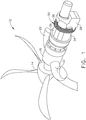
- FIG. 1 shows an engine 12 that includes a plurality of screens 50 arranged in a screen assembly 38 such that each of the screens 50 covers an air intake inlet 34.
- the engine 12 also includes a propeller assembly 14, a housing 16, a pair of exhausts 22, and a mounting block 28.
- the engine 12 is a turboprop aircraft engine. In other embodiments the engine 12 could be configured for use in marine and industrial applications.
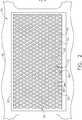
- the screen 50 includes a frame 53 configured to support mesh assembly 70.
- the frame 53 is of tubular construction and is configured to support mesh 55.
- the mesh 55 is configured to allow air from the outside of the engine 12 through the air intake inlet 34 and into the air intake duct 32 while preventing foreign object debris (FOD) from entering the air intake duct 32 (see FIG. 3 ).
- FOD foreign object debris
- the mesh assembly 70 also includes a first tier 73 of first tier tubes 74 that is positioned offset from and in contact with a second tier 83 of second tier tubes 84.
- the first tier 73 and the second tier 83 are positioned relative to each other such that first tier tubes 74 and second tier tubes 84 cross to define a plurality of intersections 92.
- the tubes 74 and the tubes 84 are cross-members configured to block FOD.
- a plurality of screen openings 94 are defined by the intersections 92 and portions of the first tier tubes 74 and the second-tier tubes 84. Openings 94 are sized such that FOD above a predetermined size and shape cannot pass through.
- the relative position of the first tier 73 and the second tier 83 can vary between embodiments. In some embodiments the first tier 73 and the second tier 83 are not offset and are in the same plane. In other embodiments the first tier 73 and the second tier 83 are spaced-apart from each other. And in other embodiments there can be more than two tiers and some of the tiers can be in contact and some can be spaced-apart.
- each screen 50 is also chosen to allow a predetermined airflow through screen 50. It is believed that the aerodynamically efficient tubular construction of portions of the screen 50 provide additional strength with less weight than similarly sized solid components provide.
- FIG. 4 shows the screen assembly 38 in a radially exploded view including partial sections of a plurality of struts 31.
- the screens 50 are radially distributed around the engine 12 and each of the screens 50 are positioned over an associated air intake inlet 34 and air intake duct 32.
- the air intake duct 32 is defined by a strut 31.
- the tubes 74 and 84 are configured such that their respective cross section are not circular but instead are aerodynamically shaped and, as a result, are aerodynamically efficient.
- aerodynamically shaped refers to shapes of objects that are configured to pass through air such that less turbulence and/or drag is produced around the object than if the object generally circular shapes such as round wire.
- aerodynamically efficient refers to the characteristic of a structure that has a ratio of drag to thickness or diameter that is lower than that of an object having a generally circular cross section such as a round wire.
- tubes 74 and 84 within a single embodiment have the same exterior shape as shown in FIG.
- aerodynamically efficient shapes can vary from embodiment to embodiment and can be shapes other than those described herein.
- One aerodynamically efficient shape for subsonic speeds is a tear drop as exhibited by the cross section of tube 174 shown in FIG. 7 .
- the tear drop shape is symmetrical about an axis that extends from a round front to a tapered tip.
- Another aerodynamically efficient shape is the symmetrical forward and aft diamond shape of tube 274 shown in FIG. 8 and having a narrow nose and tail.
- a third aerodynamically efficient shape is an airfoil as exhibited by tube 374 and shown in FIG. 9 .
- the tube 374 has a convex side that curves away from an opposing concave side as shown. Another variation of the airfoil shape is shown in FIG.
- tube 474 is a truncated airfoil that has less curvature in the concave side and a rounded tail in comparison with tube 374.
- the most aerodynamically efficient shape is the teardrop.
Landscapes
- Engineering & Computer Science (AREA)
- Chemical & Material Sciences (AREA)
- Combustion & Propulsion (AREA)
- Mechanical Engineering (AREA)
- General Engineering & Computer Science (AREA)
- Aviation & Aerospace Engineering (AREA)
- Filtering Of Dispersed Particles In Gases (AREA)
- Structures Of Non-Positive Displacement Pumps (AREA)
- Filtering Materials (AREA)
- Cooling, Air Intake And Gas Exhaust, And Fuel Tank Arrangements In Propulsion Units (AREA)
Abstract
Description
- The present invention relates to aircraft engine efficiency and more specifically to an aerodynamic apparatus for inlet foreign object debris (FOD) screens.
- Inlet screens for the prevention of foreign object debris ("FOD") are necessary for protection from potential damage and blockages that can be caused by FOD. Conventional FOD screens are formed from wire having a generally cylindrical cross section. Conventional screens cause drag as air passes through the screen resulting in diminished efficiency of the engine. Therefore there is a need for an inlet screen that is more aerodynamically efficient than conventional screens formed from generally cylindrical wire.
- This need is addressed by a screen having aerodynamically-efficient cross-members.
- According to one aspect of the present invention, there is provided an apparatus for providing foreign object debris protection for an air intake of an aircraft engine. The apparatus includes a frame and a plurality of cross-members. The cross-members are positioned in the frame to define a plurality of screen openings. At least one of the cross-members has an aerodynamically efficient cross section.
- The invention may be best understood by reference to the following description taken in conjunction with the accompanying drawing figures in which:
-
FIG. 1 shows a perspective view of an aircraft engine that includes a plurality of FOD screens according to the present invention; -
FIG. 2 shows a plan view of a screen according to the present invention; -
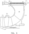
FIG. 3 shows a side cutaway view of the screen taken along line 3-3 shown inFIG. 2 ; -
FIG. 4 shows a radially expanded view of a set of screens with sections of an associated engine; -
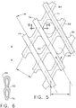
FIG. 5 shows a section of a screen; -
FIG. 6 shows a section of an intersection of two tubes in a screen; and -
FIGS. 7 - 10 show cross-sections of various wires according to alternative embodiments of the present invention. - Referring to the drawings wherein identical reference numerals denote the same elements throughout the various views,
FIG. 1 shows anengine 12 that includes a plurality ofscreens 50 arranged in ascreen assembly 38 such that each of thescreens 50 covers anair intake inlet 34. Theengine 12 also includes apropeller assembly 14, ahousing 16, a pair ofexhausts 22, and amounting block 28. In the illustrated embodiment theengine 12 is a turboprop aircraft engine. In other embodiments theengine 12 could be configured for use in marine and industrial applications. - Referring now to
FIG. 2 , a section of thescreen assembly 38 is shown such that anexemplar screen 50 is presented in plan view. Thescreen 50 includes aframe 53 configured to supportmesh assembly 70. In the illustrated embodiment, theframe 53 is of tubular construction and is configured to supportmesh 55. Themesh 55 is configured to allow air from the outside of theengine 12 through theair intake inlet 34 and into theair intake duct 32 while preventing foreign object debris (FOD) from entering the air intake duct 32 (seeFIG. 3 ). - The
mesh assembly 70 also includes afirst tier 73 offirst tier tubes 74 that is positioned offset from and in contact with asecond tier 83 ofsecond tier tubes 84. Thefirst tier 73 and thesecond tier 83 are positioned relative to each other such thatfirst tier tubes 74 andsecond tier tubes 84 cross to define a plurality ofintersections 92. Thetubes 74 and thetubes 84 are cross-members configured to block FOD. Continuing to refer toFIGS. 2 and5 , a plurality ofscreen openings 94 are defined by theintersections 92 and portions of thefirst tier tubes 74 and the second-tier tubes 84.Openings 94 are sized such that FOD above a predetermined size and shape cannot pass through. - The relative position of the
first tier 73 and thesecond tier 83 can vary between embodiments. In some embodiments thefirst tier 73 and thesecond tier 83 are not offset and are in the same plane. In other embodiments thefirst tier 73 and thesecond tier 83 are spaced-apart from each other. And in other embodiments there can be more than two tiers and some of the tiers can be in contact and some can be spaced-apart. - In addition, the number of
openings 94 in eachscreen 50 is also chosen to allow a predetermined airflow throughscreen 50. It is believed that the aerodynamically efficient tubular construction of portions of thescreen 50 provide additional strength with less weight than similarly sized solid components provide. - Referring now to
FIG. 4 , which shows thescreen assembly 38 in a radially exploded view including partial sections of a plurality ofstruts 31. Thescreens 50 are radially distributed around theengine 12 and each of thescreens 50 are positioned over an associatedair intake inlet 34 andair intake duct 32. Theair intake duct 32 is defined by astrut 31. - The
tubes tubes FIG. 3 but it should be appreciated that the shapes of thetubes screen 50. As can be seen inFIGS. 3 and6 - 10 , aerodynamically efficient shapes can vary from embodiment to embodiment and can be shapes other than those described herein. - One aerodynamically efficient shape for subsonic speeds is a tear drop as exhibited by the cross section of
tube 174 shown inFIG. 7 . The tear drop shape is symmetrical about an axis that extends from a round front to a tapered tip. Another aerodynamically efficient shape is the symmetrical forward and aft diamond shape oftube 274 shown inFIG. 8 and having a narrow nose and tail. A third aerodynamically efficient shape is an airfoil as exhibited bytube 374 and shown inFIG. 9 . Thetube 374 has a convex side that curves away from an opposing concave side as shown. Another variation of the airfoil shape is shown inFIG. 10 in whichtube 474 is a truncated airfoil that has less curvature in the concave side and a rounded tail in comparison withtube 374. For speeds lower than the speed of sound, the most aerodynamically efficient shape is the teardrop. - The foregoing has described an apparatus for providing aerodynamically efficient FOD screen. Because of the aerodynamic efficiency of the above described FOD screens, they provide protection with less wasted energy. Such screens can be used for any machine or application that requires FOD-free fluid (such as air and other gases or liquids). Such other applications include IC engines, fans, cooling water, oil, etc. All of the features disclosed in this specification (including any accompanying claims, abstract and drawings), and/or all of the steps of any method or process so disclosed, may be combined in any combination, except combinations where at least some of such features and/or steps are mutually exclusive.
- Each feature disclosed in this specification (including any accompanying claims, abstract and drawings) may be replaced by alternative features serving the same, equivalent or similar purpose, unless expressly stated otherwise. Thus, unless expressly stated otherwise, each feature disclosed is one example only of a generic series of equivalent or similar features.
- The invention is not restricted to the details of the foregoing embodiment(s). The invention extends to any novel one, or any novel combination, of the features disclosed in this specification (including any accompanying potential points of novelty, abstract and drawings), or to any novel one, or any novel combination, of the steps of any method or process so disclosed.
- Various aspects and embodiments of the present invention are defined by the following numbered clauses:
- 1. An apparatus for providing foreign object debris protection for an air intake of an aircraft engine, the apparatus comprising;
a frame;
a plurality of cross-members positioned in the frame to define a plurality of screen openings; and
wherein at least one of the cross-members has an aerodynamically efficient cross section. - 2. The apparatus according to clause 1, wherein the cross-members are tubular.
- 3. The apparatus according to any preceding clause, wherein the frame is configured to support a mesh assembly formed of the tubular cross-members.
- 4. The apparatus according to any preceding clause, wherein the frame is also configured to support a mesh that is not configured to be heated.
- 5. The apparatus according to any preceding clause, wherein the tubular cross-members are arranged in a tier and are positioned generally parallel to each other.
- 6. The apparatus according to any preceding clause, wherein the tubes are arranged in two tiers such that the tubular cross-members in each tier are parallel to the tubular cross-members also in that tier and the tubular cross-members in each tier cross the tubular cross-members of the other tier to form a mesh.
- 7. The apparatus according to any preceding clause, wherein the mesh is configured to prevent foreign object debris from entering the air intake of the engine.
- 8. The apparatus according to any preceding clause, wherein the tubular cross-members are in a first-tier and solid wire links are positioned in a second-tier such that the first tier and the second tier together define a mesh.
- 9. The apparatus according to any preceding clause, wherein the aerodynamically efficient cross-section is teardrop shaped.
- 10. The apparatus according to any preceding clause, wherein a tail of the cross-section is narrow.
- 11. The apparatus according to any preceding clause, wherein a tail of the cross-section pointed.
- 12. The apparatus according to any preceding clause, wherein a tail of the cross-section is rounded.
- 13. The apparatus according to any preceding clause, wherein the aerodynamically efficient cross-section is generally diamond shaped.
- 14. The apparatus according to any preceding clause, wherein one end of the cross-section is general rounded.
- 15. The apparatus according to any preceding clause, wherein both ends of the cross section are rounded.
Claims (15)
- An apparatus (50) for providing foreign object debris protection for an air intake (34) of an aircraft engine (12), the apparatus (50) comprising;
a frame (53);
a plurality of cross-members (74, 84, 74, 174, 184, 274, 284, 374, 384) (74, 84, 74, 174, 184, 274, 284, 374, 384) positioned in the frame (53) to define a plurality of screen openings (94); and
wherein at least one of the cross-members (74, 84, 74, 174, 184, 274, 284, 374, 384) has an aerodynamically efficient cross section. - The apparatus (50) according to claim 1, wherein the cross-members (74, 84, 74, 174, 184, 274, 284, 374, 384) are tubular.
- The apparatus (50) according to claim 2, wherein the frame (53) is configured to support a mesh (55) assembly (70) formed of the tubular cross-members (74, 84, 74, 174, 184, 274, 284, 374, 384).
- The apparatus (50) according to any preceding claim, wherein the frame (53) is also configured to support a mesh (55) that is not configured to be heated.
- The apparatus (50) according to claim 2 or any claim dependent thereon, wherein the tubular cross-members (74, 84, 74, 174, 184, 274, 284, 374, 384) are arranged in a tier (73) and are positioned generally parallel to each other.
- The apparatus (50) according to claim 5, wherein the tubular cross-members (74, 84, 74, 174, 184, 274, 284, 374, 384) are arranged in two tiers (73, 83) such that the tubular cross-members (74, 84, 74, 174, 184, 274, 284, 374, 384) in each tier (73,83) are parallel to the tubular cross-members (74, 84, 74, 174, 184, 274, 284, 374, 384) also in that tier (73,83) and the tubular cross-members (74, 84, 74, 174, 184, 274, 284, 374, 384) in each tier (73,83) cross the tubular cross-members (74, 84, 74, 174, 184, 274, 284, 374, 384) of the other tier (73,83) to form a mesh (55).
- The apparatus (50) according to claim 6, wherein the mesh (55) is configured to prevent foreign object debris from entering the air intake (34) of the engine (12).
- The apparatus (50) according to claim 2 or any claim dependent thereon, wherein the tubular cross-members (74, 84, 74, 174, 184, 274, 284, 374, 384) are in a first-tier (73) and solid wire links are positioned in a second-tier (83)such that the first tier (73) and the second tier (83) together define a mesh (55).
- The apparatus (50) according to any preceding claim, wherein the aerodynamically efficient cross-section is teardrop shaped.
- The apparatus (50) according to claim 9, wherein a tail of the cross-section is narrow.
- The apparatus (50) according to claim 9, wherein a tail of the cross-section is pointed.
- The apparatus (50) according to claim 9, wherein a tail of the cross-section is rounded.
- The apparatus (50) according to any preceding claim, wherein the aerodynamically efficient cross-section is generally diamond shaped.
- The apparatus (50) according to claim 13, wherein one end of the cross-section is general rounded.
- The apparatus (50) according to claim 14, wherein both ends of the cross section are rounded.
Applications Claiming Priority (1)
| Application Number | Priority Date | Filing Date | Title |
|---|---|---|---|
| PL420326A PL420326A1 (en) | 2017-01-27 | 2017-01-27 | Intake shield for aircraft engines |
Publications (2)
| Publication Number | Publication Date |
|---|---|
| EP3354879A1 true EP3354879A1 (en) | 2018-08-01 |
| EP3354879B1 EP3354879B1 (en) | 2022-10-19 |
Family
ID=61027503
Family Applications (1)
| Application Number | Title | Priority Date | Filing Date |
|---|---|---|---|
| EP18153269.8A Active EP3354879B1 (en) | 2017-01-27 | 2018-01-24 | Inlet screen for aircraft engines |
Country Status (4)
| Country | Link |
|---|---|
| US (1) | US11084599B2 (en) |
| EP (1) | EP3354879B1 (en) |
| CN (1) | CN108361110B (en) |
| PL (1) | PL420326A1 (en) |
Families Citing this family (8)
| Publication number | Priority date | Publication date | Assignee | Title |
|---|---|---|---|---|
| US11359543B2 (en) | 2019-06-07 | 2022-06-14 | Raytheon Technologies Corporation | Attritable engine additively manufactured inlet cap |
| CN112324573B (en) * | 2020-10-29 | 2022-03-25 | 中国航发湖南动力机械研究所 | Aeroengine air inlet cover |
| US12479587B2 (en) * | 2020-12-21 | 2025-11-25 | General Electric Company Polska Sp. Z O.O. | Skeleton screen for an air intake portion of a machine |
| US11702989B2 (en) | 2021-09-24 | 2023-07-18 | Hamilton Sundstrand Corporation | Last chance screen for aircraft fuel system |
| US11808161B2 (en) | 2022-04-11 | 2023-11-07 | General Electric Company | Flow control mechanism for nacelle of turbofan engine |
| US12286941B2 (en) | 2022-04-26 | 2025-04-29 | General Electric Company | Reverse thrust turbofan engine |
| US12276227B1 (en) | 2023-10-23 | 2025-04-15 | General Electric Company | Turbine engine screen |
| US12392284B1 (en) | 2024-02-13 | 2025-08-19 | General Electric Company | Cyclonic separator for gas turbine engine |
Citations (3)
| Publication number | Priority date | Publication date | Assignee | Title |
|---|---|---|---|---|
| US2747685A (en) * | 1954-01-12 | 1956-05-29 | United Aircraft Corp | Inlet screen segment |
| GB1474390A (en) * | 1974-09-27 | 1977-05-25 | Secr Defence | Debris guard |
| WO2015066361A1 (en) * | 2013-11-04 | 2015-05-07 | United Technologies Corporation | Turbomachinery inlet screen |
Family Cites Families (28)
| Publication number | Priority date | Publication date | Assignee | Title |
|---|---|---|---|---|
| US1177320A (en) | 1915-06-29 | 1916-03-28 | Robert Grabowsky | Production of hollow grate-bars. |
| US2046458A (en) | 1934-11-10 | 1936-07-07 | Edward E Johnson Inc | Screen |
| US2663993A (en) * | 1945-10-10 | 1953-12-29 | Westinghouse Electric Corp | Deicing apparatus |
| US3428278A (en) | 1966-06-01 | 1969-02-18 | Fort Wayne Metals Inc | Permeable airfoil skin |
| GB1201096A (en) * | 1966-11-15 | 1970-08-05 | United Aircraft Corp | Air particle separator |
| US3526953A (en) | 1967-01-03 | 1970-09-08 | Gen Electric | Method for making lightweight metallic structure |
| US3589694A (en) | 1969-08-19 | 1971-06-29 | Philips Corp | Supporting plate for objects to be subjected to a thermal treatment |
| US3667108A (en) | 1970-04-17 | 1972-06-06 | Us Navy | Method of making a beryllium titanium composite |
| FR2129931B1 (en) | 1971-03-22 | 1973-12-28 | Vidal Benjamin | |
| US3908683A (en) | 1974-06-03 | 1975-09-30 | Boeing Co | Translating multi-ring inlet for gas turbine engines |
| US20020166654A1 (en) | 2001-05-02 | 2002-11-14 | Smalc Martin D. | Finned Heat Sink Assemblies |
| US20080098891A1 (en) | 2006-10-25 | 2008-05-01 | General Electric Company | Turbine inlet air treatment apparatus |
| US20090321056A1 (en) | 2008-03-11 | 2009-12-31 | Tessera, Inc. | Multi-stage electrohydrodynamic fluid accelerator apparatus |
| KR100990309B1 (en) | 2008-06-03 | 2010-10-26 | 한국수력원자력 주식회사 | heat transmitter |
| US9255745B2 (en) | 2009-01-05 | 2016-02-09 | Hamilton Sundstrand Corporation | Heat exchanger |
| US20100263847A1 (en) | 2009-04-21 | 2010-10-21 | Hamilton Sundstrand Corporation | Microchannel heat exchanger |
| US8756909B2 (en) * | 2009-07-22 | 2014-06-24 | The CtFoT Group LLC | Aircraft engine protection device |
| US10518490B2 (en) | 2013-03-14 | 2019-12-31 | Board Of Regents, The University Of Texas System | Methods and systems for embedding filaments in 3D structures, structural components, and structural electronic, electromagnetic and electromechanical components/devices |
| CN202673454U (en) * | 2012-05-23 | 2013-01-16 | 哈尔滨工程大学 | Inlet protective screen cover |
| WO2014135942A1 (en) * | 2013-03-06 | 2014-09-12 | Bombardier Inc. | Apparatus for protecting aircraft components against foreign object damage |
| DE102014214107A1 (en) | 2013-08-26 | 2015-02-26 | Robert Bosch Gmbh | transport device |
| US9212606B2 (en) | 2013-12-24 | 2015-12-15 | Khalid Hamad Mutleb ALNAFISAH | Bird strike prevention device for jet engine, and airplane incorporating the same |
| US9784111B2 (en) | 2014-09-29 | 2017-10-10 | General Electric Company | Additive manufacturing method for fabricating a component |
| US9713861B2 (en) | 2014-09-29 | 2017-07-25 | General Electric Company | Manufacturing system and method for fabricating a component |
| CN105253311B (en) * | 2015-09-28 | 2017-08-08 | 易瓦特科技股份公司 | Depopulated helicopter |
| US9714630B2 (en) * | 2015-10-07 | 2017-07-25 | General Electric Company | Noise baffle for a rotary machine and method of making same |
| US10450954B2 (en) * | 2016-03-17 | 2019-10-22 | General Electric Company | Internally heated engine inlet screen for aircraft engines |
| EP3444447A1 (en) * | 2017-08-14 | 2019-02-20 | General Electric Company | Inlet frame for a gas turbine engine |
-
2017
- 2017-01-27 PL PL420326A patent/PL420326A1/en unknown
-
2018
- 2018-01-12 US US15/869,823 patent/US11084599B2/en active Active
- 2018-01-24 EP EP18153269.8A patent/EP3354879B1/en active Active
- 2018-01-26 CN CN201810078290.XA patent/CN108361110B/en active Active
Patent Citations (3)
| Publication number | Priority date | Publication date | Assignee | Title |
|---|---|---|---|---|
| US2747685A (en) * | 1954-01-12 | 1956-05-29 | United Aircraft Corp | Inlet screen segment |
| GB1474390A (en) * | 1974-09-27 | 1977-05-25 | Secr Defence | Debris guard |
| WO2015066361A1 (en) * | 2013-11-04 | 2015-05-07 | United Technologies Corporation | Turbomachinery inlet screen |
Also Published As
| Publication number | Publication date |
|---|---|
| US20180215478A1 (en) | 2018-08-02 |
| US11084599B2 (en) | 2021-08-10 |
| CN108361110A (en) | 2018-08-03 |
| PL420326A1 (en) | 2018-07-30 |
| EP3354879B1 (en) | 2022-10-19 |
| CN108361110B (en) | 2022-07-08 |
Similar Documents
| Publication | Publication Date | Title |
|---|---|---|
| US11084599B2 (en) | Inlet screen for aircraft engines | |
| EP2998542B1 (en) | Pre-cooler inlet duct with active flow-control and method including the same | |
| JP4794317B2 (en) | Turbine airfoil | |
| JP6019578B2 (en) | Turbine blade | |
| EP2738392B1 (en) | Fan blade for a turbofan gas turbine engine | |
| US9506422B2 (en) | Efficient, low pressure ratio propulsor for gas turbine engines | |
| US8540480B2 (en) | Aerofoil having a plurality cooling air flows | |
| EP2078823B1 (en) | Cooling arrangement for turbine components | |
| US9121412B2 (en) | Efficient, low pressure ratio propulsor for gas turbine engines | |
| JP6766197B2 (en) | Equipment for deicing the separator nose of aircraft turbine engines | |
| DE3781763T2 (en) | LOW-LOSS PROPELLER BLADE FOR SUPERVISORY RANGE. | |
| GB2164098A (en) | Improvements in or relating to aerofoil section members for turbine engines | |
| JP5070345B2 (en) | Performance improvement method of bypass turbojet engine | |
| JP2013130188A (en) | Gas turbine engine particle separator | |
| CN107201950B (en) | Internally heated engine inlet mesh screen for aero engines | |
| CN109139255B (en) | Exhaust assembly with vortex generator and exhaust method thereof | |
| EP3034804A1 (en) | Pre-diffuser strut for gas turbine engine | |
| EP2801701A1 (en) | Turbine blade | |
| US8061983B1 (en) | Exhaust diffuser strut with stepped trailing edge | |
| EP3173586A1 (en) | Engine component with film cooling | |
| US20170159449A1 (en) | Gas turbine engine with fillet film holes | |
| US20110052413A1 (en) | Cooled gas turbine engine airflow member | |
| CN112313394B (en) | Turbine blades including passive systems for reducing vortices in the airflow passing over said blades | |
| EP3002210B1 (en) | Engine nacelle | |
| WO2014143292A1 (en) | Fan airfoil shrouds with area ruling in the shrouds |
Legal Events
| Date | Code | Title | Description |
|---|---|---|---|
| PUAI | Public reference made under article 153(3) epc to a published international application that has entered the european phase |
Free format text: ORIGINAL CODE: 0009012 |
|
| STAA | Information on the status of an ep patent application or granted ep patent |
Free format text: STATUS: THE APPLICATION HAS BEEN PUBLISHED |
|
| AK | Designated contracting states |
Kind code of ref document: A1 Designated state(s): AL AT BE BG CH CY CZ DE DK EE ES FI FR GB GR HR HU IE IS IT LI LT LU LV MC MK MT NL NO PL PT RO RS SE SI SK SM TR |
|
| AX | Request for extension of the european patent |
Extension state: BA ME |
|
| STAA | Information on the status of an ep patent application or granted ep patent |
Free format text: STATUS: REQUEST FOR EXAMINATION WAS MADE |
|
| 17P | Request for examination filed |
Effective date: 20190201 |
|
| RBV | Designated contracting states (corrected) |
Designated state(s): AL AT BE BG CH CY CZ DE DK EE ES FI FR GB GR HR HU IE IS IT LI LT LU LV MC MK MT NL NO PL PT RO RS SE SI SK SM TR |
|
| STAA | Information on the status of an ep patent application or granted ep patent |
Free format text: STATUS: EXAMINATION IS IN PROGRESS |
|
| 17Q | First examination report despatched |
Effective date: 20200807 |
|
| GRAP | Despatch of communication of intention to grant a patent |
Free format text: ORIGINAL CODE: EPIDOSNIGR1 |
|
| STAA | Information on the status of an ep patent application or granted ep patent |
Free format text: STATUS: GRANT OF PATENT IS INTENDED |
|
| INTG | Intention to grant announced |
Effective date: 20220509 |
|
| GRAS | Grant fee paid |
Free format text: ORIGINAL CODE: EPIDOSNIGR3 |
|
| GRAA | (expected) grant |
Free format text: ORIGINAL CODE: 0009210 |
|
| STAA | Information on the status of an ep patent application or granted ep patent |
Free format text: STATUS: THE PATENT HAS BEEN GRANTED |
|
| AK | Designated contracting states |
Kind code of ref document: B1 Designated state(s): AL AT BE BG CH CY CZ DE DK EE ES FI FR GB GR HR HU IE IS IT LI LT LU LV MC MK MT NL NO PL PT RO RS SE SI SK SM TR |
|
| REG | Reference to a national code |
Ref country code: GB Ref legal event code: FG4D |
|
| REG | Reference to a national code |
Ref country code: CH Ref legal event code: EP |
|
| REG | Reference to a national code |
Ref country code: IE Ref legal event code: FG4D |
|
| REG | Reference to a national code |
Ref country code: DE Ref legal event code: R096 Ref document number: 602018041866 Country of ref document: DE |
|
| REG | Reference to a national code |
Ref country code: AT Ref legal event code: REF Ref document number: 1525675 Country of ref document: AT Kind code of ref document: T Effective date: 20221115 |
|
| REG | Reference to a national code |
Ref country code: LT Ref legal event code: MG9D |
|
| REG | Reference to a national code |
Ref country code: NL Ref legal event code: MP Effective date: 20221019 |
|
| REG | Reference to a national code |
Ref country code: AT Ref legal event code: MK05 Ref document number: 1525675 Country of ref document: AT Kind code of ref document: T Effective date: 20221019 |
|
| PG25 | Lapsed in a contracting state [announced via postgrant information from national office to epo] |
Ref country code: NL Free format text: LAPSE BECAUSE OF FAILURE TO SUBMIT A TRANSLATION OF THE DESCRIPTION OR TO PAY THE FEE WITHIN THE PRESCRIBED TIME-LIMIT Effective date: 20221019 |
|
| PG25 | Lapsed in a contracting state [announced via postgrant information from national office to epo] |
Ref country code: SE Free format text: LAPSE BECAUSE OF FAILURE TO SUBMIT A TRANSLATION OF THE DESCRIPTION OR TO PAY THE FEE WITHIN THE PRESCRIBED TIME-LIMIT Effective date: 20221019 Ref country code: PT Free format text: LAPSE BECAUSE OF FAILURE TO SUBMIT A TRANSLATION OF THE DESCRIPTION OR TO PAY THE FEE WITHIN THE PRESCRIBED TIME-LIMIT Effective date: 20230220 Ref country code: NO Free format text: LAPSE BECAUSE OF FAILURE TO SUBMIT A TRANSLATION OF THE DESCRIPTION OR TO PAY THE FEE WITHIN THE PRESCRIBED TIME-LIMIT Effective date: 20230119 Ref country code: LT Free format text: LAPSE BECAUSE OF FAILURE TO SUBMIT A TRANSLATION OF THE DESCRIPTION OR TO PAY THE FEE WITHIN THE PRESCRIBED TIME-LIMIT Effective date: 20221019 Ref country code: FI Free format text: LAPSE BECAUSE OF FAILURE TO SUBMIT A TRANSLATION OF THE DESCRIPTION OR TO PAY THE FEE WITHIN THE PRESCRIBED TIME-LIMIT Effective date: 20221019 Ref country code: ES Free format text: LAPSE BECAUSE OF FAILURE TO SUBMIT A TRANSLATION OF THE DESCRIPTION OR TO PAY THE FEE WITHIN THE PRESCRIBED TIME-LIMIT Effective date: 20221019 Ref country code: AT Free format text: LAPSE BECAUSE OF FAILURE TO SUBMIT A TRANSLATION OF THE DESCRIPTION OR TO PAY THE FEE WITHIN THE PRESCRIBED TIME-LIMIT Effective date: 20221019 |
|
| PG25 | Lapsed in a contracting state [announced via postgrant information from national office to epo] |
Ref country code: RS Free format text: LAPSE BECAUSE OF FAILURE TO SUBMIT A TRANSLATION OF THE DESCRIPTION OR TO PAY THE FEE WITHIN THE PRESCRIBED TIME-LIMIT Effective date: 20221019 Ref country code: PL Free format text: LAPSE BECAUSE OF FAILURE TO SUBMIT A TRANSLATION OF THE DESCRIPTION OR TO PAY THE FEE WITHIN THE PRESCRIBED TIME-LIMIT Effective date: 20221019 Ref country code: LV Free format text: LAPSE BECAUSE OF FAILURE TO SUBMIT A TRANSLATION OF THE DESCRIPTION OR TO PAY THE FEE WITHIN THE PRESCRIBED TIME-LIMIT Effective date: 20221019 Ref country code: IS Free format text: LAPSE BECAUSE OF FAILURE TO SUBMIT A TRANSLATION OF THE DESCRIPTION OR TO PAY THE FEE WITHIN THE PRESCRIBED TIME-LIMIT Effective date: 20230219 Ref country code: HR Free format text: LAPSE BECAUSE OF FAILURE TO SUBMIT A TRANSLATION OF THE DESCRIPTION OR TO PAY THE FEE WITHIN THE PRESCRIBED TIME-LIMIT Effective date: 20221019 Ref country code: GR Free format text: LAPSE BECAUSE OF FAILURE TO SUBMIT A TRANSLATION OF THE DESCRIPTION OR TO PAY THE FEE WITHIN THE PRESCRIBED TIME-LIMIT Effective date: 20230120 |
|
| P01 | Opt-out of the competence of the unified patent court (upc) registered |
Effective date: 20230507 |
|
| REG | Reference to a national code |
Ref country code: DE Ref legal event code: R097 Ref document number: 602018041866 Country of ref document: DE |
|
| PG25 | Lapsed in a contracting state [announced via postgrant information from national office to epo] |
Ref country code: SM Free format text: LAPSE BECAUSE OF FAILURE TO SUBMIT A TRANSLATION OF THE DESCRIPTION OR TO PAY THE FEE WITHIN THE PRESCRIBED TIME-LIMIT Effective date: 20221019 Ref country code: RO Free format text: LAPSE BECAUSE OF FAILURE TO SUBMIT A TRANSLATION OF THE DESCRIPTION OR TO PAY THE FEE WITHIN THE PRESCRIBED TIME-LIMIT Effective date: 20221019 Ref country code: EE Free format text: LAPSE BECAUSE OF FAILURE TO SUBMIT A TRANSLATION OF THE DESCRIPTION OR TO PAY THE FEE WITHIN THE PRESCRIBED TIME-LIMIT Effective date: 20221019 Ref country code: DK Free format text: LAPSE BECAUSE OF FAILURE TO SUBMIT A TRANSLATION OF THE DESCRIPTION OR TO PAY THE FEE WITHIN THE PRESCRIBED TIME-LIMIT Effective date: 20221019 Ref country code: CZ Free format text: LAPSE BECAUSE OF FAILURE TO SUBMIT A TRANSLATION OF THE DESCRIPTION OR TO PAY THE FEE WITHIN THE PRESCRIBED TIME-LIMIT Effective date: 20221019 |
|
| PLBE | No opposition filed within time limit |
Free format text: ORIGINAL CODE: 0009261 |
|
| STAA | Information on the status of an ep patent application or granted ep patent |
Free format text: STATUS: NO OPPOSITION FILED WITHIN TIME LIMIT |
|
| PG25 | Lapsed in a contracting state [announced via postgrant information from national office to epo] |
Ref country code: SK Free format text: LAPSE BECAUSE OF FAILURE TO SUBMIT A TRANSLATION OF THE DESCRIPTION OR TO PAY THE FEE WITHIN THE PRESCRIBED TIME-LIMIT Effective date: 20221019 Ref country code: AL Free format text: LAPSE BECAUSE OF FAILURE TO SUBMIT A TRANSLATION OF THE DESCRIPTION OR TO PAY THE FEE WITHIN THE PRESCRIBED TIME-LIMIT Effective date: 20221019 |
|
| REG | Reference to a national code |
Ref country code: CH Ref legal event code: PL |
|
| 26N | No opposition filed |
Effective date: 20230720 |
|
| PG25 | Lapsed in a contracting state [announced via postgrant information from national office to epo] |
Ref country code: LU Free format text: LAPSE BECAUSE OF NON-PAYMENT OF DUE FEES Effective date: 20230124 |
|
| REG | Reference to a national code |
Ref country code: BE Ref legal event code: MM Effective date: 20230131 |
|
| PG25 | Lapsed in a contracting state [announced via postgrant information from national office to epo] |
Ref country code: LI Free format text: LAPSE BECAUSE OF NON-PAYMENT OF DUE FEES Effective date: 20230131 Ref country code: CH Free format text: LAPSE BECAUSE OF NON-PAYMENT OF DUE FEES Effective date: 20230131 |
|
| PG25 | Lapsed in a contracting state [announced via postgrant information from national office to epo] |
Ref country code: SI Free format text: LAPSE BECAUSE OF FAILURE TO SUBMIT A TRANSLATION OF THE DESCRIPTION OR TO PAY THE FEE WITHIN THE PRESCRIBED TIME-LIMIT Effective date: 20221019 Ref country code: BE Free format text: LAPSE BECAUSE OF NON-PAYMENT OF DUE FEES Effective date: 20230131 |
|
| PG25 | Lapsed in a contracting state [announced via postgrant information from national office to epo] |
Ref country code: IE Free format text: LAPSE BECAUSE OF NON-PAYMENT OF DUE FEES Effective date: 20230124 |
|
| PG25 | Lapsed in a contracting state [announced via postgrant information from national office to epo] |
Ref country code: IT Free format text: LAPSE BECAUSE OF FAILURE TO SUBMIT A TRANSLATION OF THE DESCRIPTION OR TO PAY THE FEE WITHIN THE PRESCRIBED TIME-LIMIT Effective date: 20221019 |
|
| PG25 | Lapsed in a contracting state [announced via postgrant information from national office to epo] |
Ref country code: MC Free format text: LAPSE BECAUSE OF FAILURE TO SUBMIT A TRANSLATION OF THE DESCRIPTION OR TO PAY THE FEE WITHIN THE PRESCRIBED TIME-LIMIT Effective date: 20221019 |
|
| PG25 | Lapsed in a contracting state [announced via postgrant information from national office to epo] |
Ref country code: MC Free format text: LAPSE BECAUSE OF FAILURE TO SUBMIT A TRANSLATION OF THE DESCRIPTION OR TO PAY THE FEE WITHIN THE PRESCRIBED TIME-LIMIT Effective date: 20221019 |
|
| PG25 | Lapsed in a contracting state [announced via postgrant information from national office to epo] |
Ref country code: BG Free format text: LAPSE BECAUSE OF FAILURE TO SUBMIT A TRANSLATION OF THE DESCRIPTION OR TO PAY THE FEE WITHIN THE PRESCRIBED TIME-LIMIT Effective date: 20221019 |
|
| PG25 | Lapsed in a contracting state [announced via postgrant information from national office to epo] |
Ref country code: BG Free format text: LAPSE BECAUSE OF FAILURE TO SUBMIT A TRANSLATION OF THE DESCRIPTION OR TO PAY THE FEE WITHIN THE PRESCRIBED TIME-LIMIT Effective date: 20221019 |
|
| PG25 | Lapsed in a contracting state [announced via postgrant information from national office to epo] |
Ref country code: CY Free format text: LAPSE BECAUSE OF FAILURE TO SUBMIT A TRANSLATION OF THE DESCRIPTION OR TO PAY THE FEE WITHIN THE PRESCRIBED TIME-LIMIT; INVALID AB INITIO Effective date: 20180124 |
|
| PG25 | Lapsed in a contracting state [announced via postgrant information from national office to epo] |
Ref country code: HU Free format text: LAPSE BECAUSE OF FAILURE TO SUBMIT A TRANSLATION OF THE DESCRIPTION OR TO PAY THE FEE WITHIN THE PRESCRIBED TIME-LIMIT; INVALID AB INITIO Effective date: 20180124 |
|
| PG25 | Lapsed in a contracting state [announced via postgrant information from national office to epo] |
Ref country code: TR Free format text: LAPSE BECAUSE OF FAILURE TO SUBMIT A TRANSLATION OF THE DESCRIPTION OR TO PAY THE FEE WITHIN THE PRESCRIBED TIME-LIMIT Effective date: 20221019 |
|
| PGFP | Annual fee paid to national office [announced via postgrant information from national office to epo] |
Ref country code: GB Payment date: 20251219 Year of fee payment: 9 |
|
| PGFP | Annual fee paid to national office [announced via postgrant information from national office to epo] |
Ref country code: FR Payment date: 20251217 Year of fee payment: 9 |
|
| PGFP | Annual fee paid to national office [announced via postgrant information from national office to epo] |
Ref country code: DE Payment date: 20251217 Year of fee payment: 9 |