EP3354876B1 - Architecture de moteur de turbine à gaz comportant un système à double compresseur - Google Patents
Architecture de moteur de turbine à gaz comportant un système à double compresseur Download PDFInfo
- Publication number
- EP3354876B1 EP3354876B1 EP18154161.6A EP18154161A EP3354876B1 EP 3354876 B1 EP3354876 B1 EP 3354876B1 EP 18154161 A EP18154161 A EP 18154161A EP 3354876 B1 EP3354876 B1 EP 3354876B1
- Authority
- EP
- European Patent Office
- Prior art keywords
- engine
- low pressure
- turbine
- compressor
- high pressure
- Prior art date
- Legal status (The legal status is an assumption and is not a legal conclusion. Google has not performed a legal analysis and makes no representation as to the accuracy of the status listed.)
- Active
Links
- 238000011144 upstream manufacturing Methods 0.000 claims description 8
- 230000009467 reduction Effects 0.000 claims description 4
- 239000007789 gas Substances 0.000 description 23
- 239000000567 combustion gas Substances 0.000 description 7
- 230000006835 compression Effects 0.000 description 4
- 238000007906 compression Methods 0.000 description 4
- 239000000446 fuel Substances 0.000 description 4
- 238000012546 transfer Methods 0.000 description 4
- 238000000034 method Methods 0.000 description 3
- 238000004891 communication Methods 0.000 description 2
- 238000007689 inspection Methods 0.000 description 2
- 238000009434 installation Methods 0.000 description 2
- 238000012986 modification Methods 0.000 description 2
- 230000004048 modification Effects 0.000 description 2
- 108091001599 RGB-10 Proteins 0.000 description 1
- 238000013459 approach Methods 0.000 description 1
- 230000014509 gene expression Effects 0.000 description 1
- 230000006872 improvement Effects 0.000 description 1
- 238000012423 maintenance Methods 0.000 description 1
- 230000003071 parasitic effect Effects 0.000 description 1
- 230000008569 process Effects 0.000 description 1
- 238000012552 review Methods 0.000 description 1
- 230000007704 transition Effects 0.000 description 1
Images


Classifications
-
- F—MECHANICAL ENGINEERING; LIGHTING; HEATING; WEAPONS; BLASTING
- F02—COMBUSTION ENGINES; HOT-GAS OR COMBUSTION-PRODUCT ENGINE PLANTS
- F02C—GAS-TURBINE PLANTS; AIR INTAKES FOR JET-PROPULSION PLANTS; CONTROLLING FUEL SUPPLY IN AIR-BREATHING JET-PROPULSION PLANTS
- F02C3/00—Gas-turbine plants characterised by the use of combustion products as the working fluid
- F02C3/04—Gas-turbine plants characterised by the use of combustion products as the working fluid having a turbine driving a compressor
- F02C3/107—Gas-turbine plants characterised by the use of combustion products as the working fluid having a turbine driving a compressor with two or more rotors connected by power transmission
-
- B—PERFORMING OPERATIONS; TRANSPORTING
- B64—AIRCRAFT; AVIATION; COSMONAUTICS
- B64D—EQUIPMENT FOR FITTING IN OR TO AIRCRAFT; FLIGHT SUITS; PARACHUTES; ARRANGEMENTS OR MOUNTING OF POWER PLANTS OR PROPULSION TRANSMISSIONS IN AIRCRAFT
- B64D27/00—Arrangement or mounting of power plant in aircraft; Aircraft characterised thereby
- B64D27/02—Aircraft characterised by the type or position of power plant
- B64D27/10—Aircraft characterised by the type or position of power plant of gas-turbine type
-
- F—MECHANICAL ENGINEERING; LIGHTING; HEATING; WEAPONS; BLASTING
- F02—COMBUSTION ENGINES; HOT-GAS OR COMBUSTION-PRODUCT ENGINE PLANTS
- F02C—GAS-TURBINE PLANTS; AIR INTAKES FOR JET-PROPULSION PLANTS; CONTROLLING FUEL SUPPLY IN AIR-BREATHING JET-PROPULSION PLANTS
- F02C7/00—Features, components parts, details or accessories, not provided for in, or of interest apart form groups F02C1/00 - F02C6/00; Air intakes for jet-propulsion plants
- F02C7/36—Power transmission arrangements between the different shafts of the gas turbine plant, or between the gas-turbine plant and the power user
-
- F—MECHANICAL ENGINEERING; LIGHTING; HEATING; WEAPONS; BLASTING
- F05—INDEXING SCHEMES RELATING TO ENGINES OR PUMPS IN VARIOUS SUBCLASSES OF CLASSES F01-F04
- F05D—INDEXING SCHEME FOR ASPECTS RELATING TO NON-POSITIVE-DISPLACEMENT MACHINES OR ENGINES, GAS-TURBINES OR JET-PROPULSION PLANTS
- F05D2220/00—Application
- F05D2220/30—Application in turbines
- F05D2220/32—Application in turbines in gas turbines
- F05D2220/325—Application in turbines in gas turbines to drive unshrouded, high solidity propeller
-
- F—MECHANICAL ENGINEERING; LIGHTING; HEATING; WEAPONS; BLASTING
- F05—INDEXING SCHEMES RELATING TO ENGINES OR PUMPS IN VARIOUS SUBCLASSES OF CLASSES F01-F04
- F05D—INDEXING SCHEME FOR ASPECTS RELATING TO NON-POSITIVE-DISPLACEMENT MACHINES OR ENGINES, GAS-TURBINES OR JET-PROPULSION PLANTS
- F05D2250/00—Geometry
- F05D2250/30—Arrangement of components
- F05D2250/31—Arrangement of components according to the direction of their main axis or their axis of rotation
- F05D2250/312—Arrangement of components according to the direction of their main axis or their axis of rotation the axes being parallel to each other
-
- F—MECHANICAL ENGINEERING; LIGHTING; HEATING; WEAPONS; BLASTING
- F05—INDEXING SCHEMES RELATING TO ENGINES OR PUMPS IN VARIOUS SUBCLASSES OF CLASSES F01-F04
- F05D—INDEXING SCHEME FOR ASPECTS RELATING TO NON-POSITIVE-DISPLACEMENT MACHINES OR ENGINES, GAS-TURBINES OR JET-PROPULSION PLANTS
- F05D2260/00—Function
- F05D2260/40—Transmission of power
- F05D2260/403—Transmission of power through the shape of the drive components
- F05D2260/4031—Transmission of power through the shape of the drive components as in toothed gearing
- F05D2260/40311—Transmission of power through the shape of the drive components as in toothed gearing of the epicyclical, planetary or differential type
-
- Y—GENERAL TAGGING OF NEW TECHNOLOGICAL DEVELOPMENTS; GENERAL TAGGING OF CROSS-SECTIONAL TECHNOLOGIES SPANNING OVER SEVERAL SECTIONS OF THE IPC; TECHNICAL SUBJECTS COVERED BY FORMER USPC CROSS-REFERENCE ART COLLECTIONS [XRACs] AND DIGESTS
- Y02—TECHNOLOGIES OR APPLICATIONS FOR MITIGATION OR ADAPTATION AGAINST CLIMATE CHANGE
- Y02T—CLIMATE CHANGE MITIGATION TECHNOLOGIES RELATED TO TRANSPORTATION
- Y02T50/00—Aeronautics or air transport
- Y02T50/60—Efficient propulsion technologies, e.g. for aircraft
Definitions
- the application relates generally to gas turbine engines and, more particularly, to a multi-spool engine architecture having a split compressor system.
- low pressure compressor high pressure compressor, high pressure turbine and low pressure turbine arranged sequentially in this order along the engine axial direction.
- the low pressure compressor at a first end of the engine is drivingly connected to the low pressure turbine at the opposed end of the engine via a low pressure shaft extending concentrically through a hollow high pressure shaft, which, in turn, drivingly connects the high pressure turbine to the high pressure compressor.
- US 2929207 A discloses a prior art gas turbine engine according to the preamble of claim 1.
- the external shaft is parallel to the high pressure shaft.
- a geared connection is provided between the external shaft and at least one of the low pressure compressor and the low pressure turbine to allow the low pressure compressor to be driven at a different speed from that of the low pressure turbine.
- a gear set is operatively connected to the external shaft and configured for inverting a rotational direction of the low pressure compressor relative to the low pressure turbine.
- the external shaft is operatively connected to a mechanical link configured to cause a rotational direction of the low pressure compressor to be opposite to that of the low pressure turbine.
- the external shaft has an input end connected to a downstream side of the low pressure turbine relative to a flow of gas through the core gaspath.
- the external shaft has an output end connected to an upstream side of the low pressure compressor relative to a flow of gas through the core gaspath.
- the low pressure compressor is located at a rear end portion of the engine whereas the low pressure turbine is located at a front end portion of the engine, a gas flowing through the core gaspath from the rear end portion to the front end portion of the engine.
- the external shaft has an input end connected to an upstream side of the low pressure turbine and an output end connected to a downstream side of the low pressure compressor relative to a flow of gas through the core gaspath.
- the engine further comprises an accessory gearbox (AGB), and the low pressure turbine is drivingly connected to the AGB via the external shaft.
- AGB accessory gearbox
- the high pressure turbine is also drivingly connected to the AGB, the AGB having first and second power inputs respectively provided by the low and high pressure turbines.
- the external shaft extends axially from a location upstream of the high pressure compressor to a location downstream of the high pressure turbine.
- the high pressure shaft and the high pressure compressor form a high pressure spool, and the external shaft axially spans the high pressure spool.
- the low pressure turbine comprises a low pressure shaft drivingly connected to a reduction gearbox (RGB) or to a load external to the engine.
- RGB reduction gearbox
- the engine further comprises a propeller drivingly connected to an output end of the RGB.
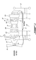
- Fig. 1 illustrates a first example of a multi-spool gas turbine engine 10 of a type preferably provided for use in subsonic flight, and generally comprising an engine core having a turbomachinery with multiple spools which perform compression to pressurize atmospheric air received through an air inlet 13, and which extract energy from combustion gases before they exit the engine via an exhaust outlet 17.
- the engine core further comprises a core gaspath 11 to direct gases from the air inlet 13 to the exhaust outlet 17, as depicted by the flow arrows in Fig. 1 .
- the core gaspath 11 may be annular and concentric relative to the engine centerline CL.
- spool is herein intended to broadly refer to drivingly connected turbine and compressor rotors and is, thus, not limited to a compressor and turbine assembly on a single shaft. As will be seen hereinafter, it also includes a rotary assembly with multiple shafts geared together.
- the engine core includes a low pressure (LP) spool and a high pressure (HP) spool.
- the LP spool generally comprises an LP compressor 12a for pressurizing air received from the air inlet 13 and an LP turbine 12b for extracting energy from combustion gases discharged from a combustor 15 in which compressed air is mixed with fuel and ignited for generating an annular stream of hot combustion gases.
- the LP turbine 12b is connected mechanically to the LP compressor 12a. Flow communication between the two LP compressor 12a and the low pressure turbine 12b is through the high pressure spool and the combustor 15 via the core gaspath 11.
- the LP compressor 12a and the LP turbine 12b are coaxially mounted for rotation about a common axis, which corresponds to the engine centerline CL.
- the HP spool generally comprises an HP compressor 14a connected in flow communication with the LP compressor 12a for receiving pressurized air therefrom via the core gaspath 11.
- the HP spool further comprises an HP turbine 14b immediately downstream of the combustor 15.
- the HP turbine 14b is drivingly connected to the HP compressor 14a via an HP shaft 14c.
- the HP shaft 14c is coaxial to the engine centerline CL.
- the LP compressor 12a, the LP turbine 12b, the HP turbine 14b and the HP compressor 14a are all mounted for rotation about the engine centerline CL.
- the HP spool may be drivingly connected to an accessory gearbox (AGB) 28 coaxially mounted at the rear end of the engine 10 for providing drive outputs to various accessories (e.g.
- AGB accessory gearbox
- the HP shaft 14c may be extended axially beyond the HP compressor 14a through a central bore of the LP compressor 12a to provide a drive input to the AGB 28.
- the AGB 28' may be side mounted and drivingly connected to the HP pressure spool via a tower shaft 29.
- the LP turbine 12b is also known as the power turbine.
- the LP turbine 12b may drive two or more rotatable loads.
- the first load is a propeller 16, which provides thrust for flight and taxiing in aircraft applications.
- the first load could be any suitable component, or any combination of suitable components, that is capable of receiving a rotational drive from the LP turbine 12b.
- the first load could include helicopter main rotor(s) and/or tail rotor(s), pump(s), generator(s), gas compressor(s), marine propeller(s), etc.
- the first load i.e. the propeller 16
- the first load i.e. the propeller 16
- the input end of the RGB 20 is mechanically coupled to an LP turbine shaft 12c drivingly connected to the LP turbine 12b.
- the LP turbine shaft 12c and the output shaft 18 may be coaxial to the engine centerline CL.
- the RGB 20 processes and outputs the rotational drive transferred thereto from the LP turbine 12b via the LP turbine shaft 12c through known gear reduction techniques.
- the RGB 20 allows for the propeller 16 to be driven at a rotational speed, which is different from the rotational speed of the LP turbine 12b, thereby providing for better efficiency.
- the second load driven by the LP turbine 12b is the LP compressor 12a.
- the LP compressor 12a is drivingly connected to the LP turbine 12b via an LP compressor drive shaft 12d.
- the LP compressor drive shaft 12d is an external shaft.
- the LP compressor drive shaft 12d is disposed radially outwardly of the engine core and, more particularly, radially outwardly of an outer circumference of the core gaspath 11.
- the external shaft 12d can be parallel to the HP shaft 14c but radially offset with respect thereto.
- the LP compressor drive shaft 12d axially spans the HP spool (the HP turbine 14b, the HP compressor 14a and the HP pressure shaft 14c) and is connected at an input end to the LP turbine shaft 12c by a first mechanical link 30 and at an output end thereof to the LP compressor 12a via a second mechanical link 32.
- the first and second mechanical links 30, 32 could be provided at various axially spaced-apart locations relative to the LP turbine 12b and the LP compressor 12a.
- the first mechanical link 30 is shown next to the RGB 20 downstream of the LP turbine 12b relative to the gas flowing through the core gaspath 11.
- the second mechanical link 32 is shown adjacent to the AGB 28 on an upstream side of the LP compressor 12a.
- the LP compressor 12a could be provided with a shaft extension 12a' projecting axially from the upstream side of the LP compressor rotor for connection with the mechanical link 32.
- the first and second mechanical links 30, 32 could be respectively located closer to the LP turbine 12b and the LP compressor 12a and even be located on an upstream side of the LP turbine 12b and the downstream side of the LP compressor 12a, respectively. These alternative mechanical locations could be used to reduce the length of the LP compressor drive shaft 12d or to accommodate different mechanical constraints.
- the mechanical links 30, 32 may be provided in the form of gear sets, thereby allowing changing the mechanical speed between each segment.
- the LP turbine and the LP compressor could, thus, have different speeds to optimize performance or accommodate mechanical constraints.
- the gears could be configured so that the LP compressor rotational direction (clockwise or counter-clockwise) is opposite to that of the HP compressor 14a.
- the configuration could have the LP turbine rotating in the opposite direction of the HP turbine. This could allow reducing the flow turning losses in transition between the turbomachinery components.
- Each mechanical link could further comprise a tower shaft or the like to allow positioning of the external LP compressor shaft 12d further away from the engine centerline CL. Also, it is understood that any suitable type of mechanical link adapted to transfer a torque from the LP turbine to the LP compressor could be used (i.e. the mechanical links are not limited to gear sets and the like).
- the disconnection of the LP compressor drive shaft is facilitated when it is desired or required to perform engine inspection or maintenance operations on the hot engine section of the engine.
- the external LP compressor shaft one could simply disconnect the shaft from one of its mechanical links 30, 32 and split the engine through a plane between the LP turbine 12b and the HP turbine 14b like the well-known PT6 engines manufactured by Pratt & Whitney Canada.
- the proposed external shaft architecture allows to preserve the ability of splitting the engine in the turbine section while accommodating a compressor boost in a compact axially in-line turbomachinery arrangement. Further embodiments illustrated in figures 2 , 4 and 5 would also allow to split the engine between LP compressor 12a and HP compressor 14a.
- the engine 10 shown in Figs. 1 and 2 is a "reverse-flow” engine 10 because gases flow through the core gaspath 11 from the air inlet 13 at a rear portion of the engine, to the exhaust outlet 17 at a front portion thereof.
- This is in contrast to a "through-flow” gas turbine engine ( Fig. 5 ) in which gases flow through the core gaspath of the engine from a front portion to a rear portion.
- the direction of the flow of gases through the core gaspath 11 of the engine 10 disclosed herein can be better appreciated by considering that the gases flow through the core gaspath 11 in the same direction D as the one along which the engine 10 travels during flight. Stated differently, gases flow through the engine 10 from a rear end thereof towards the propeller 16.
- forward and “aft” used herein refer to the relative disposition of components of the engine 10, in correspondence to the “forward” and “aft” directions of the engine 10 and aircraft including the engine 10 as defined with respect to the direction of travel.
- a component of the engine 10 that is “forward” of another component is arranged within the engine 10 such that it is located closer to the propeller 16.
- a component of the engine 10 that is “aft” of another component is arranged within the engine 10 such that it is further away from the propeller 16.
- the LP compressor 12a is disposed aft of the LP turbine 12b.
- the HP compressor 14a is disposed aft of the HP turbine 14b.
- the LP and HP turbines 12b, 14b are disposed immediately adjacent to one another with no concentric HP and LP shafts extending therebetween.
- the use of an external LP compressor drive shaft 12d eliminates the need for a concentric shaft arrangement to interconnect LP spool components disposed on axially opposite ends of the HP spool. This allows for the provision of an engine split plane between the LP and HP turbines 12b, 14b.
- Such a modular approach facilitates engine disassembly and, thus, access to the engine internal components for inspection purposes and the like.
- the LP compressor 12a pressurizes the air received from air inlet 13. The air is then directed from the LP compressor 12a to the HP compressor 14a via the core gaspath 11, which is annular in the illustrated embodiment.
- the HP compressor 14a further pressurized the air before the compressed air is mixed with fuel and ignited in the combustor 15.
- the combustion gases discharged from the combustor 15 flow through the various stages of the HP turbine 14b where energy is extracted to drive the HP compressor 14a and the AGB 28.
- the combustion gases flow through the core gaspath from the HP turbine 14b to the LP turbine 12b where further energy is extracted from the combustion gases by the LP turbine 12b to drive the LP compressor 12a and the RGB 10 and the propeller 16.
- the combustion gases are then discharged from the engine 10 via exhaust 17.
- the LP compressor 12a driven by the LP turbine 12b feeds pressurized air to the HP compressor 14a. Therefore, the pressurized air flow produced by the LP compressor 12a is provided to the HP compressor 14a and contributes to the work of both the LP turbine 12b and the HP turbine 14b.
- the presence of the above-described LP and HP spools provides the engine 10 with a "split compressor" arrangement. More particularly, some of the work required to compress the incoming air is transferred from the HP compressor 14a to the LP compressor 12a. In other words, some of the compression work is transferred from the HP turbine 14b to the LP turbine 12b. This transfer of work may contribute to higher pressure ratios while maintaining a relatively small number of rotors. In a particular embodiment, higher pressure ratios allow for higher power to weight ratio, better engine specific fuel consumption (SFC), and a lower combustor exit temperature (sometimes referred to as "T4") for a given power. These factors can contribute to a lower overall weight for the engine 10.
- SFC engine specific fuel consumption
- T4 lower combustor exit temperature
- the transfer of compression work from the HP compressor 14a to the LP compressor 12a contrasts with some conventional reverse-flow engines, in which the high pressure compressor (and thus the high pressure turbine) perform all of the compression work.
- the LP turbine 12b may be drivingly connected to the AGB 28, 28' via the external LP compressor shaft 12d.
- An additional mechanical link 36, 36' may be provided between an output end of the LP compressor drive shaft 12d and a secondary input of the AGB 28, 28'.
- two inputs could be provided to the AGB, one from the HP spool and one from the LP spool.
- the external LP shaft 12d is drivingly connected to the LP compressor 12a via link 32 and the LP compressor is, in turn, drivingly connected to the AGB 28' via link 36'
- Fig. 5 illustrates a variant of the engine in which the engine has a through flow configuration (i.e. the gas flow through the core gaspath from a front end of the engine to a rear end thereof).
- Fig. 5 illustrates that an external or outside LP compressor drive shaft arrangement can be used to allow the engine to have split planes (i.e. a shaft discontinuity) between the LP turbine and the HP turbine, and between the LP compressor 12a and HP compressor 14a, with a through flow engine configuration.
- At least some of the embodiments of the engine disclosed herein provide a mechanical architecture of turbomachinery that allows for a split compressor system and easy disassembly of the engine between the LP turbine and the HP turbine.
- a split compressor engine arrangement with an externally disposed LP compressor shaft may be used for aircraft nose installations, as well as for wing installations. It can also be used for industrial applications.
- This engine architecture also allows for a geared LP compressor which is advantageous from an aerodynamic point of view. Performance gains might also result from a leaner mechanical arrangement, i.e. less parasitic losses associated to support bearings and transfer gears.
Claims (12)
- Moteur à turbine à gaz (10) comprenant :un noyau central comportant un compresseur basse pression (12a), un compresseur haute pression (14a), une turbine haute pression (14b) et une turbine basse pression (12b) reliés fluidiquement en série par un trajet de gaz de noyau annulaire (11) concentrique à un axe de moteur (CL), le compresseur basse pression (12a) et la turbine basse pression (12b) étant montés coaxialement pour tourner autour de l'axe de moteur (CL) ; etun arbre externe (12d) disposé radialement vers l'extérieur d'une circonférence extérieure du trajet de gaz de noyau (11) et reliant par entraînement la turbine basse pression (12b) au compresseur basse pression (12a),caractérisé en ce que :la turbine haute pression (14b) est reliée par entraînement au compresseur haute pression (14a) par l'intermédiaire d'un arbre haute pression (14c), l'arbre haute pression (14c) étant espacé radialement vers l'intérieur du trajet de gaz de noyau (11) ; etl'arbre haute pression (14c) est coaxial à l'axe de moteur (CL), et l'arbre externe (12d) reliant la turbine basse pression (12b) au compresseur basse pression (12a) est radialement décalé par rapport à l'arbre haute pression (14c).
- Moteur à turbine à gaz (10) selon la revendication 1, dans lequel l' arbre externe (12d) est parallèle à l' arbre haute pression (14c) .
- Moteur à turbine à gaz (10) selon la revendication 1 ou 2, dans lequel une liaison à engrenages (30, 32) est prévue entre l'arbre externe (12d) et au moins l'un du compresseur basse pression (12a) et de la turbine basse pression (12b) pour permettre au compresseur basse pression (12a) d'être entraîné à une vitesse différente de celle de la turbine basse pression (12b).
- Moteur à turbine à gaz (10) défini selon une quelconque revendication précédente, dans lequel l'arbre externe (12d) est relié de manière opérationnelle à une liaison mécanique (30, 32) configurée pour provoquer un sens de rotation du compresseur basse pression (12a) opposé à celui de la turbine basse pression (12b).
- Moteur à turbine à gaz (10) défini selon une quelconque revendication précédente, dans lequel l'arbre externe (12d) a une extrémité d'entrée reliée à un côté aval de la turbine basse pression (12b) par rapport à un écoulement de gaz à travers le trajet de gaz de noyau (11) et l'arbre externe (12d) a une extrémité de sortie reliée à un côté amont du compresseur basse pression (12a) par rapport à l'écoulement de gaz à travers le trajet de gaz de noyau (11).
- Moteur à turbine à gaz (10) défini selon la revendication 5, dans lequel le compresseur basse pression (12a) est situé sur une partie d'extrémité arrière du moteur (10), la turbine basse pression (12b) est située sur une partie d'extrémité avant du moteur (10), et le gaz s'écoule à travers le trajet de gaz de noyau (11) de la partie d' extrémité arrière à la partie d'extrémité avant du moteur (10).
- Moteur à turbine à gaz (10) défini selon une quelconque revendication précédente, comprenant en outre un boîtier d'accessoires (AGB) (28, 28'), dans lequel la turbine basse pression (12b) est reliée par entraînement à l'AGB (28, 28') par l'intermédiaire de l'arbre externe (12d).
- Moteur à turbine à gaz (10) défini selon la revendication 7, dans lequel la turbine haute pression (14b) est également reliée par entraînement à l'AGB (28, 28'), l'AGB ayant des première et seconde entrées de puissance fournies respectivement par les turbines basse et haute pression (12b, 14b).
- Moteur à turbine à gaz (10) défini selon une quelconque revendication précédente, dans lequel l'arbre externe (12d) s'étend axialement depuis un emplacement en amont du compresseur haute pression (14a) à un emplacement en aval de la turbine haute pression (14b).
- Moteur à turbine à gaz (10) défini selon une quelconque revendication précédente, dans lequel la turbine haute pression (14b), l'arbre haute pression (14c) et le compresseur haute pression (14a) forment une bobine haute pression et l' arbre externe (12d) traverse axialement la bobine haute pression.
- Moteur à turbine à gaz (10) défini selon une quelconque revendication précédente, dans lequel la turbine basse pression (12b) comprend un arbre basse pression (12c) relié par entraînement à un réducteur (RGB) (20) ou à une charge (16) externe au moteur (10) .
- Moteur à turbine à gaz (10) défini selon la revendication 11, comprenant en outre une hélice (16) reliée par entraînement à une extrémité de sortie du RGB (20).
Priority Applications (1)
| Application Number | Priority Date | Filing Date | Title |
|---|---|---|---|
| PL18154161T PL3354876T3 (pl) | 2017-01-30 | 2018-01-30 | Architektura silnika turbospalinowego z układem sprężarki dzielonej |
Applications Claiming Priority (1)
| Application Number | Priority Date | Filing Date | Title |
|---|---|---|---|
| US15/419,160 US20180216525A1 (en) | 2017-01-30 | 2017-01-30 | Gas turbine engine architecture with split compressor system |
Publications (2)
| Publication Number | Publication Date |
|---|---|
| EP3354876A1 EP3354876A1 (fr) | 2018-08-01 |
| EP3354876B1 true EP3354876B1 (fr) | 2020-04-01 |
Family
ID=61132037
Family Applications (1)
| Application Number | Title | Priority Date | Filing Date |
|---|---|---|---|
| EP18154161.6A Active EP3354876B1 (fr) | 2017-01-30 | 2018-01-30 | Architecture de moteur de turbine à gaz comportant un système à double compresseur |
Country Status (4)
| Country | Link |
|---|---|
| US (1) | US20180216525A1 (fr) |
| EP (1) | EP3354876B1 (fr) |
| CA (1) | CA2991839A1 (fr) |
| PL (1) | PL3354876T3 (fr) |
Families Citing this family (12)
| Publication number | Priority date | Publication date | Assignee | Title |
|---|---|---|---|---|
| US10883424B2 (en) | 2016-07-19 | 2021-01-05 | Pratt & Whitney Canada Corp. | Multi-spool gas turbine engine architecture |
| US11415063B2 (en) | 2016-09-15 | 2022-08-16 | Pratt & Whitney Canada Corp. | Reverse-flow gas turbine engine |
| US10465611B2 (en) | 2016-09-15 | 2019-11-05 | Pratt & Whitney Canada Corp. | Reverse flow multi-spool gas turbine engine with aft-end accessory gearbox drivingly connected to both high pressure spool and low pressure spool |
| US11035293B2 (en) | 2016-09-15 | 2021-06-15 | Pratt & Whitney Canada Corp. | Reverse flow gas turbine engine with offset RGB |
| US10815899B2 (en) | 2016-11-15 | 2020-10-27 | Pratt & Whitney Canada Corp. | Gas turbine engine accessories arrangement |
| US10808624B2 (en) | 2017-02-09 | 2020-10-20 | Pratt & Whitney Canada Corp. | Turbine rotor with low over-speed requirements |
| US10746188B2 (en) | 2017-03-14 | 2020-08-18 | Pratt & Whitney Canada Corp. | Inter-shaft bearing connected to a compressor boost system |
| EP3418195B1 (fr) * | 2017-06-21 | 2021-10-20 | General Electric Company Polska sp. z o.o. | Tubulure d'échappement pour ensemble moteur d'aéronef |
| CA3051562A1 (fr) | 2018-08-08 | 2020-02-08 | Pratt & Whitney Canada Corp. | Systeme et procede a moteurs multiples |
| US11629665B2 (en) | 2018-09-11 | 2023-04-18 | Pratt & Whitney Canada Corp. | Gas turbine engine and method of creating classes of same |
| GB201913389D0 (en) * | 2019-09-03 | 2019-10-30 | Lewis Stephen Desmond | Reduced weight gas turbine |
| US11668245B2 (en) * | 2020-01-28 | 2023-06-06 | Pratt & Whitney Canada Corp. | Gas turbine engine with clutch system between low-pressure compressor and low-pressure turbine |
Family Cites Families (18)
| Publication number | Priority date | Publication date | Assignee | Title |
|---|---|---|---|---|
| US2929207A (en) * | 1955-08-08 | 1960-03-22 | Adolphe C Peterson | Axial flow gas turbine |
| GB1102591A (en) * | 1964-05-22 | 1968-02-07 | Auto Transmissions Ltd | Power transmission system for a gas turbine engine |
| US3488947A (en) * | 1967-11-24 | 1970-01-13 | Boeing Co | Torque transfer apparatus for a free shaft gas turbine engine |
| DE2006138A1 (de) * | 1970-02-11 | 1971-08-19 | Daimler Benz Ag | Gasturbine zum Antrieb von Kraftfahr |
| US4055949A (en) * | 1973-05-08 | 1977-11-01 | Societe Nationale D'etude Et De Construction De Moteurs D'aviation | Multiflow gas turbine power plant |
| US6960060B2 (en) * | 2003-11-20 | 2005-11-01 | General Electric Company | Dual coolant turbine blade |
| US7055303B2 (en) * | 2003-12-22 | 2006-06-06 | Pratt & Whitney Canada Corp. | Gas turbine engine architecture |
| US7691028B2 (en) * | 2006-05-02 | 2010-04-06 | Conocophillips Company | Mechanical soft-start system for rotating industrial equipment |
| US8169100B2 (en) * | 2008-01-30 | 2012-05-01 | Pratt & Whitney Canada Corp. | Torque transmission for an aircraft engine |
| US8146370B2 (en) * | 2008-05-21 | 2012-04-03 | Honeywell International Inc. | Turbine drive system with lock-up clutch and method |
| US8176725B2 (en) * | 2009-09-09 | 2012-05-15 | United Technologies Corporation | Reversed-flow core for a turbofan with a fan drive gear system |
| US20130031912A1 (en) * | 2011-08-01 | 2013-02-07 | Hamilton Sundstrand Corporation | Gas turbine start architecture |
| US8935912B2 (en) * | 2011-12-09 | 2015-01-20 | United Technologies Corporation | Gas turbine engine with variable overall pressure ratio |
| US8459038B1 (en) * | 2012-02-09 | 2013-06-11 | Williams International Co., L.L.C. | Two-spool turboshaft engine control system and method |
| US9239004B2 (en) * | 2012-03-27 | 2016-01-19 | United Technologies Corporation | Reverse core gear turbofan |
| DE102013213518A1 (de) * | 2013-07-10 | 2015-01-15 | Rolls-Royce Deutschland Ltd & Co Kg | Turbofan-Triebwerk |
| GB201600180D0 (en) * | 2016-01-06 | 2016-02-17 | Rolls Royce Plc | Gas turbine engine |
| US9745860B1 (en) * | 2016-11-02 | 2017-08-29 | Jay HASKIN | Power transmission system for turbine or compressor having counter-rotating blades |
-
2017
- 2017-01-30 US US15/419,160 patent/US20180216525A1/en not_active Abandoned
-
2018
- 2018-01-12 CA CA2991839A patent/CA2991839A1/fr active Pending
- 2018-01-30 PL PL18154161T patent/PL3354876T3/pl unknown
- 2018-01-30 EP EP18154161.6A patent/EP3354876B1/fr active Active
Non-Patent Citations (1)
| Title |
|---|
| None * |
Also Published As
| Publication number | Publication date |
|---|---|
| EP3354876A1 (fr) | 2018-08-01 |
| PL3354876T3 (pl) | 2020-09-21 |
| US20180216525A1 (en) | 2018-08-02 |
| CA2991839A1 (fr) | 2018-07-30 |
Similar Documents
| Publication | Publication Date | Title |
|---|---|---|
| EP3354876B1 (fr) | Architecture de moteur de turbine à gaz comportant un système à double compresseur | |
| EP3339607B1 (fr) | Architecture de moteur à écoulement inverse | |
| US10458340B2 (en) | Turbine shaft power take-off | |
| US11041443B2 (en) | Multi-spool gas turbine engine architecture | |
| US11408352B2 (en) | Reverse-flow gas turbine engine | |
| EP3321488B1 (fr) | Arrangement d'accessoires de moteur à turbine à gaz | |
| EP3273033B1 (fr) | Prise de puissance d'arbre de turbine | |
| CA2970386A1 (fr) | Architecture de turbine a gaz a corps multiples | |
| EP3623601B1 (fr) | Système à double compresseur sur un moteur multi-bobines | |
| US11668245B2 (en) | Gas turbine engine with clutch system between low-pressure compressor and low-pressure turbine |
Legal Events
| Date | Code | Title | Description |
|---|---|---|---|
| PUAI | Public reference made under article 153(3) epc to a published international application that has entered the european phase |
Free format text: ORIGINAL CODE: 0009012 |
|
| STAA | Information on the status of an ep patent application or granted ep patent |
Free format text: STATUS: THE APPLICATION HAS BEEN PUBLISHED |
|
| AK | Designated contracting states |
Kind code of ref document: A1 Designated state(s): AL AT BE BG CH CY CZ DE DK EE ES FI FR GB GR HR HU IE IS IT LI LT LU LV MC MK MT NL NO PL PT RO RS SE SI SK SM TR |
|
| AX | Request for extension of the european patent |
Extension state: BA ME |
|
| STAA | Information on the status of an ep patent application or granted ep patent |
Free format text: STATUS: REQUEST FOR EXAMINATION WAS MADE |
|
| 17P | Request for examination filed |
Effective date: 20190131 |
|
| RBV | Designated contracting states (corrected) |
Designated state(s): AL AT BE BG CH CY CZ DE DK EE ES FI FR GB GR HR HU IE IS IT LI LT LU LV MC MK MT NL NO PL PT RO RS SE SI SK SM TR |
|
| GRAP | Despatch of communication of intention to grant a patent |
Free format text: ORIGINAL CODE: EPIDOSNIGR1 |
|
| STAA | Information on the status of an ep patent application or granted ep patent |
Free format text: STATUS: GRANT OF PATENT IS INTENDED |
|
| INTG | Intention to grant announced |
Effective date: 20191007 |
|
| GRAS | Grant fee paid |
Free format text: ORIGINAL CODE: EPIDOSNIGR3 |
|
| GRAA | (expected) grant |
Free format text: ORIGINAL CODE: 0009210 |
|
| STAA | Information on the status of an ep patent application or granted ep patent |
Free format text: STATUS: THE PATENT HAS BEEN GRANTED |
|
| AK | Designated contracting states |
Kind code of ref document: B1 Designated state(s): AL AT BE BG CH CY CZ DE DK EE ES FI FR GB GR HR HU IE IS IT LI LT LU LV MC MK MT NL NO PL PT RO RS SE SI SK SM TR |
|
| REG | Reference to a national code |
Ref country code: GB Ref legal event code: FG4D |
|
| REG | Reference to a national code |
Ref country code: AT Ref legal event code: REF Ref document number: 1251621 Country of ref document: AT Kind code of ref document: T Effective date: 20200415 Ref country code: CH Ref legal event code: EP |
|
| REG | Reference to a national code |
Ref country code: DE Ref legal event code: R096 Ref document number: 602018003311 Country of ref document: DE |
|
| REG | Reference to a national code |
Ref country code: IE Ref legal event code: FG4D |
|
| PG25 | Lapsed in a contracting state [announced via postgrant information from national office to epo] |
Ref country code: BG Free format text: LAPSE BECAUSE OF FAILURE TO SUBMIT A TRANSLATION OF THE DESCRIPTION OR TO PAY THE FEE WITHIN THE PRESCRIBED TIME-LIMIT Effective date: 20200701 |
|
| REG | Reference to a national code |
Ref country code: NL Ref legal event code: MP Effective date: 20200401 |
|
| REG | Reference to a national code |
Ref country code: LT Ref legal event code: MG4D |
|
| PG25 | Lapsed in a contracting state [announced via postgrant information from national office to epo] |
Ref country code: LT Free format text: LAPSE BECAUSE OF FAILURE TO SUBMIT A TRANSLATION OF THE DESCRIPTION OR TO PAY THE FEE WITHIN THE PRESCRIBED TIME-LIMIT Effective date: 20200401 Ref country code: NL Free format text: LAPSE BECAUSE OF FAILURE TO SUBMIT A TRANSLATION OF THE DESCRIPTION OR TO PAY THE FEE WITHIN THE PRESCRIBED TIME-LIMIT Effective date: 20200401 Ref country code: SE Free format text: LAPSE BECAUSE OF FAILURE TO SUBMIT A TRANSLATION OF THE DESCRIPTION OR TO PAY THE FEE WITHIN THE PRESCRIBED TIME-LIMIT Effective date: 20200401 Ref country code: IS Free format text: LAPSE BECAUSE OF FAILURE TO SUBMIT A TRANSLATION OF THE DESCRIPTION OR TO PAY THE FEE WITHIN THE PRESCRIBED TIME-LIMIT Effective date: 20200801 Ref country code: NO Free format text: LAPSE BECAUSE OF FAILURE TO SUBMIT A TRANSLATION OF THE DESCRIPTION OR TO PAY THE FEE WITHIN THE PRESCRIBED TIME-LIMIT Effective date: 20200701 Ref country code: PT Free format text: LAPSE BECAUSE OF FAILURE TO SUBMIT A TRANSLATION OF THE DESCRIPTION OR TO PAY THE FEE WITHIN THE PRESCRIBED TIME-LIMIT Effective date: 20200817 Ref country code: FI Free format text: LAPSE BECAUSE OF FAILURE TO SUBMIT A TRANSLATION OF THE DESCRIPTION OR TO PAY THE FEE WITHIN THE PRESCRIBED TIME-LIMIT Effective date: 20200401 Ref country code: GR Free format text: LAPSE BECAUSE OF FAILURE TO SUBMIT A TRANSLATION OF THE DESCRIPTION OR TO PAY THE FEE WITHIN THE PRESCRIBED TIME-LIMIT Effective date: 20200702 |
|
| REG | Reference to a national code |
Ref country code: AT Ref legal event code: MK05 Ref document number: 1251621 Country of ref document: AT Kind code of ref document: T Effective date: 20200401 |
|
| PG25 | Lapsed in a contracting state [announced via postgrant information from national office to epo] |
Ref country code: RS Free format text: LAPSE BECAUSE OF FAILURE TO SUBMIT A TRANSLATION OF THE DESCRIPTION OR TO PAY THE FEE WITHIN THE PRESCRIBED TIME-LIMIT Effective date: 20200401 Ref country code: LV Free format text: LAPSE BECAUSE OF FAILURE TO SUBMIT A TRANSLATION OF THE DESCRIPTION OR TO PAY THE FEE WITHIN THE PRESCRIBED TIME-LIMIT Effective date: 20200401 Ref country code: HR Free format text: LAPSE BECAUSE OF FAILURE TO SUBMIT A TRANSLATION OF THE DESCRIPTION OR TO PAY THE FEE WITHIN THE PRESCRIBED TIME-LIMIT Effective date: 20200401 |
|
| PG25 | Lapsed in a contracting state [announced via postgrant information from national office to epo] |
Ref country code: AL Free format text: LAPSE BECAUSE OF FAILURE TO SUBMIT A TRANSLATION OF THE DESCRIPTION OR TO PAY THE FEE WITHIN THE PRESCRIBED TIME-LIMIT Effective date: 20200401 |
|
| REG | Reference to a national code |
Ref country code: DE Ref legal event code: R097 Ref document number: 602018003311 Country of ref document: DE |
|
| PG25 | Lapsed in a contracting state [announced via postgrant information from national office to epo] |
Ref country code: AT Free format text: LAPSE BECAUSE OF FAILURE TO SUBMIT A TRANSLATION OF THE DESCRIPTION OR TO PAY THE FEE WITHIN THE PRESCRIBED TIME-LIMIT Effective date: 20200401 Ref country code: DK Free format text: LAPSE BECAUSE OF FAILURE TO SUBMIT A TRANSLATION OF THE DESCRIPTION OR TO PAY THE FEE WITHIN THE PRESCRIBED TIME-LIMIT Effective date: 20200401 Ref country code: ES Free format text: LAPSE BECAUSE OF FAILURE TO SUBMIT A TRANSLATION OF THE DESCRIPTION OR TO PAY THE FEE WITHIN THE PRESCRIBED TIME-LIMIT Effective date: 20200401 Ref country code: RO Free format text: LAPSE BECAUSE OF FAILURE TO SUBMIT A TRANSLATION OF THE DESCRIPTION OR TO PAY THE FEE WITHIN THE PRESCRIBED TIME-LIMIT Effective date: 20200401 Ref country code: SM Free format text: LAPSE BECAUSE OF FAILURE TO SUBMIT A TRANSLATION OF THE DESCRIPTION OR TO PAY THE FEE WITHIN THE PRESCRIBED TIME-LIMIT Effective date: 20200401 Ref country code: IT Free format text: LAPSE BECAUSE OF FAILURE TO SUBMIT A TRANSLATION OF THE DESCRIPTION OR TO PAY THE FEE WITHIN THE PRESCRIBED TIME-LIMIT Effective date: 20200401 Ref country code: EE Free format text: LAPSE BECAUSE OF FAILURE TO SUBMIT A TRANSLATION OF THE DESCRIPTION OR TO PAY THE FEE WITHIN THE PRESCRIBED TIME-LIMIT Effective date: 20200401 |
|
| PLBE | No opposition filed within time limit |
Free format text: ORIGINAL CODE: 0009261 |
|
| STAA | Information on the status of an ep patent application or granted ep patent |
Free format text: STATUS: NO OPPOSITION FILED WITHIN TIME LIMIT |
|
| PG25 | Lapsed in a contracting state [announced via postgrant information from national office to epo] |
Ref country code: SK Free format text: LAPSE BECAUSE OF FAILURE TO SUBMIT A TRANSLATION OF THE DESCRIPTION OR TO PAY THE FEE WITHIN THE PRESCRIBED TIME-LIMIT Effective date: 20200401 |
|
| 26N | No opposition filed |
Effective date: 20210112 |
|
| PG25 | Lapsed in a contracting state [announced via postgrant information from national office to epo] |
Ref country code: SI Free format text: LAPSE BECAUSE OF FAILURE TO SUBMIT A TRANSLATION OF THE DESCRIPTION OR TO PAY THE FEE WITHIN THE PRESCRIBED TIME-LIMIT Effective date: 20200401 |
|
| PG25 | Lapsed in a contracting state [announced via postgrant information from national office to epo] |
Ref country code: MC Free format text: LAPSE BECAUSE OF FAILURE TO SUBMIT A TRANSLATION OF THE DESCRIPTION OR TO PAY THE FEE WITHIN THE PRESCRIBED TIME-LIMIT Effective date: 20200401 |
|
| REG | Reference to a national code |
Ref country code: CH Ref legal event code: PL |
|
| PG25 | Lapsed in a contracting state [announced via postgrant information from national office to epo] |
Ref country code: LU Free format text: LAPSE BECAUSE OF NON-PAYMENT OF DUE FEES Effective date: 20210130 |
|
| REG | Reference to a national code |
Ref country code: BE Ref legal event code: MM Effective date: 20210131 |
|
| PG25 | Lapsed in a contracting state [announced via postgrant information from national office to epo] |
Ref country code: CH Free format text: LAPSE BECAUSE OF NON-PAYMENT OF DUE FEES Effective date: 20210131 Ref country code: LI Free format text: LAPSE BECAUSE OF NON-PAYMENT OF DUE FEES Effective date: 20210131 |
|
| PG25 | Lapsed in a contracting state [announced via postgrant information from national office to epo] |
Ref country code: IE Free format text: LAPSE BECAUSE OF NON-PAYMENT OF DUE FEES Effective date: 20210130 |
|
| PG25 | Lapsed in a contracting state [announced via postgrant information from national office to epo] |
Ref country code: BE Free format text: LAPSE BECAUSE OF NON-PAYMENT OF DUE FEES Effective date: 20210131 |
|
| PGFP | Annual fee paid to national office [announced via postgrant information from national office to epo] |
Ref country code: PL Payment date: 20230104 Year of fee payment: 6 Ref country code: DE Payment date: 20221220 Year of fee payment: 6 |
|
| PG25 | Lapsed in a contracting state [announced via postgrant information from national office to epo] |
Ref country code: CY Free format text: LAPSE BECAUSE OF FAILURE TO SUBMIT A TRANSLATION OF THE DESCRIPTION OR TO PAY THE FEE WITHIN THE PRESCRIBED TIME-LIMIT Effective date: 20200401 |
|
| P01 | Opt-out of the competence of the unified patent court (upc) registered |
Effective date: 20230530 |
|
| PG25 | Lapsed in a contracting state [announced via postgrant information from national office to epo] |
Ref country code: HU Free format text: LAPSE BECAUSE OF FAILURE TO SUBMIT A TRANSLATION OF THE DESCRIPTION OR TO PAY THE FEE WITHIN THE PRESCRIBED TIME-LIMIT; INVALID AB INITIO Effective date: 20180130 |
|
| PGFP | Annual fee paid to national office [announced via postgrant information from national office to epo] |
Ref country code: GB Payment date: 20231219 Year of fee payment: 7 |
|
| PGFP | Annual fee paid to national office [announced via postgrant information from national office to epo] |
Ref country code: FR Payment date: 20231219 Year of fee payment: 7 Ref country code: CZ Payment date: 20231227 Year of fee payment: 7 |
|
| PGFP | Annual fee paid to national office [announced via postgrant information from national office to epo] |
Ref country code: PL Payment date: 20231228 Year of fee payment: 7 |