EP3354868A1 - Asymmetrischer gasturbinenabgasdiffusor - Google Patents
Asymmetrischer gasturbinenabgasdiffusor Download PDFInfo
- Publication number
- EP3354868A1 EP3354868A1 EP17461507.0A EP17461507A EP3354868A1 EP 3354868 A1 EP3354868 A1 EP 3354868A1 EP 17461507 A EP17461507 A EP 17461507A EP 3354868 A1 EP3354868 A1 EP 3354868A1
- Authority
- EP
- European Patent Office
- Prior art keywords
- wall
- exhaust
- gas turbine
- lateral side
- diffuser
- Prior art date
- Legal status (The legal status is an assumption and is not a legal conclusion. Google has not performed a legal analysis and makes no representation as to the accuracy of the status listed.)
- Pending
Links
- 238000011144 upstream manufacturing Methods 0.000 claims abstract description 21
- 238000002485 combustion reaction Methods 0.000 claims description 3
- 239000007789 gas Substances 0.000 description 61
- 239000000446 fuel Substances 0.000 description 7
- 230000006870 function Effects 0.000 description 4
- 230000008901 benefit Effects 0.000 description 3
- 238000004519 manufacturing process Methods 0.000 description 3
- 239000000203 mixture Substances 0.000 description 3
- 238000013461 design Methods 0.000 description 2
- 238000010586 diagram Methods 0.000 description 2
- VNWKTOKETHGBQD-UHFFFAOYSA-N methane Chemical compound C VNWKTOKETHGBQD-UHFFFAOYSA-N 0.000 description 2
- 230000003068 static effect Effects 0.000 description 2
- UFHFLCQGNIYNRP-UHFFFAOYSA-N Hydrogen Chemical compound [H][H] UFHFLCQGNIYNRP-UHFFFAOYSA-N 0.000 description 1
- 239000000567 combustion gas Substances 0.000 description 1
- 238000010276 construction Methods 0.000 description 1
- 230000000694 effects Effects 0.000 description 1
- 239000001257 hydrogen Substances 0.000 description 1
- 229910052739 hydrogen Inorganic materials 0.000 description 1
- 239000007788 liquid Substances 0.000 description 1
- 238000000034 method Methods 0.000 description 1
- 239000003345 natural gas Substances 0.000 description 1
- 239000002994 raw material Substances 0.000 description 1
- 238000011084 recovery Methods 0.000 description 1
Images


Classifications
-
- F—MECHANICAL ENGINEERING; LIGHTING; HEATING; WEAPONS; BLASTING
- F01—MACHINES OR ENGINES IN GENERAL; ENGINE PLANTS IN GENERAL; STEAM ENGINES
- F01D—NON-POSITIVE DISPLACEMENT MACHINES OR ENGINES, e.g. STEAM TURBINES
- F01D25/00—Component parts, details, or accessories, not provided for in, or of interest apart from, other groups
- F01D25/30—Exhaust heads, chambers, or the like
-
- F—MECHANICAL ENGINEERING; LIGHTING; HEATING; WEAPONS; BLASTING
- F02—COMBUSTION ENGINES; HOT-GAS OR COMBUSTION-PRODUCT ENGINE PLANTS
- F02C—GAS-TURBINE PLANTS; AIR INTAKES FOR JET-PROPULSION PLANTS; CONTROLLING FUEL SUPPLY IN AIR-BREATHING JET-PROPULSION PLANTS
- F02C3/00—Gas-turbine plants characterised by the use of combustion products as the working fluid
- F02C3/04—Gas-turbine plants characterised by the use of combustion products as the working fluid having a turbine driving a compressor
-
- F—MECHANICAL ENGINEERING; LIGHTING; HEATING; WEAPONS; BLASTING
- F05—INDEXING SCHEMES RELATING TO ENGINES OR PUMPS IN VARIOUS SUBCLASSES OF CLASSES F01-F04
- F05D—INDEXING SCHEME FOR ASPECTS RELATING TO NON-POSITIVE-DISPLACEMENT MACHINES OR ENGINES, GAS-TURBINES OR JET-PROPULSION PLANTS
- F05D2220/00—Application
- F05D2220/30—Application in turbines
- F05D2220/32—Application in turbines in gas turbines
-
- F—MECHANICAL ENGINEERING; LIGHTING; HEATING; WEAPONS; BLASTING
- F05—INDEXING SCHEMES RELATING TO ENGINES OR PUMPS IN VARIOUS SUBCLASSES OF CLASSES F01-F04
- F05D—INDEXING SCHEME FOR ASPECTS RELATING TO NON-POSITIVE-DISPLACEMENT MACHINES OR ENGINES, GAS-TURBINES OR JET-PROPULSION PLANTS
- F05D2240/00—Components
- F05D2240/10—Stators
- F05D2240/12—Fluid guiding means, e.g. vanes
- F05D2240/128—Nozzles
-
- F—MECHANICAL ENGINEERING; LIGHTING; HEATING; WEAPONS; BLASTING
- F05—INDEXING SCHEMES RELATING TO ENGINES OR PUMPS IN VARIOUS SUBCLASSES OF CLASSES F01-F04
- F05D—INDEXING SCHEME FOR ASPECTS RELATING TO NON-POSITIVE-DISPLACEMENT MACHINES OR ENGINES, GAS-TURBINES OR JET-PROPULSION PLANTS
- F05D2240/00—Components
- F05D2240/35—Combustors or associated equipment
-
- F—MECHANICAL ENGINEERING; LIGHTING; HEATING; WEAPONS; BLASTING
- F05—INDEXING SCHEMES RELATING TO ENGINES OR PUMPS IN VARIOUS SUBCLASSES OF CLASSES F01-F04
- F05D—INDEXING SCHEME FOR ASPECTS RELATING TO NON-POSITIVE-DISPLACEMENT MACHINES OR ENGINES, GAS-TURBINES OR JET-PROPULSION PLANTS
- F05D2250/00—Geometry
- F05D2250/20—Three-dimensional
- F05D2250/23—Three-dimensional prismatic
- F05D2250/232—Three-dimensional prismatic conical
-
- F—MECHANICAL ENGINEERING; LIGHTING; HEATING; WEAPONS; BLASTING
- F05—INDEXING SCHEMES RELATING TO ENGINES OR PUMPS IN VARIOUS SUBCLASSES OF CLASSES F01-F04
- F05D—INDEXING SCHEME FOR ASPECTS RELATING TO NON-POSITIVE-DISPLACEMENT MACHINES OR ENGINES, GAS-TURBINES OR JET-PROPULSION PLANTS
- F05D2250/00—Geometry
- F05D2250/30—Arrangement of components
- F05D2250/38—Arrangement of components angled, e.g. sweep angle
-
- F—MECHANICAL ENGINEERING; LIGHTING; HEATING; WEAPONS; BLASTING
- F05—INDEXING SCHEMES RELATING TO ENGINES OR PUMPS IN VARIOUS SUBCLASSES OF CLASSES F01-F04
- F05D—INDEXING SCHEME FOR ASPECTS RELATING TO NON-POSITIVE-DISPLACEMENT MACHINES OR ENGINES, GAS-TURBINES OR JET-PROPULSION PLANTS
- F05D2250/00—Geometry
- F05D2250/70—Shape
- F05D2250/73—Shape asymmetric
Definitions
- the subject matter disclosed herein relates to exhaust diffusers for a gas turbine engine.
- Gas turbine systems generally include a gas turbine engine having a compressor section, a combustor section, and a turbine section.
- the turbine section generally receives hot combustion gases and outputs exhaust and usable rotational energy.
- An exhaust diffuser is usually coupled to the turbine to receive exhaust from the turbine.
- the exhaust diffuser is also coupled to an exhaust collector where at least some of the exhaust from the diffuser is output.
- a system in a first embodiment, includes a gas turbine exhaust diffuser having a longitudinal axis and a longitudinal length, wherein the gas turbine exhaust diffuser is configured to be at least partially disposed within an exhaust collector.
- the gas turbine exhaust diffuser includes an inner wall configured to extend to a back wall of the exhaust collector, an outer wall circumferentially disposed about the inner wall along a portion of the longitudinal length, and an inlet located between a first upstream end of the inner wall and a second upstream end of the outer wall.
- the inlet is configured to receive an exhaust flow from a gas turbine engine.
- An outlet is located between the inner wall and a downstream end of the outer wall, wherein the outlet is configured to discharge the exhaust into the exhaust collector.
- the outer wall is asymmetrically shaped so that an opening between the outlet and the back wall of the exhaust collector is larger on a first lateral side of the gas turbine exhaust diffuser adjacent an exhaust exit of the exhaust collector than a second lateral side of the gas turbine exhaust diffuser opposite the first lateral side.
- a system in a second embodiment, includes an exhaust collector including a front wall, a back wall disposed opposite the front wall, and an exhaust exit.
- the system also includes a gas turbine engine, having a compressor, a combustion section, a turbine, and a gas turbine exhaust diffuser.
- the gas turbine exhaust diffuser has a longitudinal axis, a longitudinal length, and extends into the exhaust collector from the front wall to the back wall.
- the gas turbine exhaust diffuser includes an inner wall configured to extend to the back wall of the exhaust collector and an outer wall circumferentially disposed about the inner wall along a portion of the longitudinal length.
- the inner wall includes a first lateral side adjacent the exhaust exit of the exhaust collector and a second lateral side disposed opposite the first lateral side and an inlet located between a first upstream end of the inner wall and a second upstream end of the outer wall.
- the inlet is configured to receive an exhaust flow from the gas turbine engine.
- An outlet is located between the inner wall and a downstream end of the outer wall and is configured to discharge the exhaust into the exhaust collector.
- a first line extends from the downstream end of the outer wall at the second lateral side to the downstream end of the outer wall at the first lateral side and is angled at an angle relative to a second line that is orthogonal to the longitudinal axis,
- a system in a third embodiment, includes a gas turbine exhaust diffuser having a longitudinal axis and a longitudinal length and is configured to be at least partially disposed within an exhaust collector.
- the gas turbine exhaust diffuser further includes an inner conical wall configured to extend to a back wall of the exhaust collector wherein the back wall is orthogonal to the longitudinal axis, an outer conical wall circumferentially disposed about the inner wall along a portion of the longitudinal length, and an inlet located between a first upstream end of the inner conical wall and a second upstream end of the outer conical wall.
- the inlet is configured to receive an exhaust flow from a gas turbine engine.
- An outlet is located between the inner conical wall and a downstream end of the outer conical wall and is configured to discharge the exhaust into the exhaust collector.
- the outer conical wall is asymmetrically shaped so that an opening between the outlet and the back wall of the exhaust collector is larger on a first lateral side of the gas turbine exhaust diffuser adjacent an exhaust exit of the exhaust collector than a second lateral side of the gas turbine exhaust diffuser opposite the first lateral side.
- a line extends from the downstream end of the outer conical wall at the second lateral side to the downstream end of the outer conical wall at the first lateral side and is angled at an angle relative to the longitudinal axis. The angle is the smallest angle formed between the line and the longitudinal axis, and the angle is between 70 and 85 degrees.
- gas turbine exhaust diffusers convert dynamic pressure of exhaust gases of the turbine engine into static pressure. For conventional axial or radial diffusers, this is accomplished through increasing a flow cross-sectional area along the diffuser flow path.
- gas turbine exhaust diffusers disposed partially within an exhaust collector there may be an undesired pressure loss at least partially due to both a rapid change of flow direction when the exhaust collector exit diverges from the gas turbine's longitudinal center axis and a rapid increase of the cross-section along the flow-path. This pressure loss may lead to a reduction of the performance of the exhaust system.
- Conventional gas turbine exhaust systems may utilize turning vanes to help reduce this pressure loss.
- the asymmetric gas turbine exhaust diffuser reduces pressure losses in the exhaust system by allowing exhaust gases to expand freely in the vicinity of a larger, clear opening. (e.g., without the use of turning vanes).
- the diffuser is asymmetrically shaped in that a first lateral side, located in the vicinity of the exhaust diffuser outlet, has a larger opening than a second lateral side, which is located on the opposite side of the first lateral side of the diffuser.
- the function of diffuser may further benefit through the use of an outer lip of the diffuser helping to direct the exhaust gases as desired (e.g., similar to the function of airfoils).
- the asymmetric gas turbine exhaust diffuser allows for easier transportation of the diffuser due to the lighter structure, cheaper construction due to less raw materials, and better overall performance of the exhaust system relative to conventional gas turbine exhaust systems.
- FIG. 1 is a block diagram of an embodiment of a turbine system 10 (e.g., gas turbine engine) that utilizes an asymmetric exhaust diffuser.
- the turbine system 10 may use liquid or gas fuel, such as natural gas and/or a hydrogen rich synthetic gas, to drive the turbine system 10.
- the fuel nozzles 12 intake a fuel supply 14, mix the fuel with air, and distribute the fuel-air mixture into a combustor 16 in a suitable ratio for optimal combustion, emissions, fuel consumption, and power output.
- the turbine system 10 may include fuel nozzles 12 located inside one or more combustors 16. The fuel-air mixture combusts in a chamber within the combustor 16, thereby creating hot pressurized exhaust gases.
- the combustor 16 directs the exhaust gases through a turbine 18 toward a gas turbine exhaust diffuser 20. As the exhaust gases pass through the turbine 18, the gases force turbine blades to rotate a shaft 22 along an axis of the turbine system 10.
- the shaft 22 may be connected to various components of the turbine system 10, including a compressor 24.
- the compressor 24 also includes blades coupled to the shaft 22. As the shaft 22 rotates, the blades within the compressor 24 also rotate, thereby compressing air from an air intake 26 through the compressor 24 and into the fuel nozzles 12 and/or combustor 16.
- the shaft 22 may also be connected to a load 28, which may be a vehicle or a stationary load, such as an electrical generator in a power plant or a propeller on an aircraft, for example.
- the load 28 may include any suitable device capable of being powered by the rotational output of the turbine system 10.
- An exhaust collector 30 may be used to capture and redirect exhaust exiting the gas turbine engine.
- the diffuser 20 may be partially disposed within the exhaust collector 30.
- outer walls of the gas turbine exhaust diffuser 20 may be asymmetric in that an opening of a passageway of the diffuser 20 may be larger on one side relative to a longitudinal axis of the diffuser 20 than another side.
- FIG. 2 is a perspective view illustrating an embodiment of a portion of a turbine system 10 including a gas turbine exhaust diffuser 20 disposed partially in an exhaust collector 30.
- any exhaust collector discussed herein e.g., exhaust collector 30
- the diffuser 20 may include a longitudinal axis 39 that is in line with a longitudinal axis of the gas turbine system.
- a set of axes will be referenced. These axes are defined relative to the longitudinal axis 39 and point in an axial direction 31, a radial direction 33, and a circumferential direction 35.
- the turbine exhaust diffuser 20 may include an inner shell 32, an outer shell 34, a first opening 36, and a second opening 38.
- the first opening 36 may be larger and located closer to the location of the exhaust collector exit 52 of the exhaust collector 30 than the second opening 38.
- the collector 30 may include a front wall 40, and a back wall 42 disposed opposite and parallel to the front wall 40 with the front wall 40 disposed upstream 47 of the back wall 42. Both walls 40, 42 may be orthogonal to the longitudinal axis 39.
- the collector 30 may also be divided into two lateral sides relative to the longitudinal axis 39.
- lateral sides relative to the longitudinal axis 39 discussed herein may be with respect to a vertical direction (e.g., above and below the longitudinal axis 39 from a side perspective) in embodiments having a vertical outlet exhaust collector. In other embodiments having a horizontal outlet exhaust collector, lateral sides relative to the longitudinal axis 39 discussed herein may be with respect to a horizontal direction (e.g., to the left and to the right of the longitudinal axis 39 from a top perspective).
- the gas turbine exhaust diffuser 20 may be asymmetric in that the first opening 36, substantially in a first lateral side 37 of the diffuser 20, may be larger than the second opening 38, substantially in a second lateral side 55 of the diffuser 20.
- exhaust of the turbine 18 may substantially flow towards the first lateral side 37 of the diffuser 20 with the larger first opening 36 as indicated by exhaust flow 44.
- the first opening 36 may be defined as on the first lateral side 37 and between the upstream 47 side of the back wall 42 and the downstream 49 end of an outer shell 34.
- the second opening 38 may be defined as on the second lateral side 55 and between the upstream 47 side of the back wall 42 and the downstream 49 end of the outer shell 34.
- the cross-sectional shape of the struts 46 may be, for example (but are not limited to), rectilinear, circular, oval, or airfoil shaped.
- the collector 30 may have a first wall 41, a second wall 43, and a third wall 45 connecting the front wall 40 and the back wall 42.
- the first wall 41 may be orthogonal to the front, back, and second walls 40, 42, 43, and parallel to the third wall 45.
- the second wall 43 may be located opposite to the exhaust collector exit 52 and is orthogonal to the front, back, first, and third walls 40, 42, 41, 45.
- the second wall 43 may be linear and flat. In other embodiments, the second wall 43 may be curved in shape.
- the third wall 45 may be parallel to the first wall 41 and orthogonal to the front, back, and second walls 40, 42, 43.
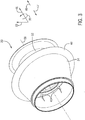
- FIG. 3 is a perspective view illustrating an embodiment of the gas turbine exhaust diffuser 30.
- the outer shell 34 may simultaneously extend in the axial direction 31 and radial direction 33 relative to the longitudinal axis 39 of the diffuser 20.
- the outer lip 48 may be curved, extending in the axial 31 and radial direction 33 relative to the longitudinal axis 39.
- the outer lip 48 may be linear, extending in the axial 31 and radial direction 33 relative to the longitudinal axis 39.
- the outer lip 48 may take on a tubular shape, extending in the circumferential direction 35 relative to the longitudinal axis 39.
- FIG. 4 is a cross-sectional view illustrating an embodiment of an asymmetric gas turbine exhaust diffuser 20 partially disposed in an exhaust collector 30.
- FIG. 4 may be a side view.
- FIG. 4 may be a top view.
- the diffuser 20 extends into the collector 30 in the axial direction 31 relative to the longitudinal axis 39 from the front wall 40 of the collector 30 toward the downstream 49 end of the collector 30.
- the diffuser 20 includes an inner shell 32 and an outer shell 34 that may define an inner wall 54 and an outer wall 56, respectively.
- the exhaust collector 30 extends a longitudinal length 58 relative to the axial direction 31.
- the inner shell 32 extends may extend a portion of or all of the longitudinal length 58 from the front wall 40 to the back wall 42.
- the outer shell 34 extends a portion of longitudinal length 58 in the circumferential direction 35 about the inner shell 32.
- the outer wall 56 may be linear, extending in the axial 31 and radial 33 direction relative to the longitudinal axis 39.
- the outer wall 56 may extend in a curved direction inward toward the longitudinal axis 39 or away from the longitudinal axis 39 from the upstream 47 end to the downstream 49 end.
- the inner wall 54 and the outer wall 56 may both be conical in shape extending circumferentially 35 in the axial direction 31 with respect to the longitudinal axis 39 with the outer wall 56 circumferentially disposed about the inner wall 54 along a portion of the longitudinal length 58.
- Exhaust may flow, as indicated by arrows 53, in through an inlet 50. Exhaust may then flow out through an outlet 51, into the exhaust collector 30. Exhaust may then flow out of the exhaust collector exit 52, as indicated by exhaust flow 44.
- the inlet 50 may be generally located between the upstream 47 end of the outer wall 56 and the upstream 47 end of the inner wall 54.
- the outlet 51 may be generally located between the inner wall 54 and a downstream 49 end of the outer wall 56.
- the gas turbine exhaust diffuser 20 includes a first lateral side 37 and a second lateral side 55 relative to the longitudinal axis 39 from a perspective as is generally seen in FIG. 4.
- the outer wall 56 is asymmetrically shaped so that an opening between the outlet 51 and the back wall 42 is larger in the first opening 36 than in the second opening 38.
- the distances between the openings 36, 38 and the back wall 42 can be seen in the first opening length 61 and the second opening length 62, respectively.
- the first opening length 61 may be approximately 30% larger than the second opening length 62.
- the first opening length 61 may be between approximately 25% and 60% greater, more than approximately 50% greater, approximately 20% greater, or approximately 40% greater than the second opening length 62.
- the asymmetry of the diffuser 20 can also be expressed through an angle 64.
- the asymmetry can also be defined by other angles too, depending on the reference point.
- the angle 64 can be seen between a first line 66 and a second line 68.
- the first line 66 extends from the downstream 49 end of the outer wall 56 on the second lateral side 55 to the downstream 49 end of the outer wall 56 on the first lateral side 37.
- the second line 68 is perpendicular to the longitudinal axis 39 of the diffuser 20 and may intersect the first line 66 on the downstream 49 end of the outer wall 56 on the second lateral side 55.
- a complimentary angle 70 to the angle 64 may be formed.
- the complimentary angle 70 may be the smallest angle between the first line 66 and the longitudinal axis 39.
- the angle 64 may also be seen between the longitudinal axis 39 and a third line 72.
- the third line 72 may be a normal line relative to the first line 66 and intersect the first line 66 at the longitudinal axis 39 to form the angle 64.
- the angle 64 may be greater than 0 degrees, greater than 5 degrees, or between 5 and 20 degrees. Consequently, the complimentary angle 70 may be greater than 0 degrees and less than 90 degrees, less than 85 degrees, or between 70 and 85 degrees.
- the diffuser 20, may not include struts 46.
- the diffuser 20 may contain at least one strut 46, between 2 and 8 struts 46, less than 10 struts, less than 20 struts 46, or between 4 and 16 struts 46.
- the cross-section of the strut(s) 46 may be for example, but is not limited to, rectilinear, circular, oval, or airfoil.
- the outer lip 48 is in the form of a curved wall 74 extending in both the axial direction 31 and the radial direction 33 relative to the longitudinal axis 39.
- FIG. 5 may be as described above in regard to FIG. 4 except that the outer lip 48 is in the form of a linear wall 76 extending linearly in both the axial direction 31 and the radial direction 33 relative to the longitudinal axis 39.
- FIG. 6 may be as described above in regard to FIG. 4 except that the outer lip 48 is in the form of a tubular structure 78 extending circumferentially 35 on the downstream 49 end of the outer lip 48.
- the embodiment depicted in FIG. 6 is an example of an embodiment where strut(s) 46 are not present. However, in other embodiments there may more one or more strut(s) 46 as described in greater detail above.
- FIG. 7 may be as described above in regard to FIG. 4 except that in this embodiment, there is no outer lip 48 disposed on a downstream 49 end of the outer wall 56.
- asymmetric gas turbine exhaust diffuser in which the outlet of the diffuser on the side of the exhaust collector's outlet is larger than on the opposite side of the diffuser.
- the asymmetric gas turbine exhaust diffuser will provide for better overall performance (e.g., improved pressure recovery factor, less total pressure loss, etc.) of the exhaust system of the gas turbine engine relative to conventional turbine exhaust systems.
- the asymmetric gas turbine exhaust diffuser will result in less back pressure, enable a reduction of the exhaust collector size without a reduction in performance, and does not have a need for turning vanes.
Landscapes
- Engineering & Computer Science (AREA)
- Mechanical Engineering (AREA)
- General Engineering & Computer Science (AREA)
- Chemical & Material Sciences (AREA)
- Combustion & Propulsion (AREA)
- Supercharger (AREA)
Priority Applications (2)
| Application Number | Priority Date | Filing Date | Title |
|---|---|---|---|
| EP17461507.0A EP3354868A1 (de) | 2017-01-30 | 2017-01-30 | Asymmetrischer gasturbinenabgasdiffusor |
| US15/438,996 US10550729B2 (en) | 2017-01-30 | 2017-02-22 | Asymmetric gas turbine exhaust diffuser |
Applications Claiming Priority (1)
| Application Number | Priority Date | Filing Date | Title |
|---|---|---|---|
| EP17461507.0A EP3354868A1 (de) | 2017-01-30 | 2017-01-30 | Asymmetrischer gasturbinenabgasdiffusor |
Publications (1)
| Publication Number | Publication Date |
|---|---|
| EP3354868A1 true EP3354868A1 (de) | 2018-08-01 |
Family
ID=57914926
Family Applications (1)
| Application Number | Title | Priority Date | Filing Date |
|---|---|---|---|
| EP17461507.0A Pending EP3354868A1 (de) | 2017-01-30 | 2017-01-30 | Asymmetrischer gasturbinenabgasdiffusor |
Country Status (2)
| Country | Link |
|---|---|
| US (1) | US10550729B2 (de) |
| EP (1) | EP3354868A1 (de) |
Cited By (2)
| Publication number | Priority date | Publication date | Assignee | Title |
|---|---|---|---|---|
| CN109630219A (zh) * | 2018-12-16 | 2019-04-16 | 中国航发沈阳发动机研究所 | 一种燃气轮机排气装置 |
| US11598224B2 (en) | 2020-06-15 | 2023-03-07 | General Electric Company | Exhaust collector conversion system and method |
Families Citing this family (2)
| Publication number | Priority date | Publication date | Assignee | Title |
|---|---|---|---|---|
| US10422344B1 (en) * | 2018-09-13 | 2019-09-24 | Borgwarner Inc. | Turbocharger turbine diffuser with deswirl ribs |
| DE102019101602A1 (de) * | 2019-01-23 | 2020-07-23 | Man Energy Solutions Se | Strömungsmaschine |
Citations (4)
| Publication number | Priority date | Publication date | Assignee | Title |
|---|---|---|---|---|
| WO1980000989A1 (en) * | 1978-11-10 | 1980-05-15 | Kh Politekn I | Exhaust pipe of turbine |
| US20090068006A1 (en) * | 2007-05-17 | 2009-03-12 | Elliott Company | Tilted Cone Diffuser for Use with an Exhaust System of a Turbine |
| US20090263241A1 (en) * | 2006-11-13 | 2009-10-22 | Alstom Technology Ltd | Diffuser and exhaust system for turbine |
| WO2014190095A1 (en) * | 2013-05-24 | 2014-11-27 | Solar Turbines Incorporated | Exhaust diffuser for a gas turbine engine exhaust system |
Family Cites Families (5)
| Publication number | Priority date | Publication date | Assignee | Title |
|---|---|---|---|---|
| US5188510A (en) * | 1990-11-21 | 1993-02-23 | Thomas R. Norris | Method and apparatus for enhancing gas turbo machinery flow |
| US5518366A (en) * | 1994-06-13 | 1996-05-21 | Westinghouse Electric Corporation | Exhaust system for a turbomachine |
| JP2961067B2 (ja) * | 1995-04-19 | 1999-10-12 | 三菱重工業株式会社 | 船舶用ガスタービンの排気装置 |
| DE102011003882A1 (de) * | 2011-02-09 | 2012-08-09 | Sb Limotive Company Ltd. | Zusammensetzung zum Löschen und/oder Hemmen von Fluor- und/oder Phosphor-haltigen Bränden |
| US9644496B2 (en) * | 2013-03-13 | 2017-05-09 | General Electric Company | Radial diffuser exhaust system |
-
2017
- 2017-01-30 EP EP17461507.0A patent/EP3354868A1/de active Pending
- 2017-02-22 US US15/438,996 patent/US10550729B2/en active Active
Patent Citations (4)
| Publication number | Priority date | Publication date | Assignee | Title |
|---|---|---|---|---|
| WO1980000989A1 (en) * | 1978-11-10 | 1980-05-15 | Kh Politekn I | Exhaust pipe of turbine |
| US20090263241A1 (en) * | 2006-11-13 | 2009-10-22 | Alstom Technology Ltd | Diffuser and exhaust system for turbine |
| US20090068006A1 (en) * | 2007-05-17 | 2009-03-12 | Elliott Company | Tilted Cone Diffuser for Use with an Exhaust System of a Turbine |
| WO2014190095A1 (en) * | 2013-05-24 | 2014-11-27 | Solar Turbines Incorporated | Exhaust diffuser for a gas turbine engine exhaust system |
Cited By (3)
| Publication number | Priority date | Publication date | Assignee | Title |
|---|---|---|---|---|
| CN109630219A (zh) * | 2018-12-16 | 2019-04-16 | 中国航发沈阳发动机研究所 | 一种燃气轮机排气装置 |
| US11598224B2 (en) | 2020-06-15 | 2023-03-07 | General Electric Company | Exhaust collector conversion system and method |
| US11873728B2 (en) | 2020-06-15 | 2024-01-16 | Ge Infrastructure Technology Llc | Exhaust collector conversion system and method |
Also Published As
| Publication number | Publication date |
|---|---|
| US20180216495A1 (en) | 2018-08-02 |
| US10550729B2 (en) | 2020-02-04 |
Similar Documents
| Publication | Publication Date | Title |
|---|---|---|
| US8757969B2 (en) | Turbine exhaust plenum | |
| US10502231B2 (en) | Diffuser pipe with vortex generators | |
| US20120034064A1 (en) | Contoured axial-radial exhaust diffuser | |
| US8109720B2 (en) | Exhaust plenum for a turbine engine | |
| US8234872B2 (en) | Turbine air flow conditioner | |
| US10550729B2 (en) | Asymmetric gas turbine exhaust diffuser | |
| US9422864B2 (en) | Staggered double row, slotted airfoil design for gas turbine exhaust frame | |
| US20120198810A1 (en) | Strut airfoil design for low solidity exhaust gas diffuser | |
| US9644496B2 (en) | Radial diffuser exhaust system | |
| JP7237444B2 (ja) | 排気ディフューザ | |
| US20160090901A1 (en) | Compressor inlet recirculation system for a turbocharger | |
| EP2584155A2 (de) | Abgasdiffusor | |
| US20130170969A1 (en) | Turbine Diffuser | |
| CN106907185B (zh) | 用于控制副流和最佳扩散器性能的凸出喷嘴 | |
| CA3166702A1 (en) | Diffuser pipe with curved cross-sectional shapes | |
| US10323528B2 (en) | Bulged nozzle for control of secondary flow and optimal diffuser performance | |
| US9670846B2 (en) | Enhanced mixing tube elements | |
| US20180258778A1 (en) | Non-axially symmetric transition ducts for combustors |
Legal Events
| Date | Code | Title | Description |
|---|---|---|---|
| PUAI | Public reference made under article 153(3) epc to a published international application that has entered the european phase |
Free format text: ORIGINAL CODE: 0009012 |
|
| STAA | Information on the status of an ep patent application or granted ep patent |
Free format text: STATUS: THE APPLICATION HAS BEEN PUBLISHED |
|
| AK | Designated contracting states |
Kind code of ref document: A1 Designated state(s): AL AT BE BG CH CY CZ DE DK EE ES FI FR GB GR HR HU IE IS IT LI LT LU LV MC MK MT NL NO PL PT RO RS SE SI SK SM TR |
|
| AX | Request for extension of the european patent |
Extension state: BA ME |
|
| STAA | Information on the status of an ep patent application or granted ep patent |
Free format text: STATUS: REQUEST FOR EXAMINATION WAS MADE |
|
| 17P | Request for examination filed |
Effective date: 20190201 |
|
| RAV | Requested validation state of the european patent: fee paid |
Extension state: MD Effective date: 20190201 Extension state: MA Effective date: 20190201 |
|
| RAX | Requested extension states of the european patent have changed |
Extension state: ME Payment date: 20190201 Extension state: BA Payment date: 20190201 |
|
| RBV | Designated contracting states (corrected) |
Designated state(s): AL AT BE BG CH CY CZ DE DK EE ES FI FR GB GR HR HU IE IS IT LI LT LU LV MC MK MT NL NO PL PT RO RS SE SI SK SM TR |
|
| STAA | Information on the status of an ep patent application or granted ep patent |
Free format text: STATUS: EXAMINATION IS IN PROGRESS |
|
| 17Q | First examination report despatched |
Effective date: 20200408 |
|
| STAA | Information on the status of an ep patent application or granted ep patent |
Free format text: STATUS: EXAMINATION IS IN PROGRESS |
|
| STAA | Information on the status of an ep patent application or granted ep patent |
Free format text: STATUS: EXAMINATION IS IN PROGRESS |
|
| RAP1 | Party data changed (applicant data changed or rights of an application transferred) |
Owner name: GENERAL ELECTRIC TECHNOLOGY GMBH |