EP3354614A1 - Automatic door switch inspection - Google Patents
Automatic door switch inspection Download PDFInfo
- Publication number
- EP3354614A1 EP3354614A1 EP18153466.0A EP18153466A EP3354614A1 EP 3354614 A1 EP3354614 A1 EP 3354614A1 EP 18153466 A EP18153466 A EP 18153466A EP 3354614 A1 EP3354614 A1 EP 3354614A1
- Authority
- EP
- European Patent Office
- Prior art keywords
- voltage
- landing
- door switch
- landing door
- switch
- Prior art date
- Legal status (The legal status is an assumption and is not a legal conclusion. Google has not performed a legal analysis and makes no representation as to the accuracy of the status listed.)
- Granted
Links
Images



Classifications
-
- B—PERFORMING OPERATIONS; TRANSPORTING
- B66—HOISTING; LIFTING; HAULING
- B66B—ELEVATORS; ESCALATORS OR MOVING WALKWAYS
- B66B5/00—Applications of checking, fault-correcting, or safety devices in elevators
- B66B5/0006—Monitoring devices or performance analysers
- B66B5/0018—Devices monitoring the operating condition of the elevator system
- B66B5/0025—Devices monitoring the operating condition of the elevator system for maintenance or repair
-
- B—PERFORMING OPERATIONS; TRANSPORTING
- B66—HOISTING; LIFTING; HAULING
- B66B—ELEVATORS; ESCALATORS OR MOVING WALKWAYS
- B66B5/00—Applications of checking, fault-correcting, or safety devices in elevators
- B66B5/0087—Devices facilitating maintenance, repair or inspection tasks
-
- B—PERFORMING OPERATIONS; TRANSPORTING
- B66—HOISTING; LIFTING; HAULING
- B66B—ELEVATORS; ESCALATORS OR MOVING WALKWAYS
- B66B5/00—Applications of checking, fault-correcting, or safety devices in elevators
- B66B5/0006—Monitoring devices or performance analysers
- B66B5/0018—Devices monitoring the operating condition of the elevator system
- B66B5/0031—Devices monitoring the operating condition of the elevator system for safety reasons
-
- B—PERFORMING OPERATIONS; TRANSPORTING
- B66—HOISTING; LIFTING; HAULING
- B66B—ELEVATORS; ESCALATORS OR MOVING WALKWAYS
- B66B13/00—Doors, gates, or other apparatus controlling access to, or exit from, cages or lift well landings
- B66B13/22—Operation of door or gate contacts
-
- B—PERFORMING OPERATIONS; TRANSPORTING
- B66—HOISTING; LIFTING; HAULING
- B66B—ELEVATORS; ESCALATORS OR MOVING WALKWAYS
- B66B5/00—Applications of checking, fault-correcting, or safety devices in elevators
- B66B5/0006—Monitoring devices or performance analysers
- B66B5/0037—Performance analysers
-
- G—PHYSICS
- G01—MEASURING; TESTING
- G01R—MEASURING ELECTRIC VARIABLES; MEASURING MAGNETIC VARIABLES
- G01R19/00—Arrangements for measuring currents or voltages or for indicating presence or sign thereof
- G01R19/165—Indicating that current or voltage is either above or below a predetermined value or within or outside a predetermined range of values
- G01R19/16504—Indicating that current or voltage is either above or below a predetermined value or within or outside a predetermined range of values characterised by the components employed
- G01R19/16509—Indicating that current or voltage is either above or below a predetermined value or within or outside a predetermined range of values characterised by the components employed using electromagnetic relays, e.g. reed relay
-
- G—PHYSICS
- G01—MEASURING; TESTING
- G01R—MEASURING ELECTRIC VARIABLES; MEASURING MAGNETIC VARIABLES
- G01R31/00—Arrangements for testing electric properties; Arrangements for locating electric faults; Arrangements for electrical testing characterised by what is being tested not provided for elsewhere
- G01R31/327—Testing of circuit interrupters, switches or circuit-breakers
- G01R31/3277—Testing of circuit interrupters, switches or circuit-breakers of low voltage devices, e.g. domestic or industrial devices, such as motor protections, relays, rotation switches
- G01R31/3278—Testing of circuit interrupters, switches or circuit-breakers of low voltage devices, e.g. domestic or industrial devices, such as motor protections, relays, rotation switches of relays, solenoids or reed switches
Definitions
- the present invention relates generally to an elevator system.
- the present invention relates to a detection of an abnormal condition of a door switch used in an elevator.
- the present invention provides a door switch inspection device and method of detecting an abnormal condition of a landing door switch for an elevator.
- an elevator system includes a plurality of door interlocks installed on landing doors at their respective landing floors. These door interlocks are configured to be released by mechanically interlocking with an elevator car door when the elevator car door is open on arrival of the elevator car at their respective landing floors. With such a configuration, not only can landing doors at the landing floors be prevented from being opened improperly from the outside, but the operation of the elevator car can be interrupted appropriately even if a landing door was opened, thereby unforeseen accidents can be avoided in advance.
- Such a door interlock is usually provided with a landing door switch for detecting a locked state and an unlocked state of the door interlock, and a switch contact of the landing door switch is opened and closed in conjunction with the opening and closing of the door interlock.
- Each landing door switch is connected in series with each other and with a relay coil of a door close detection relay.
- the door close detection relay is configured such that a relay contact of the door close detection relay is closed only when all the landing door switches are closed, followed by sending a signal indicative of the closed state of all the door switches to the elevator control device to properly operate the elevator car.
- a door switch inspection device for detecting an abnormal condition of a landing door switch used in an elevator.
- Each of a plurality of landing door switches is disposed on a corresponding landing door at each landing floor for detecting an open and a closed state of the landing door.
- Each of the plurality of landing door switches is connected in series with each other and with a relay coil of a door switch relay between power supply and ground.
- the door switch inspection device includes a plurality of voltage detection units connected to the ground side of their respective landing door switches for detecting a voltage value of their respective landing door switches in the closed state of all the landing door switches, and a switch contact monitoring unit connected to the plurality of voltage detection units for detecting an abnormal condition of a landing door switch.
- the switch contact monitoring unit is configured to calculate a voltage difference between two voltage values obtained from a landing floor and an adjacent upper floor with respect to all floors, compare the voltage difference with a threshold voltage, and detect the abnormal condition of the landing door switch at the landing floor if the voltage difference exceeds the threshold voltage.
- the abnormal condition of the landing door switch at the highest floor is determined by calculating a voltage difference between the voltage value obtained from the highest floor and the power supply voltage and comparing the voltage difference with the threshold value.
- each of the plurality of voltage detection units is included in a hall station disposed at each landing floor.
- the switch contact monitoring unit is included in a main controller for an elevator system.
- the threshold voltage is predetermined based on the number of floors in a building, the power supply voltage to be applied and the resistance value of the door switch relay.
- the voltage value is an analog input voltage detected by the voltage detection unit.
- the switch contact monitoring unit transmits an alert to inspect the switch contact of the landing door switch at the landing floor if the voltage difference exceeds the threshold voltage.
- a method of detecting an abnormal condition of a landing door switch for an elevator is disclosed.
- Each of a plurality of landing door switches is disposed on a corresponding landing door at each landing floor for detecting an open and a closed state of the landing door.
- Each of the plurality of landing door switches are connected in series with each other and with a relay coil of a door switch relay between power supply and ground.
- the method of detecting an abnormal condition of a landing door switch for an elevator includes obtaining a voltage value of each landing door switch with respect to all floors in the closed state of all the landing door switches, calculating a voltage difference between two voltage values obtained from a landing floor and an adjacent upper floor with respect to all floors, comparing the voltage difference with a threshold voltage, and detecting the abnormal condition of the landing door switch at the landing floor if the voltage difference exceeds the threshold voltage.
- obtaining the voltage value further comprises obtaining the voltage value from the ground side of each landing door switch.
- calculating the voltage difference further comprises calculating a voltage difference between the voltage value obtained from the highest floor and the power supply voltage.
- the threshold voltage is predetermined based on the number of floors in a building, the power supply voltage to be applied and the resistance value of the door switch relay.
- the voltage value is an analog input voltage.
- the method further includes transmitting an alert to inspect the switch contact of the landing door switch at the landing floor if the voltage difference exceeds the threshold voltage.
- FIG. 1 shows an example of a door interlock 1 in accordance with the present invention installed on a landing door at each landing floor.
- each door interlock 1 includes a latch member 2 which is pivotably mounted on the upper portion of one side of a set of double-doors (not shown), and a receiver 3 mounted on the other side of the double-doors in proximity to the latch member 2 for receiving the corresponding latch member 2 when it is latched.
- the latch member 2 engages the receiver 3 when the door is closed, thereby preventing the landing door from being opened intentionally from the outside in such a case when the elevator car is not at the landing.
- each door interlock 1 is equipped with a corresponding landing door switch 4.
- the landing door switch 4 includes two switch contacts 5, 5 each having a spring contact 6 mounted on a leaf spring, and a bridging contact 7 configured to electrically connect or "bridge” two switch contacts 5, 5 when it is biased against the switch contacts 5, 5.
- two switch contacts 5, 5 are mounted, for example, on the receiver 3, and the bridging contact 7 is mounted on the latch member 2 so as to bridge two switch contacts 5, 5 when the latch member 2 is latched upon elevator door closing.
- the landing door switch 4 is configured such that when the elevator door is closed ( FIG.
- two switch contacts 5, 5 are electrically connected to each other via the bridging contact 7 to be set in ON, and when the door is open ( FIG. 1B ), two switch contacts 5, 5 are released from the bridging contact 7 in response to the disengagement of the latch member 2 to be set in OFF.
- the landing door switches 4 disposed on landing doors at their respective landing floors are, as described later, connected in series with each other with respect to a door close detection relay 8 that is electrically connected to a main controller 9.
- the main controller 9 is configured to operate the elevator car only when the main controller 9 detects that all the landing door switches 4 are closed with respect to the door close detection relay 8 (i.e. when all the lading door switches are ON).
- the structure of the present invention is not limited to the door interlock as described above with reference to FIG. 1 , but the present invention may include any door interlock capable of implementing the door switch monitoring device described herein. It should also be understood that the landing door switch is not limited to a spring contact as described above, but may include any known types of landing door switches.
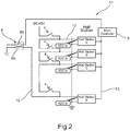
- FIG. 2 illustrates a voltage monitoring wiring diagram of the landing door switches 4 installed on landing doors at their respective landing floors in accordance with an embodiment the present invention, for detecting an abnormal condition between the switch contacts 5, 5 and the bridging contact 7.
- the landing door switches (DS) 4 disposed on landing doors at their respective landing floors are connected in series with each other between power supply (e.g. DC 48V) and ground, and a door close detection relay 8 is provided between the door switch 4 at the lowest landing floor and ground.
- the door close detection relay 8 has a relay coil 8a and a relay contact 8b, and each landing door switch 4 is connected in series with each other with respect to the relay coil 8a of the door close detection relay 8.
- the relay contact 8b of the door close detection relay 8 is electrically connected to a main controller 9 and is set to be closed in response to a closed state detection of all the landing door switches 4. Subsequently, the relay contact 8b sends a signal indicative of the closed state detection signal of all the landing door switches 4 to the main controller 9 to operate the elevator car.
- the relay contact 8b of the door close detection relay 8 is opened accordingly, and the main controller 9 stops operation of the elevator car until it receives closed state detection of all the landing door switches 4 from the door close detection relay 8.
- a landing door switch voltage monitoring wiring 11 connected to the landing door switches 4 is described, as an example of a door switch inspection device.
- Hall stations A, B, C, ..., N are connected to their respective door switches 4 at their respective landing floors.
- an analog voltage input line 12 drawn from ground side of each door switch 4 is connected to a corresponding hall station A, B, C, ..., N.
- the hall stations A, B, C, ..., N are connected to the main controller 9 via control lines 13.
- Each hall station A, B, C, ..., N is configured as a voltage detection unit to obtain voltage value (analog input voltage) at a corresponding switch contact of each landing door switch 4 arranged on each landing floor, and transmit the voltage value to the main controller 9 in response to a request.
- the main controller 9 is generally provided with a control circuit for dispatching elevator cars, group management control, elevator safety control, etc., and also provided with a door switch contact monitoring circuit for carrying out an abnormal condition detection algorithm which detects a contact failure of a landing door switch as described below.
- the hall stations A, B, C, ..., N provided on their respective landing floors generally have their respective hall call buttons and are configured to transmit a hall call to the main controller 9, in addition to the detection of voltage values at their respective switch contacts of the landing door switches 4.
- FIG. 3 illustrates a flow diagram 100 of detecting a voltage value (analog input voltage) at each switch contact of a corresponding landing door switch 4 disposed at each landing floor.
- operation starts from checking the status of door close detection relay 8 as shown in FIG. 2 .
- the door close detection relay 8 detects that all the landing door switches 4 are closed (i.e. all the door switches 4 are ON)
- the main controller 9 sends a request to a hall station X to obtain an input voltage (ADI X) of a landing door switch 4.
- the input voltage value (ADI X) derived from this algorithm 100 is stored in a memory (not shown) and then proceeds to step 104.
- the main controller 9 checks to see if the count value "X" reaches to "N" (step 104). If the count value "X" does not reach to "N", i.e., if the main controller does not obtain input voltage values from all the hall stations A, B, ..., N, then the algorithm increments the count "X” by one (step 105) and returns to step 103 to repeat process. This loop continues until all the input voltage values of the landing door switches 4 are obtained.
- step 104 the main controller 9 then proceeds to the algorithm in FIG. 4 which determines an abnormal condition at a contact point of a landing door switch 4.
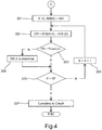
- FIG. 4 illustrates a flow diagram 200 of the detection algorithm of an abnormal condition at a contact point of a landing door switch 4.
- operation starts from setting the count value "X" to zero (0) and the power supply voltage, ADI(0) (e.g. setting to DC 48V), and proceeds to step 202.
- voltage (ADI(X)) at step 202 refers to a voltage value of a corresponding landing door switch 4 detected by the hall station X.
- the voltage difference between the voltage value from the top floor and the power supply voltage derived at step 202 is compared with a threshold value.
- the threshold value is a predetermined voltage value which may be set by taking into consideration the number of the floors in a building, the power supply voltage to be applied, resistance values of relays, etc. If the voltage difference is less than the threshold value, then the status of the switch contact of the door switch 4 at the highest floor which is detected by the hall station A, is determined to be in a normal condition, and then proceeds to step 205.
- the main controller 9 determines that an abnormal condition occurs at the switch contact of the door switch 4 at the highest floor (step 204), and the main controller 9 may additionally transmit a warning to a maintenance person to inspect the switch contact of the door switch 4 at the highest floor, followed by proceeding to step 205.
- the warning signal may be transmitted to a maintenance person or a building administrative company via any means known in the prior art, including, but not limited to, internet, fixed lines, etc.
- step 207 By comparing the voltage difference with the threshold voltage value, an abnormal voltage drop across any door switch 4 can be easily detected. This voltage drop is generally caused by an increase in resistance observed at the switch contact of a door switch 4, which can be generated by the adhesion of the dust, corrosions, aged deteriorations or the like.
- the algorithm 200 completes and returns to step 101 ( FIG. 3 ) to repeat process.
- the detection mechanism in accordance with this embodiment is installed in a building with five stories above, and an abnormal condition has occurred in a landing door switch 4 at the third floor.
- the resistance value at the door switch contact is usually 1 ohm ( ⁇ ) and the resistance value at the door switch contact having abnormal condition (at the third floor) is 20 ohms.
- the threshold value of the voltage difference is set to 2.0V.
- the power supply voltage is DC 48V and the resistance value of the relay coil is 330 ohms.
- the analog input voltages at their respective switch contacts of the landing door switches 4 are obtained by the hall stations A, B, C, D and E in response to a request from the main controller 9, and these voltage values are shown in the first row of the table shown in FIG. 5(B) .
- the voltage difference between two voltage values obtained from an upper floor and an adjacent lower floor is calculated subsequently by executing the algorithm shown in FIG. 4 .
- These results are shown in the second row of the table in FIG. 5(B) .
- the present invention is characterized in that an abnormal condition across a switch contact of a landing door switch is detected by comparing a voltage drop value across the switch contact of the landing door switch (i.e., a difference between two voltage values detected at the landing floor and at an adjacent upper floor) and a predetermined threshold voltage.
- an automatic door switch inspection system using a simple control algorithm as described with reference to FIGS. 3 and 4 , it is capable of detecting which landing door switch has an abnormal condition associated with dust adhesions to switch contacts, corrosions of contacts, aged deteriorations, etc., thereby remarkably reducing a burden on a maintenance person when a periodical inspection is performed.
- the door switch inspection device in accordance with embodiments of the present invention has an algorithm implementable on an existing main controller and hall stations, it can also be easily retrofitted to existing elevator systems.
Landscapes
- Physics & Mathematics (AREA)
- General Physics & Mathematics (AREA)
- Electromagnetism (AREA)
- Elevator Door Apparatuses (AREA)
- Maintenance And Inspection Apparatuses For Elevators (AREA)
Abstract
Description
- The present invention relates generally to an elevator system. In particular, the present invention relates to a detection of an abnormal condition of a door switch used in an elevator. The present invention provides a door switch inspection device and method of detecting an abnormal condition of a landing door switch for an elevator.
- In general, an elevator system includes a plurality of door interlocks installed on landing doors at their respective landing floors. These door interlocks are configured to be released by mechanically interlocking with an elevator car door when the elevator car door is open on arrival of the elevator car at their respective landing floors. With such a configuration, not only can landing doors at the landing floors be prevented from being opened improperly from the outside, but the operation of the elevator car can be interrupted appropriately even if a landing door was opened, thereby unforeseen accidents can be avoided in advance.
- Such a door interlock is usually provided with a landing door switch for detecting a locked state and an unlocked state of the door interlock, and a switch contact of the landing door switch is opened and closed in conjunction with the opening and closing of the door interlock. Each landing door switch is connected in series with each other and with a relay coil of a door close detection relay. The door close detection relay is configured such that a relay contact of the door close detection relay is closed only when all the landing door switches are closed, followed by sending a signal indicative of the closed state of all the door switches to the elevator control device to properly operate the elevator car.
- On the other hand, in such a landing door switch, it is known that a poor contact may occur due to dust adhesions to a switch contact, contact corrosions, aged deteriorations, etc. In a case when a periodical inspection is performed, a maintenance person has to inspect all the door interlocks manually (and the landing door switches as well). In particular, when the elevator system is installed in a high-rise building, the number of door interlocks to be checked increases and it takes more time for inspection, and thus there is a disadvantage of increasing a burden on the maintenance person.
- Furthermore, even if there is a poor contact in only one of the landing door switches, it is not only necessary to examine all of the door interlocks (and the landing door switches accordingly), but is necessary to identify whether a specific door interlock itself is in an abnormal condition or a lading door switch has a contact failure. In such a case, it requires much more time to recover the entire elevator system.
- Therefore, there exists in the art a need for providing a door switch inspection device, capable of not only detecting abnormal conditions in a landing door switch, but also identifying on which landing door switch a poor electrical contact occurs in advance of failure.
- According to one aspect of the present invention, a door switch inspection device for detecting an abnormal condition of a landing door switch used in an elevator is disclosed. Each of a plurality of landing door switches is disposed on a corresponding landing door at each landing floor for detecting an open and a closed state of the landing door. Each of the plurality of landing door switches is connected in series with each other and with a relay coil of a door switch relay between power supply and ground. The door switch inspection device includes a plurality of voltage detection units connected to the ground side of their respective landing door switches for detecting a voltage value of their respective landing door switches in the closed state of all the landing door switches, and a switch contact monitoring unit connected to the plurality of voltage detection units for detecting an abnormal condition of a landing door switch.
- The switch contact monitoring unit according to the present invention is configured to calculate a voltage difference between two voltage values obtained from a landing floor and an adjacent upper floor with respect to all floors, compare the voltage difference with a threshold voltage, and detect the abnormal condition of the landing door switch at the landing floor if the voltage difference exceeds the threshold voltage.
- In some embodiments, the abnormal condition of the landing door switch at the highest floor is determined by calculating a voltage difference between the voltage value obtained from the highest floor and the power supply voltage and comparing the voltage difference with the threshold value.
- In some embodiments, in addition or alternatively, each of the plurality of voltage detection units is included in a hall station disposed at each landing floor.
- In some embodiments, in addition or alternatively, the switch contact monitoring unit is included in a main controller for an elevator system.
- In some embodiments, in addition or alternatively, the threshold voltage is predetermined based on the number of floors in a building, the power supply voltage to be applied and the resistance value of the door switch relay.
- In some embodiments, in addition or alternatively, the voltage value is an analog input voltage detected by the voltage detection unit.
- In some embodiments, in addition or alternatively, the switch contact monitoring unit transmits an alert to inspect the switch contact of the landing door switch at the landing floor if the voltage difference exceeds the threshold voltage.
- According to another aspect of the present invention, a method of detecting an abnormal condition of a landing door switch for an elevator is disclosed. Each of a plurality of landing door switches is disposed on a corresponding landing door at each landing floor for detecting an open and a closed state of the landing door. Each of the plurality of landing door switches are connected in series with each other and with a relay coil of a door switch relay between power supply and ground. The method of detecting an abnormal condition of a landing door switch for an elevator includes obtaining a voltage value of each landing door switch with respect to all floors in the closed state of all the landing door switches, calculating a voltage difference between two voltage values obtained from a landing floor and an adjacent upper floor with respect to all floors, comparing the voltage difference with a threshold voltage, and detecting the abnormal condition of the landing door switch at the landing floor if the voltage difference exceeds the threshold voltage.
- In some embodiments, obtaining the voltage value further comprises obtaining the voltage value from the ground side of each landing door switch.
- In some embodiments, in addition or alternatively, calculating the voltage difference further comprises calculating a voltage difference between the voltage value obtained from the highest floor and the power supply voltage.
- In some embodiments, in addition or alternatively, the threshold voltage is predetermined based on the number of floors in a building, the power supply voltage to be applied and the resistance value of the door switch relay.
- In some embodiments, in addition or alternatively, the voltage value is an analog input voltage.
- In some embodiments, in addition or alternatively, the method further includes transmitting an alert to inspect the switch contact of the landing door switch at the landing floor if the voltage difference exceeds the threshold voltage.
- These and other aspects of this disclosure will become more readily apparent from the following description and the accompanying drawings, which can be briefly described as follows.
-
-
Figure 1 is a schematic view showing one possible arrangement of a door interlock according to an embodiment of the present invention installed on a landing door at each landing floor. -
Figure 2 is a voltage monitoring wiring diagram of landing door switches installed on landing doors at their respective landing floors in accordance with an embodiment of the present invention, for detecting an abnormal condition of a landing door switch. -
Figure 3 is a flow diagram of detecting a voltage value at each switch contact of a corresponding landing door switch disposed at each landing floor. -
Figure 4 is a flow diagram of determining an abnormal condition at a contact point of a landing door switch. -
Figure 5 illustrates an example method of detecting a landing door switch having an abnormal condition using a detection algorithm according to embodiments of the present invention. -
Figure 1 shows an example of adoor interlock 1 in accordance with the present invention installed on a landing door at each landing floor. In one example, eachdoor interlock 1 includes alatch member 2 which is pivotably mounted on the upper portion of one side of a set of double-doors (not shown), and areceiver 3 mounted on the other side of the double-doors in proximity to thelatch member 2 for receiving thecorresponding latch member 2 when it is latched. As shown inFIG. 1(A) , thelatch member 2 engages thereceiver 3 when the door is closed, thereby preventing the landing door from being opened intentionally from the outside in such a case when the elevator car is not at the landing. - On the other hand, as shown in
FIG. 1(B) , when the elevator car arrives at the landing and the car door opens, thelatch member 2 disengages from thereceiver 3 by mechanically interlocking with the car door (not shown), and thereby thedoor interlock 1 is released. - Furthermore, each
door interlock 1 is equipped with a correspondinglanding door switch 4. As an example, thelanding door switch 4 includes twoswitch contacts spring contact 6 mounted on a leaf spring, and abridging contact 7 configured to electrically connect or "bridge" twoswitch contacts switch contacts FIG. 1 , twoswitch contacts receiver 3, and thebridging contact 7 is mounted on thelatch member 2 so as to bridge twoswitch contacts latch member 2 is latched upon elevator door closing. In particular, thelanding door switch 4 is configured such that when the elevator door is closed (FIG. 1A ), twoswitch contacts bridging contact 7 to be set in ON, and when the door is open (FIG. 1B ), twoswitch contacts bridging contact 7 in response to the disengagement of thelatch member 2 to be set in OFF. - The
landing door switches 4 disposed on landing doors at their respective landing floors are, as described later, connected in series with each other with respect to a doorclose detection relay 8 that is electrically connected to amain controller 9. Themain controller 9 is configured to operate the elevator car only when themain controller 9 detects that all thelanding door switches 4 are closed with respect to the door close detection relay 8 (i.e. when all the lading door switches are ON). - It should be understood that the structure of the present invention is not limited to the door interlock as described above with reference to
FIG. 1 , but the present invention may include any door interlock capable of implementing the door switch monitoring device described herein. It should also be understood that the landing door switch is not limited to a spring contact as described above, but may include any known types of landing door switches. -
Figure 2 illustrates a voltage monitoring wiring diagram of thelanding door switches 4 installed on landing doors at their respective landing floors in accordance with an embodiment the present invention, for detecting an abnormal condition between theswitch contacts bridging contact 7. As shown inFIG. 2 , the landing door switches (DS) 4 disposed on landing doors at their respective landing floors are connected in series with each other between power supply (e.g. DC 48V) and ground, and a doorclose detection relay 8 is provided between thedoor switch 4 at the lowest landing floor and ground. The doorclose detection relay 8 has arelay coil 8a and arelay contact 8b, and eachlanding door switch 4 is connected in series with each other with respect to therelay coil 8a of the doorclose detection relay 8. - Here, the
relay contact 8b of the doorclose detection relay 8 is electrically connected to amain controller 9 and is set to be closed in response to a closed state detection of all thelanding door switches 4. Subsequently, therelay contact 8b sends a signal indicative of the closed state detection signal of all thelanding door switches 4 to themain controller 9 to operate the elevator car. On the other hand, when the elevator car stops at a landing floor and the correspondinglanding door switch 4 is opened, therelay contact 8b of the doorclose detection relay 8 is opened accordingly, and themain controller 9 stops operation of the elevator car until it receives closed state detection of all the landing door switches 4 from the doorclose detection relay 8. - Next, a landing door switch
voltage monitoring wiring 11 connected to the landing door switches 4 is described, as an example of a door switch inspection device. - Hall stations A, B, C, ..., N are connected to their
respective door switches 4 at their respective landing floors. As shown inFIG. 2 , an analogvoltage input line 12 drawn from ground side of eachdoor switch 4 is connected to a corresponding hall station A, B, C, ..., N. The hall stations A, B, C, ..., N are connected to themain controller 9 via control lines 13. Each hall station A, B, C, ..., N is configured as a voltage detection unit to obtain voltage value (analog input voltage) at a corresponding switch contact of each landingdoor switch 4 arranged on each landing floor, and transmit the voltage value to themain controller 9 in response to a request. - Here, the
main controller 9 is generally provided with a control circuit for dispatching elevator cars, group management control, elevator safety control, etc., and also provided with a door switch contact monitoring circuit for carrying out an abnormal condition detection algorithm which detects a contact failure of a landing door switch as described below. - The hall stations A, B, C, ..., N provided on their respective landing floors generally have their respective hall call buttons and are configured to transmit a hall call to the
main controller 9, in addition to the detection of voltage values at their respective switch contacts of the landing door switches 4. -
Figure 3 illustrates a flow diagram 100 of detecting a voltage value (analog input voltage) at each switch contact of a correspondinglanding door switch 4 disposed at each landing floor. In this algorithm, operation starts from checking the status of doorclose detection relay 8 as shown inFIG. 2 . Atstep 101, once the doorclose detection relay 8 detects that all the landing door switches 4 are closed (i.e. all the door switches 4 are ON), the closed state detection signal of all the landing door switches 4 is sent to themain controller 9 to initiate detection of voltage value at each switch contact of a correspondinglanding door switch 4, followed by setting the count value "X" to one (X=1) (step 102) and then proceeds to step 103. It should be noted that "X" does not denote a floor number in a building, but it corresponds to the number of the hall stations as well as the landing door switches. For example, if this algorithm is carried out to a building with eight stories above and two below, the total number of the hall stations (i.e. the total number of the landing door switches) in the building, N, is ten, and each value, "X=1, 2, ..., N", corresponds to the landing door switch at the eighth floor, seventh floor, ..., and the basement second floor, respectively. In other words, "X=1, 2, ..., N" correspond respectively to the hall stations A, B, C, ..., N disposed from the highest floor to the lowest floor. - At
step 103, themain controller 9 sends a request to a hall station X to obtain an input voltage (ADI X) of alanding door switch 4. The input voltage value (ADI X) derived from this algorithm 100 is stored in a memory (not shown) and then proceeds to step 104. - Subsequently, the
main controller 9 checks to see if the count value "X" reaches to "N" (step 104). If the count value "X" does not reach to "N", i.e., if the main controller does not obtain input voltage values from all the hall stations A, B, ..., N, then the algorithm increments the count "X" by one (step 105) and returns to step 103 to repeat process. This loop continues until all the input voltage values of the landing door switches 4 are obtained. - When the count value "X" reaches to "N" (step 104), the
main controller 9 then proceeds to the algorithm inFIG. 4 which determines an abnormal condition at a contact point of alanding door switch 4. -
Figure 4 illustrates a flow diagram 200 of the detection algorithm of an abnormal condition at a contact point of alanding door switch 4. Atstep 201, operation starts from setting the count value "X" to zero (0) and the power supply voltage, ADI(0) (e.g. setting toDC 48V), and proceeds to step 202. Atstep 202, the voltage difference between the voltage value obtained from the top floor and the power supply voltage is calculated (Diff = ADI(1) - ADI(0)). Note that voltage (ADI(X)) atstep 202 refers to a voltage value of a correspondinglanding door switch 4 detected by the hall station X. Each voltage value is obtained from the algorithm 100 shown inFIG. 3 , where X=1, 2, ..., N correspond respectively to the hall stations A, B, C, ..., N disposed from the highest floor to the lowest floor. - At
step 203, the voltage difference between the voltage value from the top floor and the power supply voltage derived atstep 202 is compared with a threshold value. The threshold value is a predetermined voltage value which may be set by taking into consideration the number of the floors in a building, the power supply voltage to be applied, resistance values of relays, etc. If the voltage difference is less than the threshold value, then the status of the switch contact of thedoor switch 4 at the highest floor which is detected by the hall station A, is determined to be in a normal condition, and then proceeds to step 205. If the voltage difference exceeds the threshold value, then themain controller 9 determines that an abnormal condition occurs at the switch contact of thedoor switch 4 at the highest floor (step 204), and themain controller 9 may additionally transmit a warning to a maintenance person to inspect the switch contact of thedoor switch 4 at the highest floor, followed by proceeding to step 205. It should be understood that the warning signal may be transmitted to a maintenance person or a building administrative company via any means known in the prior art, including, but not limited to, internet, fixed lines, etc. - At
step 205, the main controller checks to see if the count value "X" reaches to "N". If the count value "X" does not reach to "N", then the algorithm increments the count "X" by one (step 206) and returns to step 202 to repeat process. Then, the voltage difference between two voltage values obtained from an upper floor and an adjacent lower floor (Diff = ADI(X+1) - ADI(X)) is obtained and compared with the threshold voltage value, subsequently. This loop continues until the voltage difference between two voltage values obtained from an upper floor and an adjacent lower floor is determined with respect to all floors, to see whether an abnormal condition occurs at any switch contact of adoor switch 4 at any floor. By comparing the voltage difference with the threshold voltage value, an abnormal voltage drop across anydoor switch 4 can be easily detected. This voltage drop is generally caused by an increase in resistance observed at the switch contact of adoor switch 4, which can be generated by the adhesion of the dust, corrosions, aged deteriorations or the like. Following the execution ofstep 207, the algorithm 200 completes and returns to step 101 (FIG. 3 ) to repeat process. - Next, with reference to
Figure 5 , a method of detecting alanding door switch 4 having an abnormality will be described using a detection mechanism as shown inFIG. 1 to FIG. 4 . - Assume that the detection mechanism in accordance with this embodiment is installed in a building with five stories above, and an abnormal condition has occurred in a
landing door switch 4 at the third floor. In this case, assume that the resistance value at the door switch contact is usually 1 ohm (Ω) and the resistance value at the door switch contact having abnormal condition (at the third floor) is 20 ohms. The threshold value of the voltage difference is set to 2.0V. The power supply voltage isDC 48V and the resistance value of the relay coil is 330 ohms. Although the hall stations A-E are connected via the analog voltage input lines A-E for monitoring a voltage difference, these current values are assumed to be infinitely close to zero since the impedance of these input lines is high. That is, the current values of the voltage input lines A-E can be neglected. - As described with reference to
FIG. 3 , the analog input voltages at their respective switch contacts of the landing door switches 4 are obtained by the hall stations A, B, C, D and E in response to a request from themain controller 9, and these voltage values are shown in the first row of the table shown inFIG. 5(B) . After obtaining the voltage values of the landing door switches 4 at all floors, the voltage difference between two voltage values obtained from an upper floor and an adjacent lower floor is calculated subsequently by executing the algorithm shown inFIG. 4 . These results are shown in the second row of the table inFIG. 5(B) . - As can be appreciated from
FIG. 5(B) , a voltage difference (2.80 V) exceeding the threshold voltage difference of 2.0 V is observed at the voltage input C. That is, since the voltage difference, Diff = ADI (3) - ADI (2) (step 202 as shown inFIG. 4 ), exceeds the threshold value, it is found that there is an abnormality occurred at the switch contact of the third door switch 4 (at the third floor). This voltage drop is generally caused by an increase in resistance observed at the switch contact of thethird door switch 4 arranged between the voltage input lines B and C, which can be generated by the adhesion of the dust, corrosions, aged deteriorations or the like. - The present invention is characterized in that an abnormal condition across a switch contact of a landing door switch is detected by comparing a voltage drop value across the switch contact of the landing door switch (i.e., a difference between two voltage values detected at the landing floor and at an adjacent upper floor) and a predetermined threshold voltage.
- According to embodiments of the present invention, by employing an automatic door switch inspection system using a simple control algorithm as described with reference to
FIGS. 3 and4 , it is capable of detecting which landing door switch has an abnormal condition associated with dust adhesions to switch contacts, corrosions of contacts, aged deteriorations, etc., thereby remarkably reducing a burden on a maintenance person when a periodical inspection is performed. - In particular, since the door switch inspection device in accordance with embodiments of the present invention has an algorithm implementable on an existing main controller and hall stations, it can also be easily retrofitted to existing elevator systems.
- While the present invention has been particularly shown and described with reference to the exemplary embodiments as illustrated in the drawings, it will be recognized by those skilled in the art that various modifications may be made without departing from the scope of the invention as disclosed in the accompanying claims.
Claims (13)
- A door switch inspection device for detecting an abnormal condition of a landing door switch used in an elevator, each of a plurality of landing door switches disposed on a corresponding landing door at each landing floor for detecting an open and a closed state of the landing door, each of the plurality of landing door switches connected in series with each other and with a relay coil of a door switch relay between power supply and ground, the door switch inspection device comprising:a plurality of voltage detection units connected to the ground side of their respective landing door switches for detecting an voltage value of their respective landing door switches in the closed state of all the landing door switches; anda switch contact monitoring unit connected to the plurality of voltage detection units for detecting an abnormal condition of a landing door switch,the switch contact monitoring unit configured to calculate a voltage difference between two voltage values obtained from a landing floor and an adjacent upper floor with respect to all floors, compare the voltage difference with a threshold voltage, and detect the abnormal condition of the landing door switch at the landing floor if the voltage difference exceeds the threshold voltage.
- The door switch inspection device of claim 1, wherein the abnormal condition of the landing door switch at the highest floor is determined by calculating a voltage difference between the voltage value obtained from the highest floor and the power supply voltage and comparing the voltage difference with the threshold value.
- The door switch inspection device of claim 1 or 2, wherein each of the plurality of voltage detection units is included in a hall station disposed at each landing floor.
- The door switch inspection device of any preceding claim, wherein the switch contact monitoring unit is included in a main controller for an elevator system.
- The door switch inspection device of any preceding claim , wherein the threshold voltage is predetermined based on the number of floors in a building, the power supply voltage to be applied and the resistance value of the door switch relay.
- The door switch inspection device of any preceding claim , wherein the voltage value is an analog input voltage detected by the voltage detection unit.
- The door switch inspection device of any preceding claim, wherein the switch contact monitoring unit transmits an alert to inspect the switch contact of the landing door switch at the landing floor if the voltage difference exceeds the threshold voltage.
- A method of detecting an abnormal condition of a landing door switch for an elevator, each of a plurality of landing door switches disposed on a corresponding landing door at each landing floor for detecting an open and a closed state of the landing door, each of the plurality of landing door switches connected in series with each other and with a relay coil of a door switch relay between power supply and ground, the method comprising:obtaining a voltage value of each landing door switch with respect to all floors in the closed state of all the landing door switches;calculating a voltage difference between two voltage values obtained from a landing floor and an adjacent upper floor with respect to all floors;comparing the voltage difference with a threshold voltage; anddetecting the abnormal condition of the landing door switch at the landing floor if the voltage difference exceeds the threshold voltage.
- The method of claim 8, wherein obtaining the voltage value further comprises obtaining the voltage value from the ground side of each landing door switch.
- The method of claim 8 or 9, wherein calculating the voltage difference further comprises calculating a voltage difference between the voltage value obtained from the highest floor and the power supply voltage.
- The method of any of claims 8-10, wherein the threshold voltage is predetermined based on the number of floors in a building, the power supply voltage to be applied and the resistance value of the door switch relay.
- The method of any of claims 8-11, wherein the voltage value is an analog input voltage.
- The method of any of claims 8-12, further comprising the step of transmitting an alert to inspect the switch contact of the landing door switch at the landing floor if the voltage difference exceeds the threshold voltage.
Applications Claiming Priority (1)
| Application Number | Priority Date | Filing Date | Title |
|---|---|---|---|
| US15/415,260 US10233053B2 (en) | 2017-01-25 | 2017-01-25 | Automatic door switch inspection |
Publications (2)
| Publication Number | Publication Date |
|---|---|
| EP3354614A1 true EP3354614A1 (en) | 2018-08-01 |
| EP3354614B1 EP3354614B1 (en) | 2023-04-05 |
Family
ID=61027573
Family Applications (1)
| Application Number | Title | Priority Date | Filing Date |
|---|---|---|---|
| EP18153466.0A Active EP3354614B1 (en) | 2017-01-25 | 2018-01-25 | Automatic door switch inspection |
Country Status (5)
| Country | Link |
|---|---|
| US (1) | US10233053B2 (en) |
| EP (1) | EP3354614B1 (en) |
| JP (1) | JP7086614B2 (en) |
| CN (1) | CN108341312B (en) |
| ES (1) | ES2942178T3 (en) |
Cited By (1)
| Publication number | Priority date | Publication date | Assignee | Title |
|---|---|---|---|---|
| EP3617114A1 (en) * | 2018-08-30 | 2020-03-04 | Inventio AG | Method and monitoring device for monitoring a safety chain circuit in a lift system |
Families Citing this family (12)
| Publication number | Priority date | Publication date | Assignee | Title |
|---|---|---|---|---|
| EP3401261B1 (en) * | 2017-05-12 | 2021-02-24 | Otis Elevator Company | Automatic elevator inspection systems and methods |
| CN110861984B (en) * | 2018-08-27 | 2021-01-29 | 广州广日电梯工业有限公司 | Monitoring method of elevator centering device and monitoring device of elevator centering device |
| US10636272B2 (en) * | 2018-09-26 | 2020-04-28 | Otis Elevator Company | Time domain reflectometry for electrical safety chain condition based maintenance |
| EP3650388B1 (en) * | 2018-11-06 | 2025-08-06 | KONE Corporation | A method and a system for detecting a malfunction of an elevator system |
| CN109879134B (en) * | 2019-04-09 | 2024-06-18 | 深圳市海浦蒙特科技有限公司 | High-voltage door lock detection circuit and method |
| CN110304515B (en) * | 2019-07-15 | 2021-07-27 | 广州广日电梯工业有限公司 | Elevator door position detection method and detection system |
| CN110371817B (en) * | 2019-07-29 | 2024-06-14 | 广东省特种设备检测研究院珠海检测院 | A device for measuring the single-side opening of elevator door |
| CN112017500A (en) * | 2020-07-27 | 2020-12-01 | 江泽欣 | Urban rail transit platform screen door interface simulation sand table |
| CN114763236A (en) * | 2021-01-13 | 2022-07-19 | 奥的斯电梯公司 | Voltage signal processing unit, landing door fault positioning system and method and elevator system |
| US12565401B2 (en) * | 2021-02-01 | 2026-03-03 | Otis Elevator Company | Elevator switch monitoring device |
| CN118239358A (en) * | 2024-01-04 | 2024-06-25 | 华南理工大学 | Fault warning method, system, device and medium for elevator door lock contact switch |
| CN121317484A (en) * | 2024-07-11 | 2026-01-13 | 奥的斯电梯公司 | Method and apparatus for detecting status of multiple landing door switches |
Citations (5)
| Publication number | Priority date | Publication date | Assignee | Title |
|---|---|---|---|---|
| JPH092764A (en) * | 1995-06-22 | 1997-01-07 | Mitsubishi Denki Bill Techno Service Kk | Operation controller for elevator |
| WO2002057173A1 (en) * | 2001-01-19 | 2002-07-25 | Emt International Co., Ltd. | A device for monitoring door status of an elevator system and a method thereof and an elevator controller using the same |
| WO2006108433A1 (en) * | 2005-04-11 | 2006-10-19 | Otis Elevator Company | Safety circuit for a passenger conveyor system |
| WO2008081074A1 (en) * | 2007-01-03 | 2008-07-10 | Kone Corporation | Elevator safety device |
| WO2008104632A1 (en) * | 2007-03-01 | 2008-09-04 | Kone Corporation | Safety arrangement |
Family Cites Families (24)
| Publication number | Priority date | Publication date | Assignee | Title |
|---|---|---|---|---|
| US3961688A (en) | 1974-04-29 | 1976-06-08 | Armor Elevator Company | Transportation system with malfunction monitor |
| JPS6027629B2 (en) | 1977-09-02 | 1985-06-29 | 株式会社日立製作所 | elevator safety device |
| JPH01256489A (en) * | 1988-04-06 | 1989-10-12 | Toshiba Corp | Door safety device for elevator |
| JPH03115082A (en) * | 1989-09-27 | 1991-05-16 | Mitsubishi Electric Corp | Inspection device for contact of elevator safety device |
| JPH03256992A (en) | 1990-03-01 | 1991-11-15 | Mitsubishi Electric Corp | Door controller for elevator |
| JPH10203740A (en) * | 1997-01-27 | 1998-08-04 | Mitsubishi Electric Corp | Elevator abnormal control device |
| US6385547B1 (en) * | 1999-09-22 | 2002-05-07 | Otis Elevator Company | Automatic monitoring of high voltage signals |
| SG85215A1 (en) | 1999-10-08 | 2001-12-19 | Inventio Ag | Safety circuit for an elevator installation |
| JP4347983B2 (en) | 2000-02-28 | 2009-10-21 | 三菱電機株式会社 | Elevator control device |
| RU2196095C2 (en) * | 2000-03-28 | 2003-01-10 | Воронцов Анатолий Александрович | Relay-contact lift protection system (versions) |
| ATE469856T1 (en) * | 2000-04-27 | 2010-06-15 | Inventio Ag | SIGNALING DEVICE FOR POSITIONING AN ELEVATOR SYSTEM DURING A PASSENGER EVACUATION |
| DE10122204B4 (en) | 2001-05-08 | 2008-10-09 | Otis Elevator Co., Farmington | Elevator safety system |
| ATE321723T1 (en) | 2001-09-03 | 2006-04-15 | Inventio Ag | SITUATION-DEPENDENT REACTION IN CASE OF A FAULT IN THE AREA OF A DOOR OF AN ELEVATOR SYSTEM |
| WO2003024854A1 (en) | 2001-09-18 | 2003-03-27 | Inventio Ag | Monitoring system |
| US6998995B2 (en) | 2001-09-28 | 2006-02-14 | Toshiba Elevator Kabushiki Kaisha | Elevator remote monitoring apparatus |
| CN2626961Y (en) | 2003-06-20 | 2004-07-21 | 南京润尔洪鑫科技有限公司 | Elevator door switch detecting apparatus |
| CN2626962Y (en) | 2003-07-03 | 2004-07-21 | 南京润尔洪鑫科技有限公司 | Elevator door switch detecting apparatus |
| EP1794077B1 (en) | 2004-09-27 | 2012-04-04 | Otis Elevator Company | Elevator door lock sensor device |
| ES2477564T3 (en) * | 2009-10-26 | 2014-07-17 | Inventio Ag | Safety circuit in an elevator installation |
| CN103003180B (en) | 2010-06-02 | 2015-08-19 | 奥的斯电梯公司 | switch detection system |
| WO2012141713A1 (en) * | 2011-04-15 | 2012-10-18 | Otis Elevator Company | Elevator drive power supply control |
| EP2956366B1 (en) * | 2013-02-12 | 2017-03-29 | Inventio AG | Safety circuit monitoring with alternating current |
| CN203229283U (en) | 2013-03-27 | 2013-10-09 | 东华大学 | Elevator fault wireless pre-warning system |
| EP3299325B1 (en) * | 2016-09-26 | 2020-12-09 | KONE Corporation | Impact detection in an elevator door |
-
2017
- 2017-01-25 US US15/415,260 patent/US10233053B2/en active Active
-
2018
- 2018-01-18 JP JP2018006056A patent/JP7086614B2/en active Active
- 2018-01-24 CN CN201810070962.2A patent/CN108341312B/en active Active
- 2018-01-25 ES ES18153466T patent/ES2942178T3/en active Active
- 2018-01-25 EP EP18153466.0A patent/EP3354614B1/en active Active
Patent Citations (5)
| Publication number | Priority date | Publication date | Assignee | Title |
|---|---|---|---|---|
| JPH092764A (en) * | 1995-06-22 | 1997-01-07 | Mitsubishi Denki Bill Techno Service Kk | Operation controller for elevator |
| WO2002057173A1 (en) * | 2001-01-19 | 2002-07-25 | Emt International Co., Ltd. | A device for monitoring door status of an elevator system and a method thereof and an elevator controller using the same |
| WO2006108433A1 (en) * | 2005-04-11 | 2006-10-19 | Otis Elevator Company | Safety circuit for a passenger conveyor system |
| WO2008081074A1 (en) * | 2007-01-03 | 2008-07-10 | Kone Corporation | Elevator safety device |
| WO2008104632A1 (en) * | 2007-03-01 | 2008-09-04 | Kone Corporation | Safety arrangement |
Non-Patent Citations (1)
| Title |
|---|
| DATABASE WPI Week 199711, Derwent World Patents Index; AN 1997-115050 * |
Cited By (1)
| Publication number | Priority date | Publication date | Assignee | Title |
|---|---|---|---|---|
| EP3617114A1 (en) * | 2018-08-30 | 2020-03-04 | Inventio AG | Method and monitoring device for monitoring a safety chain circuit in a lift system |
Also Published As
| Publication number | Publication date |
|---|---|
| US20180208432A1 (en) | 2018-07-26 |
| EP3354614B1 (en) | 2023-04-05 |
| US10233053B2 (en) | 2019-03-19 |
| JP2018118854A (en) | 2018-08-02 |
| CN108341312B (en) | 2021-07-20 |
| JP7086614B2 (en) | 2022-06-20 |
| ES2942178T3 (en) | 2023-05-30 |
| CN108341312A (en) | 2018-07-31 |
Similar Documents
| Publication | Publication Date | Title |
|---|---|---|
| US10233053B2 (en) | Automatic door switch inspection | |
| CN108394775B (en) | Elevator safety system and safety control method | |
| CN102227367B (en) | Device for checking safety circuit of elevator | |
| EP2643256B1 (en) | Elevator protection against short circuit of safety devices | |
| CN108217357B (en) | Elevator safety system, elevator system and method for operating elevator system | |
| CN104981421B (en) | Supervising device, transport equipment for persons and the method for monitoring personnel Transporting equipment | |
| CN105502119B (en) | A kind of elevator light curtain failure self checking method and device | |
| CN105189292B (en) | Using the safety circuit watch-dog of alternating voltage | |
| CN108147246B (en) | Elevator safety monitoring method, device, system and medium | |
| CN109896383B (en) | Elevator fault diagnosis method, device, equipment and computer storage medium | |
| US9884746B2 (en) | Configuration of operating panels of an elevator system | |
| CN101616859A (en) | safety equipment | |
| US11390487B2 (en) | Automated elevator safety chain diagnosis | |
| CN110884972A (en) | Door lock detection method based on elevator safety circuit | |
| CN104085752A (en) | Door lock switch detection device for landing doors of elevator | |
| CN104310147B (en) | Method and circuit for protecting electrical door lock of elevator again | |
| CN106315373A (en) | Elevator landing door lock contact state detecting device and method | |
| US10215809B2 (en) | Method and system for verification of contact operation | |
| CN106829670B (en) | Door lock of elevator detection method and system | |
| CN111153302A (en) | An elevator monitoring system | |
| CN117142300A (en) | An elevator door lock contact resistance detection and voltage monitoring system and method thereof | |
| CN212174161U (en) | Elevator monitoring system | |
| CN205346547U (en) | Elevator light curtain inefficacy self -detection device | |
| CN203946729U (en) | A kind of elevator landing door lock closing detecting apparatus | |
| CN108203029B (en) | Elevator control device and elevator control method |
Legal Events
| Date | Code | Title | Description |
|---|---|---|---|
| PUAI | Public reference made under article 153(3) epc to a published international application that has entered the european phase |
Free format text: ORIGINAL CODE: 0009012 |
|
| STAA | Information on the status of an ep patent application or granted ep patent |
Free format text: STATUS: THE APPLICATION HAS BEEN PUBLISHED |
|
| AK | Designated contracting states |
Kind code of ref document: A1 Designated state(s): AL AT BE BG CH CY CZ DE DK EE ES FI FR GB GR HR HU IE IS IT LI LT LU LV MC MK MT NL NO PL PT RO RS SE SI SK SM TR |
|
| AX | Request for extension of the european patent |
Extension state: BA ME |
|
| STAA | Information on the status of an ep patent application or granted ep patent |
Free format text: STATUS: REQUEST FOR EXAMINATION WAS MADE |
|
| 17P | Request for examination filed |
Effective date: 20190130 |
|
| RBV | Designated contracting states (corrected) |
Designated state(s): AL AT BE BG CH CY CZ DE DK EE ES FI FR GB GR HR HU IE IS IT LI LT LU LV MC MK MT NL NO PL PT RO RS SE SI SK SM TR |
|
| STAA | Information on the status of an ep patent application or granted ep patent |
Free format text: STATUS: EXAMINATION IS IN PROGRESS |
|
| 17Q | First examination report despatched |
Effective date: 20201110 |
|
| GRAP | Despatch of communication of intention to grant a patent |
Free format text: ORIGINAL CODE: EPIDOSNIGR1 |
|
| STAA | Information on the status of an ep patent application or granted ep patent |
Free format text: STATUS: GRANT OF PATENT IS INTENDED |
|
| INTG | Intention to grant announced |
Effective date: 20221026 |
|
| GRAS | Grant fee paid |
Free format text: ORIGINAL CODE: EPIDOSNIGR3 |
|
| GRAA | (expected) grant |
Free format text: ORIGINAL CODE: 0009210 |
|
| STAA | Information on the status of an ep patent application or granted ep patent |
Free format text: STATUS: THE PATENT HAS BEEN GRANTED |
|
| AK | Designated contracting states |
Kind code of ref document: B1 Designated state(s): AL AT BE BG CH CY CZ DE DK EE ES FI FR GB GR HR HU IE IS IT LI LT LU LV MC MK MT NL NO PL PT RO RS SE SI SK SM TR |
|
| REG | Reference to a national code |
Ref country code: GB Ref legal event code: FG4D |
|
| REG | Reference to a national code |
Ref country code: DE Ref legal event code: R096 Ref document number: 602018047946 Country of ref document: DE |
|
| REG | Reference to a national code |
Ref country code: CH Ref legal event code: EP |
|
| REG | Reference to a national code |
Ref country code: AT Ref legal event code: REF Ref document number: 1558135 Country of ref document: AT Kind code of ref document: T Effective date: 20230415 |
|
| REG | Reference to a national code |
Ref country code: IE Ref legal event code: FG4D |
|
| REG | Reference to a national code |
Ref country code: ES Ref legal event code: FG2A Ref document number: 2942178 Country of ref document: ES Kind code of ref document: T3 Effective date: 20230530 |
|
| REG | Reference to a national code |
Ref country code: LT Ref legal event code: MG9D |
|
| REG | Reference to a national code |
Ref country code: NL Ref legal event code: MP Effective date: 20230405 |
|
| REG | Reference to a national code |
Ref country code: AT Ref legal event code: MK05 Ref document number: 1558135 Country of ref document: AT Kind code of ref document: T Effective date: 20230405 |
|
| PG25 | Lapsed in a contracting state [announced via postgrant information from national office to epo] |
Ref country code: NL Free format text: LAPSE BECAUSE OF FAILURE TO SUBMIT A TRANSLATION OF THE DESCRIPTION OR TO PAY THE FEE WITHIN THE PRESCRIBED TIME-LIMIT Effective date: 20230405 |
|
| PG25 | Lapsed in a contracting state [announced via postgrant information from national office to epo] |
Ref country code: SE Free format text: LAPSE BECAUSE OF FAILURE TO SUBMIT A TRANSLATION OF THE DESCRIPTION OR TO PAY THE FEE WITHIN THE PRESCRIBED TIME-LIMIT Effective date: 20230405 Ref country code: PT Free format text: LAPSE BECAUSE OF FAILURE TO SUBMIT A TRANSLATION OF THE DESCRIPTION OR TO PAY THE FEE WITHIN THE PRESCRIBED TIME-LIMIT Effective date: 20230807 Ref country code: NO Free format text: LAPSE BECAUSE OF FAILURE TO SUBMIT A TRANSLATION OF THE DESCRIPTION OR TO PAY THE FEE WITHIN THE PRESCRIBED TIME-LIMIT Effective date: 20230705 Ref country code: AT Free format text: LAPSE BECAUSE OF FAILURE TO SUBMIT A TRANSLATION OF THE DESCRIPTION OR TO PAY THE FEE WITHIN THE PRESCRIBED TIME-LIMIT Effective date: 20230405 |
|
| PG25 | Lapsed in a contracting state [announced via postgrant information from national office to epo] |
Ref country code: RS Free format text: LAPSE BECAUSE OF FAILURE TO SUBMIT A TRANSLATION OF THE DESCRIPTION OR TO PAY THE FEE WITHIN THE PRESCRIBED TIME-LIMIT Effective date: 20230405 Ref country code: PL Free format text: LAPSE BECAUSE OF FAILURE TO SUBMIT A TRANSLATION OF THE DESCRIPTION OR TO PAY THE FEE WITHIN THE PRESCRIBED TIME-LIMIT Effective date: 20230405 Ref country code: LV Free format text: LAPSE BECAUSE OF FAILURE TO SUBMIT A TRANSLATION OF THE DESCRIPTION OR TO PAY THE FEE WITHIN THE PRESCRIBED TIME-LIMIT Effective date: 20230405 Ref country code: LT Free format text: LAPSE BECAUSE OF FAILURE TO SUBMIT A TRANSLATION OF THE DESCRIPTION OR TO PAY THE FEE WITHIN THE PRESCRIBED TIME-LIMIT Effective date: 20230405 Ref country code: IS Free format text: LAPSE BECAUSE OF FAILURE TO SUBMIT A TRANSLATION OF THE DESCRIPTION OR TO PAY THE FEE WITHIN THE PRESCRIBED TIME-LIMIT Effective date: 20230805 Ref country code: HR Free format text: LAPSE BECAUSE OF FAILURE TO SUBMIT A TRANSLATION OF THE DESCRIPTION OR TO PAY THE FEE WITHIN THE PRESCRIBED TIME-LIMIT Effective date: 20230405 Ref country code: GR Free format text: LAPSE BECAUSE OF FAILURE TO SUBMIT A TRANSLATION OF THE DESCRIPTION OR TO PAY THE FEE WITHIN THE PRESCRIBED TIME-LIMIT Effective date: 20230706 Ref country code: AL Free format text: LAPSE BECAUSE OF FAILURE TO SUBMIT A TRANSLATION OF THE DESCRIPTION OR TO PAY THE FEE WITHIN THE PRESCRIBED TIME-LIMIT Effective date: 20230405 |
|
| PG25 | Lapsed in a contracting state [announced via postgrant information from national office to epo] |
Ref country code: FI Free format text: LAPSE BECAUSE OF FAILURE TO SUBMIT A TRANSLATION OF THE DESCRIPTION OR TO PAY THE FEE WITHIN THE PRESCRIBED TIME-LIMIT Effective date: 20230405 |
|
| REG | Reference to a national code |
Ref country code: DE Ref legal event code: R097 Ref document number: 602018047946 Country of ref document: DE |
|
| PG25 | Lapsed in a contracting state [announced via postgrant information from national office to epo] |
Ref country code: SK Free format text: LAPSE BECAUSE OF FAILURE TO SUBMIT A TRANSLATION OF THE DESCRIPTION OR TO PAY THE FEE WITHIN THE PRESCRIBED TIME-LIMIT Effective date: 20230405 |
|
| PG25 | Lapsed in a contracting state [announced via postgrant information from national office to epo] |
Ref country code: SM Free format text: LAPSE BECAUSE OF FAILURE TO SUBMIT A TRANSLATION OF THE DESCRIPTION OR TO PAY THE FEE WITHIN THE PRESCRIBED TIME-LIMIT Effective date: 20230405 Ref country code: SK Free format text: LAPSE BECAUSE OF FAILURE TO SUBMIT A TRANSLATION OF THE DESCRIPTION OR TO PAY THE FEE WITHIN THE PRESCRIBED TIME-LIMIT Effective date: 20230405 Ref country code: RO Free format text: LAPSE BECAUSE OF FAILURE TO SUBMIT A TRANSLATION OF THE DESCRIPTION OR TO PAY THE FEE WITHIN THE PRESCRIBED TIME-LIMIT Effective date: 20230405 Ref country code: EE Free format text: LAPSE BECAUSE OF FAILURE TO SUBMIT A TRANSLATION OF THE DESCRIPTION OR TO PAY THE FEE WITHIN THE PRESCRIBED TIME-LIMIT Effective date: 20230405 Ref country code: DK Free format text: LAPSE BECAUSE OF FAILURE TO SUBMIT A TRANSLATION OF THE DESCRIPTION OR TO PAY THE FEE WITHIN THE PRESCRIBED TIME-LIMIT Effective date: 20230405 Ref country code: CZ Free format text: LAPSE BECAUSE OF FAILURE TO SUBMIT A TRANSLATION OF THE DESCRIPTION OR TO PAY THE FEE WITHIN THE PRESCRIBED TIME-LIMIT Effective date: 20230405 |
|
| PLBE | No opposition filed within time limit |
Free format text: ORIGINAL CODE: 0009261 |
|
| STAA | Information on the status of an ep patent application or granted ep patent |
Free format text: STATUS: NO OPPOSITION FILED WITHIN TIME LIMIT |
|
| 26N | No opposition filed |
Effective date: 20240108 |
|
| PG25 | Lapsed in a contracting state [announced via postgrant information from national office to epo] |
Ref country code: SI Free format text: LAPSE BECAUSE OF FAILURE TO SUBMIT A TRANSLATION OF THE DESCRIPTION OR TO PAY THE FEE WITHIN THE PRESCRIBED TIME-LIMIT Effective date: 20230405 |
|
| PG25 | Lapsed in a contracting state [announced via postgrant information from national office to epo] |
Ref country code: SI Free format text: LAPSE BECAUSE OF FAILURE TO SUBMIT A TRANSLATION OF THE DESCRIPTION OR TO PAY THE FEE WITHIN THE PRESCRIBED TIME-LIMIT Effective date: 20230405 Ref country code: IT Free format text: LAPSE BECAUSE OF FAILURE TO SUBMIT A TRANSLATION OF THE DESCRIPTION OR TO PAY THE FEE WITHIN THE PRESCRIBED TIME-LIMIT Effective date: 20230405 |
|
| PG25 | Lapsed in a contracting state [announced via postgrant information from national office to epo] |
Ref country code: MC Free format text: LAPSE BECAUSE OF FAILURE TO SUBMIT A TRANSLATION OF THE DESCRIPTION OR TO PAY THE FEE WITHIN THE PRESCRIBED TIME-LIMIT Effective date: 20230405 |
|
| PG25 | Lapsed in a contracting state [announced via postgrant information from national office to epo] |
Ref country code: MC Free format text: LAPSE BECAUSE OF FAILURE TO SUBMIT A TRANSLATION OF THE DESCRIPTION OR TO PAY THE FEE WITHIN THE PRESCRIBED TIME-LIMIT Effective date: 20230405 |
|
| REG | Reference to a national code |
Ref country code: CH Ref legal event code: PL |
|
| PG25 | Lapsed in a contracting state [announced via postgrant information from national office to epo] |
Ref country code: LU Free format text: LAPSE BECAUSE OF NON-PAYMENT OF DUE FEES Effective date: 20240125 |
|
| GBPC | Gb: european patent ceased through non-payment of renewal fee |
Effective date: 20240125 |
|
| PG25 | Lapsed in a contracting state [announced via postgrant information from national office to epo] |
Ref country code: LU Free format text: LAPSE BECAUSE OF NON-PAYMENT OF DUE FEES Effective date: 20240125 |
|
| PG25 | Lapsed in a contracting state [announced via postgrant information from national office to epo] |
Ref country code: GB Free format text: LAPSE BECAUSE OF NON-PAYMENT OF DUE FEES Effective date: 20240125 |
|
| PG25 | Lapsed in a contracting state [announced via postgrant information from national office to epo] |
Ref country code: BE Free format text: LAPSE BECAUSE OF NON-PAYMENT OF DUE FEES Effective date: 20240131 |
|
| PG25 | Lapsed in a contracting state [announced via postgrant information from national office to epo] |
Ref country code: CH Free format text: LAPSE BECAUSE OF NON-PAYMENT OF DUE FEES Effective date: 20240131 |
|
| PG25 | Lapsed in a contracting state [announced via postgrant information from national office to epo] |
Ref country code: GB Free format text: LAPSE BECAUSE OF NON-PAYMENT OF DUE FEES Effective date: 20240125 Ref country code: CH Free format text: LAPSE BECAUSE OF NON-PAYMENT OF DUE FEES Effective date: 20240131 Ref country code: BE Free format text: LAPSE BECAUSE OF NON-PAYMENT OF DUE FEES Effective date: 20240131 |
|
| REG | Reference to a national code |
Ref country code: BE Ref legal event code: MM Effective date: 20240131 |
|
| PG25 | Lapsed in a contracting state [announced via postgrant information from national office to epo] |
Ref country code: BG Free format text: LAPSE BECAUSE OF FAILURE TO SUBMIT A TRANSLATION OF THE DESCRIPTION OR TO PAY THE FEE WITHIN THE PRESCRIBED TIME-LIMIT Effective date: 20230405 |
|
| PG25 | Lapsed in a contracting state [announced via postgrant information from national office to epo] |
Ref country code: BG Free format text: LAPSE BECAUSE OF FAILURE TO SUBMIT A TRANSLATION OF THE DESCRIPTION OR TO PAY THE FEE WITHIN THE PRESCRIBED TIME-LIMIT Effective date: 20230405 |
|
| PG25 | Lapsed in a contracting state [announced via postgrant information from national office to epo] |
Ref country code: IE Free format text: LAPSE BECAUSE OF NON-PAYMENT OF DUE FEES Effective date: 20240125 |
|
| PG25 | Lapsed in a contracting state [announced via postgrant information from national office to epo] |
Ref country code: IE Free format text: LAPSE BECAUSE OF NON-PAYMENT OF DUE FEES Effective date: 20240125 |
|
| PG25 | Lapsed in a contracting state [announced via postgrant information from national office to epo] |
Ref country code: CY Free format text: LAPSE BECAUSE OF FAILURE TO SUBMIT A TRANSLATION OF THE DESCRIPTION OR TO PAY THE FEE WITHIN THE PRESCRIBED TIME-LIMIT; INVALID AB INITIO Effective date: 20180125 |
|
| PG25 | Lapsed in a contracting state [announced via postgrant information from national office to epo] |
Ref country code: HU Free format text: LAPSE BECAUSE OF FAILURE TO SUBMIT A TRANSLATION OF THE DESCRIPTION OR TO PAY THE FEE WITHIN THE PRESCRIBED TIME-LIMIT; INVALID AB INITIO Effective date: 20180125 |
|
| PG25 | Lapsed in a contracting state [announced via postgrant information from national office to epo] |
Ref country code: TR Free format text: LAPSE BECAUSE OF FAILURE TO SUBMIT A TRANSLATION OF THE DESCRIPTION OR TO PAY THE FEE WITHIN THE PRESCRIBED TIME-LIMIT Effective date: 20230405 |
|
| PGFP | Annual fee paid to national office [announced via postgrant information from national office to epo] |
Ref country code: FR Payment date: 20251217 Year of fee payment: 9 |
|
| PGFP | Annual fee paid to national office [announced via postgrant information from national office to epo] |
Ref country code: ES Payment date: 20260202 Year of fee payment: 9 |
|
| PGFP | Annual fee paid to national office [announced via postgrant information from national office to epo] |
Ref country code: DE Payment date: 20251217 Year of fee payment: 9 |