EP3354558A1 - Side-mount type engine control apparatus - Google Patents
Side-mount type engine control apparatus Download PDFInfo
- Publication number
- EP3354558A1 EP3354558A1 EP18152136.0A EP18152136A EP3354558A1 EP 3354558 A1 EP3354558 A1 EP 3354558A1 EP 18152136 A EP18152136 A EP 18152136A EP 3354558 A1 EP3354558 A1 EP 3354558A1
- Authority
- EP
- European Patent Office
- Prior art keywords
- housing
- axis unit
- control apparatus
- engine control
- lever
- Prior art date
- Legal status (The legal status is an assumption and is not a legal conclusion. Google has not performed a legal analysis and makes no representation as to the accuracy of the status listed.)
- Granted
Links
Images





Classifications
-
- B—PERFORMING OPERATIONS; TRANSPORTING
- B63—SHIPS OR OTHER WATERBORNE VESSELS; RELATED EQUIPMENT
- B63H—MARINE PROPULSION OR STEERING
- B63H21/00—Use of propulsion power plant or units on vessels
- B63H21/21—Control means for engine or transmission, specially adapted for use on marine vessels
- B63H21/213—Levers or the like for controlling the engine or the transmission, e.g. single hand control levers
-
- B—PERFORMING OPERATIONS; TRANSPORTING
- B63—SHIPS OR OTHER WATERBORNE VESSELS; RELATED EQUIPMENT
- B63H—MARINE PROPULSION OR STEERING
- B63H20/00—Outboard propulsion units, e.g. outboard motors or Z-drives; Arrangements thereof on vessels
- B63H20/08—Means enabling movement of the position of the propulsion element, e.g. for trim, tilt or steering; Control of trim or tilt
- B63H20/10—Means enabling trim or tilt, or lifting of the propulsion element when an obstruction is hit; Control of trim or tilt
-
- F—MECHANICAL ENGINEERING; LIGHTING; HEATING; WEAPONS; BLASTING
- F16—ENGINEERING ELEMENTS AND UNITS; GENERAL MEASURES FOR PRODUCING AND MAINTAINING EFFECTIVE FUNCTIONING OF MACHINES OR INSTALLATIONS; THERMAL INSULATION IN GENERAL
- F16H—GEARING
- F16H59/00—Control inputs to control units of change-speed- or reversing-gearings for conveying rotary motion
- F16H59/02—Selector apparatus
- F16H59/0278—Constructional features of the selector lever, e.g. grip parts, mounting or manufacturing
-
- F—MECHANICAL ENGINEERING; LIGHTING; HEATING; WEAPONS; BLASTING
- F16—ENGINEERING ELEMENTS AND UNITS; GENERAL MEASURES FOR PRODUCING AND MAINTAINING EFFECTIVE FUNCTIONING OF MACHINES OR INSTALLATIONS; THERMAL INSULATION IN GENERAL
- F16H—GEARING
- F16H59/00—Control inputs to control units of change-speed- or reversing-gearings for conveying rotary motion
- F16H59/02—Selector apparatus
- F16H59/08—Range selector apparatus
- F16H59/10—Range selector apparatus comprising levers
- F16H59/105—Range selector apparatus comprising levers consisting of electrical switches or sensors
-
- G—PHYSICS
- G05—CONTROLLING; REGULATING
- G05G—CONTROL DEVICES OR SYSTEMS INSOFAR AS CHARACTERISED BY MECHANICAL FEATURES ONLY
- G05G1/00—Controlling members, e.g. knobs or handles; Assemblies or arrangements thereof; Indicating position of controlling members
- G05G1/04—Controlling members for hand actuation by pivoting movement, e.g. levers
-
- G—PHYSICS
- G05—CONTROLLING; REGULATING
- G05G—CONTROL DEVICES OR SYSTEMS INSOFAR AS CHARACTERISED BY MECHANICAL FEATURES ONLY
- G05G5/00—Means for preventing, limiting or returning the movements of parts of a control mechanism, e.g. locking controlling member
- G05G5/02—Means preventing undesired movements of a controlling member which can be moved in two or more separate steps or ways, e.g. restricting to a stepwise movement or to a particular sequence of movements
-
- G—PHYSICS
- G05—CONTROLLING; REGULATING
- G05G—CONTROL DEVICES OR SYSTEMS INSOFAR AS CHARACTERISED BY MECHANICAL FEATURES ONLY
- G05G5/00—Means for preventing, limiting or returning the movements of parts of a control mechanism, e.g. locking controlling member
- G05G5/04—Stops for limiting movement of members, e.g. adjustable stop
-
- G—PHYSICS
- G05—CONTROLLING; REGULATING
- G05G—CONTROL DEVICES OR SYSTEMS INSOFAR AS CHARACTERISED BY MECHANICAL FEATURES ONLY
- G05G5/00—Means for preventing, limiting or returning the movements of parts of a control mechanism, e.g. locking controlling member
- G05G5/06—Means for preventing, limiting or returning the movements of parts of a control mechanism, e.g. locking controlling member for holding members in one or a limited number of definite positions only
-
- G—PHYSICS
- G05—CONTROLLING; REGULATING
- G05G—CONTROL DEVICES OR SYSTEMS INSOFAR AS CHARACTERISED BY MECHANICAL FEATURES ONLY
- G05G5/00—Means for preventing, limiting or returning the movements of parts of a control mechanism, e.g. locking controlling member
- G05G5/06—Means for preventing, limiting or returning the movements of parts of a control mechanism, e.g. locking controlling member for holding members in one or a limited number of definite positions only
- G05G5/065—Means for preventing, limiting or returning the movements of parts of a control mechanism, e.g. locking controlling member for holding members in one or a limited number of definite positions only using a spring-loaded ball
-
- B—PERFORMING OPERATIONS; TRANSPORTING
- B63—SHIPS OR OTHER WATERBORNE VESSELS; RELATED EQUIPMENT
- B63H—MARINE PROPULSION OR STEERING
- B63H21/00—Use of propulsion power plant or units on vessels
- B63H21/21—Control means for engine or transmission, specially adapted for use on marine vessels
- B63H2021/216—Control means for engine or transmission, specially adapted for use on marine vessels using electric control means
-
- F—MECHANICAL ENGINEERING; LIGHTING; HEATING; WEAPONS; BLASTING
- F02—COMBUSTION ENGINES; HOT-GAS OR COMBUSTION-PRODUCT ENGINE PLANTS
- F02B—INTERNAL-COMBUSTION PISTON ENGINES; COMBUSTION ENGINES IN GENERAL
- F02B61/00—Adaptations of engines for driving vehicles or for driving propellers; Combinations of engines with gearing
- F02B61/04—Adaptations of engines for driving vehicles or for driving propellers; Combinations of engines with gearing for driving propellers
- F02B61/045—Adaptations of engines for driving vehicles or for driving propellers; Combinations of engines with gearing for driving propellers for marine engines
-
- F—MECHANICAL ENGINEERING; LIGHTING; HEATING; WEAPONS; BLASTING
- F02—COMBUSTION ENGINES; HOT-GAS OR COMBUSTION-PRODUCT ENGINE PLANTS
- F02D—CONTROLLING COMBUSTION ENGINES
- F02D11/00—Arrangements for, or adaptations to, non-automatic engine control initiation means, e.g. operator initiated
- F02D11/04—Arrangements for, or adaptations to, non-automatic engine control initiation means, e.g. operator initiated characterised by mechanical control linkages
-
- Y—GENERAL TAGGING OF NEW TECHNOLOGICAL DEVELOPMENTS; GENERAL TAGGING OF CROSS-SECTIONAL TECHNOLOGIES SPANNING OVER SEVERAL SECTIONS OF THE IPC; TECHNICAL SUBJECTS COVERED BY FORMER USPC CROSS-REFERENCE ART COLLECTIONS [XRACs] AND DIGESTS
- Y10—TECHNICAL SUBJECTS COVERED BY FORMER USPC
- Y10T—TECHNICAL SUBJECTS COVERED BY FORMER US CLASSIFICATION
- Y10T74/00—Machine element or mechanism
- Y10T74/20—Control lever and linkage systems
- Y10T74/20012—Multiple controlled elements
- Y10T74/20018—Transmission control
- Y10T74/20085—Restriction of shift, gear selection, or gear engagement
- Y10T74/20104—Shift element interlock
- Y10T74/2011—Shift element interlock with detent, recess, notch, or groove
-
- Y—GENERAL TAGGING OF NEW TECHNOLOGICAL DEVELOPMENTS; GENERAL TAGGING OF CROSS-SECTIONAL TECHNOLOGIES SPANNING OVER SEVERAL SECTIONS OF THE IPC; TECHNICAL SUBJECTS COVERED BY FORMER USPC CROSS-REFERENCE ART COLLECTIONS [XRACs] AND DIGESTS
- Y10—TECHNICAL SUBJECTS COVERED BY FORMER USPC
- Y10T—TECHNICAL SUBJECTS COVERED BY FORMER US CLASSIFICATION
- Y10T74/00—Machine element or mechanism
- Y10T74/20—Control lever and linkage systems
- Y10T74/20207—Multiple controlling elements for single controlled element
- Y10T74/20213—Interconnected
- Y10T74/20232—Marine
-
- Y—GENERAL TAGGING OF NEW TECHNOLOGICAL DEVELOPMENTS; GENERAL TAGGING OF CROSS-SECTIONAL TECHNOLOGIES SPANNING OVER SEVERAL SECTIONS OF THE IPC; TECHNICAL SUBJECTS COVERED BY FORMER USPC CROSS-REFERENCE ART COLLECTIONS [XRACs] AND DIGESTS
- Y10—TECHNICAL SUBJECTS COVERED BY FORMER USPC
- Y10T—TECHNICAL SUBJECTS COVERED BY FORMER US CLASSIFICATION
- Y10T74/00—Machine element or mechanism
- Y10T74/20—Control lever and linkage systems
- Y10T74/20576—Elements
- Y10T74/20582—Levers
- Y10T74/20612—Hand
Definitions
- the present invention relates to a side-mount type engine control apparatus for performing a throttle operation, etc., of an engine of a boat, for example.
- an engine control apparatus which performs a shift operation and a throttle operation by a control lever is known.
- JPH4-193696 A Patent Literature 1
- JP 2015-166225 A Patent Literature 2
- a side-mount type engine control apparatus is described.
- a mount is provided on a hull.
- a housing of the side-mount type engine control apparatus is fixed to a mounting surface of a vertical wall of the mount by a bolt.
- a control lever is provided in the housing. Inside the housing, a shift actuator and a throttle actuator connected with the control lever are arranged.
- a top-mount type engine control apparatus is described.
- a housing of the top-mount type engine control apparatus is inserted in an opening formed on an upper wall of a mount provided on a hull from above the mount. Further, a flange portion of the housing is fixed to a mounting surface of the upper wall of the mount by a bolt.
- the engine control apparatus includes a control lever.
- a control lever When the control lever is moved to a forward-side shift position or a reverse-side shift position from a neutral position, a mechanical transmission cable for shift is moved to a shift position on the forward side or the reverse side.
- the control lever When the control lever is further rotated, the control lever enters a throttle operation range.
- the throttle operation range As a mechanical transmission cable for throttle is moved in accordance with an operating angle of the control lever, throttle control is performed. In other words, a movement of the control lever is transmitted to the engine via the mechanical transmission cables.
- a top-mount type engine control apparatus can be used in a medium-sized or large-sized boat having a relatively large cockpit and a dedicated mount without problems.
- a top-mount type engine control apparatus may not be used in a small boat in which the size of the mount is limited.
- the side-mount type engine control apparatus has a structure in which the housing is fixed to a side surface of the mount. Accordingly, the side-mount type engine control apparatus has an advantage that it can be easily mounted on a relatively small boat.
- the side-mount type engine control apparatus is required to operate mechanical transmission cables with great force. Accordingly, shifting or throttle operability is deteriorated.
- a part of the transmission cables, and movable members such as a shift arm and a throttle arm are arranged inside the housing.
- a movable range of these movable members is relatively large.
- the engine control apparatus is fixed to the mounting surface of the hull by a bolt. This bolt penetrates the housing. Accordingly, it is difficult to arrange the bolt in the housing such that it does not interfere with the movable members.
- the housing must have high rigidity so that it can withstand a reaction force produced when the movable members move.
- a fixing portion such as a flange near an outer periphery of the housing, and fix this fixing portion to the mount by a bolt.
- a problem in the above is that the shape of the housing having the flange is restricted, and moreover, a contour of the housing is enlarged.
- An object of the present invention is to provide a side-mount type engine control which can easily operate a control lever, and includes a housing which is structured to be slim and compact.
- a side-mount type engine control apparatus of one embodiment comprises a housing, an axis unit, a control lever, a drive gear, a driven gear, a sensor mounting plate, an angle sensor, and a fixing portion formed on the housing.
- the axis unit is provided rotatably in the housing.
- the control lever is mounted on the axis unit, and is rotated to a forward side or a reverse side from a neutral position.
- the drive gear is rotated together with the axis unit.
- the driven gear meshes with the drive gear.
- the sensor mounting plate is arranged between a first side wall and a second side wall of the housing.
- the angle sensor is arranged on the sensor mounting plate.
- the fixing portion includes a through-hole. This through-hole is communicated with the first side wall and the second side wall of the housing. In the through-hole, a screw member is inserted. By this screw member, the housing is fixed to a mounting surface.
- a side-mount type engine control apparatus which is capable of performing a throttle operation, etc., of the control lever with relatively small force, has good operability, and is configured to be slim and compact.
- the engine control apparatus of the present embodiment can be mounted on a port-side mounting surface or a starboard-side mounting surface of a mount provided on a hull.
- a friction mechanism which applies friction to the axis unit.
- the friction mechanism comprises a brake member, an adjustment screw, and an operation portion.
- the brake member is in contact with a peripheral surface of the axis unit.
- the adjustment screw adjusts a pressure force of the brake member on the peripheral surface of the axis unit.
- the operation portion rotates the adjustment screw.
- control lever includes a lever body fixed to the axis unit, and a cover member arranged on the lever body.
- the cover member is attachable to either of a first surface of the lever body and a second surface on an opposite side of the first surface.
- one embodiment comprises a detent plate provided on the axis unit, a holding member such as a ball or a roller, and a spring.
- the holding member is engageable with a recess formed on a peripheral surface of the detent plate.
- the spring urges the holding member toward the peripheral surface of the detent plate.
- a first fitting portion, a second fitting portion, a first lever mounting portion, a second lever mounting portion, a joint member, and a center bolt are provided.
- the first fitting portion is formed on a boss portion on a lower end side of the control lever.
- the second fitting portion is provided on a side opposite to the first fitting portion of the boss portion.
- the first lever mounting portion includes a first recess formed on one end portion of the axis unit.
- the second lever mounting portion includes a second recess formed on the other end portion of the axis unit.
- the joint member includes a coupling portion fitted to one of the first fitting portion and the second fitting portion. Further, the joint member includes a rotation prevention coupling portion fitted into one of the first recess and the second recess.
- the center bolt fixes the boss portion and the joint member to the axis unit. In this embodiment, a head of the center bolt may be accommodated in the first recess or the second recess of the axis unit.
- a side-mount type engine control apparatus 10 will be described with reference to FIGS. 1 to 9 .
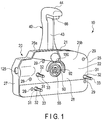
- FIG. 1 illustrates the side-mount type engine control apparatus 10.
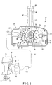
- FIG. 2 illustrates the interior of the engine control apparatus 10, and an example of an outboard motor 12 mounted in the rear of a hull 11.
- the outboard motor 12 includes a propeller 14, a shift mechanism 15, a shift actuator 16, a throttle mechanism 17, a throttle actuator 18, etc.
- the propeller 14 rotates with an engine (an internal-combustion engine) 13 used as a source of power.
- FIG. 3 is a vertical sectional view of a part of the engine control apparatus 10.
- a mount 19 is provided on the hull.
- the engine control apparatus 10 is mounted on a port-side mounting surface 19a of the mount 19.
- the mount 19 is provided near a cockpit of the hull.
- the engine control apparatus 10 includes an apparatus body 20, and a control lever 40.
- the control lever 40 can be mounted on either side of the two side surfaces (i.e., a first side surface 21 and a second side surface 22) of the apparatus body 20.
- the first side surface 21 and the second side surface 22 are located on sides opposite to each other with respect to a thickness direction of the apparatus body 20.
- the control lever 40 of the engine control apparatus 10 shown in FIG. 3 is mounted along the first side surface 21 of the apparatus body 20.
- the apparatus body 20 includes a housing 25 and a mechanism part 26.
- the housing 25 is made of rust-resistant metal such as an aluminum alloy.
- the mechanism part 26 is accommodated inside the housing 25.
- the housing 25 is comprised of a first housing element 27 and a second housing element 28.
- the first housing element 27 includes a first side wall 25a.
- the second housing element 28 includes a second side wall 25b.
- the first housing element 27 and the second housing element 28 are connected to each other by a screw member 29 ( FIG. 1 ).
- first side wall 25a and the second side wall 25b of the housing 25 are substantially parallel to each other.
- Each of the first side wall 25a and the second side wall 25b extends vertically along the mounting surface 19a of the mount 19.
- a thickness T1 of the housing 25 is less than a height H1 of the housing 25.
- a fixing portion 31 (see, for example, FIGS. 1 and 2 ) is formed at a plurality of places (for example, three places) of the housing 25.
- the number of fixing portions 31 may be other than three.
- the fixing portion 31 extends in a thickness direction (horizontal direction) of the housing 25 between the first side wall 25a and the second side wall 25b of the housing 25.
- a through-hole 32 is formed in each of the fixing portions 31 .
- Each of the through-holes 32 is communicated with the first side wall 25a and the second side wall 25b in the thickness direction of the housing 25.
- a screw member 33 for fixing the apparatus body 20 on the mount 19 is inserted.
- the control lever 40 includes a lever body 41, a cover member 42 made of resin, and a lock member 43.
- the lever body 41 is made of rust-resistant metal such as an aluminum alloy.
- the cover member 42 is mounted on the lever body 41.
- the lock member 43 is movable up and down.
- a handle portion 44 having such a shape that can be gripped by a boat operator by hand is provided.
- the cover member 42 is mounted on a first surface 41a of the lever body 41.
- a boss portion 50 is formed on a lower end side of the lever body 41 .
- a first fitting portion 51 and a second fitting portion 52 which are bilaterally symmetric with respect to each other, are formed.
- the first fitting portion 51 and the second fitting portion 52 face sides opposite to each other.
- a female thread portion 53 is formed at the center of the boss portion 50.
- a center bolt 55 is screwed into the female thread portion 53.
- the control lever 40 is fixed to an axis unit 70 by the center bolt 55.
- the joint member 60 includes a coupling portion 61 and a rotation prevention coupling portion 62.
- the coupling portion 61 has such a shape that it can be fitted to either of the first fitting portion 51 and the second fitting portion 52.
- the rotation prevention coupling portion 62 is shaped in a form other than circular, that is, shaped to be substantially rectangular, for example, as seen from a side surface of the control lever 40.
- FIG. 3 illustrates the state in which the coupling portion 61 is fitted to the first fitting portion 51.
- the lock member 43 provided on the control lever 40 is urged downward by a spring.
- a lower end 43a of the lock member 43 can be fitted to a first receiving portion 65 when the control lever 40 is at a neutral position (neutral).
- the first receiving portion 65 is formed on the first side wall 25a of the housing 25.
- an operation portion 66 for unlocking is provided at an upper end of the lock member 43. When this operation portion 66 is pulled up by a finger, the lower end 43a of the lock member 43 can be disengaged from the first receiving portion 65.
- FIG. 4 is a perspective view showing the interior of the apparatus body 20.
- the mechanism part 26 includes the axis unit 70, a driven gear 72, a detent mechanism 73 ( FIG. 2 ), and a friction mechanism 74 ( FIG. 5 ).
- the axis unit 70 includes a drive gear 71.
- the driven gear 72 meshes with the drive gear 71.
- the friction mechanism 74 applies friction to the axis unit 70.
- the drive gear 71 rotates together with the axis unit 70.
- the axis unit 70 is rotatably supported by bearings 75 and 76 ( FIG. 3 ). That is, the axis unit 70 is rotated about axis X1 ( FIG. 3 ) extending horizontally with respect to the housing 25. Accordingly, the control lever 40 can be rotated about axis X1 of the axis unit 70.
- Each of the drive gear 71 and the driven gear 72 is composed of a spur gear. These gears 71 and 72 are arranged parallel to the first side wall 25a and the second side wall 25b of the housing 25.
- the drive gear 71 and the driven gear 72 are sector gears partially having teeth formed thereon, and mesh with each other in an angular range in which the control lever 40 is rotated.
- marks 78 and 79 are shown on the drive gear 71 and the driven gear 72. The marks 78 and 79 are matched with each other when the control lever 40 is at the neutral position.
- a plurality of fixing portions 31 are provided on the housing 25. These fixing portions 31 are formed at positions (dead space) where they do not interfere with a movable member (a rotating body) in the internal space 30 of the housing 25.
- the movable members intended in this specification are, for example, the axis unit 70, the drive gear 71, and the driven gear 72. In other words, these fixing portions 31 are arranged by using the dead space occupying part of the internal space 30 of the housing 25.
- the detent mechanism 73 includes a detent plate 80, a holding member 81, and a spring 82.
- the detent plate 80 is provided on the axis unit 70.
- the holding member 81 is composed of a roller or a ball.
- the spring 82 urges the holding member 81 toward a peripheral surface of the detent plate 80.
- a neutral recess 85, a forward recess 86, and a reverse recess 87 are formed on the peripheral surface of the detent plate 80.
- a first lever mounting portion 91 is provided on one of end portions (i.e., the end portion on the left side in FIG. 3 ) of the axis unit 70.
- the first lever mounting portion 91 includes a first recess 90.
- the first recess 90 has such a shape that the rotation prevention coupling portion 62 of the joint member 60 can be fitted.
- the first recess 90 has a size which allows a head 55a of the center bolt 55 to be inserted therein.
- a second lever mounting portion 93 On the other end portion (i.e., the end portion on the right side in FIG. 3 ) of the axis unit 70, a second lever mounting portion 93 is provided.
- the second lever mounting portion 93 includes a second recess 92.
- the second recess 92 has such a shape that the rotation prevention coupling portion 62 of the joint member 60 can be fitted.
- the second recess 92 has a size which allows the head 55a of the center bolt 55 to be inserted therein.
- a sensor mounting plate 100 is provided on the first housing element 27.
- the sensor mounting plate 100 is arranged between the first side wall 25a and the second side wall 25b of the housing 25.
- the sensor mounting plate 100 is fixed to the first housing element 27 by a screw member 101.
- the sensor mounting plate 100 and the first side wall 25a are substantially parallel to each other.
- an angle sensor 110 is arranged on the sensor mounting plate 100.
- the angle sensor 110 outputs an electrical signal according to a rotational position of the driven gear 72.
- the driven gear 72 meshes with the drive gear 71. Accordingly, the position (operating angle) of the control lever 40 is detected by the angle sensor 110.
- a portion to be detected (for example, a magnet) of the angle sensor 110 is arranged on the driven gear 72.
- a wiring member (a harness) 111 is connected to the angle sensor 110.
- the wiring member 111 passes through the internal space 30 of the housing 25, and extends outside the housing 25 from a harness insertion hole 125.
- the wiring member 111 is connected to a control unit 130.
- the control unit 130 includes a control circuit such as a microcomputer.
- the control unit 130 controls the shift actuator 16 and the throttle actuator 18 in accordance with an electrical signal output from the angle sensor 110.
- the shift actuator 16 operates the shift mechanism 15 by way of a force transmission member such as a push-pull cable and a link member.
- the throttle actuator 18 operates the throttle mechanism 17 by way of a force transmission member such as a push-pull cable and a link member.
- the friction mechanism 74 includes band-shaped brake members 140 and 141, and an adjustment portion 142.
- the brake members 140 and 141 are in contact with a peripheral surface 70a of the axis unit 70.
- the adjustment portion 142 adjusts frictional force of the brake members 140 and 141.
- the adjustment portion 142 includes an adjustment screw 143.
- the adjustment screw 143 adjusts a pressure force of the brake members 140 and 141 on the peripheral surface 70a of the axis unit 70.
- An operation portion 144 of the adjustment screw 143 is disposed outside the housing 25. By rotating the adjustment screw 143 by the operation portion 144, the frictional force of the brake members 140 and 141 can be adjusted.
- FIG. 3 shows the state in which the apparatus body 20 is fixed to the port-side mounting surface 19a of the mount 19.
- the control lever 40 is fixed to the first lever mounting portion 91 by the center bolt 55 so as to be along the first side surface 21 of the apparatus body 20. More specifically, the coupling portion 61 of the joint member 60 is fitted to the first fitting portion 51 of the control lever 40. Further, the rotation prevention coupling portion 62 of the joint member 60 is fitted into the first recess 90 of the axis unit 70.
- the boss portion 50 of the control lever 40 is fixed to the first lever mounting portion 91 by the center bolt 55.
- the joint member 60 is sandwiched between the boss portion 50 and the first lever mounting portion 91.
- the head 55a of the center bolt 55 is accommodated in the second recess 92.
- control lever 40 can be rotated within a throttle operation range S1 through the forward-side shift position F.
- the neutral position (neutral) N serves as a boundary point.
- control lever 40 can be rotated within a throttle operation range S2 through the reverse-side shift position R.
- the engine control apparatus 10 is desired to be arranged on a starboard-side mounting surface 19b ( FIG. 9 ) of the mount 19.
- FIG. 7 shows the state in which the control lever 40 is removed from the apparatus body 20.
- the removed control lever 40 is arranged along the second side surface 22 of the apparatus body 20 as shown in FIG. 8 .
- FIG. 9 shows the state in which the engine control apparatus 10 is mounted on the starboard-side mounting surface 19b.
- the coupling portion 61 of the joint member 60 is fitted to the second fitting portion 52 of the boss portion 50 of the control lever 40.
- the rotation prevention coupling portion 62 of the joint member 60 is fitted into the second recess 92 of the axis unit 70.
- the boss portion 50 of the control lever 40 is fixed to the second lever mounting portion 93 by the center bolt 55.
- the joint member 60 is sandwiched between the boss portion 50 and the second lever mounting portion 93.
- the head 55a of the center bolt 55 is accommodated in the first recess 90.
- the cover member 42 is mounted on a second surface 41b (i.e., a surface on the opposite side of the first surface 41a) of the lever body 41.
- the lock member 43 is provided on the control lever 40.
- the lower end 43a of the lock member 43 can be fitted to a second receiving portion 150 when the control lever 40 is at the neutral position (neutral).
- the second receiving portion 150 is formed on the second side wall 25b of the housing 25.
- the engine control apparatus 10 of the present embodiment includes the control unit 130.
- the operating angle of the control lever 40 is input to the control unit 130 via the angle sensor 110 and the wiring member 111. Consequently, the shift mechanism 15 and the throttle mechanism 17 can be actuated by an electrical signal. Accordingly, in the engine control apparatus 10 of the present embodiment, there is no need to arrange a mechanical push-pull cable for force transmission inside the housing 25.
- the drive gear 71 and the driven gear 72 are arranged parallel to the first side wall 25a and the second side wall 25b in space between the first side wall 25a and the second side wall 25b of the housing 25.
- the angle sensor 110 is arranged between the second side wall 25b and the sensor mounting plate 100. Accordingly, the thickness T1 ( FIG. 3 ) of the housing 25 can be made smaller than that of a conventional engine control apparatus, and the housing 25 can be made slim (compact).
- a movable member whose movable range is large such as a shift movable arm and a throttle movable arm inside the housing 25.
- a plurality of fixing portions 31 can be arranged in the internal space (dead space) 30 of the housing 25.
- positions where the fixing portions 31 are to be provided and the shape of the housing 25 can be determined with more freedom, and the housing 25 can be structured to be compact.
- the fixing portion 31 extends in a thickness direction (a horizontal direction) of the housing 25. Further, in the fixing portion 31, the through-hole 32 which is communicated with the first side wall 25a and the second side wall 25b of the housing 25 is formed. By the screw member 33 inserted into this through-hole 32, the apparatus body 20 can be arranged on either the port-side mounting surface 19a or the starboard-side mounting surface 19b.
- a portion to be detected for example, a magnet
- the portion to be detected does not need to be provided on the axis unit 70.
- the first lever mounting portion 91 and the second lever mounting portion 93 can be formed on the axis unit 70.
- the control lever 40 can be disposed on either side of the first side surface 21 and the second side surface 22 of the apparatus body 20. Consequently, the engine control apparatus 10 can be mounted on either of the port-side mounting surface and the starboard-side mounting surface.
- the brake members 140 and 141 are made to contact the peripheral surface 70a of the axis unit 70.
- the engine control apparatus 10 of the present embodiment has been devised to make the frictional force of the brake members 140 and 141 adjustable by the adjustment screw 143. By this feature, not only can a moderate degree of frictional force be applied to the control lever 40, but movement of the control lever 40 by vibration, etc., can also be prevented.
- the engine control apparatus 10 of the present embodiment can be used for an electrically-powered boat which rotates a propeller by an electric motor. Since the electric motor does not require a shift mechanism, it suffices that a forward-side accelerator control range and a reverse-side accelerator control range be set in the control lever. Accordingly, in a detent plate of the detent mechanism of the electrically-powered boat, it is necessary to provide only the neutral recess 85.
Landscapes
- Engineering & Computer Science (AREA)
- Mechanical Engineering (AREA)
- Physics & Mathematics (AREA)
- General Physics & Mathematics (AREA)
- Automation & Control Theory (AREA)
- General Engineering & Computer Science (AREA)
- Chemical & Material Sciences (AREA)
- Combustion & Propulsion (AREA)
- Ocean & Marine Engineering (AREA)
- Control Of Throttle Valves Provided In The Intake System Or In The Exhaust System (AREA)
- Mechanical Control Devices (AREA)
Abstract
Description
- The present invention relates to a side-mount type engine control apparatus for performing a throttle operation, etc., of an engine of a boat, for example.
- In an engine system for a boat including an engine (an internal-combustion engine) as a power source, an engine control apparatus which performs a shift operation and a throttle operation by a control lever is known. In
JPH4-193696 A JP 2015-166225 A JP 2015-032226 A - The engine control apparatus includes a control lever. When the control lever is moved to a forward-side shift position or a reverse-side shift position from a neutral position, a mechanical transmission cable for shift is moved to a shift position on the forward side or the reverse side. When the control lever is further rotated, the control lever enters a throttle operation range. In the throttle operation range, as a mechanical transmission cable for throttle is moved in accordance with an operating angle of the control lever, throttle control is performed. In other words, a movement of the control lever is transmitted to the engine via the mechanical transmission cables.
- A top-mount type engine control apparatus can be used in a medium-sized or large-sized boat having a relatively large cockpit and a dedicated mount without problems. However, a top-mount type engine control apparatus may not be used in a small boat in which the size of the mount is limited. In contrast, the side-mount type engine control apparatus has a structure in which the housing is fixed to a side surface of the mount. Accordingly, the side-mount type engine control apparatus has an advantage that it can be easily mounted on a relatively small boat. However, in a case of a boat in which a high-power engine is mounted on a small hull, the side-mount type engine control apparatus is required to operate mechanical transmission cables with great force. Accordingly, shifting or throttle operability is deteriorated.
- In an engine control apparatus which uses the mechanical transmission cables, a part of the transmission cables, and movable members such as a shift arm and a throttle arm are arranged inside the housing. A movable range of these movable members is relatively large. The engine control apparatus is fixed to the mounting surface of the hull by a bolt. This bolt penetrates the housing. Accordingly, it is difficult to arrange the bolt in the housing such that it does not interfere with the movable members. Moreover, the housing must have high rigidity so that it can withstand a reaction force produced when the movable members move. Thus, one idea was to form a fixing portion such as a flange near an outer periphery of the housing, and fix this fixing portion to the mount by a bolt. However, a problem in the above is that the shape of the housing having the flange is restricted, and moreover, a contour of the housing is enlarged.
- An object of the present invention is to provide a side-mount type engine control which can easily operate a control lever, and includes a housing which is structured to be slim and compact.
- A side-mount type engine control apparatus of one embodiment comprises a housing, an axis unit, a control lever, a drive gear, a driven gear, a sensor mounting plate, an angle sensor, and a fixing portion formed on the housing. The axis unit is provided rotatably in the housing. The control lever is mounted on the axis unit, and is rotated to a forward side or a reverse side from a neutral position. The drive gear is rotated together with the axis unit. The driven gear meshes with the drive gear. The sensor mounting plate is arranged between a first side wall and a second side wall of the housing. The angle sensor is arranged on the sensor mounting plate. The fixing portion includes a through-hole. This through-hole is communicated with the first side wall and the second side wall of the housing. In the through-hole, a screw member is inserted. By this screw member, the housing is fixed to a mounting surface.
- According to this embodiment, it is possible to provide a side-mount type engine control apparatus which is capable of performing a throttle operation, etc., of the control lever with relatively small force, has good operability, and is configured to be slim and compact. Moreover, the engine control apparatus of the present embodiment can be mounted on a port-side mounting surface or a starboard-side mounting surface of a mount provided on a hull.
- In a preferred embodiment, a friction mechanism which applies friction to the axis unit is provided. The friction mechanism comprises a brake member, an adjustment screw, and an operation portion. The brake member is in contact with a peripheral surface of the axis unit. The adjustment screw adjusts a pressure force of the brake member on the peripheral surface of the axis unit. The operation portion rotates the adjustment screw.
- An example of the control lever includes a lever body fixed to the axis unit, and a cover member arranged on the lever body. The cover member is attachable to either of a first surface of the lever body and a second surface on an opposite side of the first surface.
- Further, one embodiment comprises a detent plate provided on the axis unit, a holding member such as a ball or a roller, and a spring. The holding member is engageable with a recess formed on a peripheral surface of the detent plate. The spring urges the holding member toward the peripheral surface of the detent plate.
- According to one embodiment, a first fitting portion, a second fitting portion, a first lever mounting portion, a second lever mounting portion, a joint member, and a center bolt are provided. The first fitting portion is formed on a boss portion on a lower end side of the control lever. The second fitting portion is provided on a side opposite to the first fitting portion of the boss portion. The first lever mounting portion includes a first recess formed on one end portion of the axis unit. The second lever mounting portion includes a second recess formed on the other end portion of the axis unit. The joint member includes a coupling portion fitted to one of the first fitting portion and the second fitting portion. Further, the joint member includes a rotation prevention coupling portion fitted into one of the first recess and the second recess. The center bolt fixes the boss portion and the joint member to the axis unit. In this embodiment, a head of the center bolt may be accommodated in the first recess or the second recess of the axis unit.
- The invention can be more fully understood from the following detailed description when taken in conjunction with the accompanying drawings, in which:
-
FIG. 1 is a perspective view of a side-mount type engine control apparatus according to one embodiment, and a control lever is provided along a first side surface of an apparatus body. -
FIG. 2 is a side view showing the interior of the engine control apparatus, and an outboard motor. -
FIG. 3 is a vertical sectional view of a part of the engine control apparatus. -
FIG. 4 is a perspective view showing the interior of the apparatus body of the engine control apparatus. -
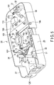
FIG. 5 is a perspective view showing a friction mechanism of the engine control apparatus. -
FIG. 6 is a side view of the control lever of the engine control apparatus being operated. -
FIG. 7 is a vertical sectional view of the control lever in a state in which it is removed from the apparatus body of the engine control apparatus. -
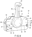
FIG. 8 is a perspective view of the control lever of the engine control apparatus being provided along a second side surface of the apparatus body. -
FIG. 9 is a vertical sectional view of the engine control apparatus shown inFIG. 8 . - A side-mount type
engine control apparatus 10 according to one embodiment will be described with reference toFIGS. 1 to 9 . -
FIG. 1 illustrates the side-mount typeengine control apparatus 10.FIG. 2 illustrates the interior of theengine control apparatus 10, and an example of anoutboard motor 12 mounted in the rear of ahull 11. Theoutboard motor 12 includes apropeller 14, ashift mechanism 15, ashift actuator 16, athrottle mechanism 17, athrottle actuator 18, etc. Thepropeller 14 rotates with an engine (an internal-combustion engine) 13 used as a source of power. -
FIG. 3 is a vertical sectional view of a part of theengine control apparatus 10. Amount 19 is provided on the hull. Theengine control apparatus 10 is mounted on a port-side mounting surface 19a of themount 19. Themount 19 is provided near a cockpit of the hull. Theengine control apparatus 10 includes anapparatus body 20, and acontrol lever 40. Thecontrol lever 40 can be mounted on either side of the two side surfaces (i.e., afirst side surface 21 and a second side surface 22) of theapparatus body 20. Thefirst side surface 21 and thesecond side surface 22 are located on sides opposite to each other with respect to a thickness direction of theapparatus body 20. Thecontrol lever 40 of theengine control apparatus 10 shown inFIG. 3 is mounted along thefirst side surface 21 of theapparatus body 20. - The
apparatus body 20 includes ahousing 25 and amechanism part 26. Thehousing 25 is made of rust-resistant metal such as an aluminum alloy. Themechanism part 26 is accommodated inside thehousing 25. Thehousing 25 is comprised of afirst housing element 27 and asecond housing element 28. Thefirst housing element 27 includes afirst side wall 25a. Thesecond housing element 28 includes asecond side wall 25b. Thefirst housing element 27 and thesecond housing element 28 are connected to each other by a screw member 29 (FIG. 1 ). - As shown in
FIG. 3 , thefirst side wall 25a and thesecond side wall 25b of thehousing 25 are substantially parallel to each other. Each of thefirst side wall 25a and thesecond side wall 25b extends vertically along the mountingsurface 19a of themount 19. A thickness T1 of thehousing 25 is less than a height H1 of thehousing 25. Inside thehousing 25, aninternal space 30 for accommodating themechanism part 26 is formed. Themechanism part 26 will be described in detail later. - In order to fix the
apparatus body 20 on themount 19, a fixing portion 31 (see, for example,FIGS. 1 and2 ) is formed at a plurality of places (for example, three places) of thehousing 25. The number of fixingportions 31 may be other than three. The fixingportion 31 extends in a thickness direction (horizontal direction) of thehousing 25 between thefirst side wall 25a and thesecond side wall 25b of thehousing 25. In each of the fixingportions 31, a through-hole 32 is formed. Each of the through-holes 32 is communicated with thefirst side wall 25a and thesecond side wall 25b in the thickness direction of thehousing 25. In the through-hole 32, ascrew member 33 for fixing theapparatus body 20 on themount 19 is inserted. - The
control lever 40 includes alever body 41, acover member 42 made of resin, and alock member 43. Thelever body 41 is made of rust-resistant metal such as an aluminum alloy. Thecover member 42 is mounted on thelever body 41. Thelock member 43 is movable up and down. On an upper end of thecontrol lever 40, ahandle portion 44 having such a shape that can be gripped by a boat operator by hand is provided. Thecover member 42 is mounted on afirst surface 41a of thelever body 41. - As shown in
FIG. 3 , on a lower end side of thelever body 41, aboss portion 50 is formed. On theboss portion 50, a firstfitting portion 51 and a secondfitting portion 52, which are bilaterally symmetric with respect to each other, are formed. The firstfitting portion 51 and the secondfitting portion 52 face sides opposite to each other. At the center of theboss portion 50, afemale thread portion 53 is formed. Acenter bolt 55 is screwed into thefemale thread portion 53. Thecontrol lever 40 is fixed to anaxis unit 70 by thecenter bolt 55. - On the
boss portion 50 of thecontrol lever 40, ajoint member 60 is provided. Thejoint member 60 includes acoupling portion 61 and a rotationprevention coupling portion 62. Thecoupling portion 61 has such a shape that it can be fitted to either of the firstfitting portion 51 and the secondfitting portion 52. The rotationprevention coupling portion 62 is shaped in a form other than circular, that is, shaped to be substantially rectangular, for example, as seen from a side surface of thecontrol lever 40.FIG. 3 illustrates the state in which thecoupling portion 61 is fitted to the firstfitting portion 51. - The
lock member 43 provided on thecontrol lever 40 is urged downward by a spring. Alower end 43a of thelock member 43 can be fitted to a first receivingportion 65 when thecontrol lever 40 is at a neutral position (neutral). The first receivingportion 65 is formed on thefirst side wall 25a of thehousing 25. At an upper end of thelock member 43, anoperation portion 66 for unlocking is provided. When thisoperation portion 66 is pulled up by a finger, thelower end 43a of thelock member 43 can be disengaged from the first receivingportion 65. -
FIG. 4 is a perspective view showing the interior of theapparatus body 20. In theinternal space 30 of thehousing 25, themechanism part 26 is arranged. Themechanism part 26 includes theaxis unit 70, a drivengear 72, a detent mechanism 73 (FIG. 2 ), and a friction mechanism 74 (FIG. 5 ). Theaxis unit 70 includes adrive gear 71. The drivengear 72 meshes with thedrive gear 71. Thefriction mechanism 74 applies friction to theaxis unit 70. Thedrive gear 71 rotates together with theaxis unit 70. Theaxis unit 70 is rotatably supported bybearings 75 and 76 (FIG. 3 ). That is, theaxis unit 70 is rotated about axis X1 (FIG. 3 ) extending horizontally with respect to thehousing 25. Accordingly, thecontrol lever 40 can be rotated about axis X1 of theaxis unit 70. - Each of the
drive gear 71 and the drivengear 72 is composed of a spur gear. These gears 71 and 72 are arranged parallel to thefirst side wall 25a and thesecond side wall 25b of thehousing 25. Thedrive gear 71 and the drivengear 72 are sector gears partially having teeth formed thereon, and mesh with each other in an angular range in which thecontrol lever 40 is rotated. On thedrive gear 71 and the drivengear 72, marks 78 and 79 (FIG. 2 ) are shown. Themarks control lever 40 is at the neutral position. - A plurality of fixing
portions 31 are provided on thehousing 25. These fixingportions 31 are formed at positions (dead space) where they do not interfere with a movable member (a rotating body) in theinternal space 30 of thehousing 25. The movable members intended in this specification are, for example, theaxis unit 70, thedrive gear 71, and the drivengear 72. In other words, these fixingportions 31 are arranged by using the dead space occupying part of theinternal space 30 of thehousing 25. - As shown in
FIG. 2 , thedetent mechanism 73 includes adetent plate 80, a holdingmember 81, and aspring 82. Thedetent plate 80 is provided on theaxis unit 70. The holdingmember 81 is composed of a roller or a ball. Thespring 82 urges the holdingmember 81 toward a peripheral surface of thedetent plate 80. On the peripheral surface of thedetent plate 80, aneutral recess 85, aforward recess 86, and areverse recess 87 are formed. - When the
control lever 40 is at a neutral position N, the holdingmember 81 falls into theneutral recess 85. In this way, thecontrol lever 40 is kept in the neutral position N. When thecontrol lever 40 is moved to a forward-side shift position F (FIG. 6 ), the holdingmember 81 falls into theforward recess 86. In this way, thecontrol lever 40 is kept in the forward-side shift position F. When thecontrol lever 40 is moved to a reverse-side shift position R, the holdingmember 81 falls into thereverse recess 87. In this way, thecontrol lever 40 is kept in the reverse-side shift position R. - As shown in
FIG. 3 , on one of end portions (i.e., the end portion on the left side inFIG. 3 ) of theaxis unit 70, a firstlever mounting portion 91 is provided. The firstlever mounting portion 91 includes afirst recess 90. Thefirst recess 90 has such a shape that the rotationprevention coupling portion 62 of thejoint member 60 can be fitted. Also, thefirst recess 90 has a size which allows ahead 55a of thecenter bolt 55 to be inserted therein. - On the other end portion (i.e., the end portion on the right side in
FIG. 3 ) of theaxis unit 70, a secondlever mounting portion 93 is provided. The secondlever mounting portion 93 includes asecond recess 92. Thesecond recess 92 has such a shape that the rotationprevention coupling portion 62 of thejoint member 60 can be fitted. Also, thesecond recess 92 has a size which allows thehead 55a of thecenter bolt 55 to be inserted therein. - A
sensor mounting plate 100 is provided on thefirst housing element 27. Thesensor mounting plate 100 is arranged between thefirst side wall 25a and thesecond side wall 25b of thehousing 25. Thesensor mounting plate 100 is fixed to thefirst housing element 27 by ascrew member 101. Thesensor mounting plate 100 and thefirst side wall 25a are substantially parallel to each other. On thesensor mounting plate 100, anangle sensor 110 is arranged. Theangle sensor 110 outputs an electrical signal according to a rotational position of the drivengear 72. The drivengear 72 meshes with thedrive gear 71. Accordingly, the position (operating angle) of thecontrol lever 40 is detected by theangle sensor 110. A portion to be detected (for example, a magnet) of theangle sensor 110 is arranged on the drivengear 72. - As shown in
FIG. 2 , a wiring member (a harness) 111 is connected to theangle sensor 110. Thewiring member 111 passes through theinternal space 30 of thehousing 25, and extends outside thehousing 25 from aharness insertion hole 125. Thewiring member 111 is connected to acontrol unit 130. Thecontrol unit 130 includes a control circuit such as a microcomputer. Thecontrol unit 130 controls theshift actuator 16 and thethrottle actuator 18 in accordance with an electrical signal output from theangle sensor 110. Theshift actuator 16 operates theshift mechanism 15 by way of a force transmission member such as a push-pull cable and a link member. Thethrottle actuator 18 operates thethrottle mechanism 17 by way of a force transmission member such as a push-pull cable and a link member. - As shown in
FIG. 5 , thefriction mechanism 74 includes band-shapedbrake members adjustment portion 142. Thebrake members peripheral surface 70a of theaxis unit 70. Theadjustment portion 142 adjusts frictional force of thebrake members adjustment portion 142 includes anadjustment screw 143. Theadjustment screw 143 adjusts a pressure force of thebrake members peripheral surface 70a of theaxis unit 70. Anoperation portion 144 of theadjustment screw 143 is disposed outside thehousing 25. By rotating theadjustment screw 143 by theoperation portion 144, the frictional force of thebrake members -
FIG. 3 shows the state in which theapparatus body 20 is fixed to the port-side mounting surface 19a of themount 19. Thecontrol lever 40 is fixed to the firstlever mounting portion 91 by thecenter bolt 55 so as to be along thefirst side surface 21 of theapparatus body 20. More specifically, thecoupling portion 61 of thejoint member 60 is fitted to the firstfitting portion 51 of thecontrol lever 40. Further, the rotationprevention coupling portion 62 of thejoint member 60 is fitted into thefirst recess 90 of theaxis unit 70. In this state, theboss portion 50 of thecontrol lever 40 is fixed to the firstlever mounting portion 91 by thecenter bolt 55. Thejoint member 60 is sandwiched between theboss portion 50 and the firstlever mounting portion 91. Thehead 55a of thecenter bolt 55 is accommodated in thesecond recess 92. - An action of
engine control apparatus 10 of the present embodiment will be described below. - As shown in
FIG. 6 , thecontrol lever 40 can be rotated within a throttle operation range S1 through the forward-side shift position F. The neutral position (neutral) N serves as a boundary point. Also, thecontrol lever 40 can be rotated within a throttle operation range S2 through the reverse-side shift position R. - When the
control lever 40 is moved to the forward-side shift position F from the neutral position N, theaxis unit 70 is rotated in a first direction. Consequently, thedrive gear 71 and the drivengear 72 are rotated. Thus, an electrical signal indicating that thecontrol lever 40 has moved to the forward-side shift position F is output to the control unit 130 (FIG. 2 ) from theangle sensor 110. Theshift actuator 16 is thereby switched from neutral to a forward-side shift position. - When the
control lever 40 is moved to be in the throttle operation range S1 from the forward-side shift position F, thedrive gear 71 and the drivengear 72 are further rotated in accordance with an angle of thecontrol lever 40. Accordingly, an electrical signal according to the angle of thecontrol lever 40 is output to thecontrol unit 130 from theangle sensor 110. In this way, thethrottle actuator 18 is controlled, and thepropeller 14 is rotated at a rotation speed according to a throttle opening. - When the
control lever 40 is moved to the reverse-side shift position R from the neutral position N, theaxis unit 70 is rotated in a second direction. Consequently, thedrive gear 71 and the drivengear 72 are rotated. Thus, an electrical signal indicating that thecontrol lever 40 has moved to the reverse-side shift position R is output to thecontrol unit 130 from theangle sensor 110. Theshift actuator 16 is thereby switched from neutral to a reverse-side shift position. - When the
control lever 40 is moved to be in the throttle operation range S2 from the reverse-side shift position R, thedrive gear 71 and the drivengear 72 are further rotated in accordance with an angle of thecontrol lever 40. Accordingly, an electrical signal according to the angle of thecontrol lever 40 is output to thecontrol unit 130 from theangle sensor 110. In this way, thethrottle actuator 18 is controlled, and thepropeller 14 is rotated at a rotation speed according to the throttle opening. - Depending on a boat, the
engine control apparatus 10 is desired to be arranged on a starboard-side mounting surface 19b (FIG. 9 ) of themount 19. In such a case, by removing thecenter bolt 55 from theboss portion 50 of thecontrol lever 40, thecontrol lever 40 is removed from theapparatus body 20.FIG. 7 shows the state in which thecontrol lever 40 is removed from theapparatus body 20. The removedcontrol lever 40 is arranged along thesecond side surface 22 of theapparatus body 20 as shown inFIG. 8 . -
FIG. 9 shows the state in which theengine control apparatus 10 is mounted on the starboard-side mounting surface 19b. In this case, thecoupling portion 61 of thejoint member 60 is fitted to the secondfitting portion 52 of theboss portion 50 of thecontrol lever 40. Further, the rotationprevention coupling portion 62 of thejoint member 60 is fitted into thesecond recess 92 of theaxis unit 70. Theboss portion 50 of thecontrol lever 40 is fixed to the secondlever mounting portion 93 by thecenter bolt 55. Thejoint member 60 is sandwiched between theboss portion 50 and the secondlever mounting portion 93. Thehead 55a of thecenter bolt 55 is accommodated in thefirst recess 90. Thecover member 42 is mounted on asecond surface 41b (i.e., a surface on the opposite side of thefirst surface 41a) of thelever body 41. - The
lock member 43 is provided on thecontrol lever 40. Thelower end 43a of thelock member 43 can be fitted to asecond receiving portion 150 when thecontrol lever 40 is at the neutral position (neutral). Thesecond receiving portion 150 is formed on thesecond side wall 25b of thehousing 25. When theoperation portion 66 for unlocking is pulled up by a finger, thelower end 43a of thelock member 43 is disengaged from thesecond receiving portion 150. - The
engine control apparatus 10 of the present embodiment includes thecontrol unit 130. The operating angle of thecontrol lever 40 is input to thecontrol unit 130 via theangle sensor 110 and thewiring member 111. Consequently, theshift mechanism 15 and thethrottle mechanism 17 can be actuated by an electrical signal. Accordingly, in theengine control apparatus 10 of the present embodiment, there is no need to arrange a mechanical push-pull cable for force transmission inside thehousing 25. - Moreover, the
drive gear 71 and the drivengear 72 are arranged parallel to thefirst side wall 25a and thesecond side wall 25b in space between thefirst side wall 25a and thesecond side wall 25b of thehousing 25. Theangle sensor 110 is arranged between thesecond side wall 25b and thesensor mounting plate 100. Accordingly, the thickness T1 (FIG. 3 ) of thehousing 25 can be made smaller than that of a conventional engine control apparatus, and thehousing 25 can be made slim (compact). - Also, in the
engine control apparatus 10 of the present embodiment, there is no need to arrange a movable member whose movable range is large such as a shift movable arm and a throttle movable arm inside thehousing 25. Accordingly, a plurality of fixingportions 31 can be arranged in the internal space (dead space) 30 of thehousing 25. Thus, positions where the fixingportions 31 are to be provided and the shape of thehousing 25 can be determined with more freedom, and thehousing 25 can be structured to be compact. By these fixingportions 31, theapparatus body 20 is fixed to themount 19. - Further, in the side-mount type
engine control apparatus 10 according to the present embodiment, the fixingportion 31 extends in a thickness direction (a horizontal direction) of thehousing 25. Further, in the fixingportion 31, the through-hole 32 which is communicated with thefirst side wall 25a and thesecond side wall 25b of thehousing 25 is formed. By thescrew member 33 inserted into this through-hole 32, theapparatus body 20 can be arranged on either the port-side mounting surface 19a or the starboard-side mounting surface 19b. - In the
engine control apparatus 10 of the present embodiment, a portion to be detected (for example, a magnet) for theangle sensor 110 is provided on the drivengear 72. In other words, the portion to be detected does not need to be provided on theaxis unit 70. Accordingly, the firstlever mounting portion 91 and the secondlever mounting portion 93 can be formed on theaxis unit 70. By this feature, thecontrol lever 40 can be disposed on either side of thefirst side surface 21 and thesecond side surface 22 of theapparatus body 20. Consequently, theengine control apparatus 10 can be mounted on either of the port-side mounting surface and the starboard-side mounting surface. - Further, in the
engine control apparatus 10 of the present embodiment, thebrake members peripheral surface 70a of theaxis unit 70. Moreover, theengine control apparatus 10 of the present embodiment has been devised to make the frictional force of thebrake members adjustment screw 143. By this feature, not only can a moderate degree of frictional force be applied to thecontrol lever 40, but movement of thecontrol lever 40 by vibration, etc., can also be prevented. - Note that the
engine control apparatus 10 of the present embodiment can be used for an electrically-powered boat which rotates a propeller by an electric motor. Since the electric motor does not require a shift mechanism, it suffices that a forward-side accelerator control range and a reverse-side accelerator control range be set in the control lever. Accordingly, in a detent plate of the detent mechanism of the electrically-powered boat, it is necessary to provide only theneutral recess 85. - In carrying out the present invention, it is needless to say that the shape, structure, and arrangement of the respective members which constitute the side-mount type engine control apparatus, such as the housing, control lever, fixing portion, axis unit, drive gear, driven gear, and angle sensor, may be modified variously.
Claims (6)
- A side-mount type engine control apparatus characterized by comprising:a housing (25);an axis unit (70) provided rotatably in the housing (25);a control lever (40) which is mounted on the axis unit (70), and is rotated to a forward side or a reverse side from a neutral position;a drive gear (71) which rotates together with the axis unit (70);a driven gear (72) which meshes with the drive gear (71);a sensor mounting plate (100) arranged between a first side wall (25a) and a second side wall (25b) of the housing (25);an angle sensor (110) arranged on the sensor mounting plate (100); anda fixing portion (31) which is formed on the housing (25), and includes a through-hole (32) into which a screw member (33) for fixing the housing (25) to a mounting surface is inserted, the through-hole (32) being communicated with the first side wall (25a) and the second side wall (25b) of the housing (25).
- The engine control apparatus of Claim 1, characterized by further comprising a friction mechanism (74) which applies friction to the axis unit (70), wherein
the friction mechanism (74) comprises:brake members (140, 141) in contact with a peripheral surface of the axis unit (70);an adjustment screw (143) which adjusts a pressure force of the brake members (140, 141) on the peripheral surface of the axis unit (70); andan operation portion (144) which rotates the adjustment screw (143). - The engine control apparatus of Claim 1, characterized in that the control lever (40) includes a lever body (41) fixed to the axis unit (70), and a cover member (42) arranged on the lever body (41), and the cover member (42) is attachable to either of a first surface (41a) of the lever body (41) and a second surface (41b) on an opposite side of the first surface (41a).
- The engine control apparatus of Claim 1, characterized by further comprising:a detent plate (80) provided on the axis unit (70) ;a holding member (81) engageable with a recess (85, 86, 87) formed on a peripheral surface of the detent plate (80); anda spring (82) which urges the holding member (81) toward the peripheral surface of the detent plate (80).
- The engine control apparatus of Claim 1, characterized by further comprising:a first fitting portion (51) formed on a boss portion (50) on a lower end side of the control lever (40);a second fitting portion (52) provided on a side opposite to the first fitting portion (51) of the boss portion (50);a first lever mounting portion (91) including a first recess (90) formed on one end portion of the axis unit (70);a second lever mounting portion (93) including a second recess (92) formed on the other end portion of the axis unit (70);a joint member (60) including a coupling portion (61) fitted to one of the first fitting portion (51) and the second fitting portion (52), and a rotation prevention coupling portion (62) fitted into one of the first recess (90) and the second recess (92); anda center bolt (55) which fixes the boss portion (50) and the joint member (60) to the axis unit (70).
- The engine control apparatus of Claim 5, characterized in that a head (55a) of the center bolt (55) is accommodated in the first recess (90) or the second recess (92) of the axis unit (70).
Applications Claiming Priority (1)
| Application Number | Priority Date | Filing Date | Title |
|---|---|---|---|
| JP2017013161A JP6899545B2 (en) | 2017-01-27 | 2017-01-27 | Side mount type engine control device |
Publications (2)
| Publication Number | Publication Date |
|---|---|
| EP3354558A1 true EP3354558A1 (en) | 2018-08-01 |
| EP3354558B1 EP3354558B1 (en) | 2021-09-22 |
Family
ID=61017780
Family Applications (1)
| Application Number | Title | Priority Date | Filing Date |
|---|---|---|---|
| EP18152136.0A Active EP3354558B1 (en) | 2017-01-27 | 2018-01-17 | Side-mount type engine control apparatus |
Country Status (3)
| Country | Link |
|---|---|
| US (1) | US10252785B2 (en) |
| EP (1) | EP3354558B1 (en) |
| JP (1) | JP6899545B2 (en) |
Cited By (1)
| Publication number | Priority date | Publication date | Assignee | Title |
|---|---|---|---|---|
| CN112065977A (en) * | 2020-08-31 | 2020-12-11 | 安徽江淮汽车集团股份有限公司 | Gear shifting position identification method, gear shifting position identification device, gear shifting position identification equipment and storage medium |
Families Citing this family (8)
| Publication number | Priority date | Publication date | Assignee | Title |
|---|---|---|---|---|
| DE102016121747B4 (en) * | 2016-11-14 | 2021-09-16 | Torqeedo Gmbh | Device for specifying the speed level of an electric drive in a boat |
| US10864962B2 (en) * | 2018-06-06 | 2020-12-15 | Sensata Technologies, Inc. | Electronic throttle control assembly |
| USD890678S1 (en) * | 2019-01-17 | 2020-07-21 | Caterpillar Inc. | Lever head |
| USD890679S1 (en) * | 2019-01-17 | 2020-07-21 | Caterpillar Inc. | Lever head handles |
| US12122449B2 (en) | 2019-09-06 | 2024-10-22 | Sensata Technologies, Inc. | Steer by wire system with redundant angular position sensing and an end-of-travel stop |
| US11370483B2 (en) | 2020-01-27 | 2022-06-28 | Sensata Technologies, Inc. | Steer by wire system with dynamic braking and endstop cushioning for haptic feel |
| DE102020120323A1 (en) * | 2020-07-31 | 2022-02-03 | Torqeedo Gmbh | Device for setting the speed of a boat |
| CN114263537B (en) * | 2020-09-16 | 2023-10-17 | 广东逸动科技有限公司 | Marine electronic throttle control device, control method and ship |
Citations (7)
| Publication number | Priority date | Publication date | Assignee | Title |
|---|---|---|---|---|
| US4119186A (en) * | 1977-02-28 | 1978-10-10 | Outboard Marine Corporation | Single lever control having a throttle warm-up lever |
| JPS57153311A (en) * | 1981-03-17 | 1982-09-21 | Yamaha Motor Co Ltd | Remote control device |
| US4632232A (en) * | 1984-07-02 | 1986-12-30 | Outboard Marine Corporation | Single lever remote control-throttle dwell and friction mechanism |
| JPH04193696A (en) * | 1990-11-28 | 1992-07-13 | Asahi Denso Kk | Both rightward and leftward reversible operating lever |
| US20060046585A1 (en) * | 2004-08-25 | 2006-03-02 | Honda Motor Co., Ltd. | Remote operation system for outboard motor |
| JP2015032226A (en) | 2013-08-05 | 2015-02-16 | 日本発條株式会社 | Engine control device |
| JP2015166225A (en) | 2014-03-04 | 2015-09-24 | 日本発條株式会社 | Control lever and remote control device |
Family Cites Families (7)
| Publication number | Priority date | Publication date | Assignee | Title |
|---|---|---|---|---|
| JP2006062482A (en) * | 2004-08-25 | 2006-03-09 | Honda Motor Co Ltd | Remote control device for outboard motor |
| JP2006187096A (en) * | 2004-12-27 | 2006-07-13 | Nidec Sankyo Corp | Geared motor |
| JP2011107334A (en) * | 2009-11-16 | 2011-06-02 | Fujifilm Corp | Lens drive device |
| US20120077394A1 (en) * | 2010-09-27 | 2012-03-29 | Compx International Inc. | Electronic ski control |
| JP2013232999A (en) * | 2012-04-27 | 2013-11-14 | Nidec Sankyo Corp | Motor actuator |
| JP2014237399A (en) * | 2013-06-07 | 2014-12-18 | スズキ株式会社 | Remote control device |
| US10216216B2 (en) * | 2015-03-20 | 2019-02-26 | Omron Corporation | Lever unit |
-
2017
- 2017-01-27 JP JP2017013161A patent/JP6899545B2/en active Active
-
2018
- 2018-01-17 US US15/873,192 patent/US10252785B2/en active Active
- 2018-01-17 EP EP18152136.0A patent/EP3354558B1/en active Active
Patent Citations (7)
| Publication number | Priority date | Publication date | Assignee | Title |
|---|---|---|---|---|
| US4119186A (en) * | 1977-02-28 | 1978-10-10 | Outboard Marine Corporation | Single lever control having a throttle warm-up lever |
| JPS57153311A (en) * | 1981-03-17 | 1982-09-21 | Yamaha Motor Co Ltd | Remote control device |
| US4632232A (en) * | 1984-07-02 | 1986-12-30 | Outboard Marine Corporation | Single lever remote control-throttle dwell and friction mechanism |
| JPH04193696A (en) * | 1990-11-28 | 1992-07-13 | Asahi Denso Kk | Both rightward and leftward reversible operating lever |
| US20060046585A1 (en) * | 2004-08-25 | 2006-03-02 | Honda Motor Co., Ltd. | Remote operation system for outboard motor |
| JP2015032226A (en) | 2013-08-05 | 2015-02-16 | 日本発條株式会社 | Engine control device |
| JP2015166225A (en) | 2014-03-04 | 2015-09-24 | 日本発條株式会社 | Control lever and remote control device |
Cited By (1)
| Publication number | Priority date | Publication date | Assignee | Title |
|---|---|---|---|---|
| CN112065977A (en) * | 2020-08-31 | 2020-12-11 | 安徽江淮汽车集团股份有限公司 | Gear shifting position identification method, gear shifting position identification device, gear shifting position identification equipment and storage medium |
Also Published As
| Publication number | Publication date |
|---|---|
| JP2018120525A (en) | 2018-08-02 |
| JP6899545B2 (en) | 2021-07-07 |
| EP3354558B1 (en) | 2021-09-22 |
| US10252785B2 (en) | 2019-04-09 |
| US20180215456A1 (en) | 2018-08-02 |
Similar Documents
| Publication | Publication Date | Title |
|---|---|---|
| US10252785B2 (en) | Side-mount type engine control apparatus | |
| US20200240515A1 (en) | Shift control apparatus for electronic shift system | |
| JP2014237399A (en) | Remote control device | |
| US6238255B1 (en) | Marine propulsion control | |
| US7933692B2 (en) | Outboard motor conversion unit | |
| US12509207B2 (en) | Operation apparatus for ship propulsion machine | |
| US20180209537A1 (en) | Shift device for boat | |
| US12358602B2 (en) | Hybrid ship propulsion machine | |
| JP2683691B2 (en) | Forward / reverse switching device for ship propulsion | |
| KR102559264B1 (en) | Remote controlling device for shift lever of ship and shift controlling apparatus having the same | |
| JP7533228B2 (en) | Marine propulsion device operating device | |
| US20090221196A1 (en) | Torsional control boat throttle system | |
| EP3760897B1 (en) | Outboard motor | |
| JP2023016394A (en) | Outboard engine and vessel | |
| US20240425164A1 (en) | Outboard motor | |
| US11105260B2 (en) | Outboard motor and shift switch of outboard motor | |
| US10399656B2 (en) | Remote control system of boat propulsion device | |
| US7435146B2 (en) | Forward and reverse drive switching device for outboard motor | |
| JP4826272B2 (en) | Outboard motor handle structure | |
| US20230092464A1 (en) | Switch module | |
| US12491978B2 (en) | Marine propulsion device with simplified wiring of power lines | |
| JP4227576B2 (en) | Remote control device for outboard motor | |
| EP4311760B1 (en) | Vehicle propulsion control handle, especially for underwater vehicles | |
| JP7340483B2 (en) | outboard motor shift device | |
| EP4707160A1 (en) | Marine propulsion device |
Legal Events
| Date | Code | Title | Description |
|---|---|---|---|
| PUAI | Public reference made under article 153(3) epc to a published international application that has entered the european phase |
Free format text: ORIGINAL CODE: 0009012 |
|
| STAA | Information on the status of an ep patent application or granted ep patent |
Free format text: STATUS: REQUEST FOR EXAMINATION WAS MADE |
|
| 17P | Request for examination filed |
Effective date: 20180117 |
|
| AK | Designated contracting states |
Kind code of ref document: A1 Designated state(s): AL AT BE BG CH CY CZ DE DK EE ES FI FR GB GR HR HU IE IS IT LI LT LU LV MC MK MT NL NO PL PT RO RS SE SI SK SM TR |
|
| AX | Request for extension of the european patent |
Extension state: BA ME |
|
| STAA | Information on the status of an ep patent application or granted ep patent |
Free format text: STATUS: EXAMINATION IS IN PROGRESS |
|
| 17Q | First examination report despatched |
Effective date: 20190726 |
|
| GRAP | Despatch of communication of intention to grant a patent |
Free format text: ORIGINAL CODE: EPIDOSNIGR1 |
|
| STAA | Information on the status of an ep patent application or granted ep patent |
Free format text: STATUS: GRANT OF PATENT IS INTENDED |
|
| INTG | Intention to grant announced |
Effective date: 20201104 |
|
| GRAJ | Information related to disapproval of communication of intention to grant by the applicant or resumption of examination proceedings by the epo deleted |
Free format text: ORIGINAL CODE: EPIDOSDIGR1 |
|
| STAA | Information on the status of an ep patent application or granted ep patent |
Free format text: STATUS: EXAMINATION IS IN PROGRESS |
|
| INTC | Intention to grant announced (deleted) | ||
| GRAJ | Information related to disapproval of communication of intention to grant by the applicant or resumption of examination proceedings by the epo deleted |
Free format text: ORIGINAL CODE: EPIDOSDIGR1 |
|
| GRAP | Despatch of communication of intention to grant a patent |
Free format text: ORIGINAL CODE: EPIDOSNIGR1 |
|
| GRAP | Despatch of communication of intention to grant a patent |
Free format text: ORIGINAL CODE: EPIDOSNIGR1 |
|
| STAA | Information on the status of an ep patent application or granted ep patent |
Free format text: STATUS: GRANT OF PATENT IS INTENDED |
|
| INTG | Intention to grant announced |
Effective date: 20210503 |
|
| INTC | Intention to grant announced (deleted) | ||
| INTG | Intention to grant announced |
Effective date: 20210518 |
|
| GRAS | Grant fee paid |
Free format text: ORIGINAL CODE: EPIDOSNIGR3 |
|
| GRAA | (expected) grant |
Free format text: ORIGINAL CODE: 0009210 |
|
| STAA | Information on the status of an ep patent application or granted ep patent |
Free format text: STATUS: THE PATENT HAS BEEN GRANTED |
|
| AK | Designated contracting states |
Kind code of ref document: B1 Designated state(s): AL AT BE BG CH CY CZ DE DK EE ES FI FR GB GR HR HU IE IS IT LI LT LU LV MC MK MT NL NO PL PT RO RS SE SI SK SM TR |
|
| REG | Reference to a national code |
Ref country code: GB Ref legal event code: FG4D |
|
| REG | Reference to a national code |
Ref country code: DE Ref legal event code: R096 Ref document number: 602018023788 Country of ref document: DE |
|
| REG | Reference to a national code |
Ref country code: IE Ref legal event code: FG4D |
|
| REG | Reference to a national code |
Ref country code: CH Ref legal event code: EP Ref country code: AT Ref legal event code: REF Ref document number: 1432144 Country of ref document: AT Kind code of ref document: T Effective date: 20211015 |
|
| REG | Reference to a national code |
Ref country code: LT Ref legal event code: MG9D |
|
| REG | Reference to a national code |
Ref country code: NL Ref legal event code: FP |
|
| PG25 | Lapsed in a contracting state [announced via postgrant information from national office to epo] |
Ref country code: NO Free format text: LAPSE BECAUSE OF FAILURE TO SUBMIT A TRANSLATION OF THE DESCRIPTION OR TO PAY THE FEE WITHIN THE PRESCRIBED TIME-LIMIT Effective date: 20211222 Ref country code: BG Free format text: LAPSE BECAUSE OF FAILURE TO SUBMIT A TRANSLATION OF THE DESCRIPTION OR TO PAY THE FEE WITHIN THE PRESCRIBED TIME-LIMIT Effective date: 20211222 Ref country code: LT Free format text: LAPSE BECAUSE OF FAILURE TO SUBMIT A TRANSLATION OF THE DESCRIPTION OR TO PAY THE FEE WITHIN THE PRESCRIBED TIME-LIMIT Effective date: 20210922 Ref country code: SE Free format text: LAPSE BECAUSE OF FAILURE TO SUBMIT A TRANSLATION OF THE DESCRIPTION OR TO PAY THE FEE WITHIN THE PRESCRIBED TIME-LIMIT Effective date: 20210922 Ref country code: RS Free format text: LAPSE BECAUSE OF FAILURE TO SUBMIT A TRANSLATION OF THE DESCRIPTION OR TO PAY THE FEE WITHIN THE PRESCRIBED TIME-LIMIT Effective date: 20210922 Ref country code: FI Free format text: LAPSE BECAUSE OF FAILURE TO SUBMIT A TRANSLATION OF THE DESCRIPTION OR TO PAY THE FEE WITHIN THE PRESCRIBED TIME-LIMIT Effective date: 20210922 Ref country code: HR Free format text: LAPSE BECAUSE OF FAILURE TO SUBMIT A TRANSLATION OF THE DESCRIPTION OR TO PAY THE FEE WITHIN THE PRESCRIBED TIME-LIMIT Effective date: 20210922 |
|
| REG | Reference to a national code |
Ref country code: AT Ref legal event code: MK05 Ref document number: 1432144 Country of ref document: AT Kind code of ref document: T Effective date: 20210922 |
|
| PG25 | Lapsed in a contracting state [announced via postgrant information from national office to epo] |
Ref country code: LV Free format text: LAPSE BECAUSE OF FAILURE TO SUBMIT A TRANSLATION OF THE DESCRIPTION OR TO PAY THE FEE WITHIN THE PRESCRIBED TIME-LIMIT Effective date: 20210922 Ref country code: GR Free format text: LAPSE BECAUSE OF FAILURE TO SUBMIT A TRANSLATION OF THE DESCRIPTION OR TO PAY THE FEE WITHIN THE PRESCRIBED TIME-LIMIT Effective date: 20211223 |
|
| PG25 | Lapsed in a contracting state [announced via postgrant information from national office to epo] |
Ref country code: AT Free format text: LAPSE BECAUSE OF FAILURE TO SUBMIT A TRANSLATION OF THE DESCRIPTION OR TO PAY THE FEE WITHIN THE PRESCRIBED TIME-LIMIT Effective date: 20210922 |
|
| PG25 | Lapsed in a contracting state [announced via postgrant information from national office to epo] |
Ref country code: IS Free format text: LAPSE BECAUSE OF FAILURE TO SUBMIT A TRANSLATION OF THE DESCRIPTION OR TO PAY THE FEE WITHIN THE PRESCRIBED TIME-LIMIT Effective date: 20220122 Ref country code: SK Free format text: LAPSE BECAUSE OF FAILURE TO SUBMIT A TRANSLATION OF THE DESCRIPTION OR TO PAY THE FEE WITHIN THE PRESCRIBED TIME-LIMIT Effective date: 20210922 Ref country code: RO Free format text: LAPSE BECAUSE OF FAILURE TO SUBMIT A TRANSLATION OF THE DESCRIPTION OR TO PAY THE FEE WITHIN THE PRESCRIBED TIME-LIMIT Effective date: 20210922 Ref country code: PT Free format text: LAPSE BECAUSE OF FAILURE TO SUBMIT A TRANSLATION OF THE DESCRIPTION OR TO PAY THE FEE WITHIN THE PRESCRIBED TIME-LIMIT Effective date: 20220124 Ref country code: PL Free format text: LAPSE BECAUSE OF FAILURE TO SUBMIT A TRANSLATION OF THE DESCRIPTION OR TO PAY THE FEE WITHIN THE PRESCRIBED TIME-LIMIT Effective date: 20210922 Ref country code: ES Free format text: LAPSE BECAUSE OF FAILURE TO SUBMIT A TRANSLATION OF THE DESCRIPTION OR TO PAY THE FEE WITHIN THE PRESCRIBED TIME-LIMIT Effective date: 20210922 Ref country code: EE Free format text: LAPSE BECAUSE OF FAILURE TO SUBMIT A TRANSLATION OF THE DESCRIPTION OR TO PAY THE FEE WITHIN THE PRESCRIBED TIME-LIMIT Effective date: 20210922 Ref country code: CZ Free format text: LAPSE BECAUSE OF FAILURE TO SUBMIT A TRANSLATION OF THE DESCRIPTION OR TO PAY THE FEE WITHIN THE PRESCRIBED TIME-LIMIT Effective date: 20210922 Ref country code: AL Free format text: LAPSE BECAUSE OF FAILURE TO SUBMIT A TRANSLATION OF THE DESCRIPTION OR TO PAY THE FEE WITHIN THE PRESCRIBED TIME-LIMIT Effective date: 20210922 |
|
| REG | Reference to a national code |
Ref country code: DE Ref legal event code: R097 Ref document number: 602018023788 Country of ref document: DE |
|
| PG25 | Lapsed in a contracting state [announced via postgrant information from national office to epo] |
Ref country code: DK Free format text: LAPSE BECAUSE OF FAILURE TO SUBMIT A TRANSLATION OF THE DESCRIPTION OR TO PAY THE FEE WITHIN THE PRESCRIBED TIME-LIMIT Effective date: 20210922 |
|
| PLBE | No opposition filed within time limit |
Free format text: ORIGINAL CODE: 0009261 |
|
| STAA | Information on the status of an ep patent application or granted ep patent |
Free format text: STATUS: NO OPPOSITION FILED WITHIN TIME LIMIT |
|
| 26N | No opposition filed |
Effective date: 20220623 |
|
| PG25 | Lapsed in a contracting state [announced via postgrant information from national office to epo] |
Ref country code: MC Free format text: LAPSE BECAUSE OF FAILURE TO SUBMIT A TRANSLATION OF THE DESCRIPTION OR TO PAY THE FEE WITHIN THE PRESCRIBED TIME-LIMIT Effective date: 20210922 |
|
| REG | Reference to a national code |
Ref country code: CH Ref legal event code: PL |
|
| REG | Reference to a national code |
Ref country code: BE Ref legal event code: MM Effective date: 20220131 |
|
| PG25 | Lapsed in a contracting state [announced via postgrant information from national office to epo] |
Ref country code: LU Free format text: LAPSE BECAUSE OF NON-PAYMENT OF DUE FEES Effective date: 20220117 |
|
| PG25 | Lapsed in a contracting state [announced via postgrant information from national office to epo] |
Ref country code: SI Free format text: LAPSE BECAUSE OF FAILURE TO SUBMIT A TRANSLATION OF THE DESCRIPTION OR TO PAY THE FEE WITHIN THE PRESCRIBED TIME-LIMIT Effective date: 20210922 Ref country code: BE Free format text: LAPSE BECAUSE OF NON-PAYMENT OF DUE FEES Effective date: 20220131 |
|
| PG25 | Lapsed in a contracting state [announced via postgrant information from national office to epo] |
Ref country code: LI Free format text: LAPSE BECAUSE OF NON-PAYMENT OF DUE FEES Effective date: 20220131 Ref country code: CH Free format text: LAPSE BECAUSE OF NON-PAYMENT OF DUE FEES Effective date: 20220131 |
|
| PG25 | Lapsed in a contracting state [announced via postgrant information from national office to epo] |
Ref country code: IT Free format text: LAPSE BECAUSE OF FAILURE TO SUBMIT A TRANSLATION OF THE DESCRIPTION OR TO PAY THE FEE WITHIN THE PRESCRIBED TIME-LIMIT Effective date: 20210922 Ref country code: IE Free format text: LAPSE BECAUSE OF NON-PAYMENT OF DUE FEES Effective date: 20220117 |
|
| P01 | Opt-out of the competence of the unified patent court (upc) registered |
Effective date: 20230515 |
|
| PG25 | Lapsed in a contracting state [announced via postgrant information from national office to epo] |
Ref country code: HU Free format text: LAPSE BECAUSE OF FAILURE TO SUBMIT A TRANSLATION OF THE DESCRIPTION OR TO PAY THE FEE WITHIN THE PRESCRIBED TIME-LIMIT; INVALID AB INITIO Effective date: 20180117 |
|
| PG25 | Lapsed in a contracting state [announced via postgrant information from national office to epo] |
Ref country code: SM Free format text: LAPSE BECAUSE OF FAILURE TO SUBMIT A TRANSLATION OF THE DESCRIPTION OR TO PAY THE FEE WITHIN THE PRESCRIBED TIME-LIMIT Effective date: 20210922 Ref country code: MK Free format text: LAPSE BECAUSE OF FAILURE TO SUBMIT A TRANSLATION OF THE DESCRIPTION OR TO PAY THE FEE WITHIN THE PRESCRIBED TIME-LIMIT Effective date: 20210922 Ref country code: CY Free format text: LAPSE BECAUSE OF FAILURE TO SUBMIT A TRANSLATION OF THE DESCRIPTION OR TO PAY THE FEE WITHIN THE PRESCRIBED TIME-LIMIT Effective date: 20210922 |
|
| PG25 | Lapsed in a contracting state [announced via postgrant information from national office to epo] |
Ref country code: MT Free format text: LAPSE BECAUSE OF FAILURE TO SUBMIT A TRANSLATION OF THE DESCRIPTION OR TO PAY THE FEE WITHIN THE PRESCRIBED TIME-LIMIT Effective date: 20210922 |
|
| PG25 | Lapsed in a contracting state [announced via postgrant information from national office to epo] |
Ref country code: TR Free format text: LAPSE BECAUSE OF FAILURE TO SUBMIT A TRANSLATION OF THE DESCRIPTION OR TO PAY THE FEE WITHIN THE PRESCRIBED TIME-LIMIT Effective date: 20210922 |
|
| PGFP | Annual fee paid to national office [announced via postgrant information from national office to epo] |
Ref country code: GB Payment date: 20251127 Year of fee payment: 9 |
|
| PGFP | Annual fee paid to national office [announced via postgrant information from national office to epo] |
Ref country code: FR Payment date: 20251128 Year of fee payment: 9 Ref country code: NL Payment date: 20251215 Year of fee payment: 9 |
|
| PGFP | Annual fee paid to national office [announced via postgrant information from national office to epo] |
Ref country code: DE Payment date: 20251203 Year of fee payment: 9 |