EP3354458A1 - Laminating machine for laminating acrylic license plates - Google Patents
Laminating machine for laminating acrylic license plates Download PDFInfo
- Publication number
- EP3354458A1 EP3354458A1 EP18154212.7A EP18154212A EP3354458A1 EP 3354458 A1 EP3354458 A1 EP 3354458A1 EP 18154212 A EP18154212 A EP 18154212A EP 3354458 A1 EP3354458 A1 EP 3354458A1
- Authority
- EP
- European Patent Office
- Prior art keywords
- rollers
- laminating
- acrylic
- machine
- license plates
- Prior art date
- Legal status (The legal status is an assumption and is not a legal conclusion. Google has not performed a legal analysis and makes no representation as to the accuracy of the status listed.)
- Granted
Links
Images

Classifications
-
- B—PERFORMING OPERATIONS; TRANSPORTING
- B32—LAYERED PRODUCTS
- B32B—LAYERED PRODUCTS, i.e. PRODUCTS BUILT-UP OF STRATA OF FLAT OR NON-FLAT, e.g. CELLULAR OR HONEYCOMB, FORM
- B32B37/00—Methods or apparatus for laminating, e.g. by curing or by ultrasonic bonding
- B32B37/0046—Methods or apparatus for laminating, e.g. by curing or by ultrasonic bonding characterised by constructional aspects of the apparatus
-
- B—PERFORMING OPERATIONS; TRANSPORTING
- B32—LAYERED PRODUCTS
- B32B—LAYERED PRODUCTS, i.e. PRODUCTS BUILT-UP OF STRATA OF FLAT OR NON-FLAT, e.g. CELLULAR OR HONEYCOMB, FORM
- B32B38/00—Ancillary operations in connection with laminating processes
- B32B38/18—Handling of layers or the laminate
- B32B38/1825—Handling of layers or the laminate characterised by the control or constructional features of devices for tensioning, stretching or registration
- B32B38/1833—Positioning, e.g. registration or centering
- B32B38/1841—Positioning, e.g. registration or centering during laying up
-
- B—PERFORMING OPERATIONS; TRANSPORTING
- B32—LAYERED PRODUCTS
- B32B—LAYERED PRODUCTS, i.e. PRODUCTS BUILT-UP OF STRATA OF FLAT OR NON-FLAT, e.g. CELLULAR OR HONEYCOMB, FORM
- B32B41/00—Arrangements for controlling or monitoring lamination processes; Safety arrangements
-
- B—PERFORMING OPERATIONS; TRANSPORTING
- B60—VEHICLES IN GENERAL
- B60R—VEHICLES, VEHICLE FITTINGS, OR VEHICLE PARTS, NOT OTHERWISE PROVIDED FOR
- B60R13/00—Elements for body-finishing, identifying, or decorating; Arrangements or adaptations for advertising purposes
- B60R13/10—Registration, licensing, or like devices
-
- B—PERFORMING OPERATIONS; TRANSPORTING
- B32—LAYERED PRODUCTS
- B32B—LAYERED PRODUCTS, i.e. PRODUCTS BUILT-UP OF STRATA OF FLAT OR NON-FLAT, e.g. CELLULAR OR HONEYCOMB, FORM
- B32B2605/00—Vehicles
Definitions
- the invention relates to a laminating machine for laminating acrylic license plates which provides the intended function thereof with advantages and features that will be described in detail below and entail a significant improvement over the current state of the art.
- the object of the invention resides in a hand-operated machine for laminating license plates formed by a transparent acrylic part on the back of which there is adhered a reflective film bearing the characters and signs of the plate, the invention having the particularity of being provided with specific holding and guiding means which seek to immobilize the film so that it is perfectly centered with respect to the acrylic part when the assembly is being inserted between the laminating rollers and throughout the entire laminating process.
- the field of application of the present invention is encompassed within the sector of the industry dedicated to the manufacture of machines, apparatus and devices for producing license plates, focusing particularly on the field of laminators.
- a laminator is a machine which, provided with rollers, allows attaching the different layers of material forming the plates together by exerting pressure on said layers when they are passed through same.
- the reflective film is made such that it has a dimension somewhat smaller than the acrylic part and such that, during the attachment thereof, while centering the film on the surface of the rear face of the acrylic part, there is a safety perimetral border which prevents the described drawback of an eventual early deterioration.
- the objective of the present invention is therefore to develop a new laminator for this type of acrylic plate solving the problems that have been described in a simple and practical manner, and in reference to the current prior art, it must be pointed out that although different types and models of laminators for license plates are known on the market, the applicant is nonetheless unaware of the existence of any laminator having technical, structural and constitutive features which are identical or similar to the features of the invention herein proposed and claimed.
- the laminating machine for laminating acrylic license plates proposed by the invention is configured as a remarkable novelty within its field of application, since the objectives indicated above are specifically and satisfactorily achieved based on its implementation, the characterizing details thereof which make it possible and which distinguish it being conveniently included in the final claims accompanying the present description.
- the invention proposes a machine, preferably a hand-operated machine, for laminating acrylic license plates, i.e., plates formed by a transparent acrylic part on the back of which there is adhered at least a reflective film bearing the characters and signs of the plate, the machine having the innovative particularity of being provided with specific holding and guiding means which seek to immobilize the reflective film, which has a smaller dimension than the acrylic part, so that it is perfectly centered on the surface thereof when the assembly is being inserted between the laminating rollers and throughout the entire laminating process.
- acrylic license plates i.e., plates formed by a transparent acrylic part on the back of which there is adhered at least a reflective film bearing the characters and signs of the plate
- the machine having the innovative particularity of being provided with specific holding and guiding means which seek to immobilize the reflective film, which has a smaller dimension than the acrylic part, so that it is perfectly centered on the surface thereof when the assembly is being inserted between the laminating rollers and throughout the entire laminating process.
- said holding and guiding means are made up of a series of guide accessories incorporated in the body of the machine, aligned along one of the sides of the upper base thereof, on which the elements forming the plate are arranged, and on the side of said upper base opposite the side on which the rollers are incorporated, such that said elements, i.e., the acrylic part and the reflective film, can be arranged against them.
- At least one of said guide accessories located on the side opposite the rollers is movable through a groove in which it is housed so that it can be moved together with the acrylic part and the film, accompanying them, holding these elements in the step of insertion between the rollers, preventing any unwanted sliding movement between the elements to be laminated.
- the described laminating machine for laminating acrylic license plates therefore represents an innovation of structural and constitutive features that were unknown up until now, and these reasons, combined with its practical usefulness, give the invention sufficient grounds for obtaining the exclusive right that is sought.
- the laminator (1) in question is formed, as is known, from a prismatic body (2) with an upper base (2a), determining a rectangular surface suitable for incorporating the elements to be laminated consisting of at least an acrylic part (3) and a reflective film (4), and with rollers (5) located at one of the ends of said upper base (2a), where said elements (3, 4) arranged one on top of another are passed between said rollers for attaching them together, and where said rollers rotate in opposite directions upon actuating same, for example by means of a crank (6) coupled to the shaft of one of said rollers which the machine (1) also has.
- the machine (1) is distinguished by having holding and guiding means (7) which immobilize the reflective film (4) such that it is centered with respect to the acrylic part (3) having a larger dimension than the reflective film such that said acrylic part (3) protrudes perimeter-wise with respect to the reflective film (4), and keep it in place by guiding both elements without them moving with respect to one another during the laminating process, both while inserting them between the rollers (5), and along almost the entire path traveled by the elements (3, 4) to be laminated through the rollers (5).
- said holding and guiding means (7) are made up of a series of lateral guide accessories (71) incorporated in the body (2) of the machine, aligned along one of the sides of its upper base (2a), and at least two end guide accessories (72), on the side of the upper base (2a) opposite the side on which the rollers (5) are incorporated, located perpendicular to the lateral guide accessories (71) and parallel to the rollers (5) at a precise distance to enable incorporating the elements (3, 4) to be laminated between these end guide accessories (72) and the rollers (5).
- said lateral guide accessories (71) and end guide accessories (72) are formed by a vertically projecting lug (7a) acting as a stop with the edge of the acrylic part (3) to keep it in the desired position, at the base of which there is a washer-like protruding circular wing (7b) acting as a stop with the edge of the reflective film (4) at a certain distance below the acrylic part (3).
- the dimension of said wing (7a) is the dimension required to keep the reflective film centered on the lower surface of the acrylic part on which it will be attached when passing between the rollers (5).
- the upper base (2a) has multiple holes (12) for positioning the guide accessories (71, 72) in different locations, depending on the size of the elements to be laminated (3, 4) which will form the plate.
- this movable end guide accessory (72) To make the movement of this movable end guide accessory (72) easier, there is associated therewith, through the lower threaded rod (7c) and nut (8) holding it, a spring (10) incorporated in a housing (11) provided to that end under the groove (9), which tends to push it towards the rollers (5), as seen in Figures 3 and 4 .
Landscapes
- Engineering & Computer Science (AREA)
- Mechanical Engineering (AREA)
- Laminated Bodies (AREA)
- Lining Or Joining Of Plastics Or The Like (AREA)
- Folding Of Thin Sheet-Like Materials, Special Discharging Devices, And Others (AREA)
- Optical Elements Other Than Lenses (AREA)
- Credit Cards Or The Like (AREA)
Abstract
Description
- As expressed by the title of the present specification, the invention relates to a laminating machine for laminating acrylic license plates which provides the intended function thereof with advantages and features that will be described in detail below and entail a significant improvement over the current state of the art.
- More specifically, the object of the invention resides in a hand-operated machine for laminating license plates formed by a transparent acrylic part on the back of which there is adhered a reflective film bearing the characters and signs of the plate, the invention having the particularity of being provided with specific holding and guiding means which seek to immobilize the film so that it is perfectly centered with respect to the acrylic part when the assembly is being inserted between the laminating rollers and throughout the entire laminating process.
- The field of application of the present invention is encompassed within the sector of the industry dedicated to the manufacture of machines, apparatus and devices for producing license plates, focusing particularly on the field of laminators.
- As is known, in the field of license plate production, a laminator is a machine which, provided with rollers, allows attaching the different layers of material forming the plates together by exerting pressure on said layers when they are passed through same.
- In the case of acrylic plates, which are the most sought-after today and are formed by a transparent part of said material with at least a reflective film bearing the signs and characters of the plate adhered on the back thereof, the problem that arises stems from the need to have a perimetral border between said part and said reflective film to prevent the introduction of moisture and/or dust or other foreign bodies from being introduced between both elements, which leads to an undesired deterioration of the plate which drastically reduces its aesthetic appearance and service life.
- Specifically, if the part made of acrylic material and the reflective film are cut so as to have the same measurement, and therefore the edges of the two elements coincide with one another, said introduction of moisture, dust or foreign bodies carried by the environment between the elements becomes easier, where they would simply accumulate on said edge, normally in the upper portion of the plate that is usually more exposed, either due to any blow or friction that it may receive, causing a minimum separation of the mentioned elements, or to any blow or friction that may simply define a small cavity in which moisture or dust or foreign bodies accumulate, which cavity may become larger in no time until causing a disastrous effect on the plate.
- For this reason, the reflective film is made such that it has a dimension somewhat smaller than the acrylic part and such that, during the attachment thereof, while centering the film on the surface of the rear face of the acrylic part, there is a safety perimetral border which prevents the described drawback of an eventual early deterioration.
- However, laminating the acrylic part and sheet with different dimensions such that they are centered with respect to one another is a complicated operation to perform with existing laminators since, particularly when inserting the end of both elements between the rollers that press on them to attach them together by lamination, the actual pressure of the rollers pushes the elements, making it almost impossible for the elements to not move unduly with respect to one another and become off-centered. Furthermore, the option of attaching together elements having one and the same dimension and subsequently trimming off the reflective film would entail an increased complexity in plate elaboration, and accordingly an increased economic cost.
- The objective of the present invention is therefore to develop a new laminator for this type of acrylic plate solving the problems that have been described in a simple and practical manner, and in reference to the current prior art, it must be pointed out that although different types and models of laminators for license plates are known on the market, the applicant is nonetheless unaware of the existence of any laminator having technical, structural and constitutive features which are identical or similar to the features of the invention herein proposed and claimed.
- The laminating machine for laminating acrylic license plates proposed by the invention is configured as a remarkable novelty within its field of application, since the objectives indicated above are specifically and satisfactorily achieved based on its implementation, the characterizing details thereof which make it possible and which distinguish it being conveniently included in the final claims accompanying the present description.
- Specifically, as described above the invention proposes a machine, preferably a hand-operated machine, for laminating acrylic license plates, i.e., plates formed by a transparent acrylic part on the back of which there is adhered at least a reflective film bearing the characters and signs of the plate, the machine having the innovative particularity of being provided with specific holding and guiding means which seek to immobilize the reflective film, which has a smaller dimension than the acrylic part, so that it is perfectly centered on the surface thereof when the assembly is being inserted between the laminating rollers and throughout the entire laminating process.
- More specifically, said holding and guiding means are made up of a series of guide accessories incorporated in the body of the machine, aligned along one of the sides of the upper base thereof, on which the elements forming the plate are arranged, and on the side of said upper base opposite the side on which the rollers are incorporated, such that said elements, i.e., the acrylic part and the reflective film, can be arranged against them.
- Furthermore, at least one of said guide accessories located on the side opposite the rollers is movable through a groove in which it is housed so that it can be moved together with the acrylic part and the film, accompanying them, holding these elements in the step of insertion between the rollers, preventing any unwanted sliding movement between the elements to be laminated.
- The described laminating machine for laminating acrylic license plates therefore represents an innovation of structural and constitutive features that were unknown up until now, and these reasons, combined with its practical usefulness, give the invention sufficient grounds for obtaining the exclusive right that is sought.
- To complement the description that is being made and for the purpose of aiding to better understand the features of the invention, a set of drawings is attached to the present specification as an integral part thereof in which the following has been depicted with an illustrative and non-limiting character:
-
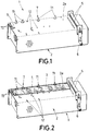
Figure 1 shows a perspective view of an example of the laminating machine for laminating acrylic license plates object of the invention, in which the main parts and elements the invention comprises, as well as the configuration and arrangement thereof, can be seen. -
Figures 2 and3 each shows a perspective view of the machine of the invention according to the example shown inFigure 1 , depicted with a plate incorporated thereon, specifically, in the laminating phase in the step before the insertion thereof in the rollers inFigure 2 , and in the step of insertion in the rollers inFigure 3 . -
Figure 4 shows an enlarged section view of a portion of the machine of the invention, also depicted with the plate incorporated thereon, in which the configuration and arrangement of the guide accessories the invention comprises to ensure that lamination is performed with the reflective film centered on the surface of the acrylic part can be seen. - In view of the mentioned drawings and according to the numbering used therein, a proposed non-limiting example of the laminating machine for laminating acrylic license plates, which comprises the parts and elements indicated and described in detail below, can be seen.
- In this sense, as seen in said drawings the laminator (1) in question is formed, as is known, from a prismatic body (2) with an upper base (2a), determining a rectangular surface suitable for incorporating the elements to be laminated consisting of at least an acrylic part (3) and a reflective film (4), and with rollers (5) located at one of the ends of said upper base (2a), where said elements (3, 4) arranged one on top of another are passed between said rollers for attaching them together, and where said rollers rotate in opposite directions upon actuating same, for example by means of a crank (6) coupled to the shaft of one of said rollers which the machine (1) also has.
- Based on this conventional configuration, the machine (1) is distinguished by having holding and guiding means (7) which immobilize the reflective film (4) such that it is centered with respect to the acrylic part (3) having a larger dimension than the reflective film such that said acrylic part (3) protrudes perimeter-wise with respect to the reflective film (4), and keep it in place by guiding both elements without them moving with respect to one another during the laminating process, both while inserting them between the rollers (5), and along almost the entire path traveled by the elements (3, 4) to be laminated through the rollers (5).
- Specifically, said holding and guiding means (7) are made up of a series of lateral guide accessories (71) incorporated in the body (2) of the machine, aligned along one of the sides of its upper base (2a), and at least two end guide accessories (72), on the side of the upper base (2a) opposite the side on which the rollers (5) are incorporated, located perpendicular to the lateral guide accessories (71) and parallel to the rollers (5) at a precise distance to enable incorporating the elements (3, 4) to be laminated between these end guide accessories (72) and the rollers (5).
- In reference to
Figure 4 , it can be seen how in the preferred embodiment said lateral guide accessories (71) and end guide accessories (72) are formed by a vertically projecting lug (7a) acting as a stop with the edge of the acrylic part (3) to keep it in the desired position, at the base of which there is a washer-like protruding circular wing (7b) acting as a stop with the edge of the reflective film (4) at a certain distance below the acrylic part (3). Based on the indicated difference in dimension between the reflective film (4) and the acrylic part (3), the dimension of said wing (7a) is the dimension required to keep the reflective film centered on the lower surface of the acrylic part on which it will be attached when passing between the rollers (5). - Furthermore, it can also be seen in said
Figure 4 how, while almost all the guide accessories (71, 72) are fixed to the upper base (2a) of the body (2) of the machine without the possibility of movement by means of nuts (8) screwed onto a threaded rod (7c) which emerges from the lower portion of the accessories, going through holes (12) made on said upper base (2a) for that purpose, at least one of the end guide accessories (72) is movable as it is inserted through a groove (9) in which it moves in order to get closer to the rollers (5) to a greater or lesser extent to continue holding and guiding the acrylic part (3) and the reflective film (4) when they are being inserted, at the opposite end, between the rollers (5). - Preferably, the upper base (2a) has multiple holes (12) for positioning the guide accessories (71, 72) in different locations, depending on the size of the elements to be laminated (3, 4) which will form the plate.
- To make the movement of this movable end guide accessory (72) easier, there is associated therewith, through the lower threaded rod (7c) and nut (8) holding it, a spring (10) incorporated in a housing (11) provided to that end under the groove (9), which tends to push it towards the rollers (5), as seen in
Figures 3 and 4 . - Having sufficiently described the nature of the present invention as well as the way of putting it into practice, it is not considered necessary to further describe the invention so that a person skilled in the art can comprehend the scope thereof and the advantages derived from it, stating that within its essential nature, the present invention could be carried out to practice in other embodiments differing in detail from that indicated by way of example, and such embodiments would also be granted the protection that is sought provided that the fundamental principle thereof is not altered, changed or modified.
Claims (6)
- A laminating machine for laminating acrylic license plates, particularly license plates consisting of at least an acrylic part (3) and a reflective film (4) having a smaller dimension than the acrylic part such that said acrylic part (3) protrudes perimeter-wise with respect to the reflective film (4), and said machine (1) comprising a prismatic body (2) with an upper base (2a), determining a rectangular surface suitable for incorporating the elements (3, 4) to be laminated, and rollers (5) located at one of the ends of said upper base (2a), where said elements (3, 4) arranged one on top of another are passed between said rollers for attaching them together, and where said rollers rotate in opposite directions upon actuating same, for example by means of a crank (6) coupled to the shaft of one of said rollers, the machine being characterized by having holding and guiding means (7) which immobilize the reflective film (4) such that it is centered with respect to the acrylic part (3), and keep it in place, guiding both elements (3, 4) without them moving with respect to one another during the laminating process, both while inserting them between the rollers (5), and along almost the entire path traveled by the elements (3, 4) to be laminated through the rollers (5).
- The laminating machine for laminating acrylic license plates according to claim 1, characterized in that the holding and guiding means (7) are made up of a series of lateral guide accessories (71), incorporated in the body (2) of the machine, aligned along one of the sides of the upper base (2a) thereof, and at least two end guide accessories (72), incorporated on the side of the upper base (2a) opposite the side on which the rollers (5) are incorporated and located perpendicular to the lateral guide accessories (71) and parallel to the rollers (5) at a precise distance to enable incorporating the elements (3, 4) to be laminated between these end guide accessories (72) and the rollers (5).
- The laminating machine for laminating acrylic license plates according to claim 2, characterized in that the lateral guide accessories (71) and end guide accessories (72) are formed by a vertically projecting lug (7a), acting as a stop with the edge of the acrylic part (3) to keep it in the desired position, at the base of which there is a washer-like protruding circular wing (7b) acting as a stop with the edge of the reflective film (4) at a certain distance below the acrylic part (3); where the dimension of said wing (7a) is adjusted to the difference in dimension between the reflective film (4) and the acrylic part (3).
- The laminating machine for laminating acrylic license plates according to any of claims 2 or 3, characterized in that all the guide accessories (71, 72) are fixed to the upper base (2a) of the body (2) of the machine without the possibility of movement, with the exception of at least one of the end guide accessories (72) which is movable as it is inserted through a groove (9) in which it moves in order to get closer to the rollers (5) to a greater or lesser extent.
- The laminating machine for laminating acrylic license plates according to claim 4, characterized in that the end guide accessory (72) which is movable is associated with a spring (10), incorporated in a housing (11) provided to that end under the groove (9), which tends to push it towards the rollers (5).
- The laminating machine for laminating acrylic license plates according to any of claims 2 to 5, characterized in that the upper base (2a) has multiple holes (12) for positioning the guide accessories (71, 72) in different locations, depending on the size of the elements to be laminated (3, 4) forming the plate.
Applications Claiming Priority (1)
| Application Number | Priority Date | Filing Date | Title |
|---|---|---|---|
| ES201730111A ES2677369B1 (en) | 2017-01-31 | 2017-01-31 | ACRYLIC ENROLLMENT PLATE LAMINATOR MACHINE |
Publications (2)
| Publication Number | Publication Date |
|---|---|
| EP3354458A1 true EP3354458A1 (en) | 2018-08-01 |
| EP3354458B1 EP3354458B1 (en) | 2020-01-08 |
Family
ID=61094351
Family Applications (1)
| Application Number | Title | Priority Date | Filing Date |
|---|---|---|---|
| EP18154212.7A Active EP3354458B1 (en) | 2017-01-31 | 2018-01-30 | Laminating machine for laminating acrylic license plates |
Country Status (4)
| Country | Link |
|---|---|
| EP (1) | EP3354458B1 (en) |
| ES (2) | ES2677369B1 (en) |
| PT (1) | PT3354458T (en) |
| ZA (1) | ZA201800554B (en) |
Cited By (2)
| Publication number | Priority date | Publication date | Assignee | Title |
|---|---|---|---|---|
| EP3722097A1 (en) * | 2019-04-08 | 2020-10-14 | Industrias Samar't, S.A. | Method for manufacturing and painting characters press formed on license plates and tubular thermal-transfer film for carrying out said method |
| ES2891789A1 (en) * | 2020-07-23 | 2022-01-31 | Ind Samart Sa | PORTABLE LAMINATING MACHINE FOR THERMAL STAMPING OF LICENSE PLATE (Machine-translation by Google Translate, not legally binding) |
Families Citing this family (1)
| Publication number | Priority date | Publication date | Assignee | Title |
|---|---|---|---|---|
| ES2930061B2 (en) * | 2021-06-03 | 2023-04-10 | Ind Samart Sa | TENSIONING DEVICE FOR LICENSE PLATE LAMINATING MACHINE |
Citations (3)
| Publication number | Priority date | Publication date | Assignee | Title |
|---|---|---|---|---|
| GB2322466A (en) * | 1997-10-21 | 1998-08-26 | Sandhurst Autoprint Ltd | An apparatus for assembly of an identification plate |
| ES1080455U (en) * | 2013-04-23 | 2013-05-30 | Traffic Futura 2007, S.L.U. | Laminating device for acrylic plates (Machine-translation by Google Translate, not legally binding) |
| FR3011767A1 (en) * | 2013-10-10 | 2015-04-17 | Minnesota Mining Mfg France | UNIVERSAL MACHINE FOR MANUFACTURING INFORMATIVE PANELS |
Family Cites Families (1)
| Publication number | Priority date | Publication date | Assignee | Title |
|---|---|---|---|---|
| GB9700543D0 (en) * | 1997-01-13 | 1997-03-05 | Statefresh Limited | Number plate registration board |
-
2017
- 2017-01-31 ES ES201730111A patent/ES2677369B1/en active Active
-
2018
- 2018-01-26 ZA ZA2018/00554A patent/ZA201800554B/en unknown
- 2018-01-30 EP EP18154212.7A patent/EP3354458B1/en active Active
- 2018-01-30 ES ES18154212T patent/ES2779899T3/en active Active
- 2018-01-30 PT PT181542127T patent/PT3354458T/en unknown
Patent Citations (3)
| Publication number | Priority date | Publication date | Assignee | Title |
|---|---|---|---|---|
| GB2322466A (en) * | 1997-10-21 | 1998-08-26 | Sandhurst Autoprint Ltd | An apparatus for assembly of an identification plate |
| ES1080455U (en) * | 2013-04-23 | 2013-05-30 | Traffic Futura 2007, S.L.U. | Laminating device for acrylic plates (Machine-translation by Google Translate, not legally binding) |
| FR3011767A1 (en) * | 2013-10-10 | 2015-04-17 | Minnesota Mining Mfg France | UNIVERSAL MACHINE FOR MANUFACTURING INFORMATIVE PANELS |
Non-Patent Citations (1)
| Title |
|---|
| UNKNOWN: "Alignment Jigs -Tennants UK Ltd", 22 December 2016 (2016-12-22), XP055477816, Retrieved from the Internet <URL:https://web.archive.org/web/20161222175726/http://www.tennantsuk.com/alignment-jigs/> [retrieved on 20180523] * |
Cited By (2)
| Publication number | Priority date | Publication date | Assignee | Title |
|---|---|---|---|---|
| EP3722097A1 (en) * | 2019-04-08 | 2020-10-14 | Industrias Samar't, S.A. | Method for manufacturing and painting characters press formed on license plates and tubular thermal-transfer film for carrying out said method |
| ES2891789A1 (en) * | 2020-07-23 | 2022-01-31 | Ind Samart Sa | PORTABLE LAMINATING MACHINE FOR THERMAL STAMPING OF LICENSE PLATE (Machine-translation by Google Translate, not legally binding) |
Also Published As
| Publication number | Publication date |
|---|---|
| ES2677369B1 (en) | 2019-05-23 |
| ES2779899T3 (en) | 2020-08-20 |
| EP3354458B1 (en) | 2020-01-08 |
| PT3354458T (en) | 2020-05-29 |
| ZA201800554B (en) | 2018-11-28 |
| ES2677369A1 (en) | 2018-08-01 |
Similar Documents
| Publication | Publication Date | Title |
|---|---|---|
| EP3354458A1 (en) | Laminating machine for laminating acrylic license plates | |
| EP3366472A1 (en) | Laminating machine for laminating three-layer acrylic license plates | |
| DK146019B (en) | APPARATUS FOR USE IN THE MANUFACTURE OF A SEAL STAMP | |
| US20140020332A1 (en) | Film affixing apparatus | |
| EP3079991A1 (en) | Packaging device | |
| US20140020843A1 (en) | Machine for cutting object and sticking film | |
| US20060266590A1 (en) | Gradual catch system for a bidirectional safety device | |
| EP3482936A1 (en) | Platform structure of 3d printer and carrier thereof | |
| KR101229219B1 (en) | A mold of die cutter and setting structure of a mold | |
| JP2016042048A5 (en) | ||
| US3732769A (en) | Device for applying slide transparency to mounting | |
| US1959602A (en) | Perforating machine | |
| WO2017158090A1 (en) | Cartesian machine tool with horizontal slide and cantilevered machining head, and slide carriage for such machine tool | |
| KR102039800B1 (en) | Apparatus for Press-Fitting the Bushing in the Burring type of Arm using Spring Back Correction | |
| KR101896383B1 (en) | Vision aligning apparatus for vacuum laminator | |
| GB1321928A (en) | Device for repairing punch tape | |
| US1759025A (en) | Miter-cutting machine for pattern binding | |
| US720099A (en) | Slide-shifter for magic lanterns. | |
| US20130284566A1 (en) | Conveyance tray and conveyance system thereof | |
| US2359719A (en) | Method of facing metal plates | |
| CN104942147A (en) | Multidirectional locating and stamping die | |
| KR101919548B1 (en) | Apparatus for separating of blank panel | |
| KR101548731B1 (en) | tape cartridge | |
| CN104668584A (en) | Turn broach machine | |
| US1696834A (en) | Bed for shoe-ornamenting machinery |
Legal Events
| Date | Code | Title | Description |
|---|---|---|---|
| PUAI | Public reference made under article 153(3) epc to a published international application that has entered the european phase |
Free format text: ORIGINAL CODE: 0009012 |
|
| STAA | Information on the status of an ep patent application or granted ep patent |
Free format text: STATUS: REQUEST FOR EXAMINATION WAS MADE |
|
| 17P | Request for examination filed |
Effective date: 20180130 |
|
| AK | Designated contracting states |
Kind code of ref document: A1 Designated state(s): AL AT BE BG CH CY CZ DE DK EE ES FI FR GB GR HR HU IE IS IT LI LT LU LV MC MK MT NL NO PL PT RO RS SE SI SK SM TR |
|
| AX | Request for extension of the european patent |
Extension state: BA ME |
|
| STAA | Information on the status of an ep patent application or granted ep patent |
Free format text: STATUS: EXAMINATION IS IN PROGRESS |
|
| 17Q | First examination report despatched |
Effective date: 20190513 |
|
| REG | Reference to a national code |
Ref country code: DE Ref legal event code: R079 Ref document number: 602018001924 Country of ref document: DE Free format text: PREVIOUS MAIN CLASS: B32B0038180000 Ipc: B32B0041000000 |
|
| GRAP | Despatch of communication of intention to grant a patent |
Free format text: ORIGINAL CODE: EPIDOSNIGR1 |
|
| STAA | Information on the status of an ep patent application or granted ep patent |
Free format text: STATUS: GRANT OF PATENT IS INTENDED |
|
| RIC1 | Information provided on ipc code assigned before grant |
Ipc: B60R 13/10 20060101ALN20190625BHEP Ipc: B32B 41/00 20060101AFI20190625BHEP Ipc: B32B 38/18 20060101ALI20190625BHEP |
|
| INTG | Intention to grant announced |
Effective date: 20190729 |
|
| GRAS | Grant fee paid |
Free format text: ORIGINAL CODE: EPIDOSNIGR3 |
|
| GRAA | (expected) grant |
Free format text: ORIGINAL CODE: 0009210 |
|
| STAA | Information on the status of an ep patent application or granted ep patent |
Free format text: STATUS: THE PATENT HAS BEEN GRANTED |
|
| AK | Designated contracting states |
Kind code of ref document: B1 Designated state(s): AL AT BE BG CH CY CZ DE DK EE ES FI FR GB GR HR HU IE IS IT LI LT LU LV MC MK MT NL NO PL PT RO RS SE SI SK SM TR |
|
| REG | Reference to a national code |
Ref country code: GB Ref legal event code: FG4D |
|
| REG | Reference to a national code |
Ref country code: CH Ref legal event code: EP |
|
| REG | Reference to a national code |
Ref country code: DE Ref legal event code: R096 Ref document number: 602018001924 Country of ref document: DE |
|
| REG | Reference to a national code |
Ref country code: IE Ref legal event code: FG4D |
|
| REG | Reference to a national code |
Ref country code: AT Ref legal event code: REF Ref document number: 1222190 Country of ref document: AT Kind code of ref document: T Effective date: 20200215 |
|
| REG | Reference to a national code |
Ref country code: NL Ref legal event code: MP Effective date: 20200108 |
|
| REG | Reference to a national code |
Ref country code: PT Ref legal event code: SC4A Ref document number: 3354458 Country of ref document: PT Date of ref document: 20200529 Kind code of ref document: T Free format text: AVAILABILITY OF NATIONAL TRANSLATION Effective date: 20200521 |
|
| REG | Reference to a national code |
Ref country code: LT Ref legal event code: MG4D |
|
| PG25 | Lapsed in a contracting state [announced via postgrant information from national office to epo] |
Ref country code: RS Free format text: LAPSE BECAUSE OF FAILURE TO SUBMIT A TRANSLATION OF THE DESCRIPTION OR TO PAY THE FEE WITHIN THE PRESCRIBED TIME-LIMIT Effective date: 20200108 Ref country code: NO Free format text: LAPSE BECAUSE OF FAILURE TO SUBMIT A TRANSLATION OF THE DESCRIPTION OR TO PAY THE FEE WITHIN THE PRESCRIBED TIME-LIMIT Effective date: 20200408 Ref country code: FI Free format text: LAPSE BECAUSE OF FAILURE TO SUBMIT A TRANSLATION OF THE DESCRIPTION OR TO PAY THE FEE WITHIN THE PRESCRIBED TIME-LIMIT Effective date: 20200108 Ref country code: LT Free format text: LAPSE BECAUSE OF FAILURE TO SUBMIT A TRANSLATION OF THE DESCRIPTION OR TO PAY THE FEE WITHIN THE PRESCRIBED TIME-LIMIT Effective date: 20200108 Ref country code: NL Free format text: LAPSE BECAUSE OF FAILURE TO SUBMIT A TRANSLATION OF THE DESCRIPTION OR TO PAY THE FEE WITHIN THE PRESCRIBED TIME-LIMIT Effective date: 20200108 |
|
| REG | Reference to a national code |
Ref country code: DE Ref legal event code: R119 Ref document number: 602018001924 Country of ref document: DE |
|
| REG | Reference to a national code |
Ref country code: ES Ref legal event code: FG2A Ref document number: 2779899 Country of ref document: ES Kind code of ref document: T3 Effective date: 20200820 |
|
| PG25 | Lapsed in a contracting state [announced via postgrant information from national office to epo] |
Ref country code: IS Free format text: LAPSE BECAUSE OF FAILURE TO SUBMIT A TRANSLATION OF THE DESCRIPTION OR TO PAY THE FEE WITHIN THE PRESCRIBED TIME-LIMIT Effective date: 20200508 Ref country code: LV Free format text: LAPSE BECAUSE OF FAILURE TO SUBMIT A TRANSLATION OF THE DESCRIPTION OR TO PAY THE FEE WITHIN THE PRESCRIBED TIME-LIMIT Effective date: 20200108 Ref country code: SE Free format text: LAPSE BECAUSE OF FAILURE TO SUBMIT A TRANSLATION OF THE DESCRIPTION OR TO PAY THE FEE WITHIN THE PRESCRIBED TIME-LIMIT Effective date: 20200108 Ref country code: GR Free format text: LAPSE BECAUSE OF FAILURE TO SUBMIT A TRANSLATION OF THE DESCRIPTION OR TO PAY THE FEE WITHIN THE PRESCRIBED TIME-LIMIT Effective date: 20200409 Ref country code: BG Free format text: LAPSE BECAUSE OF FAILURE TO SUBMIT A TRANSLATION OF THE DESCRIPTION OR TO PAY THE FEE WITHIN THE PRESCRIBED TIME-LIMIT Effective date: 20200408 Ref country code: HR Free format text: LAPSE BECAUSE OF FAILURE TO SUBMIT A TRANSLATION OF THE DESCRIPTION OR TO PAY THE FEE WITHIN THE PRESCRIBED TIME-LIMIT Effective date: 20200108 |
|
| PG25 | Lapsed in a contracting state [announced via postgrant information from national office to epo] |
Ref country code: DE Free format text: LAPSE BECAUSE OF NON-PAYMENT OF DUE FEES Effective date: 20200801 Ref country code: SK Free format text: LAPSE BECAUSE OF FAILURE TO SUBMIT A TRANSLATION OF THE DESCRIPTION OR TO PAY THE FEE WITHIN THE PRESCRIBED TIME-LIMIT Effective date: 20200108 Ref country code: LU Free format text: LAPSE BECAUSE OF NON-PAYMENT OF DUE FEES Effective date: 20200130 Ref country code: MC Free format text: LAPSE BECAUSE OF FAILURE TO SUBMIT A TRANSLATION OF THE DESCRIPTION OR TO PAY THE FEE WITHIN THE PRESCRIBED TIME-LIMIT Effective date: 20200108 Ref country code: CZ Free format text: LAPSE BECAUSE OF FAILURE TO SUBMIT A TRANSLATION OF THE DESCRIPTION OR TO PAY THE FEE WITHIN THE PRESCRIBED TIME-LIMIT Effective date: 20200108 Ref country code: RO Free format text: LAPSE BECAUSE OF FAILURE TO SUBMIT A TRANSLATION OF THE DESCRIPTION OR TO PAY THE FEE WITHIN THE PRESCRIBED TIME-LIMIT Effective date: 20200108 Ref country code: DK Free format text: LAPSE BECAUSE OF FAILURE TO SUBMIT A TRANSLATION OF THE DESCRIPTION OR TO PAY THE FEE WITHIN THE PRESCRIBED TIME-LIMIT Effective date: 20200108 Ref country code: SM Free format text: LAPSE BECAUSE OF FAILURE TO SUBMIT A TRANSLATION OF THE DESCRIPTION OR TO PAY THE FEE WITHIN THE PRESCRIBED TIME-LIMIT Effective date: 20200108 Ref country code: EE Free format text: LAPSE BECAUSE OF FAILURE TO SUBMIT A TRANSLATION OF THE DESCRIPTION OR TO PAY THE FEE WITHIN THE PRESCRIBED TIME-LIMIT Effective date: 20200108 |
|
| PLBE | No opposition filed within time limit |
Free format text: ORIGINAL CODE: 0009261 |
|
| STAA | Information on the status of an ep patent application or granted ep patent |
Free format text: STATUS: NO OPPOSITION FILED WITHIN TIME LIMIT |
|
| REG | Reference to a national code |
Ref country code: AT Ref legal event code: MK05 Ref document number: 1222190 Country of ref document: AT Kind code of ref document: T Effective date: 20200108 |
|
| 26N | No opposition filed |
Effective date: 20201009 |
|
| PG25 | Lapsed in a contracting state [announced via postgrant information from national office to epo] |
Ref country code: IE Free format text: LAPSE BECAUSE OF NON-PAYMENT OF DUE FEES Effective date: 20200130 Ref country code: AT Free format text: LAPSE BECAUSE OF FAILURE TO SUBMIT A TRANSLATION OF THE DESCRIPTION OR TO PAY THE FEE WITHIN THE PRESCRIBED TIME-LIMIT Effective date: 20200108 Ref country code: IT Free format text: LAPSE BECAUSE OF FAILURE TO SUBMIT A TRANSLATION OF THE DESCRIPTION OR TO PAY THE FEE WITHIN THE PRESCRIBED TIME-LIMIT Effective date: 20200108 |
|
| PG25 | Lapsed in a contracting state [announced via postgrant information from national office to epo] |
Ref country code: SI Free format text: LAPSE BECAUSE OF FAILURE TO SUBMIT A TRANSLATION OF THE DESCRIPTION OR TO PAY THE FEE WITHIN THE PRESCRIBED TIME-LIMIT Effective date: 20200108 Ref country code: PL Free format text: LAPSE BECAUSE OF FAILURE TO SUBMIT A TRANSLATION OF THE DESCRIPTION OR TO PAY THE FEE WITHIN THE PRESCRIBED TIME-LIMIT Effective date: 20200108 |
|
| REG | Reference to a national code |
Ref country code: CH Ref legal event code: PL |
|
| PG25 | Lapsed in a contracting state [announced via postgrant information from national office to epo] |
Ref country code: LI Free format text: LAPSE BECAUSE OF NON-PAYMENT OF DUE FEES Effective date: 20210131 Ref country code: CH Free format text: LAPSE BECAUSE OF NON-PAYMENT OF DUE FEES Effective date: 20210131 |
|
| PG25 | Lapsed in a contracting state [announced via postgrant information from national office to epo] |
Ref country code: TR Free format text: LAPSE BECAUSE OF FAILURE TO SUBMIT A TRANSLATION OF THE DESCRIPTION OR TO PAY THE FEE WITHIN THE PRESCRIBED TIME-LIMIT Effective date: 20200108 Ref country code: MT Free format text: LAPSE BECAUSE OF FAILURE TO SUBMIT A TRANSLATION OF THE DESCRIPTION OR TO PAY THE FEE WITHIN THE PRESCRIBED TIME-LIMIT Effective date: 20200108 Ref country code: CY Free format text: LAPSE BECAUSE OF FAILURE TO SUBMIT A TRANSLATION OF THE DESCRIPTION OR TO PAY THE FEE WITHIN THE PRESCRIBED TIME-LIMIT Effective date: 20200108 |
|
| PG25 | Lapsed in a contracting state [announced via postgrant information from national office to epo] |
Ref country code: MK Free format text: LAPSE BECAUSE OF FAILURE TO SUBMIT A TRANSLATION OF THE DESCRIPTION OR TO PAY THE FEE WITHIN THE PRESCRIBED TIME-LIMIT Effective date: 20200108 Ref country code: AL Free format text: LAPSE BECAUSE OF FAILURE TO SUBMIT A TRANSLATION OF THE DESCRIPTION OR TO PAY THE FEE WITHIN THE PRESCRIBED TIME-LIMIT Effective date: 20200108 |
|
| PGFP | Annual fee paid to national office [announced via postgrant information from national office to epo] |
Ref country code: GB Payment date: 20251210 Year of fee payment: 9 |
|
| PGFP | Annual fee paid to national office [announced via postgrant information from national office to epo] |
Ref country code: PT Payment date: 20251210 Year of fee payment: 9 |
|
| PGFP | Annual fee paid to national office [announced via postgrant information from national office to epo] |
Ref country code: ES Payment date: 20260211 Year of fee payment: 9 |
|
| PGFP | Annual fee paid to national office [announced via postgrant information from national office to epo] |
Ref country code: BE Payment date: 20260121 Year of fee payment: 9 |
|
| PGFP | Annual fee paid to national office [announced via postgrant information from national office to epo] |
Ref country code: FR Payment date: 20260119 Year of fee payment: 9 |