EP3354444B1 - Verfahren zur herstellung eines bauteils - Google Patents
Verfahren zur herstellung eines bauteils Download PDFInfo
- Publication number
- EP3354444B1 EP3354444B1 EP18154236.6A EP18154236A EP3354444B1 EP 3354444 B1 EP3354444 B1 EP 3354444B1 EP 18154236 A EP18154236 A EP 18154236A EP 3354444 B1 EP3354444 B1 EP 3354444B1
- Authority
- EP
- European Patent Office
- Prior art keywords
- component
- structural element
- adhesive layer
- fibre
- temperature
- Prior art date
- Legal status (The legal status is an assumption and is not a legal conclusion. Google has not performed a legal analysis and makes no representation as to the accuracy of the status listed.)
- Active
Links
Images

Classifications
-
- B—PERFORMING OPERATIONS; TRANSPORTING
- B29—WORKING OF PLASTICS; WORKING OF SUBSTANCES IN A PLASTIC STATE IN GENERAL
- B29C—SHAPING OR JOINING OF PLASTICS; SHAPING OF MATERIAL IN A PLASTIC STATE, NOT OTHERWISE PROVIDED FOR; AFTER-TREATMENT OF THE SHAPED PRODUCTS, e.g. REPAIRING
- B29C65/00—Joining or sealing of preformed parts, e.g. welding of plastics materials; Apparatus therefor
- B29C65/48—Joining or sealing of preformed parts, e.g. welding of plastics materials; Apparatus therefor using adhesives, i.e. using supplementary joining material; solvent bonding
- B29C65/4805—Joining or sealing of preformed parts, e.g. welding of plastics materials; Apparatus therefor using adhesives, i.e. using supplementary joining material; solvent bonding characterised by the type of adhesives
- B29C65/483—Reactive adhesives, e.g. chemically curing adhesives
- B29C65/4835—Heat curing adhesives
-
- B—PERFORMING OPERATIONS; TRANSPORTING
- B29—WORKING OF PLASTICS; WORKING OF SUBSTANCES IN A PLASTIC STATE IN GENERAL
- B29C—SHAPING OR JOINING OF PLASTICS; SHAPING OF MATERIAL IN A PLASTIC STATE, NOT OTHERWISE PROVIDED FOR; AFTER-TREATMENT OF THE SHAPED PRODUCTS, e.g. REPAIRING
- B29C65/00—Joining or sealing of preformed parts, e.g. welding of plastics materials; Apparatus therefor
- B29C65/02—Joining or sealing of preformed parts, e.g. welding of plastics materials; Apparatus therefor by heating, with or without pressure
- B29C65/10—Joining or sealing of preformed parts, e.g. welding of plastics materials; Apparatus therefor by heating, with or without pressure using hot gases (e.g. combustion gases) or flames coming in contact with at least one of the parts to be joined
-
- B—PERFORMING OPERATIONS; TRANSPORTING
- B29—WORKING OF PLASTICS; WORKING OF SUBSTANCES IN A PLASTIC STATE IN GENERAL
- B29C—SHAPING OR JOINING OF PLASTICS; SHAPING OF MATERIAL IN A PLASTIC STATE, NOT OTHERWISE PROVIDED FOR; AFTER-TREATMENT OF THE SHAPED PRODUCTS, e.g. REPAIRING
- B29C65/00—Joining or sealing of preformed parts, e.g. welding of plastics materials; Apparatus therefor
- B29C65/02—Joining or sealing of preformed parts, e.g. welding of plastics materials; Apparatus therefor by heating, with or without pressure
- B29C65/34—Joining or sealing of preformed parts, e.g. welding of plastics materials; Apparatus therefor by heating, with or without pressure using heated elements which remain in the joint, e.g. "verlorenes Schweisselement"
- B29C65/36—Joining or sealing of preformed parts, e.g. welding of plastics materials; Apparatus therefor by heating, with or without pressure using heated elements which remain in the joint, e.g. "verlorenes Schweisselement" heated by induction
- B29C65/3604—Joining or sealing of preformed parts, e.g. welding of plastics materials; Apparatus therefor by heating, with or without pressure using heated elements which remain in the joint, e.g. "verlorenes Schweisselement" heated by induction characterised by the type of elements heated by induction which remain in the joint
- B29C65/3656—Joining or sealing of preformed parts, e.g. welding of plastics materials; Apparatus therefor by heating, with or without pressure using heated elements which remain in the joint, e.g. "verlorenes Schweisselement" heated by induction characterised by the type of elements heated by induction which remain in the joint being a layer of a multilayer part to be joined, e.g. for joining plastic-metal laminates
-
- B—PERFORMING OPERATIONS; TRANSPORTING
- B29—WORKING OF PLASTICS; WORKING OF SUBSTANCES IN A PLASTIC STATE IN GENERAL
- B29C—SHAPING OR JOINING OF PLASTICS; SHAPING OF MATERIAL IN A PLASTIC STATE, NOT OTHERWISE PROVIDED FOR; AFTER-TREATMENT OF THE SHAPED PRODUCTS, e.g. REPAIRING
- B29C65/00—Joining or sealing of preformed parts, e.g. welding of plastics materials; Apparatus therefor
- B29C65/78—Means for handling the parts to be joined, e.g. for making containers or hollow articles, e.g. means for handling sheets, plates, web-like materials, tubular articles, hollow articles or elements to be joined therewith; Means for discharging the joined articles from the joining apparatus
- B29C65/7855—Provisory fixing
-
- B—PERFORMING OPERATIONS; TRANSPORTING
- B29—WORKING OF PLASTICS; WORKING OF SUBSTANCES IN A PLASTIC STATE IN GENERAL
- B29C—SHAPING OR JOINING OF PLASTICS; SHAPING OF MATERIAL IN A PLASTIC STATE, NOT OTHERWISE PROVIDED FOR; AFTER-TREATMENT OF THE SHAPED PRODUCTS, e.g. REPAIRING
- B29C66/00—General aspects of processes or apparatus for joining preformed parts
- B29C66/01—General aspects dealing with the joint area or with the area to be joined
- B29C66/05—Particular design of joint configurations
- B29C66/10—Particular design of joint configurations particular design of the joint cross-sections
- B29C66/11—Joint cross-sections comprising a single joint-segment, i.e. one of the parts to be joined comprising a single joint-segment in the joint cross-section
- B29C66/112—Single lapped joints
-
- B—PERFORMING OPERATIONS; TRANSPORTING
- B29—WORKING OF PLASTICS; WORKING OF SUBSTANCES IN A PLASTIC STATE IN GENERAL
- B29C—SHAPING OR JOINING OF PLASTICS; SHAPING OF MATERIAL IN A PLASTIC STATE, NOT OTHERWISE PROVIDED FOR; AFTER-TREATMENT OF THE SHAPED PRODUCTS, e.g. REPAIRING
- B29C66/00—General aspects of processes or apparatus for joining preformed parts
- B29C66/01—General aspects dealing with the joint area or with the area to be joined
- B29C66/05—Particular design of joint configurations
- B29C66/10—Particular design of joint configurations particular design of the joint cross-sections
- B29C66/13—Single flanged joints; Fin-type joints; Single hem joints; Edge joints; Interpenetrating fingered joints; Other specific particular designs of joint cross-sections not provided for in groups B29C66/11 - B29C66/12
- B29C66/131—Single flanged joints, i.e. one of the parts to be joined being rigid and flanged in the joint area
-
- B—PERFORMING OPERATIONS; TRANSPORTING
- B29—WORKING OF PLASTICS; WORKING OF SUBSTANCES IN A PLASTIC STATE IN GENERAL
- B29C—SHAPING OR JOINING OF PLASTICS; SHAPING OF MATERIAL IN A PLASTIC STATE, NOT OTHERWISE PROVIDED FOR; AFTER-TREATMENT OF THE SHAPED PRODUCTS, e.g. REPAIRING
- B29C66/00—General aspects of processes or apparatus for joining preformed parts
- B29C66/01—General aspects dealing with the joint area or with the area to be joined
- B29C66/05—Particular design of joint configurations
- B29C66/20—Particular design of joint configurations particular design of the joint lines, e.g. of the weld lines
- B29C66/21—Particular design of joint configurations particular design of the joint lines, e.g. of the weld lines said joint lines being formed by a single dot or dash or by several dots or dashes, i.e. spot joining or spot welding
-
- B—PERFORMING OPERATIONS; TRANSPORTING
- B29—WORKING OF PLASTICS; WORKING OF SUBSTANCES IN A PLASTIC STATE IN GENERAL
- B29C—SHAPING OR JOINING OF PLASTICS; SHAPING OF MATERIAL IN A PLASTIC STATE, NOT OTHERWISE PROVIDED FOR; AFTER-TREATMENT OF THE SHAPED PRODUCTS, e.g. REPAIRING
- B29C66/00—General aspects of processes or apparatus for joining preformed parts
- B29C66/40—General aspects of joining substantially flat articles, e.g. plates, sheets or web-like materials; Making flat seams in tubular or hollow articles; Joining single elements to substantially flat surfaces
- B29C66/47—Joining single elements to sheets, plates or other substantially flat surfaces
- B29C66/474—Joining single elements to sheets, plates or other substantially flat surfaces said single elements being substantially non-flat
-
- B—PERFORMING OPERATIONS; TRANSPORTING
- B29—WORKING OF PLASTICS; WORKING OF SUBSTANCES IN A PLASTIC STATE IN GENERAL
- B29C—SHAPING OR JOINING OF PLASTICS; SHAPING OF MATERIAL IN A PLASTIC STATE, NOT OTHERWISE PROVIDED FOR; AFTER-TREATMENT OF THE SHAPED PRODUCTS, e.g. REPAIRING
- B29C66/00—General aspects of processes or apparatus for joining preformed parts
- B29C66/50—General aspects of joining tubular articles; General aspects of joining long products, i.e. bars or profiled elements; General aspects of joining single elements to tubular articles, hollow articles or bars; General aspects of joining several hollow-preforms to form hollow or tubular articles
- B29C66/51—Joining tubular articles, profiled elements or bars; Joining single elements to tubular articles, hollow articles or bars; Joining several hollow-preforms to form hollow or tubular articles
- B29C66/52—Joining tubular articles, bars or profiled elements
- B29C66/524—Joining profiled elements
-
- B—PERFORMING OPERATIONS; TRANSPORTING
- B29—WORKING OF PLASTICS; WORKING OF SUBSTANCES IN A PLASTIC STATE IN GENERAL
- B29C—SHAPING OR JOINING OF PLASTICS; SHAPING OF MATERIAL IN A PLASTIC STATE, NOT OTHERWISE PROVIDED FOR; AFTER-TREATMENT OF THE SHAPED PRODUCTS, e.g. REPAIRING
- B29C66/00—General aspects of processes or apparatus for joining preformed parts
- B29C66/70—General aspects of processes or apparatus for joining preformed parts characterised by the composition, physical properties or the structure of the material of the parts to be joined; Joining with non-plastics material
- B29C66/72—General aspects of processes or apparatus for joining preformed parts characterised by the composition, physical properties or the structure of the material of the parts to be joined; Joining with non-plastics material characterised by the structure of the material of the parts to be joined
- B29C66/721—Fibre-reinforced materials
-
- B—PERFORMING OPERATIONS; TRANSPORTING
- B29—WORKING OF PLASTICS; WORKING OF SUBSTANCES IN A PLASTIC STATE IN GENERAL
- B29C—SHAPING OR JOINING OF PLASTICS; SHAPING OF MATERIAL IN A PLASTIC STATE, NOT OTHERWISE PROVIDED FOR; AFTER-TREATMENT OF THE SHAPED PRODUCTS, e.g. REPAIRING
- B29C66/00—General aspects of processes or apparatus for joining preformed parts
- B29C66/70—General aspects of processes or apparatus for joining preformed parts characterised by the composition, physical properties or the structure of the material of the parts to be joined; Joining with non-plastics material
- B29C66/72—General aspects of processes or apparatus for joining preformed parts characterised by the composition, physical properties or the structure of the material of the parts to be joined; Joining with non-plastics material characterised by the structure of the material of the parts to be joined
- B29C66/723—General aspects of processes or apparatus for joining preformed parts characterised by the composition, physical properties or the structure of the material of the parts to be joined; Joining with non-plastics material characterised by the structure of the material of the parts to be joined being multi-layered
- B29C66/7232—General aspects of processes or apparatus for joining preformed parts characterised by the composition, physical properties or the structure of the material of the parts to be joined; Joining with non-plastics material characterised by the structure of the material of the parts to be joined being multi-layered comprising a non-plastics layer
- B29C66/72321—General aspects of processes or apparatus for joining preformed parts characterised by the composition, physical properties or the structure of the material of the parts to be joined; Joining with non-plastics material characterised by the structure of the material of the parts to be joined being multi-layered comprising a non-plastics layer consisting of metals or their alloys
-
- B—PERFORMING OPERATIONS; TRANSPORTING
- B29—WORKING OF PLASTICS; WORKING OF SUBSTANCES IN A PLASTIC STATE IN GENERAL
- B29C—SHAPING OR JOINING OF PLASTICS; SHAPING OF MATERIAL IN A PLASTIC STATE, NOT OTHERWISE PROVIDED FOR; AFTER-TREATMENT OF THE SHAPED PRODUCTS, e.g. REPAIRING
- B29C66/00—General aspects of processes or apparatus for joining preformed parts
- B29C66/90—Measuring or controlling the joining process
- B29C66/91—Measuring or controlling the joining process by measuring or controlling the temperature, the heat or the thermal flux
- B29C66/914—Measuring or controlling the joining process by measuring or controlling the temperature, the heat or the thermal flux by controlling or regulating the temperature, the heat or the thermal flux
- B29C66/9161—Measuring or controlling the joining process by measuring or controlling the temperature, the heat or the thermal flux by controlling or regulating the temperature, the heat or the thermal flux by controlling or regulating the heat or the thermal flux, i.e. the heat flux
- B29C66/91641—Measuring or controlling the joining process by measuring or controlling the temperature, the heat or the thermal flux by controlling or regulating the temperature, the heat or the thermal flux by controlling or regulating the heat or the thermal flux, i.e. the heat flux the heat or the thermal flux being non-constant over time
- B29C66/91643—Measuring or controlling the joining process by measuring or controlling the temperature, the heat or the thermal flux by controlling or regulating the temperature, the heat or the thermal flux by controlling or regulating the heat or the thermal flux, i.e. the heat flux the heat or the thermal flux being non-constant over time following a heat-time profile
- B29C66/91645—Measuring or controlling the joining process by measuring or controlling the temperature, the heat or the thermal flux by controlling or regulating the temperature, the heat or the thermal flux by controlling or regulating the heat or the thermal flux, i.e. the heat flux the heat or the thermal flux being non-constant over time following a heat-time profile by steps
-
- B—PERFORMING OPERATIONS; TRANSPORTING
- B29—WORKING OF PLASTICS; WORKING OF SUBSTANCES IN A PLASTIC STATE IN GENERAL
- B29L—INDEXING SCHEME ASSOCIATED WITH SUBCLASS B29C, RELATING TO PARTICULAR ARTICLES
- B29L2031/00—Other particular articles
- B29L2031/30—Vehicles, e.g. ships or aircraft, or body parts thereof
- B29L2031/3076—Aircrafts
Definitions
- the invention relates to a method for producing a component from at least two components to be glued together.
- fiber composite materials in the aerospace industry as well as in the automotive industry has established itself due to the advantageous properties of these materials. Nevertheless, such fiber composite materials are not free from disadvantages.
- fiber composite hybrid materials which in addition to a fiber material also have another, non-fiber material, such as metal, the advantageous properties of fiber composite materials can be combined with the advantageous properties of isotropic materials in order to compensate for the disadvantages of each individual material under certain circumstances to be able to.
- a fiber composite hybrid material is a material that is formed from alternating fiber and metal layers, the fiber layers having a fiber material and a matrix material.
- the fiber materials can be conventional fiber materials for producing a fiber composite component, such as, for example, glass fiber materials or carbon fiber materials.
- GLARE glass fiber reinforced aluminum material
- stringers stiffening elements
- the preparation for the positioning of the stiffening elements and the multi-stage autoclave process result in long process times.
- the positioning pins and bores in particular make the process very time-consuming and complex, since the pins have to be integrated in the shell production, have to be removed again afterwards and the stringers have to be provided with positioning bores.
- the pins represent a high risk, especially for the vacuum build-up, since the pointed pins run the risk of damaging the vacuum foil.
- a method for producing a fiber composite component in which two fiber composite components are to be joined to one another by means of gluing.
- the adhesive material is heated with the aid of inductive heating in order to fix the two fiber composite components to one another.
- the object of the present invention is to provide an improved method for producing a component from at least two components to be glued together, in which at least one component is produced from a fiber composite hybrid material.
- a method for producing a component from at least two components to be glued to one another is proposed, a first component made of a fiber composite hybrid material being provided according to the method.
- the fiber composite hybrid material is formed from alternating fiber and metal layers, the fiber layers having a fiber material and a matrix material of a fiber composite material. This can in particular be an electrically non-conductive fiber material.
- At least one second component is provided, which is or will be arranged with the first component by means of an uncured adhesive layer between the components.
- first and the at least second component are provided separately from one another, with the second component then being arranged on the first component by means of an uncured adhesive layer in an intermediate step by attaching the second component to the first component is joined and the uncured adhesive layer is provided between the first and second component.
- first component and the second component are provided like an already joined form, in which the second component is already arranged on the first component by means of the uncured adhesive layer.
- the uncured adhesive layer is tempered in at least one sub-area, preferably in several locally limited sub-areas (pre-heating) by tempering one or more metal layers of the fiber composite hybrid material of the first component in these predetermined sub-areas.
- the temperature control of the one or more metal layers takes place in such a way that the adhesive layer, at least in the specified subregions, has a higher surface adhesion than the uncured adhesive layer before the temperature control, without completely hardening. Only in this way is it possible for the second component to be fixed to the first component through increased surface adhesion.
- the adhesive of the adhesive layer must not cure completely, since at this point in time the matrix material of the fiber composite hybrid material is also not yet hardened and both the adhesive layer and the matrix material of the fiber composite hybrid material are to be cured simultaneously in one process step (so-called co-bonding).
- the components fixed in this way are then moved into an oven and tempered in a second tempering process or tempering step, so that both the adhesive layer and the matrix material of the fiber composite hybrid material of the first component cure completely during this second tempering process.
- the temperature required for this, with which the matrix material and the adhesive layer are applied in the second temperature control process, is significantly higher than the temperature of the first temperature control step, in which the adhesive layer is temperature controlled in partial areas.
- tempering the metal layer of the fiber composite hybrid material tempering the adhesive layer between the first and the second component can be brought about in such a way that the surface adhesion of the adhesive layer can be increased compared to the non-tempered adhesive layer, so that the components can be brought together fix.
- a temperature control of one or more metal layers of the fiber composite hybrid material can take place, for example, by energizing the metal layers in the manner of resistance heating. In an advantageous embodiment, as will be shown later, this can also be achieved by inductive heating.
- the fiber composite hybrid material of the first component is a fiber-reinforced aluminum material, in particular a glass fiber-reinforced aluminum material (also referred to as GLARE), as it is increasingly used in the aviation industry.
- the second component can also have or consist of such a fiber composite hybrid material or only of a pure metal material, for example aluminum.
- the adhesive layer has a matrix material as adhesive, so that the adhesive layer can also be cured in the second temperature control process step based on the same edge parameters in the oven.
- the adhesive layer is advantageously a matrix material, as is also used in the fiber composite hybrid material. In this way, both the matrix material of the fiber composite hybrid material and the matrix material of the adhesive layer between the first and the second component can be cured under the same process parameters.
- the metal layers of the fiber composite hybrid material of the first component are tempered in the first tempering process step in such a way that the adhesive layer in the at least one partial area is heated to a temperature between 40 ° to 70 ° C, preferably between 45 ° to 55 ° C. It is precisely in these temperature ranges that a matrix material becomes Adhesive layer improves surface adhesion in such a way that the components can be fixed to one another without the adhesive layer being completely cured in the process. Rather, the tackiness of the adhesive layer increases in these temperature ranges, so that the component can be moved into an oven without having to fear that the second component will slip relative to the first component. Not fully cured means in particular a cured state or polymerization state or crosslinking state of less than 80%, preferably less than 50%, particularly preferably less than 30%.
- an electromagnetic alternating field is radiated into the first component in the at least one sub-area for inductive temperature control of one or more metal layers of the fiber composite hybrid material of the first component, whereby there is an interaction with the metal layers of the fiber composite hybrid material, such that eddy currents in the Metal layers are generated and the metal layers are heated in those areas in which the alternating electromagnetic field is radiated in the direction of the thickness.
- the adhesive layer between the first and the second component is finally also heated, as a result of which the increased surface adhesion for fixing the second component is realized.
- the inventors have recognized that when using a glass fiber reinforced aluminum material (GLARE) and an induction device to radiate an electromagnetic alternating field with a power of approx. 400 watts, less than 5 seconds are required to apply the adhesive layer in the specified sub-area of the Heat the component to approx. 50 ° C in order to fix the two components to one another. It is therefore particularly advantageous if the electromagnetic alternating field is irradiated for less than 10 seconds, preferably less than 5 seconds per sub-area.
- GLARE glass fiber reinforced aluminum material
- an induction device which has an induction generator, an induction coil and a concentrator, the electromagnetic alternating field being radiated with the induction device provided.
- FIG. 10 shows a cross-sectional illustration of a component 100 that is produced from a first component 110 and a second component 120.
- the first component 110 has a fiber composite hybrid material in which fiber layers 112 and metal layers 114 alternate.
- An adhesive layer 130 is applied to an outer side 116 of the first component 110 and the second component 120 is then joined to the first component 110.
- the adhesive layer 130 can be a matrix material, as is provided in the fiber layer 112 of the first component 110.
- the second component 120 can be an aluminum component, for example.
- This in Figure 1 The component shown is a wing shell with a reinforcing element, the skin field representing the first component 110, while the reinforcing element is formed by the second component 120.
- the adhesive layer 130 is now tempered in discrete sub-areas of the component 110 in such a way that the surface adhesion of the adhesive layer 130 in this area increases compared to the other, non-tempered areas, so that the second component 120 initially adheres with the aid of this adhesive layer 130 fixed to the first component, but is still detachably arranged.
- the component 100 can then be moved into an autoclave 150 without fear of the risk that the second component 120 will slip relative to the first component 110.
- the induction device 140 has an induction generator 142, which is a resonant circuit induction generator with an oscillator which can be based on the insulated-gate bipolar transistor (IGBT) technology.
- the induction generator 142 excites an induction coil 144 with an alternating voltage, the induction coil being electrically insulated by a housing or a cast and optionally actively cooled. Due to the high power, the coil should have relatively large dimensions in order not to overheat.
- the stiffening elements to be glued have very small dimensions.
- a concentrator 146 is therefore advantageous, which concentrates the magnetic field lines on the area to be heated. Use of the concentrator 146 is a matter of design and is only an example.
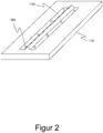
- FIG. 10 shows a perspective illustration of the component 100 in which a second component 120 has been fixed to the first component 110.
- the induction device 140 was used in each of the discrete subregions 160 Figure 1 the adhesive layer between the first component 110 and the second component 120 is tempered, so that in this area the adhesive layer has a higher surface adhesion in order to fix the second component 120 to the first component 110.
Landscapes
- Engineering & Computer Science (AREA)
- Mechanical Engineering (AREA)
- Chemical & Material Sciences (AREA)
- Combustion & Propulsion (AREA)
- Chemical Kinetics & Catalysis (AREA)
- General Chemical & Material Sciences (AREA)
- Physics & Mathematics (AREA)
- Thermal Sciences (AREA)
- Laminated Bodies (AREA)
Description
- Die Erfindung betrifft ein Verfahren zur Herstellung eines Bauteils aus wenigstens zwei miteinander zu verklebenden Bauelementen.
- Der Einsatz von Faserverbundwerkstoffen in der Luft- und Raumfahrt sowie in der Automobilindustrie hat sich aufgrund der vorteilhaften Eigenschaft dieser Werkstoffe etabliert. Dennoch sind derartige Faserverbundwerkstoffe nicht frei von Nachteilen. Mit dem Einsatz von Faserverbundhybridwerkstoffen, die neben einem Fasermaterial noch ein weiteres, faserfremdes Material, wie bspw. Metall, aufweisen, können die vorteilhaften Eigenschaften von Faserverbundwerkstoffen mit den vorteilhaften Eigenschaften von isotropen Werkstoffen kombiniert werden, um so die Nachteile jedes einzelnen Werkstoffes unter Umständen ausgleichen zu können.
- Ein Faserverbundhybridwerkstoff ist dabei ein Werkstoff, der aus sich abwechselnden Faser- und Metallschichten gebildet wird, wobei die Faserschichten ein Fasermaterial und ein Matrixmaterial aufweisen. Die Fasermaterialien können dabei herkömmliche Fasermaterialien zur Herstellung eines Faserverbundbauteils sein, wie bspw. Glasfasermaterialien oder Kohlenstofffasermaterialien.
- Einer der bekanntesten Vertreter von Faserverbundhybridwerkstoffen ist ein glasfaserverstärkter Aluminiumwerkstoff (GLARE), bei dem sich Schichten aus einem Faserverbundwerkstoff und einem Aluminiumwerkstoff abwechseln. Derartige glasfaserverstärkte Aluminiumwerkstoffe werden dabei mittlerweile in der kommerziellen Luftfahrt eingesetzt. Vor allem das verbesserte Einschlag- und Rissverhalten macht den Materialmix dieser Faserverbundhybridwerkstoffe besonders attraktiv für den Bau von Flugzeugrümpfen. Für eine ausreichende Steifigkeit des Rumpfes wird dieser durch die Integration von Versteifungselementen (sogenannten Stringern) verstärkt, wobei die Stringer durch Kleben in Integralbauweise mit dem sogenannten Hautfeld in Verbindung gebracht werden.
- Hierfür ist ein mehrstufiger Autoklavprozess notwendig, bei dem zuerst das Hautfeld ausgehärtet und anschließend die Stringer integriert, fixiert und vollständig verklebt werden. Für jeden Schritt ist dabei ein neuer Vakuumaufbau erforderlich, der sehr zeit- und kostenintensiv ist. In der Praxis erfolgt dabei die Integration der Stringer an das Hautfeld über Positionierhilfen in Form von Stiften, die in dem Hautfeld angeordnet und integriert sind. Diese werden nach dem mehrstufigen Autoklavprozess wieder entfernt, was einen weiteren Prozessschritt notwendig macht.
- Die Vorbereitung für die Positionierung der Versteifungselemente sowie der mehrstufige Autoklavprozess haben lange Prozesszeiten zur Folge. Besonders die Positionierstifte und -bohrungen gestalten den Prozess sehr aufwendig und komplex, da die Stifte bei der Schalenfertigung integriert werden müssen, im Nachhinein wieder entfernt werden müssen und die Stringer mit Positionierungsbohrungen versehen werden müssen. Die Stifte bilden vor allem für den Vakuumaufbau ein hohes Risiko, da die spitzen Stifte Gefahr laufen, die Vakuumfolie zu beschädigen.
- Aus der
DE 10 2011 112 520 A1 ist ein Verfahren zur Herstellung eines Faserverbundbauteils bekannt, bei dem zwei Faserverbund-Bauelemente mittels Klebung aneinander gefügt werden sollen. Mit Hilfe einer induktiven Erwärmung wird dabei der Klebwerkstoff erwärmt, um die beiden Faserverbund-Bauelemente aneinander zu fixieren. - Aus der
DE 11 2007 000 526 B4 ist ein Verfahren zum Befestigen einer Mutter an einem ein lochaufweisenden Werkstück bekannt, wobei zwischen der Mutter und dem Werkstoff eine Klebverbindung ausgebildet wird. - Aus der
DE 10 2012 112 313 A1 ist eine Kraftfahrzeugkarosserie bekannt, bei der Profile aus faserverstärktem Kunststoff mit Leichtmetallknoten verklebt werden. - Aus der
WO 2009/047010 A2 ist ein Verfahren zum Verbinden zweier Materialien mittels einer Klebverbindung bekannt, wobei der Klebschicht ein induktiv erwärmbares metallisches Material hinzugefügt wird, welches dann mit Hilfe einer Induktionsvorrichtung erwärmt wird, um so den Klebwerkstoff der Klebschicht thermisch zu aktivieren und ihn auf diese Weise auszuhärten. - Es ist Aufgabe der vorliegenden Erfindung, ein verbessertes Verfahren zur Herstellung eines Bauteils aus wenigstens zwei miteinander zu verklebenden Bauelementen anzugeben, bei dem mindestens ein Bauelement aus einem Faserverbundhybridwerkstoff hergestellt wird.
- Die Aufgabe wird mit dem Verfahren gemäß Anspruch 1 erfindungsgemäß gelöst.
- Gemäß Anspruch 1 wird ein Verfahren zur Herstellung eines Bauteils aus wenigstens zwei miteinander zu verklebenden Bauelementen vorgeschlagen, wobei gemäß dem Verfahren ein erstes Bauelement aus einem Faserverbundhybridwerkstoff bereitgestellt wird. Der Faserverbundhybridwerkstoff ist dabei aus sich abwechselnden Faser- und Metallschichten gebildet, wobei die Faserschichten ein Fasermaterial und ein Matrixmaterial eines Faserverbundwerkstoffes aufweisen. Hierbei kann es sich insbesondere um elektrisch nicht leitendes Fasermaterial handeln.
- Des Weiteren wird wenigstens ein zweites Bauelement bereitgestellt, das mit dem ersten Bauelement mittels einer nicht ausgehärteten Klebschicht zwischen den Bauelementen angeordnet ist oder wird.
- So ist es in einer ersten Alternative vorgesehen, dass das erste und das wenigstens zweite Bauelement getrennt voneinander bereitgestellt werden, wobei dann in einem Zwischenschritt das zweite Bauelement mittels einer nicht ausgehärteten Klebschicht an dem ersten Bauelement angeordnet wird, indem das zweite Bauelement an das erste Bauelement gefügt wird und zwischen dem ersten und zweiten Bauelement die nicht ausgehärtete Klebschicht vorgesehen ist. In einer zweiten Alternative werden das erste Bauelement und das zweite Bauelement wie eine bereits gefügte Form bereitgestellt, bei der das zweite Bauelement mittels der nicht ausgehärteten Klebschicht bereits an dem ersten Bauelement angeordnet ist.
- Anschließend wird in einem ersten Temperierschritt bzw. Temperierprozess die nicht ausgehärtete Klebschicht in wenigstens einem Teilbereich, vorzugsweise in mehreren lokal begrenzten Teilbereichen temperiert (Vortemperierung), indem eine oder mehrere Metallschichten des Faserverbundhybridwerkstoffs des ersten Bauelementes in diesen vorgegebenen Teilbereichen temperiert wird. Die Temperierung der einen oder mehreren Metallschichten erfolgt dabei derart, dass die Klebschicht wenigstens in den vorgegebenen Teilbereichen eine höhere Flächenhaftung als die nicht ausgehärtete Klebschicht vor der Temperierung erhält, ohne dabei vollständig auszuhärten. Nur so ist es möglich, dass durch eine erhöhte Flächenhaftung das zweite Bauelement an dem ersten Bauelement fixiert wird. Dabei darf der Klebstoff der Klebschicht jedoch nicht vollständig aushärten, da zu diesem Zeitpunkt das Matrixmaterial des Faserverbundhybridwerkstoffes ebenfalls noch nicht ausgehärtet ist und sowohl die Klebstoffschicht als auch das Matrixmaterial des Faserverbundhybridwerkstoffes in einem Prozessschritt gleichzeitig ausgehärtet werden sollen (sogenanntes Co-bonding).
- Nach dem ersten Temperierprozess (Vortemperierung) werden dann die so fixierten Bauelemente in einen Ofen eingefahren und in einem zweiten Temperierprozess bzw. Temperierschritt temperiert, sodass sowohl die Klebschicht als auch das Matrixmaterial des Faserverbundhybridwerkstoffes des ersten Bauelementes vollständig während dieses zweiten Temperierprozesses aushärten. Die hierfür notwendige Temperatur, mit der das Matrixmaterial und die Klebschicht in dem zweiten Temperierprozess beaufschlagt werden, ist dabei wesentlich höher als die Temperatur des ersten Temperierschrittes, bei dem in Teilbereichen die Klebschicht temperiert wird.
- Mit Hilfe dieses Verfahrens wird es erstmals möglich, insbesondere bei der Herstellung von Flugzeugstrukturen mit Versteifungselementen auf die Fixierstifte zum Fixieren der Versteifungselemente auf dem Hautfeld zu verzichten, da während des Fügens der Versteifungselemente (zweite Bauelemente) auf dem Hautfeld (erstes Bauelement) eine Vorfixierung der Versteifungselemente stattfindet, ohne hierbei das Bauteil in Teilbereichen aushärten zu müssen. Vielmehr kann das gesamte Bauteil dann zusammen in einem einzigen Prozessschritt vollständig ausgehärtet werden, sodass es lediglich eines einzigen Vakuumaufbaus bedarf. Die aus dem Stand der Technik bekannten Nachteile des in der Praxis durchgeführten Herstellungsprozesses entfallen somit.
- Dabei haben die Erfinder erkannt, dass durch eine Temperierung der Metallschicht des Faserverbundhybridwerkstoffes eine Temperierung der Klebschicht zwischen dem ersten und dem zweiten Bauelement derart bewirkt werden kann, dass die Flächenhaftung der Klebschicht gegenüber der nicht temperierten Klebschicht erhöht werden kann, um so die Bauelemente aneinander zu fixieren. Eine solche Temperierung einer oder mehrerer Metallschichten des Faserverbundhybridwerkstoffes kann dabei bspw. durch ein Bestromen der Metallschichten in Art einer Widerstandsheizung erfolgen. In einer vorteilhaften Ausführungsform, wie später noch gezeigt, kann dies auch durch induktive Erwärmung realisiert werden.
- In einer vorteilhaften Ausführungsform ist der Faserverbundhybridwerkstoff des ersten Bauelementes ein faserverstärkter Aluminiumwerkstoff, insbesondere ein glasfaserverstärkter Aluminiumwerkstoff (auch bezeichnet als GLARE), wie er vermehrt auch in der Luftfahrtindustrie eingesetzt wird. Dabei kann das zweite Bauelement ebenfalls einen solchen Faserverbundhybridwerkstoff aufweisen oder aus einem solchen bestehen oder nur aus einem reinen Metallwerkstoff, bspw. Aluminium.
- In einer weiteren vorteilhaften Ausführungsform weist die Klebstoffschicht ein Matrixmaterial als Klebstoff auf, sodass die Klebstoffschicht basierend auf den gleichen Randparametern in dem Ofen in dem zweiten Temperierprozessschritt mit ausgehärtet werden kann. Vorteilhafterweise handelt es sich bei der Klebschicht um ein Matrixmaterial, wie es auch bei dem Faserverbundhybridwerkstoff eingesetzt ist. Hierdurch kann sowohl das Matrixmaterial des Faserverbundhybridwerkstoffes als auch das Matrixmaterial der Klebschicht zwischen dem ersten und dem zweiten Bauelement unter denselben Prozessparametern ausgehärtet werden.
- In einer vorteilhaften Ausführungsform werden die Metallschichten des Faserverbundhybridwerkstoffes des ersten Bauelementes in dem ersten Temperierprozessschritt derart temperiert, dass die Klebschicht in dem wenigstens einen Teilbereich auf eine Temperatur zwischen 40° bis 70°C, vorzugsweise zwischen 45° bis 55°C, erwärmt wird. Gerade in diesen Temperaturbereichen erhält ein Matrixmaterial als Klebschicht eine verbesserte Flächenhaftung derart, dass die Bauelemente aneinander fixiert werden können, ohne dass die Klebschicht dabei vollständig ausgehärtet wird. Vielmehr erhöht sich in diesen Temperaturbereichen die Klebrigkeit der Klebschicht, sodass das Bauteil in einen Ofen eingefahren werden kann, ohne dass befürchtet werden muss, dass das zweite Bauelement gegenüber dem ersten Bauelement verrutscht. Nicht vollständig ausgehärtet bedeutet insbesondere einen Aushärtezustand oder Polymerisationszustand oder Vernetzungszustand von weniger als 80 %, vorzugsweise weniger als 50 %, besonders vorzugsweise weniger als 30 %.
- In einer weiteren vorteilhaften Ausführungsform wird ein elektromagnetisches Wechselfeld in das erste Bauelement in dem wenigstens einen Teilbereich zur induktiven Temperierung einer oder mehrerer Metallschichten des Faserverbundhybridwerkstoffes des ersten Bauelementes eingestrahlt, wodurch es zu einer Wechselwirkung mit den Metallschichten des Faserverbundhybridwerkstoffes kommt, derart, dass Wirbelströme in den Metallschichten erzeugt und die Metallschichten in diesen Bereichen, in denen das elektromagnetische Wechselfeld in Dickenrichtung eingestrahlt wird, erwärmt werden. Durch die Erwärmung der Metallschichten in diesen Bereichen wird schließlich auch die Klebschicht zwischen dem ersten und dem zweiten Bauelement erwärmt, wodurch die erhöhte Flächenhaftung zum Fixieren des zweiten Bauelementes realisiert wird.
- So haben die Erfinder erkannt, dass bei der Verwendung eines glasfaserverstärkten Aluminiumwerkstoffes (GLARE) und einer Induktionsvorrichtung zum Einstrahlen eines elektromagnetischen Wechselfeldes, das eine Leistung von ca. 400 Watt hat, weniger als 5 Sekunden benötigt werden, um die Klebschicht in dem vorgegebenen Teilbereich des Bauteils auf ca. 50°C zu erwärmen, um die beiden Bauelemente aneinander zu fixieren. Es ist daher besonders vorteilhaft, wenn die Einstrahlung des elektromagnetischen Wechselfeldes weniger als 10 Sekunden, vorzugsweise weniger als 5 Sekunden pro Teilbereich erfolgt.
- In einer vorteilhaften Ausführungsform wird eine Induktionsvorrichtung bereitgestellt, die einen Induktionsgenerator, eine Induktionsspule sowie einen Konzentrator aufweist, wobei das Einstrahlen des elektromagnetischen Wechselfeldes mit der bereitgestellten Induktionsvorrichtungerfolgt.
- Die Erfindung wird anhand der beigefügten Figuren beispielhaft näher erläutert. Es zeigen:
- Figur 1
- schematische Darstellung des erfindungsgemäßen Verfahrens in einer Querschnittdarstellung;
- Figur 2
- schematische, perspektivische Darstellung des Bauteils.
-
Figur 1 zeigt in einer Querschnittdarstellung ein Bauteil 100, das aus einem ersten Bauelement 110 und einem zweiten Bauelement 120 hergestellt wird. Das erste Bauelement 110 weist dabei einen Faserverbundhybridwerkstoff auf, bei dem sich Faserschichten 112 und Metallschichten 114 abwechseln. An einer Außenseite 116 des ersten Bauelementes 110 wird eine Klebschicht 130 aufgebracht und dann das zweite Bauelement 120 auf das erste Bauelement 110 gefügt. Bei der Klebschicht 130 kann es sich um ein Matrixmaterial handeln, wie es in der Faserschicht 112 des ersten Bauelementes 110 vorgesehen ist. - Bei dem zweiten Bauelement 120 kann es sich bspw. um ein Aluminiumbauteil handeln. Das in
Figur 1 abgebildete Bauteil ist eine Flügelschale mit einem Verstärkungselement, wobei das Hautfeld das erste Bauelement 110 darstellt, während das Versteifungselement durch das zweite Bauelement 120 gebildet wird. - Mit Hilfe einer Induktionsvorrichtung 140 wird nun an diskreten Teilbereichen des Bauelementes 110 die Klebschicht 130 derart temperiert, dass sich die Flächenhaftung der Klebschicht 130 in diesem Bereich gegenüber den anderen, nicht temperierten Bereichen erhöht, sodass das zweite Bauelement 120 mit Hilfe dieser Klebschicht 130 zunächst an dem ersten Bauelement fixiert, aber nach wie vor lösbar angeordnet ist.
- Anschließend kann das Bauteil 100 in einen Autoklaven 150 eingefahren werden, ohne dass die Gefahr zu befürchten ist, dass das zweite Bauelement 120 gegenüber dem ersten Bauelement 110 verrutscht.
- Die Induktionsvorrichtung 140 weist einen Induktionsgenerator 142 auf, der ein Schwingkreis-Induktionsgenerator mit einem Oszillator, der auf der insulated-gate bipolar transistor (IGBT) Technik beruhen kann, auf. Der Induktionsgenerator 142 regt dabei eine Induktionsspule 144 mit einer Wechselspannung an, wobei die Induktionsspule durch ein Gehäuse oder einen Einguss elektrisch isoliert und gegebenenfalls aktiv gekühlt ist. Aufgrund der hohen Leistung sollte die Spule relativ große Abmessungen haben, um nicht zu überhitzen. Die zu verklebenden Versteifungselemente haben sehr kleine Abmessungen. Daher ist ein Konzentrator 146 vorteilhaft, der die magnetischen Feldlinien auf den zu erwärmenden Bereich konzentriert. Die Verwendung des Konzentrators 146 ist eine Sache der Auslegung und stellt hier nur ein Beispiel dar.
-
Figur 2 zeigt in einer perspektivischen Darstellung das Bauteil 100, bei dem ein zweites Bauelement 120 an dem ersten Bauelement 110 fixiert wurde. Hierfür wurde an diskreten Teilbereichen 160 jeweils mit Hilfe der Induktionsvorrichtung 140 ausFigur 1 die Klebschicht zwischen dem ersten Bauelement 110 und dem zweiten Bauelement 120 temperiert, sodass in diesem Bereich die Klebschicht eine höhere Flächenhaftung erhalten hat, um so das zweite Bauelement 120 an dem ersten Bauelement 110 zu fixieren. -
- 100
- Bauteil
- 110
- erstes Bauelement
- 112
- Faserschicht
- 114
- Metallschicht
- 116
- Außenseite
- 120
- zweites Bauelement
- 130
- Klebschicht
- 140
- Induktionsvorrichtung
- 142
- Induktionsgenerator
- 144
- Induktionsspule
- 146
- Konzentrator
- 150
- Autoklav/Ofen
- 160
- Teilbereich
Claims (6)
- Verfahren zur Herstellung eines Bauteils (100) aus wenigstens zwei miteinander zu verklebenden Bauelementen (110, 120), mit den Schritten:- Bereitstellen eines ersten Bauelementes (110) aus einem Faserverbundhybridwerkstoff, der aus sich abwechselnden Faser- und Metallschichten (112, 114) gebildet ist und bei dem die Faserschichten (112) ein Fasermaterial und ein Matrixmaterial eines Faserverbundwerkstoffes aufweisen,- Bereitstellen wenigstens eines zweiten Bauelementes (120), das an dem ersten Bauelement (110) mittels einer nicht ausgehärteten Klebschicht (130) zwischen den Bauelementen (110, 120) angeordnet ist oder wird, gekennzeichnet durch- Temperieren der nicht ausgehärteten Klebschicht (130) in wenigstens einem Teilbereich (160), indem eine oder mehrere Metallschichten (114) des Faserverbundhybridwerkstoffes des ersten Bauelementes (110) in zumindest diesem Teilbereich (160) temperiert wird, derart, dass die Klebschicht (130) in diesem Teilbereich (160) eine höhere Flächenhaftung als die nicht ausgehärtete Klebschicht (130) erhält, ohne dabei vollständig auszuhärten, um so das zweite Bauelement (120) an dem ersten Bauelement (110) zu fixieren, und- Einfahren der fixierten Bauelemente (110, 120) in einen Ofen (150) und Temperieren der fixierten Bauelemente (110, 120) zum vollständigen Aushärten der Klebschicht (130) zwischen dem ersten Bauelement (110) und dem zweiten Bauelement (120).
- Verfahren nach Anspruch 1, dadurch gekennzeichnet, dass der Faserverbundhybridwerkstoff des ersten Bauelementes (110) ein faserverstärkter Aluminiumwerkstoff, insbesondere ein glasfaserverstärkter Aluminiumwerkstoff, ist.
- Verfahren nach Anspruch 1 oder 2, dadurch gekennzeichnet, dass die eine oder mehreren Metallschichten (114) des Faserverbundhybridwerkstoffes des ersten Bauelementes (110) derart temperiert werden, dass die Klebschicht (130) in dem wenigstens einen Teilbereich (160) auf eine Temperatur zwischen 40° bis 70°C, vorzugsweise zwischen 45° bis 55°C, temperiert wird.
- Verfahren nach einem der vorhergehenden Ansprüche, dadurch gekennzeichnet, dass ein elektromagnetisches Wechselfeld in das erste Bauelement (110) in dem wenigstens einen Teilbereich (160) zur induktiven Temperierung einer oder mehrerer Metallschichten (114) des Faserverbundhybridwerkstoffes des ersten Bauelementes (110) eingestrahlt wird.
- Verfahren nach Anspruch 4, dadurch gekennzeichnet, dass eine Induktionsvorrichtung (140) bereitgestellt wird, die einen Induktionsgenerator (142), eine Induktionsspule (144) sowie einen Konzentrator (146) aufweist, wobei das Einstrahlen des elektromagnetischen Wechselfeldes mittels der bereitgestellten Induktionsvorrichtung (140) erfolgt.
- Verfahren nach einem der vorhergehenden Ansprüche, dadurch gekennzeichnet, dass das herzustellende Bauteil (100) ein Flugzeugbauteil ist, bei dem das erste Bauelement (110) eine flächige Flugzeugstruktur ist, an dem eine Mehrzahl von Versteifungselementen als zweite Bauelemente (120) angeordnet und verklebt werden.
Applications Claiming Priority (1)
| Application Number | Priority Date | Filing Date | Title |
|---|---|---|---|
| DE102017101897.2A DE102017101897B4 (de) | 2017-01-31 | 2017-01-31 | Verfahren zur Herstellung eines Bauteils |
Publications (2)
| Publication Number | Publication Date |
|---|---|
| EP3354444A1 EP3354444A1 (de) | 2018-08-01 |
| EP3354444B1 true EP3354444B1 (de) | 2021-04-28 |
Family
ID=61132050
Family Applications (1)
| Application Number | Title | Priority Date | Filing Date |
|---|---|---|---|
| EP18154236.6A Active EP3354444B1 (de) | 2017-01-31 | 2018-01-30 | Verfahren zur herstellung eines bauteils |
Country Status (3)
| Country | Link |
|---|---|
| EP (1) | EP3354444B1 (de) |
| DE (1) | DE102017101897B4 (de) |
| ES (1) | ES2878086T3 (de) |
Families Citing this family (1)
| Publication number | Priority date | Publication date | Assignee | Title |
|---|---|---|---|---|
| EP3835036A1 (de) * | 2019-12-13 | 2021-06-16 | Sika Technology Ag | Vorfixierung zweier substrate |
Family Cites Families (4)
| Publication number | Priority date | Publication date | Assignee | Title |
|---|---|---|---|---|
| US7527463B2 (en) | 2006-03-10 | 2009-05-05 | Gm Global Technology Operations, Inc. | Nut and method for adhesive nut attachment |
| DE102007000862A1 (de) * | 2007-10-12 | 2009-04-23 | Airbus Deutschland Gmbh | Verfahren zum Verbinden eines ersten Materials mit einem zweiten Material im Flugzeug |
| DE102011112520A1 (de) | 2011-09-07 | 2013-03-07 | Deutsches Zentrum für Luft- und Raumfahrt e.V. | Herstellung eines Faserverbundbauelementes |
| DE102012112313A1 (de) | 2012-12-14 | 2014-06-18 | Dr. Ing. H.C. F. Porsche Aktiengesellschaft | Kraftfahrzeugkarosserie |
-
2017
- 2017-01-31 DE DE102017101897.2A patent/DE102017101897B4/de not_active Expired - Fee Related
-
2018
- 2018-01-30 EP EP18154236.6A patent/EP3354444B1/de active Active
- 2018-01-30 ES ES18154236T patent/ES2878086T3/es active Active
Non-Patent Citations (1)
| Title |
|---|
| None * |
Also Published As
| Publication number | Publication date |
|---|---|
| DE102017101897B4 (de) | 2020-11-19 |
| EP3354444A1 (de) | 2018-08-01 |
| ES2878086T3 (es) | 2021-11-18 |
| DE102017101897A1 (de) | 2018-08-02 |
Similar Documents
| Publication | Publication Date | Title |
|---|---|---|
| EP2274158B1 (de) | Verfahren und Umformvorrichtung zur Herstellung eines Faserverbundbauteils für die Luft- und Raumfahrt | |
| DE102006007429B4 (de) | Verfahren zum autoklavfreien Verkleben von Bauteilen für Luftfahrzeuge | |
| DE102008010197A1 (de) | Verfahren zum Verbinden von zwei Rumpfsektionen unter Schaffung eines Querstoßes sowie Querstoßverbindung | |
| EP2254788A2 (de) | Verfahren zur herstellung eines fvw-bauteils, fvw-bauteil sowie ein fvw-rumpfteil eines flugzeugs | |
| DE102007033261A1 (de) | Faserverbundbauteil mit thermoplastischen Versteifungselementen | |
| DE102011006792B4 (de) | Verfahren zum Herstellen und Verbinden von faserverstärkten Bauteilen sowie Luft- oder Raumfahrzeug | |
| DE102016123456A1 (de) | Verbundwerkzeuge zum bearbeiten von luftfahrzeugen und verfahren verwendend gelenkdorne | |
| DE102013114574B4 (de) | Trennfolie sowie Verfahren | |
| DE102017101897B4 (de) | Verfahren zur Herstellung eines Bauteils | |
| DE102013107105B4 (de) | Faservorformling-Temperiervorrichtung | |
| DE102023101310B4 (de) | Verfahren zur Herstellung eines Hybridbauteils | |
| EP2567805B1 (de) | Herstellung eines Faserverbundbauelementes | |
| DE102012207359A1 (de) | Verfahren zum Wiederverwerten von Verbundbauteilen sowie Trennanordnung | |
| WO2005032793A1 (de) | Verfahren zur herstellung eines verbundbauteils sowie hiermit hergestelltes verbundbauteil | |
| DE102016207354A1 (de) | Verfahren zur Herstellung eines Strukturbauteils für ein Kraftfahrzeug | |
| DE102014226148A1 (de) | Kleben von Klebebolzen | |
| DE102016206517A1 (de) | Verfahren zur Herstellung eines mehrschichtigen Kunststoffbauteils | |
| WO2019115041A1 (de) | Faserverstärkte fahrzeugkarosserie | |
| DE102017219980A1 (de) | Verfahren zur Herstellung einer faserverstärkten Fahrzeugkarosserie | |
| DE102007004313B4 (de) | Verfahren zur Herstellung eines Bauteils für ein Luft- oder Raumfahrzeug | |
| DE102018109488B4 (de) | Verfahren zum klebenden Fügen eines ersten und zweiten Fügepartners | |
| DE102021110631A1 (de) | Fluggerätgrundkörper | |
| DE102019132719A1 (de) | Verfahren und Vorrichtung zum Herstellen eines Duroplast-Thermoplast-Verbunds und Duroplast-Thermoplast-Verbund-Bauteil | |
| WO2023025460A1 (de) | Kunststoffbauteil für ein Kraftfahrzeug, Bauteilverbund für ein Kraftfahrzeug, Verfahren zur Herstellung eines Kunststoffbauteils für ein Kraftfahrzeug und Verfahren zur Herstellung eines Bauteilverbundes für ein Kraftfahrzeug | |
| DE102023125377A1 (de) | Verfahren zur Herstellung eines zusammengesetzten Faserverbundbauteils aus mehreren einzelnen Bauelementen |
Legal Events
| Date | Code | Title | Description |
|---|---|---|---|
| PUAI | Public reference made under article 153(3) epc to a published international application that has entered the european phase |
Free format text: ORIGINAL CODE: 0009012 |
|
| STAA | Information on the status of an ep patent application or granted ep patent |
Free format text: STATUS: THE APPLICATION HAS BEEN PUBLISHED |
|
| AK | Designated contracting states |
Kind code of ref document: A1 Designated state(s): AL AT BE BG CH CY CZ DE DK EE ES FI FR GB GR HR HU IE IS IT LI LT LU LV MC MK MT NL NO PL PT RO RS SE SI SK SM TR |
|
| AX | Request for extension of the european patent |
Extension state: BA ME |
|
| STAA | Information on the status of an ep patent application or granted ep patent |
Free format text: STATUS: REQUEST FOR EXAMINATION WAS MADE |
|
| 17P | Request for examination filed |
Effective date: 20190131 |
|
| RBV | Designated contracting states (corrected) |
Designated state(s): AL AT BE BG CH CY CZ DE DK EE ES FI FR GB GR HR HU IE IS IT LI LT LU LV MC MK MT NL NO PL PT RO RS SE SI SK SM TR |
|
| STAA | Information on the status of an ep patent application or granted ep patent |
Free format text: STATUS: EXAMINATION IS IN PROGRESS |
|
| 17Q | First examination report despatched |
Effective date: 20200710 |
|
| GRAP | Despatch of communication of intention to grant a patent |
Free format text: ORIGINAL CODE: EPIDOSNIGR1 |
|
| STAA | Information on the status of an ep patent application or granted ep patent |
Free format text: STATUS: GRANT OF PATENT IS INTENDED |
|
| RIC1 | Information provided on ipc code assigned before grant |
Ipc: B29C 65/78 20060101ALI20201027BHEP Ipc: B29C 65/36 20060101ALI20201027BHEP Ipc: B29C 65/48 20060101AFI20201027BHEP Ipc: B29C 65/10 20060101ALI20201027BHEP Ipc: B29L 31/30 20060101ALN20201027BHEP |
|
| INTG | Intention to grant announced |
Effective date: 20201117 |
|
| GRAS | Grant fee paid |
Free format text: ORIGINAL CODE: EPIDOSNIGR3 |
|
| GRAA | (expected) grant |
Free format text: ORIGINAL CODE: 0009210 |
|
| STAA | Information on the status of an ep patent application or granted ep patent |
Free format text: STATUS: THE PATENT HAS BEEN GRANTED |
|
| AK | Designated contracting states |
Kind code of ref document: B1 Designated state(s): AL AT BE BG CH CY CZ DE DK EE ES FI FR GB GR HR HU IE IS IT LI LT LU LV MC MK MT NL NO PL PT RO RS SE SI SK SM TR |
|
| REG | Reference to a national code |
Ref country code: GB Ref legal event code: FG4D Free format text: NOT ENGLISH |
|
| REG | Reference to a national code |
Ref country code: CH Ref legal event code: EP |
|
| REG | Reference to a national code |
Ref country code: AT Ref legal event code: REF Ref document number: 1386625 Country of ref document: AT Kind code of ref document: T Effective date: 20210515 |
|
| REG | Reference to a national code |
Ref country code: DE Ref legal event code: R096 Ref document number: 502018004958 Country of ref document: DE |
|
| REG | Reference to a national code |
Ref country code: IE Ref legal event code: FG4D Free format text: LANGUAGE OF EP DOCUMENT: GERMAN |
|
| REG | Reference to a national code |
Ref country code: NL Ref legal event code: FP |
|
| REG | Reference to a national code |
Ref country code: LT Ref legal event code: MG9D |
|
| PG25 | Lapsed in a contracting state [announced via postgrant information from national office to epo] |
Ref country code: FI Free format text: LAPSE BECAUSE OF FAILURE TO SUBMIT A TRANSLATION OF THE DESCRIPTION OR TO PAY THE FEE WITHIN THE PRESCRIBED TIME-LIMIT Effective date: 20210428 Ref country code: LT Free format text: LAPSE BECAUSE OF FAILURE TO SUBMIT A TRANSLATION OF THE DESCRIPTION OR TO PAY THE FEE WITHIN THE PRESCRIBED TIME-LIMIT Effective date: 20210428 Ref country code: HR Free format text: LAPSE BECAUSE OF FAILURE TO SUBMIT A TRANSLATION OF THE DESCRIPTION OR TO PAY THE FEE WITHIN THE PRESCRIBED TIME-LIMIT Effective date: 20210428 Ref country code: BG Free format text: LAPSE BECAUSE OF FAILURE TO SUBMIT A TRANSLATION OF THE DESCRIPTION OR TO PAY THE FEE WITHIN THE PRESCRIBED TIME-LIMIT Effective date: 20210728 |
|
| REG | Reference to a national code |
Ref country code: ES Ref legal event code: FG2A Ref document number: 2878086 Country of ref document: ES Kind code of ref document: T3 Effective date: 20211118 |
|
| PG25 | Lapsed in a contracting state [announced via postgrant information from national office to epo] |
Ref country code: LV Free format text: LAPSE BECAUSE OF FAILURE TO SUBMIT A TRANSLATION OF THE DESCRIPTION OR TO PAY THE FEE WITHIN THE PRESCRIBED TIME-LIMIT Effective date: 20210428 Ref country code: PT Free format text: LAPSE BECAUSE OF FAILURE TO SUBMIT A TRANSLATION OF THE DESCRIPTION OR TO PAY THE FEE WITHIN THE PRESCRIBED TIME-LIMIT Effective date: 20210830 Ref country code: PL Free format text: LAPSE BECAUSE OF FAILURE TO SUBMIT A TRANSLATION OF THE DESCRIPTION OR TO PAY THE FEE WITHIN THE PRESCRIBED TIME-LIMIT Effective date: 20210428 Ref country code: NO Free format text: LAPSE BECAUSE OF FAILURE TO SUBMIT A TRANSLATION OF THE DESCRIPTION OR TO PAY THE FEE WITHIN THE PRESCRIBED TIME-LIMIT Effective date: 20210728 Ref country code: SE Free format text: LAPSE BECAUSE OF FAILURE TO SUBMIT A TRANSLATION OF THE DESCRIPTION OR TO PAY THE FEE WITHIN THE PRESCRIBED TIME-LIMIT Effective date: 20210428 Ref country code: RS Free format text: LAPSE BECAUSE OF FAILURE TO SUBMIT A TRANSLATION OF THE DESCRIPTION OR TO PAY THE FEE WITHIN THE PRESCRIBED TIME-LIMIT Effective date: 20210428 Ref country code: IS Free format text: LAPSE BECAUSE OF FAILURE TO SUBMIT A TRANSLATION OF THE DESCRIPTION OR TO PAY THE FEE WITHIN THE PRESCRIBED TIME-LIMIT Effective date: 20210828 Ref country code: GR Free format text: LAPSE BECAUSE OF FAILURE TO SUBMIT A TRANSLATION OF THE DESCRIPTION OR TO PAY THE FEE WITHIN THE PRESCRIBED TIME-LIMIT Effective date: 20210729 |
|
| PG25 | Lapsed in a contracting state [announced via postgrant information from national office to epo] |
Ref country code: RO Free format text: LAPSE BECAUSE OF FAILURE TO SUBMIT A TRANSLATION OF THE DESCRIPTION OR TO PAY THE FEE WITHIN THE PRESCRIBED TIME-LIMIT Effective date: 20210428 Ref country code: CZ Free format text: LAPSE BECAUSE OF FAILURE TO SUBMIT A TRANSLATION OF THE DESCRIPTION OR TO PAY THE FEE WITHIN THE PRESCRIBED TIME-LIMIT Effective date: 20210428 Ref country code: DK Free format text: LAPSE BECAUSE OF FAILURE TO SUBMIT A TRANSLATION OF THE DESCRIPTION OR TO PAY THE FEE WITHIN THE PRESCRIBED TIME-LIMIT Effective date: 20210428 Ref country code: SK Free format text: LAPSE BECAUSE OF FAILURE TO SUBMIT A TRANSLATION OF THE DESCRIPTION OR TO PAY THE FEE WITHIN THE PRESCRIBED TIME-LIMIT Effective date: 20210428 Ref country code: SM Free format text: LAPSE BECAUSE OF FAILURE TO SUBMIT A TRANSLATION OF THE DESCRIPTION OR TO PAY THE FEE WITHIN THE PRESCRIBED TIME-LIMIT Effective date: 20210428 Ref country code: EE Free format text: LAPSE BECAUSE OF FAILURE TO SUBMIT A TRANSLATION OF THE DESCRIPTION OR TO PAY THE FEE WITHIN THE PRESCRIBED TIME-LIMIT Effective date: 20210428 |
|
| REG | Reference to a national code |
Ref country code: DE Ref legal event code: R097 Ref document number: 502018004958 Country of ref document: DE |
|
| PLBE | No opposition filed within time limit |
Free format text: ORIGINAL CODE: 0009261 |
|
| STAA | Information on the status of an ep patent application or granted ep patent |
Free format text: STATUS: NO OPPOSITION FILED WITHIN TIME LIMIT |
|
| 26N | No opposition filed |
Effective date: 20220131 |
|
| PG25 | Lapsed in a contracting state [announced via postgrant information from national office to epo] |
Ref country code: IS Free format text: LAPSE BECAUSE OF FAILURE TO SUBMIT A TRANSLATION OF THE DESCRIPTION OR TO PAY THE FEE WITHIN THE PRESCRIBED TIME-LIMIT Effective date: 20210828 Ref country code: AL Free format text: LAPSE BECAUSE OF FAILURE TO SUBMIT A TRANSLATION OF THE DESCRIPTION OR TO PAY THE FEE WITHIN THE PRESCRIBED TIME-LIMIT Effective date: 20210428 |
|
| PG25 | Lapsed in a contracting state [announced via postgrant information from national office to epo] |
Ref country code: IT Free format text: LAPSE BECAUSE OF FAILURE TO SUBMIT A TRANSLATION OF THE DESCRIPTION OR TO PAY THE FEE WITHIN THE PRESCRIBED TIME-LIMIT Effective date: 20210428 |
|
| PG25 | Lapsed in a contracting state [announced via postgrant information from national office to epo] |
Ref country code: MC Free format text: LAPSE BECAUSE OF FAILURE TO SUBMIT A TRANSLATION OF THE DESCRIPTION OR TO PAY THE FEE WITHIN THE PRESCRIBED TIME-LIMIT Effective date: 20210428 |
|
| REG | Reference to a national code |
Ref country code: CH Ref legal event code: PL |
|
| REG | Reference to a national code |
Ref country code: BE Ref legal event code: MM Effective date: 20220131 |
|
| PG25 | Lapsed in a contracting state [announced via postgrant information from national office to epo] |
Ref country code: LU Free format text: LAPSE BECAUSE OF NON-PAYMENT OF DUE FEES Effective date: 20220130 |
|
| PG25 | Lapsed in a contracting state [announced via postgrant information from national office to epo] |
Ref country code: BE Free format text: LAPSE BECAUSE OF NON-PAYMENT OF DUE FEES Effective date: 20220131 |
|
| PG25 | Lapsed in a contracting state [announced via postgrant information from national office to epo] |
Ref country code: LI Free format text: LAPSE BECAUSE OF NON-PAYMENT OF DUE FEES Effective date: 20220131 Ref country code: CH Free format text: LAPSE BECAUSE OF NON-PAYMENT OF DUE FEES Effective date: 20220131 |
|
| PG25 | Lapsed in a contracting state [announced via postgrant information from national office to epo] |
Ref country code: IE Free format text: LAPSE BECAUSE OF NON-PAYMENT OF DUE FEES Effective date: 20220130 |
|
| REG | Reference to a national code |
Ref country code: AT Ref legal event code: MM01 Ref document number: 1386625 Country of ref document: AT Kind code of ref document: T Effective date: 20230130 |
|
| PG25 | Lapsed in a contracting state [announced via postgrant information from national office to epo] |
Ref country code: HU Free format text: LAPSE BECAUSE OF FAILURE TO SUBMIT A TRANSLATION OF THE DESCRIPTION OR TO PAY THE FEE WITHIN THE PRESCRIBED TIME-LIMIT; INVALID AB INITIO Effective date: 20180130 |
|
| PG25 | Lapsed in a contracting state [announced via postgrant information from national office to epo] |
Ref country code: AT Free format text: LAPSE BECAUSE OF NON-PAYMENT OF DUE FEES Effective date: 20230130 |
|
| PG25 | Lapsed in a contracting state [announced via postgrant information from national office to epo] |
Ref country code: MK Free format text: LAPSE BECAUSE OF FAILURE TO SUBMIT A TRANSLATION OF THE DESCRIPTION OR TO PAY THE FEE WITHIN THE PRESCRIBED TIME-LIMIT Effective date: 20210428 Ref country code: CY Free format text: LAPSE BECAUSE OF FAILURE TO SUBMIT A TRANSLATION OF THE DESCRIPTION OR TO PAY THE FEE WITHIN THE PRESCRIBED TIME-LIMIT Effective date: 20210428 Ref country code: AT Free format text: LAPSE BECAUSE OF NON-PAYMENT OF DUE FEES Effective date: 20230130 |
|
| PG25 | Lapsed in a contracting state [announced via postgrant information from national office to epo] |
Ref country code: TR Free format text: LAPSE BECAUSE OF FAILURE TO SUBMIT A TRANSLATION OF THE DESCRIPTION OR TO PAY THE FEE WITHIN THE PRESCRIBED TIME-LIMIT Effective date: 20210428 |
|
| PG25 | Lapsed in a contracting state [announced via postgrant information from national office to epo] |
Ref country code: MT Free format text: LAPSE BECAUSE OF FAILURE TO SUBMIT A TRANSLATION OF THE DESCRIPTION OR TO PAY THE FEE WITHIN THE PRESCRIBED TIME-LIMIT Effective date: 20210428 |
|
| PGFP | Annual fee paid to national office [announced via postgrant information from national office to epo] |
Ref country code: GB Payment date: 20251211 Year of fee payment: 9 |
|
| PGFP | Annual fee paid to national office [announced via postgrant information from national office to epo] |
Ref country code: FR Payment date: 20251216 Year of fee payment: 9 Ref country code: NL Payment date: 20251219 Year of fee payment: 9 |
|
| PGFP | Annual fee paid to national office [announced via postgrant information from national office to epo] |
Ref country code: ES Payment date: 20260205 Year of fee payment: 9 |
|
| PGFP | Annual fee paid to national office [announced via postgrant information from national office to epo] |
Ref country code: DE Payment date: 20251222 Year of fee payment: 9 |
|
| PGFP | Annual fee paid to national office [announced via postgrant information from national office to epo] |
Ref country code: AT Payment date: 20260410 Year of fee payment: 5 |