EP3354410A1 - Electric tool - Google Patents
Electric tool Download PDFInfo
- Publication number
- EP3354410A1 EP3354410A1 EP18151754.1A EP18151754A EP3354410A1 EP 3354410 A1 EP3354410 A1 EP 3354410A1 EP 18151754 A EP18151754 A EP 18151754A EP 3354410 A1 EP3354410 A1 EP 3354410A1
- Authority
- EP
- European Patent Office
- Prior art keywords
- switch
- power supply
- circuit
- power
- winding
- Prior art date
- Legal status (The legal status is an assumption and is not a legal conclusion. Google has not performed a legal analysis and makes no representation as to the accuracy of the status listed.)
- Granted
Links
Images



Classifications
-
- H—ELECTRICITY
- H02—GENERATION; CONVERSION OR DISTRIBUTION OF ELECTRIC POWER
- H02P—CONTROL OR REGULATION OF ELECTRIC MOTORS, ELECTRIC GENERATORS OR DYNAMO-ELECTRIC CONVERTERS; CONTROLLING TRANSFORMERS, REACTORS OR CHOKE COILS
- H02P27/00—Arrangements or methods for the control of AC motors characterised by the kind of supply voltage
- H02P27/04—Arrangements or methods for the control of AC motors characterised by the kind of supply voltage using variable-frequency supply voltage, e.g. inverter or converter supply voltage
- H02P27/06—Arrangements or methods for the control of AC motors characterised by the kind of supply voltage using variable-frequency supply voltage, e.g. inverter or converter supply voltage using DC to AC converters or inverters
-
- B—PERFORMING OPERATIONS; TRANSPORTING
- B25—HAND TOOLS; PORTABLE POWER-DRIVEN TOOLS; MANIPULATORS
- B25F—COMBINATION OR MULTI-PURPOSE TOOLS NOT OTHERWISE PROVIDED FOR; DETAILS OR COMPONENTS OF PORTABLE POWER-DRIVEN TOOLS NOT PARTICULARLY RELATED TO THE OPERATIONS PERFORMED AND NOT OTHERWISE PROVIDED FOR
- B25F5/00—Details or components of portable power-driven tools not particularly related to the operations performed and not otherwise provided for
-
- B—PERFORMING OPERATIONS; TRANSPORTING
- B23—MACHINE TOOLS; METAL-WORKING NOT OTHERWISE PROVIDED FOR
- B23D—PLANING; SLOTTING; SHEARING; BROACHING; SAWING; FILING; SCRAPING; LIKE OPERATIONS FOR WORKING METAL BY REMOVING MATERIAL, NOT OTHERWISE PROVIDED FOR
- B23D47/00—Sawing machines or sawing devices working with circular saw blades, characterised only by constructional features of particular parts
- B23D47/12—Sawing machines or sawing devices working with circular saw blades, characterised only by constructional features of particular parts of drives for circular saw blades
-
- H—ELECTRICITY
- H02—GENERATION; CONVERSION OR DISTRIBUTION OF ELECTRIC POWER
- H02M—APPARATUS FOR CONVERSION BETWEEN AC AND AC, BETWEEN AC AND DC, OR BETWEEN DC AND DC, AND FOR USE WITH MAINS OR SIMILAR POWER SUPPLY SYSTEMS; CONVERSION OF DC OR AC INPUT POWER INTO SURGE OUTPUT POWER; CONTROL OR REGULATION THEREOF
- H02M1/00—Details of apparatus for conversion
- H02M1/10—Arrangements incorporating converting means for enabling loads to be operated at will from different kinds of power supplies, e.g. from AC or DC
-
- H—ELECTRICITY
- H02—GENERATION; CONVERSION OR DISTRIBUTION OF ELECTRIC POWER
- H02P—CONTROL OR REGULATION OF ELECTRIC MOTORS, ELECTRIC GENERATORS OR DYNAMO-ELECTRIC CONVERTERS; CONTROLLING TRANSFORMERS, REACTORS OR CHOKE COILS
- H02P4/00—Arrangements specially adapted for regulating or controlling the speed or torque of electric motors that can be connected to two or more different electric power supplies
-
- B—PERFORMING OPERATIONS; TRANSPORTING
- B23—MACHINE TOOLS; METAL-WORKING NOT OTHERWISE PROVIDED FOR
- B23D—PLANING; SLOTTING; SHEARING; BROACHING; SAWING; FILING; SCRAPING; LIKE OPERATIONS FOR WORKING METAL BY REMOVING MATERIAL, NOT OTHERWISE PROVIDED FOR
- B23D45/00—Sawing machines or sawing devices with circular saw blades or with friction saw discs
- B23D45/04—Sawing machines or sawing devices with circular saw blades or with friction saw discs with a circular saw blade or the stock carried by a pivoted lever
- B23D45/042—Sawing machines or sawing devices with circular saw blades or with friction saw discs with a circular saw blade or the stock carried by a pivoted lever with the saw blade carried by a pivoted lever
- B23D45/044—Sawing machines or sawing devices with circular saw blades or with friction saw discs with a circular saw blade or the stock carried by a pivoted lever with the saw blade carried by a pivoted lever the saw blade being adjustable according to angle of cut
Definitions
- the present disclosure relates to an electric tool, and particularly relates to an electric tool which can be connected to different power supplies.
- Existing electric tools include two categories. One category is powered by an alternating current power supply, and the other category is powered by a direct current power supply.
- the tools powered by the alternating current power supply generally only can be used in places closer to a socket of the power supply, and it is inconvenient to use the electric tools within a working range away from the socket of the power supply.
- the direct current power supply needs to be configured for supplying power, so that alternating current electric tools can be operated in places away from the socket of the power supply.
- a purpose of the present disclosure is to provide an electric tool which can be connected to different voltage inputs.
- An electric tool includes: a motor including a plurality of windings; a power circuit configured to selectively access a first power supply and a second power supply for supplying power for the motor and including an output anode and an output cathode for outputting electric energy; a connecting circuit including a switching device configured to enable the connecting circuit to have a first connection state in which a first number of windings are connected between the output anode and the output cathode and a second connection state in which a second number of windings are connected between the output anode and the output cathode; and a signal source configured to send a first control signal, when the power circuit accesses the first power supply, to the switching device so that the connecting circuit is in the first connection state, and send a second control signal, when the power circuit accesses the second power supply, to the switching device so that the connecting circuit is in the second connection state; wherein the connecting circuit is electrically connected with the motor and the power circuit, and the signal source is electrically connected with the connecting circuit.
- the connecting circuit has a first connection state in which a first number of windings are connected in series between the output anode and the output cathode and a second connection state in which a second number of windings are connected in series between the output anode and the output cathode.
- a voltage of the first power supply accessed by the power circuit is greater than or equal to a voltage of the second power supply accessed by the power circuit.
- the first power supply accessed by the power circuit is an alternating current power supply
- the second power supply accessed by the power circuit is a direct current power supply
- the signal source is a controller and/or a relay.
- Another electric tool includes: a motor including a first winding, a second winding and a third winding; a power circuit configured to selectively connect a first power supply and a second power supply for supplying power for the motor and including an output anode and an output cathode; a connecting circuit including: a first connecting circuit including a first switch and a second switch, wherein one of two connecting ends of the first winding is connected between the first switch and the second switch; a second connecting circuit including a third switch and a fourth switch, wherein the other one of two connecting ends of the first winding is connected between the third switch and the fourth switch; a third connecting circuit including a fifth switch and a sixth switch, wherein one of two connecting ends of the second winding is connected between the fifth switch and the sixth switch; and a fourth connecting circuit including a seventh switch and an eighth switch, wherein one of two connecting ends of the third winding is connected between the seventh switch and the eighth switch; and a signal source configured to send a first control signal, when the power circuit accesses
- a voltage of the first power supply accessed by the power circuit is greater than a voltage of the second power supply accessed by the power circuit.
- the first power supply accessed by the power circuit is an alternating current power supply
- the second power supply accessed by the power circuit is a direct current power supply
- the signal source includes a controller or a relay.
- Another electric tool includes: a motor including a plurality of windings; a power circuit configured to selectively access a first power supply and a second power supply for supplying power for the motor; a connecting circuit including a switching device configured to enable the connecting circuit to have a first state in which only one of two connecting ends of the winding is connected to other windings and a second state in which two connecting ends of the winding are respectively connected to different windings; and a signal source configured to send a first control signal, when the power circuit accesses the first power supply, to the switching device so that the connecting circuit is in the first connection state, and send a second control signal, when the power circuit accesses the second power supply, to the switching device so that the connecting circuit is in the second connection state.
- the present disclosure has a beneficial effect that an electric tool which can be connected to different voltage inputs is provided.
- the electric tool has basically the same output properties when connected to power supplies with different voltages.
- a miter saw is used as one of embodiments of the electric tool for illustration.
- the miter saw includes: a base 101, a working table 102, a saw blade 103, a power circuit 110, a connecting circuit 120 and a motor 130.
- the base 101 is configured to support the working table 102.
- the miter saw can be stably placed on ground or an operating plane.
- the working table 102 is rotatably connected to the base 101, and is configured to place a processing piece.
- the saw blade 103 is pivotably connected with the working table 102 through a bracket, and is configured to cut the processing piece.
- the motor 130 is configured to supply a power source.
- the motor 130 drives the saw blade 103 to cut the processing piece placed on the working table 102.
- miter saw An integral structure of the miter saw is roughly the same as a general miter saw structure, and is not repeated in detail herein.
- Fig. 2 is a block diagram illustrating connection of an internal circuit of a miter saw.
- the power circuit 110 is configured to selectively access a first power supply 111 and a second power supply 112 for supplying power for the motor 130, wherein the power circuit 110 includes an output anode 110a and an output cathode 110b; the first power supply 111 and the second power supply 112 are electrically connected with the power circuit 110; and electric energy of the first power supply 111 and/or the second power supply 112 is converted by the power circuit 110 so that a voltage between the output anode 110a and the output cathode 110b is a preset value.
- the first power supply 111 is a battery pack having a first voltage value and the second power supply 112 is a battery pack having a second voltage value, wherein the first voltage value is greater than or equal to the second voltage value.
- the first power supply 111 and the second power supply 112 are detachable battery packs.
- the first power supply 111 is an alternating current power supply having the first voltage value
- the second power supply 112 is a direct current power supply having the second voltage value.
- a value range of the first voltage value is 210V to 230V
- a value range of the second voltage value is 110V to 130V.
- the first power supply 111 and the second power supply 112 access alternating current commercial power through respective corresponding alternating current plugs.
- the first power supply 111 accessed by the power circuit 110 is an alternating current power supply
- the second power supply 112 accessed by the power circuit 110 is a direct current power supply
- the power circuit 110 includes a first power supply 111 access port, a second power supply 112 access port, and a voltage conversion circuit.
- the first power supply 111 access port accesses the first power supply 111
- the second power supply 112 access port accesses the second power supply 112.
- the electric energy of the first power supply 111 accessed by the first power supply 111 access port is converted, through the voltage conversion circuit, into direct current voltage having a preset voltage value for output.
- the voltage conversion circuit may be a rectification circuit including four semiconductor elements, and can convert alternating current into direct current for output. It should be noted that the access of the first power supply 111 and/or the second power supply 112 by the power circuit 110 includes direct accessing or indirect accessing.
- the connecting circuit 120 includes an input anode 120a electrically connected with the output anode 110a, an input cathode 120b connected with the output cathode 110b, a first terminal 121a, a second terminal 122a, a third terminal 123a and a fourth terminal 124a.
- the connecting circuit 120 includes a first connecting circuit 121, a second connecting circuit 122, a third connecting circuit 123 and a fourth connecting circuit 124, wherein the first connecting circuit 121 includes a first switch K1 and a second switch K2; the second connecting circuit 122 includes a third switch K3 and a fourth switch K4; the third connecting circuit 123 includes a fifth switch K5 and a sixth switch K6; and the fourth connecting circuit 124 includes a seventh switch K7 and an eighth switch K8.
- the first switch K1, the second switch K2, the third switch K3, the fourth switch K4, the fifth switch K5, the sixth switch K6 and the eighth switch K8 are semiconductor switches, such as IGBT, MOSFET or semiconductor switches composed of triodes and diodes. All the above switches are MOSFET is taken as an embodiment for description below, and each of the switches has respective source electrode, gate electrode and drain electrode.
- the drain electrode of the first switch K1 is connected to the input anode 120a; the source electrode of the second switch K2 is connected to the input cathode 120b; the source electrode of the first switch K1 is connected with the drain electrode of the second switch K2; and the fourth terminal 124a is connected between the source electrode of the first switch K1 and the drain electrode of the second switch K2.
- the drain electrode of the third switch K3 is connected to the input anode 120a; the source electrode of the fourth switch K4 is connected to the input cathode 120b; the source electrode of the third switch K3 is connected with the drain electrode of the fourth switch K4; and the first terminal 121a is connected between the source electrode of the third switch K3 and the drain electrode of the fourth switch K4.
- the drain electrode of the fifth switch K5 is connected to the input anode 120a; the source electrode of the sixth switch K6 is connected to the input cathode 120b; the source electrode of the fifth switch K5 is connected with the drain electrode of the sixth switch K6; and the second terminal 122a is connected between the source electrode of the fifth switch K5 and the drain electrode of the sixth switch K6.
- the drain electrode of the seventh switch K7 is connected to the input anode 120a; the source electrode of the eighth switch K8 is connected to the input cathode 120b; the source electrode of the seventh switch K7 is connected with the drain electrode of the eighth switch K8; and the third terminal 123a is connected between the source electrode of the seventh switch K7 and the drain electrode of the eighth switch K8.
- the gate electrodes of the first switch K1, the second switch K2, the third switch K3, the fourth switch K4, the fifth switch K5, the sixth switch K6, the seventh switch K7 and the eighth switch K8 are connected to a controller 140 for receiving a control signal input by the controller 140.
- the motor 130 includes a first-phase winding 131, a second-phase winding 132 and a third-phase winding 133, wherein the first-phase winding has a first connecting end 131a and a second connecting end 131o; the second-phase winding has a third connecting end 132b and a fourth connecting end 132o; and the third-phase winding has a fifth connecting end 133c and a sixth connecting end 133o.
- the second connecting end 131o, the fourth connecting end 132o and the sixth connecting end 133o are connected to a neutral point O1.
- the controller 140 is configured to send a first control signal, when the power circuit 110 accesses the first power supply 111, to the switches in the connecting circuit 120 so that the connecting circuit 120 has a first connection state in which a first number of windings are connected between the output anode 110a and the output cathode 110b, and send a second control signal, when the power circuit 110 accesses the second power supply 112, to the switches in the connecting circuit 120 so that the connecting circuit 120 has a second connection state in which a second number of windings are connected between the output anode 110a and the output cathode 110b.
- the first number of the windings may be a number different from that of the second number of the windings.
- the controller 140 sends the first control signal to the switches in the connecting circuit 120 so that the connecting circuit 120 has a first connection state in which two phase windings, e.g. the first-phase or first winding and the second-phase or second winding, are connected in series between the output anode 110a and the output cathode 110b;
- the controller 140 sends the second control signal to the switches in the connecting circuit 120 so that the connecting circuit 120 has a second connection state in which one phase winding,e.g. the first-phase or first winding is connected between the output anode 110a and the output cathode 110b.
- a work process of an angle grinder is illustrated by taking an example that the first power supply 111 accessed by the power circuit 110 is 220V alternating current commercial power and the second power supply 112 is direct current.
- the controller 140 When the power circuit 110 accesses the alternating current commercial power, the controller 140 sends a control signal which enables the third switch K3 and the sixth switch K6 to be switched on, so that the third switch K3 and the sixth switch K6 in the connecting circuit 120 are switched on.
- a conduction state of the connecting circuit 120 when the third switch K3 and the sixth switch K6 are switched on is defined as K3K6
- a driving state of the motor 130 when the first connecting end 131a is connected to the input anode 120a and the third connecting end 132b is connected to the input cathode 120b is defined as AB.
- the controller 140 sends a control signal which enables the third switch K3 and the sixth switch K6 to be switched on; the conduction state of the connecting circuit 120 is K3K6; and the driving state of the motor 130 is correspondingly AB.
- the controller 140 sends a control signal which enables the fifth switch K5 and the fourth switch K4 to be switched on, so that the fifth switch K5 and the fourth switch K4 in the connecting circuit 120 are switched on, i.e., the conduction state of the connecting circuit 120 is K5K4.
- Current output by the power circuit 110 successively flows through the input anode 120a, the fifth switch K5, the second-phase winding 132, the fourth switch K4, the first-phase winding 131 and the input cathode 120b so as to form a closed current loop, i.e., the driving state of the motor 130 is correspondingly BA.
- the power circuit 110 accesses the alternating current commercial power, and the controller 140 successively outputs different control signals to the switches in the connecting circuit 120 so as to change the driving state of the motor 130, so that the phase windings of the motor 130 are operated according to a certain order and then the motor 130 rotates to convert electric energy into mechanical energy for output so as to drive the saw blade to operate.
- Table 1 is a corresponding relationship table of the conduction states of the connecting circuit 120 and the driving states of the motor 130 within the duration of one period, i.e., the duration in which the rotor of the motor 130 rotates by one circle when the power circuit 110 accesses the alternating current commercial power.
- the controller 140 successively outputs corresponding control signals according to a sequence from top to bottom shown in Table 1.
- the controller 140 When the power circuit 110 accesses the direct current, such as two 56V battery packs connected in parallel, the controller 140 outputs a control signal, which enables the third switch K3 and the second switch K2 to be switched on, to the connecting circuit 120 so that the third switch K3 and the second switch K2 are switched on.
- Current output by the power circuit 110 successively flows through the input anode 120a, the third switch K3, the first-phase winding, the second switch K2 and the input cathode 120b so as to form a closed current loop so that the first-phase winding generates magnetomotive force.
- the conduction state of the above connecting circuit 120 is defined as K3K2; and a state when the first connecting end 131a is connected to the input anode 120a and the second connecting end 131o (i.e., the neutral point O1) is connected to the input cathode 120b is defined as the driving state AO of the motor 130.
- the controller 140 outputs a control signal, which enables the first switch K1 and the fourth switch K4 to be switched on, to the connecting circuit 120 so that the first switch K1 and the fourth switch K4 are switched on.
- Current output by the power circuit 110 successively flows through the input anode 120a, the first switch K1, the first-phase winding 131, the fourth switch K4 and the input cathode 120b.
- the second connecting end 131o i.e., the neutral point O1
- the conduction state of the connecting circuit 120 is K1K4, and the driving state of the motor 130 is correspondingly OA.
- Table 2 is a corresponding relationship table of the conduction states of the connecting circuit 120 and the driving states of the motor 130 within the duration of one period, i.e., the duration in which the rotor of the motor 130 rotates by one circle when the power circuit 110 accesses the direct current.
- the controller 140 successively outputs corresponding control signals to the connecting circuit 120 according to a sequence from top to bottom shown in Table 2, so as to drive the motor 130 to rotate. It can be known from the above table that, when the power circuit 110 accesses the direct current, e.g. from the battery pack, the three phase windings form triangle-shaped or ⁇ -shaped connection.
- Table 2 Conduction State Driving State K3K2 AO K1K8 OC K5K2 BO K1K4 OA K7K2 CO K1K6 BO
- the controller 140 when the power circuit 110 accesses different power supplies, the controller 140 as a signal source responds to different accessed power supplies to output corresponding control signals to an electronic switch, thereby realizing switching of the driving states of the motor 130 between the different power supplies, ensuring that output properties of the motor 130 during accessing different power supplies are basically consistent, and enhancing use experience of the user.
- the electronic switch realizes state switching when the motor 130 accesses different power supplies, thereby realizing low production cost and small space occupation of the electric tool, so that the integral structure of the electric tool is more compact.
- the output properties herein include a rotating speed, an output voltage, an output power and other property parameters of the motor 130.
- the miter saw further includes a relay 240 as one of signals sources.
- the connecting circuit 220 includes six electronic switches such as a first switch Q1, a second switch Q2, a third switch Q3, a fourth switch Q4, a fifth switch Q5 and a sixth switch Q6.
- a first terminal 221a is connected between the first switch Q1 and the second switch Q2.
- a second terminal 222b is connected between the third switch Q3 and the fourth switch Q4.
- a third terminal 223c is connected between the fifth switch Q5 and the sixth switch Q6.
- the motor 230 includes a first-phase winding 231, a second-phase winding 232 and a third-phase winding 233.
- the first connecting end 231a of the first-phase winding 231 is connected with the first terminal 221a; the third connecting end 232b of the second-phase winding 232 is connected with the second terminal 222b; and the fifth connecting end 233c of the third-phase winding 233 is connected with the third connecting end 232b.
- the relay 240 includes a first relay 241, a second relay 242 and a third relay 243.
- Each relay 240 has one static contact and two movable contacts. One of the static contact and the two movable contacts is defined to be connected in a first contact state of the relay 240, and another one of the static contact and the two movable contacts is defined to be connected in a second contact state of the relay 240.
- the static contact of the first relay 241 is connected to the second connecting end 231o; the static contact of the second relay 242 is connected to the fourth connecting end 232o; and the static contact of the third relay 243 is connected to the sixth connecting end 233o.
- a condition that the first power supply 211 accessed by the power circuit 210 is alternating current commercial power and the accessed second power supply 212 is direct current is illustrated below.
- the first relay 241, the second relay 242 and the third relay 243 are in the first contact state. Namely, the first static contact 241a is connected to the second movable contact 241c; the second static contact 242a is connected to the fourth movable contact 242c; and the third static contact 243a is connected to the sixth movable contact 243c. Meanwhile, the controller outputs a control signal that enables the first switch Q1 and the fourth switch Q4 to be switched on so that the first connecting end 231a is connected to the output anode of the power circuit 210 and the third connecting end 232b is connected to the output cathode of the power circuit 210.
- the conduction state of the connecting circuit 220 is Q1Q4; and the driving state of the motor 230 is correspondingly AB.
- the controller successively outputs corresponding control signals to the connecting circuit 220 according to a sequence from top to bottom shown in Table 3, so as to drive the motor 230 to rotate.
- Table 3 Conduction State Driving State Q1Q4 AB Q1Q6 AC Q3Q6 BC Q3Q2 BA Q6Q2 CA Q6Q4 CB
- the first relay 241, the second relay 242 and the third relay 243 are in the first contact state.
- the first static contact 241a is connected to the first movable contact 241b;
- the second static contact 242a is connected to the third movable contact 242b;
- the third static contact 243a is connected to the fifth movable contact 243b.
- the controller outputs a control signal that enables the first switch Q1 and the fourth switch Q4 to be switched on so that the first connecting end 231a is connected to the output anode of the power circuit 210 and the third connecting end 232b is connected to the output cathode of the power circuit 210.
- the conduction state of the connecting circuit 220 is Q1Q4; and the driving state of the motor 230 is correspondingly AB.
- the controller when the power circuit 210 accesses the direct current, the controller also successively outputs corresponding control signals to the connecting circuit 220 according to a sequence from top to bottom shown in Table 3, so as to drive the motor 230 to rotate.
- a difference from accessing the alternating current is that the three phase windings of the motor 230 form angular connection. Namely, two connecting ends of the first-phase winding 231 are respectively connected to one end of the second-phase winding 232 and the third-phase winding.
- the miter saw in above embodiments can also realize the change of the driving states of the motor 230 when the power circuit 210 accesses different power supplies, so that the motor 230 has approximately the same output properties when switching between accessing two different power supplies.
Landscapes
- Engineering & Computer Science (AREA)
- Mechanical Engineering (AREA)
- Power Engineering (AREA)
- Control Of Ac Motors In General (AREA)
Abstract
Description
- This application claims the benefit under 35 U.S.C. §119(a) of Chinese Patent Application No.
CN 201710053549.0, filed on Jan. 24, 2017 - The present disclosure relates to an electric tool, and particularly relates to an electric tool which can be connected to different power supplies.
- Existing electric tools include two categories. One category is powered by an alternating current power supply, and the other category is powered by a direct current power supply. The tools powered by the alternating current power supply generally only can be used in places closer to a socket of the power supply, and it is inconvenient to use the electric tools within a working range away from the socket of the power supply. The direct current power supply needs to be configured for supplying power, so that alternating current electric tools can be operated in places away from the socket of the power supply.
- For the electric tools powered by the direct current power supply, since electric energy reserve of the direct current power supply is limited, when the electric energy of the direct current power supply is used up, it will be very convenient for users if the alternating current power supply can be connected or a direct current power supply having enough electric energy can be selected to enable the electric tools to continue to complete operation.
- Therefore, an electric tool which can be connected to different voltage inputs needs to be designed.
- To solve defects of an existing art, a purpose of the present disclosure is to provide an electric tool which can be connected to different voltage inputs.
- To realize the above purpose, the present disclosure adopts the following technical solution.
- An electric tool includes: a motor including a plurality of windings; a power circuit configured to selectively access a first power supply and a second power supply for supplying power for the motor and including an output anode and an output cathode for outputting electric energy; a connecting circuit including a switching device configured to enable the connecting circuit to have a first connection state in which a first number of windings are connected between the output anode and the output cathode and a second connection state in which a second number of windings are connected between the output anode and the output cathode; and a signal source configured to send a first control signal, when the power circuit accesses the first power supply, to the switching device so that the connecting circuit is in the first connection state, and send a second control signal, when the power circuit accesses the second power supply, to the switching device so that the connecting circuit is in the second connection state; wherein the connecting circuit is electrically connected with the motor and the power circuit, and the signal source is electrically connected with the connecting circuit.
- Further, the connecting circuit has a first connection state in which a first number of windings are connected in series between the output anode and the output cathode and a second connection state in which a second number of windings are connected in series between the output anode and the output cathode.
- Further, a voltage of the first power supply accessed by the power circuit is greater than or equal to a voltage of the second power supply accessed by the power circuit.
- Further, the first power supply accessed by the power circuit is an alternating current power supply, and the second power supply accessed by the power circuit is a direct current power supply.
- Further, the signal source is a controller and/or a relay.
- Another electric tool includes: a motor including a first winding, a second winding and a third winding;
a power circuit configured to selectively connect a first power supply and a second power supply for supplying power for the motor and including an output anode and an output cathode; a connecting circuit including: a first connecting circuit including a first switch and a second switch, wherein one of two connecting ends of the first winding is connected between the first switch and the second switch; a second connecting circuit including a third switch and a fourth switch, wherein the other one of two connecting ends of the first winding is connected between the third switch and the fourth switch; a third connecting circuit including a fifth switch and a sixth switch, wherein one of two connecting ends of the second winding is connected between the fifth switch and the sixth switch; and a fourth connecting circuit including a seventh switch and an eighth switch, wherein one of two connecting ends of the third winding is connected between the seventh switch and the eighth switch; and a signal source configured to send a first control signal, when the power circuit accesses the first power supply, to the first switch, the second switch, the third switch, the fourth switch, the fifth switch, the sixth switch, the seventh switch and the eighth switch so that the first winding is connected between the output anode and the output cathode, and send a second control signal, when the power circuit accesses the second power supply, to the first switch, the second switch, the third switch, the fourth switch, the fifth switch, the sixth switch, the seventh switch and the eighth switch so that the first winding and the second winding are connected between the output anode and the output cathode; wherein the connecting circuit is electrically connected with the power circuit and the motor, and the signal source is electrically connected with the connecting circuit. - Further, a voltage of the first power supply accessed by the power circuit is greater than a voltage of the second power supply accessed by the power circuit.
- Further, the first power supply accessed by the power circuit is an alternating current power supply, and the second power supply accessed by the power circuit is a direct current power supply.
- Further, the signal source includes a controller or a relay.
- Another electric tool includes: a motor including a plurality of windings; a power circuit configured to selectively access a first power supply and a second power supply for supplying power for the motor; a connecting circuit including a switching device configured to enable the connecting circuit to have a first state in which only one of two connecting ends of the winding is connected to other windings and a second state in which two connecting ends of the winding are respectively connected to different windings; and a signal source configured to send a first control signal, when the power circuit accesses the first power supply, to the switching device so that the connecting circuit is in the first connection state, and send a second control signal, when the power circuit accesses the second power supply, to the switching device so that the connecting circuit is in the second connection state.
- The present disclosure has a beneficial effect that an electric tool which can be connected to different voltage inputs is provided. The electric tool has basically the same output properties when connected to power supplies with different voltages.
-
- Fig. 1 is a schematic structural diagram illustrating a miter saw as one of embodiments;
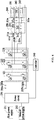
- Fig. 2 is a schematic diagram illustrating connection of an internal structure of the miter saw in Fig. 1;
- Fig. 3 is a schematic diagram illustrating connection connecting a circuit and a winding in Fig. 2;
- Fig. 4 is a schematic diagram illustrating connection of another internal structure of the miter saw in Fig. 1; and
- Fig. 5 is a schematic structural diagram illustrating a relay in Fig. 4.
- The present disclosure is described in detail below in combination with drawings and specific embodiments.
- By referring to an
electric tool 100 shown in Fig. 1 to Fig. 3, to facilitate description, a miter saw is used as one of embodiments of the electric tool for illustration. - The miter saw includes: a
base 101, a working table 102, asaw blade 103, apower circuit 110, a connectingcircuit 120 and amotor 130. Thebase 101 is configured to support the working table 102. The miter saw can be stably placed on ground or an operating plane. The working table 102 is rotatably connected to thebase 101, and is configured to place a processing piece. Thesaw blade 103 is pivotably connected with the working table 102 through a bracket, and is configured to cut the processing piece. Themotor 130 is configured to supply a power source. Themotor 130 drives thesaw blade 103 to cut the processing piece placed on the working table 102. - An integral structure of the miter saw is roughly the same as a general miter saw structure, and is not repeated in detail herein.
- Fig. 2 is a block diagram illustrating connection of an internal circuit of a miter saw. The
power circuit 110 is configured to selectively access afirst power supply 111 and asecond power supply 112 for supplying power for themotor 130, wherein thepower circuit 110 includes anoutput anode 110a and anoutput cathode 110b; thefirst power supply 111 and thesecond power supply 112 are electrically connected with thepower circuit 110; and electric energy of thefirst power supply 111 and/or thesecond power supply 112 is converted by thepower circuit 110 so that a voltage between theoutput anode 110a and theoutput cathode 110b is a preset value. - As a possible embodiment, the
first power supply 111 is a battery pack having a first voltage value and thesecond power supply 112 is a battery pack having a second voltage value, wherein the first voltage value is greater than or equal to the second voltage value. Specifically, thefirst power supply 111 and thesecond power supply 112 are detachable battery packs. - As another possible embodiment, the
first power supply 111 is an alternating current power supply having the first voltage value, and thesecond power supply 112 is a direct current power supply having the second voltage value. Specifically, a value range of the first voltage value is 210V to 230V, and a value range of the second voltage value is 110V to 130V. Thefirst power supply 111 and thesecond power supply 112 access alternating current commercial power through respective corresponding alternating current plugs. - As another possible embodiment, the
first power supply 111 accessed by thepower circuit 110 is an alternating current power supply, and thesecond power supply 112 accessed by thepower circuit 110 is a direct current power supply. Specifically, thepower circuit 110 includes afirst power supply 111 access port, asecond power supply 112 access port, and a voltage conversion circuit. Thefirst power supply 111 access port accesses thefirst power supply 111, and thesecond power supply 112 access port accesses thesecond power supply 112. The electric energy of thefirst power supply 111 accessed by thefirst power supply 111 access port is converted, through the voltage conversion circuit, into direct current voltage having a preset voltage value for output. More specifically, the voltage conversion circuit may be a rectification circuit including four semiconductor elements, and can convert alternating current into direct current for output. It should be noted that the access of thefirst power supply 111 and/or thesecond power supply 112 by thepower circuit 110 includes direct accessing or indirect accessing. - As shown in Fig. 3, the
connecting circuit 120 includes aninput anode 120a electrically connected with theoutput anode 110a, aninput cathode 120b connected with theoutput cathode 110b, afirst terminal 121a, asecond terminal 122a, a third terminal 123a and afourth terminal 124a. Theconnecting circuit 120 includes afirst connecting circuit 121, a secondconnecting circuit 122, a thirdconnecting circuit 123 and afourth connecting circuit 124, wherein thefirst connecting circuit 121 includes a first switch K1 and a second switch K2; the secondconnecting circuit 122 includes a third switch K3 and a fourth switch K4; the third connectingcircuit 123 includes a fifth switch K5 and a sixth switch K6; and thefourth connecting circuit 124 includes a seventh switch K7 and an eighth switch K8. - Specifically, the first switch K1, the second switch K2, the third switch K3, the fourth switch K4, the fifth switch K5, the sixth switch K6 and the eighth switch K8 are semiconductor switches, such as IGBT, MOSFET or semiconductor switches composed of triodes and diodes. All the above switches are MOSFET is taken as an embodiment for description below, and each of the switches has respective source electrode, gate electrode and drain electrode.
- As shown in Fig. 3, in the
first connecting circuit 121, the drain electrode of the first switch K1 is connected to theinput anode 120a; the source electrode of the second switch K2 is connected to theinput cathode 120b; the source electrode of the first switch K1 is connected with the drain electrode of the second switch K2; and thefourth terminal 124a is connected between the source electrode of the first switch K1 and the drain electrode of the second switch K2. In the second connectingcircuit 122, the drain electrode of the third switch K3 is connected to theinput anode 120a; the source electrode of the fourth switch K4 is connected to theinput cathode 120b; the source electrode of the third switch K3 is connected with the drain electrode of the fourth switch K4; and thefirst terminal 121a is connected between the source electrode of the third switch K3 and the drain electrode of the fourth switch K4. In the third connectingcircuit 123, the drain electrode of the fifth switch K5 is connected to theinput anode 120a; the source electrode of the sixth switch K6 is connected to theinput cathode 120b; the source electrode of the fifth switch K5 is connected with the drain electrode of the sixth switch K6; and thesecond terminal 122a is connected between the source electrode of the fifth switch K5 and the drain electrode of the sixth switch K6. In the fourth connectingcircuit 124, the drain electrode of the seventh switch K7 is connected to theinput anode 120a; the source electrode of the eighth switch K8 is connected to theinput cathode 120b; the source electrode of the seventh switch K7 is connected with the drain electrode of the eighth switch K8; and the third terminal 123a is connected between the source electrode of the seventh switch K7 and the drain electrode of the eighth switch K8. The gate electrodes of the first switch K1, the second switch K2, the third switch K3, the fourth switch K4, the fifth switch K5, the sixth switch K6, the seventh switch K7 and the eighth switch K8 are connected to acontroller 140 for receiving a control signal input by thecontroller 140. - The
motor 130 includes a first-phase winding 131, a second-phase winding 132 and a third-phase winding 133, wherein the first-phase winding has a first connectingend 131a and a second connecting end 131o; the second-phase winding has a thirdconnecting end 132b and a fourth connecting end 132o; and the third-phase winding has a fifth connecting end 133c and a sixth connecting end 133o. As a connection mode, as shown in Fig. 2, the second connecting end 131o, the fourth connecting end 132o and the sixth connecting end 133o are connected to a neutral point O1. - The
controller 140 is configured to send a first control signal, when thepower circuit 110 accesses thefirst power supply 111, to the switches in the connectingcircuit 120 so that the connectingcircuit 120 has a first connection state in which a first number of windings are connected between theoutput anode 110a and theoutput cathode 110b, and send a second control signal, when thepower circuit 110 accesses thesecond power supply 112, to the switches in the connectingcircuit 120 so that the connectingcircuit 120 has a second connection state in which a second number of windings are connected between theoutput anode 110a and theoutput cathode 110b. It should be noted, the first number of the windings may be a number different from that of the second number of the windings. - Specifically, when the
power circuit 110 accesses thefirst power supply 111, e.g., 220V alternating current commercial power, thecontroller 140 sends the first control signal to the switches in the connectingcircuit 120 so that the connectingcircuit 120 has a first connection state in which two phase windings, e.g. the first-phase or first winding and the second-phase or second winding, are connected in series between theoutput anode 110a and theoutput cathode 110b; when thepower circuit 110 accesses thesecond power supply 112, e.g., direct current, thecontroller 140 sends the second control signal to the switches in the connectingcircuit 120 so that the connectingcircuit 120 has a second connection state in which one phase winding,e.g. the first-phase or first winding is connected between theoutput anode 110a and theoutput cathode 110b. - In combination with Fig. 1 to Fig. 3, a work process of an angle grinder is illustrated by taking an example that the
first power supply 111 accessed by thepower circuit 110 is 220V alternating current commercial power and thesecond power supply 112 is direct current. - When the
power circuit 110 accesses the alternating current commercial power, thecontroller 140 sends a control signal which enables the third switch K3 and the sixth switch K6 to be switched on, so that the third switch K3 and the sixth switch K6 in the connectingcircuit 120 are switched on. Current output by thepower circuit 110 successively flows through theinput anode 120a, the third switch K3, the first-phase winding, the second-phase winding, the sixth switch K6 and theinput cathode 120b so as to form a closed current loop so that the first winding 131 and the second winding 132 generate magnetomotive force in space; and magnetic fields of a stator and a rotor of themotor 130 interact so that themotor 130 rotates to convert electric energy into mechanical energy for output so as to drive the saw blade to operate. To facilitate description, a conduction state of the connectingcircuit 120 when the third switch K3 and the sixth switch K6 are switched on is defined as K3K6, a driving state of themotor 130 when the first connectingend 131a is connected to theinput anode 120a and the third connectingend 132b is connected to theinput cathode 120b is defined as AB. Namely, thecontroller 140 sends a control signal which enables the third switch K3 and the sixth switch K6 to be switched on; the conduction state of the connectingcircuit 120 is K3K6; and the driving state of themotor 130 is correspondingly AB. - The
controller 140 sends a control signal which enables the fifth switch K5 and the fourth switch K4 to be switched on, so that the fifth switch K5 and the fourth switch K4 in the connectingcircuit 120 are switched on, i.e., the conduction state of the connectingcircuit 120 is K5K4. Current output by thepower circuit 110 successively flows through theinput anode 120a, the fifth switch K5, the second-phase winding 132, the fourth switch K4, the first-phase winding 131 and theinput cathode 120b so as to form a closed current loop, i.e., the driving state of themotor 130 is correspondingly BA. - The
power circuit 110 accesses the alternating current commercial power, and thecontroller 140 successively outputs different control signals to the switches in the connectingcircuit 120 so as to change the driving state of themotor 130, so that the phase windings of themotor 130 are operated according to a certain order and then themotor 130 rotates to convert electric energy into mechanical energy for output so as to drive the saw blade to operate. Table 1 is a corresponding relationship table of the conduction states of the connectingcircuit 120 and the driving states of themotor 130 within the duration of one period, i.e., the duration in which the rotor of themotor 130 rotates by one circle when thepower circuit 110 accesses the alternating current commercial power. Thecontroller 140 successively outputs corresponding control signals according to a sequence from top to bottom shown in Table 1.Table 1 Conduction State Driving State K3K6 AB K3K8 AC K5K8 BC K5K4 BA K7K4 CA K7K6 CB - It can be known from the above table that, when the
power circuit 110 accesses the alternating current commercial power, the second connecting end 131o, the fourth connecting end 132o and the sixth connecting end 133o are connected to the neutral point O1 and the three phase windings form star-shaped or Y-shaped connection. - When the
power circuit 110 accesses the direct current, such as two 56V battery packs connected in parallel, thecontroller 140 outputs a control signal, which enables the third switch K3 and the second switch K2 to be switched on, to the connectingcircuit 120 so that the third switch K3 and the second switch K2 are switched on. Current output by thepower circuit 110 successively flows through theinput anode 120a, the third switch K3, the first-phase winding, the second switch K2 and theinput cathode 120b so as to form a closed current loop so that the first-phase winding generates magnetomotive force. Similarly, to facilitate description, the conduction state of the above connectingcircuit 120 is defined as K3K2; and a state when the first connectingend 131a is connected to theinput anode 120a and the second connecting end 131o (i.e., the neutral point O1) is connected to theinput cathode 120b is defined as the driving state AO of themotor 130. - The
controller 140 outputs a control signal, which enables the first switch K1 and the fourth switch K4 to be switched on, to the connectingcircuit 120 so that the first switch K1 and the fourth switch K4 are switched on. Current output by thepower circuit 110 successively flows through theinput anode 120a, the first switch K1, the first-phase winding 131, the fourth switch K4 and theinput cathode 120b. At this moment, the second connecting end 131o (i.e., the neutral point O1) is connected to theinput anode 120a and the first connectingend 131a is connected to theinput cathode 120b. The conduction state of the connectingcircuit 120 is K1K4, and the driving state of themotor 130 is correspondingly OA. - Table 2 is a corresponding relationship table of the conduction states of the connecting
circuit 120 and the driving states of themotor 130 within the duration of one period, i.e., the duration in which the rotor of themotor 130 rotates by one circle when thepower circuit 110 accesses the direct current. Thecontroller 140 successively outputs corresponding control signals to the connectingcircuit 120 according to a sequence from top to bottom shown in Table 2, so as to drive themotor 130 to rotate. It can be known from the above table that, when thepower circuit 110 accesses the direct current, e.g. from the battery pack, the three phase windings form triangle-shaped or Δ-shaped connection.Table 2 Conduction State Driving State K3K2 AO K1K8 OC K5K2 BO K1K4 OA K7K2 CO K1K6 BO - In the miter saw of the present embodiment, when the
power circuit 110 accesses different power supplies, thecontroller 140 as a signal source responds to different accessed power supplies to output corresponding control signals to an electronic switch, thereby realizing switching of the driving states of themotor 130 between the different power supplies, ensuring that output properties of themotor 130 during accessing different power supplies are basically consistent, and enhancing use experience of the user. Meanwhile, the electronic switch realizes state switching when themotor 130 accesses different power supplies, thereby realizing low production cost and small space occupation of the electric tool, so that the integral structure of the electric tool is more compact. The output properties herein include a rotating speed, an output voltage, an output power and other property parameters of themotor 130. - It should be noted that if the
first power supply 111 and thesecond power supply 112 accessed by thepower circuit 110 are identical, and thepower circuit 110 access the same voltage, output of different rotating speeds of themotor 130 can be apparently realized by adopting the connectingcircuit 120 and thecontroller 140 in the present embodiment, thereby satisfying a demand on a working condition that thesame motor 130 outputs different rotating speeds at the same voltage. It is easy for those skilled in the art to contemplate that the solution is also within a protection scope of the present disclosure. - Refer to a schematic diagram illustrating an internal structure of a miter saw of another embodiment shown in Fig. 4 and Fig. 5. A difference from the embodiment shown in Fig. 2 and Fig. 3 is that, the miter saw further includes a
relay 240 as one of signals sources. The connectingcircuit 220 includes six electronic switches such as a first switch Q1, a second switch Q2, a third switch Q3, a fourth switch Q4, a fifth switch Q5 and a sixth switch Q6. Afirst terminal 221a is connected between the first switch Q1 and the second switch Q2. A second terminal 222b is connected between the third switch Q3 and the fourth switch Q4. Athird terminal 223c is connected between the fifth switch Q5 and the sixth switch Q6. - The
motor 230 includes a first-phase winding 231, a second-phase winding 232 and a third-phase winding 233. The first connectingend 231a of the first-phase winding 231 is connected with thefirst terminal 221a; the third connecting end 232b of the second-phase winding 232 is connected with the second terminal 222b; and the fifth connectingend 233c of the third-phase winding 233 is connected with the third connecting end 232b. - Specifically, the
relay 240 includes afirst relay 241, asecond relay 242 and athird relay 243. Eachrelay 240 has one static contact and two movable contacts. One of the static contact and the two movable contacts is defined to be connected in a first contact state of therelay 240, and another one of the static contact and the two movable contacts is defined to be connected in a second contact state of therelay 240. The static contact of thefirst relay 241 is connected to the second connecting end 231o; the static contact of thesecond relay 242 is connected to the fourth connecting end 232o; and the static contact of thethird relay 243 is connected to the sixth connecting end 233o. - A condition that the
first power supply 211 accessed by thepower circuit 210 is alternating current commercial power and the accessedsecond power supply 212 is direct current is illustrated below. - When the
power circuit 210 accesses the alternating current commercial power, thefirst relay 241, thesecond relay 242 and thethird relay 243 are in the first contact state. Namely, the firststatic contact 241a is connected to the secondmovable contact 241c; the secondstatic contact 242a is connected to the fourthmovable contact 242c; and the thirdstatic contact 243a is connected to the sixthmovable contact 243c. Meanwhile, the controller outputs a control signal that enables the first switch Q1 and the fourth switch Q4 to be switched on so that the first connectingend 231a is connected to the output anode of thepower circuit 210 and the third connecting end 232b is connected to the output cathode of thepower circuit 210. In other words, the conduction state of the connectingcircuit 220 is Q1Q4; and the driving state of themotor 230 is correspondingly AB. Similarly, the controller successively outputs corresponding control signals to the connectingcircuit 220 according to a sequence from top to bottom shown in Table 3, so as to drive themotor 230 to rotate.Table 3 Conduction State Driving State Q1Q4 AB Q1Q6 AC Q3Q6 BC Q3Q2 BA Q6Q2 CA Q6Q4 CB - It can be known from Table 3 that when the
power circuit 210 accesses the alternating current commercial power, the second connecting end 231o, the fourth connecting end 232o and the sixth connecting end 233o are connected to the neutral point O2 and the three phase windings form star-shaped connection. Namely, only the second connecting end 231o in two connecting ends of the first-phase winding 231 is connected to the second-phase winding 232 and the third-phase winding 233. - When the
power circuit 210 accesses the direct current, thefirst relay 241, thesecond relay 242 and thethird relay 243 are in the first contact state. Namely, the firststatic contact 241a is connected to the firstmovable contact 241b; the secondstatic contact 242a is connected to the thirdmovable contact 242b; and the thirdstatic contact 243a is connected to the fifthmovable contact 243b. Meanwhile, the controller outputs a control signal that enables the first switch Q1 and the fourth switch Q4 to be switched on so that the first connectingend 231a is connected to the output anode of thepower circuit 210 and the third connecting end 232b is connected to the output cathode of thepower circuit 210. In other words, the conduction state of the connectingcircuit 220 is Q1Q4; and the driving state of themotor 230 is correspondingly AB. - It should be noted that when the
power circuit 210 accesses the direct current, the controller also successively outputs corresponding control signals to the connectingcircuit 220 according to a sequence from top to bottom shown in Table 3, so as to drive themotor 230 to rotate. A difference from accessing the alternating current is that the three phase windings of themotor 230 form angular connection. Namely, two connecting ends of the first-phase winding 231 are respectively connected to one end of the second-phase winding 232 and the third-phase winding. - The miter saw in above embodiments can also realize the change of the driving states of the
motor 230 when thepower circuit 210 accesses different power supplies, so that themotor 230 has approximately the same output properties when switching between accessing two different power supplies. - The above shows and describes a basic principle, main features and advantages of the present disclosure. Those skilled in the art should understand that above embodiments do not limit the present disclosure in any form. Technical solutions obtained by adopting equivalent replacements or equivalent transformations fall within the protection scope of the present disclosure.
Claims (10)
- An electric tool, comprising:a motor comprising a plurality of windings;a power circuit configured to selectively access a first power supply and a second power supply for supplying power for the motor and comprising an output anode and an output cathode for outputting electric energy;a connecting circuit comprising a switching device configured to enable the connecting circuit to have a first connection state in which a first number of windings are connected between the output anode and the output cathode and a second connection state in which a second number of windings are connected between the output anode and the output cathode; anda signal source configured to send a first control signal, when the power circuit accesses the first power supply, to the switching device so that the connecting circuit is in the first connection state, and send a second control signal, when the power circuit accesses the second power supply, to the switching device so that the connecting circuit is in the second connection state;wherein the connecting circuit is electrically connected with the motor and the power circuit, and the signal source is electrically connected with the connecting circuit.
- The electric tool according to claim 1, wherein
the connecting circuit has a first connection state in which a first number of windings are connected in series between the output anode and the output cathode and a second connection state in which a second number of windings are connected in series between the output anode and the output cathode. - The electric tool according to claim 1, wherein
a voltage of the first power supply accessed by the power circuit is greater than or equal to a voltage of the second power supply accessed by the power circuit. - The electric tool according to claim 1, wherein
the first power supply accessed by the power circuit is an alternating current power supply, and the second power supply accessed by the power circuit is a direct current power supply. - The electric tool according to claim 1, wherein
the signal source is a controller and/or a relay. - An electric tool, comprising:a motor comprising a first winding, a second winding and a third winding;a power circuit configured to selectively connect a first power supply and a second power supply for supplying power for the motor and comprising an output anode and an output cathode;a connecting circuit comprising:a first connecting circuit comprising a first switch and a second switch, wherein one of two connecting ends of the first winding is connected between the first switch and the second switch;a second connecting circuit comprising a third switch and a fourth switch, wherein the other one of two connecting ends of the first winding is connected between the third switch and the fourth switch;a third connecting circuit comprising a fifth switch and a sixth switch, wherein one of two connecting ends of the second winding is connected between the fifth switch and the sixth switch; anda fourth connecting circuit comprising a seventh switch and an eighth switch, wherein one of two connecting ends of the third winding is connected between the seventh switch and the eighth switch; anda signal source configured to send a first control signal, when the power circuit accesses the first power supply, to the first switch, the second switch, the third switch, the fourth switch, the fifth switch, the sixth switch, the seventh switch and the eighth switch so that the first winding is connected between the output anode and the output cathode, and send a second control signal, when the power circuit accesses the second power supply, to the first switch, the second switch, the third switch, the fourth switch, the fifth switch, the sixth switch, the seventh switch and the eighth switch so that the first winding and the second winding are connected between the output anode and the output cathode;wherein the connecting circuit is electrically connected with the power circuit and the motor, and the signal source is electrically connected with the connecting circuit.
- The electric tool according to claim 6, wherein
a voltage of the first power supply accessed by the power circuit is greater than a voltage of the second power supply accessed by the power circuit. - The electric tool according to claim 6, wherein
the first power supply accessed by the power circuit is an alternating current power supply, and the second power supply accessed by the power circuit is a direct current power supply. - The electric tool according to claim 6, wherein
the signal source comprises a controller or a relay. - An electric tool, comprising:a motor comprising a plurality of windings;a power circuit configured to selectively access a first power supply and a second power supply for supplying power for the motor;a connecting circuit comprising a switching device configured to enable the connecting circuit to have a first state in which only one of two connecting ends of the winding is connected to other windings and a second state in which two connecting ends of the winding are respectively connected to different windings; anda signal source configured to send a first control signal, when the power circuit accesses the first power supply, to the switching device so that the connecting circuit is in the first connection state, and send a second control signal, when the power circuit accesses the second power supply, to the switching device so that the connecting circuit is in the second connection state.
Applications Claiming Priority (1)
| Application Number | Priority Date | Filing Date | Title |
|---|---|---|---|
| CN201710053549.0A CN108340323A (en) | 2017-01-24 | 2017-01-24 | Electric tool |
Publications (2)
| Publication Number | Publication Date |
|---|---|
| EP3354410A1 true EP3354410A1 (en) | 2018-08-01 |
| EP3354410B1 EP3354410B1 (en) | 2021-07-28 |
Family
ID=60997334
Family Applications (1)
| Application Number | Title | Priority Date | Filing Date |
|---|---|---|---|
| EP18151754.1A Active EP3354410B1 (en) | 2017-01-24 | 2018-01-16 | Electric tool |
Country Status (3)
| Country | Link |
|---|---|
| US (1) | US20180212546A1 (en) |
| EP (1) | EP3354410B1 (en) |
| CN (1) | CN108340323A (en) |
Citations (3)
| Publication number | Priority date | Publication date | Assignee | Title |
|---|---|---|---|---|
| WO2013081191A2 (en) * | 2011-11-30 | 2013-06-06 | Hitachi Koki Co., Ltd. | Electric tool |
| EP2944432A1 (en) * | 2014-05-16 | 2015-11-18 | Techtronic Power Tools Technology Limited | Multi-battery pack for power tools |
| WO2016194535A1 (en) * | 2015-05-29 | 2016-12-08 | 日立工機株式会社 | Electric tool |
Family Cites Families (9)
| Publication number | Priority date | Publication date | Assignee | Title |
|---|---|---|---|---|
| US5557180A (en) * | 1993-06-30 | 1996-09-17 | Sgs-Thomson Microelectronics, Inc. | Circuit and method for operating a 3-phase motor with a uni-coil phase commutation scheme |
| US7602137B2 (en) * | 2006-02-20 | 2009-10-13 | Black & Decker Inc. | Electronically commutated motor and control system |
| US7479754B2 (en) * | 2006-10-17 | 2009-01-20 | Desa Ip Llc | Hybrid electric lawnmower |
| CN102237734B (en) * | 2010-04-23 | 2015-08-12 | 德昌电机(深圳)有限公司 | A kind of motor |
| JP2014069252A (en) * | 2012-09-28 | 2014-04-21 | Hitachi Koki Co Ltd | Power tool |
| JP5938341B2 (en) * | 2012-12-18 | 2016-06-22 | 日立建機株式会社 | Electric construction machine |
| CN203221473U (en) * | 2013-05-08 | 2013-10-02 | 国家电网公司 | Alternating-current and direct-current multifunctional electric tool |
| JP6286149B2 (en) * | 2013-08-02 | 2018-02-28 | 日立オートモティブシステムズ株式会社 | Power converter, electric power steering system, electric vehicle, electronic control throttle, electric brake |
| CN104969722B (en) * | 2015-06-11 | 2017-07-07 | 浙江亚特电器有限公司 | A kind of power-operated mower |
-
2017
- 2017-01-24 CN CN201710053549.0A patent/CN108340323A/en active Pending
-
2018
- 2018-01-16 EP EP18151754.1A patent/EP3354410B1/en active Active
- 2018-01-23 US US15/877,903 patent/US20180212546A1/en not_active Abandoned
Patent Citations (4)
| Publication number | Priority date | Publication date | Assignee | Title |
|---|---|---|---|---|
| WO2013081191A2 (en) * | 2011-11-30 | 2013-06-06 | Hitachi Koki Co., Ltd. | Electric tool |
| EP2944432A1 (en) * | 2014-05-16 | 2015-11-18 | Techtronic Power Tools Technology Limited | Multi-battery pack for power tools |
| WO2016194535A1 (en) * | 2015-05-29 | 2016-12-08 | 日立工機株式会社 | Electric tool |
| EP3306808A1 (en) * | 2015-05-29 | 2018-04-11 | Hitachi Koki Co., Ltd. | Electric tool |
Also Published As
| Publication number | Publication date |
|---|---|
| CN108340323A (en) | 2018-07-31 |
| US20180212546A1 (en) | 2018-07-26 |
| EP3354410B1 (en) | 2021-07-28 |
Similar Documents
| Publication | Publication Date | Title |
|---|---|---|
| CN109873578B (en) | Electric tool and control method thereof | |
| CN109842326B (en) | Angle Grinders & Power Tools | |
| US20200230718A1 (en) | Circular saw | |
| EP2797221A1 (en) | Motor winding and power electronic switch assembly having switchable output capability | |
| CN108011559B (en) | Electric tool and control method of electric tool | |
| US10868462B2 (en) | Power tool | |
| EP3354410B1 (en) | Electric tool | |
| CN113224987B (en) | Starting self-checking method of electric tool and electric tool | |
| JPH09247903A (en) | Electric motor with control device | |
| US7498764B2 (en) | Control device for driving regulating motor | |
| CA2631553A1 (en) | Rechargeable vacuum with reduced ac voltage | |
| CN204091717U (en) | A kind of soy bean milk making machine | |
| CN115580200B (en) | Electric tool and drive control circuit thereof | |
| CN216162529U (en) | Permanent magnet brushless motor based on remote control | |
| CN208004924U (en) | A kind of condenser steel wire cutter device | |
| US20110012549A1 (en) | Electric motor | |
| EP4231519A1 (en) | Power tool and control method therefor | |
| CN203691052U (en) | Improved double-power-supply automatic conversion device | |
| CN108890734A (en) | One kind is for cutting lithium battery diaphragm cutter | |
| CN209119822U (en) | A new type of commutation switch | |
| CN114513159A (en) | Structure of universal three-phase motor controller | |
| CN222691609U (en) | A soft starter circuit for towing motor | |
| TW200503383A (en) | Parallel driving circuit of synchronous motor | |
| CN221509434U (en) | Control circuit compatible with high voltage and low voltage and electric tool | |
| CN209448725U (en) | Three phase rectifier reversing switch |
Legal Events
| Date | Code | Title | Description |
|---|---|---|---|
| PUAI | Public reference made under article 153(3) epc to a published international application that has entered the european phase |
Free format text: ORIGINAL CODE: 0009012 |
|
| STAA | Information on the status of an ep patent application or granted ep patent |
Free format text: STATUS: THE APPLICATION HAS BEEN PUBLISHED |
|
| AK | Designated contracting states |
Kind code of ref document: A1 Designated state(s): AL AT BE BG CH CY CZ DE DK EE ES FI FR GB GR HR HU IE IS IT LI LT LU LV MC MK MT NL NO PL PT RO RS SE SI SK SM TR |
|
| AX | Request for extension of the european patent |
Extension state: BA ME |
|
| STAA | Information on the status of an ep patent application or granted ep patent |
Free format text: STATUS: REQUEST FOR EXAMINATION WAS MADE |
|
| 17P | Request for examination filed |
Effective date: 20180727 |
|
| RBV | Designated contracting states (corrected) |
Designated state(s): AL AT BE BG CH CY CZ DE DK EE ES FI FR GB GR HR HU IE IS IT LI LT LU LV MC MK MT NL NO PL PT RO RS SE SI SK SM TR |
|
| STAA | Information on the status of an ep patent application or granted ep patent |
Free format text: STATUS: EXAMINATION IS IN PROGRESS |
|
| 17Q | First examination report despatched |
Effective date: 20181205 |
|
| GRAP | Despatch of communication of intention to grant a patent |
Free format text: ORIGINAL CODE: EPIDOSNIGR1 |
|
| STAA | Information on the status of an ep patent application or granted ep patent |
Free format text: STATUS: GRANT OF PATENT IS INTENDED |
|
| GRAS | Grant fee paid |
Free format text: ORIGINAL CODE: EPIDOSNIGR3 |
|
| INTG | Intention to grant announced |
Effective date: 20210527 |
|
| GRAA | (expected) grant |
Free format text: ORIGINAL CODE: 0009210 |
|
| STAA | Information on the status of an ep patent application or granted ep patent |
Free format text: STATUS: THE PATENT HAS BEEN GRANTED |
|
| AK | Designated contracting states |
Kind code of ref document: B1 Designated state(s): AL AT BE BG CH CY CZ DE DK EE ES FI FR GB GR HR HU IE IS IT LI LT LU LV MC MK MT NL NO PL PT RO RS SE SI SK SM TR |
|
| REG | Reference to a national code |
Ref country code: GB Ref legal event code: FG4D |
|
| REG | Reference to a national code |
Ref country code: CH Ref legal event code: EP |
|
| REG | Reference to a national code |
Ref country code: AT Ref legal event code: REF Ref document number: 1414298 Country of ref document: AT Kind code of ref document: T Effective date: 20210815 |
|
| REG | Reference to a national code |
Ref country code: IE Ref legal event code: FG4D |
|
| REG | Reference to a national code |
Ref country code: DE Ref legal event code: R096 Ref document number: 602018020628 Country of ref document: DE |
|
| REG | Reference to a national code |
Ref country code: LT Ref legal event code: MG9D |
|
| REG | Reference to a national code |
Ref country code: NL Ref legal event code: MP Effective date: 20210728 |
|
| REG | Reference to a national code |
Ref country code: AT Ref legal event code: MK05 Ref document number: 1414298 Country of ref document: AT Kind code of ref document: T Effective date: 20210728 |
|
| PG25 | Lapsed in a contracting state [announced via postgrant information from national office to epo] |
Ref country code: NO Free format text: LAPSE BECAUSE OF FAILURE TO SUBMIT A TRANSLATION OF THE DESCRIPTION OR TO PAY THE FEE WITHIN THE PRESCRIBED TIME-LIMIT Effective date: 20211028 Ref country code: NL Free format text: LAPSE BECAUSE OF FAILURE TO SUBMIT A TRANSLATION OF THE DESCRIPTION OR TO PAY THE FEE WITHIN THE PRESCRIBED TIME-LIMIT Effective date: 20210728 Ref country code: PT Free format text: LAPSE BECAUSE OF FAILURE TO SUBMIT A TRANSLATION OF THE DESCRIPTION OR TO PAY THE FEE WITHIN THE PRESCRIBED TIME-LIMIT Effective date: 20211129 Ref country code: LT Free format text: LAPSE BECAUSE OF FAILURE TO SUBMIT A TRANSLATION OF THE DESCRIPTION OR TO PAY THE FEE WITHIN THE PRESCRIBED TIME-LIMIT Effective date: 20210728 Ref country code: BG Free format text: LAPSE BECAUSE OF FAILURE TO SUBMIT A TRANSLATION OF THE DESCRIPTION OR TO PAY THE FEE WITHIN THE PRESCRIBED TIME-LIMIT Effective date: 20211028 Ref country code: AT Free format text: LAPSE BECAUSE OF FAILURE TO SUBMIT A TRANSLATION OF THE DESCRIPTION OR TO PAY THE FEE WITHIN THE PRESCRIBED TIME-LIMIT Effective date: 20210728 Ref country code: RS Free format text: LAPSE BECAUSE OF FAILURE TO SUBMIT A TRANSLATION OF THE DESCRIPTION OR TO PAY THE FEE WITHIN THE PRESCRIBED TIME-LIMIT Effective date: 20210728 Ref country code: SE Free format text: LAPSE BECAUSE OF FAILURE TO SUBMIT A TRANSLATION OF THE DESCRIPTION OR TO PAY THE FEE WITHIN THE PRESCRIBED TIME-LIMIT Effective date: 20210728 Ref country code: HR Free format text: LAPSE BECAUSE OF FAILURE TO SUBMIT A TRANSLATION OF THE DESCRIPTION OR TO PAY THE FEE WITHIN THE PRESCRIBED TIME-LIMIT Effective date: 20210728 Ref country code: ES Free format text: LAPSE BECAUSE OF FAILURE TO SUBMIT A TRANSLATION OF THE DESCRIPTION OR TO PAY THE FEE WITHIN THE PRESCRIBED TIME-LIMIT Effective date: 20210728 Ref country code: FI Free format text: LAPSE BECAUSE OF FAILURE TO SUBMIT A TRANSLATION OF THE DESCRIPTION OR TO PAY THE FEE WITHIN THE PRESCRIBED TIME-LIMIT Effective date: 20210728 |
|
| PG25 | Lapsed in a contracting state [announced via postgrant information from national office to epo] |
Ref country code: PL Free format text: LAPSE BECAUSE OF FAILURE TO SUBMIT A TRANSLATION OF THE DESCRIPTION OR TO PAY THE FEE WITHIN THE PRESCRIBED TIME-LIMIT Effective date: 20210728 Ref country code: LV Free format text: LAPSE BECAUSE OF FAILURE TO SUBMIT A TRANSLATION OF THE DESCRIPTION OR TO PAY THE FEE WITHIN THE PRESCRIBED TIME-LIMIT Effective date: 20210728 Ref country code: GR Free format text: LAPSE BECAUSE OF FAILURE TO SUBMIT A TRANSLATION OF THE DESCRIPTION OR TO PAY THE FEE WITHIN THE PRESCRIBED TIME-LIMIT Effective date: 20211029 |
|
| PG25 | Lapsed in a contracting state [announced via postgrant information from national office to epo] |
Ref country code: DK Free format text: LAPSE BECAUSE OF FAILURE TO SUBMIT A TRANSLATION OF THE DESCRIPTION OR TO PAY THE FEE WITHIN THE PRESCRIBED TIME-LIMIT Effective date: 20210728 |
|
| REG | Reference to a national code |
Ref country code: DE Ref legal event code: R097 Ref document number: 602018020628 Country of ref document: DE |
|
| PG25 | Lapsed in a contracting state [announced via postgrant information from national office to epo] |
Ref country code: SM Free format text: LAPSE BECAUSE OF FAILURE TO SUBMIT A TRANSLATION OF THE DESCRIPTION OR TO PAY THE FEE WITHIN THE PRESCRIBED TIME-LIMIT Effective date: 20210728 Ref country code: SK Free format text: LAPSE BECAUSE OF FAILURE TO SUBMIT A TRANSLATION OF THE DESCRIPTION OR TO PAY THE FEE WITHIN THE PRESCRIBED TIME-LIMIT Effective date: 20210728 Ref country code: RO Free format text: LAPSE BECAUSE OF FAILURE TO SUBMIT A TRANSLATION OF THE DESCRIPTION OR TO PAY THE FEE WITHIN THE PRESCRIBED TIME-LIMIT Effective date: 20210728 Ref country code: EE Free format text: LAPSE BECAUSE OF FAILURE TO SUBMIT A TRANSLATION OF THE DESCRIPTION OR TO PAY THE FEE WITHIN THE PRESCRIBED TIME-LIMIT Effective date: 20210728 Ref country code: CZ Free format text: LAPSE BECAUSE OF FAILURE TO SUBMIT A TRANSLATION OF THE DESCRIPTION OR TO PAY THE FEE WITHIN THE PRESCRIBED TIME-LIMIT Effective date: 20210728 Ref country code: AL Free format text: LAPSE BECAUSE OF FAILURE TO SUBMIT A TRANSLATION OF THE DESCRIPTION OR TO PAY THE FEE WITHIN THE PRESCRIBED TIME-LIMIT Effective date: 20210728 |
|
| PLBE | No opposition filed within time limit |
Free format text: ORIGINAL CODE: 0009261 |
|
| STAA | Information on the status of an ep patent application or granted ep patent |
Free format text: STATUS: NO OPPOSITION FILED WITHIN TIME LIMIT |
|
| 26N | No opposition filed |
Effective date: 20220429 |
|
| PG25 | Lapsed in a contracting state [announced via postgrant information from national office to epo] |
Ref country code: IT Free format text: LAPSE BECAUSE OF FAILURE TO SUBMIT A TRANSLATION OF THE DESCRIPTION OR TO PAY THE FEE WITHIN THE PRESCRIBED TIME-LIMIT Effective date: 20210728 |
|
| PG25 | Lapsed in a contracting state [announced via postgrant information from national office to epo] |
Ref country code: MC Free format text: LAPSE BECAUSE OF FAILURE TO SUBMIT A TRANSLATION OF THE DESCRIPTION OR TO PAY THE FEE WITHIN THE PRESCRIBED TIME-LIMIT Effective date: 20210728 |
|
| REG | Reference to a national code |
Ref country code: CH Ref legal event code: PL |
|
| REG | Reference to a national code |
Ref country code: BE Ref legal event code: MM Effective date: 20220131 |
|
| PG25 | Lapsed in a contracting state [announced via postgrant information from national office to epo] |
Ref country code: LU Free format text: LAPSE BECAUSE OF NON-PAYMENT OF DUE FEES Effective date: 20220116 |
|
| PG25 | Lapsed in a contracting state [announced via postgrant information from national office to epo] |
Ref country code: BE Free format text: LAPSE BECAUSE OF NON-PAYMENT OF DUE FEES Effective date: 20220131 |
|
| PG25 | Lapsed in a contracting state [announced via postgrant information from national office to epo] |
Ref country code: LI Free format text: LAPSE BECAUSE OF NON-PAYMENT OF DUE FEES Effective date: 20220131 Ref country code: CH Free format text: LAPSE BECAUSE OF NON-PAYMENT OF DUE FEES Effective date: 20220131 |
|
| PG25 | Lapsed in a contracting state [announced via postgrant information from national office to epo] |
Ref country code: IE Free format text: LAPSE BECAUSE OF NON-PAYMENT OF DUE FEES Effective date: 20220116 |
|
| PG25 | Lapsed in a contracting state [announced via postgrant information from national office to epo] |
Ref country code: HU Free format text: LAPSE BECAUSE OF FAILURE TO SUBMIT A TRANSLATION OF THE DESCRIPTION OR TO PAY THE FEE WITHIN THE PRESCRIBED TIME-LIMIT; INVALID AB INITIO Effective date: 20180116 |
|
| PG25 | Lapsed in a contracting state [announced via postgrant information from national office to epo] |
Ref country code: MK Free format text: LAPSE BECAUSE OF FAILURE TO SUBMIT A TRANSLATION OF THE DESCRIPTION OR TO PAY THE FEE WITHIN THE PRESCRIBED TIME-LIMIT Effective date: 20210728 Ref country code: CY Free format text: LAPSE BECAUSE OF FAILURE TO SUBMIT A TRANSLATION OF THE DESCRIPTION OR TO PAY THE FEE WITHIN THE PRESCRIBED TIME-LIMIT Effective date: 20210728 |
|
| PG25 | Lapsed in a contracting state [announced via postgrant information from national office to epo] |
Ref country code: MT Free format text: LAPSE BECAUSE OF FAILURE TO SUBMIT A TRANSLATION OF THE DESCRIPTION OR TO PAY THE FEE WITHIN THE PRESCRIBED TIME-LIMIT Effective date: 20210728 |
|
| PG25 | Lapsed in a contracting state [announced via postgrant information from national office to epo] |
Ref country code: TR Free format text: LAPSE BECAUSE OF FAILURE TO SUBMIT A TRANSLATION OF THE DESCRIPTION OR TO PAY THE FEE WITHIN THE PRESCRIBED TIME-LIMIT Effective date: 20210728 |
|
| PGFP | Annual fee paid to national office [announced via postgrant information from national office to epo] |
Ref country code: GB Payment date: 20251127 Year of fee payment: 9 |
|
| PGFP | Annual fee paid to national office [announced via postgrant information from national office to epo] |
Ref country code: FR Payment date: 20251117 Year of fee payment: 9 |
|
| PGFP | Annual fee paid to national office [announced via postgrant information from national office to epo] |
Ref country code: DE Payment date: 20251119 Year of fee payment: 9 |