EP3354380A1 - Additive manufacturing system, article, and method of manufacturing an article - Google Patents
Additive manufacturing system, article, and method of manufacturing an article Download PDFInfo
- Publication number
- EP3354380A1 EP3354380A1 EP18153391.0A EP18153391A EP3354380A1 EP 3354380 A1 EP3354380 A1 EP 3354380A1 EP 18153391 A EP18153391 A EP 18153391A EP 3354380 A1 EP3354380 A1 EP 3354380A1
- Authority
- EP
- European Patent Office
- Prior art keywords
- powder material
- article
- powder
- layer thickness
- feature
- Prior art date
- Legal status (The legal status is an assumption and is not a legal conclusion. Google has not performed a legal analysis and makes no representation as to the accuracy of the status listed.)
- Granted
Links
Images




Classifications
-
- B—PERFORMING OPERATIONS; TRANSPORTING
- B22—CASTING; POWDER METALLURGY
- B22F—WORKING METALLIC POWDER; MANUFACTURE OF ARTICLES FROM METALLIC POWDER; MAKING METALLIC POWDER; APPARATUS OR DEVICES SPECIALLY ADAPTED FOR METALLIC POWDER
- B22F5/00—Manufacture of workpieces or articles from metallic powder characterised by the special shape of the product
- B22F5/009—Manufacture of workpieces or articles from metallic powder characterised by the special shape of the product of turbine components other than turbine blades
-
- B—PERFORMING OPERATIONS; TRANSPORTING
- B22—CASTING; POWDER METALLURGY
- B22F—WORKING METALLIC POWDER; MANUFACTURE OF ARTICLES FROM METALLIC POWDER; MAKING METALLIC POWDER; APPARATUS OR DEVICES SPECIALLY ADAPTED FOR METALLIC POWDER
- B22F10/00—Additive manufacturing of workpieces or articles from metallic powder
- B22F10/20—Direct sintering or melting
- B22F10/28—Powder bed fusion, e.g. selective laser melting [SLM] or electron beam melting [EBM]
-
- B—PERFORMING OPERATIONS; TRANSPORTING
- B22—CASTING; POWDER METALLURGY
- B22F—WORKING METALLIC POWDER; MANUFACTURE OF ARTICLES FROM METALLIC POWDER; MAKING METALLIC POWDER; APPARATUS OR DEVICES SPECIALLY ADAPTED FOR METALLIC POWDER
- B22F10/00—Additive manufacturing of workpieces or articles from metallic powder
- B22F10/30—Process control
- B22F10/34—Process control of powder characteristics, e.g. density, oxidation or flowability
-
- B—PERFORMING OPERATIONS; TRANSPORTING
- B22—CASTING; POWDER METALLURGY
- B22F—WORKING METALLIC POWDER; MANUFACTURE OF ARTICLES FROM METALLIC POWDER; MAKING METALLIC POWDER; APPARATUS OR DEVICES SPECIALLY ADAPTED FOR METALLIC POWDER
- B22F10/00—Additive manufacturing of workpieces or articles from metallic powder
- B22F10/30—Process control
- B22F10/37—Process control of powder bed aspects, e.g. density
-
- B—PERFORMING OPERATIONS; TRANSPORTING
- B22—CASTING; POWDER METALLURGY
- B22F—WORKING METALLIC POWDER; MANUFACTURE OF ARTICLES FROM METALLIC POWDER; MAKING METALLIC POWDER; APPARATUS OR DEVICES SPECIALLY ADAPTED FOR METALLIC POWDER
- B22F10/00—Additive manufacturing of workpieces or articles from metallic powder
- B22F10/30—Process control
- B22F10/38—Process control to achieve specific product aspects, e.g. surface smoothness, density, porosity or hollow structures
-
- B—PERFORMING OPERATIONS; TRANSPORTING
- B22—CASTING; POWDER METALLURGY
- B22F—WORKING METALLIC POWDER; MANUFACTURE OF ARTICLES FROM METALLIC POWDER; MAKING METALLIC POWDER; APPARATUS OR DEVICES SPECIALLY ADAPTED FOR METALLIC POWDER
- B22F12/00—Apparatus or devices specially adapted for additive manufacturing; Auxiliary means for additive manufacturing; Combinations of additive manufacturing apparatus or devices with other processing apparatus or devices
- B22F12/50—Means for feeding of material, e.g. heads
- B22F12/52—Hoppers
-
- B—PERFORMING OPERATIONS; TRANSPORTING
- B22—CASTING; POWDER METALLURGY
- B22F—WORKING METALLIC POWDER; MANUFACTURE OF ARTICLES FROM METALLIC POWDER; MAKING METALLIC POWDER; APPARATUS OR DEVICES SPECIALLY ADAPTED FOR METALLIC POWDER
- B22F5/00—Manufacture of workpieces or articles from metallic powder characterised by the special shape of the product
- B22F5/10—Manufacture of workpieces or articles from metallic powder characterised by the special shape of the product of articles with cavities or holes, not otherwise provided for in the preceding subgroups
-
- B—PERFORMING OPERATIONS; TRANSPORTING
- B22—CASTING; POWDER METALLURGY
- B22F—WORKING METALLIC POWDER; MANUFACTURE OF ARTICLES FROM METALLIC POWDER; MAKING METALLIC POWDER; APPARATUS OR DEVICES SPECIALLY ADAPTED FOR METALLIC POWDER
- B22F7/00—Manufacture of composite layers, workpieces, or articles, comprising metallic powder, by sintering the powder, with or without compacting wherein at least one part is obtained by sintering or compression
- B22F7/008—Manufacture of composite layers, workpieces, or articles, comprising metallic powder, by sintering the powder, with or without compacting wherein at least one part is obtained by sintering or compression characterised by the composition
-
- B—PERFORMING OPERATIONS; TRANSPORTING
- B22—CASTING; POWDER METALLURGY
- B22F—WORKING METALLIC POWDER; MANUFACTURE OF ARTICLES FROM METALLIC POWDER; MAKING METALLIC POWDER; APPARATUS OR DEVICES SPECIALLY ADAPTED FOR METALLIC POWDER
- B22F7/00—Manufacture of composite layers, workpieces, or articles, comprising metallic powder, by sintering the powder, with or without compacting wherein at least one part is obtained by sintering or compression
- B22F7/02—Manufacture of composite layers, workpieces, or articles, comprising metallic powder, by sintering the powder, with or without compacting wherein at least one part is obtained by sintering or compression of composite layers
-
- B—PERFORMING OPERATIONS; TRANSPORTING
- B23—MACHINE TOOLS; METAL-WORKING NOT OTHERWISE PROVIDED FOR
- B23K—SOLDERING OR UNSOLDERING; WELDING; CLADDING OR PLATING BY SOLDERING OR WELDING; CUTTING BY APPLYING HEAT LOCALLY, e.g. FLAME CUTTING; WORKING BY LASER BEAM
- B23K15/00—Electron-beam welding or cutting
- B23K15/0046—Welding
- B23K15/0086—Welding welding for purposes other than joining, e.g. build-up welding
-
- B—PERFORMING OPERATIONS; TRANSPORTING
- B23—MACHINE TOOLS; METAL-WORKING NOT OTHERWISE PROVIDED FOR
- B23K—SOLDERING OR UNSOLDERING; WELDING; CLADDING OR PLATING BY SOLDERING OR WELDING; CUTTING BY APPLYING HEAT LOCALLY, e.g. FLAME CUTTING; WORKING BY LASER BEAM
- B23K15/00—Electron-beam welding or cutting
- B23K15/0046—Welding
- B23K15/0093—Welding characterised by the properties of the materials to be welded
-
- B—PERFORMING OPERATIONS; TRANSPORTING
- B23—MACHINE TOOLS; METAL-WORKING NOT OTHERWISE PROVIDED FOR
- B23K—SOLDERING OR UNSOLDERING; WELDING; CLADDING OR PLATING BY SOLDERING OR WELDING; CUTTING BY APPLYING HEAT LOCALLY, e.g. FLAME CUTTING; WORKING BY LASER BEAM
- B23K26/00—Working by laser beam, e.g. welding, cutting or boring
- B23K26/0006—Working by laser beam, e.g. welding, cutting or boring taking account of the properties of the material involved
-
- B—PERFORMING OPERATIONS; TRANSPORTING
- B23—MACHINE TOOLS; METAL-WORKING NOT OTHERWISE PROVIDED FOR
- B23K—SOLDERING OR UNSOLDERING; WELDING; CLADDING OR PLATING BY SOLDERING OR WELDING; CUTTING BY APPLYING HEAT LOCALLY, e.g. FLAME CUTTING; WORKING BY LASER BEAM
- B23K26/00—Working by laser beam, e.g. welding, cutting or boring
- B23K26/34—Laser welding for purposes other than joining
- B23K26/342—Build-up welding
-
- B—PERFORMING OPERATIONS; TRANSPORTING
- B23—MACHINE TOOLS; METAL-WORKING NOT OTHERWISE PROVIDED FOR
- B23K—SOLDERING OR UNSOLDERING; WELDING; CLADDING OR PLATING BY SOLDERING OR WELDING; CUTTING BY APPLYING HEAT LOCALLY, e.g. FLAME CUTTING; WORKING BY LASER BEAM
- B23K26/00—Working by laser beam, e.g. welding, cutting or boring
- B23K26/70—Auxiliary operations or equipment
- B23K26/702—Auxiliary equipment
-
- B—PERFORMING OPERATIONS; TRANSPORTING
- B28—WORKING CEMENT, CLAY, OR STONE
- B28B—SHAPING CLAY OR OTHER CERAMIC COMPOSITIONS; SHAPING SLAG; SHAPING MIXTURES CONTAINING CEMENTITIOUS MATERIAL, e.g. PLASTER
- B28B1/00—Producing shaped prefabricated articles from the material
- B28B1/001—Rapid manufacturing of 3D objects by additive depositing, agglomerating or laminating of material
-
- B—PERFORMING OPERATIONS; TRANSPORTING
- B29—WORKING OF PLASTICS; WORKING OF SUBSTANCES IN A PLASTIC STATE IN GENERAL
- B29C—SHAPING OR JOINING OF PLASTICS; SHAPING OF MATERIAL IN A PLASTIC STATE, NOT OTHERWISE PROVIDED FOR; AFTER-TREATMENT OF THE SHAPED PRODUCTS, e.g. REPAIRING
- B29C64/00—Additive manufacturing, i.e. manufacturing of three-dimensional [3D] objects by additive deposition, additive agglomeration or additive layering, e.g. by 3D printing, stereolithography or selective laser sintering
- B29C64/10—Processes of additive manufacturing
- B29C64/141—Processes of additive manufacturing using only solid materials
- B29C64/153—Processes of additive manufacturing using only solid materials using layers of powder being selectively joined, e.g. by selective laser sintering or melting
-
- B—PERFORMING OPERATIONS; TRANSPORTING
- B33—ADDITIVE MANUFACTURING TECHNOLOGY
- B33Y—ADDITIVE MANUFACTURING, i.e. MANUFACTURING OF THREE-DIMENSIONAL [3D] OBJECTS BY ADDITIVE DEPOSITION, ADDITIVE AGGLOMERATION OR ADDITIVE LAYERING, e.g. BY 3D PRINTING, STEREOLITHOGRAPHY OR SELECTIVE LASER SINTERING
- B33Y10/00—Processes of additive manufacturing
-
- B—PERFORMING OPERATIONS; TRANSPORTING
- B33—ADDITIVE MANUFACTURING TECHNOLOGY
- B33Y—ADDITIVE MANUFACTURING, i.e. MANUFACTURING OF THREE-DIMENSIONAL [3D] OBJECTS BY ADDITIVE DEPOSITION, ADDITIVE AGGLOMERATION OR ADDITIVE LAYERING, e.g. BY 3D PRINTING, STEREOLITHOGRAPHY OR SELECTIVE LASER SINTERING
- B33Y30/00—Apparatus for additive manufacturing; Details thereof or accessories therefor
-
- B—PERFORMING OPERATIONS; TRANSPORTING
- B33—ADDITIVE MANUFACTURING TECHNOLOGY
- B33Y—ADDITIVE MANUFACTURING, i.e. MANUFACTURING OF THREE-DIMENSIONAL [3D] OBJECTS BY ADDITIVE DEPOSITION, ADDITIVE AGGLOMERATION OR ADDITIVE LAYERING, e.g. BY 3D PRINTING, STEREOLITHOGRAPHY OR SELECTIVE LASER SINTERING
- B33Y50/00—Data acquisition or data processing for additive manufacturing
- B33Y50/02—Data acquisition or data processing for additive manufacturing for controlling or regulating additive manufacturing processes
-
- B—PERFORMING OPERATIONS; TRANSPORTING
- B33—ADDITIVE MANUFACTURING TECHNOLOGY
- B33Y—ADDITIVE MANUFACTURING, i.e. MANUFACTURING OF THREE-DIMENSIONAL [3D] OBJECTS BY ADDITIVE DEPOSITION, ADDITIVE AGGLOMERATION OR ADDITIVE LAYERING, e.g. BY 3D PRINTING, STEREOLITHOGRAPHY OR SELECTIVE LASER SINTERING
- B33Y70/00—Materials specially adapted for additive manufacturing
-
- B—PERFORMING OPERATIONS; TRANSPORTING
- B33—ADDITIVE MANUFACTURING TECHNOLOGY
- B33Y—ADDITIVE MANUFACTURING, i.e. MANUFACTURING OF THREE-DIMENSIONAL [3D] OBJECTS BY ADDITIVE DEPOSITION, ADDITIVE AGGLOMERATION OR ADDITIVE LAYERING, e.g. BY 3D PRINTING, STEREOLITHOGRAPHY OR SELECTIVE LASER SINTERING
- B33Y80/00—Products made by additive manufacturing
-
- B—PERFORMING OPERATIONS; TRANSPORTING
- B22—CASTING; POWDER METALLURGY
- B22F—WORKING METALLIC POWDER; MANUFACTURE OF ARTICLES FROM METALLIC POWDER; MAKING METALLIC POWDER; APPARATUS OR DEVICES SPECIALLY ADAPTED FOR METALLIC POWDER
- B22F10/00—Additive manufacturing of workpieces or articles from metallic powder
- B22F10/30—Process control
- B22F10/32—Process control of the atmosphere, e.g. composition or pressure in a building chamber
-
- B—PERFORMING OPERATIONS; TRANSPORTING
- B22—CASTING; POWDER METALLURGY
- B22F—WORKING METALLIC POWDER; MANUFACTURE OF ARTICLES FROM METALLIC POWDER; MAKING METALLIC POWDER; APPARATUS OR DEVICES SPECIALLY ADAPTED FOR METALLIC POWDER
- B22F10/00—Additive manufacturing of workpieces or articles from metallic powder
- B22F10/30—Process control
- B22F10/36—Process control of energy beam parameters
-
- B—PERFORMING OPERATIONS; TRANSPORTING
- B22—CASTING; POWDER METALLURGY
- B22F—WORKING METALLIC POWDER; MANUFACTURE OF ARTICLES FROM METALLIC POWDER; MAKING METALLIC POWDER; APPARATUS OR DEVICES SPECIALLY ADAPTED FOR METALLIC POWDER
- B22F12/00—Apparatus or devices specially adapted for additive manufacturing; Auxiliary means for additive manufacturing; Combinations of additive manufacturing apparatus or devices with other processing apparatus or devices
- B22F12/40—Radiation means
- B22F12/41—Radiation means characterised by the type, e.g. laser or electron beam
-
- B—PERFORMING OPERATIONS; TRANSPORTING
- B22—CASTING; POWDER METALLURGY
- B22F—WORKING METALLIC POWDER; MANUFACTURE OF ARTICLES FROM METALLIC POWDER; MAKING METALLIC POWDER; APPARATUS OR DEVICES SPECIALLY ADAPTED FOR METALLIC POWDER
- B22F12/00—Apparatus or devices specially adapted for additive manufacturing; Auxiliary means for additive manufacturing; Combinations of additive manufacturing apparatus or devices with other processing apparatus or devices
- B22F12/50—Means for feeding of material, e.g. heads
- B22F12/55—Two or more means for feeding material
-
- B—PERFORMING OPERATIONS; TRANSPORTING
- B22—CASTING; POWDER METALLURGY
- B22F—WORKING METALLIC POWDER; MANUFACTURE OF ARTICLES FROM METALLIC POWDER; MAKING METALLIC POWDER; APPARATUS OR DEVICES SPECIALLY ADAPTED FOR METALLIC POWDER
- B22F12/00—Apparatus or devices specially adapted for additive manufacturing; Auxiliary means for additive manufacturing; Combinations of additive manufacturing apparatus or devices with other processing apparatus or devices
- B22F12/90—Means for process control, e.g. cameras or sensors
-
- B—PERFORMING OPERATIONS; TRANSPORTING
- B22—CASTING; POWDER METALLURGY
- B22F—WORKING METALLIC POWDER; MANUFACTURE OF ARTICLES FROM METALLIC POWDER; MAKING METALLIC POWDER; APPARATUS OR DEVICES SPECIALLY ADAPTED FOR METALLIC POWDER
- B22F2207/00—Aspects of the compositions, gradients
- B22F2207/11—Gradients other than composition gradients, e.g. size gradients
- B22F2207/13—Size gradients
-
- B—PERFORMING OPERATIONS; TRANSPORTING
- B22—CASTING; POWDER METALLURGY
- B22F—WORKING METALLIC POWDER; MANUFACTURE OF ARTICLES FROM METALLIC POWDER; MAKING METALLIC POWDER; APPARATUS OR DEVICES SPECIALLY ADAPTED FOR METALLIC POWDER
- B22F2301/00—Metallic composition of the powder or its coating
- B22F2301/05—Light metals
- B22F2301/052—Aluminium
-
- B—PERFORMING OPERATIONS; TRANSPORTING
- B22—CASTING; POWDER METALLURGY
- B22F—WORKING METALLIC POWDER; MANUFACTURE OF ARTICLES FROM METALLIC POWDER; MAKING METALLIC POWDER; APPARATUS OR DEVICES SPECIALLY ADAPTED FOR METALLIC POWDER
- B22F2301/00—Metallic composition of the powder or its coating
- B22F2301/15—Nickel or cobalt
-
- B—PERFORMING OPERATIONS; TRANSPORTING
- B22—CASTING; POWDER METALLURGY
- B22F—WORKING METALLIC POWDER; MANUFACTURE OF ARTICLES FROM METALLIC POWDER; MAKING METALLIC POWDER; APPARATUS OR DEVICES SPECIALLY ADAPTED FOR METALLIC POWDER
- B22F2301/00—Metallic composition of the powder or its coating
- B22F2301/20—Refractory metals
- B22F2301/205—Titanium, zirconium or hafnium
-
- B—PERFORMING OPERATIONS; TRANSPORTING
- B22—CASTING; POWDER METALLURGY
- B22F—WORKING METALLIC POWDER; MANUFACTURE OF ARTICLES FROM METALLIC POWDER; MAKING METALLIC POWDER; APPARATUS OR DEVICES SPECIALLY ADAPTED FOR METALLIC POWDER
- B22F2301/00—Metallic composition of the powder or its coating
- B22F2301/35—Iron
-
- B—PERFORMING OPERATIONS; TRANSPORTING
- B22—CASTING; POWDER METALLURGY
- B22F—WORKING METALLIC POWDER; MANUFACTURE OF ARTICLES FROM METALLIC POWDER; MAKING METALLIC POWDER; APPARATUS OR DEVICES SPECIALLY ADAPTED FOR METALLIC POWDER
- B22F2302/00—Metal Compound, non-Metallic compound or non-metal composition of the powder or its coating
- B22F2302/45—Others, including non-metals
-
- B—PERFORMING OPERATIONS; TRANSPORTING
- B22—CASTING; POWDER METALLURGY
- B22F—WORKING METALLIC POWDER; MANUFACTURE OF ARTICLES FROM METALLIC POWDER; MAKING METALLIC POWDER; APPARATUS OR DEVICES SPECIALLY ADAPTED FOR METALLIC POWDER
- B22F2998/00—Supplementary information concerning processes or compositions relating to powder metallurgy
- B22F2998/10—Processes characterised by the sequence of their steps
-
- B—PERFORMING OPERATIONS; TRANSPORTING
- B22—CASTING; POWDER METALLURGY
- B22F—WORKING METALLIC POWDER; MANUFACTURE OF ARTICLES FROM METALLIC POWDER; MAKING METALLIC POWDER; APPARATUS OR DEVICES SPECIALLY ADAPTED FOR METALLIC POWDER
- B22F2999/00—Aspects linked to processes or compositions used in powder metallurgy
-
- B—PERFORMING OPERATIONS; TRANSPORTING
- B23—MACHINE TOOLS; METAL-WORKING NOT OTHERWISE PROVIDED FOR
- B23K—SOLDERING OR UNSOLDERING; WELDING; CLADDING OR PLATING BY SOLDERING OR WELDING; CUTTING BY APPLYING HEAT LOCALLY, e.g. FLAME CUTTING; WORKING BY LASER BEAM
- B23K2103/00—Materials to be soldered, welded or cut
- B23K2103/02—Iron or ferrous alloys
- B23K2103/04—Steel or steel alloys
-
- B—PERFORMING OPERATIONS; TRANSPORTING
- B23—MACHINE TOOLS; METAL-WORKING NOT OTHERWISE PROVIDED FOR
- B23K—SOLDERING OR UNSOLDERING; WELDING; CLADDING OR PLATING BY SOLDERING OR WELDING; CUTTING BY APPLYING HEAT LOCALLY, e.g. FLAME CUTTING; WORKING BY LASER BEAM
- B23K2103/00—Materials to be soldered, welded or cut
- B23K2103/08—Non-ferrous metals or alloys
- B23K2103/10—Aluminium or alloys thereof
-
- B—PERFORMING OPERATIONS; TRANSPORTING
- B23—MACHINE TOOLS; METAL-WORKING NOT OTHERWISE PROVIDED FOR
- B23K—SOLDERING OR UNSOLDERING; WELDING; CLADDING OR PLATING BY SOLDERING OR WELDING; CUTTING BY APPLYING HEAT LOCALLY, e.g. FLAME CUTTING; WORKING BY LASER BEAM
- B23K2103/00—Materials to be soldered, welded or cut
- B23K2103/08—Non-ferrous metals or alloys
- B23K2103/14—Titanium or alloys thereof
-
- B—PERFORMING OPERATIONS; TRANSPORTING
- B23—MACHINE TOOLS; METAL-WORKING NOT OTHERWISE PROVIDED FOR
- B23K—SOLDERING OR UNSOLDERING; WELDING; CLADDING OR PLATING BY SOLDERING OR WELDING; CUTTING BY APPLYING HEAT LOCALLY, e.g. FLAME CUTTING; WORKING BY LASER BEAM
- B23K2103/00—Materials to be soldered, welded or cut
- B23K2103/16—Composite materials
- B23K2103/166—Multilayered materials
- B23K2103/172—Multilayered materials wherein at least one of the layers is non-metallic
-
- B—PERFORMING OPERATIONS; TRANSPORTING
- B23—MACHINE TOOLS; METAL-WORKING NOT OTHERWISE PROVIDED FOR
- B23K—SOLDERING OR UNSOLDERING; WELDING; CLADDING OR PLATING BY SOLDERING OR WELDING; CUTTING BY APPLYING HEAT LOCALLY, e.g. FLAME CUTTING; WORKING BY LASER BEAM
- B23K2103/00—Materials to be soldered, welded or cut
- B23K2103/50—Inorganic materials other than metals or composite materials
- B23K2103/52—Ceramics
-
- Y—GENERAL TAGGING OF NEW TECHNOLOGICAL DEVELOPMENTS; GENERAL TAGGING OF CROSS-SECTIONAL TECHNOLOGIES SPANNING OVER SEVERAL SECTIONS OF THE IPC; TECHNICAL SUBJECTS COVERED BY FORMER USPC CROSS-REFERENCE ART COLLECTIONS [XRACs] AND DIGESTS
- Y02—TECHNOLOGIES OR APPLICATIONS FOR MITIGATION OR ADAPTATION AGAINST CLIMATE CHANGE
- Y02P—CLIMATE CHANGE MITIGATION TECHNOLOGIES IN THE PRODUCTION OR PROCESSING OF GOODS
- Y02P10/00—Technologies related to metal processing
- Y02P10/25—Process efficiency
Definitions
- the present embodiments are directed to methods, systems, and articles achieving high feature fidelity. More specifically, the present embodiments achieve high feature fidelity articles by additive manufacturing without subsequent machining.
- Three-dimensional (3D) printing is an additive manufacturing technique enabling creation of an article by forming successive layers of material under computer control to create a 3D structure.
- the process typically includes selectively heating portions of a layer of powder of the material to melt or sinter the powder to the previously-placed layers to form the article layer by layer.
- Plastic, ceramic, glass, and metal articles may be formed by 3D printing from powders of plastic, ceramic, glass, and metal, respectively.
- a 3D printer lays down powder material, and a focused energy source melts or sinters that powder material in certain predetermined locations based on a model from a computer-aided design (CAD) file.
- CAD computer-aided design
- Heating methods include direct metal laser melting (DMLM), direct metal laser sintering (DMLS), selective laser melting (SLM), selective laser sintering (SLS), and electron beam melting (EBM).
- DMLM direct metal laser melting
- DMLS direct metal laser sintering
- SLM selective laser melting
- SLS selective laser sintering
- EBM electron beam melting
- Metal 3D printing enables manufacturers to create end-use metal articles that often outperform those produced with traditional casting techniques. Once those articles are installed for end-use, they continue to save money because of their light weight, high strength, and precise fit.
- achieving high feature fidelity in an article formed by 3D printing may be difficult, if not impossible, without machining the article after formation by printing.
- the current lower limit is about 76 ⁇ m (3.0 mil).
- a single powder hopper and a single powder cut (powder size distribution) is used.
- a conventional metal powder cut for DMLM has an average particle size of about 30 ⁇ m (about 1.2 mil), with the particle size distribution being in the range of about 10 ⁇ m to about 45 ⁇ m (about 0.4 to about 1.8 mil).
- Such metal powder cuts are appropriate for build layer thicknesses of about 50 ⁇ m (2.0 mil) or greater.
- a machining step is required after the metal 3D printing.
- Conventional ceramic powder cuts have an average particle size and a particle size distribution similar to conventional metal powder cuts.
- a method of additively manufacturing an article includes forming a first portion of the article by three-dimensional printing of a plurality of first layers from a first powder material cut having a first average particle size corresponding to a first feature resolution.
- the first layers have a first average layer thickness.
- the method also includes forming a second portion of the article by three-dimensional printing of a plurality of second layers from a second powder material cut having a second average particle size corresponding to a second feature resolution less than the first feature resolution.
- the second portion includes at least one feature.
- the second layers have a second average layer thickness less than the first average layer thickness.
- a three-dimensional printing system in another embodiment, includes a printing platform, a powder deposition assembly, and a focused energy source.
- the powder deposition assembly is configured to controllably and selectively provide a first powder material cut having a first average particle size corresponding to a first feature resolution or a second powder material cut having a second average particle size corresponding to a second feature resolution to the printing platform.
- the second average particle size is less than the first average particle size.
- the focused energy source is configured to supply heating energy to powder material on the printing platform.
- an article in another embodiment, includes a first portion including a plurality of first layers from a first powder material cut having a first average particle size corresponding to a first feature resolution.
- the first layers have a first average layer thickness.
- the article also includes a second portion including a plurality of second layers from a second powder material cut having a second average particle size corresponding to a second feature resolution less than the first feature resolution.
- the second portion includes at least one feature.
- the second layers have a second average layer thickness less than the first average layer thickness.
- Embodiments of the present disclosure for example, in comparison to concepts failing to include one or more of the features disclosed herein, achieve higher feature fidelity by additive manufacturing, achieve high feature fidelity by additive manufacturing without subsequent machining, eliminate machining in high feature fidelity formation, reduce manufacturing time for formation of high feature fidelity articles, reduce manufacturing cost for high feature fidelity articles, or combinations thereof.
- high fidelity or “high feature fidelity” refers to a feature of an article having a tolerance less than a tolerance of a conventional three-dimensional (3D) printed article, which is, for example, about 76 ⁇ m (3.0 mil) for metals.
- the high fidelity feature has a tolerance of 70 ⁇ m (2.8 mil), alternatively 65 ⁇ m (2.6 mil), alternatively 60 ⁇ m (2.4 mil), alternatively 55 ⁇ m (2.2 mil), alternatively 50 ⁇ m (2.0 mil), alternatively 45 ⁇ m (1.8 mil), alternatively 40 ⁇ m (1.6 mil), alternatively 35 ⁇ m (1.4 mil), alternatively 30 ⁇ m (1.2 mil), alternatively 25 ⁇ m (1.0 mil), alternatively 20 ⁇ m (0.8 mil), or any value therebetween.
- the high fidelity feature is formed from a powder cut having an average particle size of about 25 ⁇ m (about 1.0 mil), alternatively about 20 ⁇ m (about 0.8 mil), alternatively about 15 ⁇ m (about 0.6 mil), alternatively about 10 ⁇ m (about 0.4 mil), or any value therebetween.
- the high fidelity feature is formed from a powder cut having a particle size distribution in the range of about 10 ⁇ m to about 40 ⁇ m (about 0.4 mil to about 1.6 mil), alternatively in the range of about 10 ⁇ m to about 35 ⁇ m (about 0.4 mil to about 1.4 mil), alternatively in the range of about 10 ⁇ m to about 30 ⁇ m (about 0.4 mil to about 1.2 mil), alternatively in the range of about 10 ⁇ m to about 25 ⁇ m (about 0.4 mil to about 1.0 mil), alternatively in the range of about 10 ⁇ m to about 20 ⁇ m (about 0.4 mil to about 0.8 mil), alternatively in the range of about 5 ⁇ m to about 15 ⁇ m (about 0.2 mil to about 0.6 mil), or any range or sub-range therebetween.
- the high fidelity feature is formed from a build layer thickness of about 45 ⁇ m (about 1.8 mil), alternatively about 40 ⁇ m (about 1.6 mil), alternatively about 35 ⁇ m (about 1.4 mil), alternatively about 30 ⁇ m (about 1.2 mil), alternatively about 25 ⁇ m (about 1.0 mil), alternatively about 20 ⁇ m (about 0.8 mil), or any value therebetween.
- the additive manufacturing process may be performed with a 3D printing system 400, where the powder deposition assembly 500 includes a first hopper 501, a second hopper 502, a powder delivery assembly 401, and a focused energy source 310.
- the powder delivery assembly 401 includes at least one powder material feeder 405 supplied with a first powder material cut 301 from the first hopper 501 or supplied with a second powder material cut 302 from the second hopper 502.
- the powder material feeder 405 deposits and spreads the material of the first powder material cut 301 or the second powder material cut 302 across the surface 406 of the powder bed above the printing platform 407 as a new layer to be sintered or melted.
- the hoppers 501, 502 may move with the powder material feeders 405 during deposition of the new layer or the hoppers 501, 502 may alternatively be stationary within the 3D printing system 400. Although two powder material feeders 405 are shown in FIG. 1 , one for each hopper 501, 502, a single powder material feeder 405 may alternatively be used for both hoppers 501, 502, as shown in FIG. 2 , since only one powder cut 301, 302 is delivered at a time.
- the 3D printing system 400 includes a focused energy source 310 to fuse powder plastic, powder metal, powder ceramic, or powder glass to form the article 200.
- the focused energy source 310 is a high power laser.
- the high power laser is a carbon dioxide laser.
- the focused energy beam 409 is a pulsed beam.
- the focused energy beam 409 is directed by a scanner 320 to selectively fuse powder material by scanning cross-sections generated from a 3D digital description, such as, for example, a CAD file or scan data, of the article 200 on the surface of a powder bed on a printing platform 407.
- the powder bed is lowered by one layer thickness by actuating a fabrication piston 420 to lower the printing platform 407 and one of the powder material feeders 405 is actuated to deposit the material of the first powder material cut 301 from the first hopper 501 or to deposit the material of the second powder material cut 302 from the second hopper 502 as a new layer of powder material on top of the powder bed.
- the process is repeated until the article 200 is completed.
- the article 200 being constructed is surrounded by un-sintered powder material at all times, which allows for the construction of previously-impossible geometries.
- the articles 200 being formed in FIG. 1 and FIG. 2 include two first portions 210 having a first layer thickness based on a first feature resolution separated by a second portion 220 having a second layer thickness based on a second feature resolution.
- the second portion 220 includes a feature 230 having a high fidelity.
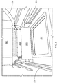
- FIG. 3 shows a perspective view of an interior portion of an embodiment of a 3D printing system 400 such as those shown schematically in FIG. 1 and FIG. 2 .
- a powder material feeder 405 and a first hopper 501
- a control system 505 a powder supply line 510 to the first hopper 501 and tracks 520 for translation of the powder material feeder 405 across the printing platform 407 are also visible.
- the powder material feeder 405 shown in FIG. 3 is referred to as a recorder.
- FIG. 4 shows a perspective view of an embodiment of a first hopper 501, such as the first hopper shown in FIG. 1 and FIG. 2 .
- the control system 505 below the powder chamber of the first hopper 501 selectively permits the material of the first powder material cut 301 to leave the first hopper 501 and go into the powder material feeder 405.
- the 3D printing process may alternatively be performed with a 3D printing system 400, where the powder deposition assembly 500 includes a first hopper 501, a second hopper 502, and a powder delivery assembly 401, as shown in FIG. 5 .
- the powder delivery assembly 401 includes at least one powder material feeder 405 supplied with a first powder material cut 301 from the first hopper 501 or supplied with a second powder material cut 302 from the second hopper 502, and at least one spreader 530 spreading the material of the first powder material cut 301 or the second powder material cut 302 on the surface 406 as a layer across the top of the powder bed above the printing platform 407 as a new layer to be sintered or melted.
- At least one valve 450 selectively controls whether the first powder material cut 301, the second powder material cut 302, or no powder material is fed to the surface 406.
- the spreader 530 may be any device capable of moving powder material across the surface 406 to form a layer above the printing platform 407.
- the spreaders 530 are rollers.
- the spreaders 530 are blades.
- the powder material feeders 405 are shown as depositing powder material on either side of the printing platform 407, the first powder material cut 301 and the second powder material cut 302 may alternatively be deposited on the same side of the printing platform 407 or directly above the printing platform 407.
- the 3D printing process includes a focused energy source 310 to fuse powder plastic, powder metal, powder ceramic, or powder glass to form the article 200.
- the focused energy source 310 is a high power laser.
- the high power laser is a carbon dioxide laser.
- the focused energy beam 409 is a pulsed beam.
- the focused energy beam 409 is directed by a scanner 320 to selectively fuse powder material by scanning cross-sections generated from a 3D digital description, such as, for example, a CAD file or scan data, of the article 200 on the surface 406 of a powder bed on a printing platform 407.
- the powder bed is lowered by one layer thickness by actuating a fabrication piston 420 to lower the printing platform 407, the first powder material cut 301 from the first hopper 501 or the second powder material cut 302 from the second hopper 502 is directed onto the surface 406 in an amount of material that is about the equivalent of one layer thickness of the powder bed, and the spreader 530 applies the new material as a new layer on top of the powder bed by the spreader 530. The process is repeated until the article 200 is completed.
- the article 200 being constructed is surrounded by un-sintered powder material at all times, which allows for the construction of previously-impossible geometries.
- the article 200 being formed in FIG. 5 includes two first portions 210 having a first layer thickness based on a first feature resolution separated by a second portion 220 having a second layer thickness based on a second feature resolution.
- the second portion 220 includes a feature 230 having a high fidelity.
- FIG. 6 schematically shows a model of an article 200 having a tubular geometry.
- the article 200 includes two first portions 210 having a first layer thickness based on a first feature resolution separated by a second portion 220 having a second layer thickness based on a second feature resolution.
- the second portion 220 includes at least one feature 230 having a high fidelity.
- the first layer thickness is about 50 ⁇ m (2 mil) and the second layer thickness is about 20 ⁇ m (0.8 mil).
- FIG. 7 shows a photograph of multiple articles 200 formed by 3D printing by a system disclosed herein.
- the articles 200 have a cylindrical geometry and include two first portions 210 having a first metal layer thickness based on a first feature resolution separated by a second portion 220 having a second metal layer thickness based on a second feature resolution.
- the first layer thickness is about 50 ⁇ m (2 mil) and the second layer thickness is about 20 ⁇ m (0.8 mil).
- the first portions 210 have a different surface appearance than the second portion 220, resulting from a greater surface roughness for the first portions 210, with both portions 210, 220 having a different surface texture and appearance than a machined surface.
- FIG. 8 shows an enlarged photograph of a feature 230 having a high fidelity in the second portion 220 with the second layer thickness.
- the feature 230 formed with a 20- ⁇ m (0.8 mil) build layer thickness has a higher feature fidelity than a feature formed with a 50- ⁇ m (2 mil) build layer thickness.
- movement of the printing platform 407 and/or the powder deposition assembly 500 of the 3D printing system 400 is controlled by software configured to automate the process and/or form the added material on the article 200 based upon a CAD model.
- the process is an automated 3D printing process.
- the relative movement of the printing platform 407 and/or the powder deposition assembly 500 provides a dimensional accuracy of at least +/- 25 ⁇ m (+/- 1 mil).
- Feedback sensors 350 evaluate the precision of the article 200 by measuring the actual dimensions of the deposited layers in comparison to the dimensions of the layer of the article 200 from the 3D CAD model.
- the powder material is a powder metal and the 3D printing is metal 3D printing.
- the powder metal is a high-temperature superalloy.
- the powder metal is an aluminum-based alloy, a titanium-based alloy, a steel-based alloy, a nickel-based superalloy, or a cobalt-based superalloy.
- the powder material is a powder ceramic and the 3D printing is ceramic 3D printing.
- the composition of the powder ceramic may include, but is not limited to, zirconia, silica, and alumina.
- the method of manufacturing the article 200 may be by any additive manufacturing method or technique including melting or sintering layers of a powder material.
- the 3D printing includes selective laser sintering (SLS), direct metal laser sintering (DMLS), selective laser melting (SLM), direct metal laser melting (DMLM), electron beam melting (EBM), powder bed processing, or combinations thereof.
- the 3D printing includes SLS with a powder bed.
- the SLS process includes a focused energy source 310 to fuse powder plastic, powder metal, powder ceramic, or powder glass to form the article 200.
- the focused energy source 310 is a high power laser.
- the high power laser is a carbon dioxide laser.
- the focused energy beam 409 is a pulsed beam. The focused energy beam 409 selectively fuses powder material by scanning cross-sections generated from a 3D digital description, such as, for example, a CAD file or scan data, of the article 200 on the surface 406 of a powder bed on a printing platform 407. After each cross-section is scanned, the powder bed is lowered by one layer thickness by lowering the printing platform 407, a new layer of powder material is applied on top, and the process is repeated until the article 200 is completed.
- the DMLS process includes a focused energy source 310 firing into a bed of powder metal.
- the focused energy source 310 is a ytterbium (Yb)-fiber laser, or more specifically a high-power 200-watt Yb-fiber optic laser.
- the focused energy source 310 is automatically fired at points in space defined by a 3D CAD model to heat the powder metal and sinter it to the article 200 being formed.
- computer software on a computer directs the focused energy source 310.
- the powder delivery assembly 401 includes a material dispensing platform dispensing the powder metal to a printing platform 407 and a recoater blade as the spreader 530 moving new powder material over the printing platform 407.
- the article 200 is built up additively, layer by layer. In some embodiments, the layers of the added material are about 20 micrometers thick.
- the DMLM process is performed with a powder delivery assembly 401 including one or more powder material feeders 405.
- the powder material feeders 405 selectively deliver the powder material and/or any other material directly as a new layer on the powder bed above the printing platform 407 or alternatively to the surface 406, where at least one spreader 530 directs the powder material toward the printing platform 407.
- the relative movement of the printing platform 407 and/or the scanner 320 during the DMLM process may provide a dimensional accuracy of at least 25 ⁇ m (1 mil), at least 130 ⁇ m (5 mil), at least 250 ⁇ m (10 mil), between 25 ⁇ m and 250 ⁇ m (1 and 10 mil), between 25 ⁇ m and 130 ⁇ m (1 and 5 mil), or any combination, sub-combination, range, or sub-range thereof. Additionally, the DMLM process provides a fully dense metal in the article 200 formed therefrom.
- Suitable focused energy sources 310 for the DMLM process include any focused energy source 310 operating in a power range and travel speed for melting a layer of the first powder material cut 301 or the second powder material cut 302 on the powder bed.
- the focused energy source 310 is a laser.
- the power range of the focused energy source 310 in the DMLM process includes, but is not limited to, between 100 and 3,000 watts, between 200 and 2,500 watts, between 300 and 2,000 watts, or any combination, sub-combination, range, or sub-range thereof.
- the travel speed includes, but is not limited to, up to 300 mm/sec, between 1 and 300 mm/sec, between 4 and 250 mm/sec, or any combination, sub-combination, range, or sub-range thereof.
- the focused energy source 310 operates in the power range of between 300 and 2,000 watts, at a travel speed of between 4 and 250 mm/sec.
- a deposition rate for standard steels, titanium, and/or nickel alloys includes, for example, up to 1 kg/hour, up to 0.75 kg/hr, up to 0.5 kg/hour, between 0.1 and 0.5 kg/hour, up to 0.4 kg/hour, up to 0.3 kg/hour, or any combination, sub-combination, range, or sub-range thereof.
- the parameters of the focused energy source 310 and the deposition rate may be adjusted and/or set depending on whether the first powder material cut 301 or the second powder material cut 302 is being supplied and/or on the layer thickness.
- the directing of the focused energy beam 409 includes moving the scanner 320 and/or the printing platform 407 relative to each other, the moving providing the shape and geometry of the added material on the article 200.
- the printing platform 407 may be fixed and the scanner 320 may be adjusted, the scanner 320 may be fixed and the printing platform 407 may be moved, or both the scanner 320 and the printing platform 407 may be adjusted independently of each other.
- the printing platform 407 includes three or more axes of rotation for moving relative to the scanner 320.
- the SLM process includes 3D CAD data as a digital information source and a focused energy source 310.
- the focused energy source 310 is a high-power (hundreds of watts) laser, and more specifically a Yb-fiber laser.
- the focused energy beam 409 melts a fine powder material to build the article 200.
- the powder material is added layer-by-layer, the layers usually being about 20 ⁇ m to 100 ⁇ m (0.8 to 4 mil) in thickness.
- the focused energy beam 409 selectively melts thin layers of atomized fine powder material that are evenly distributed by a powder material feeder 405 onto the article 200 being formed. This occurs in a controlled inert-gas chamber.
- the inert gas is typically either argon or nitrogen with oxygen levels below 500 parts per million.
- the focused energy source 310 energy is intense enough to permit full melting of the powder material particles.
- the EBM process is similar to the SLM process, but an electron beam is used as the focused energy beam 409 rather than a laser beam.
- the EBM process may operate at higher temperatures, such as, for example, up to 1000 °C (1830 °F), and has the capability for higher pre-heats.
- the powder bed process includes a focused energy source 310 to fuse (e.g., sinter or melt) a powder material.
- the powder bed process builds up the added material 200 layer by layer from fine powders, typically about 5 ⁇ m to 50 ⁇ m (0.2 to 2 mil) in size.
- a powder bed system typically includes a powder supply, a printing platform 407, a powder delivery assembly 401 including a powder material feeder 405, a laser as the focused energy source 310, and a laser directing system.
- the powder material feeder 405 spreads a thin layer of powder material on the powder bed on the printing platform 407.
- the laser melts or sinters the powder material in locations where the build is to be made. The spreading and melting/sintering process is repeated as the article 200 is built layer-by-layer.
- the selective control permits switching between the formation of a first layer thickness from the first powder material cut 301 and the formation of a second layer thickness from the second powder material cut 302.
- each layer is formed with only one of the two powder material cuts 301, 302 to give a substantially uniform layer thickness.
- the first layer thickness and the second layer thickness are preferably in the range of about 10 ⁇ m to about 100 ⁇ m (0.4 mil to 4 mil).
- the first layer thickness may be at least about 40 ⁇ m (0.4 mil), alternatively in the range of about 40 ⁇ m to about 100 ⁇ m (2 mil to 4 mil), alternatively in the range of about 50 ⁇ m to about 80 ⁇ m (2 mil to 3.1 mil), alternatively in the range of about 50 ⁇ m to about 70 ⁇ m (0.4 mil to 2.8 mil), alternatively in the range of about 40 ⁇ m to about 60 ⁇ m (0.4 mil to 2.4 mil), or any range or sub-range therebetween.
- the second layer thickness may be less than or equal to about 25 (0.4 mil), alternatively in the range of about 10 ⁇ m to about 45 ⁇ m (0.4 mil to 1.8 mil), alternatively in the range of about 10 ⁇ m to about 35 ⁇ m (0.4 mil to 1.4 mil), alternatively in the range of about 10 ⁇ m to about 25 ⁇ m (0.4 mil to 1 mil), alternatively in the range of about 15 ⁇ m to about 25 ⁇ m (0.4 mil to 0.6 mil), or any range or sub-range therebetween.
- the 3D printing system includes two powder hoppers 501, 502 with two different powder sizes and distributions.
- the hopper 502 with powder metal having a finer size and distribution is preferably only used for very specific layers where high feature 230 fidelity is desired.
- These specific layers are preferably built at 20 ⁇ m (0.8 mil) or sub-20 ⁇ m (sub-0.8 mil) build layer thickness. All of the other build layers may have a thickness of 50 ⁇ m (2 mil) or higher as necessary or desirable.
- a single focused energy source 310 is used both for layers of the first powder material cut 301 and for layers of the second powder material cut 302.
- the parameters of the focused energy source 310 and the deposition rate may be adjusted and/or set depending on whether the first powder material cut 301 or the second powder material cut 302 is being supplied and/or on the layer thickness.
- the first powder material cut 301 is preferably used to quickly build first portions 210 of the article 200, whereas the second powder material cut 302 is used to build second portions 220 of the article 200 where higher resolution is desired.
- the 3D printing system 400 is arranged and operates in a manner similar to the SLM 280 HL model selective laser melting system (SLM Solutions GmbH, Lübeck, Germany), except that the 3D printing system 400 includes two hoppers 501, 502 holding two different powder cuts 301, 302 and one, at least one, or two powder material feeders 405 to selectively supply powder material from the two hoppers 501, 502.
- the 3D printing system 400 includes up to a 280 mm by 280 mm by 365 build envelope, up to two fiber lasers with 3D scanning optics, a build rate of up to 55 cm 3 /hr, or combinations thereof.
- the 3D printing system 400 with two hoppers 501, 502 holding two different powder cuts 301, 302 and distributions permits variable build layer thickness and enables features 230 with finer fidelity. Larger powder size results in larger variations, making features 230 requiring 25 ⁇ m (+/- 1 mil) tolerances impossible, since the powder diameter itself is close to 50 ⁇ m (2 mil). Lower tolerance is achieved by using a smaller build layer thickness and corresponding smaller powder particle size. Better fidelity of features 230 without compromising build rate is achieved by having two hoppers 501, 502 supplying different powder material cuts 301, 302.
- the different powder material cuts 301, 302 may be of the same powder composition or different powder compositions.
- the article 200 may be any component requiring at least one feature 230 with high fidelity for at least a portion of the article 200.
- the article 200 is a hot gas path component of a turbine.
- the article 200 is a gas turbine seal, a gas turbine combustion component, such as, for example, a fuel nozzle, or a gas turbine hot gas path component, such as, for example, a gas turbine shroud, a gas turbine nozzle, or a gas turbine blade.
- high fidelity is achieved with features 230 that would otherwise be difficult or impossible to machine.
- fuel holes have very tight tolerances, and machining holes at difficult to reach locations is expensive.
- a high fidelity fuel hole in an as-built condition eliminates the machining problem and reduces manufacturing cost.
Landscapes
- Engineering & Computer Science (AREA)
- Manufacturing & Machinery (AREA)
- Chemical & Material Sciences (AREA)
- Materials Engineering (AREA)
- Mechanical Engineering (AREA)
- Physics & Mathematics (AREA)
- Optics & Photonics (AREA)
- Automation & Control Theory (AREA)
- Plasma & Fusion (AREA)
- Composite Materials (AREA)
- Ceramic Engineering (AREA)
- Powder Metallurgy (AREA)
- Producing Shaped Articles From Materials (AREA)
Abstract
Description
- The present embodiments are directed to methods, systems, and articles achieving high feature fidelity. More specifically, the present embodiments achieve high feature fidelity articles by additive manufacturing without subsequent machining.
- Three-dimensional (3D) printing is an additive manufacturing technique enabling creation of an article by forming successive layers of material under computer control to create a 3D structure. The process typically includes selectively heating portions of a layer of powder of the material to melt or sinter the powder to the previously-placed layers to form the article layer by layer. Plastic, ceramic, glass, and metal articles may be formed by 3D printing from powders of plastic, ceramic, glass, and metal, respectively. A 3D printer lays down powder material, and a focused energy source melts or sinters that powder material in certain predetermined locations based on a model from a computer-aided design (CAD) file. Heating methods include direct metal laser melting (DMLM), direct metal laser sintering (DMLS), selective laser melting (SLM), selective laser sintering (SLS), and electron beam melting (EBM). Once one layer is melted or sintered and formed, the 3D printer repeats the process by placing additional layers of material on top of the first layer or where otherwise instructed, one layer at a time, until the entire article is fabricated. 3D printing may be accomplished by powder bed processing or other methods of powder processing.
- Metal 3D printing enables manufacturers to create end-use metal articles that often outperform those produced with traditional casting techniques. Once those articles are installed for end-use, they continue to save money because of their light weight, high strength, and precise fit. In conventional article manufacturing, however, achieving high feature fidelity in an article formed by 3D printing may be difficult, if not impossible, without machining the article after formation by printing. For metal articles having features with tolerances in the range of +/- 25 µm (+/- 1.0 mil), it is not conventionally possible to achieve such high feature fidelity by metal 3D printing alone. The current lower limit is about 76 µm (3.0 mil). In the current conventional metal 3D printers, a single powder hopper and a single powder cut (powder size distribution) is used. A conventional metal powder cut for DMLM has an average particle size of about 30 µm (about 1.2 mil), with the particle size distribution being in the range of about 10 µm to about 45 µm (about 0.4 to about 1.8 mil). Such metal powder cuts are appropriate for build layer thicknesses of about 50 µm (2.0 mil) or greater. In order to achieve tolerances below about 76 µm (3.0 mil) with such build layers, a machining step is required after the metal 3D printing.
- Conventional ceramic powder cuts have an average particle size and a particle size distribution similar to conventional metal powder cuts.
- In an embodiment, a method of additively manufacturing an article includes forming a first portion of the article by three-dimensional printing of a plurality of first layers from a first powder material cut having a first average particle size corresponding to a first feature resolution. The first layers have a first average layer thickness. The method also includes forming a second portion of the article by three-dimensional printing of a plurality of second layers from a second powder material cut having a second average particle size corresponding to a second feature resolution less than the first feature resolution. The second portion includes at least one feature. The second layers have a second average layer thickness less than the first average layer thickness.
- In another embodiment, a three-dimensional printing system includes a printing platform, a powder deposition assembly, and a focused energy source. The powder deposition assembly is configured to controllably and selectively provide a first powder material cut having a first average particle size corresponding to a first feature resolution or a second powder material cut having a second average particle size corresponding to a second feature resolution to the printing platform. The second average particle size is less than the first average particle size. The focused energy source is configured to supply heating energy to powder material on the printing platform.
- In another embodiment, an article includes a first portion including a plurality of first layers from a first powder material cut having a first average particle size corresponding to a first feature resolution. The first layers have a first average layer thickness. The article also includes a second portion including a plurality of second layers from a second powder material cut having a second average particle size corresponding to a second feature resolution less than the first feature resolution. The second portion includes at least one feature. The second layers have a second average layer thickness less than the first average layer thickness.
- Other features and advantages of the present invention will be apparent from the following more detailed description, taken in conjunction with the accompanying drawings which illustrate, by way of example, the principles of the invention.
-
-
FIG. 1 is a schematic view of a three-dimensional (3D) printing system in an embodiment of the present disclosure. -
FIG. 2 is a schematic view of another 3D printing system in an embodiment of the present disclosure. -
FIG. 3 is a schematic perspective view showing the printing platform, a hopper, and a powder delivery assembly of the embodiments ofFIG. 1 andFIG. 2 . -
FIG. 4 is a schematic perspective view of the powder delivery assembly ofFIG. 3 . -
FIG. 5 is a schematic view of another 3D printing system in an embodiment of the present disclosure. -
FIG. 6 is a schematic view of a model for a 3D printed article in an embodiment of the present disclosure. -
FIG. 7 is a photograph of 3D metal printed articles based on a model similar to the model ofFIG. 6 in an embodiment of the present disclosure. -
FIG. 8 is a photograph showing a feature formed in one of the articles ofFIG. 7 . - Wherever possible, the same reference numbers will be used throughout the drawings to represent the same parts.
- Provided are methods, systems, and articles achieving high feature fidelity by additive manufacturing without subsequent machining.
- Embodiments of the present disclosure, for example, in comparison to concepts failing to include one or more of the features disclosed herein, achieve higher feature fidelity by additive manufacturing, achieve high feature fidelity by additive manufacturing without subsequent machining, eliminate machining in high feature fidelity formation, reduce manufacturing time for formation of high feature fidelity articles, reduce manufacturing cost for high feature fidelity articles, or combinations thereof.
- As used herein, "high fidelity" or "high feature fidelity" refers to a feature of an article having a tolerance less than a tolerance of a conventional three-dimensional (3D) printed article, which is, for example, about 76 µm (3.0 mil) for metals. In some embodiments, the high fidelity feature has a tolerance of 70 µm (2.8 mil), alternatively 65 µm (2.6 mil), alternatively 60 µm (2.4 mil), alternatively 55 µm (2.2 mil), alternatively 50 µm (2.0 mil), alternatively 45 µm (1.8 mil), alternatively 40 µm (1.6 mil), alternatively 35 µm (1.4 mil), alternatively 30 µm (1.2 mil), alternatively 25 µm (1.0 mil), alternatively 20 µm (0.8 mil), or any value therebetween.
- In some embodiments, the high fidelity feature is formed from a powder cut having an average particle size of about 25 µm (about 1.0 mil), alternatively about 20 µm (about 0.8 mil), alternatively about 15 µm (about 0.6 mil), alternatively about 10 µm (about 0.4 mil), or any value therebetween.
- In some embodiments, the high fidelity feature is formed from a powder cut having a particle size distribution in the range of about 10 µm to about 40 µm (about 0.4 mil to about 1.6 mil), alternatively in the range of about 10 µm to about 35 µm (about 0.4 mil to about 1.4 mil), alternatively in the range of about 10 µm to about 30 µm (about 0.4 mil to about 1.2 mil), alternatively in the range of about 10 µm to about 25 µm (about 0.4 mil to about 1.0 mil), alternatively in the range of about 10 µm to about 20 µm (about 0.4 mil to about 0.8 mil), alternatively in the range of about 5 µm to about 15 µm (about 0.2 mil to about 0.6 mil), or any range or sub-range therebetween.
- In some embodiments, the high fidelity feature is formed from a build layer thickness of about 45 µm (about 1.8 mil), alternatively about 40 µm (about 1.6 mil), alternatively about 35 µm (about 1.4 mil), alternatively about 30 µm (about 1.2 mil), alternatively about 25 µm (about 1.0 mil), alternatively about 20 µm (about 0.8 mil), or any value therebetween.
- Referring to
FIG. 1 , the additive manufacturing process may be performed with a3D printing system 400, where thepowder deposition assembly 500 includes afirst hopper 501, asecond hopper 502, apowder delivery assembly 401, and afocused energy source 310. Thepowder delivery assembly 401 includes at least onepowder material feeder 405 supplied with a first powder material cut 301 from thefirst hopper 501 or supplied with a second powder material cut 302 from thesecond hopper 502. The powder material feeder 405 deposits and spreads the material of the first powder material cut 301 or the second powder material cut 302 across thesurface 406 of the powder bed above theprinting platform 407 as a new layer to be sintered or melted. Thehoppers powder material feeders 405 during deposition of the new layer or thehoppers 3D printing system 400. Although twopowder material feeders 405 are shown inFIG. 1 , one for eachhopper powder material feeder 405 may alternatively be used for bothhoppers FIG. 2 , since only one powder cut 301, 302 is delivered at a time. - The
3D printing system 400 includes a focusedenergy source 310 to fuse powder plastic, powder metal, powder ceramic, or powder glass to form thearticle 200. In some embodiments, thefocused energy source 310 is a high power laser. In some embodiments, the high power laser is a carbon dioxide laser. In some embodiments, thefocused energy beam 409 is a pulsed beam. The focusedenergy beam 409 is directed by ascanner 320 to selectively fuse powder material by scanning cross-sections generated from a 3D digital description, such as, for example, a CAD file or scan data, of thearticle 200 on the surface of a powder bed on aprinting platform 407. Before each cross-section is scanned, the powder bed is lowered by one layer thickness by actuating afabrication piston 420 to lower theprinting platform 407 and one of thepowder material feeders 405 is actuated to deposit the material of the first powder material cut 301 from thefirst hopper 501 or to deposit the material of the second powder material cut 302 from thesecond hopper 502 as a new layer of powder material on top of the powder bed. The process is repeated until thearticle 200 is completed. - The
article 200 being constructed is surrounded by un-sintered powder material at all times, which allows for the construction of previously-impossible geometries. Thearticles 200 being formed inFIG. 1 andFIG. 2 include twofirst portions 210 having a first layer thickness based on a first feature resolution separated by asecond portion 220 having a second layer thickness based on a second feature resolution. Thesecond portion 220 includes afeature 230 having a high fidelity. -
FIG. 3 shows a perspective view of an interior portion of an embodiment of a3D printing system 400 such as those shown schematically inFIG. 1 andFIG. 2 . In addition to aprinting platform 407, apowder material feeder 405, and afirst hopper 501, acontrol system 505, apowder supply line 510 to thefirst hopper 501 andtracks 520 for translation of thepowder material feeder 405 across theprinting platform 407 are also visible. In some embodiments, thepowder material feeder 405 shown inFIG. 3 is referred to as a recorder. -
FIG. 4 shows a perspective view of an embodiment of afirst hopper 501, such as the first hopper shown inFIG. 1 andFIG. 2 . Thecontrol system 505 below the powder chamber of thefirst hopper 501 selectively permits the material of the first powder material cut 301 to leave thefirst hopper 501 and go into thepowder material feeder 405. - The 3D printing process may alternatively be performed with a
3D printing system 400, where thepowder deposition assembly 500 includes afirst hopper 501, asecond hopper 502, and apowder delivery assembly 401, as shown inFIG. 5 . Thepowder delivery assembly 401 includes at least onepowder material feeder 405 supplied with a first powder material cut 301 from thefirst hopper 501 or supplied with a second powder material cut 302 from thesecond hopper 502, and at least onespreader 530 spreading the material of the first powder material cut 301 or the second powder material cut 302 on thesurface 406 as a layer across the top of the powder bed above theprinting platform 407 as a new layer to be sintered or melted. At least onevalve 450 selectively controls whether the firstpowder material cut 301, the secondpowder material cut 302, or no powder material is fed to thesurface 406. - Although two
powder material feeders 405, twovalves 450, and twospreaders 530 are shown inFIG. 5 , one for eachhopper powder material feeder 405, asingle valve 450, and/or asingle spreader 530 may alternatively be used for bothhoppers powder cut surface 406 at a time. Thespreader 530 may be any device capable of moving powder material across thesurface 406 to form a layer above theprinting platform 407. In some embodiments, thespreaders 530 are rollers. In some embodiments, thespreaders 530 are blades. Although thepowder material feeders 405 are shown as depositing powder material on either side of theprinting platform 407, the firstpowder material cut 301 and the second powder material cut 302 may alternatively be deposited on the same side of theprinting platform 407 or directly above theprinting platform 407. - The 3D printing process includes a focused
energy source 310 to fuse powder plastic, powder metal, powder ceramic, or powder glass to form thearticle 200. In some embodiments, the focusedenergy source 310 is a high power laser. In some embodiments, the high power laser is a carbon dioxide laser. In some embodiments, thefocused energy beam 409 is a pulsed beam. Thefocused energy beam 409 is directed by ascanner 320 to selectively fuse powder material by scanning cross-sections generated from a 3D digital description, such as, for example, a CAD file or scan data, of thearticle 200 on thesurface 406 of a powder bed on aprinting platform 407. Before each cross-section is scanned, the powder bed is lowered by one layer thickness by actuating afabrication piston 420 to lower theprinting platform 407, the first powder material cut 301 from thefirst hopper 501 or the second powder material cut 302 from thesecond hopper 502 is directed onto thesurface 406 in an amount of material that is about the equivalent of one layer thickness of the powder bed, and thespreader 530 applies the new material as a new layer on top of the powder bed by thespreader 530. The process is repeated until thearticle 200 is completed. - The
article 200 being constructed is surrounded by un-sintered powder material at all times, which allows for the construction of previously-impossible geometries. Thearticle 200 being formed inFIG. 5 includes twofirst portions 210 having a first layer thickness based on a first feature resolution separated by asecond portion 220 having a second layer thickness based on a second feature resolution. Thesecond portion 220 includes afeature 230 having a high fidelity. -
FIG. 6 schematically shows a model of anarticle 200 having a tubular geometry. Thearticle 200 includes twofirst portions 210 having a first layer thickness based on a first feature resolution separated by asecond portion 220 having a second layer thickness based on a second feature resolution. Thesecond portion 220 includes at least onefeature 230 having a high fidelity. The first layer thickness is about 50 µm (2 mil) and the second layer thickness is about 20 µm (0.8 mil). -
FIG. 7 shows a photograph ofmultiple articles 200 formed by 3D printing by a system disclosed herein. Thearticles 200 have a cylindrical geometry and include twofirst portions 210 having a first metal layer thickness based on a first feature resolution separated by asecond portion 220 having a second metal layer thickness based on a second feature resolution. The first layer thickness is about 50 µm (2 mil) and the second layer thickness is about 20 µm (0.8 mil). As seen inFIG. 7 , thefirst portions 210 have a different surface appearance than thesecond portion 220, resulting from a greater surface roughness for thefirst portions 210, with bothportions -
FIG. 8 shows an enlarged photograph of afeature 230 having a high fidelity in thesecond portion 220 with the second layer thickness. Thefeature 230 formed with a 20-µm (0.8 mil) build layer thickness has a higher feature fidelity than a feature formed with a 50-µm (2 mil) build layer thickness. Being able to use different size and distribution powder material for the same build job significantly improves the capability of metal 3D printing as a stand-alone manufacturing process, even beyond what conventional metal 3D printing in combination with machine finishing is able to achieve in some cases. - In some embodiments, movement of the
printing platform 407 and/or thepowder deposition assembly 500 of the3D printing system 400 is controlled by software configured to automate the process and/or form the added material on thearticle 200 based upon a CAD model. In some embodiments, the process is an automated 3D printing process. In some embodiments, the relative movement of theprinting platform 407 and/or thepowder deposition assembly 500 provides a dimensional accuracy of at least +/- 25 µm (+/- 1 mil). Feedback sensors 350 evaluate the precision of thearticle 200 by measuring the actual dimensions of the deposited layers in comparison to the dimensions of the layer of thearticle 200 from the 3D CAD model. - In some embodiments, the powder material is a powder metal and the 3D printing is metal 3D printing. In some embodiments, the powder metal is a high-temperature superalloy. In some embodiments, the powder metal is an aluminum-based alloy, a titanium-based alloy, a steel-based alloy, a nickel-based superalloy, or a cobalt-based superalloy.
- In some embodiments, the powder material is a powder ceramic and the 3D printing is ceramic 3D printing. The composition of the powder ceramic may include, but is not limited to, zirconia, silica, and alumina.
- The method of manufacturing the
article 200 may be by any additive manufacturing method or technique including melting or sintering layers of a powder material. In some embodiments, the 3D printing includes selective laser sintering (SLS), direct metal laser sintering (DMLS), selective laser melting (SLM), direct metal laser melting (DMLM), electron beam melting (EBM), powder bed processing, or combinations thereof. In some embodiments, the 3D printing includes SLS with a powder bed. - In some embodiments, the SLS process includes a focused
energy source 310 to fuse powder plastic, powder metal, powder ceramic, or powder glass to form thearticle 200. In some embodiments, the focusedenergy source 310 is a high power laser. In some embodiments, the high power laser is a carbon dioxide laser. In some embodiments, thefocused energy beam 409 is a pulsed beam. Thefocused energy beam 409 selectively fuses powder material by scanning cross-sections generated from a 3D digital description, such as, for example, a CAD file or scan data, of thearticle 200 on thesurface 406 of a powder bed on aprinting platform 407. After each cross-section is scanned, the powder bed is lowered by one layer thickness by lowering theprinting platform 407, a new layer of powder material is applied on top, and the process is repeated until thearticle 200 is completed. - In some embodiments, the DMLS process includes a focused
energy source 310 firing into a bed of powder metal. In some embodiments, the focusedenergy source 310 is a ytterbium (Yb)-fiber laser, or more specifically a high-power 200-watt Yb-fiber optic laser. The focusedenergy source 310 is automatically fired at points in space defined by a 3D CAD model to heat the powder metal and sinter it to thearticle 200 being formed. In some embodiments, computer software on a computer directs the focusedenergy source 310. Inside a build chamber area, thepowder delivery assembly 401 includes a material dispensing platform dispensing the powder metal to aprinting platform 407 and a recoater blade as thespreader 530 moving new powder material over theprinting platform 407. Thearticle 200 is built up additively, layer by layer. In some embodiments, the layers of the added material are about 20 micrometers thick. - In some embodiments, the DMLM process is performed with a
powder delivery assembly 401 including one or morepowder material feeders 405. During the DMLM process, thepowder material feeders 405 selectively deliver the powder material and/or any other material directly as a new layer on the powder bed above theprinting platform 407 or alternatively to thesurface 406, where at least onespreader 530 directs the powder material toward theprinting platform 407. - The relative movement of the
printing platform 407 and/or thescanner 320 during the DMLM process may provide a dimensional accuracy of at least 25 µm (1 mil), at least 130 µm (5 mil), at least 250 µm (10 mil), between 25 µm and 250 µm (1 and 10 mil), between 25 µm and 130 µm (1 and 5 mil), or any combination, sub-combination, range, or sub-range thereof. Additionally, the DMLM process provides a fully dense metal in thearticle 200 formed therefrom. - Suitable
focused energy sources 310 for the DMLM process include anyfocused energy source 310 operating in a power range and travel speed for melting a layer of the first powder material cut 301 or the second powder material cut 302 on the powder bed. In some embodiments, the focusedenergy source 310 is a laser. In one embodiment, the power range of the focusedenergy source 310 in the DMLM process includes, but is not limited to, between 100 and 3,000 watts, between 200 and 2,500 watts, between 300 and 2,000 watts, or any combination, sub-combination, range, or sub-range thereof. In another embodiment, the travel speed includes, but is not limited to, up to 300 mm/sec, between 1 and 300 mm/sec, between 4 and 250 mm/sec, or any combination, sub-combination, range, or sub-range thereof. For example, in a further embodiment, the focusedenergy source 310 operates in the power range of between 300 and 2,000 watts, at a travel speed of between 4 and 250 mm/sec. In another embodiment, a deposition rate for standard steels, titanium, and/or nickel alloys includes, for example, up to 1 kg/hour, up to 0.75 kg/hr, up to 0.5 kg/hour, between 0.1 and 0.5 kg/hour, up to 0.4 kg/hour, up to 0.3 kg/hour, or any combination, sub-combination, range, or sub-range thereof. The parameters of the focusedenergy source 310 and the deposition rate, however, may be adjusted and/or set depending on whether the first powder material cut 301 or the second powder material cut 302 is being supplied and/or on the layer thickness. - In some embodiments, the directing of the
focused energy beam 409 includes moving thescanner 320 and/or theprinting platform 407 relative to each other, the moving providing the shape and geometry of the added material on thearticle 200. To provide relative movement, theprinting platform 407 may be fixed and thescanner 320 may be adjusted, thescanner 320 may be fixed and theprinting platform 407 may be moved, or both thescanner 320 and theprinting platform 407 may be adjusted independently of each other. For example, in one embodiment, theprinting platform 407 includes three or more axes of rotation for moving relative to thescanner 320. - In some embodiments, the SLM process includes 3D CAD data as a digital information source and a
focused energy source 310. In some embodiments, the focusedenergy source 310 is a high-power (hundreds of watts) laser, and more specifically a Yb-fiber laser. Thefocused energy beam 409 melts a fine powder material to build thearticle 200. The powder material is added layer-by-layer, the layers usually being about 20 µm to 100 µm (0.8 to 4 mil) in thickness. Thefocused energy beam 409 selectively melts thin layers of atomized fine powder material that are evenly distributed by apowder material feeder 405 onto thearticle 200 being formed. This occurs in a controlled inert-gas chamber. The inert gas is typically either argon or nitrogen with oxygen levels below 500 parts per million. The focusedenergy source 310 energy is intense enough to permit full melting of the powder material particles. - In some embodiments, the EBM process is similar to the SLM process, but an electron beam is used as the
focused energy beam 409 rather than a laser beam. The EBM process may operate at higher temperatures, such as, for example, up to 1000 °C (1830 °F), and has the capability for higher pre-heats. - In some embodiments, the powder bed process includes a focused
energy source 310 to fuse (e.g., sinter or melt) a powder material. The powder bed process builds up the addedmaterial 200 layer by layer from fine powders, typically about 5 µm to 50 µm (0.2 to 2 mil) in size. A powder bed system typically includes a powder supply, aprinting platform 407, apowder delivery assembly 401 including apowder material feeder 405, a laser as thefocused energy source 310, and a laser directing system. Thepowder material feeder 405 spreads a thin layer of powder material on the powder bed on theprinting platform 407. The laser melts or sinters the powder material in locations where the build is to be made. The spreading and melting/sintering process is repeated as thearticle 200 is built layer-by-layer. - The selective control permits switching between the formation of a first layer thickness from the first
powder material cut 301 and the formation of a second layer thickness from the secondpowder material cut 302. In some embodiments, each layer is formed with only one of the twopowder material cuts - A smaller build layer thickness and a smaller corresponding powder size and distribution are provided to achieve
greater feature 230 fidelity. In some embodiments, the 3D printing system includes twopowder hoppers hopper 502 with powder metal having a finer size and distribution is preferably only used for very specific layers wherehigh feature 230 fidelity is desired. These specific layers are preferably built at 20 µm (0.8 mil) or sub-20 µm (sub-0.8 mil) build layer thickness. All of the other build layers may have a thickness of 50 µm (2 mil) or higher as necessary or desirable. - In some embodiments, a single
focused energy source 310 is used both for layers of the firstpowder material cut 301 and for layers of the secondpowder material cut 302. The parameters of the focusedenergy source 310 and the deposition rate, however, may be adjusted and/or set depending on whether the first powder material cut 301 or the second powder material cut 302 is being supplied and/or on the layer thickness. The first powder material cut 301 is preferably used to quickly buildfirst portions 210 of thearticle 200, whereas the second powder material cut 302 is used to buildsecond portions 220 of thearticle 200 where higher resolution is desired. - In some embodiments, the
3D printing system 400 is arranged and operates in a manner similar to the SLM 280 HL model selective laser melting system (SLM Solutions GmbH, Lübeck, Germany), except that the3D printing system 400 includes twohoppers different powder cuts powder material feeders 405 to selectively supply powder material from the twohoppers 3D printing system 400 includes up to a 280 mm by 280 mm by 365 build envelope, up to two fiber lasers with 3D scanning optics, a build rate of up to 55 cm3/hr, or combinations thereof. - The
3D printing system 400 with twohoppers different powder cuts features 230 with finer fidelity. Larger powder size results in larger variations, makingfeatures 230 requiring 25 µm (+/- 1 mil) tolerances impossible, since the powder diameter itself is close to 50 µm (2 mil). Lower tolerance is achieved by using a smaller build layer thickness and corresponding smaller powder particle size. Better fidelity offeatures 230 without compromising build rate is achieved by having twohoppers powder material cuts powder material cuts - The
article 200 may be any component requiring at least onefeature 230 with high fidelity for at least a portion of thearticle 200. In some embodiments, thearticle 200 is a hot gas path component of a turbine. In some embodiments, thearticle 200 is a gas turbine seal, a gas turbine combustion component, such as, for example, a fuel nozzle, or a gas turbine hot gas path component, such as, for example, a gas turbine shroud, a gas turbine nozzle, or a gas turbine blade. - In some embodiments, high fidelity is achieved with
features 230 that would otherwise be difficult or impossible to machine. For example, fuel holes have very tight tolerances, and machining holes at difficult to reach locations is expensive. A high fidelity fuel hole in an as-built condition eliminates the machining problem and reduces manufacturing cost. - While the invention has been described with reference to one or more embodiments, it will be understood by those skilled in the art that various changes may be made and equivalents may be substituted for elements thereof without departing from the scope of the invention. In addition, many modifications may be made to adapt a particular situation or material to the teachings of the invention without departing from the essential scope thereof. Therefore, it is intended that the invention not be limited to the particular embodiment disclosed as the best mode contemplated for carrying out this invention, but that the invention will include all embodiments falling within the scope of the appended claims. In addition, all numerical values identified in the detailed description shall be interpreted as though the precise and approximate values are both expressly identified.
- Various aspects and embodiments of the present invention are defined by the following clauses:
- 1. A method of additively manufacturing an article comprising:
- forming a first portion of the article by three-dimensional printing of a plurality of first layers from a first powder material cut having a first average particle size corresponding to a first feature resolution, the plurality of first layers having a first average layer thickness; and
- forming a second portion of the article by three-dimensional printing of a plurality of second layers from a second powder material cut having a second average particle size corresponding to a second feature resolution less than the first feature resolution, the second portion comprising at least one feature, the plurality of second layers having a second average layer thickness less than the first average layer thickness.
- 2. The method of clause 1, wherein forming the first portion and forming the second portion comprise powder bed processing and a technique selected from the group consisting of direct metal laser melting, direct metal laser sintering, selective laser melting, selective laser sintering, electron beam melting, and combinations thereof.
- 3. The method of clause 1, wherein the first average layer thickness is at least 40 µm.
- 4. The method of clause 1, wherein the second average layer thickness is less than or equal to 25 µm.
- 5. The method of clause 1, wherein the at least one feature includes a surface feature having a tolerance less than 50 µm.
- 6. The method of clause 1 further comprising providing the article free from machining after forming the first portion and the second portion by the three-dimensional printing.
- 7. The method of clause 1, wherein the first powder material cut and the second powder material cut comprise a powder material selected from the group consisting of a ceramic, a high-temperature superalloy, an aluminum-based alloy, a titanium-based alloy, a steel-based alloy, a nickel-based superalloy, a cobalt-based superalloy, and combinations thereof.
- 8. A three-dimensional printing system comprising:
- a printing platform;
- a powder deposition assembly configured to controllably and selectively provide a first powder material cut having a first average particle size corresponding to a first feature resolution or a second powder material cut having a second average particle size corresponding to a second feature resolution to the printing platform, the second average particle size being less than the first average particle size; and
- a focused energy source configured to supply heating energy to powder material on the printing platform.
- 9. The three-dimensional printing system of clause 8, wherein the powder deposition assembly comprises:
- a first hopper storing the first powder material cut having the first average particle size;
- a second hopper storing the second powder material cut having the second average particle size; and
- a powder delivery assembly selectively delivering the first powder material cut from the first hopper to the printing platform or the second powder material cut from the second hopper to the printing platform.
- 10. The three-dimensional printing system of clause 8 further comprising a control system directing the heating energy based on a computer model of an article being formed by the three-dimensional printing system.
- 11. The three-dimensional printing system of clause 8, wherein the focused energy source is selected from the group consisting of a laser and an electron beam generator.
- 12. The three-dimensional printing system of clause 8, wherein the first average particle size is at least 45 µm.
- 13. The three-dimensional printing system of clause 8, wherein the second average particle size is less than 25 µm.
- 14. The three-dimensional printing system of clause 8, wherein the first powder material cut and the second powder material cut comprise a powder material selected from the group consisting of a ceramic, a high-temperature superalloy, an aluminum-based alloy, a titanium-based alloy, a steel-based alloy, a nickel-based superalloy, a cobalt-based superalloy, and combinations thereof.
- 15. An article formed from a powder material by three-dimensional printing, the article comprising:
- a first portion comprising a plurality of first layers from a first powder material cut having a first average particle size corresponding to a first feature resolution, the plurality of first layers having a first average layer thickness; and
- a second portion comprising a plurality of second layers from a second powder material cut having a second average particle size corresponding to a second feature resolution less than the first feature resolution, the second portion comprising at least one feature, the plurality of second layers having a second average layer thickness less than the first average layer thickness.
- 16. The article of clause 15, wherein the first powder material cut and the second powder material cut comprise a powder material selected from the group consisting of a ceramic, a high-temperature superalloy, an aluminum-based alloy, a titanium-based alloy, a steel-based alloy, a nickel-based superalloy, a cobalt-based superalloy, and combinations thereof.
- 17. The article of clause 15, wherein the article is free from any machining after being formed by the three-dimensional printing.
- 18. The article of clause 15, wherein the first average layer thickness is at least 40 µm.
- 19. The article of clause 15, wherein the second average layer thickness is less than or equal to 25 µm.
- 20. The article of clause 15, wherein the at least one feature includes a surface feature having a tolerance less than 50 µm.
Claims (15)
- A method of additively manufacturing an article (100) comprising:forming a first portion (210) of the article (100) by three-dimensional printing of a plurality of first layers from a first powder material cut (301) having a first average particle size corresponding to a first feature resolution, the plurality of first layers having a first average layer thickness; andforming a second portion (220) of the article (100) by three-dimensional printing of a plurality of second layers from a second powder material cut (302) having a second average particle size corresponding to a second feature resolution less than the first feature resolution, the second portion (220) comprising at least one feature (230), the plurality of second layers having a second average layer thickness less than the first average layer thickness.
- The method of claim 1, wherein forming the first portion (210) and forming the second portion (220) comprise powder bed processing and a technique selected from the group consisting of direct metal laser melting, direct metal laser sintering, selective laser melting, selective laser sintering, electron beam melting, and combinations thereof.
- The method of claim 1 or 2, wherein the first average layer thickness is at least 40 µm.
- The method of any one of claims 1 to 3, wherein the second average layer thickness is less than or equal to 25 µm.
- The method of any one of claims 1 to 4, wherein the at least one feature (230) includes a surface feature having a tolerance less than 50 µm.
- The method of any one of claims 1 to 5 further comprising providing the article free from machining after forming the first portion (210) and the second portion (220) by the three-dimensional printing.
- A three-dimensional printing system (400) comprising:a printing platform (407);a powder deposition assembly (500) configured to controllably and selectively provide a first powder material cut (301) having a first average particle size corresponding to a first feature resolution or a second powder material cut (302) having a second average particle size corresponding to a second feature resolution to the printing platform (407), the second average particle size being less than the first average particle size; anda focused energy source (310) configured to supply heating energy to powder material on the printing platform (407).
- The three-dimensional printing system (400) of claim 7, wherein the powder deposition assembly (500) comprises:a first hopper (501) storing the first powder material cut (301) having the first average particle size;a second hopper (502) storing the second powder material cut (302) having the second average particle size; anda powder delivery assembly (401) selectively delivering the first powder material cut (301) from the first hopper (501) to the printing platform (407) or the second powder material cut (302) from the second hopper (502) to the printing platform (407).
- The three-dimensional printing system (400) of claim 7 or 8 further comprising a control system (505) directing the heating energy based on a computer model of an article (100) being formed by the three-dimensional printing system (400).
- An article (100) formed from a powder material by three-dimensional printing, the article (100) comprising:a first portion (210) comprising a plurality of first layers from a first powder material cut (301) having a first average particle size corresponding to a first feature resolution, the plurality of first layers having a first average layer thickness; anda second portion (220) comprising a plurality of second layers from a second powder material cut (302) having a second average particle size corresponding to a second feature resolution less than the first feature resolution, the second portion (220) comprising at least one feature (230), the plurality of second layers having a second average layer thickness less than the first average layer thickness.
- The article (100) of claim 10, wherein the first powder material cut (301) and the second powder material cut (302) comprise a powder material selected from the group consisting of a ceramic, a high-temperature superalloy, an aluminum-based alloy, a titanium-based alloy, a steel-based alloy, a nickel-based superalloy, a cobalt-based superalloy, and combinations thereof.
- The article (100) of claim 10 or 11, wherein the article (100) is free from any machining after being formed by the three-dimensional printing.
- The article (100) of any one of claims 10 to 12, wherein the first average layer thickness is at least 40 µm.
- The article (100) of any one of claims 10 to 13, wherein the second average layer thickness is less than or equal to 25 µm.
- The article (100) of any one of claims 10 to 14, wherein the at least one feature (230) includes a surface feature having a tolerance less than 50 µm.
Applications Claiming Priority (1)
| Application Number | Priority Date | Filing Date | Title |
|---|---|---|---|
| US15/420,939 US10773310B2 (en) | 2017-01-31 | 2017-01-31 | Additive manufacturing system, article, and method of manufacturing an article |
Publications (2)
| Publication Number | Publication Date |
|---|---|
| EP3354380A1 true EP3354380A1 (en) | 2018-08-01 |
| EP3354380B1 EP3354380B1 (en) | 2022-05-11 |
Family
ID=61027535
Family Applications (1)
| Application Number | Title | Priority Date | Filing Date |
|---|---|---|---|
| EP18153391.0A Active EP3354380B1 (en) | 2017-01-31 | 2018-01-25 | Additive manufacturing system, article, and method of manufacturing an article |
Country Status (3)
| Country | Link |
|---|---|
| US (1) | US10773310B2 (en) |
| EP (1) | EP3354380B1 (en) |
| JP (1) | JP7523880B2 (en) |
Families Citing this family (14)
| Publication number | Priority date | Publication date | Assignee | Title |
|---|---|---|---|---|
| EP3501726B1 (en) * | 2017-12-20 | 2020-08-05 | C.R.F. Società Consortile per Azioni | A method for applying a reinforcement of metal material to a component of metal material, particularly in the construction of a motor-vehicle body or a sub-assembly thereof |
| DE102018205820A1 (en) * | 2018-04-17 | 2019-10-17 | Eos Gmbh Electro Optical Systems | Selective re-exposure |
| US11426818B2 (en) | 2018-08-10 | 2022-08-30 | The Research Foundation for the State University | Additive manufacturing processes and additively manufactured products |
| KR102131402B1 (en) * | 2018-09-11 | 2020-07-08 | 주식회사 엠오피(M.O.P Co., Ltd.) | 3d printer and method for printing three dimensional structur using the same |
| US20200139621A1 (en) * | 2018-11-07 | 2020-05-07 | Ethicon Llc | 3d printed in-process powder capsule for printing material powder characterization |
| KR102161304B1 (en) * | 2018-11-26 | 2020-10-05 | 한국생산기술연구원 | Different Material Additive Manufacturing Apparatus with Multi Hopper And the Manufacturing Method thereof |
| US11331754B2 (en) * | 2018-11-26 | 2022-05-17 | The Boeing Company | Additive manufacturing apparatus and system with a part detachment assembly, and method of using the same |
| DE102019210487A1 (en) * | 2019-07-16 | 2021-03-25 | MTU Aero Engines AG | Layer construction method and layer construction device for the additive manufacture of at least one component area of a component as well as computer program product and storage medium |
| JP6993492B1 (en) * | 2020-10-20 | 2022-01-13 | 株式会社ソディック | Laminated modeling equipment |
| CN116710218A (en) * | 2020-12-14 | 2023-09-05 | 恩特格里斯公司 | Multilayer composite with different layer thicknesses and related method |
| JP2024506793A (en) * | 2021-02-22 | 2024-02-15 | エクサドン アーゲー | Method for making probe cards |
| CN114734060B (en) * | 2022-04-18 | 2024-06-14 | 深圳市华阳新材料科技有限公司 | Powder spreading printing method |
| US12330230B2 (en) | 2022-08-19 | 2025-06-17 | General Electric Company | Additively manufactured joined parts |
| WO2024240762A1 (en) * | 2023-05-23 | 2024-11-28 | Merck Patent Gmbh | Novel 3d printing concept for pharmaceutical dosage forms via selective laser sintering |
Citations (7)
| Publication number | Priority date | Publication date | Assignee | Title |
|---|---|---|---|---|
| US20130108726A1 (en) * | 2011-03-02 | 2013-05-02 | Bego Medical Gmbh | Device for the generative manufacturing of three-dimensional components |
| US20140099476A1 (en) * | 2012-10-08 | 2014-04-10 | Ramesh Subramanian | Additive manufacture of turbine component with multiple materials |
| US20140295087A1 (en) * | 2011-12-14 | 2014-10-02 | Alstom Technology Ltd | Method for additively manufacturing an article made of a difficult-to-weld material |
| US20150071809A1 (en) * | 2013-09-06 | 2015-03-12 | Arcam Ab | Powder distribution in additive manufacturing of three-dimensional articles |
| US20160090848A1 (en) * | 2013-06-18 | 2016-03-31 | Alstom Technology Ltd. | Method for producing a three-dimensional article and article produced with such a method |
| US20160214211A1 (en) * | 2013-10-09 | 2016-07-28 | United Technologies Corporation | Multi-density, multi-property turbine component |
| US20160303656A1 (en) * | 2015-04-16 | 2016-10-20 | General Electric Company | Article and method of forming an article |
Family Cites Families (27)
| Publication number | Priority date | Publication date | Assignee | Title |
|---|---|---|---|---|
| WO2004096469A1 (en) * | 2003-04-29 | 2004-11-11 | National University Of Singapore | A metal powder composition |
| US6995334B1 (en) | 2003-08-25 | 2006-02-07 | Southern Methodist University | System and method for controlling the size of the molten pool in laser-based additive manufacturing |
| JP2006205456A (en) | 2005-01-26 | 2006-08-10 | Toyota Motor Corp | Powder supply equipment for powder additive manufacturing |
| DE102005050665A1 (en) * | 2005-10-20 | 2007-04-26 | Bego Medical Gmbh | Layer-wise production process with grain size influencing |
| JP5230264B2 (en) * | 2007-05-23 | 2013-07-10 | パナソニック株式会社 | Manufacturing method of three-dimensional shaped object |
| US20100008816A1 (en) * | 2008-07-11 | 2010-01-14 | Honeywell International Inc. | Nickel-based superalloys, repaired turbine engine components, and methods for repairing turbine components |
| CA2788249A1 (en) * | 2009-12-30 | 2011-07-07 | Beat Lechmann | Intergrated multi-material implants and methods of manufacture |
| CH705631A1 (en) | 2011-10-31 | 2013-05-15 | Alstom Technology Ltd | Components or coupon for use under high thermal load and voltage and method for producing such a component, or of such a coupon. |
| TWI472427B (en) * | 2012-01-20 | 2015-02-11 | 財團法人工業技術研究院 | Device and method for powder distribution and additive manufacturing method using the same |
| US20130287933A1 (en) * | 2012-04-25 | 2013-10-31 | Pierre J. Kaiser | Three-dimensional (3d) printing |
| US9126167B2 (en) | 2012-05-11 | 2015-09-08 | Arcam Ab | Powder distribution in additive manufacturing |
| US20140004462A1 (en) * | 2012-06-29 | 2014-01-02 | Mark Cameron Zaretsky | Making article with desired profile |
| FR2994113B1 (en) * | 2012-07-31 | 2017-10-06 | Michelin & Cie | MACHINE AND PROCESS FOR ADDITIVE MANUFACTURE OF POWDER |
| DK2892708T3 (en) | 2012-09-05 | 2019-01-28 | Aprecia Pharmaceuticals LLC | THREE-DIMENSIONAL PRESSURE SYSTEM AND EQUIPMENT |
| US10710161B2 (en) * | 2013-03-11 | 2020-07-14 | Raytheon Technologies Corporation | Turbine disk fabrication with in situ material property variation |
| GB201316430D0 (en) * | 2013-09-16 | 2013-10-30 | Univ Nottingham | Additive manufacturing |
| EP3083084A4 (en) | 2013-12-18 | 2017-08-16 | United Technologies Corporation | Powder classification system and method |
| US10052797B2 (en) | 2014-01-25 | 2018-08-21 | Made In Space, Inc. | Recycling materials in various environments including reduced gravity environments |
| US20150224607A1 (en) | 2014-02-07 | 2015-08-13 | Siemens Energy, Inc. | Superalloy solid freeform fabrication and repair with preforms of metal and flux |
| JP6466793B2 (en) * | 2015-07-10 | 2019-02-06 | 株式会社東芝 | Turbine component manufacturing method, turbine component, and turbine component manufacturing apparatus |
| EP3325191B1 (en) * | 2015-07-24 | 2020-09-30 | Hewlett-Packard Development Company, L.P. | Stabilizing liquid functional material for three-dimensional (3d) printing |
| US10226917B2 (en) * | 2015-07-27 | 2019-03-12 | Dmg Mori Seiki Usa | Powder delivery systems and methods for additive manufacturing apparatus |
| KR20180043303A (en) * | 2015-09-16 | 2018-04-27 | 어플라이드 머티어리얼스, 인코포레이티드 | Powder delivery for lamination |
| FR3044944B1 (en) * | 2015-12-14 | 2021-07-16 | Snecma | DEVICE AND METHOD FOR MANUFACTURING A THREE-DIMENSIONAL PART BY SELECTIVE FUSION ON A POWDER BED |
| EP3223299A4 (en) * | 2016-01-21 | 2018-04-18 | Technology Research Association for Future Additive Manufacturing | 3d-modeling device, 3d-modeling device control method and 3d-modeling device control program |
| EP3565713B1 (en) * | 2017-01-03 | 2023-06-07 | L3F Sweden AB | A method for printing a 3d product and a 3d printing device |
| EP3511163B1 (en) * | 2018-01-12 | 2024-03-20 | Concept Laser GmbH | Method for operating an apparatus for additively manufacturing of three-dimensional objects |
-
2017
- 2017-01-31 US US15/420,939 patent/US10773310B2/en active Active
-
2018
- 2018-01-18 JP JP2018006054A patent/JP7523880B2/en active Active
- 2018-01-25 EP EP18153391.0A patent/EP3354380B1/en active Active
Patent Citations (7)
| Publication number | Priority date | Publication date | Assignee | Title |
|---|---|---|---|---|
| US20130108726A1 (en) * | 2011-03-02 | 2013-05-02 | Bego Medical Gmbh | Device for the generative manufacturing of three-dimensional components |
| US20140295087A1 (en) * | 2011-12-14 | 2014-10-02 | Alstom Technology Ltd | Method for additively manufacturing an article made of a difficult-to-weld material |
| US20140099476A1 (en) * | 2012-10-08 | 2014-04-10 | Ramesh Subramanian | Additive manufacture of turbine component with multiple materials |
| US20160090848A1 (en) * | 2013-06-18 | 2016-03-31 | Alstom Technology Ltd. | Method for producing a three-dimensional article and article produced with such a method |
| US20150071809A1 (en) * | 2013-09-06 | 2015-03-12 | Arcam Ab | Powder distribution in additive manufacturing of three-dimensional articles |
| US20160214211A1 (en) * | 2013-10-09 | 2016-07-28 | United Technologies Corporation | Multi-density, multi-property turbine component |
| US20160303656A1 (en) * | 2015-04-16 | 2016-10-20 | General Electric Company | Article and method of forming an article |
Non-Patent Citations (2)
| Title |
|---|
| KARLSSON JOAKIM ET AL: "Characterization and comparison of materials produced by Electron Beam Melting (EBM) of two different Ti-6Al-4V powder f", JOURNAL OF MATERIALS PROCESSING TECHNOLOGY, vol. 213, no. 12, 20 June 2013 (2013-06-20), pages 2109 - 2118, XP028711845, ISSN: 0924-0136, DOI: 10.1016/J.JMATPROTEC.2013.06.010 * |
| SONG BO ET AL: "Differences in microstructure and properties between selective laser melting and traditional manufacturing for fabrication of metal parts: A review", FRONTIERS OF MECHANICAL ENGINEERING, HIGHER EDUCATION PRESS, HEIDELBERG, vol. 10, no. 2, 14 July 2015 (2015-07-14), pages 111 - 125, XP035515371, ISSN: 2095-0233, [retrieved on 20150714], DOI: 10.1007/S11465-015-0341-2 * |
Also Published As
| Publication number | Publication date |
|---|---|
| US10773310B2 (en) | 2020-09-15 |
| US20180214955A1 (en) | 2018-08-02 |
| JP2018149798A (en) | 2018-09-27 |
| JP7523880B2 (en) | 2024-07-29 |
| EP3354380B1 (en) | 2022-05-11 |
Similar Documents
| Publication | Publication Date | Title |
|---|---|---|
| EP3354380B1 (en) | Additive manufacturing system, article, and method of manufacturing an article | |
| EP3756798B1 (en) | Additive manufacturing method and device for ceramic and composite thereof | |
| EP3383573B1 (en) | Electron beam additive manufacturing | |
| Paul et al. | Metal additive manufacturing using lasers | |
| EP3434396A1 (en) | Pre-fusion laser sintering for metal powder stabilization during additive manufacturing | |
| US10507525B2 (en) | Method and device for manufacturing at least a portion of a component | |
| EP3695923B1 (en) | Methods for additively manufacturing components with reduced build failures caused by temperature variations | |
| CN112839757B (en) | Lamination method of hardened layer and method of manufacturing laminated molded object | |
| US10695867B2 (en) | Controlling microstructure of selected range of layers of object during additive manufacture | |
| EP3670031A1 (en) | Method and system for generating a three-dimensional workpiece | |
| EP4121239B1 (en) | Method for additive manufacturing by means of dual selective irradiation of a powder bed and preheating | |
| EP3587004A1 (en) | Device and method for cooling a build chamber for additive manufacturing using metal powders | |
| WO2021008735A1 (en) | Method and device for purging an additive manufacturing space | |
| US11092341B2 (en) | Gas turbine fuel injectors and processes | |
| EP4015111A1 (en) | Variable layer thickness additive manufacturing | |
| EP3868495A1 (en) | Cured layer lamination method and production method for laminated molded article | |
| Peyre et al. | Additive manufacturing of metal alloys 1: processes, raw materials and numerical simulation | |
| WO2022078630A1 (en) | Method of manufacturing a build plate for use in an additive manufacturing process | |
| WO2022214637A1 (en) | Method and apparatus for additive manufacturing | |
| EP3848135A1 (en) | Scanning strategy for volume support in additive manufacturing | |
| CN114939671A (en) | Directional energy deposition forming method of functional gradient material | |
| EP4257270A1 (en) | Method and system for generating a three-dimensional workpiece | |
| Ersoz et al. | Fundamentals of additive manufacturing techniques | |
| EP3834962A1 (en) | Method and system for generating a three-dimensional workpiece |
Legal Events
| Date | Code | Title | Description |
|---|---|---|---|
| PUAI | Public reference made under article 153(3) epc to a published international application that has entered the european phase |
Free format text: ORIGINAL CODE: 0009012 |
|
| STAA | Information on the status of an ep patent application or granted ep patent |
Free format text: STATUS: THE APPLICATION HAS BEEN PUBLISHED |
|
| AK | Designated contracting states |
Kind code of ref document: A1 Designated state(s): AL AT BE BG CH CY CZ DE DK EE ES FI FR GB GR HR HU IE IS IT LI LT LU LV MC MK MT NL NO PL PT RO RS SE SI SK SM TR |
|
| AX | Request for extension of the european patent |
Extension state: BA ME |
|
| STAA | Information on the status of an ep patent application or granted ep patent |
Free format text: STATUS: REQUEST FOR EXAMINATION WAS MADE |
|
| 17P | Request for examination filed |
Effective date: 20190201 |
|
| RBV | Designated contracting states (corrected) |
Designated state(s): AL AT BE BG CH CY CZ DE DK EE ES FI FR GB GR HR HU IE IS IT LI LT LU LV MC MK MT NL NO PL PT RO RS SE SI SK SM TR |
|
| STAA | Information on the status of an ep patent application or granted ep patent |
Free format text: STATUS: EXAMINATION IS IN PROGRESS |
|
| 17Q | First examination report despatched |
Effective date: 20200902 |
|
| REG | Reference to a national code |
Ref country code: DE Ref legal event code: R079 Ref document number: 602018035239 Country of ref document: DE Free format text: PREVIOUS MAIN CLASS: B22F0003105000 Ipc: B22F0010280000 |
|
| RIC1 | Information provided on ipc code assigned before grant |
Ipc: B29C 64/153 20170101ALI20211015BHEP Ipc: B33Y 30/00 20150101ALI20211015BHEP Ipc: B33Y 10/00 20150101ALI20211015BHEP Ipc: B33Y 80/00 20150101ALI20211015BHEP Ipc: B22F 5/10 20060101ALI20211015BHEP Ipc: B22F 5/00 20060101ALI20211015BHEP Ipc: B22F 12/55 20210101ALI20211015BHEP Ipc: B22F 10/38 20210101ALI20211015BHEP Ipc: B22F 10/37 20210101ALI20211015BHEP Ipc: B22F 10/34 20210101ALI20211015BHEP Ipc: B22F 10/28 20210101AFI20211015BHEP |
|
| GRAP | Despatch of communication of intention to grant a patent |
Free format text: ORIGINAL CODE: EPIDOSNIGR1 |
|
| STAA | Information on the status of an ep patent application or granted ep patent |
Free format text: STATUS: GRANT OF PATENT IS INTENDED |
|
| INTG | Intention to grant announced |
Effective date: 20211220 |
|
| GRAS | Grant fee paid |
Free format text: ORIGINAL CODE: EPIDOSNIGR3 |
|
| GRAA | (expected) grant |
Free format text: ORIGINAL CODE: 0009210 |
|
| STAA | Information on the status of an ep patent application or granted ep patent |
Free format text: STATUS: THE PATENT HAS BEEN GRANTED |
|
| AK | Designated contracting states |
Kind code of ref document: B1 Designated state(s): AL AT BE BG CH CY CZ DE DK EE ES FI FR GB GR HR HU IE IS IT LI LT LU LV MC MK MT NL NO PL PT RO RS SE SI SK SM TR |
|
| REG | Reference to a national code |
Ref country code: GB Ref legal event code: FG4D |
|
| REG | Reference to a national code |
Ref country code: CH Ref legal event code: EP |
|
| REG | Reference to a national code |
Ref country code: AT Ref legal event code: REF Ref document number: 1490960 Country of ref document: AT Kind code of ref document: T Effective date: 20220515 |
|
| REG | Reference to a national code |
Ref country code: DE Ref legal event code: R096 Ref document number: 602018035239 Country of ref document: DE |
|
| REG | Reference to a national code |
Ref country code: IE Ref legal event code: FG4D |
|
| REG | Reference to a national code |
Ref country code: LT Ref legal event code: MG9D |
|
| REG | Reference to a national code |
Ref country code: NL Ref legal event code: MP Effective date: 20220511 |
|
| REG | Reference to a national code |
Ref country code: AT Ref legal event code: MK05 Ref document number: 1490960 Country of ref document: AT Kind code of ref document: T Effective date: 20220511 |
|
| PG25 | Lapsed in a contracting state [announced via postgrant information from national office to epo] |
Ref country code: SE Free format text: LAPSE BECAUSE OF FAILURE TO SUBMIT A TRANSLATION OF THE DESCRIPTION OR TO PAY THE FEE WITHIN THE PRESCRIBED TIME-LIMIT Effective date: 20220511 Ref country code: PT Free format text: LAPSE BECAUSE OF FAILURE TO SUBMIT A TRANSLATION OF THE DESCRIPTION OR TO PAY THE FEE WITHIN THE PRESCRIBED TIME-LIMIT Effective date: 20220912 Ref country code: NO Free format text: LAPSE BECAUSE OF FAILURE TO SUBMIT A TRANSLATION OF THE DESCRIPTION OR TO PAY THE FEE WITHIN THE PRESCRIBED TIME-LIMIT Effective date: 20220811 Ref country code: NL Free format text: LAPSE BECAUSE OF FAILURE TO SUBMIT A TRANSLATION OF THE DESCRIPTION OR TO PAY THE FEE WITHIN THE PRESCRIBED TIME-LIMIT Effective date: 20220511 Ref country code: LT Free format text: LAPSE BECAUSE OF FAILURE TO SUBMIT A TRANSLATION OF THE DESCRIPTION OR TO PAY THE FEE WITHIN THE PRESCRIBED TIME-LIMIT Effective date: 20220511 Ref country code: HR Free format text: LAPSE BECAUSE OF FAILURE TO SUBMIT A TRANSLATION OF THE DESCRIPTION OR TO PAY THE FEE WITHIN THE PRESCRIBED TIME-LIMIT Effective date: 20220511 Ref country code: GR Free format text: LAPSE BECAUSE OF FAILURE TO SUBMIT A TRANSLATION OF THE DESCRIPTION OR TO PAY THE FEE WITHIN THE PRESCRIBED TIME-LIMIT Effective date: 20220812 Ref country code: FI Free format text: LAPSE BECAUSE OF FAILURE TO SUBMIT A TRANSLATION OF THE DESCRIPTION OR TO PAY THE FEE WITHIN THE PRESCRIBED TIME-LIMIT Effective date: 20220511 Ref country code: ES Free format text: LAPSE BECAUSE OF FAILURE TO SUBMIT A TRANSLATION OF THE DESCRIPTION OR TO PAY THE FEE WITHIN THE PRESCRIBED TIME-LIMIT Effective date: 20220511 Ref country code: BG Free format text: LAPSE BECAUSE OF FAILURE TO SUBMIT A TRANSLATION OF THE DESCRIPTION OR TO PAY THE FEE WITHIN THE PRESCRIBED TIME-LIMIT Effective date: 20220811 Ref country code: AT Free format text: LAPSE BECAUSE OF FAILURE TO SUBMIT A TRANSLATION OF THE DESCRIPTION OR TO PAY THE FEE WITHIN THE PRESCRIBED TIME-LIMIT Effective date: 20220511 |
|
| PG25 | Lapsed in a contracting state [announced via postgrant information from national office to epo] |
Ref country code: RS Free format text: LAPSE BECAUSE OF FAILURE TO SUBMIT A TRANSLATION OF THE DESCRIPTION OR TO PAY THE FEE WITHIN THE PRESCRIBED TIME-LIMIT Effective date: 20220511 Ref country code: PL Free format text: LAPSE BECAUSE OF FAILURE TO SUBMIT A TRANSLATION OF THE DESCRIPTION OR TO PAY THE FEE WITHIN THE PRESCRIBED TIME-LIMIT Effective date: 20220511 Ref country code: LV Free format text: LAPSE BECAUSE OF FAILURE TO SUBMIT A TRANSLATION OF THE DESCRIPTION OR TO PAY THE FEE WITHIN THE PRESCRIBED TIME-LIMIT Effective date: 20220511 Ref country code: IS Free format text: LAPSE BECAUSE OF FAILURE TO SUBMIT A TRANSLATION OF THE DESCRIPTION OR TO PAY THE FEE WITHIN THE PRESCRIBED TIME-LIMIT Effective date: 20220911 |
|
| PG25 | Lapsed in a contracting state [announced via postgrant information from national office to epo] |
Ref country code: SM Free format text: LAPSE BECAUSE OF FAILURE TO SUBMIT A TRANSLATION OF THE DESCRIPTION OR TO PAY THE FEE WITHIN THE PRESCRIBED TIME-LIMIT Effective date: 20220511 Ref country code: SK Free format text: LAPSE BECAUSE OF FAILURE TO SUBMIT A TRANSLATION OF THE DESCRIPTION OR TO PAY THE FEE WITHIN THE PRESCRIBED TIME-LIMIT Effective date: 20220511 Ref country code: RO Free format text: LAPSE BECAUSE OF FAILURE TO SUBMIT A TRANSLATION OF THE DESCRIPTION OR TO PAY THE FEE WITHIN THE PRESCRIBED TIME-LIMIT Effective date: 20220511 Ref country code: EE Free format text: LAPSE BECAUSE OF FAILURE TO SUBMIT A TRANSLATION OF THE DESCRIPTION OR TO PAY THE FEE WITHIN THE PRESCRIBED TIME-LIMIT Effective date: 20220511 Ref country code: DK Free format text: LAPSE BECAUSE OF FAILURE TO SUBMIT A TRANSLATION OF THE DESCRIPTION OR TO PAY THE FEE WITHIN THE PRESCRIBED TIME-LIMIT Effective date: 20220511 Ref country code: CZ Free format text: LAPSE BECAUSE OF FAILURE TO SUBMIT A TRANSLATION OF THE DESCRIPTION OR TO PAY THE FEE WITHIN THE PRESCRIBED TIME-LIMIT Effective date: 20220511 |
|
| REG | Reference to a national code |
Ref country code: DE Ref legal event code: R097 Ref document number: 602018035239 Country of ref document: DE |
|
| PLBE | No opposition filed within time limit |
Free format text: ORIGINAL CODE: 0009261 |
|
| STAA | Information on the status of an ep patent application or granted ep patent |
Free format text: STATUS: NO OPPOSITION FILED WITHIN TIME LIMIT |
|
| PG25 | Lapsed in a contracting state [announced via postgrant information from national office to epo] |
Ref country code: AL Free format text: LAPSE BECAUSE OF FAILURE TO SUBMIT A TRANSLATION OF THE DESCRIPTION OR TO PAY THE FEE WITHIN THE PRESCRIBED TIME-LIMIT Effective date: 20220511 |
|
| 26N | No opposition filed |
Effective date: 20230214 |
|
| PG25 | Lapsed in a contracting state [announced via postgrant information from national office to epo] |
Ref country code: SI Free format text: LAPSE BECAUSE OF FAILURE TO SUBMIT A TRANSLATION OF THE DESCRIPTION OR TO PAY THE FEE WITHIN THE PRESCRIBED TIME-LIMIT Effective date: 20220511 |
|
| REG | Reference to a national code |
Ref country code: CH Ref legal event code: PL |
|
| PG25 | Lapsed in a contracting state [announced via postgrant information from national office to epo] |
Ref country code: LU Free format text: LAPSE BECAUSE OF NON-PAYMENT OF DUE FEES Effective date: 20230125 |
|
| REG | Reference to a national code |
Ref country code: BE Ref legal event code: MM Effective date: 20230131 |
|
| PG25 | Lapsed in a contracting state [announced via postgrant information from national office to epo] |
Ref country code: LI Free format text: LAPSE BECAUSE OF NON-PAYMENT OF DUE FEES Effective date: 20230131 Ref country code: CH Free format text: LAPSE BECAUSE OF NON-PAYMENT OF DUE FEES Effective date: 20230131 |
|
| REG | Reference to a national code |
Ref country code: DE Ref legal event code: R081 Ref document number: 602018035239 Country of ref document: DE Owner name: GENERAL ELECTRIC TECHNOLOGY GMBH, CH Free format text: FORMER OWNER: GENERAL ELECTRIC COMPANY, SCHENECTADY, NY, US |
|
| PG25 | Lapsed in a contracting state [announced via postgrant information from national office to epo] |
Ref country code: BE Free format text: LAPSE BECAUSE OF NON-PAYMENT OF DUE FEES Effective date: 20230131 |
|
| PG25 | Lapsed in a contracting state [announced via postgrant information from national office to epo] |
Ref country code: IE Free format text: LAPSE BECAUSE OF NON-PAYMENT OF DUE FEES Effective date: 20230125 |
|
| REG | Reference to a national code |
Ref country code: GB Ref legal event code: 732E Free format text: REGISTERED BETWEEN 20240222 AND 20240228 |
|
| PG25 | Lapsed in a contracting state [announced via postgrant information from national office to epo] |
Ref country code: MC Free format text: LAPSE BECAUSE OF FAILURE TO SUBMIT A TRANSLATION OF THE DESCRIPTION OR TO PAY THE FEE WITHIN THE PRESCRIBED TIME-LIMIT Effective date: 20220511 |
|
| PG25 | Lapsed in a contracting state [announced via postgrant information from national office to epo] |
Ref country code: MC Free format text: LAPSE BECAUSE OF FAILURE TO SUBMIT A TRANSLATION OF THE DESCRIPTION OR TO PAY THE FEE WITHIN THE PRESCRIBED TIME-LIMIT Effective date: 20220511 |
|
| PG25 | Lapsed in a contracting state [announced via postgrant information from national office to epo] |
Ref country code: BG Free format text: LAPSE BECAUSE OF FAILURE TO SUBMIT A TRANSLATION OF THE DESCRIPTION OR TO PAY THE FEE WITHIN THE PRESCRIBED TIME-LIMIT Effective date: 20220511 |
|
| PG25 | Lapsed in a contracting state [announced via postgrant information from national office to epo] |
Ref country code: BG Free format text: LAPSE BECAUSE OF FAILURE TO SUBMIT A TRANSLATION OF THE DESCRIPTION OR TO PAY THE FEE WITHIN THE PRESCRIBED TIME-LIMIT Effective date: 20220511 |
|
| PG25 | Lapsed in a contracting state [announced via postgrant information from national office to epo] |
Ref country code: CY Free format text: LAPSE BECAUSE OF FAILURE TO SUBMIT A TRANSLATION OF THE DESCRIPTION OR TO PAY THE FEE WITHIN THE PRESCRIBED TIME-LIMIT; INVALID AB INITIO Effective date: 20180125 |
|
| PG25 | Lapsed in a contracting state [announced via postgrant information from national office to epo] |
Ref country code: HU Free format text: LAPSE BECAUSE OF FAILURE TO SUBMIT A TRANSLATION OF THE DESCRIPTION OR TO PAY THE FEE WITHIN THE PRESCRIBED TIME-LIMIT; INVALID AB INITIO Effective date: 20180125 |
|
| PG25 | Lapsed in a contracting state [announced via postgrant information from national office to epo] |
Ref country code: TR Free format text: LAPSE BECAUSE OF FAILURE TO SUBMIT A TRANSLATION OF THE DESCRIPTION OR TO PAY THE FEE WITHIN THE PRESCRIBED TIME-LIMIT Effective date: 20220511 |
|
| PGFP | Annual fee paid to national office [announced via postgrant information from national office to epo] |
Ref country code: GB Payment date: 20251220 Year of fee payment: 9 |
|
| PGFP | Annual fee paid to national office [announced via postgrant information from national office to epo] |
Ref country code: FR Payment date: 20251217 Year of fee payment: 9 |
|
| PGFP | Annual fee paid to national office [announced via postgrant information from national office to epo] |
Ref country code: DE Payment date: 20251217 Year of fee payment: 9 |
|
| PGFP | Annual fee paid to national office [announced via postgrant information from national office to epo] |
Ref country code: IT Payment date: 20260107 Year of fee payment: 9 |