EP3354338A1 - Reduction catalyst, and chemical reactor, reduction method and reduction product-producing system employing the catalyst - Google Patents
Reduction catalyst, and chemical reactor, reduction method and reduction product-producing system employing the catalyst Download PDFInfo
- Publication number
- EP3354338A1 EP3354338A1 EP17187205.4A EP17187205A EP3354338A1 EP 3354338 A1 EP3354338 A1 EP 3354338A1 EP 17187205 A EP17187205 A EP 17187205A EP 3354338 A1 EP3354338 A1 EP 3354338A1
- Authority
- EP
- European Patent Office
- Prior art keywords
- reduction
- layer
- group
- reduction catalyst
- oxidation
- Prior art date
- Legal status (The legal status is an assumption and is not a legal conclusion. Google has not performed a legal analysis and makes no representation as to the accuracy of the status listed.)
- Granted
Links
- 0 C*CC[n]1cncc1 Chemical compound C*CC[n]1cncc1 0.000 description 2
Images

Classifications
-
- C—CHEMISTRY; METALLURGY
- C25—ELECTROLYTIC OR ELECTROPHORETIC PROCESSES; APPARATUS THEREFOR
- C25B—ELECTROLYTIC OR ELECTROPHORETIC PROCESSES FOR THE PRODUCTION OF COMPOUNDS OR NON-METALS; APPARATUS THEREFOR
- C25B11/00—Electrodes; Manufacture thereof not otherwise provided for
- C25B11/04—Electrodes; Manufacture thereof not otherwise provided for characterised by the material
- C25B11/051—Electrodes formed of electrocatalysts on a substrate or carrier
- C25B11/073—Electrodes formed of electrocatalysts on a substrate or carrier characterised by the electrocatalyst material
- C25B11/075—Electrodes formed of electrocatalysts on a substrate or carrier characterised by the electrocatalyst material consisting of a single catalytic element or catalytic compound
-
- B—PERFORMING OPERATIONS; TRANSPORTING
- B01—PHYSICAL OR CHEMICAL PROCESSES OR APPARATUS IN GENERAL
- B01J—CHEMICAL OR PHYSICAL PROCESSES, e.g. CATALYSIS OR COLLOID CHEMISTRY; THEIR RELEVANT APPARATUS
- B01J31/00—Catalysts comprising hydrides, coordination complexes or organic compounds
- B01J31/02—Catalysts comprising hydrides, coordination complexes or organic compounds containing organic compounds or metal hydrides
- B01J31/0234—Nitrogen-, phosphorus-, arsenic- or antimony-containing compounds
- B01J31/0271—Nitrogen-, phosphorus-, arsenic- or antimony-containing compounds also containing elements or functional groups covered by B01J31/0201 - B01J31/0231
-
- B—PERFORMING OPERATIONS; TRANSPORTING
- B01—PHYSICAL OR CHEMICAL PROCESSES OR APPARATUS IN GENERAL
- B01J—CHEMICAL OR PHYSICAL PROCESSES, e.g. CATALYSIS OR COLLOID CHEMISTRY; THEIR RELEVANT APPARATUS
- B01J31/00—Catalysts comprising hydrides, coordination complexes or organic compounds
- B01J31/02—Catalysts comprising hydrides, coordination complexes or organic compounds containing organic compounds or metal hydrides
- B01J31/0215—Sulfur-containing compounds
- B01J31/0228—Sulfur-containing compounds with a metal-sulfur link, e.g. mercaptides
-
- B—PERFORMING OPERATIONS; TRANSPORTING
- B01—PHYSICAL OR CHEMICAL PROCESSES OR APPARATUS IN GENERAL
- B01J—CHEMICAL OR PHYSICAL PROCESSES, e.g. CATALYSIS OR COLLOID CHEMISTRY; THEIR RELEVANT APPARATUS
- B01J31/00—Catalysts comprising hydrides, coordination complexes or organic compounds
- B01J31/02—Catalysts comprising hydrides, coordination complexes or organic compounds containing organic compounds or metal hydrides
- B01J31/0234—Nitrogen-, phosphorus-, arsenic- or antimony-containing compounds
- B01J31/0235—Nitrogen containing compounds
- B01J31/0237—Amines
- B01J31/0238—Amines with a primary amino group
-
- B—PERFORMING OPERATIONS; TRANSPORTING
- B01—PHYSICAL OR CHEMICAL PROCESSES OR APPARATUS IN GENERAL
- B01J—CHEMICAL OR PHYSICAL PROCESSES, e.g. CATALYSIS OR COLLOID CHEMISTRY; THEIR RELEVANT APPARATUS
- B01J31/00—Catalysts comprising hydrides, coordination complexes or organic compounds
- B01J31/02—Catalysts comprising hydrides, coordination complexes or organic compounds containing organic compounds or metal hydrides
- B01J31/0234—Nitrogen-, phosphorus-, arsenic- or antimony-containing compounds
- B01J31/0235—Nitrogen containing compounds
- B01J31/0244—Nitrogen containing compounds with nitrogen contained as ring member in aromatic compounds or moieties, e.g. pyridine
-
- B—PERFORMING OPERATIONS; TRANSPORTING
- B01—PHYSICAL OR CHEMICAL PROCESSES OR APPARATUS IN GENERAL
- B01J—CHEMICAL OR PHYSICAL PROCESSES, e.g. CATALYSIS OR COLLOID CHEMISTRY; THEIR RELEVANT APPARATUS
- B01J31/00—Catalysts comprising hydrides, coordination complexes or organic compounds
- B01J31/16—Catalysts comprising hydrides, coordination complexes or organic compounds containing coordination complexes
- B01J31/1616—Coordination complexes, e.g. organometallic complexes, immobilised on an inorganic support, e.g. ship-in-a-bottle type catalysts
- B01J31/1625—Coordination complexes, e.g. organometallic complexes, immobilised on an inorganic support, e.g. ship-in-a-bottle type catalysts immobilised by covalent linkages, i.e. pendant complexes with optional linking groups
-
- B—PERFORMING OPERATIONS; TRANSPORTING
- B01—PHYSICAL OR CHEMICAL PROCESSES OR APPARATUS IN GENERAL
- B01J—CHEMICAL OR PHYSICAL PROCESSES, e.g. CATALYSIS OR COLLOID CHEMISTRY; THEIR RELEVANT APPARATUS
- B01J35/00—Catalysts, in general, characterised by their form or physical properties
- B01J35/30—Catalysts, in general, characterised by their form or physical properties characterised by their physical properties
- B01J35/33—Electric or magnetic properties
-
- C—CHEMISTRY; METALLURGY
- C25—ELECTROLYTIC OR ELECTROPHORETIC PROCESSES; APPARATUS THEREFOR
- C25B—ELECTROLYTIC OR ELECTROPHORETIC PROCESSES FOR THE PRODUCTION OF COMPOUNDS OR NON-METALS; APPARATUS THEREFOR
- C25B1/00—Electrolytic production of inorganic compounds or non-metals
- C25B1/01—Products
- C25B1/22—Inorganic acids
-
- C—CHEMISTRY; METALLURGY
- C25—ELECTROLYTIC OR ELECTROPHORETIC PROCESSES; APPARATUS THEREFOR
- C25B—ELECTROLYTIC OR ELECTROPHORETIC PROCESSES FOR THE PRODUCTION OF COMPOUNDS OR NON-METALS; APPARATUS THEREFOR
- C25B1/00—Electrolytic production of inorganic compounds or non-metals
- C25B1/50—Processes
- C25B1/55—Photoelectrolysis
-
- C—CHEMISTRY; METALLURGY
- C25—ELECTROLYTIC OR ELECTROPHORETIC PROCESSES; APPARATUS THEREFOR
- C25B—ELECTROLYTIC OR ELECTROPHORETIC PROCESSES FOR THE PRODUCTION OF COMPOUNDS OR NON-METALS; APPARATUS THEREFOR
- C25B11/00—Electrodes; Manufacture thereof not otherwise provided for
- C25B11/04—Electrodes; Manufacture thereof not otherwise provided for characterised by the material
-
- C—CHEMISTRY; METALLURGY
- C25—ELECTROLYTIC OR ELECTROPHORETIC PROCESSES; APPARATUS THEREFOR
- C25B—ELECTROLYTIC OR ELECTROPHORETIC PROCESSES FOR THE PRODUCTION OF COMPOUNDS OR NON-METALS; APPARATUS THEREFOR
- C25B3/00—Electrolytic production of organic compounds
- C25B3/20—Processes
- C25B3/25—Reduction
-
- C—CHEMISTRY; METALLURGY
- C25—ELECTROLYTIC OR ELECTROPHORETIC PROCESSES; APPARATUS THEREFOR
- C25B—ELECTROLYTIC OR ELECTROPHORETIC PROCESSES FOR THE PRODUCTION OF COMPOUNDS OR NON-METALS; APPARATUS THEREFOR
- C25B3/00—Electrolytic production of organic compounds
- C25B3/20—Processes
- C25B3/25—Reduction
- C25B3/26—Reduction of carbon dioxide
-
- C—CHEMISTRY; METALLURGY
- C25—ELECTROLYTIC OR ELECTROPHORETIC PROCESSES; APPARATUS THEREFOR
- C25B—ELECTROLYTIC OR ELECTROPHORETIC PROCESSES FOR THE PRODUCTION OF COMPOUNDS OR NON-METALS; APPARATUS THEREFOR
- C25B9/00—Cells or assemblies of cells; Constructional parts of cells; Assemblies of constructional parts, e.g. electrode-diaphragm assemblies; Process-related cell features
-
- C—CHEMISTRY; METALLURGY
- C25—ELECTROLYTIC OR ELECTROPHORETIC PROCESSES; APPARATUS THEREFOR
- C25B—ELECTROLYTIC OR ELECTROPHORETIC PROCESSES FOR THE PRODUCTION OF COMPOUNDS OR NON-METALS; APPARATUS THEREFOR
- C25B9/00—Cells or assemblies of cells; Constructional parts of cells; Assemblies of constructional parts, e.g. electrode-diaphragm assemblies; Process-related cell features
- C25B9/17—Cells comprising dimensionally-stable non-movable electrodes; Assemblies of constructional parts thereof
- C25B9/19—Cells comprising dimensionally-stable non-movable electrodes; Assemblies of constructional parts thereof with diaphragms
-
- B—PERFORMING OPERATIONS; TRANSPORTING
- B01—PHYSICAL OR CHEMICAL PROCESSES OR APPARATUS IN GENERAL
- B01J—CHEMICAL OR PHYSICAL PROCESSES, e.g. CATALYSIS OR COLLOID CHEMISTRY; THEIR RELEVANT APPARATUS
- B01J2231/00—Catalytic reactions performed with catalysts classified in B01J31/00
- B01J2231/60—Reduction reactions, e.g. hydrogenation
- B01J2231/62—Reductions in general of inorganic substrates, e.g. formal hydrogenation, e.g. of N2
- B01J2231/625—Reductions in general of inorganic substrates, e.g. formal hydrogenation, e.g. of N2 of CO2
-
- C—CHEMISTRY; METALLURGY
- C25—ELECTROLYTIC OR ELECTROPHORETIC PROCESSES; APPARATUS THEREFOR
- C25B—ELECTROLYTIC OR ELECTROPHORETIC PROCESSES FOR THE PRODUCTION OF COMPOUNDS OR NON-METALS; APPARATUS THEREFOR
- C25B11/00—Electrodes; Manufacture thereof not otherwise provided for
- C25B11/04—Electrodes; Manufacture thereof not otherwise provided for characterised by the material
- C25B11/051—Electrodes formed of electrocatalysts on a substrate or carrier
- C25B11/073—Electrodes formed of electrocatalysts on a substrate or carrier characterised by the electrocatalyst material
- C25B11/091—Electrodes formed of electrocatalysts on a substrate or carrier characterised by the electrocatalyst material consisting of at least one catalytic element and at least one catalytic compound; consisting of two or more catalytic elements or catalytic compounds
- C25B11/095—Electrodes formed of electrocatalysts on a substrate or carrier characterised by the electrocatalyst material consisting of at least one catalytic element and at least one catalytic compound; consisting of two or more catalytic elements or catalytic compounds at least one of the compounds being organic
Definitions
- Embodiments of the present disclosure relate to a reduction catalyst, and a chemical reactor, a reduction method and a reduction product-producing system employing the catalyst.
- Plants reduce CO 2 in a system referred to as "Z-scheme", which includes two-step excitation with light energy. Through photochemical reactions in this system, plants oxidize water (H 2 O) to obtain electrons and thereby reduce carbon dioxide (CO 2 ) to synthesize cellulose and sugars.
- the electric potential necessary for reducing CO 2 is obtained from visible light by use of photo-catalysts.
- the photo-catalysts are generally poor in energy efficiency and accordingly the artificial photochemical reactions, which do not adopt any sacrificial reagent, proceed in very low efficiency and hence have room for improvement.
- the reduction catalyst comprises an electric conductor and an organic layer having organic modifying groups placed on the surface of said conductor; wherein said organic modifying groups have a structure represented by the following formula (A) or (B): in which
- the reduction product-producing system comprises: a chemical reactor which comprises an oxidation electrolytic bath provided with an oxidation catalyst and a reduction electrolytic bath provided with the above reduction catalyst, so as produce a reduction product by a reduction reaction of carbon dioxide;
- the reduction catalyst according to the first embodiment comprises an electric conductor and an organic layer having organic modifying groups placed on the surface of the conductor.
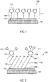
- the reduction catalyst of the first embodiment will be explained below with reference to Figure 1 , which schematically shows a structure of the reduction catalyst 100.
- the reduction catalyst comprises a current collector 101 and organic modifying groups 112.
- the current collector 101 supports an electric conductor 102 provided thereon.
- the organic modifying groups 112 are combined with the electric conductor 102 to form a self-assembled monolayer (SAM) 111.
- SAM self-assembled monolayer
- organic molecules giving the organic modifying groups are referred to as "organic modifying molecules”.
- the current collector 101 is made of material having electroconductivity.
- the current collector 101 may be a stainless-steel substrate.
- the electric conductor 102 which is placed on the surface of the current collector 101, preferably contains at least one metal selected from the group consisting of: Au, Ag, Cu, Zn, Pt, Fe, Ti, Ni, Sn, In and Bi.
- the conductor 102 can contain ingredients other than metals, but preferably consists of metals only.
- the electric conductor can be made of electroconductive metal oxides, such as, oxides selected from the group consisting of Ag 2 O, CuO, Ta 2 O 5 TiO 2 , ZrO 2 , Al 2 O 3 , SiO 2 ZnO, ITO, and FTO.
- the electric conductor 102 and the current collector 101 may be made of the same material. In that case, the metal of the conductor 102 may serve also as the collector 101.
- the metal contained in the electric conductor 102 functions as a catalyst activating the reduction reaction. Accordingly, the metal in the conductor 102 is preferably in the form of such fine particles as to enhance the catalytic activity.
- the particles preferably have a mean size of 1 to 300 nm inclusive because the mean size of 300 nm or less can increase efficiency of the catalytic activity. It is, however, difficult to produce the fine particles having a mean size of less than 1 nm.
- the mean particle size is more preferably 150 nm or less because the catalytic activity efficiency is more increased.
- the metal particles either may be primary particles having a mean size of 50 nm or less, or may be secondary particles derived from aggregation of those primary particles.
- the organic modifying group 112 comprises a heteroatom-containing group 109 at one terminal and a nitrogen-containing group at the other terminal.
- the heteroatom-containing group and the nitrogen-containing group are -S- and imidazole groups, respectively.
- the organic modifying group is not limited to that in Figure 1 , and it is possible to adopt groups having a structure represented by the following formula (A) or (B): in which
- the nitrogen atom contained in the organic modifying group is presumed to capture the objective compound aimed to reduce, and accordingly the reaction efficiency also depends on the structures of substituent groups linking to the nitrogen atom
- the number of carbon atoms contained in R a of the formula (A) is preferably large to a certain degree in view of increasing acidity of the organic modifying group, but on the other hand if having many carbon atoms, R a may be bulky to cause steric hindrance. Accordingly, R a is limited to H or an alkyl group of C 1 to C 4 . Further, Z necessarily contains two or more nitrogen atoms for the purpose of ensuring adequate interaction with the objective atom, and the aromatic ring thereof is preferably a 5- or 6-membered one.
- the organic modifying group represented by the formula (B) include groups represented by the following formula (B-1) or (B-2): in which nb and Y are the same as those described above.
- the heteroatom-containing group 109 in Figure 1 corresponds to Y in the formula (A) or (B).
- the group 109 has affinity with the electric conductor 102, and hence chemically combines therewith.
- the organic modifying group 112 is thus fixed on the conductor 102.
- the heteroatom-containing group 109 is preferably capable of forming a covalent bond with the conductor 102.
- Preferred examples of the group 109 include groups derived from thiol, disulfide and thiocyanate groups.
- the organic modifying group 112 is preferably derived from an organic modifying molecule selected from the group consisting of: aminoethanethiol, aminopropanethiol, aminobutanethiol, methylaminoethanethiol, isopropylethylaminoethanethiol, dimethylaminoethanethiol, diethylaminoethanethiol, dibutylaminoethanethiol, mercaptoethylimidazole, mercaptopropylimidazole, mercaptobutylimidazole, captohexylimidazole, mercaptotriazole, mercaptoethyltriazole, mercaptopropyltriazole, mercaptobutyltriazole, and mercaptohexyltriazole.
- an organic modifying molecule selected from the group consisting of: aminoethanethiol, aminopropanethiol, amino
- the reduction catalyst 100 can be produced in the following manner.
- the electric conductor 102 is formed on the surface of the current collector 101 by a known vacuum film-forming technique, such as, sputtering, vacuum deposition or ALD (atomic layer deposition).
- a known vacuum film-forming technique such as, sputtering, vacuum deposition or ALD (atomic layer deposition).
- the heteroatom-containing group 109 is then combined with the electric conductor 102, so that the organic modifying group 112 is fixed on the conductor 102.
- This procedure can be carried out in known manners.
- the collector 101 provided with the conductor 102 is brought into contact with a solution in which the organic modifying molecules are dissolved.
- the organic modifying molecules may be vaporized in high vacuum and deposited to form a film thereof on the surface of the collector 101, or otherwise the modifying molecules may be sprayed onto the surface of the collector 101.
- the modifying groups 112 are chemically adsorbed on the conductor 102 and then spontaneously form aggregates by the action of Van der Waals forces and hydrophobic interactions among the adsorbed molecules.
- the adsorbed molecules thus densely aggregate and consequently form an oriented monolayer.
- Any solvent capable of dissolving the organic modifying molecules can be adopted to prepare the solution.
- it can be selected from alcohols such as ethanol, aromatic organic solvents such as toluene and hexane, or aliphatic ones.
- alcohols such as ethanol
- aromatic organic solvents such as toluene and hexane
- aliphatic ones Among them, ethanol is preferred because the modifying groups 112 are well dissolved therein and it is easy to handle.
- the procedure for fixing the modifying groups 112 on the conductor 102 is, for example, carried out in the manner described below in detail.
- the organic modifying molecules are dissolved to prepare a solution.
- the collector 101 provided with the conductor 102 is then immersed for several minutes to several hours.
- the modifying groups 112 are fixed on the surface of the conductor 102.
- the conditions, such as, concentration of the modifying molecules, immersion time and temperature, can be adequately changed according to the structure of the modifying groups 112 and the like. Those conditions influence formation of the monolayer of the modifying groups 112.
- the concentration of the modifying groups 112 is preferably 0.1 to 100 mM inclusive, more preferably 1 to 10 mM inclusive.
- the immersion time is preferably long enough to form a dense and oriented monolayer, and is preferably 1 minute to 100 hours inclusive, more preferably 12 to 72 hours inclusive.
- the temperature of the solution during the immersion step influences formation of the dense and oriented monolayer.
- the temperature is preferably room temperature (25°C) to 60°C inclusive.
- the surface analysis can be carried out with a Fouier transform infrared (FT-IR) reflection spectrophotometer. This analysis can sensitively measure IR spectra of the thin layer and the molecular species adsorbed on the surface of the collector 101. Accordingly, the analysis can reveal the structure of the organic molecule and particularly can provide knowledge of the functional groups therein.
- the surface analysis also can be carried out by X-ray photoelectron spectroscopy (XPS). This analysis can determine the elemental species of the molecules.
- the reduction catalyst 100 contains a nitrogen-containing group, which has such high affinity with CO 2 as to contribute toward generation and stabilization of a CO 2 radical anion. Further, the nitrogen-containing group reacts with a CO 2 molecule to form a carbonate. The nitrogen-containing groups thus attract CO 2 molecules necessary for the reduction reaction, and then form salts with resultant carboxylic acids (such as, formic acid, acetic acid, oxalic acid) produced by the CO 2 reduction. Because of that, the catalyst has an effect of promoting a multielectron reduction reaction in which the reduction proceeds continuously. In this way, the reduction catalyst 100 makes it possible to improve the reduction efficiency and hence can cause the CO 2 reduction reaction with low energy. As a result, the reduction catalyst can improve the energy conversion efficiency.
- the monolayer densely combined with the conductor 102 has an effect of preventing H 2 O and H + from approaching the conductor, and hence provides reaction selectivity of reduction on the conductor 102. This means that the monolayer can inhibit generation of H 2 caused by the side reactions and accordingly can improve the faradaic efficiency.
- the present embodiment can provide a reduction catalyst of high reaction efficiency.
- the reduction catalyst according to the embodiment can be applied to reduction of a material selected from the group consisting of carbon dioxide, oxalic acid and glyoxal.
- Reduction products depend on interactions among the organic modifying molecule, the conductor 102 and the material aimed to reduce.
- formable reduction products are carbon monoxide (CO), formic acid (HCOOH), formic aldehyde (HCHO), methanol (CH 3 OH), acetic acid (CH 3 COOH), acetaldehyde (CH 3 CHO), ethanol (CH 3 CH 2 OH), oxalic acid ((COOH) 2 ), glyoxal and ethylene glycol (HOCH 2 CH 2 OH).
- the reduction catalyst 100 of the present embodiment can produce ethylene glycol in high selectivity. It becomes, therefore, possible to provide a reduction catalyst-application process in which the reduction catalyst 100 is used to reduce a material selected from the group consisting of carbon dioxide, oxalic acid and glyoxal and thereby to produce products including ethylene glycol.
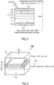
- FIG 2 schematically shows the structure of a reduction catalyst 150 according to the present embodiment.
- the reduction catalyst 150 comprises a current collector 101 provided with an electric conductor 102, a spacer organic molecule layer 105 formed on the surface of the conductor 102, metal fine particles 107 linked to the surface of the spacer organic molecule layer 105, and organic modifying groups 112 combined with the metal fine particles 107.
- the metal fine particle 107 functions as the electric conductor.
- this embodiment comprises two kind of the electric conductor.
- the collector 101 and the conductor 102 may be the same as those in the first embodiment.
- the spacer organic molecule layer 105 is a self-assembled monolayer formed through a process in which spacer groups 106 derived from spacer organic molecules are adsorbed and then self-assembled on the surface of the conductor 102.
- the spacer group 106 comprises, for example, an alkylene skeleton 106A, a first reactive functional group 106B positioned at one terminal, and a second reactive functional group 106C positioned at the other terminal.
- the spacer group 106 contains preferably 2 to 12, more preferably 2 to 6 carbon atoms in total.
- the first reactive functional group 106B has affinity with the electric conductor 102, and hence chemically combines therewith.
- the organic spacer group 106 is thus fixed on the conductor 102.
- the first reactive functional group 106B is preferably capable of forming a covalent bond with the conductor 102.
- Preferred examples of the group 106 include groups derived from thiol, disulfide and thiocyanate groups.
- the second reactive functional group 106C has affinity with the metal fine particle 107, and hence chemically combines therewith.
- the particle 107 is thus fixed on the spacer organic molecule layer 105.
- the second reactive functional group 106C is preferably capable of forming an electrostatic bond with the particle 107 charged electrically, and preferred examples thereof include amino group and carboxyl group.
- the second reactive functional group 106C is preferably capable of forming a covalent bond with the particle 107, and preferred examples thereof include groups derived from thiol, disulfide and thiocyanate groups.
- spacer organic molecules capable of forming the spacer layer 105 include the same molecules as those giving the organic modifying group 112 described above in the first embodiment.
- the examples further include such molecules as: 10-carboxy-1-decanethiol, 7-carboxy-1-heptanethiol, 5-carboxy-1-pentanethiol, 3-carboxy-1-pentanethiol, mercaptoacetic acid, 10-carboxydecyl disulfide, 7-carboxyheptyl-disulfide, 5-carboxypentyl-disulfide, 4,4'-dithiodibutanoic acid, 11-amino-1-undecanethiol, 8-amino-1-octanethiol, 1,2-ethanedithiol, 1,3-propanedithiol, 1,4-butanedithiol, 1,5-pentanedithiol, 1,6-hexanedithi
- the metal fine particles 107 function as a catalyst activating the reduction reaction. They are made of at least one element selected from the group consisting of Au, Ag, Cu, Pt, Zn, Fe, Ti, Sn, Bi and Ni.
- the fine particles 107 are preferably those of Au or Ag because they have high catalytic activity.
- the metal particles 107 preferably have a mean size of 1 to 300 nm inclusive because the mean size of 300 nm or less can increase the efficiency of the catalytic activity. It is, however, difficult to produce the particles 107 having a mean size of less than 1 nm.
- the mean particle size is more preferably 150 nm or less because the efficiency of catalytic activity is more increased.
- the metal particles 107 either may be primary particles having a mean size of 50 nm or less, or may be secondary particles derived from aggregation of those primary particles.
- the mean size of the particles 107 can be determined according to particle size distribution measurement by dynamic light scattering. Specifically, the fine particles 107 are dispersed in a solution and then laser beams are applied to the dispersion to detect fluctuating scattered light. The fluctuation of scattered light suggests the diffusion coefficient, and hence the particle size can be calculated from the result according to the Stokes-Einstein equation. How frequently the particles of each size are thus detected is integrated to obtain a frequency distribution, in which the most frequent size or the size giving the maximum frequency is the mode size of the distribution. The mode size is regarded as the mean particle size.
- the metal fine particle 107 may have an electrically charged organic molecule 108 on a part of the surface. That particle 107 consequently has an electrically charged surface.
- the charge on the particle 107 can be so controlled that the particle 107 can be fixed on the spacer organic molecule layer 105 through electrostatic attraction (electrostatic attraction bond) to the charge of the second reactive functional group 106C.
- the organic molecule 108 may be charged either positively or negatively.
- the spacer organic molecule 106 is so selected as to have an amino group as the second reactive functional group 106C for fixing the particle 107.
- the spacer molecule 106 is so selected as to have a carboxyl group as the second reactive functional group 106C for fixing the particle 107.
- fine particles 107 If the fine particles 107 are thus electrically charged, they electrostatically repel each other and hence can be prevented from gathering to form aggregates of nanosize particles.
- the organic modifying group 112 is linked to the particle 107, and has an effect of promoting the reduction reaction.
- the modifying group 112 can be the same as that in the first embodiment.
- the heteroatom-containing group 109 in the modifying group 112 has affinity with the particle 107, and hence chemically combines therewith.
- the modifying group 112 is thus fixed on the metal fine particle 107.
- the metal fine particles are loaded on a spacer layer that is made of organic material and formed on another electric conductor on a current collector.
- the reduction catalyst 150 can be produced in the following manner.
- the electric conductor 102 is formed on the surface of the current collector 101 by a known vacuum film-forming technique, such as, sputtering, vacuum deposition or ALD (atomic layer deposition).
- the spacer groups 106 are then fixed on the conductor 102 to form the spacer organic molecule layer 105. This procedure can be carried out in the same manner as that for fixing the modifying groups 112 on the conductor 102 in a production process of the reduction catalyst 100 according to the first embodiment.
- the metal fine particles 107 are prepared. If necessary, the organic molecule 108 is fixed on the particle. This procedure can be carried out in the following first or second manner.
- a reducing agent such as citric acid is employed to conduct reduction when metal fine particles are obtained from a liquid phase.
- the agent such as citric acid is attached on the surface of the particle thus obtained, and thereby the surface is negatively charged. Successively, the negatively charged surface is electrostatically combined with a molecule having an amino group.
- an uncharged surface of the particle is combined with an amine molecule having a covalent reactive group such as thiol. This process makes it possible to fix a charged organic molecule whether the particle surface is charged positively, negatively or not.
- the metal fine particles 107 loaded with the charged organic molecules 108 are fixed on the surface of the spacer organic molecule layer 105.
- the particles 107 are dispersed in a disperse medium to prepare a dispersion, in which the collector 101 provided with the spacer layer 105 formed thereon is then immersed.
- the second reactive group 106C in the spacer layer 105 is electrostatically combined with the organic molecules 108 on the particle 107 and thereby the particle 107 is fixed on the spacer layer 105.
- the disperse medium in which the particles 107 are dispersed is not particularly restricted as long as it can stably disperse the particles.
- examples thereof include water, ethanol and toluene, and preferred are water and ethanol because they are easy to handle.
- the dispersion conditions such as, concentration, immersion time and temperature, are adequately determined because they depend on the synthesis method and stability of the metal fine particles 107.
- the concentration of the particles in the dispersion is preferably 0.01 to 10 mM inclusive, more preferably 0.1 to 1 mM inclusive.
- the immersion time is preferably 1 to 50 hours inclusive, more preferably 5 to 24 hours inclusive so that the particles 107 can be fixed in a sufficient amount.
- the dispersion temperature during the immersion step is preferably room temperature (25°C) to 35°C inclusive. At a high temperature, there is a fear that the dispersion stability of the particles 107 is so lowered that they may aggregate.
- the metal composition can be analyzed according to, for example, energy dispersive X-ray spectrometry (EDX), electron probe microanalysis (EPMA) or X-ray photoelectron spectroscopy (XPS).
- SEM scanning electron microscope
- TEM transmission electron microscope
- AFM atomic force microscope
- STEM scanning transmission microscope
- EDX energy dispersive X-ray spectrometry
- EPMA electron probe microanalysis
- XPS X-ray photoelectron spectroscopy
- the organic modifying group 112 is combined with the particle 107 fixed on the spacer layer 105.
- This procedure can be carried out in the same manner as that for fixing the modifying groups 112 on the conductor 102 in a production process of the reduction catalyst 100 according to the first embodiment.
- the procedure for fixing the modifying group 112 on the particle 107 is, for example, carried out in the manner described below in detail.
- the organic modifying molecules are dissolved to prepare a solution containing the modifying groups 112 dissolved therein.
- the collector 101 provided with the metal fine particles 102 is then immersed for several minutes to several hours.
- the modifying groups 112 are fixed on the surface of the particles 107.
- the conditions, such as, concentration of the modifying groups, immersion time and temperature, can be adequately changed according to the structure of the modifying groups 112 and the like.
- the concentration of the modifying groups 112 is preferably 0.1 to 100 mM inclusive, more preferably 1 to 10 mM inclusive.
- the immersion time is preferably long enough to form a dense and oriented monolayer, and is preferably 1 minute to 100 hours inclusive, more preferably 12 to 72 hours inclusive.
- the prepared solution temperature during the immersion step influences formation of the dense and oriented monolayer.
- the temperature is preferably room temperature (25°C) to 60°C inclusive.
- the reduction catalyst 150 can be produced.
- the reduction catalyst 150 As an example of the reaction with the reduction catalyst 150, reduction of CO 2 is then explained below. As described in the first embodiment, the elementary reaction of normal CO 2 reduction has a problem of low faradaic efficiency. However, the reduction catalyst 150 according to the present embodiment can realize high reduction efficiency.
- the reduction reaction proceeds at the metal fine particle 107, where the modifying groups 112 reacts with CO 2 to form a reaction intermediate.
- the catalyst thus contributes toward generation and stabilization of a CO 2 radical anion, and hence can cause the CO 2 reduction reaction with low energy.
- the reduction catalyst can improve the energy conversion efficiency.
- the monolayer has an effect of preventing H 2 O and H + from approaching the particles 107, and hence provides reaction selectivity of reduction on the particles 107. This means that the monolayer can inhibit generation of H 2 caused by the side reactions, and accordingly can improve the faradaic efficiency.
- the amino group in the modifying group 112 reacts with a CO 2 molecule to form a carbonate.
- the amino groups thus attract CO 2 molecules necessary for the reduction reaction, and provide them to the metal fine particles 107.
- the amino groups form salts with resultant carboxylic acids (such as, formic acid, acetic acid, oxalic acid) produced by the CO 2 reduction. Because of that, the catalyst has an effect of promoting a multielectron reduction reaction in which the reduction proceeds continuously. As a result, the reduction catalyst can improve the energy conversion efficiency.
- the reduction catalyst 150 can have a larger reaction area (surface area) than a tabular metal layer. Accordingly, the reduction efficiency can be further improved.
- the present embodiment can provide a reduction catalyst of high reaction efficiency.
- the reduction catalyst 150 can be applied to reduction of a material selected from the group consisting of carbon dioxide, oxalic acid and glyoxal.
- Reduction products depend on interactions among the organic modifying molecules, the conductor 102 and the material aimed to reduce.
- formable reduction products are carbon monoxide (CO), formic acid (HCOOH), formic aldehyde (HCHO), methanol (CH 3 OH), acetic acid (CH 3 COOH), acetaldehyde (CH 3 CHO), ethanol (CH 3 CH 2 OH), oxalic acid ((COOH) 2 ), glyoxal and ethylene glycol (HOCH 2 CH 2 OH).
- the reduction catalyst 150 of the present embodiment can produce ethylene glycol in high selectivity. It becomes, therefore, possible to provide a reduction catalyst-application process in which the reduction catalyst 150 is used to reduce a material selected from the group consisting of carbon dioxide, oxalic acid and glyoxal and thereby to produce products including ethylene glycol.
- the following describes a chemical reactor employing the reduction catalyst according to the first embodiment. Although the explanation is omitted, the reduction catalyst according to the second embodiment also can be used in place of that of the first embodiment.
- the chemical reactor comprises a photochemical reaction cell, which is explained below with referring to Figures 3 to 5 .
- the photochemical reaction cell comprises an oxidation catalyst layer, a reduction catalyst layer containing the reduction catalyst, and a power supply unit connected to the oxidation and reduction catalyst layers.
- the power supply unit preferably comprises a semiconductor layer in which charge separation is caused by light energy, and is preferably a solar cell, for example.
- the semiconductor layer is preferably placed between the oxidation and reduction catalyst layers.
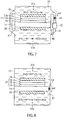
- Figure 3 is a sectional view schematically showing the structure of a photochemical reaction cell 30.
- the reaction cell 30 is a laminate in which a reduction catalyst layer 20, a substrate 11, a reflection layer 12, a reduction electrode layer 13, a multi-junction solar cell 17, an oxidation electrode layer 18 and an oxidation catalyst layer 19 are stacked in this order.
- the reduction catalyst layer 20 is placed on the back side and the oxidation catalyst layer 19 is placed on the top side exposed to light.
- the substrate 11 is provided for the purposes of supporting the photochemical reaction cell and of enhancing mechanical strength thereof. It is, for example, a plate made of a metal selected from the group consisting of Au, Ag, Cu, Pt, Zn, Fe, Ti, Sn, In, Bi and Ni or of an alloy containing at least one of them.
- the alloy plate is, for example, a plate of SUS.
- the substrate 11 also can be made of electroconductive resins, semiconductors such as Si and Ge, or ion-exchange membranes.
- the reflection layer 12 is formed on the surface of the substrate 11, and is made of a material capable of reflecting light.
- it may be a distributed Bragg reflector comprising a metal layer or a semiconductor multilayer.
- the reflection layer 12 is placed between the substrate 11 and the multi-junction solar cell 17, and hence can reflect light not absorbed by the solar cell 17 so that the light can reenter the solar cell 17.
- the reflection layer 12 thus can enhance light absorption of the solar cell 17.
- the reduction electrode layer 13 is placed on the reflection layer 12, and sandwiched between the reflection layer 12 and an n-type semiconductor layer (n-type amorphous silicon layer 14a, described later) in the solar cell 17. Accordingly, the reduction electrode layer 13 is preferably made of a material capable of having ohmic contact with the n-type semiconductor layer.
- the electrode layer 13 is made of a metal such as Au, Ag, Al or Cu or made of an alloy containing at least one of them.
- the reduction electrode layer 13 may be made of a transparent electroconductive oxide, such as, ITO (indium tin oxide), zinc oxide (ZnO), FTO (fluorine-doped tin oxide), AZO (aluminum-doped zinc oxide) or ATO (antimony-doped tin oxide). Further, the electrode layer 13 also may have a structure, for example, in which a metal and a transparent electroconductive oxide are laminated, in which a metal and another electroconductive material are combined, or in which a transparent electroconductive oxide and another electroconductive material are combined.
- ITO indium tin oxide
- ZnO zinc oxide
- FTO fluorine-doped tin oxide
- AZO aluminum-doped zinc oxide
- ATO antimony-doped tin oxide
- the multi-junction solar cell 17 is placed on the reduction electrode layer 13, and is a laminate in which a first solar cell 14, a second solar cell 15 and a third solar cell 16 are stacked in this order from the electrode layer 13 side. All of those cells employ pin-junction semiconductors.
- the first, second and third solar cells 14, 15 and 16 are different from each other in the light absorption wavelength region. Since comprising those cells laminated tabularly, the multi-junction solar cell 17 can absorb sunlight in a wide wavelength range. Thus, it becomes possible to utilize solar energy efficiently. Further, since the solar cells are connected in series, it is possible to obtain a high open circuit voltage.
- the first solar cell 14 comprises an n-type amorphous silicon (a-Si) layer 14a, an intrinsic amorphous silicon germanium (a-SiGe) layer 14b, and a p-type fine-crystalline silicon ( ⁇ c-Si) layer 14c stacked in the order from the electrode layer 13 side.
- the a-SiGe layer 14b absorbs light in a short wavelength region around 400 nm. Accordingly, in the first solar cell 14, charge separation is caused by light energy in the short wavelength region.
- the second solar cell 15 comprises an n-type a-Si layer 15a, an intrinsic a-SiGe layer 15b, and a p-type ⁇ c-Si layer 15c stacked in the order from the electrode layer 13 side.
- the a-SiGe layer 15b absorbs light in an intermediate wavelength region around 600 nm. Accordingly, in the second solar cell 15, charge separation is caused by light energy in the intermediate wavelength region.
- the third solar cell 16 comprises an n-type a-Si layer 16a, an intrinsic a-SiGe layer 16b, and a p-type ⁇ c-Si layer 16c stacked in the order from the electrode layer 13 side.
- the a-SiGe layer 16b absorbs light in a long wavelength region around 700 nm. Accordingly, in the third solar cell 16, charge separation is caused by light energy in the long wavelength region.
- the multi-junction solar cell 17 charge separation is thus caused by light in each wavelength region and consequently positive holes and electrons are separated and moved to the positive electrode side (top side) and to the negative electrode side (back side), respectively. In this way, the multi-junction solar cell 17 generates electromotive force.
- the multi-junction solar cell 17 comprising a laminate of three solar cells, but the present embodiment is not limited to the above.
- the embodiment may employ a single solar cell.
- the solar cells described above comprise pin-junction semiconductors, the embodiment may employ a solar cell of pn-junction semiconductors.
- the solar cell may comprise a semiconductor layer of, for example, GaAs, GaInP, AlGaInP, CdTe or CuInGaSe, and the semiconductors may be in any form, such as, single crystal, multicrystal or amorphous.
- the oxidation electrode layer 18 is placed on the multi-junction solar cell 17, and sandwiched between the p-type semiconductor layer in the solar cell 17 and the oxidation catalyst layer 19. Accordingly, the oxidation electrode layer 18 is preferably made of a transparent material capable of having ohmic contact with the p-type semiconductor layer.
- the electrode layer 18 is made of a transparent electroconductive oxide, such as, ITO (indium tin oxide), zinc oxide (ZnO), FTO (fluorine- doped tin oxide), AZO (aluminum-doped zinc oxide) or ATO (antimony-doped tin oxide).
- the electrode layer 18 may have a structure, for example, in which a metal and a transparent electroconductive oxide are laminated, in which a metal and another electroconductive material are combined, or in which a transparent electroconductive oxide and another electroconductive material are combined.
- the oxidation catalyst layer 19 is placed on the positive electrode side of the multi-junction solar cell 17, and is formed on the oxidation electrode layer 18.
- the oxidation catalyst layer 19 oxidizes H 2 O to generate O 2 and H + .
- it oxidizes OH - to generate O 2 and H 2 O when the electrolyte solution has a hydrogen ion concentration of more than 7 (pH > 7).
- the catalyst layer 19 is made of a material lowering activation energy of the oxidation reaction, that is, a material lowering overvoltage of the reaction in which H 2 O or OH - is oxidized to extract electrons.
- Examples of the material include: binary metal oxides, such as, manganese oxide (Mn-O), iridium oxide (Ir-O), nickel oxide (Ni-O), cobalt oxide (Co-O), iron oxide (Fe-O), Tin oxide (Sn-O), indium oxide (In-O) and ruthenium oxide (Ru-O); ternary metal oxides, such as, Ni-Co-O, La-Co-O, Ni-La-O and Sr-Fe-O; quaternary metal oxides, such as, Pb-Ru-Ir-O and La-Sr-Co-O; and metal complexes, such as, Ru complexes and Fe complexes.
- binary metal oxides such as, manganese oxide (Mn-O), iridium oxide (Ir-O), nickel oxide (Ni-O), cobalt oxide (Co-O), iron oxide (Fe-O), Tin oxide (Sn-O), indium oxide (In-O) and ruthenium oxide (Ru-O);
- the oxidation catalyst layer 19 is in the form not restricted to a thin film, and may be in the form of, for example, a grid, particles or a wire.
- the catalyst layer 19 and the electrode layer 18 are transparent to the incident light. Specifically, they are so transparent that the light can pass in an amount of 10% or more, preferably 30% or more.
- the reduction catalyst layer 20 is placed on the negative electrode side of the multi-junction solar cell 17, and is formed on the back surface of the substrate 11.
- the reduction catalyst layer 20 reduces a material aimed to reduce, such as CO 2 , and thereby generates carbon compounds (e.g., carbon monoxide, formic acid, formic aldehyde, methane, methanol, acetic acid, acetaldehyde, ethanol, ethylene glycol).
- the catalyst layer 20 is made of a material lowering activation energy for reducing the material aimed to reduce.
- the reduction catalyst 100 of the first embodiment is employed.
- the reduction catalyst layer 20 comprises the current collector 101 and the organic modifying groups 112 having quaternary nitrogen cations.
- the collector 101 may serve as the substrate 11.
- an electroconductive protective layer on the surface of the multi-junction solar cell 17 or between the electrode layer and the catalyst layer on the light-incident side (i.e., between the oxidation electrode layer 18 and the oxidation catalyst layer 19 in the photochemical reaction cell 30).
- the protective layer protects the solar cell 17 from corrosion in the oxidation-reduction reaction, and consequently can extend the working lifetime of the solar cell 17. If necessary, the protective layer may be transparent. Examples of the protective layer include: dielectric thin films of TiO 2 , ZrO 2 , Al 2 O 3 , SiO 2 and HfO 2 .
- the protective layer has a thickness of preferably 10 nm or less, more preferably 5 nm or less so as to ensure electric conductivity based on tunneling effect.
- Figures 4 and 5 are schematic sectional views illustrating the working principle of the photochemical reaction cell 30. In those figures, the reflection layer 12, the reduction electrode layer 13 and the oxidation electrode layer 18 are omitted.
- incident light (L) passes through the oxidation catalyst layer 19 and reaches to the multi-junction solar cell 17.
- the solar cell 17 absorbs the light to generate photoexcited electrons and their counterpart positive holes, which are then separated.
- the photoexcited electrons move to the n-type semiconductor layer side (reduction catalyst layer 20 side) while the holes counterpart to the photoexcited electrons move to the p-type semiconductor layer side (oxidation catalyst layer 19 side). Because of charge separation thus caused, the multi-junction solar cell 17 generates electromotive force.
- the photoexcited electrons generated in the solar cell 17 are used in the reduction reaction on the reduction catalyst layer 20 serving as the negative electrode.
- the positive holes are used in the oxidation reaction on the oxidation catalyst layer 19 serving as the positive electrode.
- Figure 4 shows an example when the electrolyte solution is an acidic solution, which has a hydrogen ion concentration of less than 7.
- the following reaction (1) proceeds near the oxidation catalyst layer 19, so that H 2 O is oxidized to generate H + , O 2 and electrons.
- the generated H + moves to the reduction catalyst layer 20 side by way of the ion migration path described later.
- the following reaction (2) proceeds near the reduction catalyst layer 20, so that CO 2 is reduced by the transferred H + and electrons to generate carbon monoxide (CO) and H 2 O.
- Figure 5 shows an example when the electrolyte solution is a basic solution, which has a hydrogen ion concentration of more than 7.
- the following reaction (3) proceeds near the oxidation catalyst layer 19, so that OH - is oxidized to generate O 2 , H 2 O and electrons.
- the following reaction (4) proceeds near the reduction catalyst layer 20, so that both CO 2 and H 2 O receive the electrons and are thereby reduced to generate carbon monoxide (CO) and OH - .
- the OH - generated on the reduction catalyst layer 20 side moves to the oxidation catalyst layer 19 side by way of the ion migration path described later.
- the multi-junction solar cell 17 necessarily has an open circuit voltage not less than the difference between the standard potential of oxidation on the oxidation catalyst layer 19 and that of reduction on the reduction catalyst layer 20.
- the standard potential of oxidation in the formula (1) is +1.23 V while that of reduction in the formula (2) is -0.1 V. Accordingly, the multi-junction solar cell 17 must have an open circuit voltage of 1.33 V or more.
- the open circuit voltage is more preferably required to be not less than the potential difference including the overvoltage. Specifically, if there is an overvoltage of 0.2 V in each of the oxidation and reduction in the formulas (1) and (2), respectively, the open circuit voltage is preferably 1.73 V or more.
- the reduction reaction is not limited to that.
- the chemical reactor according to the present embodiment is provided with an ion migration path through which H + or OH - can be transferred. The reactor can be thus improved in the migration of H + or OH - . In this way, the present embodiment can realize high photoreaction efficiency.
- the chemical reactor comprising the above photochemical reaction cell is then explained below with referring to Figures 6 to 9 .
- the oxidation-reduction reaction in the following explanation is thought to proceed under the condition where the electrolyte solution has a hydrogen ion concentration of less than 7, that is, where the solution is acidic (i.e., the reaction corresponds to the formulas (1) and (2)). If the electrolyte solution has a hydrogen ion concentration of more than 7, that is, if the solution is basic, the oxidation-reduction reaction proceeds according to the formulas (3) and (4).
- FIG. 6 is a perspective view schematically illustrating a structure of the photochemical reactor 200 according to the present embodiment
- Figure 7 is a schematic sectional view showing a structure of the reactor 200.
- the reactor 200 comprises: a photochemical reaction cell 30, an electrolytic bath 31 containing the photochemical reaction cell, and an electrolytic bath flow channel 41 serving as the ion migration path linked to the bath 31.
- the ion migration path is omitted.
- the photochemical reaction cell 30 comprises a laminate of the oxidation catalyst layer 19, the reduction catalyst layer 20, the multi-junction solar cell 17 sandwiched between them, and the substrate 11.
- the electrolytic bath 31 comprises an oxidation electrolytic bath 31a provided with the oxidation catalyst layer 19 and a reduction electrolytic bath 31b provided with the reduction catalyst layer 20.
- H 2 O is oxidized by the catalyst layer 19 to generate O 2 and H + .
- CO 2 is reduced by the catalyst layer 20 to generate CO and H 2 O.
- Those electrolytic bathes are separated with the substrate 11 of the photochemical reaction cell 30.
- the substrate 11 is larger than the solar cell 17 and the catalyst layers 19 and 20 and hence the side ends of the substrate protrudes from both sides.
- this example by no means restricts the substrate 11, and all of the substrate 11, the solar cell 17 and the catalyst layers 19 and 20 may be the same size tabular plates.
- the flow channel 41 which enables ions to migrate, connects the bathes 31a and 31b.
- the flow channel 41 thus enables H + generated on the oxidation catalyst layer 19 side to migrate to the reduction catalyst layer 20 side, and hence CO 2 can be decomposed with the transferred H + on the reduction catalyst layer 20 side. In this way, the present embodiment can realize high photoreaction efficiency.
- the electrolytic bath flow channel 41 is then explained below in detail.
- the flow channel 41 is, for example, provided on the side of the electrolytic bath 31.
- One end of the channel 41 is connected to the oxidation electrolytic bath 31a and the other is connected to the reduction bath 31b.
- the flow channel 41 thus connects the oxidation bath 31a with the reduction bath 31b, and thereby it enables ions to move between the catalyst layers 19 and 20.
- ion-exchange membranes 43 are provided in a part of the flow channel 41.
- the ion-exchange membranes 43 selectively allow particular ions to pass through, and thereby the electrolyte solution is separated and at the same time only the particular ions are transferred between the bathes 31a and 31b.
- the ion-exchange membranes 43 are proton exchange ones, and can transfer H + generated in the oxidation bath 31a to the reduction bath 31b.
- Examples of the proton exchange membranes include: cation exchange membranes, such as, Nafion and Flemion; and anion exchange membranes, such as, Neosepta and Selemion.
- the ion-exchange membranes 43 may be replaced with, for example, a salt bridge made of a material, such as agar, capable of transferring ions and of separating the electrolyte solution.
- a salt bridge made of a material, such as agar, capable of transferring ions and of separating the electrolyte solution.
- the proton exchange membranes of solid polymer, such as Nafion generally can improve the ion mobility.
- the flow channel 41 may be equipped with a circulation mechanism 42, such as, a pump.
- the circulation mechanism 42 promotes circulation of the electrolyte solution so as to enhance circulation of ions (H + ) between the bathes 31a and 31b.
- the circulation mechanism 42 is installed in at least one channel.
- ions are transferred with the mechanism 42 through one of the channels 41 from the oxidation bath 31a to the reduction bath 31b and through the other channel 14 from the reduction bath 31b to the oxidation bath 31a.
- the flow channel 41 may be equipped with two or more circulation mechanisms 42. Further, for the purposes of lowering diffusion of ions and thereby of circulating them efficiently, there may be a plural number (three or more) of flow channels 41.
- the circulation mechanism 42 can prevent bubbles of generated gases from remaining on the surfaces of the electrodes and bathes and hence from scattering the sunlight to lower the efficiency and to change the light quantity distribution.
- the surface of the multi-junction solar cell 17 may be heated to cause thermal difference in the electrolyte solution.
- the thermal difference can be utilized to cause convection by which ions are efficiently circulated. In this case, circulation of ions can be promoted more than diffusion thereof.
- the flow channel 41 or the electrolytic bath 31 may be equipped with a thermostat mechanism 44 for controlling the electrolyte solution temperature.
- the thermostat 44 can adjust the temperature so as to control performances of the solar cell and the catalysts.
- the reaction system can be made thermally homogeneous to improve and stabilize the performances of the solar cell and the catalysts. Further, the temperature can be prevented from rising to stabilize the system. Furthermore, the temperature can be so controlled as to change selectivity of the solar cell and the catalysts and thereby to control the reaction products.
- the oxidation electrolytic bath 31a is filled with an electrolyte solution containing desired electrolytes.
- the oxidation catalyst layer 19 is immersed in the electrolyte solution.
- the electrolyte solution preferably promotes the oxidation reaction of H 2 O and is, for example, a liquid containing H 2 O.
- the reduction electrolytic bath 31b is filled with an electrolyte solution containing desired electrolytes.
- the reduction catalyst layer 20 is immersed in the electrolyte solution. It is preferred for the electrolyte solution to lower the reduction potential of CO 2 to have high ion conductivity and to contain a CO 2 absorber capable of absorbing CO 2 .
- the electrolyte solution is, for example, a liquid containing CO 2 .
- Examples of the electrolyte solution loaded in the reduction bath 31b include: an ionic liquid which consists of a cation such as imidazolium or pyridinium ion and an anion such as BF 4 - or PF 6 - and which can be in a liquid state in a wide temperature range; an amine solution such as ethanolamine, imidazole or pyridine solution; and an aqueous solution thereof.
- the amine may be either primary, secondary or tertiary. Examples of the primary amine include: methylamine, ethylamine, propylamine, butylamine, pentylamine, and hexylamine.
- the hydrocarbon group substituted with amine may be alcohol or may be substituted with halogens. Examples thereof include methanolamine, ethanolamine, and chloromethylamine.
- the hydrocarbon group substituted with amine may have an unsaturated bond.
- Examples of the secondary amine include: dimethylamine, diethylamine, dipropylamine, dibutylamine, dipentylamine, dihexylamine, dimethanolamine, diethanolamine, dipropanolamine, methylethylamine, and methylpropylamine.
- tertiary amine examples include: trimethylamine, triethylamine, tripropylamine, tributylamine, trihexylamine, trimethanolamine, triethanolamine, tripropanolamine, tributanolamine, tripentanolamine, trihexanolamine, methyldiethylamine, and methyldipropylamine.
- the ionic liquid can comprise a cation such as imidazolium or pyridinium ion.
- a cation such as imidazolium or pyridinium ion.
- the imidazolium ion include: 1-ethyl-3-methylimidazolium ion, 1-methyl-3-propylimidazolium ion, 1-butyl-3-methylimidazole ion, 1-methyl-3-pentylimidazolium ion, and 1-hexyl-3-methylimidazolium ion.
- Those imidazolium ions may be substituted at the 2-position.
- Examples thereof include: 1-ethyl-2,3-dimethylimidazolium ion, 1,2-dimethyl-3-propylimidazolium ion, 1-butyl-2,3-dimethylimidazolium ion, 1,2-dimethyl-3-pentylimidazolium ion and 1-hexyl-2,3-dimethylimidazolium ion.
- Examples of the pyridinium ion include: methylpyridinium, ethylpyridinium, propylpyridinium, butylpyridinium, pentylpyridinium and hexylpyridinium ions. Those imidazolium and pyridinium ions may have substituents in place of alkyl groups and may contain unsaturated bonds.
- anion in the ionic liquid examples include: fluoride ion, chloride ion, bromide ion, iodide ion, BF 4 - , PF 6 - , CF 3 COO - , CF 3 SO 3 - , NO 3 - , SCN - , (CF 3 SO 2 ) 3 C - , bis(trifluoromethoxysulfonyl)imide and bis(perfluoroethylsulfonyl)imide. Further, it is possible to adopt a dipolar ion in which the cation and anion of ionic liquid are bound via a hydrocarbon.
- the electrolyte solutions loaded in the oxidation and reduction baths 31a and 31b may have the same temperature or different temperatures according to the operating conditions.
- the electrolyte solution in the reduction bath 31b is an amine absorber solution containing CO 2 emitted from factories, the temperature of the solution is higher than room temperature, for example, 30 to 150°C inclusive, preferably 40 to 120°C inclusive.
- the reduction catalyst 100 is employed as the reduction catalyst layer 20.
- particular ingredients such as CO 2 -containing ions (e.g., hydrogen carbonate ions) and physically dissolved CO 2 molecules in the electrolyte solution are electrostatically attracted to near the conductor 102 and the quaternary nitrogen cations included in the organic modifying groups 112 fixed thereon.
- the conductor 102, the quaternary nitrogen cations and CO 2 cooperatively form an electric double layer at the interface of catalyst/electrolyte solution.
- the reduction of CO 2 proceeds according to the charge transfer reaction.
- CO 2 is thus reduced by the reduction catalyst layer 20 to generate carbon compounds. Specifically, CO 2 is reduced and converted into carbon monoxide (CO), formic acid (HCOOH), formic aldehyde (HCHO), methanol (CH 3 OH), acetic acid (CH 3 COOH), acetaldehyde (CH 3 CHO), ethanol (CH 3 CH 2 OH) and ethylene glycol (HOCH 2 CH 2 OH) As the side reaction, water (H 2 O) is also reduced to generate hydrogen (H 2 ).
- CO carbon monoxide
- HCOOH formic acid
- HCHO formic aldehyde
- methanol CH 3 OH
- acetic acid CH 3 COOH
- CH 2 CHO acetaldehyde
- ethanol CH 2 OH
- ethylene glycol HOCH 2 CH 2 OH
- the electrolyte solution in the reduction electrolytic bath 31b preferably absorbs and contains at least one material of reduction object selected from carbon dioxide, formic acid or formic aldehyde.
- the electrolyte solution in the reduction bath 31b is, for example, a solution of sodium hydrogen carbonate.
- the two-electron reduction of carbon dioxide occasionally provides oxalic acid.
- glyoxylic acid is produced.
- glyoxal or glycolic acid is produced.
- glycolaldehyde is produced.
- ethylene glycol is produced.
- oxalic acid or glyoxal as well as carbon dioxide can be adopted as the stating material.
- the electrolyte solution in the reduction electrolytic bath 31b may absorb and contain at least one material of reduction object selected from oxalic acid or glyoxal.
- acetic acid may be produced.
- acetaldehyde is produced.
- ethanol is produced.
- the electrolyte solution in the reduction electrolytic bath 31b may absorb and contain at least one material of reduction object selected from carbon dioxide, acetic acid or acetaldehyde.
- the reactions of CO 2 reduction to generate sets of formic acid, formic aldehyde and methanol, of oxalic acid, glyoxal and ethylene glycol, and of acetic acid, acetaldehyde and ethanol are dependent on density of the organic modifying groups 112 in the reduction catalyst 100.
- the modifying groups 112 have a density of 1 x10 11 atoms/cm 2 or less on the electric conductor 102, the reduction mainly generates formic acid, formic aldehyde and methanol.
- the modifying groups 112 have a density of 1 x10 12 to 10 15 atoms/cm 2 , the reduction produces not only formic acid, formic aldehyde and methanol but also acetic acid, acetaldehyde and ethanol. Specifically, if the modifying groups 112 have a density of 1 x10 13 to 10 15 atoms/cm 2 , the reduction mainly generates acetic acid, acetaldehyde and ethanol. As shown in Examples described later, those relations between the modifying molecule density and the products are found by the present inventors through their experiments and research.
- the density and bonding state of the modifying groups 112 can be calculated on the basis of the results of analysis according to X-ray photoelectron spectroscopy (XPS).
- XPS X-ray photoelectron spectroscopy
- the conditions of the analysis may be as follows, in which "detection angle" means an angle between the normal to the sample surface and the input lens axis of the detector.
- the signal corresponding to C-C/H bond component in the C1s spectrum is adjusted to 284.80 eV.
- the bonding density (molecule density) of the modifying groups 112 is calculated according to the following formula (6) in which the number of Au atoms per area is estimated according to the following formula (5) and in which the number of S atoms is normalized by the number of Au atoms obtained from the semi-quantitative analysis.
- number of Au atoms per area atoms / cm 2 density g / cm 3 ⁇ detection depth nm ⁇ N / Mw molecule density atoms / cm 2
- the density, detection depth, N and Mw in the above are 19.3 g/cm 3 , 5 nm, Avogadro number (atoms/mol) and 197 g/mol, respectively.
- the modifying groups 112 in the reduction catalyst 100 have a density of 1 x10 13 to 10 15 atoms/cm 2 , carbon dioxide is reduced to generate ethylene glycol via oxalic acid or glyoxal.
- This reaction selectively proceeds under the condition where the electrode keeps the reduction potential. Specifically, since the electrode keeps the reduction potential, the modifying groups 112 are homogeneously oriented and consequently the reaction proceeds to produce ethylene glycol.
- a voltage of -0.5 to -1.3 V is applied to the working electrode for preferably 5 hours or more, more preferably 3 hours or more, further preferably 1 hour or more.
- the orientation of the modifying groups 112 can be observed by means of a scanning tunneling microscope (STM).
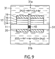
- Figures 8 and 9 are schematic sectional views showing structures of the chemical reactors 210 and 220, respectively, according to the present embodiment. The structures explained below are different from the above-described structure of the reactor 200.
- the chemical reactor 210 shown in Figure 8 comprises a photochemical reaction cell 30, an electrolytic bath 31 containing the photochemical reaction cell 30, and an opening 51 penetrating the substrate 11 to serve as the ion migration path.
- the opening 51 passes through the side edge of the substrate 11 from the oxidation electrolytic bath 31a side to the reduction electrolytic bath 31b side.
- ion-exchange membranes 43 are provided so that the oxidation and reduction bathes 31a and 31b are separated with the substrate 11 and the ion-exchange membranes 43.
- the ion-exchange membranes 43 selectively allow particular ions to pass through, and thereby the electrolyte solution is separated but at the same time only the particular ions are transferred through the membranes 43 between the bathes 31a and 31b.
- the chemical reactor 220 shown in Figure 9 comprises a photochemical reaction cell 30, an electrolytic bath 31 containing the photochemical reaction cell 30, and an opening 52 serving as the ion migration path. From the oxidation electrolytic bath 31a side to the reduction electrolytic bath 31b side, the opening 52 penetrates through a laminate of the reduction catalyst layer 20, the substrate 11, the multi-junction solar cell 17 and the oxidation catalyst layer 19.
- ion-exchange membranes 43 are provided so that the oxidation and reduction bathes 31a and 31b are separated with the substrate 11 and the ion-exchange membranes 43.
- the ion-exchange membranes 43 selectively allow particular ions to pass through, and thereby the electrolyte solution is separated but at the same time only the particular ions are transferred through the membranes 43 between the bathes 31a and 31b.
- the reactor 220 shown in Figure 9 comprises the ion-exchange membranes 43 only in a part of the opening 52, the opening 52 may be wholly filled with the membranes 43.
- the present embodiment can provide a chemical reactor of high reaction efficiency.
- the reduction catalyst of Example 1 was produced by employing Au as the substrate surface (metal layer) and aminoethanethiol as the organic modifying molecule.
- a stainless-steel substrate 150 mm x 250 mm, thickness: 150 ⁇ m
- the formed layer had a thickness even in planar direction, and the thickness was 100 nm.
- the current collector thus provided with the metal layer was immersed for 48 hours in 10 mL of a 1 mM ethanol solution of aminoethanethiol, to fix the organic modifying molecules on the metal layer.
- Example 1 The procedure of Example 1 was repeated except for employing the compounds shown in Table 1 as the modifying molecule, to produce reduction catalysts of Examples 2 to 15.
- Example 1 The procedure of Example 1 was repeated except for not employing any modifying molecule, to produce a reduction catalyst of Comparative example 1.
- Example 1 The procedure of Example 1 was repeated except for employing the compound shown in Table 1 as the modifying molecule, to produce reduction catalysts of Examples 2 to 15.
- the used modifying molecule is represented by the formula (A), but the integer "na” in the formula is out of the range according the embodiment.
- Example 1 The procedure of Example 1 was repeated except that the metal layer was made of the materials shown in Table 2, to produce reduction catalysts of Examples 16 to 25.
- Example 1 The procedure of Example 1 was repeated except that the metal layer was made of the materials shown in Table 2 and that the modifying molecule was not used, to produce reduction catalysts of Comparative examples 4 to 13.
- the reduction catalyst produced in each of Examples and Comparative examples was employed as the working electrode, and an Ag/AgCl electrode and a Pt electrode were adopted as the reference electrode and the counter electrode, respectively. They were installed in a H-shaped cell to produce a three-pole cell. The Pt electrode was placed in a cell bath separated with proton exchange membranes.
- a 5% aqueous solution of NaHCO 3 was kept bubbled with 100% CO 2 gas until the solution absorbed CO 2 in the saturation concentration.
- the CO 2 concentration was measured at the gas-inlet part and at the gas-outlet part to compare the measured values. When they reached the same values, it was judged that CO 2 dissolved in the aqueous solution reached the saturation concentration.
- the 5% NaHCO 3 aqueous solution thus prepared was adopted as both CO 2 absorber and electrolyte solution for CO 2 reduction in the three-pole cells.
- the current flowing between the working and counter electrodes was measured while constant-current electrolysis was carried out under the condition where the potential applied to the working electrode was kept -1.2 V based on Ag/AgCl.
- the electrolysis was continued for 1 hour and for 30 hours.
- the bath including the working electrode was kept bubbled with 100% CO 2 gas and simultaneously kept stirred at 750 rpm with a magnetic stirrer.
- the measurement was carried out by means of an electrochemical analyzer (Solartron cell test system [trademark], manufactured by Toyo Corporation).
- the faradaic efficiency was then calculated from the current consumed on the reduction reaction at the working electrode and from the quantitative analysis of the reduction product, and was represented by the ratio of the quantity of electricity consumed on generating the reduction product to that of inputted electricity.
- Each faradaic efficiency of individual reduction product was regarded as the selectivity thereof (%).
- the total faradaic efficiency of all the products was also calculated to obtain a CO 2 reduction ratio.
- the CO 2 reduction ratio is not 100% because the inputted electricity is partly consumed on the side reaction to generate hydrogen and also partly consumed as Joule heat.
- Table 1 shows the CO 2 reduction performance of Examples 1 to 15 and Comparative example 1.
- the reduction catalysts of Examples 16 to 25 and Comparative examples 4 to 13 were used as the reduction electrode to evaluate CO 2 reduction performance.
- the results were shown in Table 2, in which the result of Comparative example 1 was also shown for reference.
- Examples 1 to 25 showed very high values of the CO 2 reduction and of the reaction-maintaining ratio. Further, in Examples 1 to 25, ethylene glycol was produced in very high selectivity. That is thought to be because the terminal amino groups in the modifying molecules not only promote the CO 2 reduction reaction but also contribute toward improvement of the ethylene glycol selectivity. Examples individually exhibited high reduction efficiencies and high reduction reaction-maintaining ratios, as compared with Comparative examples 2 and 3. Those Comparative examples adopted modifying molecules of such large "na" integers that the basic terminals were placed at a long distance from the substrate. The reason why the CO 2 reduction in Examples could stably keep proceeding for as long as 30 hours is thought to be because the basic terminals of the modifying molecules were so near to the substrate that resistance to the reduction current could be enough lowered to inhibit the side reactions.
- Comparative examples 1 and 4 to 11 the reduction electrode was not provided with the modifying molecules. Comparative examples 1, 4, 5, 7 and 12 showed very poor CO 2 reduction performance. In Comparative examples 6, 8 to 11, and 13, the reduction electrode was not provided with the modifying molecules and the metal layer was made of Pt, Fe, Ti, Sn, In or Ni. Comparative examples 6, 8 to 11, and 13 failed to reduce CO 2 .
- the reduction catalyst of Example 26 was produced by employing Au as the substrate surface (metal layer), mercaptoethylimidazole as both spacer molecule and modifying molecule, and Au particles having a mean size of 3 nm as the metal fine particles.
- the mean size of the fine particles was measured by means of a particle size analyzer (Zetasizer Nano ZS [trademark], manufactured by Malvern Instruments Ltd.).
- a stainless-steel substrate 150 mm x 250 mm, thickness: 150 ⁇ m
- the formed layer had a thickness even in planar direction, and the thickness was 100 nm.
- the current collector thus provided with the metal layer was immersed for 48 hours in 10 mL of a 1 mM ethanol solution of mercaptoethylimidazole, to fix the organic spacer molecules on the metal layer and thereby to form an organic spacer molecule layer. Subsequently, the collector provided with the spacer layer was immersed for 12 hours in an aqueous solution in which the metal fine particles were dispersed, to fix the metal fine particles on the spacer layer. The collector loaded with the metal particles was then immersed for 48 hours in 10 mL of a 1 mM ethanol solution of mercaptoethylimidazole, to fix the modifying molecules on the metal fine particles.
- the reduction catalyst thus prepared was used as the reduction electrode and 5%NaHCO 3 aqueous solution was adopted as both CO 2 absorber and electrolyte solution for CO 2 reduction, to produce a three-pole cell in the same manner as described above.
- Example 26 The procedure of Example 26 was repeated except for adopting a triethanolamine aqueous solution (50 wt% aqueous solution, CO 2 -saturatation absorber), to produce a three-pole cell.
- a triethanolamine aqueous solution 50 wt% aqueous solution, CO 2 -saturatation absorber
- Example 26 The procedure of Example 26 was repeated except for adopting a 90% 1-ethyl-3-methylimidazolium tetrafluoroborate aqueous solution (EMIBF4, CO 2 -saturatation absorber), to produce a three-pole cell.
- EMIBF4 90% 1-ethyl-3-methylimidazolium tetrafluoroborate aqueous solution
- CO 2 -saturatation absorber a 90% 1-ethyl-3-methylimidazolium tetrafluoroborate aqueous solution
- Comparative example 1 The procedure of Comparative example 1 was repeated to prepare a reduction catalyst not comprising any of the spacer molecules, the metal fine particles and the modifying molecules.
- the prepared catalyst and a triethanolamine aqueous solution 50 wt% aqueous solution, CO 2 -saturatation absorber) were used to produce a three-pole cell in the same manner as that in Example 26.
- Comparative example 1 The procedure of Comparative example 1 was repeated to prepare a reduction catalyst not comprising any of the spacer molecules, the metal fine particles and the modifying molecules.
- the prepared catalyst and a 90% 1-ethyl-3-methylimidazolium tetrafluoroborate aqueous solution (EMIBF4, CO 2 -saturatation absorber) were used to produce a three-pole cell in the same manner as that in Example 26.
- Examples 26 to 28 showed very high values of the CO 2 reduction. Further, in Examples 26 to 28, ethylene glycol was produced in very high selectivity. This indicates that the electrolyte solution may be any of the ethylene glycol aqueous solution, amine aqueous solution and ionic liquid, and it also indicates that very efficient CO 2 reduction can proceed with high selectivity in any electrolyte solution. From the result of Example 28, it was found that the electrolyte solution of ionic liquid realizes particularly efficient CO 2 reduction.
- Example 26 The procedure of Example 26 was repeated except for adopting a multi-junction solar cell substrate as the collector and mercaptoethyltriazole as both spacer molecule and modifying molecule, to produce a reduction catalyst.
- an oxidation catalyst layer On the oxidation electrode layer in the multi-junction solar cell, an oxidation catalyst layer was formed. Specifically, the oxidation electrode layer was sprayed with a dispersion in which nanoparticles of nickel oxide were dispersed in an alcohol aqueous solution, to produce a photochemical reaction cell of Example 26. The cell was cut into a size of 150 mm x 250 mm.
- Comparative example 1 The procedure of Comparative example 1 was repeated except for adopting a multi-junction solar cell substrate as the collector, to prepare a reduction catalyst not comprising any of the spacer molecules, the metal fine particles and the modifying molecules.
- an oxidation catalyst layer On the oxidation electrode layer in the multi-junction solar cell, an oxidation catalyst layer was formed. Specifically, the oxidation electrode layer was sprayed with a dispersion in which nanoparticles of nickel oxide were dispersed in an alcohol aqueous solution, to produce a photochemical reaction cell of Comparative example 15. The cell was cut into a size of 150 mm x 250 mm.
- the photochemical reaction cells of Example 29 and Comparative example 17 were individually installed in chemical reactors and evaluated on the energy conversion efficiency.
- the oxidation-side and reduction-side electrolyte solutions were a 0.5 M potassium hydroxide (KOH) aqueous solution and a triethanolamine aqueous solution (50 wt% aqueous solution, CO 2 -saturatation absorber), respectively.
- KOH potassium hydroxide
- a triethanolamine aqueous solution 50 wt% aqueous solution, CO 2 -saturatation absorber
- proton exchange ones were used.
- the oxidation catalyst layer side of each reactor was exposed to light of AM1.5 (100 mW/cm 2 ) from a solar simulator, and CO gas generated on the reduction side and all the other CO 2 reduction products were quantitatively analyzed with a gas chromatograph and the like in the same manner as those in Example 1. From the results, values of energy conversion efficiency were calculated according to the following formula (7): FE/SE x 100 (7).
- Comparative example 15 The energy conversion efficiency in Comparative example 15 was 0.01% while that in Example 29 was 0.05%. This indicates that, if conducted by use of the reduction catalyst comprising the organic modifying molecules, the reduction reaction is driven by lower energy to improve the energy conversion efficiency.
Landscapes
- Chemical & Material Sciences (AREA)
- Organic Chemistry (AREA)
- Engineering & Computer Science (AREA)
- Chemical Kinetics & Catalysis (AREA)
- Materials Engineering (AREA)
- Electrochemistry (AREA)
- Metallurgy (AREA)
- Inorganic Chemistry (AREA)
- Catalysts (AREA)
- Electrodes For Compound Or Non-Metal Manufacture (AREA)
- Electrolytic Production Of Non-Metals, Compounds, Apparatuses Therefor (AREA)
Abstract
Description
- Embodiments of the present disclosure relate to a reduction catalyst, and a chemical reactor, a reduction method and a reduction product-producing system employing the catalyst.
- In view of energy and environmental problems, it is desired to reduce CO2 by using light energy as efficiently as plants. Plants reduce CO2 in a system referred to as "Z-scheme", which includes two-step excitation with light energy. Through photochemical reactions in this system, plants oxidize water (H2O) to obtain electrons and thereby reduce carbon dioxide (CO2) to synthesize cellulose and sugars.
- The Z-scheme in plants is nowadays mimicked to develop artificial photosynthetic systems.
- In the artificial photosynthetic systems, the electric potential necessary for reducing CO2 is obtained from visible light by use of photo-catalysts. However, the photo-catalysts are generally poor in energy efficiency and accordingly the artificial photochemical reactions, which do not adopt any sacrificial reagent, proceed in very low efficiency and hence have room for improvement. Thus, it is desired to provide a highly efficient CO2 reduction technology.
-
-
Figure 1 schematically shows a structure of the reduction catalyst according to an embodiment. -
Figure 2 schematically shows a structure of the reduction catalyst according to another embodiment. -
Figure 3 is a schematic sectional view showing a structure of the photochemical reaction cell according to an embodiment. -
Figure 4 is a schematic sectional view illustrating an example of the working principle of the photochemical reaction cell according to the embodiment. -
Figure 5 is a schematic sectional view illustrating another example of the working principle of the photochemical reaction cell according to the embodiment. -
Figure 6 is a perspective view schematically illustrating a structure of the photochemical reactor according to an embodiment. -
Figure 7 is a schematic sectional view showing a structure of the photochemical reactor according to the embodiment. -
Figure 8 is a schematic sectional view showing another structure of the photochemical reactor according to the embodiment. -
Figure 9 is a schematic sectional view showing still another structure of the photochemical reactor according to the embodiment. - The reduction catalyst according to an embodiment comprises an electric conductor and an organic layer having organic modifying groups placed on the surface of said conductor; wherein said organic modifying groups have a structure represented by the following formula (A) or (B):

- each Ra is independently H or an alkyl group of C1 to C4,
- Z is an aromatic ring having two or more nitrogen atoms,
- Y is a heteroatom-containing group capable of linking to said electric conductor layer,
- na is an integer of 1 to 5 inclusive, and
- nb is an integer of 0 to 6 inclusive.
- The chemical reactor according to another embodiment comprises
- an oxidation electrode,
- a reduction electrode provided with the above reduction catalyst, and
- a power supply unit connected to the oxidation and reduction electrodes.
- The reduction method according to still another embodiment comprises the steps of:
- bringing an electrolyte solution into contact with a reduction electrode provided with the above reduction catalyst, and then
- introducing a low molecular weight-carbon compound into the electrolyte solution so as to reduce the introduced compound by the action of said electrode.
- The reduction product-producing system according to yet another embodiment comprises: a chemical reactor which comprises an oxidation electrolytic bath provided with an oxidation catalyst and a reduction electrolytic bath provided with the above reduction catalyst, so as produce a reduction product by a reduction reaction of carbon dioxide;
- an electrolyte solution supply unit by which an electrolyte solution is supplied to the reduction electrolytic bath;
- a carbon dioxide supply unit by which carbon dioxide is dissolved in the electrolyte solution so as to keep the reduction reaction in the reduction electrolytic bath and thereby to increase the concentration of the reduction product in the electrolyte solution; and
- a separation unit by which the reduction product is separated from the electrolyte solution when the concentration thereof is increased.
- Embodiments will now be explained with reference to the accompanying drawings.
- The reduction catalyst according to the first embodiment comprises an electric conductor and an organic layer having organic modifying groups placed on the surface of the conductor.
- The reduction catalyst of the first embodiment will be explained below with reference to
Figure 1 , which schematically shows a structure of thereduction catalyst 100. As shown inFigure 1 , the reduction catalyst comprises acurrent collector 101 and organic modifyinggroups 112. Thecurrent collector 101 supports anelectric conductor 102 provided thereon. The organic modifyinggroups 112 are combined with theelectric conductor 102 to form a self-assembled monolayer (SAM) 111. Hereinafter, organic molecules giving the organic modifying groups are referred to as "organic modifying molecules". - The
current collector 101 is made of material having electroconductivity. For example, thecurrent collector 101 may be a stainless-steel substrate. Theelectric conductor 102, which is placed on the surface of thecurrent collector 101, preferably contains at least one metal selected from the group consisting of: Au, Ag, Cu, Zn, Pt, Fe, Ti, Ni, Sn, In and Bi. Theconductor 102 can contain ingredients other than metals, but preferably consists of metals only. Further, the electric conductor can be made of electroconductive metal oxides, such as, oxides selected from the group consisting of Ag2O, CuO, Ta2O5 TiO2, ZrO2, Al2O3, SiO2 ZnO, ITO, and FTO. Theelectric conductor 102 and thecurrent collector 101 may be made of the same material. In that case, the metal of theconductor 102 may serve also as thecollector 101. - The metal contained in the
electric conductor 102 functions as a catalyst activating the reduction reaction. Accordingly, the metal in theconductor 102 is preferably in the form of such fine particles as to enhance the catalytic activity. - If the
conductor 102 contains metal fine particles, the particles preferably have a mean size of 1 to 300 nm inclusive because the mean size of 300 nm or less can increase efficiency of the catalytic activity. It is, however, difficult to produce the fine particles having a mean size of less than 1 nm. The mean particle size is more preferably 150 nm or less because the catalytic activity efficiency is more increased. The metal particles either may be primary particles having a mean size of 50 nm or less, or may be secondary particles derived from aggregation of those primary particles. - The organic modifying
group 112 comprises a heteroatom-containinggroup 109 at one terminal and a nitrogen-containing group at the other terminal. InFigure 1 , the heteroatom-containing group and the nitrogen-containing group are -S- and imidazole groups, respectively. - The organic modifying group is not limited to that in
Figure 1 , and it is possible to adopt groups having a structure represented by the following formula (A) or (B):
- each Ra is independently H or an alkyl group of C1 to C4,
- Z is an aromatic ring having two or more nitrogen atoms,
- Y is a heteroatom-containing group capable of linking to the electric conductor,
- na is an integer of 1 to 5 inclusive, and
- nb is an integer of 0 to 6 inclusive.
- Since the chain of na or nb is relatively short, the reduction reaction proceeds near the
electric conductor 102. That is thought to be the reason why high reaction efficiency can be realized. - The nitrogen atom contained in the organic modifying group is presumed to capture the objective compound aimed to reduce, and accordingly the reaction efficiency also depends on the structures of substituent groups linking to the nitrogen atom
- For example, the number of carbon atoms contained in Ra of the formula (A) is preferably large to a certain degree in view of increasing acidity of the organic modifying group, but on the other hand if having many carbon atoms, Ra may be bulky to cause steric hindrance. Accordingly, Ra is limited to H or an alkyl group of C1 to C4. Further, Z necessarily contains two or more nitrogen atoms for the purpose of ensuring adequate interaction with the objective atom, and the aromatic ring thereof is preferably a 5- or 6-membered one. Examples of the organic modifying group represented by the formula (B) include groups represented by the following formula (B-1) or (B-2):

- The heteroatom-containing
group 109 inFigure 1 corresponds to Y in the formula (A) or (B). Thegroup 109 has affinity with theelectric conductor 102, and hence chemically combines therewith. The organic modifyinggroup 112 is thus fixed on theconductor 102. The heteroatom-containinggroup 109 is preferably capable of forming a covalent bond with theconductor 102. Preferred examples of thegroup 109 include groups derived from thiol, disulfide and thiocyanate groups. Specifically, the heteroatom-containinggroup 109 is preferably selected from the group consisting of -S-, -S=S- and -N=C=S-. Particularly preferred is -S- derived from thiol group because it is excellent in bonding strength. - The organic modifying
group 112 is preferably derived from an organic modifying molecule selected from the group consisting of: aminoethanethiol, aminopropanethiol, aminobutanethiol, methylaminoethanethiol, isopropylethylaminoethanethiol, dimethylaminoethanethiol, diethylaminoethanethiol, dibutylaminoethanethiol, mercaptoethylimidazole, mercaptopropylimidazole, mercaptobutylimidazole, captohexylimidazole, mercaptotriazole, mercaptoethyltriazole, mercaptopropyltriazole, mercaptobutyltriazole, and mercaptohexyltriazole. - The
reduction catalyst 100 can be produced in the following manner. - First, the
electric conductor 102 is formed on the surface of thecurrent collector 101 by a known vacuum film-forming technique, such as, sputtering, vacuum deposition or ALD (atomic layer deposition). - The heteroatom-containing
group 109 is then combined with theelectric conductor 102, so that the organic modifyinggroup 112 is fixed on theconductor 102. This procedure can be carried out in known manners. For example, thecollector 101 provided with theconductor 102 is brought into contact with a solution in which the organic modifying molecules are dissolved. The organic modifying molecules may be vaporized in high vacuum and deposited to form a film thereof on the surface of thecollector 101, or otherwise the modifying molecules may be sprayed onto the surface of thecollector 101. - When the
conductor 102 is wetted with the solution containing the modifying molecules dissolved therein, the modifyinggroups 112 are chemically adsorbed on theconductor 102 and then spontaneously form aggregates by the action of Van der Waals forces and hydrophobic interactions among the adsorbed molecules. The adsorbed molecules thus densely aggregate and consequently form an oriented monolayer. - Any solvent capable of dissolving the organic modifying molecules can be adopted to prepare the solution. For example, it can be selected from alcohols such as ethanol, aromatic organic solvents such as toluene and hexane, or aliphatic ones. Among them, ethanol is preferred because the modifying
groups 112 are well dissolved therein and it is easy to handle. - The procedure for fixing the modifying
groups 112 on theconductor 102 is, for example, carried out in the manner described below in detail. - First, the organic modifying molecules are dissolved to prepare a solution. In the prepared solution, the
collector 101 provided with theconductor 102 is then immersed for several minutes to several hours. Thus, the modifyinggroups 112 are fixed on the surface of theconductor 102. The conditions, such as, concentration of the modifying molecules, immersion time and temperature, can be adequately changed according to the structure of the modifyinggroups 112 and the like. Those conditions influence formation of the monolayer of the modifyinggroups 112. - If the prepared solution has too low a concentration, it takes long time to form the monolayer. On the other hand, however, if the concentration is too high, the molecules may be further adsorbed on the formed monolayer to form a multilayer. Accordingly, the concentration of the modifying
groups 112 is preferably 0.1 to 100 mM inclusive, more preferably 1 to 10 mM inclusive. - The immersion time is preferably long enough to form a dense and oriented monolayer, and is preferably 1 minute to 100 hours inclusive, more preferably 12 to 72 hours inclusive.
- The temperature of the solution during the immersion step influences formation of the dense and oriented monolayer. In consideration of vapor pressure, boiling point and the like of the solvent, the temperature is preferably room temperature (25°C) to 60°C inclusive.
- It can be verified by known electrochemical or surface analytical methods whether or not the modifying
groups 112 are fixed on the surface of theconductor 102. The surface analysis can be carried out with a Fouier transform infrared (FT-IR) reflection spectrophotometer. This analysis can sensitively measure IR spectra of the thin layer and the molecular species adsorbed on the surface of thecollector 101. Accordingly, the analysis can reveal the structure of the organic molecule and particularly can provide knowledge of the functional groups therein. The surface analysis also can be carried out by X-ray photoelectron spectroscopy (XPS). This analysis can determine the elemental species of the molecules. - As an example of the reaction with the
reduction catalyst 100, reduction of CO2 is then explained below. In an elementary reaction of CO2 reduction, CO2 undergoes one-electron reduction to be a CO2 radical anion. This reaction necessarily proceeds in a large overvoltage condition. However, the overvoltage condition causes energy loss, and hence lowers the energy conversion efficiency. Further, the reduction of CO2 is accompanied with that of H2O and H+ as side reactions, which result in generating H2. Accordingly, the side reactions decrease the faradaic efficiency of the CO2 reduction reaction. Despite those, thereduction catalyst 100 according to the embodiment can realize high reduction efficiency. - The
reduction catalyst 100 contains a nitrogen-containing group, which has such high affinity with CO2 as to contribute toward generation and stabilization of a CO2 radical anion. Further, the nitrogen-containing group reacts with a CO2 molecule to form a carbonate. The nitrogen-containing groups thus attract CO2 molecules necessary for the reduction reaction, and then form salts with resultant carboxylic acids (such as, formic acid, acetic acid, oxalic acid) produced by the CO2 reduction. Because of that, the catalyst has an effect of promoting a multielectron reduction reaction in which the reduction proceeds continuously. In this way, thereduction catalyst 100 makes it possible to improve the reduction efficiency and hence can cause the CO2 reduction reaction with low energy. As a result, the reduction catalyst can improve the energy conversion efficiency. Further, the monolayer densely combined with theconductor 102 has an effect of preventing H2O and H+ from approaching the conductor, and hence provides reaction selectivity of reduction on theconductor 102. This means that the monolayer can inhibit generation of H2 caused by the side reactions and accordingly can improve the faradaic efficiency. - For the reasons described above, the present embodiment can provide a reduction catalyst of high reaction efficiency.
- The reduction catalyst according to the embodiment can be applied to reduction of a material selected from the group consisting of carbon dioxide, oxalic acid and glyoxal. Reduction products depend on interactions among the organic modifying molecule, the
conductor 102 and the material aimed to reduce. For example, when CO2 is reduced, formable reduction products are carbon monoxide (CO), formic acid (HCOOH), formic aldehyde (HCHO), methanol (CH3OH), acetic acid (CH3COOH), acetaldehyde (CH3CHO), ethanol (CH3CH2OH), oxalic acid ((COOH)2), glyoxal and ethylene glycol (HOCH2CH2OH). - Among the above, the
reduction catalyst 100 of the present embodiment can produce ethylene glycol in high selectivity. It becomes, therefore, possible to provide a reduction catalyst-application process in which thereduction catalyst 100 is used to reduce a material selected from the group consisting of carbon dioxide, oxalic acid and glyoxal and thereby to produce products including ethylene glycol. -
Figure 2 schematically shows the structure of areduction catalyst 150 according to the present embodiment. As shown inFigure 2 , thereduction catalyst 150 comprises acurrent collector 101 provided with anelectric conductor 102, a spacerorganic molecule layer 105 formed on the surface of theconductor 102, metalfine particles 107 linked to the surface of the spacerorganic molecule layer 105, and organic modifyinggroups 112 combined with the metalfine particles 107. In this embodiment, the metalfine particle 107 functions as the electric conductor. Thus, this embodiment comprises two kind of the electric conductor. - The
collector 101 and theconductor 102 may be the same as those in the first embodiment. - The spacer
organic molecule layer 105 is a self-assembled monolayer formed through a process in which spacergroups 106 derived from spacer organic molecules are adsorbed and then self-assembled on the surface of theconductor 102. - The
spacer group 106 comprises, for example, analkylene skeleton 106A, a first reactivefunctional group 106B positioned at one terminal, and a second reactivefunctional group 106C positioned at the other terminal. - In accordance with increase of the chain length in the
spacer group 106, the density and orientation are enhanced in the formed monolayer. Because of that, according as the chain length is extended, the metalfine particles 107 becomes easy to fix and the monolayer becomes highly durable. However, if the chain is too long, the spacerorganic molecule layer 105 has such large tunnel current resistance as to increase electrode resistance of thereduction catalyst 150. Accordingly, thespacer group 106 contains preferably 2 to 12, more preferably 2 to 6 carbon atoms in total. - The first reactive
functional group 106B has affinity with theelectric conductor 102, and hence chemically combines therewith. Theorganic spacer group 106 is thus fixed on theconductor 102. The first reactivefunctional group 106B is preferably capable of forming a covalent bond with theconductor 102. Preferred examples of thegroup 106 include groups derived from thiol, disulfide and thiocyanate groups. Specifically, thegroup 106B is preferably selected from the group consisting of -S-, -S=S- and -N=C=S-. Particularly preferred is -S- derived from thiol group because it is excellent in bonding strength. - The second reactive
functional group 106C has affinity with the metalfine particle 107, and hence chemically combines therewith. Theparticle 107 is thus fixed on the spacerorganic molecule layer 105. The second reactivefunctional group 106C is preferably capable of forming an electrostatic bond with theparticle 107 charged electrically, and preferred examples thereof include amino group and carboxyl group. Instead, the second reactivefunctional group 106C is preferably capable of forming a covalent bond with theparticle 107, and preferred examples thereof include groups derived from thiol, disulfide and thiocyanate groups. - Examples of spacer organic molecules capable of forming the
spacer layer 105 include the same molecules as those giving the organic modifyinggroup 112 described above in the first embodiment. In addition, the examples further include such molecules as: 10-carboxy-1-decanethiol, 7-carboxy-1-heptanethiol, 5-carboxy-1-pentanethiol, 3-carboxy-1-pentanethiol, mercaptoacetic acid, 10-carboxydecyl disulfide, 7-carboxyheptyl-disulfide, 5-carboxypentyl-disulfide, 4,4'-dithiodibutanoic acid, 11-amino-1-undecanethiol, 8-amino-1-octanethiol, 1,2-ethanedithiol, 1,3-propanedithiol, 1,4-butanedithiol, 1,5-pentanedithiol, 1,6-hexanedithiol, 1,7-heptanedithiol, 1,8-octanedithiol, 1,9-nonanedithiol, 1,10-decanedithiol, 1,11-undecanedithiol, 1,12-dodecanedithiol, 1,13-tridecanedithiol, 1,14-tetradecanedithiol, 1,15-pentadecanedithiol, and 1,16-hexadecanedithiol. - The metal
fine particles 107 function as a catalyst activating the reduction reaction. They are made of at least one element selected from the group consisting of Au, Ag, Cu, Pt, Zn, Fe, Ti, Sn, Bi and Ni. Thefine particles 107 are preferably those of Au or Ag because they have high catalytic activity. - The
metal particles 107 preferably have a mean size of 1 to 300 nm inclusive because the mean size of 300 nm or less can increase the efficiency of the catalytic activity. It is, however, difficult to produce theparticles 107 having a mean size of less than 1 nm. The mean particle size is more preferably 150 nm or less because the efficiency of catalytic activity is more increased. Themetal particles 107 either may be primary particles having a mean size of 50 nm or less, or may be secondary particles derived from aggregation of those primary particles. - The mean size of the
particles 107 can be determined according to particle size distribution measurement by dynamic light scattering. Specifically, thefine particles 107 are dispersed in a solution and then laser beams are applied to the dispersion to detect fluctuating scattered light. The fluctuation of scattered light suggests the diffusion coefficient, and hence the particle size can be calculated from the result according to the Stokes-Einstein equation. How frequently the particles of each size are thus detected is integrated to obtain a frequency distribution, in which the most frequent size or the size giving the maximum frequency is the mode size of the distribution. The mode size is regarded as the mean particle size. - The metal
fine particle 107 may have an electrically chargedorganic molecule 108 on a part of the surface. Thatparticle 107 consequently has an electrically charged surface. The charge on theparticle 107 can be so controlled that theparticle 107 can be fixed on the spacerorganic molecule layer 105 through electrostatic attraction (electrostatic attraction bond) to the charge of the second reactivefunctional group 106C. Theorganic molecule 108 may be charged either positively or negatively. - If the organic molecule has negative charge, the surface of the
particle 107 is negatively charged. In that case, the spacerorganic molecule 106 is so selected as to have an amino group as the second reactivefunctional group 106C for fixing theparticle 107. - On the other hand, if the organic molecule is charged positively, the
spacer molecule 106 is so selected as to have a carboxyl group as the second reactivefunctional group 106C for fixing theparticle 107. - If the
fine particles 107 are thus electrically charged, they electrostatically repel each other and hence can be prevented from gathering to form aggregates of nanosize particles. - The organic modifying
group 112 is linked to theparticle 107, and has an effect of promoting the reduction reaction. The modifyinggroup 112 can be the same as that in the first embodiment. The heteroatom-containinggroup 109 in the modifyinggroup 112 has affinity with theparticle 107, and hence chemically combines therewith. The modifyinggroup 112 is thus fixed on the metalfine particle 107. In this embodiment, the metal fine particles are loaded on a spacer layer that is made of organic material and formed on another electric conductor on a current collector. - The
reduction catalyst 150 can be produced in the following manner. - First, the
electric conductor 102 is formed on the surface of thecurrent collector 101 by a known vacuum film-forming technique, such as, sputtering, vacuum deposition or ALD (atomic layer deposition). Thespacer groups 106 are then fixed on theconductor 102 to form the spacerorganic molecule layer 105. This procedure can be carried out in the same manner as that for fixing the modifyinggroups 112 on theconductor 102 in a production process of thereduction catalyst 100 according to the first embodiment. - It can be verified whether or not the
spacer layer 105 is formed on theconductor 102 also in the same manner as that for verifying whether or not the modifyinggroups 112 are fixed on theconductor 102 in a production process of thereduction catalyst 100 according to the first embodiment. - Thereafter, the metal
fine particles 107 are prepared. If necessary, theorganic molecule 108 is fixed on the particle. This procedure can be carried out in the following first or second manner. - In a first process for preparing the metal fine particles, a reducing agent such as citric acid is employed to conduct reduction when metal fine particles are obtained from a liquid phase. The agent such as citric acid is attached on the surface of the particle thus obtained, and thereby the surface is negatively charged. Successively, the negatively charged surface is electrostatically combined with a molecule having an amino group.
- In order to positively charge the metal fine particle, an uncharged surface of the particle is combined with an amine molecule having a covalent reactive group such as thiol. This process makes it possible to fix a charged organic molecule whether the particle surface is charged positively, negatively or not.
- In the next step, the metal
fine particles 107 loaded with the chargedorganic molecules 108 are fixed on the surface of the spacerorganic molecule layer 105. Specifically, theparticles 107 are dispersed in a disperse medium to prepare a dispersion, in which thecollector 101 provided with thespacer layer 105 formed thereon is then immersed. Thus, the secondreactive group 106C in thespacer layer 105 is electrostatically combined with theorganic molecules 108 on theparticle 107 and thereby theparticle 107 is fixed on thespacer layer 105. - The disperse medium in which the
particles 107 are dispersed is not particularly restricted as long as it can stably disperse the particles. Examples thereof include water, ethanol and toluene, and preferred are water and ethanol because they are easy to handle. - The dispersion conditions, such as, concentration, immersion time and temperature, are adequately determined because they depend on the synthesis method and stability of the metal
fine particles 107. - If the dispersion has too low a concentration, it takes long time to fix the
particles 107. However, if the concentration is too high, there is a fear that theparticles 107 may aggregate and fail to fix on thespacer layer 105. Accordingly, the concentration of the particles in the dispersion is preferably 0.01 to 10 mM inclusive, more preferably 0.1 to 1 mM inclusive. - The immersion time is preferably 1 to 50 hours inclusive, more preferably 5 to 24 hours inclusive so that the
particles 107 can be fixed in a sufficient amount. - The dispersion temperature during the immersion step is preferably room temperature (25°C) to 35°C inclusive. At a high temperature, there is a fear that the dispersion stability of the
particles 107 is so lowered that they may aggregate. - It can be verified by known electrochemical or surface analytical methods whether or not the
particles 107 are fixed on the surface of thespacer layer 105. - In the surface analysis, it can be directly observed by means of a scanning electron microscope (SEM), a transmission electron microscope (TEM), an atomic force microscope (AFM), or a scanning transmission microscope (STEM). Further, the metal composition can be analyzed according to, for example, energy dispersive X-ray spectrometry (EDX), electron probe microanalysis (EPMA) or X-ray photoelectron spectroscopy (XPS).
- Subsequently, the organic modifying
group 112 is combined with theparticle 107 fixed on thespacer layer 105. This procedure can be carried out in the same manner as that for fixing the modifyinggroups 112 on theconductor 102 in a production process of thereduction catalyst 100 according to the first embodiment. - The procedure for fixing the modifying
group 112 on theparticle 107 is, for example, carried out in the manner described below in detail. - First, the organic modifying molecules are dissolved to prepare a solution containing the modifying
groups 112 dissolved therein. In the prepared solution, thecollector 101 provided with the metalfine particles 102 is then immersed for several minutes to several hours. Thus, the modifyinggroups 112 are fixed on the surface of theparticles 107. The conditions, such as, concentration of the modifying groups, immersion time and temperature, can be adequately changed according to the structure of the modifyinggroups 112 and the like. - If the prepared solution has too low a concentration, it takes long time to fix the modifying
groups 112 in a sufficient amount. On the other hand, however, if the concentration is too high, the modifyinggroups 112 may be excessively adsorbed to accumulate. Accordingly, the concentration of the modifyinggroups 112 is preferably 0.1 to 100 mM inclusive, more preferably 1 to 10 mM inclusive. - The immersion time is preferably long enough to form a dense and oriented monolayer, and is preferably 1 minute to 100 hours inclusive, more preferably 12 to 72 hours inclusive.
- The prepared solution temperature during the immersion step influences formation of the dense and oriented monolayer. In consideration of vapor pressure, boiling point and the like of the solvent, the temperature is preferably room temperature (25°C) to 60°C inclusive.
- In this way, the
reduction catalyst 150 can be produced. - As an example of the reaction with the
reduction catalyst 150, reduction of CO2 is then explained below. As described in the first embodiment, the elementary reaction of normal CO2 reduction has a problem of low faradaic efficiency. However, thereduction catalyst 150 according to the present embodiment can realize high reduction efficiency. - In the
reduction catalyst 150, the reduction reaction proceeds at the metalfine particle 107, where the modifyinggroups 112 reacts with CO2 to form a reaction intermediate. The catalyst thus contributes toward generation and stabilization of a CO2 radical anion, and hence can cause the CO2 reduction reaction with low energy. As a result, the reduction catalyst can improve the energy conversion efficiency. Further, the monolayer has an effect of preventing H2O and H+ from approaching theparticles 107, and hence provides reaction selectivity of reduction on theparticles 107. This means that the monolayer can inhibit generation of H2 caused by the side reactions, and accordingly can improve the faradaic efficiency. Further, the amino group in the modifyinggroup 112 reacts with a CO2 molecule to form a carbonate. The amino groups thus attract CO2 molecules necessary for the reduction reaction, and provide them to the metalfine particles 107. In addition, the amino groups form salts with resultant carboxylic acids (such as, formic acid, acetic acid, oxalic acid) produced by the CO2 reduction. Because of that, the catalyst has an effect of promoting a multielectron reduction reaction in which the reduction proceeds continuously. As a result, the reduction catalyst can improve the energy conversion efficiency. - Furthermore, since comprising the metal
fine particles 107, thereduction catalyst 150 can have a larger reaction area (surface area) than a tabular metal layer. Accordingly, the reduction efficiency can be further improved. - For the reasons described above, the present embodiment can provide a reduction catalyst of high reaction efficiency.
- The
reduction catalyst 150 according to the embodiment can be applied to reduction of a material selected from the group consisting of carbon dioxide, oxalic acid and glyoxal. Reduction products depend on interactions among the organic modifying molecules, theconductor 102 and the material aimed to reduce. For example, when CO2 is reduced, formable reduction products are carbon monoxide (CO), formic acid (HCOOH), formic aldehyde (HCHO), methanol (CH3OH), acetic acid (CH3COOH), acetaldehyde (CH3CHO), ethanol (CH3CH2OH), oxalic acid ((COOH)2), glyoxal and ethylene glycol (HOCH2CH2OH). - Among the above, the
reduction catalyst 150 of the present embodiment can produce ethylene glycol in high selectivity. It becomes, therefore, possible to provide a reduction catalyst-application process in which thereduction catalyst 150 is used to reduce a material selected from the group consisting of carbon dioxide, oxalic acid and glyoxal and thereby to produce products including ethylene glycol. - As the third embodiment, the following describes a chemical reactor employing the reduction catalyst according to the first embodiment. Although the explanation is omitted, the reduction catalyst according to the second embodiment also can be used in place of that of the first embodiment.
- The chemical reactor comprises a photochemical reaction cell, which is explained below with referring to
Figures 3 to 5 . The photochemical reaction cell comprises an oxidation catalyst layer, a reduction catalyst layer containing the reduction catalyst, and a power supply unit connected to the oxidation and reduction catalyst layers. The power supply unit preferably comprises a semiconductor layer in which charge separation is caused by light energy, and is preferably a solar cell, for example. The semiconductor layer is preferably placed between the oxidation and reduction catalyst layers. -
Figure 3 is a sectional view schematically showing the structure of aphotochemical reaction cell 30. As shown inFigure 3 , thereaction cell 30 is a laminate in which areduction catalyst layer 20, asubstrate 11, areflection layer 12, areduction electrode layer 13, a multi-junctionsolar cell 17, anoxidation electrode layer 18 and anoxidation catalyst layer 19 are stacked in this order. In thereaction cell 30, thereduction catalyst layer 20 is placed on the back side and theoxidation catalyst layer 19 is placed on the top side exposed to light. - The
substrate 11 is provided for the purposes of supporting the photochemical reaction cell and of enhancing mechanical strength thereof. It is, for example, a plate made of a metal selected from the group consisting of Au, Ag, Cu, Pt, Zn, Fe, Ti, Sn, In, Bi and Ni or of an alloy containing at least one of them. The alloy plate is, for example, a plate of SUS. Thesubstrate 11 also can be made of electroconductive resins, semiconductors such as Si and Ge, or ion-exchange membranes. - The
reflection layer 12 is formed on the surface of thesubstrate 11, and is made of a material capable of reflecting light. For example, it may be a distributed Bragg reflector comprising a metal layer or a semiconductor multilayer. Thereflection layer 12 is placed between thesubstrate 11 and the multi-junctionsolar cell 17, and hence can reflect light not absorbed by thesolar cell 17 so that the light can reenter thesolar cell 17. Thereflection layer 12 thus can enhance light absorption of thesolar cell 17. - The
reduction electrode layer 13 is placed on thereflection layer 12, and sandwiched between thereflection layer 12 and an n-type semiconductor layer (n-typeamorphous silicon layer 14a, described later) in thesolar cell 17. Accordingly, thereduction electrode layer 13 is preferably made of a material capable of having ohmic contact with the n-type semiconductor layer. For example, theelectrode layer 13 is made of a metal such as Au, Ag, Al or Cu or made of an alloy containing at least one of them. Thereduction electrode layer 13 may be made of a transparent electroconductive oxide, such as, ITO (indium tin oxide), zinc oxide (ZnO), FTO (fluorine-doped tin oxide), AZO (aluminum-doped zinc oxide) or ATO (antimony-doped tin oxide). Further, theelectrode layer 13 also may have a structure, for example, in which a metal and a transparent electroconductive oxide are laminated, in which a metal and another electroconductive material are combined, or in which a transparent electroconductive oxide and another electroconductive material are combined. - The multi-junction
solar cell 17 is placed on thereduction electrode layer 13, and is a laminate in which a firstsolar cell 14, a secondsolar cell 15 and a thirdsolar cell 16 are stacked in this order from theelectrode layer 13 side. All of those cells employ pin-junction semiconductors. The first, second and thirdsolar cells solar cell 17 can absorb sunlight in a wide wavelength range. Thus, it becomes possible to utilize solar energy efficiently. Further, since the solar cells are connected in series, it is possible to obtain a high open circuit voltage. - The first
solar cell 14 comprises an n-type amorphous silicon (a-Si)layer 14a, an intrinsic amorphous silicon germanium (a-SiGe)layer 14b, and a p-type fine-crystalline silicon (µc-Si)layer 14c stacked in the order from theelectrode layer 13 side. Thea-SiGe layer 14b absorbs light in a short wavelength region around 400 nm. Accordingly, in the firstsolar cell 14, charge separation is caused by light energy in the short wavelength region. - The second
solar cell 15 comprises an n-type a-Si layer 15a, an intrinsica-SiGe layer 15b, and a p-type µc-Si layer 15c stacked in the order from theelectrode layer 13 side. Thea-SiGe layer 15b absorbs light in an intermediate wavelength region around 600 nm. Accordingly, in the secondsolar cell 15, charge separation is caused by light energy in the intermediate wavelength region. - The third
solar cell 16 comprises an n-type a-Si layer 16a, an intrinsica-SiGe layer 16b, and a p-type µc-Si layer 16c stacked in the order from theelectrode layer 13 side. Thea-SiGe layer 16b absorbs light in a long wavelength region around 700 nm. Accordingly, in the thirdsolar cell 16, charge separation is caused by light energy in the long wavelength region. - In the multi-junction
solar cell 17, charge separation is thus caused by light in each wavelength region and consequently positive holes and electrons are separated and moved to the positive electrode side (top side) and to the negative electrode side (back side), respectively. In this way, the multi-junctionsolar cell 17 generates electromotive force. - The above explains the multi-junction
solar cell 17 comprising a laminate of three solar cells, but the present embodiment is not limited to the above. For example, it is possible to adopt a multi-junction solar cell comprising a laminate of two, four or more solar cells. Further, in place of the multi-junctionsolar cell 17, the embodiment may employ a single solar cell. Furthermore, although the solar cells described above comprise pin-junction semiconductors, the embodiment may employ a solar cell of pn-junction semiconductors. The solar cell may comprise a semiconductor layer of, for example, GaAs, GaInP, AlGaInP, CdTe or CuInGaSe, and the semiconductors may be in any form, such as, single crystal, multicrystal or amorphous. - The
oxidation electrode layer 18 is placed on the multi-junctionsolar cell 17, and sandwiched between the p-type semiconductor layer in thesolar cell 17 and theoxidation catalyst layer 19. Accordingly, theoxidation electrode layer 18 is preferably made of a transparent material capable of having ohmic contact with the p-type semiconductor layer. For example, theelectrode layer 18 is made of a transparent electroconductive oxide, such as, ITO (indium tin oxide), zinc oxide (ZnO), FTO (fluorine- doped tin oxide), AZO (aluminum-doped zinc oxide) or ATO (antimony-doped tin oxide). Theelectrode layer 18 may have a structure, for example, in which a metal and a transparent electroconductive oxide are laminated, in which a metal and another electroconductive material are combined, or in which a transparent electroconductive oxide and another electroconductive material are combined. - The
oxidation catalyst layer 19 is placed on the positive electrode side of the multi-junctionsolar cell 17, and is formed on theoxidation electrode layer 18. When the electrolyte solution has a hydrogen ion concentration of less than 7 (pH < 7), theoxidation catalyst layer 19 oxidizes H2O to generate O2 and H+. On the other hand, however, it oxidizes OH- to generate O2 and H2O when the electrolyte solution has a hydrogen ion concentration of more than 7 (pH > 7). Accordingly, thecatalyst layer 19 is made of a material lowering activation energy of the oxidation reaction, that is, a material lowering overvoltage of the reaction in which H2O or OH- is oxidized to extract electrons. - Examples of the material include: binary metal oxides, such as, manganese oxide (Mn-O), iridium oxide (Ir-O), nickel oxide (Ni-O), cobalt oxide (Co-O), iron oxide (Fe-O), Tin oxide (Sn-O), indium oxide (In-O) and ruthenium oxide (Ru-O); ternary metal oxides, such as, Ni-Co-O, La-Co-O, Ni-La-O and Sr-Fe-O; quaternary metal oxides, such as, Pb-Ru-Ir-O and La-Sr-Co-O; and metal complexes, such as, Ru complexes and Fe complexes.
- The
oxidation catalyst layer 19 is in the form not restricted to a thin film, and may be in the form of, for example, a grid, particles or a wire. - In the
photochemical reaction cell 30, incident light comes through theoxidation catalyst layer 19 and theoxidation electrode layer 18 and then reaches to the multi-junctionsolar cell 17. Accordingly, thecatalyst layer 19 and theelectrode layer 18 are transparent to the incident light. Specifically, they are so transparent that the light can pass in an amount of 10% or more, preferably 30% or more. - The
reduction catalyst layer 20 is placed on the negative electrode side of the multi-junctionsolar cell 17, and is formed on the back surface of thesubstrate 11. Thereduction catalyst layer 20 reduces a material aimed to reduce, such as CO2, and thereby generates carbon compounds (e.g., carbon monoxide, formic acid, formic aldehyde, methane, methanol, acetic acid, acetaldehyde, ethanol, ethylene glycol). Accordingly, thecatalyst layer 20 is made of a material lowering activation energy for reducing the material aimed to reduce. - As the
reduction catalyst layer 20 described above, thereduction catalyst 100 of the first embodiment is employed. This means that thereduction catalyst layer 20 comprises thecurrent collector 101 and the organic modifyinggroups 112 having quaternary nitrogen cations. Thecollector 101 may serve as thesubstrate 11. - There may be an electroconductive protective layer on the surface of the multi-junction
solar cell 17 or between the electrode layer and the catalyst layer on the light-incident side (i.e., between theoxidation electrode layer 18 and theoxidation catalyst layer 19 in the photochemical reaction cell 30). The protective layer protects thesolar cell 17 from corrosion in the oxidation-reduction reaction, and consequently can extend the working lifetime of thesolar cell 17. If necessary, the protective layer may be transparent. Examples of the protective layer include: dielectric thin films of TiO2, ZrO2, Al2O3, SiO2 and HfO2. The protective layer has a thickness of preferably 10 nm or less, more preferably 5 nm or less so as to ensure electric conductivity based on tunneling effect. -
Figures 4 and5 are schematic sectional views illustrating the working principle of thephotochemical reaction cell 30. In those figures, thereflection layer 12, thereduction electrode layer 13 and theoxidation electrode layer 18 are omitted. - As shown in
Figures 4 and5 , when coming from the top side, incident light (L) passes through theoxidation catalyst layer 19 and reaches to the multi-junctionsolar cell 17. Thesolar cell 17 absorbs the light to generate photoexcited electrons and their counterpart positive holes, which are then separated. Specifically, in each of the solar cells (i.e., first, second and thirdsolar cells reduction catalyst layer 20 side) while the holes counterpart to the photoexcited electrons move to the p-type semiconductor layer side (oxidation catalyst layer 19 side). Because of charge separation thus caused, the multi-junctionsolar cell 17 generates electromotive force. - The photoexcited electrons generated in the
solar cell 17 are used in the reduction reaction on thereduction catalyst layer 20 serving as the negative electrode. On the other hand, the positive holes are used in the oxidation reaction on theoxidation catalyst layer 19 serving as the positive electrode. -
Figure 4 shows an example when the electrolyte solution is an acidic solution, which has a hydrogen ion concentration of less than 7. The following reaction (1) proceeds near theoxidation catalyst layer 19, so that H2O is oxidized to generate H+, O2 and electrons. The generated H+ moves to thereduction catalyst layer 20 side by way of the ion migration path described later. Meanwhile, the following reaction (2) proceeds near thereduction catalyst layer 20, so that CO2 is reduced by the transferred H+ and electrons to generate carbon monoxide (CO) and H2O.
4H2O → 4H+ + O2 + 4e- (1)
2CO2 + 4H+ + 4e- → 2CO + 2H2O (2)
-
Figure 5 shows an example when the electrolyte solution is a basic solution, which has a hydrogen ion concentration of more than 7. The following reaction (3) proceeds near theoxidation catalyst layer 19, so that OH- is oxidized to generate O2, H2O and electrons. Meanwhile, the following reaction (4) proceeds near thereduction catalyst layer 20, so that both CO2 and H2O receive the electrons and are thereby reduced to generate carbon monoxide (CO) and OH-. The OH- generated on thereduction catalyst layer 20 side moves to theoxidation catalyst layer 19 side by way of the ion migration path described later.
40H- → O2 + 2H2O + 4e- (3)
2CO2 + 2H2O + 4e- → 2CO + 4OH- (4)
The multi-junctionsolar cell 17 necessarily has an open circuit voltage not less than the difference between the standard potential of oxidation on theoxidation catalyst layer 19 and that of reduction on thereduction catalyst layer 20. For example, when the reaction solution has a hydrogen ion concentration of 0 (pH= 0), the standard potential of oxidation in the formula (1) is +1.23 V while that of reduction in the formula (2) is -0.1 V. Accordingly, the multi-junctionsolar cell 17 must have an open circuit voltage of 1.33 V or more. - The open circuit voltage is more preferably required to be not less than the potential difference including the overvoltage. Specifically, if there is an overvoltage of 0.2 V in each of the oxidation and reduction in the formulas (1) and (2), respectively, the open circuit voltage is preferably 1.73 V or more.
- Although the above formulas (2) and (4) indicate reduction of CO2 into CO, the reduction reaction is not limited to that. For example, it is possible to reduce CO2 into HCOOH, HCHO, CH4, CH3OH, HOCH2CH2OH and the like. Any of those consumes H+ or generates OH-, and hence the total reaction efficiency is lowered if H+ generated on the
oxidation catalyst layer 19 cannot move to the counterreduction catalyst layer 20 or if OH- generated on thereduction catalyst layer 20 cannot move to the counteroxidation catalyst layer 19. In view of that, the chemical reactor according to the present embodiment is provided with an ion migration path through which H+ or OH-can be transferred. The reactor can be thus improved in the migration of H+ or OH-. In this way, the present embodiment can realize high photoreaction efficiency. - The chemical reactor comprising the above photochemical reaction cell is then explained below with referring to
Figures 6 to 9 . As an example, the oxidation-reduction reaction in the following explanation is thought to proceed under the condition where the electrolyte solution has a hydrogen ion concentration of less than 7, that is, where the solution is acidic (i.e., the reaction corresponds to the formulas (1) and (2)). If the electrolyte solution has a hydrogen ion concentration of more than 7, that is, if the solution is basic, the oxidation-reduction reaction proceeds according to the formulas (3) and (4). -
Figure 6 is a perspective view schematically illustrating a structure of thephotochemical reactor 200 according to the present embodiment, andFigure 7 is a schematic sectional view showing a structure of thereactor 200. Thereactor 200 comprises: aphotochemical reaction cell 30, anelectrolytic bath 31 containing the photochemical reaction cell, and an electrolyticbath flow channel 41 serving as the ion migration path linked to thebath 31. InFigure 6 , the ion migration path is omitted. As described above, thephotochemical reaction cell 30 comprises a laminate of theoxidation catalyst layer 19, thereduction catalyst layer 20, the multi-junctionsolar cell 17 sandwiched between them, and thesubstrate 11. - The
electrolytic bath 31 comprises an oxidationelectrolytic bath 31a provided with theoxidation catalyst layer 19 and a reductionelectrolytic bath 31b provided with thereduction catalyst layer 20. In the oxidationelectrolytic bath 31a, H2O is oxidized by thecatalyst layer 19 to generate O2 and H+. In the reductionelectrolytic bath 31b, CO2 is reduced by thecatalyst layer 20 to generate CO and H2O. Those electrolytic bathes are separated with thesubstrate 11 of thephotochemical reaction cell 30. In the present example, thesubstrate 11 is larger than thesolar cell 17 and the catalyst layers 19 and 20 and hence the side ends of the substrate protrudes from both sides. However, this example by no means restricts thesubstrate 11, and all of thesubstrate 11, thesolar cell 17 and the catalyst layers 19 and 20 may be the same size tabular plates. - It is possible to supply different electrolyte solutions to the oxidation and reduction
electrolytic bathes flow channel 41, which enables ions to migrate, connects thebathes - The
flow channel 41 thus enables H+ generated on theoxidation catalyst layer 19 side to migrate to thereduction catalyst layer 20 side, and hence CO2 can be decomposed with the transferred H+ on thereduction catalyst layer 20 side. In this way, the present embodiment can realize high photoreaction efficiency. - The electrolytic
bath flow channel 41 is then explained below in detail. Theflow channel 41 is, for example, provided on the side of theelectrolytic bath 31. One end of thechannel 41 is connected to the oxidationelectrolytic bath 31a and the other is connected to thereduction bath 31b. Theflow channel 41 thus connects theoxidation bath 31a with thereduction bath 31b, and thereby it enables ions to move between the catalyst layers 19 and 20. In a part of theflow channel 41, ion-exchange membranes 43 are provided. The ion-exchange membranes 43 selectively allow particular ions to pass through, and thereby the electrolyte solution is separated and at the same time only the particular ions are transferred between thebathes - The ion-
exchange membranes 43 are proton exchange ones, and can transfer H+ generated in theoxidation bath 31a to thereduction bath 31b. Examples of the proton exchange membranes include: cation exchange membranes, such as, Nafion and Flemion; and anion exchange membranes, such as, Neosepta and Selemion. - The ion-
exchange membranes 43 may be replaced with, for example, a salt bridge made of a material, such as agar, capable of transferring ions and of separating the electrolyte solution. However, the proton exchange membranes of solid polymer, such as Nafion, generally can improve the ion mobility. - The
flow channel 41 may be equipped with acirculation mechanism 42, such as, a pump. Thecirculation mechanism 42 promotes circulation of the electrolyte solution so as to enhance circulation of ions (H+) between thebathes bath flow channels 41. In that case, thecirculation mechanism 42 is installed in at least one channel. For example, ions are transferred with themechanism 42 through one of thechannels 41 from theoxidation bath 31a to thereduction bath 31b and through theother channel 14 from thereduction bath 31b to theoxidation bath 31a. Theflow channel 41 may be equipped with two ormore circulation mechanisms 42. Further, for the purposes of lowering diffusion of ions and thereby of circulating them efficiently, there may be a plural number (three or more) offlow channels 41. - Since making flow of the solution, the
circulation mechanism 42 can prevent bubbles of generated gases from remaining on the surfaces of the electrodes and bathes and hence from scattering the sunlight to lower the efficiency and to change the light quantity distribution. - When irradiated with light, the surface of the multi-junction
solar cell 17 may be heated to cause thermal difference in the electrolyte solution. The thermal difference can be utilized to cause convection by which ions are efficiently circulated. In this case, circulation of ions can be promoted more than diffusion thereof. - The
flow channel 41 or theelectrolytic bath 31 may be equipped with athermostat mechanism 44 for controlling the electrolyte solution temperature. Thethermostat 44 can adjust the temperature so as to control performances of the solar cell and the catalysts. For example, the reaction system can be made thermally homogeneous to improve and stabilize the performances of the solar cell and the catalysts. Further, the temperature can be prevented from rising to stabilize the system. Furthermore, the temperature can be so controlled as to change selectivity of the solar cell and the catalysts and thereby to control the reaction products. - The oxidation
electrolytic bath 31a is filled with an electrolyte solution containing desired electrolytes. Theoxidation catalyst layer 19 is immersed in the electrolyte solution. The electrolyte solution preferably promotes the oxidation reaction of H2O and is, for example, a liquid containing H2O. - The reduction
electrolytic bath 31b is filled with an electrolyte solution containing desired electrolytes. Thereduction catalyst layer 20 is immersed in the electrolyte solution. It is preferred for the electrolyte solution to lower the reduction potential of CO2 to have high ion conductivity and to contain a CO2 absorber capable of absorbing CO2. The electrolyte solution is, for example, a liquid containing CO2. Examples of the electrolyte solution loaded in thereduction bath 31b include: an ionic liquid which consists of a cation such as imidazolium or pyridinium ion and an anion such as BF4 - or PF6 -and which can be in a liquid state in a wide temperature range; an amine solution such as ethanolamine, imidazole or pyridine solution; and an aqueous solution thereof. The amine may be either primary, secondary or tertiary. Examples of the primary amine include: methylamine, ethylamine, propylamine, butylamine, pentylamine, and hexylamine. In any of the primary, secondary and tertiary amine, the hydrocarbon group substituted with amine may be alcohol or may be substituted with halogens. Examples thereof include methanolamine, ethanolamine, and chloromethylamine. The hydrocarbon group substituted with amine may have an unsaturated bond. - Examples of the secondary amine include: dimethylamine, diethylamine, dipropylamine, dibutylamine, dipentylamine, dihexylamine, dimethanolamine, diethanolamine, dipropanolamine, methylethylamine, and methylpropylamine.
- Examples of the tertiary amine include: trimethylamine, triethylamine, tripropylamine, tributylamine, trihexylamine, trimethanolamine, triethanolamine, tripropanolamine, tributanolamine, tripentanolamine, trihexanolamine, methyldiethylamine, and methyldipropylamine.
- The ionic liquid can comprise a cation such as imidazolium or pyridinium ion. Examples of the imidazolium ion include: 1-ethyl-3-methylimidazolium ion, 1-methyl-3-propylimidazolium ion, 1-butyl-3-methylimidazole ion, 1-methyl-3-pentylimidazolium ion, and 1-hexyl-3-methylimidazolium ion. Those imidazolium ions may be substituted at the 2-position. Examples thereof include: 1-ethyl-2,3-dimethylimidazolium ion, 1,2-dimethyl-3-propylimidazolium ion, 1-butyl-2,3-dimethylimidazolium ion, 1,2-dimethyl-3-pentylimidazolium ion and 1-hexyl-2,3-dimethylimidazolium ion. Examples of the pyridinium ion include: methylpyridinium, ethylpyridinium, propylpyridinium, butylpyridinium, pentylpyridinium and hexylpyridinium ions. Those imidazolium and pyridinium ions may have substituents in place of alkyl groups and may contain unsaturated bonds.
- Examples of the anion in the ionic liquid include: fluoride ion, chloride ion, bromide ion, iodide ion, BF4 -, PF6 -, CF3COO-, CF3SO3 -, NO3 -, SCN-, (CF3SO2)3C-, bis(trifluoromethoxysulfonyl)imide and bis(perfluoroethylsulfonyl)imide. Further, it is possible to adopt a dipolar ion in which the cation and anion of ionic liquid are bound via a hydrocarbon.
- The electrolyte solutions loaded in the oxidation and
reduction baths reduction bath 31b is an amine absorber solution containing CO2 emitted from factories, the temperature of the solution is higher than room temperature, for example, 30 to 150°C inclusive, preferably 40 to 120°C inclusive. - The
reduction catalyst 100 according to the first embodiment is employed as thereduction catalyst layer 20. When the reduction potential is applied to theelectric conductor 102 in the reduction catalyst, particular ingredients such as CO2-containing ions (e.g., hydrogen carbonate ions) and physically dissolved CO2 molecules in the electrolyte solution are electrostatically attracted to near theconductor 102 and the quaternary nitrogen cations included in the organic modifyinggroups 112 fixed thereon. As a result, theconductor 102, the quaternary nitrogen cations and CO2 cooperatively form an electric double layer at the interface of catalyst/electrolyte solution. At the interface, the reduction of CO2 proceeds according to the charge transfer reaction. In thereduction bath 31b, CO2 is thus reduced by thereduction catalyst layer 20 to generate carbon compounds. Specifically, CO2 is reduced and converted into carbon monoxide (CO), formic acid (HCOOH), formic aldehyde (HCHO), methanol (CH3OH), acetic acid (CH3COOH), acetaldehyde (CH3CHO), ethanol (CH3CH2OH) and ethylene glycol (HOCH2CH2OH) As the side reaction, water (H2O) is also reduced to generate hydrogen (H2). - When carbon dioxide undergoes two-electron reduction, not only carbon monoxide but also formic acid is produced. If the formic acid further undergoes two-electron reduction, formic aldehyde is produced. Furthermore, when the formic aldehyde undergoes two-electron reduction, methanol is produced. Accordingly, for the purpose of producing methanol with the
reduction catalyst 100, formic acid or formic aldehyde as well as carbon dioxide can be adopted as the stating material. Hence, the electrolyte solution in the reductionelectrolytic bath 31b preferably absorbs and contains at least one material of reduction object selected from carbon dioxide, formic acid or formic aldehyde. The electrolyte solution in thereduction bath 31b is, for example, a solution of sodium hydrogen carbonate. - The two-electron reduction of carbon dioxide occasionally provides oxalic acid. When the oxalic acid further undergoes two-electron reduction, glyoxylic acid is produced. If the glyoxylic acid furthermore undergoes two-electron reduction, glyoxal or glycolic acid is produced. Still further, when the glyoxal or glycolic acid undergoes two-electron reduction, glycolaldehyde is produced. Still furthermore, when the glycolaldehyde undergoes two-electron reduction, ethylene glycol is produced. Accordingly, for the purpose of producing ethylene glycol with the
reduction catalyst 100, oxalic acid or glyoxal as well as carbon dioxide can be adopted as the stating material. Hence, the electrolyte solution in the reductionelectrolytic bath 31b may absorb and contain at least one material of reduction object selected from oxalic acid or glyoxal. - If carbon dioxide undergoes eight-electron reduction, acetic acid may be produced. When the acetic acid further undergoes eight-electron reduction, acetaldehyde is produced. Furthermore, when the acetaldehyde undergoes eight-electron reduction, ethanol is produced. Accordingly, for the purpose of producing ethanol with the
reduction catalyst 100, acetic acid or acetaldehyde as well as carbon dioxide can be adopted as the stating material. Hence, the electrolyte solution in the reductionelectrolytic bath 31b may absorb and contain at least one material of reduction object selected from carbon dioxide, acetic acid or acetaldehyde. - As described above, the reactions of CO2 reduction to generate sets of formic acid, formic aldehyde and methanol, of oxalic acid, glyoxal and ethylene glycol, and of acetic acid, acetaldehyde and ethanol are dependent on density of the organic modifying
groups 112 in thereduction catalyst 100. For example, if the modifyinggroups 112 have a density of 1 x10¹¹ atoms/cm2 or less on theelectric conductor 102, the reduction mainly generates formic acid, formic aldehyde and methanol. On the other hand, if the modifyinggroups 112 have a density of 1 x10¹² to 1015 atoms/cm2, the reduction produces not only formic acid, formic aldehyde and methanol but also acetic acid, acetaldehyde and ethanol. Specifically, if the modifyinggroups 112 have a density of 1 x10¹³ to 1015 atoms/cm2, the reduction mainly generates acetic acid, acetaldehyde and ethanol. As shown in Examples described later, those relations between the modifying molecule density and the products are found by the present inventors through their experiments and research. - The density and bonding state of the modifying
groups 112 can be calculated on the basis of the results of analysis according to X-ray photoelectron spectroscopy (XPS). The conditions of the analysis may be as follows, in which "detection angle" means an angle between the normal to the sample surface and the input lens axis of the detector. - Adopted machine: Quantera-SXM ([trademark], manufactured by PHI Inc.)
- Applied X-ray source: single crystal spectral AlKα line
- Output power: 50 W
- Analyzed range: Φ 200 µm
- Pass energy: Wide scan-280.0 eV (1.0 eV/step) Narrow scan-69.0 eV (0.125 eV/step)
- Detection angle: 45°
- Charge neutralization flood gun: both Ar+ and e-
- For the charge correction (energy-shift correction along the horizontal axis), the signal corresponding to C-C/H bond component in the C1s spectrum is adjusted to 284.80 eV.
- The bonding density (molecule density) of the modifying
groups 112 is calculated according to the following formula (6) in which the number of Au atoms per area is estimated according to the following formula (5) and in which the number of S atoms is normalized by the number of Au atoms obtained from the semi-quantitative analysis.

- The density, detection depth, N and Mw in the above are 19.3 g/cm3, 5 nm, Avogadro number (atoms/mol) and 197 g/mol, respectively.
- If the modifying
groups 112 in thereduction catalyst 100 have a density of 1 x10¹³ to 1015 atoms/cm2, carbon dioxide is reduced to generate ethylene glycol via oxalic acid or glyoxal. This reaction selectively proceeds under the condition where the electrode keeps the reduction potential. Specifically, since the electrode keeps the reduction potential, the modifyinggroups 112 are homogeneously oriented and consequently the reaction proceeds to produce ethylene glycol. In order that the electrode can thus keep the reduction potential in a three-pole cell in which the working electrode, reference electrode and counter electrode are the electrode substrate, a silver-silver chloride electrode and a Pt electrode, respectively, a voltage of -0.5 to -1.3 V is applied to the working electrode for preferably 5 hours or more, more preferably 3 hours or more, further preferably 1 hour or more. The orientation of the modifyinggroups 112 can be observed by means of a scanning tunneling microscope (STM). - Variations of the chemical reactor according to the present embodiment are explained below.
-
Figures 8 and9 are schematic sectional views showing structures of the chemical reactors 210 and 220, respectively, according to the present embodiment. The structures explained below are different from the above-described structure of thereactor 200. - The chemical reactor 210 shown in
Figure 8 comprises aphotochemical reaction cell 30, anelectrolytic bath 31 containing thephotochemical reaction cell 30, and anopening 51 penetrating thesubstrate 11 to serve as the ion migration path. - The opening 51 passes through the side edge of the
substrate 11 from the oxidationelectrolytic bath 31a side to the reductionelectrolytic bath 31b side. In a part of theopening 51, ion-exchange membranes 43 are provided so that the oxidation and reduction bathes 31a and 31b are separated with thesubstrate 11 and the ion-exchange membranes 43. The ion-exchange membranes 43 selectively allow particular ions to pass through, and thereby the electrolyte solution is separated but at the same time only the particular ions are transferred through themembranes 43 between thebathes - The chemical reactor 220 shown in
Figure 9 comprises aphotochemical reaction cell 30, anelectrolytic bath 31 containing thephotochemical reaction cell 30, and an opening 52 serving as the ion migration path. From the oxidationelectrolytic bath 31a side to the reductionelectrolytic bath 31b side, the opening 52 penetrates through a laminate of thereduction catalyst layer 20, thesubstrate 11, the multi-junctionsolar cell 17 and theoxidation catalyst layer 19. - In a part of the opening 52, ion-
exchange membranes 43 are provided so that the oxidation and reduction bathes 31a and 31b are separated with thesubstrate 11 and the ion-exchange membranes 43. The ion-exchange membranes 43 selectively allow particular ions to pass through, and thereby the electrolyte solution is separated but at the same time only the particular ions are transferred through themembranes 43 between thebathes Figure 9 comprises the ion-exchange membranes 43 only in a part of the opening 52, the opening 52 may be wholly filled with themembranes 43. - For the reasons described above, the present embodiment can provide a chemical reactor of high reaction efficiency.
- The reduction catalyst of Example 1 was produced by employing Au as the substrate surface (metal layer) and aminoethanethiol as the organic modifying molecule.
- First, a stainless-steel substrate (150 mm x 250 mm, thickness: 150 µm) was adopted as the
current collector 101, on which Au was then sputtered to form a metal layer. The formed layer had a thickness even in planar direction, and the thickness was 100 nm. - The current collector thus provided with the metal layer was immersed for 48 hours in 10 mL of a 1 mM ethanol solution of aminoethanethiol, to fix the organic modifying molecules on the metal layer.
- The procedure of Example 1 was repeated except for employing the compounds shown in Table 1 as the modifying molecule, to produce reduction catalysts of Examples 2 to 15.
- The procedure of Example 1 was repeated except for not employing any modifying molecule, to produce a reduction catalyst of Comparative example 1.
- The procedure of Example 1 was repeated except for employing the compound shown in Table 1 as the modifying molecule, to produce reduction catalysts of Examples 2 to 15. The used modifying molecule is represented by the formula (A), but the integer "na" in the formula is out of the range according the embodiment.
- The procedure of Example 1 was repeated except that the metal layer was made of the materials shown in Table 2, to produce reduction catalysts of Examples 16 to 25.
- The procedure of Example 1 was repeated except that the metal layer was made of the materials shown in Table 2 and that the modifying molecule was not used, to produce reduction catalysts of Comparative examples 4 to 13.
- The reduction catalysts of Examples 1 to 25 and Comparative examples 1 to 13 were used to produce three-pole cells.
- The reduction catalyst produced in each of Examples and Comparative examples was employed as the working electrode, and an Ag/AgCl electrode and a Pt electrode were adopted as the reference electrode and the counter electrode, respectively. They were installed in a H-shaped cell to produce a three-pole cell. The Pt electrode was placed in a cell bath separated with proton exchange membranes.
- Independently, a 5% aqueous solution of NaHCO3 was kept bubbled with 100% CO2 gas until the solution absorbed CO2 in the saturation concentration. For monitoring that, the CO2 concentration was measured at the gas-inlet part and at the gas-outlet part to compare the measured values. When they reached the same values, it was judged that CO2 dissolved in the aqueous solution reached the saturation concentration. The 5% NaHCO3 aqueous solution thus prepared was adopted as both CO2 absorber and electrolyte solution for CO2 reduction in the three-pole cells.
- The produced three-pole cells of Examples 1 to 25 and Comparative examples 1 to 13 were individually evaluated on the CO2 reduction performance in the following manner.
- In each three-pole cell, the current flowing between the working and counter electrodes was measured while constant-current electrolysis was carried out under the condition where the potential applied to the working electrode was kept -1.2 V based on Ag/AgCl. The electrolysis was continued for 1 hour and for 30 hours. During the measurement, the bath including the working electrode was kept bubbled with 100% CO2 gas and simultaneously kept stirred at 750 rpm with a magnetic stirrer. The measurement was carried out by means of an electrochemical analyzer (Solartron cell test system [trademark], manufactured by Toyo Corporation).
- Thereafter, reduction products formed by the constant-current electrolysis were analyzed. The products in the gaseous state, such as, hydrogen and carbon monoxide gases were analyzed by means of a gas chromatograph (Micro-GC CP4900 [trademark], manufactured by Varian Inc.). As for the products dissolved in the electrolyte solution, the analysis was carried out on formic acid, formic aldehyde, methanol, acetic acid, acetaldehyde, ethanol, oxalic acid, glyoxal and ethylene glycol.
- The products of formic acid, acetic acid and oxalic acid were analyzed by means of an ion chromatograph (DX-320 [trademark], manufactured by Thermo Fisher Scientific Inc.), those of formic aldehyde, acetaldehyde and glyoxal were analyzed by means of a high performance liquid chromatograph (ACQUITY UPLC [trademark], manufactured by Waters Corporation), and those of methanol, ethanol and ethylene glycol were analyzed by means of a gas chromatograph (6890 [trademark], manufactured by Agilent Technologies, Inc.)
- The faradaic efficiency was then calculated from the current consumed on the reduction reaction at the working electrode and from the quantitative analysis of the reduction product, and was represented by the ratio of the quantity of electricity consumed on generating the reduction product to that of inputted electricity. Each faradaic efficiency of individual reduction product was regarded as the selectivity thereof (%). The total faradaic efficiency of all the products was also calculated to obtain a CO2 reduction ratio. The CO2 reduction ratio is not 100% because the inputted electricity is partly consumed on the side reaction to generate hydrogen and also partly consumed as Joule heat.
- In order to evaluate CO2 reduction performance, the faradaic efficiency of all the CO2 reduction reactions was measured after the 1 hour- and 30 hour-electrolysis and then the obtained values were compared to estimate a maintaining ratio of the electrode reactions.
- Table 1 shows the CO2 reduction performance of Examples 1 to 15 and Comparative example 1. In the same manner as described above, the reduction catalysts of Examples 16 to 25 and Comparative examples 4 to 13 were used as the reduction electrode to evaluate CO2 reduction performance. The results were shown in Table 2, in which the result of Comparative example 1 was also shown for reference.


- Examples 1 to 25 showed very high values of the CO2 reduction and of the reaction-maintaining ratio. Further, in Examples 1 to 25, ethylene glycol was produced in very high selectivity. That is thought to be because the terminal amino groups in the modifying molecules not only promote the CO2 reduction reaction but also contribute toward improvement of the ethylene glycol selectivity. Examples individually exhibited high reduction efficiencies and high reduction reaction-maintaining ratios, as compared with Comparative examples 2 and 3. Those Comparative examples adopted modifying molecules of such large "na" integers that the basic terminals were placed at a long distance from the substrate. The reason why the CO2 reduction in Examples could stably keep proceeding for as long as 30 hours is thought to be because the basic terminals of the modifying molecules were so near to the substrate that resistance to the reduction current could be enough lowered to inhibit the side reactions.
- In Comparative examples 1 and 4 to 11, the reduction electrode was not provided with the modifying molecules. Comparative examples 1, 4, 5, 7 and 12 showed very poor CO2 reduction performance. In Comparative examples 6, 8 to 11, and 13, the reduction electrode was not provided with the modifying molecules and the metal layer was made of Pt, Fe, Ti, Sn, In or Ni. Comparative examples 6, 8 to 11, and 13 failed to reduce CO2.
- The reduction catalyst of Example 26 was produced by employing Au as the substrate surface (metal layer), mercaptoethylimidazole as both spacer molecule and modifying molecule, and Au particles having a mean size of 3 nm as the metal fine particles. The mean size of the fine particles was measured by means of a particle size analyzer (Zetasizer Nano ZS [trademark], manufactured by Malvern Instruments Ltd.).
- First, a stainless-steel substrate (150 mm x 250 mm, thickness: 150 µm) was adopted as the current collector, on which Au was then sputtered to form a metal layer. The formed layer had a thickness even in planar direction, and the thickness was 100 nm.
- The current collector thus provided with the metal layer was immersed for 48 hours in 10 mL of a 1 mM ethanol solution of mercaptoethylimidazole, to fix the organic spacer molecules on the metal layer and thereby to form an organic spacer molecule layer. Subsequently, the collector provided with the spacer layer was immersed for 12 hours in an aqueous solution in which the metal fine particles were dispersed, to fix the metal fine particles on the spacer layer. The collector loaded with the metal particles was then immersed for 48 hours in 10 mL of a 1 mM ethanol solution of mercaptoethylimidazole, to fix the modifying molecules on the metal fine particles. Thereafter, those procedures for fixing the metal fine particles and for fixing the modifying molecules were repeated 10 times to increase the amount of the fixed particles. The reduction catalyst thus prepared was used as the reduction electrode and 5%NaHCO3 aqueous solution was adopted as both CO2 absorber and electrolyte solution for CO2 reduction, to produce a three-pole cell in the same manner as described above.
- The procedure of Example 26 was repeated except for adopting a triethanolamine aqueous solution (50 wt% aqueous solution, CO2-saturatation absorber), to produce a three-pole cell.
- The procedure of Example 26 was repeated except for adopting a 90% 1-ethyl-3-methylimidazolium tetrafluoroborate aqueous solution (EMIBF4, CO2-saturatation absorber), to produce a three-pole cell.
- The procedure of Comparative example 1 was repeated to prepare a reduction catalyst not comprising any of the spacer molecules, the metal fine particles and the modifying molecules. The prepared catalyst and a triethanolamine aqueous solution (50 wt% aqueous solution, CO2-saturatation absorber) were used to produce a three-pole cell in the same manner as that in Example 26.
- The procedure of Comparative example 1 was repeated to prepare a reduction catalyst not comprising any of the spacer molecules, the metal fine particles and the modifying molecules. The prepared catalyst and a 90% 1-ethyl-3-methylimidazolium tetrafluoroborate aqueous solution (EMIBF4, CO2-saturatation absorber) were used to produce a three-pole cell in the same manner as that in Example 26.
- The three-pole cells of Examples 26 to 28 and Comparative examples 15 and 16 were individually evaluated on the CO2 reduction performance in the same manner as described above. The results were shown in Table 3, in which the result of Comparative example 1 was also shown for reference.

- Examples 26 to 28 showed very high values of the CO2 reduction. Further, in Examples 26 to 28, ethylene glycol was produced in very high selectivity. This indicates that the electrolyte solution may be any of the ethylene glycol aqueous solution, amine aqueous solution and ionic liquid, and it also indicates that very efficient CO2 reduction can proceed with high selectivity in any electrolyte solution. From the result of Example 28, it was found that the electrolyte solution of ionic liquid realizes particularly efficient CO2 reduction.
- The procedure of Example 26 was repeated except for adopting a multi-junction solar cell substrate as the collector and mercaptoethyltriazole as both spacer molecule and modifying molecule, to produce a reduction catalyst. On the oxidation electrode layer in the multi-junction solar cell, an oxidation catalyst layer was formed. Specifically, the oxidation electrode layer was sprayed with a dispersion in which nanoparticles of nickel oxide were dispersed in an alcohol aqueous solution, to produce a photochemical reaction cell of Example 26. The cell was cut into a size of 150 mm x 250 mm.
- The procedure of Comparative example 1 was repeated except for adopting a multi-junction solar cell substrate as the collector, to prepare a reduction catalyst not comprising any of the spacer molecules, the metal fine particles and the modifying molecules. On the oxidation electrode layer in the multi-junction solar cell, an oxidation catalyst layer was formed. Specifically, the oxidation electrode layer was sprayed with a dispersion in which nanoparticles of nickel oxide were dispersed in an alcohol aqueous solution, to produce a photochemical reaction cell of Comparative example 15. The cell was cut into a size of 150 mm x 250 mm.
- The photochemical reaction cells of Example 29 and Comparative example 17 were individually installed in chemical reactors and evaluated on the energy conversion efficiency. The oxidation-side and reduction-side electrolyte solutions were a 0.5 M potassium hydroxide (KOH) aqueous solution and a triethanolamine aqueous solution (50 wt% aqueous solution, CO2-saturatation absorber), respectively. As the ion-exchange membranes, proton exchange ones were used. The oxidation catalyst layer side of each reactor was exposed to light of AM1.5 (100 mW/cm2) from a solar simulator, and CO gas generated on the reduction side and all the other CO2 reduction products were quantitatively analyzed with a gas chromatograph and the like in the same manner as those in Example 1. From the results, values of energy conversion efficiency were calculated according to the following formula (7): FE/SE x 100 (7).
- In the formula (7), SE is the energy of applied sunlight and FE is Gibbs free energy of the products. The results are shown in Table 4.
Table 4 substrate surface organic modifying molecule/ spacer organic molecule mean size of Au fine particles (nm) electrolyte solution energy conversion efficiency (%) Ex. 29 Au mercaptoethyl triazole 3 50%TEA aqueous solution 0.05 Com. 17 Au - - 50°/TEA aqueous solution 0.01 - The energy conversion efficiency in Comparative example 15 was 0.01% while that in Example 29 was 0.05%. This indicates that, if conducted by use of the reduction catalyst comprising the organic modifying molecules, the reduction reaction is driven by lower energy to improve the energy conversion efficiency.
- While certain embodiments have been described, these embodiments have been presented by way of example only, and are not intended to limit the scope of the inventions. Indeed, the novel methods and systems described herein may be embodied in a variety of other forms; furthermore, various omissions, substitutions and changes in the form of the methods and systems described herein may be made without departing from the spirit of the inventions. The accompanying claims and their equivalents are intended to cover such forms or modifications as would fail within the scope and spirit of the invention.
Claims (13)
- A reduction catalyst comprising:an electric conductor andan organic layer having organic modifying groups placed on the surface of said conductor; whereinsaid organic modifying groups have a structure represented by the following formula (A) or (B):
 each Ra is independently H or an alkyl group of C1 to C4,Z is an aromatic ring having two or more nitrogen atoms,Y is a heteroatom-containing group capable of linking to said electric conductor,na is an integer of 1 to 5 inclusive, andnb is an integer of 0 to 6 inclusive.
 - The reduction catalyst according to claim 1, wherein said Y is a mercapto group.
- The reduction catalyst according to claim 1 or 2, wherein said Z is an imidazole group or a triazole group.
- The reduction catalyst according to any of claims 1 to 3, wherein said organic modifying groups are derived from organic compounds selected from the group consisting of:aminoethanethiol, aminopropanethiol, aminobutanethiol, methylaminoethanethiol, isopropylethylaminoethanethiol, dimethylaminoethanethiol, diethylaminoethanethiol, dibutylaminoethanethiol, mercaptoethylimidazole, mercaptopropylimidazole, mercaptobutylimidazole, mercaptohexylimidazole, mercaptotriazole, mercaptoethyltriazole, mercaptopropyltriazole, mercaptobutyltriazole, and mercaptohexyltriazole.
- The reduction catalyst according to any of claims 1 to 4, wherein said electric conductor contains a metal selected from the group consisting of: Au, Ag, Cu, Pt, Pd, Zn, Fe, Ti, Sn, In, Hg, Bi and Ni.
- The reduction catalyst according to any of claims 1 to 5, wherein said electric conductor is in the form of metal fine particles and said metal particles are loaded on a spacer layer that is made of organic material and formed on another electric conductor on a current collector.
- The reduction catalyst according to any of claims 1 to 6, wherein said electric conductor contains a metal oxide selected from the group consisting of: Ag2O, CuO, Ta2O5, TiO2, ZrO2, Al2O3, SiO2, ZnO, ITO, and FTO.
- A chemical reactor comprising:an oxidation electrode,a reduction electrode provided with the reduction catalyst according to any of claims 1 to 7, anda power supply unit connected to said oxidation and reduction electrodes.
- The chemical reactor according to claim 8, wherein said power supply unit comprises a semiconductor layer in which charge separation is caused by light energy.
- The chemical reactor according to claim 9, wherein said semiconductor layer is placed between said oxidation and reduction electrodes.
- A reduction method comprising the steps of:bringing an electrolyte solution into contact with a reduction electrode provided with the reduction catalyst according to any of claims 1 to 7, and thenintroducing a low molecular weight-carbon compound into said electrolyte solution so as to reduce said introduced compound by the action of said electrode.
- The reduction method according to claim 11, wherein said low molecular weight-carbon compound is selected from the group consisting of carbon dioxide, oxalic acid, and glyoxal.
- A reduction product-producing system comprising:a chemical reactor which comprises an oxidation electrolytic bath provided with an oxidation catalyst and a reduction electrolytic bath provided with the reduction catalyst according to any of claims 1 to 7, so as to produce a reduction product by a reduction reaction of carbon dioxide;an electrolyte solution supply unit by which an electrolyte solution is supplied to said reduction electrolytic bath;a carbon dioxide supply unit by which carbon dioxide is dissolved in said electrolyte solution so as to keep the reduction reaction in said reduction electrolytic bath and thereby to increase the concentration of said reduction product in said electrolyte solution; anda separation unit by which said reduction product is separated from the electrolyte solution when the concentration thereof is increased.
Applications Claiming Priority (1)
| Application Number | Priority Date | Filing Date | Title |
|---|---|---|---|
| JP2017011523A JP6649293B2 (en) | 2017-01-25 | 2017-01-25 | Reduction catalyst, and chemical reaction device, reduction method and reduced product production system using the same |
Publications (2)
| Publication Number | Publication Date |
|---|---|
| EP3354338A1 true EP3354338A1 (en) | 2018-08-01 |
| EP3354338B1 EP3354338B1 (en) | 2019-10-02 |
Family
ID=59772389
Family Applications (1)
| Application Number | Title | Priority Date | Filing Date |
|---|---|---|---|
| EP17187205.4A Active EP3354338B1 (en) | 2017-01-25 | 2017-08-22 | Reduction catalyst, chemical reactor, reduction method and reduction product-producing system employing the catalyst |
Country Status (4)
| Country | Link |
|---|---|
| US (1) | US10829861B2 (en) |
| EP (1) | EP3354338B1 (en) |
| JP (1) | JP6649293B2 (en) |
| CN (1) | CN108339570A (en) |
Families Citing this family (12)
| Publication number | Priority date | Publication date | Assignee | Title |
|---|---|---|---|---|
| JP7001250B2 (en) * | 2017-04-21 | 2022-02-03 | 国立大学法人 名古屋工業大学 | Ionic liquid modified substrate |
| US20180323061A1 (en) * | 2017-05-03 | 2018-11-08 | Tokyo Electron Limited | Self-Aligned Triple Patterning Process Utilizing Organic Spacers |
| JP6816735B2 (en) * | 2018-03-13 | 2021-01-20 | 株式会社豊田中央研究所 | Electrodes for chemical reactions, cells for chemical reactions using them, and chemical reaction equipment |
| CN110923744A (en) * | 2019-11-25 | 2020-03-27 | 五邑大学 | Method for constructing secondary amine compound through reductive amination reaction of electrochemical aldehyde |
| JP7549860B2 (en) * | 2020-01-17 | 2024-09-12 | 国際先端技術総合研究所株式会社 | Hydrogen production methods |
| EP4001470A1 (en) * | 2020-11-16 | 2022-05-25 | Centre national de la recherche scientifique | Functionalized silver-copper catalysts for electrochemical conversion of co2 to small molecules |
| JP7327422B2 (en) * | 2021-01-29 | 2023-08-16 | 株式会社豊田中央研究所 | Electrode for reduction reaction |
| CN114573824B (en) * | 2021-03-18 | 2023-07-07 | 天津科技大学 | Preparation of a conductive cobalt-coordinated linear polymer and its application in the electrocatalytic oxygen reduction process |
| JP7693598B2 (en) * | 2022-03-18 | 2025-06-17 | 株式会社東芝 | Electrode catalyst layer for electrolytic cell, electrode for electrolytic cell, and carbon dioxide electrolysis device |
| KR102932365B1 (en) * | 2023-04-03 | 2026-02-26 | 포항공과대학교 산학협력단 | Selective Electrochemical Redox Catalyst With Schottky Conjunction |
| CN116730823B (en) * | 2023-06-12 | 2025-10-21 | 天津市职业大学 | A method for synthesizing glyoxylic acid by photo-Fenton oxidation of glyoxal |
| CN117414876B (en) * | 2023-11-27 | 2025-09-16 | 重庆大学 | Catalyst for cold plasma synergistic conversion of carbon dioxide and preparation method thereof |
Citations (3)
| Publication number | Priority date | Publication date | Assignee | Title |
|---|---|---|---|---|
| US20160076158A1 (en) * | 2013-05-29 | 2016-03-17 | Kabushiki Kaisha Toshiba | Reduction catalyst and chemical reactor |
| EP3006604A1 (en) * | 2013-05-29 | 2016-04-13 | Kabushiki Kaisha Toshiba, Inc. | Reduction catalyst and chemical reactor |
| WO2016186005A1 (en) * | 2015-05-21 | 2016-11-24 | 株式会社 東芝 | Reduction catalyst and chemical reactor |
Family Cites Families (14)
| Publication number | Priority date | Publication date | Assignee | Title |
|---|---|---|---|---|
| DE3861642D1 (en) * | 1987-07-02 | 1991-02-28 | Sumitomo Metal Mining Co | HYDROGEN TREATMENT CATALYST AND METHOD FOR THE PRODUCTION THEREOF. |
| JP3949299B2 (en) * | 1998-11-05 | 2007-07-25 | ペルメレック電極株式会社 | Electrode for oxygen reduction and method for producing hydrogen peroxide using the electrode |
| JP4579593B2 (en) * | 2004-03-05 | 2010-11-10 | キヤノン株式会社 | Target substance recognition element, detection method and apparatus |
| JP2010188243A (en) | 2009-02-17 | 2010-09-02 | Hitachi Ltd | Catalytic material and method of producing the same |
| US20110237830A1 (en) | 2010-03-26 | 2011-09-29 | Dioxide Materials Inc | Novel catalyst mixtures |
| US9566574B2 (en) | 2010-07-04 | 2017-02-14 | Dioxide Materials, Inc. | Catalyst mixtures |
| CN103038935B (en) * | 2010-07-27 | 2016-03-23 | 岛根县 | Method for Preventing Dissolution of Catalyst from Dye-Sensitized Solar Cell and Catalyst Electrode |
| JP2014518335A (en) | 2011-07-06 | 2014-07-28 | リキッド・ライト・インコーポレーテッド | Reduction of carbon dioxide to carboxylic acids, glycols, and carboxylates |
| CN102616918A (en) * | 2012-03-23 | 2012-08-01 | 大连理工大学 | Membrane bioreactor (MBR)/microbial fuel cell (MFC) directly-coupled reactor and wastewater treatment method |
| JP6239412B2 (en) | 2014-03-14 | 2017-11-29 | 株式会社東芝 | Oxidation electrode and electrochemical device |
| JP6260431B2 (en) | 2014-04-24 | 2018-01-17 | 株式会社Ihi | Carbon dioxide concentration deriving device |
| WO2015178019A1 (en) * | 2014-05-20 | 2015-11-26 | 株式会社 東芝 | Photoelectrochemical reaction device |
| US10465303B2 (en) | 2015-09-15 | 2019-11-05 | Kabushiki Kaisha Toshiba | Producing system of reduction product |
| JP6538595B2 (en) | 2015-09-15 | 2019-07-03 | 株式会社東芝 | Reductant production system |
-
2017
- 2017-01-25 JP JP2017011523A patent/JP6649293B2/en active Active
- 2017-08-22 EP EP17187205.4A patent/EP3354338B1/en active Active
- 2017-08-30 US US15/690,610 patent/US10829861B2/en active Active
- 2017-09-11 CN CN201710810992.8A patent/CN108339570A/en active Pending
Patent Citations (4)
| Publication number | Priority date | Publication date | Assignee | Title |
|---|---|---|---|---|
| US20160076158A1 (en) * | 2013-05-29 | 2016-03-17 | Kabushiki Kaisha Toshiba | Reduction catalyst and chemical reactor |
| EP3006604A1 (en) * | 2013-05-29 | 2016-04-13 | Kabushiki Kaisha Toshiba, Inc. | Reduction catalyst and chemical reactor |
| WO2016186005A1 (en) * | 2015-05-21 | 2016-11-24 | 株式会社 東芝 | Reduction catalyst and chemical reactor |
| US20170369405A1 (en) * | 2015-05-21 | 2017-12-28 | Kabushiki Kaisha Toshiba | Reduction catalyst and chemical reactor |
Also Published As
| Publication number | Publication date |
|---|---|
| EP3354338B1 (en) | 2019-10-02 |
| US10829861B2 (en) | 2020-11-10 |
| US20180209053A1 (en) | 2018-07-26 |
| JP6649293B2 (en) | 2020-02-19 |
| CN108339570A (en) | 2018-07-31 |
| JP2018119181A (en) | 2018-08-02 |
Similar Documents
| Publication | Publication Date | Title |
|---|---|---|
| EP3354338B1 (en) | Reduction catalyst, chemical reactor, reduction method and reduction product-producing system employing the catalyst | |
| US10196748B2 (en) | Reduction catalyst and chemical reactor | |
| US20180073153A1 (en) | Optically transparent oxygen generation catalyst, production method thereof, and chemical reactor utilizing the same | |
| Zuo et al. | Fundamental insights into photoelectrochemical carbon dioxide reduction: elucidating the reaction pathways | |
| JP6636885B2 (en) | Reduction catalyst and reduction reactor | |
| KR101780572B1 (en) | Photochemical reaction device | |
| JP6548954B2 (en) | Reduction catalyst and chemical reactor | |
| US10100418B2 (en) | Oxidation electrode and photoelectrochemical device | |
| US10465303B2 (en) | Producing system of reduction product | |
| JP6538595B2 (en) | Reductant production system | |
| CN105247108B (en) | Reducing catalyst and chemical reaction equipment | |
| CN106170586A (en) | Photoelectrochemical reaction device | |
| Nguyen et al. | Strategies for enhancing BiVO4 photoanodes for PEC water splitting: a state-of-the-art review | |
| JP6921923B2 (en) | Reduction catalyst, chemical reactor using it, reduction method, and reduction product production system | |
| Choi et al. | Stabilization of NiFe layered double hydroxides on n-Si by an activated TiO2 interlayer for efficient solar water oxidation | |
| JP2017029878A (en) | Method for forming composite catalyst layer, structure for electrochemical reaction device, and photoelectrochemical reaction device | |
| JP2020012201A (en) | Operating method of chemical reactor |
Legal Events
| Date | Code | Title | Description |
|---|---|---|---|
| PUAI | Public reference made under article 153(3) epc to a published international application that has entered the european phase |
Free format text: ORIGINAL CODE: 0009012 |
|
| STAA | Information on the status of an ep patent application or granted ep patent |
Free format text: STATUS: REQUEST FOR EXAMINATION WAS MADE |
|
| 17P | Request for examination filed |
Effective date: 20170822 |
|
| AK | Designated contracting states |
Kind code of ref document: A1 Designated state(s): AL AT BE BG CH CY CZ DE DK EE ES FI FR GB GR HR HU IE IS IT LI LT LU LV MC MK MT NL NO PL PT RO RS SE SI SK SM TR |
|
| AX | Request for extension of the european patent |
Extension state: BA ME |
|
| GRAP | Despatch of communication of intention to grant a patent |
Free format text: ORIGINAL CODE: EPIDOSNIGR1 |
|
| STAA | Information on the status of an ep patent application or granted ep patent |
Free format text: STATUS: GRANT OF PATENT IS INTENDED |
|
| INTG | Intention to grant announced |
Effective date: 20190502 |
|
| GRAS | Grant fee paid |
Free format text: ORIGINAL CODE: EPIDOSNIGR3 |
|
| GRAA | (expected) grant |
Free format text: ORIGINAL CODE: 0009210 |
|
| STAA | Information on the status of an ep patent application or granted ep patent |
Free format text: STATUS: THE PATENT HAS BEEN GRANTED |
|
| AK | Designated contracting states |
Kind code of ref document: B1 Designated state(s): AL AT BE BG CH CY CZ DE DK EE ES FI FR GB GR HR HU IE IS IT LI LT LU LV MC MK MT NL NO PL PT RO RS SE SI SK SM TR |
|
| REG | Reference to a national code |
Ref country code: GB Ref legal event code: FG4D |
|
| REG | Reference to a national code |
Ref country code: CH Ref legal event code: EP Ref country code: AT Ref legal event code: REF Ref document number: 1185590 Country of ref document: AT Kind code of ref document: T Effective date: 20191015 |
|
| REG | Reference to a national code |
Ref country code: DE Ref legal event code: R096 Ref document number: 602017007428 Country of ref document: DE |
|
| REG | Reference to a national code |
Ref country code: IE Ref legal event code: FG4D |
|
| REG | Reference to a national code |
Ref country code: NL Ref legal event code: MP Effective date: 20191002 |
|
| REG | Reference to a national code |
Ref country code: LT Ref legal event code: MG4D |
|
| REG | Reference to a national code |
Ref country code: AT Ref legal event code: MK05 Ref document number: 1185590 Country of ref document: AT Kind code of ref document: T Effective date: 20191002 |
|
| PG25 | Lapsed in a contracting state [announced via postgrant information from national office to epo] |
Ref country code: PT Free format text: LAPSE BECAUSE OF FAILURE TO SUBMIT A TRANSLATION OF THE DESCRIPTION OR TO PAY THE FEE WITHIN THE PRESCRIBED TIME-LIMIT Effective date: 20200203 Ref country code: FI Free format text: LAPSE BECAUSE OF FAILURE TO SUBMIT A TRANSLATION OF THE DESCRIPTION OR TO PAY THE FEE WITHIN THE PRESCRIBED TIME-LIMIT Effective date: 20191002 Ref country code: BG Free format text: LAPSE BECAUSE OF FAILURE TO SUBMIT A TRANSLATION OF THE DESCRIPTION OR TO PAY THE FEE WITHIN THE PRESCRIBED TIME-LIMIT Effective date: 20200102 Ref country code: GR Free format text: LAPSE BECAUSE OF FAILURE TO SUBMIT A TRANSLATION OF THE DESCRIPTION OR TO PAY THE FEE WITHIN THE PRESCRIBED TIME-LIMIT Effective date: 20200103 Ref country code: PL Free format text: LAPSE BECAUSE OF FAILURE TO SUBMIT A TRANSLATION OF THE DESCRIPTION OR TO PAY THE FEE WITHIN THE PRESCRIBED TIME-LIMIT Effective date: 20191002 Ref country code: NO Free format text: LAPSE BECAUSE OF FAILURE TO SUBMIT A TRANSLATION OF THE DESCRIPTION OR TO PAY THE FEE WITHIN THE PRESCRIBED TIME-LIMIT Effective date: 20200102 Ref country code: AT Free format text: LAPSE BECAUSE OF FAILURE TO SUBMIT A TRANSLATION OF THE DESCRIPTION OR TO PAY THE FEE WITHIN THE PRESCRIBED TIME-LIMIT Effective date: 20191002 Ref country code: NL Free format text: LAPSE BECAUSE OF FAILURE TO SUBMIT A TRANSLATION OF THE DESCRIPTION OR TO PAY THE FEE WITHIN THE PRESCRIBED TIME-LIMIT Effective date: 20191002 Ref country code: LV Free format text: LAPSE BECAUSE OF FAILURE TO SUBMIT A TRANSLATION OF THE DESCRIPTION OR TO PAY THE FEE WITHIN THE PRESCRIBED TIME-LIMIT Effective date: 20191002 Ref country code: SE Free format text: LAPSE BECAUSE OF FAILURE TO SUBMIT A TRANSLATION OF THE DESCRIPTION OR TO PAY THE FEE WITHIN THE PRESCRIBED TIME-LIMIT Effective date: 20191002 Ref country code: ES Free format text: LAPSE BECAUSE OF FAILURE TO SUBMIT A TRANSLATION OF THE DESCRIPTION OR TO PAY THE FEE WITHIN THE PRESCRIBED TIME-LIMIT Effective date: 20191002 Ref country code: LT Free format text: LAPSE BECAUSE OF FAILURE TO SUBMIT A TRANSLATION OF THE DESCRIPTION OR TO PAY THE FEE WITHIN THE PRESCRIBED TIME-LIMIT Effective date: 20191002 |
|
| PG25 | Lapsed in a contracting state [announced via postgrant information from national office to epo] |
Ref country code: CZ Free format text: LAPSE BECAUSE OF FAILURE TO SUBMIT A TRANSLATION OF THE DESCRIPTION OR TO PAY THE FEE WITHIN THE PRESCRIBED TIME-LIMIT Effective date: 20191002 Ref country code: IS Free format text: LAPSE BECAUSE OF FAILURE TO SUBMIT A TRANSLATION OF THE DESCRIPTION OR TO PAY THE FEE WITHIN THE PRESCRIBED TIME-LIMIT Effective date: 20200224 Ref country code: HR Free format text: LAPSE BECAUSE OF FAILURE TO SUBMIT A TRANSLATION OF THE DESCRIPTION OR TO PAY THE FEE WITHIN THE PRESCRIBED TIME-LIMIT Effective date: 20191002 Ref country code: RS Free format text: LAPSE BECAUSE OF FAILURE TO SUBMIT A TRANSLATION OF THE DESCRIPTION OR TO PAY THE FEE WITHIN THE PRESCRIBED TIME-LIMIT Effective date: 20191002 |
|
| PG25 | Lapsed in a contracting state [announced via postgrant information from national office to epo] |
Ref country code: AL Free format text: LAPSE BECAUSE OF FAILURE TO SUBMIT A TRANSLATION OF THE DESCRIPTION OR TO PAY THE FEE WITHIN THE PRESCRIBED TIME-LIMIT Effective date: 20191002 |
|
| REG | Reference to a national code |
Ref country code: DE Ref legal event code: R097 Ref document number: 602017007428 Country of ref document: DE |
|
| PG2D | Information on lapse in contracting state deleted |
Ref country code: IS |
|
| PG25 | Lapsed in a contracting state [announced via postgrant information from national office to epo] |
Ref country code: EE Free format text: LAPSE BECAUSE OF FAILURE TO SUBMIT A TRANSLATION OF THE DESCRIPTION OR TO PAY THE FEE WITHIN THE PRESCRIBED TIME-LIMIT Effective date: 20191002 Ref country code: DK Free format text: LAPSE BECAUSE OF FAILURE TO SUBMIT A TRANSLATION OF THE DESCRIPTION OR TO PAY THE FEE WITHIN THE PRESCRIBED TIME-LIMIT Effective date: 20191002 Ref country code: RO Free format text: LAPSE BECAUSE OF FAILURE TO SUBMIT A TRANSLATION OF THE DESCRIPTION OR TO PAY THE FEE WITHIN THE PRESCRIBED TIME-LIMIT Effective date: 20191002 Ref country code: IS Free format text: LAPSE BECAUSE OF FAILURE TO SUBMIT A TRANSLATION OF THE DESCRIPTION OR TO PAY THE FEE WITHIN THE PRESCRIBED TIME-LIMIT Effective date: 20200202 |
|
| PLBE | No opposition filed within time limit |
Free format text: ORIGINAL CODE: 0009261 |
|
| STAA | Information on the status of an ep patent application or granted ep patent |
Free format text: STATUS: NO OPPOSITION FILED WITHIN TIME LIMIT |
|
| PG25 | Lapsed in a contracting state [announced via postgrant information from national office to epo] |
Ref country code: SM Free format text: LAPSE BECAUSE OF FAILURE TO SUBMIT A TRANSLATION OF THE DESCRIPTION OR TO PAY THE FEE WITHIN THE PRESCRIBED TIME-LIMIT Effective date: 20191002 Ref country code: IT Free format text: LAPSE BECAUSE OF FAILURE TO SUBMIT A TRANSLATION OF THE DESCRIPTION OR TO PAY THE FEE WITHIN THE PRESCRIBED TIME-LIMIT Effective date: 20191002 Ref country code: SK Free format text: LAPSE BECAUSE OF FAILURE TO SUBMIT A TRANSLATION OF THE DESCRIPTION OR TO PAY THE FEE WITHIN THE PRESCRIBED TIME-LIMIT Effective date: 20191002 |
|
| 26N | No opposition filed |
Effective date: 20200703 |
|
| PG25 | Lapsed in a contracting state [announced via postgrant information from national office to epo] |
Ref country code: SI Free format text: LAPSE BECAUSE OF FAILURE TO SUBMIT A TRANSLATION OF THE DESCRIPTION OR TO PAY THE FEE WITHIN THE PRESCRIBED TIME-LIMIT Effective date: 20191002 |
|
| PG25 | Lapsed in a contracting state [announced via postgrant information from national office to epo] |
Ref country code: MC Free format text: LAPSE BECAUSE OF FAILURE TO SUBMIT A TRANSLATION OF THE DESCRIPTION OR TO PAY THE FEE WITHIN THE PRESCRIBED TIME-LIMIT Effective date: 20191002 |
|
| REG | Reference to a national code |
Ref country code: CH Ref legal event code: PL |
|
| PG25 | Lapsed in a contracting state [announced via postgrant information from national office to epo] |
Ref country code: CH Free format text: LAPSE BECAUSE OF NON-PAYMENT OF DUE FEES Effective date: 20200831 Ref country code: LI Free format text: LAPSE BECAUSE OF NON-PAYMENT OF DUE FEES Effective date: 20200831 Ref country code: LU Free format text: LAPSE BECAUSE OF NON-PAYMENT OF DUE FEES Effective date: 20200822 |
|
| REG | Reference to a national code |
Ref country code: BE Ref legal event code: MM Effective date: 20200831 |
|
| PG25 | Lapsed in a contracting state [announced via postgrant information from national office to epo] |
Ref country code: FR Free format text: LAPSE BECAUSE OF NON-PAYMENT OF DUE FEES Effective date: 20200831 |
|
| PG25 | Lapsed in a contracting state [announced via postgrant information from national office to epo] |
Ref country code: IE Free format text: LAPSE BECAUSE OF NON-PAYMENT OF DUE FEES Effective date: 20200822 Ref country code: BE Free format text: LAPSE BECAUSE OF NON-PAYMENT OF DUE FEES Effective date: 20200831 |
|
| GBPC | Gb: european patent ceased through non-payment of renewal fee |
Effective date: 20210822 |
|
| PG25 | Lapsed in a contracting state [announced via postgrant information from national office to epo] |
Ref country code: TR Free format text: LAPSE BECAUSE OF FAILURE TO SUBMIT A TRANSLATION OF THE DESCRIPTION OR TO PAY THE FEE WITHIN THE PRESCRIBED TIME-LIMIT Effective date: 20191002 Ref country code: MT Free format text: LAPSE BECAUSE OF FAILURE TO SUBMIT A TRANSLATION OF THE DESCRIPTION OR TO PAY THE FEE WITHIN THE PRESCRIBED TIME-LIMIT Effective date: 20191002 Ref country code: CY Free format text: LAPSE BECAUSE OF FAILURE TO SUBMIT A TRANSLATION OF THE DESCRIPTION OR TO PAY THE FEE WITHIN THE PRESCRIBED TIME-LIMIT Effective date: 20191002 |
|
| PG25 | Lapsed in a contracting state [announced via postgrant information from national office to epo] |
Ref country code: MK Free format text: LAPSE BECAUSE OF FAILURE TO SUBMIT A TRANSLATION OF THE DESCRIPTION OR TO PAY THE FEE WITHIN THE PRESCRIBED TIME-LIMIT Effective date: 20191002 |
|
| PG25 | Lapsed in a contracting state [announced via postgrant information from national office to epo] |
Ref country code: GB Free format text: LAPSE BECAUSE OF NON-PAYMENT OF DUE FEES Effective date: 20210822 |
|
| PGFP | Annual fee paid to national office [announced via postgrant information from national office to epo] |
Ref country code: DE Payment date: 20250624 Year of fee payment: 9 |