EP3353997B1 - Technologies for offloading data object replication and service function chain management - Google Patents
Technologies for offloading data object replication and service function chain management Download PDFInfo
- Publication number
- EP3353997B1 EP3353997B1 EP16849303.9A EP16849303A EP3353997B1 EP 3353997 B1 EP3353997 B1 EP 3353997B1 EP 16849303 A EP16849303 A EP 16849303A EP 3353997 B1 EP3353997 B1 EP 3353997B1
- Authority
- EP
- European Patent Office
- Prior art keywords
- switch
- service function
- network packet
- metadata
- service
- Prior art date
- Legal status (The legal status is an assumption and is not a legal conclusion. Google has not performed a legal analysis and makes no representation as to the accuracy of the status listed.)
- Active
Links
- 230000010076 replication Effects 0.000 title description 26
- 238000005516 engineering process Methods 0.000 title description 6
- 230000006870 function Effects 0.000 claims description 175
- 238000000034 method Methods 0.000 claims description 50
- 238000012545 processing Methods 0.000 claims description 12
- 230000008569 process Effects 0.000 claims description 10
- 230000003362 replicative effect Effects 0.000 claims description 2
- 238000004891 communication Methods 0.000 description 31
- 238000007726 management method Methods 0.000 description 29
- 238000013500 data storage Methods 0.000 description 14
- 238000012986 modification Methods 0.000 description 8
- 230000004048 modification Effects 0.000 description 8
- 238000004458 analytical method Methods 0.000 description 6
- 238000010586 diagram Methods 0.000 description 6
- 238000005457 optimization Methods 0.000 description 4
- 238000001514 detection method Methods 0.000 description 3
- 230000000694 effects Effects 0.000 description 2
- 238000007689 inspection Methods 0.000 description 2
- 230000007774 longterm Effects 0.000 description 2
- 238000012423 maintenance Methods 0.000 description 2
- 238000013507 mapping Methods 0.000 description 2
- 230000007246 mechanism Effects 0.000 description 2
- 230000002093 peripheral effect Effects 0.000 description 2
- 230000005540 biological transmission Effects 0.000 description 1
- 230000001413 cellular effect Effects 0.000 description 1
- 238000010516 chain-walking reaction Methods 0.000 description 1
- 238000005538 encapsulation Methods 0.000 description 1
- 239000000284 extract Substances 0.000 description 1
- 238000000605 extraction Methods 0.000 description 1
- 238000003780 insertion Methods 0.000 description 1
- 230000037431 insertion Effects 0.000 description 1
- 238000010295 mobile communication Methods 0.000 description 1
- 230000006855 networking Effects 0.000 description 1
- 230000002265 prevention Effects 0.000 description 1
- 238000011084 recovery Methods 0.000 description 1
- 230000003068 static effect Effects 0.000 description 1
- 238000013519 translation Methods 0.000 description 1
Images


Classifications
-
- H—ELECTRICITY
- H04—ELECTRIC COMMUNICATION TECHNIQUE
- H04L—TRANSMISSION OF DIGITAL INFORMATION, e.g. TELEGRAPHIC COMMUNICATION
- H04L67/00—Network arrangements or protocols for supporting network services or applications
- H04L67/50—Network services
- H04L67/56—Provisioning of proxy services
- H04L67/561—Adding application-functional data or data for application control, e.g. adding metadata
-
- H—ELECTRICITY
- H04—ELECTRIC COMMUNICATION TECHNIQUE
- H04L—TRANSMISSION OF DIGITAL INFORMATION, e.g. TELEGRAPHIC COMMUNICATION
- H04L67/00—Network arrangements or protocols for supporting network services or applications
- H04L67/01—Protocols
- H04L67/10—Protocols in which an application is distributed across nodes in the network
- H04L67/1095—Replication or mirroring of data, e.g. scheduling or transport for data synchronisation between network nodes
-
- H—ELECTRICITY
- H04—ELECTRIC COMMUNICATION TECHNIQUE
- H04L—TRANSMISSION OF DIGITAL INFORMATION, e.g. TELEGRAPHIC COMMUNICATION
- H04L47/00—Traffic control in data switching networks
- H04L47/10—Flow control; Congestion control
- H04L47/26—Flow control; Congestion control using explicit feedback to the source, e.g. choke packets
-
- H—ELECTRICITY
- H04—ELECTRIC COMMUNICATION TECHNIQUE
- H04L—TRANSMISSION OF DIGITAL INFORMATION, e.g. TELEGRAPHIC COMMUNICATION
- H04L49/00—Packet switching elements
- H04L49/70—Virtual switches
-
- H—ELECTRICITY
- H04—ELECTRIC COMMUNICATION TECHNIQUE
- H04L—TRANSMISSION OF DIGITAL INFORMATION, e.g. TELEGRAPHIC COMMUNICATION
- H04L67/00—Network arrangements or protocols for supporting network services or applications
- H04L67/01—Protocols
- H04L67/10—Protocols in which an application is distributed across nodes in the network
- H04L67/1097—Protocols in which an application is distributed across nodes in the network for distributed storage of data in networks, e.g. transport arrangements for network file system [NFS], storage area networks [SAN] or network attached storage [NAS]
-
- H—ELECTRICITY
- H04—ELECTRIC COMMUNICATION TECHNIQUE
- H04L—TRANSMISSION OF DIGITAL INFORMATION, e.g. TELEGRAPHIC COMMUNICATION
- H04L67/00—Network arrangements or protocols for supporting network services or applications
- H04L67/50—Network services
- H04L67/56—Provisioning of proxy services
- H04L67/562—Brokering proxy services
-
- H—ELECTRICITY
- H04—ELECTRIC COMMUNICATION TECHNIQUE
- H04L—TRANSMISSION OF DIGITAL INFORMATION, e.g. TELEGRAPHIC COMMUNICATION
- H04L67/00—Network arrangements or protocols for supporting network services or applications
- H04L67/50—Network services
- H04L67/56—Provisioning of proxy services
- H04L67/567—Integrating service provisioning from a plurality of service providers
-
- H—ELECTRICITY
- H04—ELECTRIC COMMUNICATION TECHNIQUE
- H04L—TRANSMISSION OF DIGITAL INFORMATION, e.g. TELEGRAPHIC COMMUNICATION
- H04L67/00—Network arrangements or protocols for supporting network services or applications
- H04L67/50—Network services
- H04L67/56—Provisioning of proxy services
- H04L67/59—Providing operational support to end devices by off-loading in the network or by emulation, e.g. when they are unavailable
-
- H—ELECTRICITY
- H04—ELECTRIC COMMUNICATION TECHNIQUE
- H04L—TRANSMISSION OF DIGITAL INFORMATION, e.g. TELEGRAPHIC COMMUNICATION
- H04L45/00—Routing or path finding of packets in data switching networks
- H04L45/302—Route determination based on requested QoS
- H04L45/306—Route determination based on the nature of the carried application
-
- H—ELECTRICITY
- H04—ELECTRIC COMMUNICATION TECHNIQUE
- H04L—TRANSMISSION OF DIGITAL INFORMATION, e.g. TELEGRAPHIC COMMUNICATION
- H04L67/00—Network arrangements or protocols for supporting network services or applications
- H04L67/50—Network services
- H04L67/60—Scheduling or organising the servicing of application requests, e.g. requests for application data transmissions using the analysis and optimisation of the required network resources
- H04L67/63—Routing a service request depending on the request content or context
Definitions
- HPC high-performance computing
- cloud computing environments can provide cost-effective and scalable resources that can share platform resources for applications, network services, and storage using commodity compute and storage components.
- certain support functionality such as implementing redundant storage objects in a storage node cluster, while providing improved performance capabilities and data recovery, can introduce latencies for write operations when storing large amounts of data (i.e., resulting from the creation and maintenance of the redundant copies across multiple storage nodes of the storage node cluster).
- SFC service function chain
- VM virtual machine
- Patent application US 2013/163594 A1 discloses a method for overlay-based packet steering.
- IETF Internet Draft draft-ietf-sfc-architecture-11 discloses an architecture for the specification, creation, and ongoing maintenance of Service Function Chains in a network.
- Patent application US 2015/003453 A1 discloses a computer-implemented method for processing network packets.
- references in the specification to "one embodiment,” “an embodiment,” “an illustrative embodiment,” etc., indicate that the embodiment described may include a particular feature, structure, or characteristic, but every embodiment may or may not necessarily include that particular feature, structure, or characteristic. Moreover, such phrases are not necessarily referring to the same embodiment. Further, when a particular feature, structure, or characteristic is described in connection with an embodiment, it is submitted that it is within the knowledge of one skilled in the art to effect such feature, structure, or characteristic in connection with other embodiments whether or not explicitly described.
- items included in a list in the form of "at least one of A, B, and C” can mean (A); (B); (C): (A and B); (A and C); (B and C); or (A, B, and C).
- items listed in the form of "at least one of A, B, or C” can mean (A); (B); (C): (A and B); (A and C); (B and C); or (A, B, and C).
- the disclosed embodiments may be implemented, in some cases, in hardware, firmware, software, or any combination thereof.
- the disclosed embodiments may also be implemented as instructions carried by or stored on one or more transitory or non-transitory machine-readable (e.g., computer-readable) storage media (e.g., memory, data storage, etc.), which may be read and executed by one or more processors.
- a machine-readable storage medium may be embodied as any storage device, mechanism, or other physical structure for storing or transmitting information in a form readable by a machine (e.g., a volatile or non-volatile memory, a media disc, or other media device).
- a system 100 for offloading data object replication and service function chain management includes a source endpoint node 102 and a destination endpoint node 108 communicatively coupled over a network 104 through a switch 106.
- the switch 106 is further communicatively coupled to a cluster of computing nodes 110 (e.g., compute and/or storage nodes) capable of storing objects (e.g., redundant backups) and/or performing one or more network packet processing functions (i.e., network services).
- a cluster of computing nodes 110 e.g., compute and/or storage nodes
- objects e.g., redundant backups
- network packet processing functions i.e., network services
- the source endpoint node 102 transmits a network packet (i.e., via the network 104) that is intended to be received by a target computing node (e.g., one or more of the computing nodes 110, the destination endpoint node 108, etc.).
- a target computing node e.g., one or more of the computing nodes 110, the destination endpoint node 108, etc.
- the network packet may include a data object to be replicated and stored at one or more of the computing nodes 110.
- the switch 106 can receive the data object, replicate the data object, and transmit the replicated data objects to a subset of the identified computing nodes 110 on which the replicated objects are to be stored.
- the switch 106 is configured to support hardware offload for flow/object replication.
- the switch 106 can perform the data object replication and update a portion (e.g., a header) of the network packet for each of the identified computing nodes 110.
- the work e.g., establishing connections between the computing nodes on which to store the data object, replicating the data object, transferring the data object between the computing nodes, etc.
- the switch 106 can be offloaded to the switch 106, thereby removing the latency and overhead associated with the conventional technologies.
- the network packet may be received by the switch 106 and require processing of the network packet to be performed prior to being transmitted to a target computing node (e.g., the destination endpoint node 108).
- virtualized service functions i.e., network services, network functions, etc.
- firewall services i.e., network services, network functions, etc.
- DPI network address translation
- IDS/IPS intrusion detection and/or prevention system
- encapsulation services encapsulation services
- TCP transmission control protocol
- encryption/decryption services and/or other processing services
- each service function is performed by one or more virtual machines (VMs), which are typically spun on one or more of the computing nodes 110 to perform a particular service function of the service function chain.
- VMs virtual machines
- An example service function chain includes more than one security service function (e.g., a virtualized firewall function, a virtualized intrusion detection function, etc.), each of which may be configured to process, in a particular order, the network packet.
- the switch 106 is configured to support hardware offload for service function metadata extraction/computation and network packet manipulation and forwarding.
- the work e.g., computations performed at each network service of the service function chain
- the network 104 may be embodied as any type of wired or wireless communication network, including cellular networks, such as Global System for Mobile Communications (GSM) or Long-Term Evolution (LTE), telephony networks, digital subscriber line (DSL) networks, cable networks, local or wide area networks, global networks (e.g., the Internet), or any combination thereof. It should be appreciated that the network 104 may serve as a centralized network and, in some embodiments, may be communicatively coupled to another network (e.g., the Internet).
- GSM Global System for Mobile Communications
- LTE Long-Term Evolution
- DSL digital subscriber line
- the network 104 may include a variety of network devices (not shown), virtual and physical, such as routers, switches, network hubs, servers, storage devices, compute devices, etc., as needed to facilitate communication between the source endpoint node 102 and the switch 106, as well as the switch 106 and the destination endpoint node 108.
- network devices not shown
- virtual and physical such as routers, switches, network hubs, servers, storage devices, compute devices, etc.
- the switch 106 may be embodied as any type of network packet switching device that is capable of forwarding data (e.g., network packets) between computing devices (e.g., the source endpoint node 102 and the computing nodes 110, the source endpoint node 102 and the destination computing node 108, etc.) and performing the functions described herein.
- the switch 106 may be embodied as, without limitation, a rack-mounted switch, a standalone switch, a fully managed switch, a partially managed switch, a full-duplex and/or half-duplex communication mode enabled switch, etc. As shown in FIG.
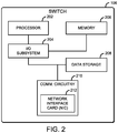
- the illustrative switch 106 includes a processor 202, an input/output (I/O) subsystem 204, a memory 206, a data storage device 208, and communication circuitry 210.
- the switch 106 may include other or additional components, such as those commonly found in a switch, in other embodiments.
- one or more of the illustrative components may be incorporated in, or otherwise form a portion of, another component.
- the memory 206, or portions thereof may be incorporated in the processor 202 in some embodiments.
- one or more of the illustrative components may be omitted from the switch 106.
- the processor 202 may be embodied as any type of processor capable of performing the functions described herein.
- the processor 202 may be embodied as a single or multi-core processor(s), digital signal processor, microcontroller, or other processor or processing/controlling circuit.
- the memory 206 may be embodied as any type of volatile or non-volatile memory or data storage capable of performing the functions described herein. In operation, the memory 206 may store various data and software used during operation of the switch 106, such as operating systems, applications, programs, libraries, and drivers.
- the memory 206 is communicatively coupled to the processor 202 via the I/O subsystem 204, which may be embodied as circuitry and/or components to facilitate input/output operations with the processor 202, the memory 206, and other components of the switch 106.
- the I/O subsystem 204 may be embodied as, or otherwise include, memory controller hubs, input/output control hubs, firmware devices, communication links (i.e., point-to-point links, bus links, wires, cables, light guides, printed circuit board traces, etc.) and/or other components and subsystems to facilitate the input/output operations.
- the I/O subsystem 204 may form a portion of a system-on-a-chip (SoC) and be incorporated, along with the processor 202, the memory 206, and other components of the switch 106, on a single integrated circuit chip.
- SoC system-on-a-chip
- the data storage device 208 may be embodied as any type of device or devices configured for short-term or long-term storage of data such as, for example, memory devices and circuits, memory cards, hard disk drives, solid-state drives, or other data storage devices. It should be appreciated that the data storage device 208 and/or the memory 206 (e.g., the computer-readable storage media) may store various data as described herein, including operating systems, applications, programs, libraries, drivers, instructions, etc., capable of being executed by a processor (e.g., the processor 202) of the switch 106.
- a processor e.g., the processor 202
- the communication circuitry 210 may be embodied as any communication circuit, device, or collection thereof, capable of enabling communications between the switch 106 and other computing devices (e.g., the source endpoint node 102, the computing nodes 110, the destination endpoint node 108, etc.) over a network (e.g., the network 104).
- the communication circuitry 210 may be configured to use any one or more communication technologies (e.g., wireless or wired communication technologies) and associated protocols (e.g., Ethernet, Bluetooth®, Wi-Fi®, WiMAX, LTE, 5G, etc.) to effect such communication.
- the illustrative communication circuitry 210 includes a network interface controller (NIC) 212.
- the NIC 212 may be embodied as one or more add-in-boards, daughtercards, network interface cards, controller chips, chipsets, or other devices that may be used by the switch 106.
- the NIC 212 may be integrated with the processor 202, embodied as an expansion card coupled to the I/O subsystem 204 over an expansion bus (e.g., PCI Express), part of an SoC that includes one or more processors, or included on a multichip package that also contains one or more processors.
- PCI Express Peripheral Component Interconnect Express
- the NIC 212 may include a local processor (not shown) and/or a local memory (not shown) that are both local to the NIC 212.
- the local processor of the NIC 212 may be capable of performing the offloaded functions (e.g., replication, network packet processing, etc.) as described herein.
- the local memory of the NIC 212 may be capable of storing data local to the NIC 212.
- functionality of the NIC 212 may be integrated into one or more components of the switch 106 at the board level, socket level, chip level, and/or other levels.
- the system may include an intermediary computing device (not shown) (e.g., a computer networking device, a client service node, a proxy computing device, etc.) that includes the components of the illustrative switch 106 of FIG. 2 , as well as a hardware switch and/or a NIC capable of performing the functions of the switch 106 as described herein.
- the switch 106 may not be a standalone computing device, but rather the switch 106 may be a hardware component of the intermediary computing device (e.g., a hardware switch, a NIC, etc.) to which the functions described herein may be offloaded to and performed by.
- the illustrative cluster of computing nodes 110 includes a first computing node, which is designated as computing node (1) 112, a second computing node, which is designated as computing node (2) 114, and a third computing node, which is designated as computing node (N) 116 (i.e., the "Nth" computing node of the computing nodes 110, wherein "N" is a positive integer and designates one or more additional computing nodes 110).
- the computing nodes 110 may be embodied as any type of computation or computer device capable of performing the functions described herein, including, without limitation, a server (e.g., stand-alone, rack-mounted, blade, etc.), a network appliance (e.g., physical or virtual), a high-performance computing device, a web appliance, a distributed computing system, a computer, a processor-based system, a multiprocessor system, and/or a mobile computing device (e.g., a smartphone, a tablet computer, a laptop computer, a notebook computer, a wearable computing device, etc.).
- a server e.g., stand-alone, rack-mounted, blade, etc.
- a network appliance e.g., physical or virtual
- a high-performance computing device e.g., a web appliance
- a distributed computing system e.g., a computer, a processor-based system, a multiprocessor system
- a mobile computing device e.g., a smartphone,
- each of the computing nodes 110 may include a processor, an I/O subsystem, a memory, a data storage device, and/or communication circuitry, which are not shown for clarity of the description. Accordingly, further descriptions of the like components are not repeated herein with the understanding that the description of the corresponding components provided above in regard to the switch 106 applies equally to the corresponding components of each of the computing nodes 110.
- Each of the source endpoint node 102 and the destination endpoint node 108 may be embodied as any type of computation or computer device capable of performing the functions described herein, including, without limitation, a compute device, a storage device, a mobile computing device (e.g., a smartphone, a tablet, a laptop, a notebook, a wearable, etc.), a server (e.g., stand-alone, rack-mounted, blade, etc.), a network appliance (e.g., physical or virtual), a web appliance, a distributed computing system, a processor-based system, and/or a multiprocessor system. Similar to the illustrative switch 106 of FIG.
- each of the source endpoint node 102 and the destination endpoint node 108 may include a processor, an I/O subsystem, a memory, a data storage device, and/or communication circuitry, which are not shown for clarity of the description. As such, further descriptions of the like components are not repeated herein with the understanding that the description of the corresponding components provided above in regard to the switch 106 applies equally to the corresponding components of the source endpoint node 102 and the destination endpoint node 108.
- the system 100 may additionally include a controller node 118 (e.g., a network controller) that is communicatively coupled to the switch 106.
- the controller node 118 may be embodied as any type of type of hardware, software, and/or firmware capable of performing the functions described herein.
- the controller node 118 may be embodied as a hypervisor or virtual machine manager (VMM), an SDN controller, or an NFV management and orchestration (MANO).
- the controller node 118 may be configured to provide policy information (e.g., network packet flow identifying information, network packet forwarding information, security information, network packet processing information, etc.) to the switch 106.
- policy information e.g., network packet flow identifying information, network packet forwarding information, security information, network packet processing information, etc.
- the controller node 118 may be connected to more than one switch 106. In such embodiments, the controller node 118 may be configured to discover and configure all of the capable connected switches to build a complete forwarding path for the service function chain across more than one switch 106.
- the switch 106 establishes an environment 300 during operation.
- the illustrative environment 300 includes a network communication module 310, a network packet analysis module 320, a policy management module 330, a service function chain management module 340, a metadata management module 350, and, in some embodiments, a controller interfacing module 360.
- Each of the modules, logic, and other components of the environment 300 may be embodied as hardware, software, firmware, or a combination thereof.
- each of the modules, logic, and other components of the environment 300 may form a portion of, or otherwise be established by, the processor 202, the communication circuitry 210 (e.g., the NIC 212), and/or other hardware components of the switch 106.
- the modules of the environment 300 may be embodied as circuitry or a collection of electrical devices (e.g., network communication circuitry 310, network packet analysis circuitry 320, policy management circuitry 330, service function chain management circuitry 340, metadata management circuitry 350, controller interfacing circuitry 360, etc.).
- the switch 106 includes service function chain data 302 and policy data 304, each of which may be accessed by the various modules and/or sub-modules of the switch 106. It should be appreciated that the switch 106 may include other components, sub-components, modules, sub-modules, and/or devices commonly found in a network switch, which are not illustrated in FIG. 3 for clarity of the description.
- the network communication module 310 is configured to facilitate inbound and outbound network communications (e.g., network traffic, network packets, network flows, etc.) to and from the switch 106. To do so, the network communication module 310 is configured to receive and process network packets from other computing devices (e.g., the source endpoint node 102, one or more of the computing nodes 110, and/or another computing device communicatively coupled via the network 104). Additionally, the network communication module 310 is configured to prepare and transmit network packets to another computing device (e.g., the destination computing node 108, one or more of the computing nodes 110, and/or another computing device communicatively coupled via the network 104). Accordingly, in some embodiments, at least a portion of the functionality of the network communication module 310 may be performed by the communication circuitry 210, and more specifically by the NIC 212.
- the network communication module 310 may be performed by the communication circuitry 210, and more specifically by the NIC 212.
- the network packet analysis module 320 is configured to analyze at least a portion of the network packet (e.g., a header of the network packet) to determine a classification (e.g., a payload type, a workload type, a service context, etc.) a network packet received by the switch 106. To do so, in some embodiments, the network packet analysis module 320 may be configured to retrieve an identifier (e.g., a source internet protocol (IP) address, a destination IP address, a source network port, a destination network port, a dynamic host configuration protocol (DHCP) address, a protocol, etc.) of the network packet, such as from a header of the network packet.
- IP internet protocol
- DHCP dynamic host configuration protocol
- an allocation scheme may be used, such as Network Service Header (NSH) Context Header Allocation.
- NSH Network Service Header
- the network packet analysis module 320 may rely on the allocation scheme (e.g., NSH structure context headers) to provide a mechanism for carrying out the classification of the network packet, determining metadata for the network packet to be processed by each of the various service functions of the service function chain, and/or providing an insertion point at which to store the metadata.
- the policy management module 330 is configured manage and enforce policies for network packets received at the switch 106. To do so, the policy management module includes a policy determination module 332 and a policy enforcement module 334.
- the policy determination module 332 is configured to determine a policy for each received network packet based a previously determined characteristic of the network packet, such as the identifier and/or the classification.
- the policy enforcement module 334 is configured to enforce the policies, such as those policies received from the controller via the controller interfacing module 360, as described below.
- Each policy defines a set of instructions usable by the policy determination module 332 and/or the policy enforcement module 334 to perform a particular function or to forward instruction to another computing device (e.g., one of the computing nodes 110) usable by the receiving computing device to perform a particular function.
- each policy may be usable to identify a corresponding network flow based on the identifier/characteristic of the network packet, as well as a set of service functions (e.g., packet inspection, intrusion detection, and firewalls) that are required to process the received network packet.
- the policy may be stored in the policy data 304.
- the service function chain management module 340 is configured to generate, or otherwise determine, the service functions of the service function chain to process the network packet.
- the service function chain management module 340 is configured to manage a service function chain of a plurality of service functions, each of which may be configured to perform a particular network packet processing function.
- the service function chain management module 340 includes a service function management module 342 and a service function interfacing module 344.
- the service function management module 342 is configured provide information to one or more of the computing nodes 110 usable by the computing nodes 110 to spin up and wind down one or more virtual machines (VMs) for each of the service functions of the service function chain. Additionally, the service function management module 342 is configured to manage which VMs have been instantiate on which of the computing nodes 110, as well as which service function is to be performed by each of the VMs. In some embodiments, such information may be stored in the service function chain data 302.
- VMs virtual machines
- the service function interfacing module 344 is configured to provide an interface between the switch 106 and each service function of the service function chain running on the one or more of the computing nodes 110. As such, the network service interfacing module 344 is configured to forward the network packet to the appropriate computing nodes 110 based on which of the computing nodes 110 is performing a particular service function. Additionally, the network service interfacing module 344 is configured to receive feedback from the computing nodes 110 as a result of the service function(s) being performed thereon. It should be appreciated that, in some embodiments, such as when the service function is non-service function chain aware or is a legacy service, a service function chain proxy may be implemented between the service function interfacing module 344 and the service function to process and/or store the metadata.
- the metadata management module 350 is configured to determine metadata that corresponds to the received network packet.
- the metadata may include information usable to identify the classification and/or the policy of the network packet, such that the metadata may be used to create and/or enforce policies.
- the metadata may include a hash result of the identifier of the network packet such that each service function in the service function chain does not have to compute the hash key.
- the metadata may include whether or not a payload of the network packet is a reconstructed IP frame, such that each service function does not have to process the TCP/IP stack and removes the latency, energy, etc. attributable to such processing.
- the metadata may include timestamp information about packet arrival in each service function.
- the metadata may include tenant specific information.
- the metadata may be based on the determined characteristic of the received network packet, a service function to which the network packet is to be forwarded, and/or feedback received from a previous service function at which the network packet was previously processed.
- the metadata may be further based on a static configuration (e.g., configured by the controller node 118) and/or a dynamic condition encountered by the previous service function of the service function chain.
- the metadata may be standardized or proprietary to particular service providers.
- the metadata management module 350 is configured to insert the metadata into a portion (e.g., a header) of the network packet.
- the metadata management module 350 may include a network packet modification module 352 to modify (e.g., insert or remove) metadata in a header of the network packet.
- the received network packet may be preserved to maintain the integrity of the network packet.
- the network packet modification module 352 may be further configured to generate a replica of the received network packet. Accordingly, it should be appreciated that modifications to the network packet, such as those described herein, may be performed on the replicated network packet rather than the received network packet.
- the metadata management module 350 may be additionally or alternatively configured to store the metadata local to the switch 106 and provide an application programming interface (API) to the corresponding service function such that the corresponding service function can use the API to read the locally stored metadata.
- the metadata management module 350 may include an application programming interface (API) module 354 to store the metadata locally (e.g., in memory 206 and/or the data storage device 208) and provide the API to the corresponding service function to read the locally stored metadata.
- API application programming interface
- the metadata management module 350 may be further configured to maintain statistics of the metadata.
- the switch 106 may use the statistics to perform load balancing, optimize paths, etc.
- the controller interfacing module 360 may be configured to interface with a controller (e.g., the controller node 118).
- the controller interfacing module 360 may be configured to receive policy information (e.g., metadata collection policy data, service function policy data, etc.) from the controller that is usable by the switch 106 to perform a particular function.
- policy information e.g., metadata collection policy data, service function policy data, etc.
- policy information may be stored at the policy data 304.
- policy information may be used to determine a characteristic of the network packet and/or define which service functions are required to process the network packet.
- the controller interfacing module 360 may additionally provide feedback to the controller, which may be usable by the controller to update the policy information for the switch 106.
- the switch 106 may execute a method 400 for switch-assisted service function chain management. It should be appreciated that at least a portion of the method 400 may be offloaded to and executed by the NIC 212 of the switch 106. It should be further appreciated that, in some embodiments, the method 400 may be embodied as various instructions stored on a computer-readable media, which may be executed by the processor 202, the NIC 212, and/or other components of the switch 106 to cause the switch 106 to perform the method 400.
- the computer-readable media may be embodied as any type of media capable of being read by the switch 106 including, but not limited to, the memory 206, the data storage 208, a local memory of the NIC 212, other memory or data storage devices of the switch 106, portable media readable by a peripheral device of the switch 106, and/or other media.
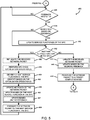
- the method 400 begins with block 402, in which the switch 106 determines whether a network packet was received by the switch 106, such as from the source endpoint node 102. If the network packet was not received, the method 400 loops back to block 402 to continue to determine whether the network packet was received. Otherwise, if the network packet was received, the method 400 advances to block 404.
- the switch 106 determines an identifier of the network packet. As described previously, the identifier may include any data indicative of an identifiable characteristic of a data object included in the network packet, such as, but not limited to a source IP address, a destination IP address, a source network port, a destination network port, a protocol, etc.
- the switch 106 may parse a header of the network packet to extract particular information from the header.
- the switch 106 determines a classification (e.g., a network flow, a workload type, an application type, etc.) of the network packet.
- the classification may be based on a comparison (e.g., a tuple-match) by the switch 106 of the identifier determined during the network packet analysis performed in block 404.
- the switch 106 may determine the classification based on the identifier determined in block 404.
- the switch 106 determines a policy of the network packet.
- the policy may include instructions providing direction to the switch 106 on particular functions to perform, how to perform the particular functions, and/or instructions to be provided to other computing devices to perform particular functions.
- the policy may be determined based on the classification determined in block 406.
- the switch 106 determines metadata of the network packet.
- the metadata may include information usable to identify the classification and/or the policy of the network packet, such that the metadata may be used to create and/or enforce policies, for example.
- the switch 106 determines the metadata based on the policy and/or the classification.
- the switch 106 creates a context (i.e., a service context) for generation of service functions of a service function chain.
- the context may be used by the switch 106 to provide instruction to one or more of the computing nodes 110 that indicates a variety of service functions to be performed at the computing nodes 110.
- the switch 106 creates the context based on the metadata determined at block 414 and/or the policy determined at block 410.
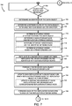
- the switch 106 may replicate the network packet to preserve the integrity of the received network packet. In other words, the replicated network packet may be modified (e.g., in block 430) and processed by the various service functions rather than the received network packet.
- the switch 106 identifies a VM presently executing at one of the computing nodes 110 capable of performing a first service function in the service function chain (i.e., generated by the context created in block 418).
- the switch 106 updates the metadata of the network packet.
- the switch 106 modifies a header of the network packet to include the metadata determined at block 414.
- the switch 106 stores the metadata local to the switch 106 (e.g., the memory 206 and/or the data storage device 208) and provides an API to the first service function such that the API is usable by the first service function to read the metadata stored local to the switch 106.
- the switch 106 forwards the network packet to the first service function of the service function chain.
- the switch 106 determines whether feedback was received for the first service function. If not, the method 400 loops back to block 436 to continue to determine whether the feedback was received. Otherwise, if the feedback was received, the method 400 advances to block 438.
- the switch 106 determines whether to modify the existing service functions of the service function chain (i.e., modify the present service function chain) based on the feedback. If the service function chain is to be modified, the method 400 advances to block 440, wherein the switch 106 updates one or more of the service functions of the service function chain before advancing to block 442 described below. Otherwise, if the switch 106 determines not to modify the service function chain, the method 400 advances to block 442.
- the switch 106 determines whether the service function chain includes another service function. If not, the method 400 branches to block 444. In some embodiments, in block 444, the switch 106 may update the network packet. For example, in some embodiments, in block 446, the switch 106 may update the network packet based on the feedback received in block 436. In block 448, the updated network packet is forwarded to a target computing node (e.g., the destination computing node 108 of FIG. 1 ) before the method 400 returns to block 402 to determine whether another network packet was received.
- a target computing node e.g., the destination computing node 108 of FIG. 1
- the method 400 branches to block 450.
- the switch 106 may again replicate the received network packet.
- the operations performed by the switch 106 in blocks 458 and 464 may be performed using the replicated network packet rather than the received network packet, thereby preserving the integrity of the received network packet.
- the switch 106 may perform a service function chain optimization operation. Such optimization operations may include a load balancing operation (e.g., based on a load balancing policy), a service availability check, etc.
- the switch 106 identifies a next service function in the service function chain. In some embodiments, in block 456, the switch 106 may identify the next service function based on one or more of the optimization operations performed at block 452. In block 458, the switch 106 updates the metadata of the network packet. In some embodiments, in block 460, the switch 106 may update the metadata based on the next service function in the service function chain identified in block 454. Additionally or alternatively, in some embodiments, in block 462, the switch 106 may update the metadata based on the feedback received at block 436. In block 464, the switch 106 forwards the network packet including the updated metadata to the next service function identified in block 454 before the method 400 loops back to block 436 to receive feedback from the next service function.
- the switch 106 may establish an environment 600 during operation, which may be established instead of or in addition to the environment 300.
- the illustrative environment 600 includes a data object storage management module 610, as well as the network communication module 310 of FIG. 3 , and, in some embodiments, the controller interfacing module 360 of FIG. 3 .
- Each of the modules, logic, and other components of the environment 600 may be embodied as hardware, software, firmware, or a combination thereof.
- each of the modules, logic, and other components of the environment 600 may form a portion of, or otherwise be established by, the processor 202, the communication circuitry 210 (e.g., the NIC 212), and/or other hardware components of the switch 106.
- the modules of the environment 600 may be embodied as circuitry or a collection of electrical devices (e.g., data object storage management circuitry 610, etc.).
- the switch 106 includes service function chain data 602 and the policy data 304 of FIG. 3 , each of which may be accessed by the various modules and/or sub-modules of the switch 106. It should be appreciated that the switch 106 may include other components, sub-components, modules, sub-modules, and/or devices commonly found in a network switch, which are not illustrated in FIG. 6 for clarity of the description.
- the network communication module 310 is configured to facilitate inbound and outbound network communications (e.g., network traffic, network packets, network flows, etc.) to and from the switch 106.
- the network communication module 310 may be configured to receive a network packet that includes a data object (e.g., a payload of a network packet) to be stored at a plurality of storage nodes (i.e., the computing nodes 110 capable of storing the data object).
- the controller interfacing module 360 may be configured to interface with a controller (e.g., the controller node 118), such as to retrieve policy information from the controller which may be stored in the policy data 304.
- the controller interfacing module 350 may be configured to receive a policy that maps a characteristic of the network packet and/or the data object (e.g., a work flow, a workload type, a payload type, etc.) to a plurality of storage nodes.
- the mapping policy may be stored at the policy data 304.
- the data object storage management module 610 is configured to receive a data object and identify and store the received data object at a plurality of the computing nodes 110. To do so, the data object storage management module 610 includes a storage node identification module 612, a data object replication module 614, a network packet modification module 616, and a computing node interfacing module 618.
- the storage node identification module 612 is configured to determine one or more storage nodes from the cluster of computing nodes 110 at which to store the data object. To do so, in some embodiments, the storage node identification module 612 may be configured to identify a network flow of the received data object, such as based on an identifier (e.g., a source IP address, a destination IP address, a source network port, a destination network port, a protocol, etc.) of the network packet and/or the data object.
- the identifier may include any data indicative of an identifiable characteristic of the data object, such as, but not limited to a source IP address, a destination IP address, a source network port, a destination network port, a protocol, etc.
- the storage node identification module 612 may receive, from the source endpoint node 102, a list that includes identifying information of each of the storage nodes on which to store the data object.
- the storage node identification module 612 may be further configured to identify a main storage node to store the received data object and one or more storage nodes to store replicas of the data object.
- the data object replication module 614 is configured to replicate the data object. To do so, the data object replication module 614 is configured to replicate the received data object a number of times equal to the number of storage nodes identified by the storage node identification module 612 on which to store the replicated data objects. Additionally, the data object replication module 614 is further configured to replicate information (e.g., header information, flow information, etc.) for each of the replicated data objects. The replicated information may be usable by the network communication module 310 to identify which of the replication storage nodes to forward a replicated data object.
- information e.g., header information, flow information, etc.
- the network packet modification module 616 is configured to modify the replicated information based on which of the replication storage nodes the replicated data object is to be forwarded to. For example, the network packet modification module 616 may be configured to update a characteristic (e.g., a destination address, a network flow, etc.) of the information corresponding to one of the replication storage nodes based on which replication storage node the replicated data object is to be forwarded to.
- a characteristic e.g., a destination address, a network flow, etc.
- the computing node interfacing module 618 is configured to forward the data object and the replicated data objects to the identified storage nodes, such as those storage nodes identified by the storage node identification module.
- the computing node interfacing module 618 is further configured to receive and track acknowledgment network packets received from the storage nodes to which the data object and the replicated data objects were forwarded. Further, the computing node interfacing module 618 is configured to forward the received acknowledgment network packets to a computing node (e.g., the source endpoint node 102) from which the data object was originally received.
- the switch 106 may execute a method 700 for switch assisted data object replication. It should be appreciated that at least a portion of the method 700 may be offloaded to and executed by the NIC 212 of the switch 106. It should be further appreciated that, in some embodiments, the method 700 may be embodied as various instructions stored on a computer-readable media, which may be executed by the processor 202, the NIC 212, and/or other components of the switch 106 to cause the switch 106 to perform the method 700.
- the computer-readable media may be embodied as any type of media capable of being read by the switch 106 including, but not limited to, the memory 206, the data storage 208, a local memory of the NIC 212, other memory or data storage devices of the switch 106, portable media readable by a peripheral device of the switch 106, and/or other media.
- the method 700 begins with block 702, in which the switch 106 determines whether a data object (i.e., encapsulated in a network packet) for replication (i.e., redundant backup) was received by the switch 106, such as from the source endpoint node 102. If the data object was not received, the method 700 loops back to block 702 to continue to determine whether the data object was received. Otherwise, if the data object was received, the method 700 advances to block 704.
- a data object i.e., encapsulated in a network packet
- replication i.e., redundant backup
- the switch 106 determines an identifier of the data object.
- the identifier may include any data indicative of an identifiable characteristic of the data object, such as, but not limited to a source IP address, a destination IP address, a source network port, a destination network port, a protocol, etc.
- the identifier may be determined from a header of the network packet that included the data object.
- the switch determines a network flow of the data object. To do so, in some embodiments, in block 708, the switch 106 determines the network flow of the data object based on the identifier determined at block 704.
- the switch 106 determines a plurality of storage nodes at which to store the object. In block 712, the switch 106 determines a main storage node and one or more replication storage nodes from the available computing nodes 110 capable of storing the data object. In some embodiments, in block 714, the switch 106 may determine the storage nodes (i.e., the main and replication storage nodes) based on the network flow identified in block 706. Additionally or alternatively, in some embodiments, in block 716, the switch may determine the storage nodes based on a predetermined list.
- the predetermined list (e.g., a list of storage nodes accompanying the data object in the network packet, a mapping table or a policy, etc.) may be received from an external source (e.g., the source endpoint node 102, the controller node 118, etc.) or be retrieved locally, such as from a table created local to the switch 106 based on a policy that includes a map of network flows to corresponding storage nodes, for example.
- an external source e.g., the source endpoint node 102, the controller node 118, etc.
- retrieved locally such as from a table created local to the switch 106 based on a policy that includes a map of network flows to corresponding storage nodes, for example.
- the switch 106 replicates the data object and corresponding network flow a total number of times. To do so, in block 720, the switch 106 replicates the data object and corresponding network flow a number of times based on the number of replication storage nodes determined in block 712. In block 722, the switch 106 forwards the received data object to the main storage node determined in block 712. In block 724, the switch 106 updates each of the replicated data objects based on which replication storage node the replicated data object is to be stored at. To do so, in some embodiments, in block 726, the switch 106 may update the destination address in a header field of the network packet encapsulating a replicated data object.
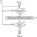
- the switch 106 forwards each of the replicated network flows and data objects to each of the replication storage nodes.
- the switch 106 determines whether an acknowledgment was received from one of the storage nodes (i.e., the main storage node or one of the replication storage nodes). If not, the method 700 loops back to block 730 to determine whether the acknowledgment was received. Otherwise, if the acknowledgment was received, the method 700 advances to block 732, wherein the switch 106 forwards the acknowledgment to the computing node (e.g., the source endpoint node 102 of FIG. 1 ) from which the data object was originally received at the switch 106. In block 734, the switch 106 determines whether there are additionally acknowledgments to be received.
- the computing node e.g., the source endpoint node 102 of FIG. 1
- the switch determines whether all of the storage nodes have returned acknowledgments to the switch 106. If not, the method 700 loops back to block 730, wherein the switch 106 determines whether another acknowledgment was received. Otherwise, if all of the storage nodes have returned an acknowledgment, the method 700 loops back to block 702, wherein the switch 106 determines whether another data object was received for replication.
Description
- Network operators and communication service providers typically rely on complex, large-scale computing environments, such as high-performance computing (HPC) and cloud computing environments. Such cloud computing environments can provide cost-effective and scalable resources that can share platform resources for applications, network services, and storage using commodity compute and storage components. However, certain support functionality, such as implementing redundant storage objects in a storage node cluster, while providing improved performance capabilities and data recovery, can introduce latencies for write operations when storing large amounts of data (i.e., resulting from the creation and maintenance of the redundant copies across multiple storage nodes of the storage node cluster). Similarly, certain operations, such as network services of a service function chain (SFC) that are typically run inside a container or virtual machine (VM) in virtualized environment, while providing scalability to match traffic demands and reduce operational costs, can introduce performance issues as loads increase the amount of processing and intelligence needed to be collected to dynamically select and apply the set of network services of the SFC.
- Patent application
US 2013/163594 A1 (D1) discloses a method for overlay-based packet steering. IETF Internet Draft draft-ietf-sfc-architecture-11 (XP015124064) (D2) discloses an architecture for the specification, creation, and ongoing maintenance of Service Function Chains in a network. Patent applicationUS 2015/003453 A1 (D3) discloses a computer-implemented method for processing network packets. - The concepts described herein are illustrated by way of example and not by way of limitation in the accompanying figures. For simplicity and clarity of illustration, elements illustrated in the figures are not necessarily drawn to scale. Where considered appropriate, reference labels have been repeated among the figures to indicate corresponding or analogous elements.
-
FIG. 1 is a simplified block diagram of at least one embodiment of a system for offloading data object replication and service function chain management that includes a set of compute nodes communicatively coupled to a switch; -
FIG. 2 is a simplified block diagram of at least one embodiment of the switch of the system ofFIG. 1 ; -
FIG. 3 is a simplified block diagram of at least one embodiment of an environment that may be established by the switch ofFIGS. 1 and2 ; -
FIGS. 4 and5 are a simplified flow diagram of at least one embodiment of a method for switch-assisted service function chain management that may be executed by the switch ofFIGS. 1 and2 ; -
FIG. 6 is a simplified block diagram of at least one other embodiment of an environment that may be established by the switch ofFIGS. 1 and2 ; and -
FIGS. 7 and8 are a simplified flow diagram of at least one embodiment of a method for switch-assisted object replication that may be executed by the switch ofFIGS. 1 and2 . - While the concepts of the present disclosure are susceptible to various modifications and alternative forms, specific embodiments thereof have been shown by way of example in the drawings and will be described herein in detail. It should be understood, however, that there is no intent to limit the concepts of the present disclosure to the particular forms disclosed, but on the contrary, the intention is to cover all modifications, equivalents, and alternatives consistent with the present disclosure and the appended claims.
- References in the specification to "one embodiment," "an embodiment," "an illustrative embodiment," etc., indicate that the embodiment described may include a particular feature, structure, or characteristic, but every embodiment may or may not necessarily include that particular feature, structure, or characteristic. Moreover, such phrases are not necessarily referring to the same embodiment. Further, when a particular feature, structure, or characteristic is described in connection with an embodiment, it is submitted that it is within the knowledge of one skilled in the art to effect such feature, structure, or characteristic in connection with other embodiments whether or not explicitly described. Additionally, it should be appreciated that items included in a list in the form of "at least one of A, B, and C" can mean (A); (B); (C): (A and B); (A and C); (B and C); or (A, B, and C). Similarly, items listed in the form of "at least one of A, B, or C" can mean (A); (B); (C): (A and B); (A and C); (B and C); or (A, B, and C).
- The disclosed embodiments may be implemented, in some cases, in hardware, firmware, software, or any combination thereof. The disclosed embodiments may also be implemented as instructions carried by or stored on one or more transitory or non-transitory machine-readable (e.g., computer-readable) storage media (e.g., memory, data storage, etc.), which may be read and executed by one or more processors. A machine-readable storage medium may be embodied as any storage device, mechanism, or other physical structure for storing or transmitting information in a form readable by a machine (e.g., a volatile or non-volatile memory, a media disc, or other media device).
- In the drawings, some structural or method features may be shown in specific arrangements and/or orderings. However, it should be appreciated that such specific arrangements and/or orderings may not be required. Rather, in some embodiments, such features may be arranged in a different manner and/or order than shown in the illustrative figures. Additionally, the inclusion of a structural or method feature in a particular figure is not meant to imply that such feature is required in all embodiments and, in some embodiments, may not be included or may be combined with other features.
- Referring now to
FIG. 1 , in an illustrative embodiment, asystem 100 for offloading data object replication and service function chain management includes a source endpoint node 102 and a destination endpoint node 108 communicatively coupled over a network 104 through aswitch 106. As shown, theswitch 106 is further communicatively coupled to a cluster of computing nodes 110 (e.g., compute and/or storage nodes) capable of storing objects (e.g., redundant backups) and/or performing one or more network packet processing functions (i.e., network services). - In use, the source endpoint node 102 transmits a network packet (i.e., via the network 104) that is intended to be received by a target computing node (e.g., one or more of the
computing nodes 110, the destination endpoint node 108, etc.). For example, the network packet may include a data object to be replicated and stored at one or more of thecomputing nodes 110. Accordingly, theswitch 106 can receive the data object, replicate the data object, and transmit the replicated data objects to a subset of the identifiedcomputing nodes 110 on which the replicated objects are to be stored. - However, unlike conventional technologies (i.e., switches without hardware offload support for flow/object replication), wherein the replication and forwarding of the data object is performed at each of the
computing nodes 110 identified to store the data object, theswitch 106 is configured to support hardware offload for flow/object replication. As such, theswitch 106 can perform the data object replication and update a portion (e.g., a header) of the network packet for each of the identifiedcomputing nodes 110. In other words, the work (e.g., establishing connections between the computing nodes on which to store the data object, replicating the data object, transferring the data object between the computing nodes, etc.) can be offloaded to theswitch 106, thereby removing the latency and overhead associated with the conventional technologies. - In another example, the network packet may be received by the
switch 106 and require processing of the network packet to be performed prior to being transmitted to a target computing node (e.g., the destination endpoint node 108). To do so, virtualized service functions (i.e., network services, network functions, etc.), such as firewall services, network address translation (NAT) services, load-balancing services, deep packet inspection (DPI) services, intrusion detection and/or prevention system (IDS/IPS) services, encapsulation services, transmission control protocol (TCP) optimization services, encryption/decryption services, and/or other processing services, can be dynamically chained together to form a service function chain in a process referred to as service chaining. In a service function chain, each service function is performed by one or more virtual machines (VMs), which are typically spun on one or more of thecomputing nodes 110 to perform a particular service function of the service function chain. - An example service function chain includes more than one security service function (e.g., a virtualized firewall function, a virtualized intrusion detection function, etc.), each of which may be configured to process, in a particular order, the network packet. However, unlike traditional service function chain technologies, wherein each service function in the service function chain extracts and computes metadata of the network packet, as well as manipulating a header of the network packet, and forwards the network packet to the next service function in the service function chain, the
switch 106 is configured to support hardware offload for service function metadata extraction/computation and network packet manipulation and forwarding. In other words, the work (e.g., computations performed at each network service of the service function chain) can be offloaded to theswitch 106, thereby removing the overhead and latency attributable to the computations performed at each network service of the service function chain. - The network 104 may be embodied as any type of wired or wireless communication network, including cellular networks, such as Global System for Mobile Communications (GSM) or Long-Term Evolution (LTE), telephony networks, digital subscriber line (DSL) networks, cable networks, local or wide area networks, global networks (e.g., the Internet), or any combination thereof. It should be appreciated that the network 104 may serve as a centralized network and, in some embodiments, may be communicatively coupled to another network (e.g., the Internet). Accordingly, the network 104 may include a variety of network devices (not shown), virtual and physical, such as routers, switches, network hubs, servers, storage devices, compute devices, etc., as needed to facilitate communication between the source endpoint node 102 and the
switch 106, as well as theswitch 106 and the destination endpoint node 108. - The
switch 106 may be embodied as any type of network packet switching device that is capable of forwarding data (e.g., network packets) between computing devices (e.g., the source endpoint node 102 and thecomputing nodes 110, the source endpoint node 102 and the destination computing node 108, etc.) and performing the functions described herein. For example, theswitch 106 may be embodied as, without limitation, a rack-mounted switch, a standalone switch, a fully managed switch, a partially managed switch, a full-duplex and/or half-duplex communication mode enabled switch, etc. As shown inFIG. 2 , theillustrative switch 106 includes aprocessor 202, an input/output (I/O)subsystem 204, amemory 206, adata storage device 208, andcommunication circuitry 210. Of course, theswitch 106 may include other or additional components, such as those commonly found in a switch, in other embodiments. Additionally, in some embodiments, one or more of the illustrative components may be incorporated in, or otherwise form a portion of, another component. For example, thememory 206, or portions thereof, may be incorporated in theprocessor 202 in some embodiments. Further, in some embodiments, one or more of the illustrative components may be omitted from theswitch 106. - The
processor 202 may be embodied as any type of processor capable of performing the functions described herein. For example, theprocessor 202 may be embodied as a single or multi-core processor(s), digital signal processor, microcontroller, or other processor or processing/controlling circuit. Similarly, thememory 206 may be embodied as any type of volatile or non-volatile memory or data storage capable of performing the functions described herein. In operation, thememory 206 may store various data and software used during operation of theswitch 106, such as operating systems, applications, programs, libraries, and drivers. Thememory 206 is communicatively coupled to theprocessor 202 via the I/O subsystem 204, which may be embodied as circuitry and/or components to facilitate input/output operations with theprocessor 202, thememory 206, and other components of theswitch 106. For example, the I/O subsystem 204 may be embodied as, or otherwise include, memory controller hubs, input/output control hubs, firmware devices, communication links (i.e., point-to-point links, bus links, wires, cables, light guides, printed circuit board traces, etc.) and/or other components and subsystems to facilitate the input/output operations. In some embodiments, the I/O subsystem 204 may form a portion of a system-on-a-chip (SoC) and be incorporated, along with theprocessor 202, thememory 206, and other components of theswitch 106, on a single integrated circuit chip. - The
data storage device 208 may be embodied as any type of device or devices configured for short-term or long-term storage of data such as, for example, memory devices and circuits, memory cards, hard disk drives, solid-state drives, or other data storage devices. It should be appreciated that thedata storage device 208 and/or the memory 206 (e.g., the computer-readable storage media) may store various data as described herein, including operating systems, applications, programs, libraries, drivers, instructions, etc., capable of being executed by a processor (e.g., the processor 202) of theswitch 106. - The
communication circuitry 210 may be embodied as any communication circuit, device, or collection thereof, capable of enabling communications between theswitch 106 and other computing devices (e.g., the source endpoint node 102, thecomputing nodes 110, the destination endpoint node 108, etc.) over a network (e.g., the network 104). Thecommunication circuitry 210 may be configured to use any one or more communication technologies (e.g., wireless or wired communication technologies) and associated protocols (e.g., Ethernet, Bluetooth®, Wi-Fi®, WiMAX, LTE, 5G, etc.) to effect such communication. - The
illustrative communication circuitry 210 includes a network interface controller (NIC) 212. TheNIC 212 may be embodied as one or more add-in-boards, daughtercards, network interface cards, controller chips, chipsets, or other devices that may be used by theswitch 106. For example, in some embodiments, theNIC 212 may be integrated with theprocessor 202, embodied as an expansion card coupled to the I/O subsystem 204 over an expansion bus (e.g., PCI Express), part of an SoC that includes one or more processors, or included on a multichip package that also contains one or more processors. - Alternatively, in some embodiments, the
NIC 212 may include a local processor (not shown) and/or a local memory (not shown) that are both local to theNIC 212. In such embodiments, the local processor of theNIC 212 may be capable of performing the offloaded functions (e.g., replication, network packet processing, etc.) as described herein. Additionally or alternatively, in such embodiments, the local memory of theNIC 212 may be capable of storing data local to theNIC 212. Additionally or alternatively, in some embodiments, functionality of theNIC 212 may be integrated into one or more components of theswitch 106 at the board level, socket level, chip level, and/or other levels. - It should be appreciated that, in some embodiments, the system may include an intermediary computing device (not shown) (e.g., a computer networking device, a client service node, a proxy computing device, etc.) that includes the components of the
illustrative switch 106 ofFIG. 2 , as well as a hardware switch and/or a NIC capable of performing the functions of theswitch 106 as described herein. In other words, in some embodiments, theswitch 106 may not be a standalone computing device, but rather theswitch 106 may be a hardware component of the intermediary computing device (e.g., a hardware switch, a NIC, etc.) to which the functions described herein may be offloaded to and performed by. - Referring again to
FIG. 1 , the illustrative cluster ofcomputing nodes 110 includes a first computing node, which is designated as computing node (1) 112, a second computing node, which is designated as computing node (2) 114, and a third computing node, which is designated as computing node (N) 116 (i.e., the "Nth" computing node of thecomputing nodes 110, wherein "N" is a positive integer and designates one or more additional computing nodes 110). Thecomputing nodes 110 may be embodied as any type of computation or computer device capable of performing the functions described herein, including, without limitation, a server (e.g., stand-alone, rack-mounted, blade, etc.), a network appliance (e.g., physical or virtual), a high-performance computing device, a web appliance, a distributed computing system, a computer, a processor-based system, a multiprocessor system, and/or a mobile computing device (e.g., a smartphone, a tablet computer, a laptop computer, a notebook computer, a wearable computing device, etc.). As such, similar to theillustrative switch 106 ofFIG. 2 , each of thecomputing nodes 110 may include a processor, an I/O subsystem, a memory, a data storage device, and/or communication circuitry, which are not shown for clarity of the description. Accordingly, further descriptions of the like components are not repeated herein with the understanding that the description of the corresponding components provided above in regard to theswitch 106 applies equally to the corresponding components of each of thecomputing nodes 110. - Each of the source endpoint node 102 and the destination endpoint node 108 may be embodied as any type of computation or computer device capable of performing the functions described herein, including, without limitation, a compute device, a storage device, a mobile computing device (e.g., a smartphone, a tablet, a laptop, a notebook, a wearable, etc.), a server (e.g., stand-alone, rack-mounted, blade, etc.), a network appliance (e.g., physical or virtual), a web appliance, a distributed computing system, a processor-based system, and/or a multiprocessor system. Similar to the
illustrative switch 106 ofFIG. 2 , each of the source endpoint node 102 and the destination endpoint node 108 may include a processor, an I/O subsystem, a memory, a data storage device, and/or communication circuitry, which are not shown for clarity of the description. As such, further descriptions of the like components are not repeated herein with the understanding that the description of the corresponding components provided above in regard to theswitch 106 applies equally to the corresponding components of the source endpoint node 102 and the destination endpoint node 108. - In some embodiments, the
system 100 may additionally include a controller node 118 (e.g., a network controller) that is communicatively coupled to theswitch 106. Thecontroller node 118 may be embodied as any type of type of hardware, software, and/or firmware capable of performing the functions described herein. For example, in some embodiments, without limitation, thecontroller node 118 may be embodied as a hypervisor or virtual machine manager (VMM), an SDN controller, or an NFV management and orchestration (MANO). In such embodiments, thecontroller node 118 may be configured to provide policy information (e.g., network packet flow identifying information, network packet forwarding information, security information, network packet processing information, etc.) to theswitch 106. It should be appreciated that, in some embodiments, thecontroller node 118 may be connected to more than oneswitch 106. In such embodiments, thecontroller node 118 may be configured to discover and configure all of the capable connected switches to build a complete forwarding path for the service function chain across more than oneswitch 106. - Referring now to
FIG. 3 , in an illustrative embodiment, theswitch 106 establishes anenvironment 300 during operation. Theillustrative environment 300 includes anetwork communication module 310, a networkpacket analysis module 320, apolicy management module 330, a service functionchain management module 340, ametadata management module 350, and, in some embodiments, acontroller interfacing module 360. Each of the modules, logic, and other components of theenvironment 300 may be embodied as hardware, software, firmware, or a combination thereof. For example, each of the modules, logic, and other components of theenvironment 300 may form a portion of, or otherwise be established by, theprocessor 202, the communication circuitry 210 (e.g., the NIC 212), and/or other hardware components of theswitch 106. As such, in some embodiments, one or more of the modules of theenvironment 300 may be embodied as circuitry or a collection of electrical devices (e.g.,network communication circuitry 310, networkpacket analysis circuitry 320,policy management circuitry 330, service functionchain management circuitry 340,metadata management circuitry 350,controller interfacing circuitry 360, etc.). - In the
illustrative environment 300, theswitch 106 includes servicefunction chain data 302 andpolicy data 304, each of which may be accessed by the various modules and/or sub-modules of theswitch 106. It should be appreciated that theswitch 106 may include other components, sub-components, modules, sub-modules, and/or devices commonly found in a network switch, which are not illustrated inFIG. 3 for clarity of the description. - The
network communication module 310 is configured to facilitate inbound and outbound network communications (e.g., network traffic, network packets, network flows, etc.) to and from theswitch 106. To do so, thenetwork communication module 310 is configured to receive and process network packets from other computing devices (e.g., the source endpoint node 102, one or more of thecomputing nodes 110, and/or another computing device communicatively coupled via the network 104). Additionally, thenetwork communication module 310 is configured to prepare and transmit network packets to another computing device (e.g., the destination computing node 108, one or more of thecomputing nodes 110, and/or another computing device communicatively coupled via the network 104). Accordingly, in some embodiments, at least a portion of the functionality of thenetwork communication module 310 may be performed by thecommunication circuitry 210, and more specifically by theNIC 212. - The network
packet analysis module 320 is configured to analyze at least a portion of the network packet (e.g., a header of the network packet) to determine a classification (e.g., a payload type, a workload type, a service context, etc.) a network packet received by theswitch 106. To do so, in some embodiments, the networkpacket analysis module 320 may be configured to retrieve an identifier (e.g., a source internet protocol (IP) address, a destination IP address, a source network port, a destination network port, a dynamic host configuration protocol (DHCP) address, a protocol, etc.) of the network packet, such as from a header of the network packet. For example, in some data center environments employing service function chaining, an allocation scheme may be used, such as Network Service Header (NSH) Context Header Allocation. In such embodiments, the networkpacket analysis module 320 may rely on the allocation scheme (e.g., NSH structure context headers) to provide a mechanism for carrying out the classification of the network packet, determining metadata for the network packet to be processed by each of the various service functions of the service function chain, and/or providing an insertion point at which to store the metadata. - The
policy management module 330 is configured manage and enforce policies for network packets received at theswitch 106. To do so, the policy management module includes apolicy determination module 332 and apolicy enforcement module 334. Thepolicy determination module 332 is configured to determine a policy for each received network packet based a previously determined characteristic of the network packet, such as the identifier and/or the classification. Thepolicy enforcement module 334 is configured to enforce the policies, such as those policies received from the controller via thecontroller interfacing module 360, as described below. - Each policy defines a set of instructions usable by the
policy determination module 332 and/or thepolicy enforcement module 334 to perform a particular function or to forward instruction to another computing device (e.g., one of the computing nodes 110) usable by the receiving computing device to perform a particular function. For example, each policy may be usable to identify a corresponding network flow based on the identifier/characteristic of the network packet, as well as a set of service functions (e.g., packet inspection, intrusion detection, and firewalls) that are required to process the received network packet. In some embodiments, the policy may be stored in thepolicy data 304. - The service function
chain management module 340 is configured to generate, or otherwise determine, the service functions of the service function chain to process the network packet. In other words, the service functionchain management module 340 is configured to manage a service function chain of a plurality of service functions, each of which may be configured to perform a particular network packet processing function. To do so, the service functionchain management module 340 includes a servicefunction management module 342 and a servicefunction interfacing module 344. - The service
function management module 342 is configured provide information to one or more of thecomputing nodes 110 usable by thecomputing nodes 110 to spin up and wind down one or more virtual machines (VMs) for each of the service functions of the service function chain. Additionally, the servicefunction management module 342 is configured to manage which VMs have been instantiate on which of thecomputing nodes 110, as well as which service function is to be performed by each of the VMs. In some embodiments, such information may be stored in the servicefunction chain data 302. - The service
function interfacing module 344 is configured to provide an interface between theswitch 106 and each service function of the service function chain running on the one or more of thecomputing nodes 110. As such, the networkservice interfacing module 344 is configured to forward the network packet to theappropriate computing nodes 110 based on which of thecomputing nodes 110 is performing a particular service function. Additionally, the networkservice interfacing module 344 is configured to receive feedback from thecomputing nodes 110 as a result of the service function(s) being performed thereon. It should be appreciated that, in some embodiments, such as when the service function is non-service function chain aware or is a legacy service, a service function chain proxy may be implemented between the servicefunction interfacing module 344 and the service function to process and/or store the metadata. - The
metadata management module 350 is configured to determine metadata that corresponds to the received network packet. The metadata may include information usable to identify the classification and/or the policy of the network packet, such that the metadata may be used to create and/or enforce policies. For example, the metadata may include a hash result of the identifier of the network packet such that each service function in the service function chain does not have to compute the hash key. In another example, the metadata may include whether or not a payload of the network packet is a reconstructed IP frame, such that each service function does not have to process the TCP/IP stack and removes the latency, energy, etc. attributable to such processing. In still another example, the metadata may include timestamp information about packet arrival in each service function. In yet another example, the metadata may include tenant specific information. - As such, the metadata may be based on the determined characteristic of the received network packet, a service function to which the network packet is to be forwarded, and/or feedback received from a previous service function at which the network packet was previously processed. In some embodiments, the metadata may be further based on a static configuration (e.g., configured by the controller node 118) and/or a dynamic condition encountered by the previous service function of the service function chain. Additionally, in some embodiment, the metadata may be standardized or proprietary to particular service providers.
- Additionally, the
metadata management module 350 is configured to insert the metadata into a portion (e.g., a header) of the network packet. To do so, themetadata management module 350 may include a networkpacket modification module 352 to modify (e.g., insert or remove) metadata in a header of the network packet. In some embodiments, the received network packet may be preserved to maintain the integrity of the network packet. In such embodiments, the networkpacket modification module 352 may be further configured to generate a replica of the received network packet. Accordingly, it should be appreciated that modifications to the network packet, such as those described herein, may be performed on the replicated network packet rather than the received network packet. - The
metadata management module 350 may be additionally or alternatively configured to store the metadata local to theswitch 106 and provide an application programming interface (API) to the corresponding service function such that the corresponding service function can use the API to read the locally stored metadata. To do so, themetadata management module 350 may include an application programming interface (API)module 354 to store the metadata locally (e.g., inmemory 206 and/or the data storage device 208) and provide the API to the corresponding service function to read the locally stored metadata. - In some embodiments, the
metadata management module 350 may be further configured to maintain statistics of the metadata. In such embodiments, theswitch 106 may use the statistics to perform load balancing, optimize paths, etc. - The
controller interfacing module 360 may be configured to interface with a controller (e.g., the controller node 118). For example, thecontroller interfacing module 360 may be configured to receive policy information (e.g., metadata collection policy data, service function policy data, etc.) from the controller that is usable by theswitch 106 to perform a particular function. As described previously, such policy information may be stored at thepolicy data 304. As also described previously, such policy information may be used to determine a characteristic of the network packet and/or define which service functions are required to process the network packet. In some embodiments, thecontroller interfacing module 360 may additionally provide feedback to the controller, which may be usable by the controller to update the policy information for theswitch 106. - Referring now to
FIGS. 4 and5 , in use, theswitch 106 may execute amethod 400 for switch-assisted service function chain management. It should be appreciated that at least a portion of themethod 400 may be offloaded to and executed by theNIC 212 of theswitch 106. It should be further appreciated that, in some embodiments, themethod 400 may be embodied as various instructions stored on a computer-readable media, which may be executed by theprocessor 202, theNIC 212, and/or other components of theswitch 106 to cause theswitch 106 to perform themethod 400. The computer-readable media may be embodied as any type of media capable of being read by theswitch 106 including, but not limited to, thememory 206, thedata storage 208, a local memory of theNIC 212, other memory or data storage devices of theswitch 106, portable media readable by a peripheral device of theswitch 106, and/or other media. - The
method 400 begins withblock 402, in which theswitch 106 determines whether a network packet was received by theswitch 106, such as from the source endpoint node 102. If the network packet was not received, themethod 400 loops back to block 402 to continue to determine whether the network packet was received. Otherwise, if the network packet was received, themethod 400 advances to block 404. Inblock 404, theswitch 106 determines an identifier of the network packet. As described previously, the identifier may include any data indicative of an identifiable characteristic of a data object included in the network packet, such as, but not limited to a source IP address, a destination IP address, a source network port, a destination network port, a protocol, etc. To do so, for example, theswitch 106 may parse a header of the network packet to extract particular information from the header. Inblock 406, theswitch 106 determines a classification (e.g., a network flow, a workload type, an application type, etc.) of the network packet. The classification may be based on a comparison (e.g., a tuple-match) by theswitch 106 of the identifier determined during the network packet analysis performed inblock 404. Accordingly, in some embodiments, inblock 408, theswitch 106 may determine the classification based on the identifier determined inblock 404. - In
block 410, theswitch 106 determines a policy of the network packet. As described previously, the policy may include instructions providing direction to theswitch 106 on particular functions to perform, how to perform the particular functions, and/or instructions to be provided to other computing devices to perform particular functions. In some embodiments, inblock 412, the policy may be determined based on the classification determined inblock 406. Inblock 414, theswitch 106 determines metadata of the network packet. As described previously, the metadata may include information usable to identify the classification and/or the policy of the network packet, such that the metadata may be used to create and/or enforce policies, for example. In some embodiments, inblock 416, theswitch 106 determines the metadata based on the policy and/or the classification. - In
block 418, theswitch 106 creates a context (i.e., a service context) for generation of service functions of a service function chain. In some embodiments, inblock 420, the context may be used by theswitch 106 to provide instruction to one or more of thecomputing nodes 110 that indicates a variety of service functions to be performed at thecomputing nodes 110. Additionally, in some embodiments, inblock 422, theswitch 106 creates the context based on the metadata determined atblock 414 and/or the policy determined atblock 410. - In some embodiments, in
block 424, theswitch 106 may replicate the network packet to preserve the integrity of the received network packet. In other words, the replicated network packet may be modified (e.g., in block 430) and processed by the various service functions rather than the received network packet. Inblock 426, theswitch 106 identifies a VM presently executing at one of thecomputing nodes 110 capable of performing a first service function in the service function chain (i.e., generated by the context created in block 418). Inblock 428, theswitch 106 updates the metadata of the network packet. In some embodiments, inblock 430, theswitch 106 modifies a header of the network packet to include the metadata determined atblock 414. Alternatively, in some embodiments, inblock 432, theswitch 106 stores the metadata local to the switch 106 (e.g., thememory 206 and/or the data storage device 208) and provides an API to the first service function such that the API is usable by the first service function to read the metadata stored local to theswitch 106. - In
block 434, theswitch 106 forwards the network packet to the first service function of the service function chain. Inblock 436, theswitch 106 determines whether feedback was received for the first service function. If not, themethod 400 loops back to block 436 to continue to determine whether the feedback was received. Otherwise, if the feedback was received, themethod 400 advances to block 438. Inblock 438, theswitch 106 determines whether to modify the existing service functions of the service function chain (i.e., modify the present service function chain) based on the feedback. If the service function chain is to be modified, themethod 400 advances to block 440, wherein theswitch 106 updates one or more of the service functions of the service function chain before advancing to block 442 described below. Otherwise, if theswitch 106 determines not to modify the service function chain, themethod 400 advances to block 442. - In
block 442, theswitch 106 determines whether the service function chain includes another service function. If not, themethod 400 branches to block 444. In some embodiments, inblock 444, theswitch 106 may update the network packet. For example, in some embodiments, inblock 446, theswitch 106 may update the network packet based on the feedback received inblock 436. Inblock 448, the updated network packet is forwarded to a target computing node (e.g., the destination computing node 108 ofFIG. 1 ) before themethod 400 returns to block 402 to determine whether another network packet was received. - Otherwise, if at
block 442 theswitch 106 determines the service chain includes another service function, themethod 400 branches to block 450. In some embodiments, inblock 450, theswitch 106 may again replicate the received network packet. In such embodiments, the operations performed by theswitch 106 inblocks block 452, theswitch 106 may perform a service function chain optimization operation. Such optimization operations may include a load balancing operation (e.g., based on a load balancing policy), a service availability check, etc. - In
block 454, theswitch 106 identifies a next service function in the service function chain. In some embodiments, inblock 456, theswitch 106 may identify the next service function based on one or more of the optimization operations performed atblock 452. Inblock 458, theswitch 106 updates the metadata of the network packet. In some embodiments, inblock 460, theswitch 106 may update the metadata based on the next service function in the service function chain identified inblock 454. Additionally or alternatively, in some embodiments, inblock 462, theswitch 106 may update the metadata based on the feedback received atblock 436. Inblock 464, theswitch 106 forwards the network packet including the updated metadata to the next service function identified inblock 454 before themethod 400 loops back to block 436 to receive feedback from the next service function. - Referring now to
FIG. 6 , in another illustrative embodiment, theswitch 106 may establish anenvironment 600 during operation, which may be established instead of or in addition to theenvironment 300. Theillustrative environment 600 includes a data objectstorage management module 610, as well as thenetwork communication module 310 ofFIG. 3 , and, in some embodiments, thecontroller interfacing module 360 ofFIG. 3 . Each of the modules, logic, and other components of theenvironment 600 may be embodied as hardware, software, firmware, or a combination thereof. For example, each of the modules, logic, and other components of theenvironment 600 may form a portion of, or otherwise be established by, theprocessor 202, the communication circuitry 210 (e.g., the NIC 212), and/or other hardware components of theswitch 106. As such, in some embodiments, one or more of the modules of theenvironment 600 may be embodied as circuitry or a collection of electrical devices (e.g., data objectstorage management circuitry 610, etc.). - In the
illustrative environment 600, theswitch 106 includes servicefunction chain data 602 and thepolicy data 304 ofFIG. 3 , each of which may be accessed by the various modules and/or sub-modules of theswitch 106. It should be appreciated that theswitch 106 may include other components, sub-components, modules, sub-modules, and/or devices commonly found in a network switch, which are not illustrated inFIG. 6 for clarity of the description. - As described previously, the
network communication module 310 is configured to facilitate inbound and outbound network communications (e.g., network traffic, network packets, network flows, etc.) to and from theswitch 106. In some embodiments, thenetwork communication module 310 may be configured to receive a network packet that includes a data object (e.g., a payload of a network packet) to be stored at a plurality of storage nodes (i.e., thecomputing nodes 110 capable of storing the data object). As also described previously, thecontroller interfacing module 360 may be configured to interface with a controller (e.g., the controller node 118), such as to retrieve policy information from the controller which may be stored in thepolicy data 304. In some embodiments, thecontroller interfacing module 350 may be configured to receive a policy that maps a characteristic of the network packet and/or the data object (e.g., a work flow, a workload type, a payload type, etc.) to a plurality of storage nodes. In such embodiments, the mapping policy may be stored at thepolicy data 304. - The data object
storage management module 610 is configured to receive a data object and identify and store the received data object at a plurality of thecomputing nodes 110. To do so, the data objectstorage management module 610 includes a storagenode identification module 612, a dataobject replication module 614, a networkpacket modification module 616, and a computingnode interfacing module 618. - The storage
node identification module 612 is configured to determine one or more storage nodes from the cluster ofcomputing nodes 110 at which to store the data object. To do so, in some embodiments, the storagenode identification module 612 may be configured to identify a network flow of the received data object, such as based on an identifier (e.g., a source IP address, a destination IP address, a source network port, a destination network port, a protocol, etc.) of the network packet and/or the data object. The identifier may include any data indicative of an identifiable characteristic of the data object, such as, but not limited to a source IP address, a destination IP address, a source network port, a destination network port, a protocol, etc. Alternatively, in some embodiments, the storagenode identification module 612 may receive, from the source endpoint node 102, a list that includes identifying information of each of the storage nodes on which to store the data object. The storagenode identification module 612 may be further configured to identify a main storage node to store the received data object and one or more storage nodes to store replicas of the data object. - The data object
replication module 614 is configured to replicate the data object. To do so, the data objectreplication module 614 is configured to replicate the received data object a number of times equal to the number of storage nodes identified by the storagenode identification module 612 on which to store the replicated data objects. Additionally, the data objectreplication module 614 is further configured to replicate information (e.g., header information, flow information, etc.) for each of the replicated data objects. The replicated information may be usable by thenetwork communication module 310 to identify which of the replication storage nodes to forward a replicated data object. - The network
packet modification module 616 is configured to modify the replicated information based on which of the replication storage nodes the replicated data object is to be forwarded to. For example, the networkpacket modification module 616 may be configured to update a characteristic (e.g., a destination address, a network flow, etc.) of the information corresponding to one of the replication storage nodes based on which replication storage node the replicated data object is to be forwarded to. - The computing
node interfacing module 618 is configured to forward the data object and the replicated data objects to the identified storage nodes, such as those storage nodes identified by the storage node identification module. The computingnode interfacing module 618 is further configured to receive and track acknowledgment network packets received from the storage nodes to which the data object and the replicated data objects were forwarded. Further, the computingnode interfacing module 618 is configured to forward the received acknowledgment network packets to a computing node (e.g., the source endpoint node 102) from which the data object was originally received. - Referring now to
FIGS. 7 and8 , in use, theswitch 106 may execute amethod 700 for switch assisted data object replication. It should be appreciated that at least a portion of themethod 700 may be offloaded to and executed by theNIC 212 of theswitch 106. It should be further appreciated that, in some embodiments, themethod 700 may be embodied as various instructions stored on a computer-readable media, which may be executed by theprocessor 202, theNIC 212, and/or other components of theswitch 106 to cause theswitch 106 to perform themethod 700. The computer-readable media may be embodied as any type of media capable of being read by theswitch 106 including, but not limited to, thememory 206, thedata storage 208, a local memory of theNIC 212, other memory or data storage devices of theswitch 106, portable media readable by a peripheral device of theswitch 106, and/or other media. - The
method 700 begins withblock 702, in which theswitch 106 determines whether a data object (i.e., encapsulated in a network packet) for replication (i.e., redundant backup) was received by theswitch 106, such as from the source endpoint node 102. If the data object was not received, themethod 700 loops back to block 702 to continue to determine whether the data object was received. Otherwise, if the data object was received, themethod 700 advances to block 704. - In
block 704, theswitch 106 determines an identifier of the data object. As described previously, the identifier may include any data indicative of an identifiable characteristic of the data object, such as, but not limited to a source IP address, a destination IP address, a source network port, a destination network port, a protocol, etc. For example, in some embodiments, the identifier may be determined from a header of the network packet that included the data object. Inblock 706, the switch determines a network flow of the data object. To do so, in some embodiments, inblock 708, theswitch 106 determines the network flow of the data object based on the identifier determined atblock 704. - In
block 710, theswitch 106 determines a plurality of storage nodes at which to store the object. Inblock 712, theswitch 106 determines a main storage node and one or more replication storage nodes from the available computingnodes 110 capable of storing the data object. In some embodiments, inblock 714, theswitch 106 may determine the storage nodes (i.e., the main and replication storage nodes) based on the network flow identified inblock 706. Additionally or alternatively, in some embodiments, inblock 716, the switch may determine the storage nodes based on a predetermined list. In some embodiments, the predetermined list (e.g., a list of storage nodes accompanying the data object in the network packet, a mapping table or a policy, etc.) may be received from an external source (e.g., the source endpoint node 102, thecontroller node 118, etc.) or be retrieved locally, such as from a table created local to theswitch 106 based on a policy that includes a map of network flows to corresponding storage nodes, for example. - In
block 718, theswitch 106 replicates the data object and corresponding network flow a total number of times. To do so, inblock 720, theswitch 106 replicates the data object and corresponding network flow a number of times based on the number of replication storage nodes determined inblock 712. Inblock 722, theswitch 106 forwards the received data object to the main storage node determined inblock 712. Inblock 724, theswitch 106 updates each of the replicated data objects based on which replication storage node the replicated data object is to be stored at. To do so, in some embodiments, inblock 726, theswitch 106 may update the destination address in a header field of the network packet encapsulating a replicated data object. - In
block 728, theswitch 106 forwards each of the replicated network flows and data objects to each of the replication storage nodes. Inblock 730, theswitch 106 determines whether an acknowledgment was received from one of the storage nodes (i.e., the main storage node or one of the replication storage nodes). If not, themethod 700 loops back to block 730 to determine whether the acknowledgment was received. Otherwise, if the acknowledgment was received, themethod 700 advances to block 732, wherein theswitch 106 forwards the acknowledgment to the computing node (e.g., the source endpoint node 102 ofFIG. 1 ) from which the data object was originally received at theswitch 106. Inblock 734, theswitch 106 determines whether there are additionally acknowledgments to be received. In other words, the switch determines whether all of the storage nodes have returned acknowledgments to theswitch 106. If not, themethod 700 loops back to block 730, wherein theswitch 106 determines whether another acknowledgment was received. Otherwise, if all of the storage nodes have returned an acknowledgment, themethod 700 loops back to block 702, wherein theswitch 106 determines whether another data object was received for replication.
Claims (14)
- A switch (106) for offloading service function chain management, the switch comprising:one or more processors (202); andone or more memory devices (206) having stored therein a plurality of instructions that, when executed by the one or more processors, cause the switch to:receive (402) a network packet from a source endpoint node communicatively coupled to the switch;update (428) metadata for the network packet, wherein the metadata is based on one or more of a plurality of service functions of a service function chain, the one or more of the plurality of the service functions being executed at a computing node communicatively coupled to the switch and configured to process the network packet based on the metadata;forward (434), subsequent to having inserted the metadata into the network packet, the network packet to a first service function of the plurality of service functions;receive (436), subsequent to having forwarded the network packet to the service function, feedback from the service function, wherein the feedback identifies a result of processing of the received network packet by the first service function;replicate the network packet;update (458), subsequent to having received the feedback, the metadata of the replicated network packet based on the feedback received from the first service function and a next service function of the service function chain; andforward (464), subsequent to updating the metadata of the replicated network packet, the updated network packet to a next service function of the service function chain,characterized in that the plurality of instructions further cause the switch to update (440), in response to having received the feedback from the first service function, one or more of the service functions based on the feedback received from the first service function
- The switch of claim 1, wherein the plurality of instructions further cause the switch to:determine the plurality of service functions of the service function chain for the received network packet; andprovide an indication to one or more computing nodes communicatively coupled to the switch, wherein the indication identifies a set of instructions usable by the one or more computing nodes to spin up and configure one or more virtual machines to execute at least a portion of the service functions of the service function chain.
- The switch of claim 2, wherein the plurality of instructions further cause the switch to:determine (404) an identifier of the network packet; andidentify (410) a policy corresponding to the identifier,wherein the set of instructions is usable by the one or more computing nodes to spin up and configure the one or more virtual machines to execute at least a portion of the service functions of the service function chain based on the identified policy.
- The switch of claim 1, wherein the plurality of instructions further cause the switch to prior to the update (428) of metadata for the network packet, generate (424) a replicated network packet from the network packet, wherein to insert the metadata into the network packet comprises to insert the metadata into the replicated network packet.
- The switch of claim 1, wherein the plurality of instructions further cause the switch to:determine (442), subsequent to having received the feedback, whether another service function of the service function chain is available; andforward (448), in response to a determination that the next service function chain is unavailable, the network packet to a destination computing node communicatively coupled to the switch.
- The switch of claim 1, wherein to update the metadata comprises to at least one of (i) insert (430) the metadata into a header of the network packet to include the metadata and (ii) store (432) the metadata at a storage device of the switch and to provide an application programming interface to the next service function of the service function chain, wherein the application programming interface is usable to read the metadata stored at the switch.
- The switch of claim 1, wherein the plurality of instructions further cause the switch to:determine (404) an identifier of the network packet; andidentify (410) a policy corresponding to the identifier.
- The switch of claim 7, wherein to update the metadata of the network packet comprises to (i) determine (416) the metadata based on the identified policy and (ii) insert (430) the determined metadata into a header of the network packet, and wherein the identifier comprises one or more of a workload type, a network flow, a source internet protocol address, a source port number, a destination internet protocol address, a destination port number, and a protocol of the network packet.
- A method for offloading service function chain management to a switch, the method comprising:receiving (402), by a switch, a network packet from a source endpoint node communicatively coupled to the switch;updating (428), by the switch, metadata for the network packet, wherein the metadata is based on a service function of a plurality of service functions of a service function chain, the one or more of the plurality of service functions being executed at a computing node communicatively coupled to the switch and configured to process the network packet based on the metadata;forwarding (434), by the switch and subsequent to updating the metadata, the network packet to a first service function of the plurality of service functions;receiving (436), by the switch and subsequent to forwarding the network packet to the service function, feedback from the service function, wherein the feedback identifies a result of processing of the network packet by a first service function;replicating (450) the network packet;updating (458), by the switch and subsequent to receiving the feedback, the metadata of the replicated network packet based on the feedback received from the first service function and a next service function of the service function chain; andforwarding (464), by the switch and subsequent to updating the metadata of the replicated network packet, the updated replicated network packet to the next service function of the service function chain,characterized in that the method further comprises:
updating (440), by the switch and in response to having received the feedback from the first service function, one or more of the service functions based on the feedback received from the first service function. - The method of claim 9, further comprising:determining, by the switch, the plurality of service functions of the service function chain for the received network packet; andproviding, by the switch, an indication to one or more computing nodes communicatively coupled to the switch, wherein the indication identifies a set of instructions usable by the one or more computing nodes to spin up and configure one or more virtual machines to execute at least a portion of the service functions of the service function chain.
- The method of claim 10, further comprising:determining (404), by the switch, an identifier of the network packet; andidentifying (410), by the switch, a policy corresponding to the identifier,wherein the set of instructions is usable by the one or more computing nodes to spin up and configure the one or more virtual machines to execute at least a portion of the service functions of the service function chain based on the identified policy.
- The method of claim 9, further comprising:determining (442), by the switch and subsequent to receiving the feedback, whether another service function of the service function chain is available; andforwarding (448), by the switch and in response to a determination that the next service function chain is unavailable, the network packet to a destination computing node communicatively coupled to the switch.
- The method of claim 9, wherein updating the metadata comprises at least one of (i) inserting (430) the metadata into a header of the network packet to include the metadata and (ii) storing (432) the metadata at a storage device of the switch and providing an application programming interface to the next service function of the service function chain, wherein the application programming interface is usable to read the metadata stored at the switch.
- One or more machine readable storage media comprising a plurality of instructions stored thereon that in response to being executed result in a switch performing the method of any of claims 9-13.
Applications Claiming Priority (2)
| Application Number | Priority Date | Filing Date | Title |
|---|---|---|---|
| US14/866,891 US11082515B2 (en) | 2015-09-26 | 2015-09-26 | Technologies for offloading data object replication and service function chain management |
| PCT/US2016/048847 WO2017052989A1 (en) | 2015-09-26 | 2016-08-26 | Technologies for offloading data object replication and service function chain management |
Publications (3)
| Publication Number | Publication Date |
|---|---|
| EP3353997A1 EP3353997A1 (en) | 2018-08-01 |
| EP3353997A4 EP3353997A4 (en) | 2019-06-05 |
| EP3353997B1 true EP3353997B1 (en) | 2021-03-17 |
Family
ID=58386786
Family Applications (1)
| Application Number | Title | Priority Date | Filing Date |
|---|---|---|---|
| EP16849303.9A Active EP3353997B1 (en) | 2015-09-26 | 2016-08-26 | Technologies for offloading data object replication and service function chain management |
Country Status (4)
| Country | Link |
|---|---|
| US (1) | US11082515B2 (en) |
| EP (1) | EP3353997B1 (en) |
| CN (1) | CN107925677B (en) |
| WO (1) | WO2017052989A1 (en) |
Families Citing this family (31)
| Publication number | Priority date | Publication date | Assignee | Title |
|---|---|---|---|---|
| US9772784B2 (en) | 2011-08-10 | 2017-09-26 | Nutanix, Inc. | Method and system for maintaining consistency for I/O operations on metadata distributed amongst nodes in a ring structure |
| WO2014062796A1 (en) * | 2012-10-16 | 2014-04-24 | Intel Corporation | Cross-function virtualization of a telecom core network |
| US10542049B2 (en) | 2014-05-09 | 2020-01-21 | Nutanix, Inc. | Mechanism for providing external access to a secured networked virtualization environment |
| US9979645B2 (en) * | 2015-01-14 | 2018-05-22 | Futurewei Technologies, Inc. | Hardware and software methodologies for creating and managing portable service function chains |
| US10642507B2 (en) | 2015-01-30 | 2020-05-05 | Nutanix, Inc. | Pulsed leader consensus management |
| US10135702B2 (en) * | 2015-11-12 | 2018-11-20 | Keysight Technologies Singapore (Holdings) Pte. Ltd. | Methods, systems, and computer readable media for testing network function virtualization (NFV) |
| US9967165B2 (en) | 2015-12-07 | 2018-05-08 | Keysight Technologies Singapore (Holdings) Pte. Ltd. | Methods, systems, and computer readable media for packet monitoring in a virtual environment |
| US10547692B2 (en) * | 2016-02-09 | 2020-01-28 | Cisco Technology, Inc. | Adding cloud service provider, cloud service, and cloud tenant awareness to network service chains |
| ES2716657T3 (en) * | 2016-04-07 | 2019-06-13 | Telefonica Sa | A method to ensure the correct route of data packets through a particular path of a network |
| CN107343012B (en) * | 2016-04-28 | 2019-12-03 | 杭州海康威视数字技术股份有限公司 | Video Storage System and its video data transmitting method |
| US11218418B2 (en) | 2016-05-20 | 2022-01-04 | Nutanix, Inc. | Scalable leadership election in a multi-processing computing environment |
| US11165829B2 (en) * | 2016-10-11 | 2021-11-02 | Nokia Technologies Oy | Virtualized network function security wrapping orchestration in the cloud environment |
| US10362092B1 (en) * | 2016-10-14 | 2019-07-23 | Nutanix, Inc. | Entity management in distributed systems |
| US11005732B1 (en) * | 2017-08-23 | 2021-05-11 | F5 Networks, Inc. | Methods for improved service chain classification and management and devices thereof |
| US10855766B2 (en) * | 2017-09-28 | 2020-12-01 | Intel Corporation | Networking switch with object storage system intelligence |
| CN111684775B (en) * | 2018-02-06 | 2022-10-14 | 上海诺基亚贝尔股份有限公司 | Method, apparatus, and computer-readable medium for providing security services for a data center |
| US11398968B2 (en) | 2018-07-17 | 2022-07-26 | Keysight Technologies, Inc. | Methods, systems, and computer readable media for testing virtualized network functions and related infrastructure |
| US11194680B2 (en) | 2018-07-20 | 2021-12-07 | Nutanix, Inc. | Two node clusters recovery on a failure |
| US11310241B2 (en) | 2018-09-18 | 2022-04-19 | Microsoft Technology Licensing, Llc | Mirroring virtual network traffic |
| US11770447B2 (en) | 2018-10-31 | 2023-09-26 | Nutanix, Inc. | Managing high-availability file servers |
| US10805164B2 (en) | 2018-12-14 | 2020-10-13 | At&T Intellectual Property I, L.P. | Controlling parallel data processing for service function chains |
| US11146506B2 (en) | 2018-12-14 | 2021-10-12 | At&T Intellectual Property I, L.P. | Parallel data processing for service function chains spanning multiple servers |
| US11909609B1 (en) * | 2019-07-17 | 2024-02-20 | F5, Inc. | Methods for managing insertion of metadata into a data stream to assist with analysis of network traffic and devices thereof |
| US11411843B2 (en) * | 2019-08-14 | 2022-08-09 | Verizon Patent And Licensing Inc. | Method and system for packet inspection in virtual network service chains |
| CN111385202B (en) * | 2020-03-17 | 2022-03-11 | 重庆邮电大学 | Route distribution method based on virtual network function |
| US11768809B2 (en) | 2020-05-08 | 2023-09-26 | Nutanix, Inc. | Managing incremental snapshots for fast leader node bring-up |
| US11323354B1 (en) | 2020-10-09 | 2022-05-03 | Keysight Technologies, Inc. | Methods, systems, and computer readable media for network testing using switch emulation |
| US11483227B2 (en) | 2020-10-13 | 2022-10-25 | Keysight Technologies, Inc. | Methods, systems and computer readable media for active queue management |
| US20210294702A1 (en) * | 2021-06-04 | 2021-09-23 | Intel Corporation | High-availability memory replication in one or more network devices |
| US11853254B1 (en) | 2022-10-07 | 2023-12-26 | Keysight Technologies, Inc. | Methods, systems, and computer readable media for exposing data processing unit (DPU) traffic in a smartswitch |
| CN116366534B (en) * | 2023-05-31 | 2023-08-22 | 珠海星云智联科技有限公司 | Multicast traffic replication method based on hardware offloading and related device |
Family Cites Families (32)
| Publication number | Priority date | Publication date | Assignee | Title |
|---|---|---|---|---|
| US7801912B2 (en) * | 2005-12-29 | 2010-09-21 | Amazon Technologies, Inc. | Method and apparatus for a searchable data service |
| EP2036248A4 (en) * | 2006-06-05 | 2011-06-22 | Comptel Corp | Provisioning and activation using a service catalog |
| US9270559B2 (en) * | 2009-01-28 | 2016-02-23 | Headwater Partners I Llc | Service policy implementation for an end-user device having a control application or a proxy agent for routing an application traffic flow |
| US8166196B2 (en) * | 2009-03-27 | 2012-04-24 | Cisco Technology Inc. | Introducing cascaded intelligent services in a SAN environment |
| US7982492B2 (en) | 2009-06-13 | 2011-07-19 | Triune Systems, Lp | Adaptive termination |
| US8699488B2 (en) * | 2009-12-30 | 2014-04-15 | Verizon Patent And Licensing Inc. | Modification of peer-to-peer based feature network based on changing conditions / session signaling |
| US8595267B2 (en) * | 2011-06-27 | 2013-11-26 | Amazon Technologies, Inc. | System and method for implementing a scalable data storage service |
| US9043283B2 (en) * | 2011-11-01 | 2015-05-26 | International Business Machines Corporation | Opportunistic database duplex operations |
| US8830834B2 (en) | 2011-12-21 | 2014-09-09 | Cisco Technology, Inc. | Overlay-based packet steering |
| US10097452B2 (en) * | 2012-04-16 | 2018-10-09 | Telefonaktiebolaget Lm Ericsson (Publ) | Chaining of inline services using software defined networking |
| US9619406B2 (en) | 2012-05-22 | 2017-04-11 | Xockets, Inc. | Offloading of computation for rack level servers and corresponding methods and systems |
| US9407540B2 (en) * | 2013-09-06 | 2016-08-02 | Cisco Technology, Inc. | Distributed service chaining in a network environment |
| US9794379B2 (en) * | 2013-04-26 | 2017-10-17 | Cisco Technology, Inc. | High-efficiency service chaining with agentless service nodes |
| US9160666B2 (en) * | 2013-05-20 | 2015-10-13 | Telefonaktiebolaget L M Ericsson (Publ) | Encoding a payload hash in the DA-MAC to facilitate elastic chaining of packet processing elements |
| US9178812B2 (en) * | 2013-06-05 | 2015-11-03 | Cisco Technology, Inc. | Stacking metadata contexts for service chains |
| US9686192B2 (en) * | 2013-06-28 | 2017-06-20 | Niciria, Inc. | Network service slotting |
| CN103346914A (en) | 2013-07-03 | 2013-10-09 | 曙光信息产业(北京)有限公司 | Method and device for topological structure update of distributed file system |
| US9755960B2 (en) * | 2013-09-30 | 2017-09-05 | Juniper Networks, Inc. | Session-aware service chaining within computer networks |
| US9300585B2 (en) | 2013-11-15 | 2016-03-29 | Cisco Technology, Inc. | Shortening of service paths in service chains in a communications network |
| US9825856B2 (en) * | 2014-01-06 | 2017-11-21 | Futurewei Technologies, Inc. | Service function chaining in a packet network |
| US10372685B2 (en) * | 2014-03-31 | 2019-08-06 | Amazon Technologies, Inc. | Scalable file storage service |
| US9519510B2 (en) * | 2014-03-31 | 2016-12-13 | Amazon Technologies, Inc. | Atomic writes for multiple-extent operations |
| KR101527377B1 (en) | 2014-03-31 | 2015-06-09 | 쿨클라우드(주) | Service chaining system based on software defined networks |
| US20150333930A1 (en) * | 2014-05-15 | 2015-11-19 | Akamai Technologies, Inc. | Dynamic service function chaining |
| US9634936B2 (en) * | 2014-06-30 | 2017-04-25 | Juniper Networks, Inc. | Service chaining across multiple networks |
| US10003530B2 (en) * | 2014-07-22 | 2018-06-19 | Futurewei Technologies, Inc. | Service chain header and metadata transport |
| CN104243205B (en) | 2014-09-03 | 2019-01-25 | 新华三技术有限公司 | Message processing method and equipment when a kind of virtual switch failure |
| US9459903B2 (en) * | 2014-09-24 | 2016-10-04 | Intel Corporation | Techniques for routing service chain flow packets between virtual machines |
| US9571405B2 (en) * | 2015-02-25 | 2017-02-14 | Cisco Technology, Inc. | Metadata augmentation in a service function chain |
| US9660909B2 (en) * | 2014-12-11 | 2017-05-23 | Cisco Technology, Inc. | Network service header metadata for load balancing |
| CN104506637B (en) | 2014-12-29 | 2018-03-23 | 国家电网公司 | Solve caching method, system and the URL forwarding servers of network congestion |
| US9749229B2 (en) * | 2015-07-01 | 2017-08-29 | Cisco Technology, Inc. | Forwarding packets with encapsulated service chain headers |
-
2015
- 2015-09-26 US US14/866,891 patent/US11082515B2/en active Active
-
2016
- 2016-08-26 CN CN201680049724.2A patent/CN107925677B/en active Active
- 2016-08-26 WO PCT/US2016/048847 patent/WO2017052989A1/en unknown
- 2016-08-26 EP EP16849303.9A patent/EP3353997B1/en active Active
Non-Patent Citations (1)
| Title |
|---|
| None * |
Also Published As
| Publication number | Publication date |
|---|---|
| US20170094002A1 (en) | 2017-03-30 |
| CN107925677A (en) | 2018-04-17 |
| CN107925677B (en) | 2021-06-08 |
| US11082515B2 (en) | 2021-08-03 |
| EP3353997A4 (en) | 2019-06-05 |
| EP3353997A1 (en) | 2018-08-01 |
| WO2017052989A1 (en) | 2017-03-30 |
Similar Documents
| Publication | Publication Date | Title |
|---|---|---|
| EP3353997B1 (en) | Technologies for offloading data object replication and service function chain management | |
| US11102059B2 (en) | Virtual network health checker | |
| US10997106B1 (en) | Inter-smartNIC virtual-link for control and datapath connectivity | |
| CN113454971B (en) | Service acceleration based on remote intelligent NIC | |
| US10645201B2 (en) | Packet handling during service virtualized computing instance migration | |
| US10044616B2 (en) | Co-existence of routable and non-routable RDMA solutions on the same network interface | |
| US10541921B2 (en) | Supporting access control list rules that apply to TCP segments belonging to ‘established’ connection | |
| US20200344088A1 (en) | Network interoperability support for non-virtualized entities | |
| US9667551B2 (en) | Policy enforcement proxy | |
| US20200099610A1 (en) | Segment routing with fast reroute for container networking | |
| US9462084B2 (en) | Parallel processing of service functions in service function chains | |
| CN113326228B (en) | Message forwarding method, device and equipment based on remote direct data storage | |
| US10652163B2 (en) | Boosting linked list throughput | |
| US20210029077A1 (en) | Managing network connectivity between cloud computing service endpoints and virtual machines | |
| EP3239984B1 (en) | Methods and systems for analyzing record and usage in post package repair | |
| US20180109429A1 (en) | Intuitive approach to visualize health of microservice policies | |
| US9998805B2 (en) | Adaptive telemetry based on in-network cross domain intelligence | |
| US11277382B2 (en) | Filter-based packet handling at virtual network adapters | |
| US11595303B2 (en) | Packet handling in software-defined net working (SDN) environments | |
| US20180063085A1 (en) | Automatic firewall configuration based on aggregated cloud managed information | |
| US9804642B2 (en) | Systems and methods for mounting and dismounting computing components | |
| US20190044799A1 (en) | Technologies for hot-swapping a legacy appliance with a network functions virtualization appliance | |
| US11561916B2 (en) | Processing task deployment in adapter devices and accelerators |
Legal Events
| Date | Code | Title | Description |
|---|---|---|---|
| STAA | Information on the status of an ep patent application or granted ep patent |
Free format text: STATUS: THE INTERNATIONAL PUBLICATION HAS BEEN MADE |
|
| PUAI | Public reference made under article 153(3) epc to a published international application that has entered the european phase |
Free format text: ORIGINAL CODE: 0009012 |
|
| STAA | Information on the status of an ep patent application or granted ep patent |
Free format text: STATUS: REQUEST FOR EXAMINATION WAS MADE |
|
| 17P | Request for examination filed |
Effective date: 20180305 |
|
| AK | Designated contracting states |
Kind code of ref document: A1 Designated state(s): AL AT BE BG CH CY CZ DE DK EE ES FI FR GB GR HR HU IE IS IT LI LT LU LV MC MK MT NL NO PL PT RO RS SE SI SK SM TR |
|
| AX | Request for extension of the european patent |
Extension state: BA ME |
|
| DAV | Request for validation of the european patent (deleted) | ||
| DAX | Request for extension of the european patent (deleted) | ||
| A4 | Supplementary search report drawn up and despatched |
Effective date: 20190507 |
|
| RIC1 | Information provided on ipc code assigned before grant |
Ipc: H04L 29/08 20060101AFI20190430BHEP |
|
| GRAP | Despatch of communication of intention to grant a patent |
Free format text: ORIGINAL CODE: EPIDOSNIGR1 |
|
| STAA | Information on the status of an ep patent application or granted ep patent |
Free format text: STATUS: GRANT OF PATENT IS INTENDED |
|
| INTG | Intention to grant announced |
Effective date: 20201007 |
|
| GRAS | Grant fee paid |
Free format text: ORIGINAL CODE: EPIDOSNIGR3 |
|
| GRAA | (expected) grant |
Free format text: ORIGINAL CODE: 0009210 |
|
| STAA | Information on the status of an ep patent application or granted ep patent |
Free format text: STATUS: THE PATENT HAS BEEN GRANTED |
|
| AK | Designated contracting states |
Kind code of ref document: B1 Designated state(s): AL AT BE BG CH CY CZ DE DK EE ES FI FR GB GR HR HU IE IS IT LI LT LU LV MC MK MT NL NO PL PT RO RS SE SI SK SM TR |
|
| REG | Reference to a national code |
Ref country code: GB Ref legal event code: FG4D |
|
| REG | Reference to a national code |
Ref country code: CH Ref legal event code: EP |
|
| REG | Reference to a national code |
Ref country code: DE Ref legal event code: R096 Ref document number: 602016054585 Country of ref document: DE |
|
| REG | Reference to a national code |
Ref country code: IE Ref legal event code: FG4D |
|
| REG | Reference to a national code |
Ref country code: AT Ref legal event code: REF Ref document number: 1373327 Country of ref document: AT Kind code of ref document: T Effective date: 20210415 |
|
| REG | Reference to a national code |
Ref country code: NL Ref legal event code: FP |
|
| REG | Reference to a national code |
Ref country code: LT Ref legal event code: MG9D |
|
| PG25 | Lapsed in a contracting state [announced via postgrant information from national office to epo] |
Ref country code: NO Free format text: LAPSE BECAUSE OF FAILURE TO SUBMIT A TRANSLATION OF THE DESCRIPTION OR TO PAY THE FEE WITHIN THE PRESCRIBED TIME-LIMIT Effective date: 20210617 Ref country code: FI Free format text: LAPSE BECAUSE OF FAILURE TO SUBMIT A TRANSLATION OF THE DESCRIPTION OR TO PAY THE FEE WITHIN THE PRESCRIBED TIME-LIMIT Effective date: 20210317 Ref country code: GR Free format text: LAPSE BECAUSE OF FAILURE TO SUBMIT A TRANSLATION OF THE DESCRIPTION OR TO PAY THE FEE WITHIN THE PRESCRIBED TIME-LIMIT Effective date: 20210618 Ref country code: HR Free format text: LAPSE BECAUSE OF FAILURE TO SUBMIT A TRANSLATION OF THE DESCRIPTION OR TO PAY THE FEE WITHIN THE PRESCRIBED TIME-LIMIT Effective date: 20210317 Ref country code: BG Free format text: LAPSE BECAUSE OF FAILURE TO SUBMIT A TRANSLATION OF THE DESCRIPTION OR TO PAY THE FEE WITHIN THE PRESCRIBED TIME-LIMIT Effective date: 20210617 |
|
| REG | Reference to a national code |
Ref country code: AT Ref legal event code: MK05 Ref document number: 1373327 Country of ref document: AT Kind code of ref document: T Effective date: 20210317 |
|
| PG25 | Lapsed in a contracting state [announced via postgrant information from national office to epo] |
Ref country code: SE Free format text: LAPSE BECAUSE OF FAILURE TO SUBMIT A TRANSLATION OF THE DESCRIPTION OR TO PAY THE FEE WITHIN THE PRESCRIBED TIME-LIMIT Effective date: 20210317 Ref country code: LV Free format text: LAPSE BECAUSE OF FAILURE TO SUBMIT A TRANSLATION OF THE DESCRIPTION OR TO PAY THE FEE WITHIN THE PRESCRIBED TIME-LIMIT Effective date: 20210317 Ref country code: RS Free format text: LAPSE BECAUSE OF FAILURE TO SUBMIT A TRANSLATION OF THE DESCRIPTION OR TO PAY THE FEE WITHIN THE PRESCRIBED TIME-LIMIT Effective date: 20210317 |
|
| PG25 | Lapsed in a contracting state [announced via postgrant information from national office to epo] |
Ref country code: AT Free format text: LAPSE BECAUSE OF FAILURE TO SUBMIT A TRANSLATION OF THE DESCRIPTION OR TO PAY THE FEE WITHIN THE PRESCRIBED TIME-LIMIT Effective date: 20210317 Ref country code: SM Free format text: LAPSE BECAUSE OF FAILURE TO SUBMIT A TRANSLATION OF THE DESCRIPTION OR TO PAY THE FEE WITHIN THE PRESCRIBED TIME-LIMIT Effective date: 20210317 Ref country code: EE Free format text: LAPSE BECAUSE OF FAILURE TO SUBMIT A TRANSLATION OF THE DESCRIPTION OR TO PAY THE FEE WITHIN THE PRESCRIBED TIME-LIMIT Effective date: 20210317 Ref country code: CZ Free format text: LAPSE BECAUSE OF FAILURE TO SUBMIT A TRANSLATION OF THE DESCRIPTION OR TO PAY THE FEE WITHIN THE PRESCRIBED TIME-LIMIT Effective date: 20210317 Ref country code: LT Free format text: LAPSE BECAUSE OF FAILURE TO SUBMIT A TRANSLATION OF THE DESCRIPTION OR TO PAY THE FEE WITHIN THE PRESCRIBED TIME-LIMIT Effective date: 20210317 |
|
| REG | Reference to a national code |
Ref country code: DE Ref legal event code: R079 Ref document number: 602016054585 Country of ref document: DE Free format text: PREVIOUS MAIN CLASS: H04L0029080000 Ipc: H04L0065000000 |
|
| PG25 | Lapsed in a contracting state [announced via postgrant information from national office to epo] |
Ref country code: PL Free format text: LAPSE BECAUSE OF FAILURE TO SUBMIT A TRANSLATION OF THE DESCRIPTION OR TO PAY THE FEE WITHIN THE PRESCRIBED TIME-LIMIT Effective date: 20210317 Ref country code: PT Free format text: LAPSE BECAUSE OF FAILURE TO SUBMIT A TRANSLATION OF THE DESCRIPTION OR TO PAY THE FEE WITHIN THE PRESCRIBED TIME-LIMIT Effective date: 20210719 Ref country code: RO Free format text: LAPSE BECAUSE OF FAILURE TO SUBMIT A TRANSLATION OF THE DESCRIPTION OR TO PAY THE FEE WITHIN THE PRESCRIBED TIME-LIMIT Effective date: 20210317 Ref country code: SK Free format text: LAPSE BECAUSE OF FAILURE TO SUBMIT A TRANSLATION OF THE DESCRIPTION OR TO PAY THE FEE WITHIN THE PRESCRIBED TIME-LIMIT Effective date: 20210317 Ref country code: IS Free format text: LAPSE BECAUSE OF FAILURE TO SUBMIT A TRANSLATION OF THE DESCRIPTION OR TO PAY THE FEE WITHIN THE PRESCRIBED TIME-LIMIT Effective date: 20210717 |
|
| REG | Reference to a national code |
Ref country code: DE Ref legal event code: R097 Ref document number: 602016054585 Country of ref document: DE |
|
| PLBE | No opposition filed within time limit |
Free format text: ORIGINAL CODE: 0009261 |
|
| STAA | Information on the status of an ep patent application or granted ep patent |
Free format text: STATUS: NO OPPOSITION FILED WITHIN TIME LIMIT |
|
| PG25 | Lapsed in a contracting state [announced via postgrant information from national office to epo] |
Ref country code: DK Free format text: LAPSE BECAUSE OF FAILURE TO SUBMIT A TRANSLATION OF THE DESCRIPTION OR TO PAY THE FEE WITHIN THE PRESCRIBED TIME-LIMIT Effective date: 20210317 Ref country code: AL Free format text: LAPSE BECAUSE OF FAILURE TO SUBMIT A TRANSLATION OF THE DESCRIPTION OR TO PAY THE FEE WITHIN THE PRESCRIBED TIME-LIMIT Effective date: 20210317 Ref country code: ES Free format text: LAPSE BECAUSE OF FAILURE TO SUBMIT A TRANSLATION OF THE DESCRIPTION OR TO PAY THE FEE WITHIN THE PRESCRIBED TIME-LIMIT Effective date: 20210317 |
|
| 26N | No opposition filed |
Effective date: 20211220 |
|
| PG25 | Lapsed in a contracting state [announced via postgrant information from national office to epo] |
Ref country code: SI Free format text: LAPSE BECAUSE OF FAILURE TO SUBMIT A TRANSLATION OF THE DESCRIPTION OR TO PAY THE FEE WITHIN THE PRESCRIBED TIME-LIMIT Effective date: 20210317 |
|
| REG | Reference to a national code |
Ref country code: CH Ref legal event code: PL |
|
| PG25 | Lapsed in a contracting state [announced via postgrant information from national office to epo] |
Ref country code: MC Free format text: LAPSE BECAUSE OF FAILURE TO SUBMIT A TRANSLATION OF THE DESCRIPTION OR TO PAY THE FEE WITHIN THE PRESCRIBED TIME-LIMIT Effective date: 20210317 |
|
| REG | Reference to a national code |
Ref country code: BE Ref legal event code: MM Effective date: 20210831 |
|
| GBPC | Gb: european patent ceased through non-payment of renewal fee |
Effective date: 20210826 |
|
| PG25 | Lapsed in a contracting state [announced via postgrant information from national office to epo] |
Ref country code: LI Free format text: LAPSE BECAUSE OF NON-PAYMENT OF DUE FEES Effective date: 20210831 Ref country code: IT Free format text: LAPSE BECAUSE OF FAILURE TO SUBMIT A TRANSLATION OF THE DESCRIPTION OR TO PAY THE FEE WITHIN THE PRESCRIBED TIME-LIMIT Effective date: 20210317 Ref country code: CH Free format text: LAPSE BECAUSE OF NON-PAYMENT OF DUE FEES Effective date: 20210831 |
|
| PG25 | Lapsed in a contracting state [announced via postgrant information from national office to epo] |
Ref country code: IS Free format text: LAPSE BECAUSE OF FAILURE TO SUBMIT A TRANSLATION OF THE DESCRIPTION OR TO PAY THE FEE WITHIN THE PRESCRIBED TIME-LIMIT Effective date: 20210717 Ref country code: LU Free format text: LAPSE BECAUSE OF NON-PAYMENT OF DUE FEES Effective date: 20210826 |
|
| PG25 | Lapsed in a contracting state [announced via postgrant information from national office to epo] |
Ref country code: IE Free format text: LAPSE BECAUSE OF NON-PAYMENT OF DUE FEES Effective date: 20210826 Ref country code: GB Free format text: LAPSE BECAUSE OF NON-PAYMENT OF DUE FEES Effective date: 20210826 Ref country code: FR Free format text: LAPSE BECAUSE OF NON-PAYMENT OF DUE FEES Effective date: 20210831 Ref country code: BE Free format text: LAPSE BECAUSE OF NON-PAYMENT OF DUE FEES Effective date: 20210831 |
|
| PG25 | Lapsed in a contracting state [announced via postgrant information from national office to epo] |
Ref country code: HU Free format text: LAPSE BECAUSE OF FAILURE TO SUBMIT A TRANSLATION OF THE DESCRIPTION OR TO PAY THE FEE WITHIN THE PRESCRIBED TIME-LIMIT; INVALID AB INITIO Effective date: 20160826 |
|
| P01 | Opt-out of the competence of the unified patent court (upc) registered |
Effective date: 20230518 |
|
| PG25 | Lapsed in a contracting state [announced via postgrant information from national office to epo] |
Ref country code: CY Free format text: LAPSE BECAUSE OF FAILURE TO SUBMIT A TRANSLATION OF THE DESCRIPTION OR TO PAY THE FEE WITHIN THE PRESCRIBED TIME-LIMIT Effective date: 20210317 |
|
| PGFP | Annual fee paid to national office [announced via postgrant information from national office to epo] |
Ref country code: NL Payment date: 20230728 Year of fee payment: 8 |
|
| PGFP | Annual fee paid to national office [announced via postgrant information from national office to epo] |
Ref country code: DE Payment date: 20230718 Year of fee payment: 8 |