EP3353718B1 - Modifying computational graphs - Google Patents
Modifying computational graphs Download PDFInfo
- Publication number
- EP3353718B1 EP3353718B1 EP16826784.7A EP16826784A EP3353718B1 EP 3353718 B1 EP3353718 B1 EP 3353718B1 EP 16826784 A EP16826784 A EP 16826784A EP 3353718 B1 EP3353718 B1 EP 3353718B1
- Authority
- EP
- European Patent Office
- Prior art keywords
- node
- computational graph
- send
- operations
- represented
- Prior art date
- Legal status (The legal status is an assumption and is not a legal conclusion. Google has not performed a legal analysis and makes no representation as to the accuracy of the status listed.)
- Active
Links
- 238000000034 method Methods 0.000 claims description 59
- 238000012545 processing Methods 0.000 claims description 34
- 230000015654 memory Effects 0.000 claims description 21
- 230000004044 response Effects 0.000 claims description 14
- 238000010801 machine learning Methods 0.000 claims description 8
- 238000013528 artificial neural network Methods 0.000 description 57
- 230000006854 communication Effects 0.000 description 38
- 238000004891 communication Methods 0.000 description 36
- 230000008569 process Effects 0.000 description 25
- 238000004590 computer program Methods 0.000 description 12
- 238000012549 training Methods 0.000 description 12
- 239000011159 matrix material Substances 0.000 description 11
- 238000007906 compression Methods 0.000 description 6
- 238000010586 diagram Methods 0.000 description 6
- 230000006835 compression Effects 0.000 description 5
- 238000012733 comparative method Methods 0.000 description 4
- 238000011144 upstream manufacturing Methods 0.000 description 4
- 230000007175 bidirectional communication Effects 0.000 description 3
- 230000002457 bidirectional effect Effects 0.000 description 3
- 238000003780 insertion Methods 0.000 description 3
- 230000037431 insertion Effects 0.000 description 3
- 238000005192 partition Methods 0.000 description 3
- 238000004422 calculation algorithm Methods 0.000 description 2
- 230000006870 function Effects 0.000 description 2
- 230000003993 interaction Effects 0.000 description 2
- 238000013507 mapping Methods 0.000 description 2
- 230000003287 optical effect Effects 0.000 description 2
- 230000000644 propagated effect Effects 0.000 description 2
- 238000013515 script Methods 0.000 description 2
- 238000000926 separation method Methods 0.000 description 2
- 230000009118 appropriate response Effects 0.000 description 1
- 230000005540 biological transmission Effects 0.000 description 1
- 230000003750 conditioning effect Effects 0.000 description 1
- 230000006837 decompression Effects 0.000 description 1
- 230000001419 dependent effect Effects 0.000 description 1
- 239000004973 liquid crystal related substance Substances 0.000 description 1
- 238000012986 modification Methods 0.000 description 1
- 230000004048 modification Effects 0.000 description 1
- 229920001690 polydopamine Polymers 0.000 description 1
- 230000001105 regulatory effect Effects 0.000 description 1
- 239000004065 semiconductor Substances 0.000 description 1
- 230000001953 sensory effect Effects 0.000 description 1
- 238000000638 solvent extraction Methods 0.000 description 1
- 230000003068 static effect Effects 0.000 description 1
- 239000000758 substrate Substances 0.000 description 1
- 230000026676 system process Effects 0.000 description 1
- 238000012360 testing method Methods 0.000 description 1
- 238000012546 transfer Methods 0.000 description 1
- 230000000007 visual effect Effects 0.000 description 1
Images


Classifications
-
- G—PHYSICS
- G06—COMPUTING; CALCULATING OR COUNTING
- G06N—COMPUTING ARRANGEMENTS BASED ON SPECIFIC COMPUTATIONAL MODELS
- G06N3/00—Computing arrangements based on biological models
- G06N3/02—Neural networks
- G06N3/08—Learning methods
- G06N3/082—Learning methods modifying the architecture, e.g. adding, deleting or silencing nodes or connections
-
- G—PHYSICS
- G06—COMPUTING; CALCULATING OR COUNTING
- G06F—ELECTRIC DIGITAL DATA PROCESSING
- G06F9/00—Arrangements for program control, e.g. control units
- G06F9/06—Arrangements for program control, e.g. control units using stored programs, i.e. using an internal store of processing equipment to receive or retain programs
- G06F9/46—Multiprogramming arrangements
- G06F9/50—Allocation of resources, e.g. of the central processing unit [CPU]
- G06F9/5005—Allocation of resources, e.g. of the central processing unit [CPU] to service a request
- G06F9/5027—Allocation of resources, e.g. of the central processing unit [CPU] to service a request the resource being a machine, e.g. CPUs, Servers, Terminals
- G06F9/5038—Allocation of resources, e.g. of the central processing unit [CPU] to service a request the resource being a machine, e.g. CPUs, Servers, Terminals considering the execution order of a plurality of tasks, e.g. taking priority or time dependency constraints into consideration
-
- G—PHYSICS
- G06—COMPUTING; CALCULATING OR COUNTING
- G06F—ELECTRIC DIGITAL DATA PROCESSING
- G06F17/00—Digital computing or data processing equipment or methods, specially adapted for specific functions
- G06F17/10—Complex mathematical operations
- G06F17/16—Matrix or vector computation, e.g. matrix-matrix or matrix-vector multiplication, matrix factorization
-
- G—PHYSICS
- G06—COMPUTING; CALCULATING OR COUNTING
- G06F—ELECTRIC DIGITAL DATA PROCESSING
- G06F9/00—Arrangements for program control, e.g. control units
- G06F9/06—Arrangements for program control, e.g. control units using stored programs, i.e. using an internal store of processing equipment to receive or retain programs
- G06F9/46—Multiprogramming arrangements
- G06F9/50—Allocation of resources, e.g. of the central processing unit [CPU]
- G06F9/5061—Partitioning or combining of resources
- G06F9/5066—Algorithms for mapping a plurality of inter-dependent sub-tasks onto a plurality of physical CPUs
-
- G—PHYSICS
- G06—COMPUTING; CALCULATING OR COUNTING
- G06F—ELECTRIC DIGITAL DATA PROCESSING
- G06F9/00—Arrangements for program control, e.g. control units
- G06F9/06—Arrangements for program control, e.g. control units using stored programs, i.e. using an internal store of processing equipment to receive or retain programs
- G06F9/46—Multiprogramming arrangements
- G06F9/54—Interprogram communication
- G06F9/547—Remote procedure calls [RPC]; Web services
-
- G—PHYSICS
- G06—COMPUTING; CALCULATING OR COUNTING
- G06N—COMPUTING ARRANGEMENTS BASED ON SPECIFIC COMPUTATIONAL MODELS
- G06N3/00—Computing arrangements based on biological models
- G06N3/02—Neural networks
- G06N3/04—Architecture, e.g. interconnection topology
-
- G—PHYSICS
- G06—COMPUTING; CALCULATING OR COUNTING
- G06N—COMPUTING ARRANGEMENTS BASED ON SPECIFIC COMPUTATIONAL MODELS
- G06N3/00—Computing arrangements based on biological models
- G06N3/02—Neural networks
- G06N3/04—Architecture, e.g. interconnection topology
- G06N3/045—Combinations of networks
-
- G—PHYSICS
- G06—COMPUTING; CALCULATING OR COUNTING
- G06N—COMPUTING ARRANGEMENTS BASED ON SPECIFIC COMPUTATIONAL MODELS
- G06N3/00—Computing arrangements based on biological models
- G06N3/02—Neural networks
- G06N3/06—Physical realisation, i.e. hardware implementation of neural networks, neurons or parts of neurons
- G06N3/063—Physical realisation, i.e. hardware implementation of neural networks, neurons or parts of neurons using electronic means
-
- G—PHYSICS
- G06—COMPUTING; CALCULATING OR COUNTING
- G06N—COMPUTING ARRANGEMENTS BASED ON SPECIFIC COMPUTATIONAL MODELS
- G06N3/00—Computing arrangements based on biological models
- G06N3/02—Neural networks
- G06N3/08—Learning methods
- G06N3/084—Backpropagation, e.g. using gradient descent
Definitions
- This specification relates to modifying computational graphs representing neural networks and/or to use of a modified computational graph for processing a model input.
- Neural networks are machine learning models that employ one or more layers of models to generate an output, e.g., one or more classifications, for a received input.
- Some neural networks include one or more hidden layers in addition to an output layer. The output of each hidden layer is used as input to the next layer in the network, i.e., the next hidden layer or the output layer of the network.
- Each layer of the network generates an output from a received input in accordance with current values of a respective set of parameters for the layer.
- the layers of a neural network can be processed by an individual device.
- the device can have a processor that performs operations, e.g., generating outputs at a layer from inputs, and stores outputs from the operations in memory. Due to the large number and size of operations generally required to generate the outputs in the neural network, one device can take a significant amount of time to process the layers of the neural network.
- US 2006/095722 proposes apparatus for processing data under control of a program having program instructions and subgraph suggestion information identifying respective sequences of program instructions corresponding to computational subgraphs identified within said program, said apparatus comprising: a memory operable to store a program formed of separate program instructions; processing logic operable to execute respective separate program instructions from said program; and accelerator logic operable in response to reaching an execution point within said program associated with a subgraph suggestion to execute a sequence of program instructions corresponding to said subgraph suggestion as an accelerated operation instead of executing said sequence of program instructions as respective separate program instructions with said processing logic.
- US 2015/007182 proposes techniques and constructs to improve execution speed of distributed iterative computation using heterogeneous specialized resources including, for example, processors and accelerators. Iteration over an arbitrary sub-graph without loop unrolling including for algorithms with data-dependent loop termination and large iteration counts, including as a result of nested iteration, are supported in a resource-efficient manner without adding vertices to a dataflow graph to represent iteration constructs. Instead, some or all of the existing vertices within the sub-graph that is to be iterated upon based on having additional and/or modified ports and channels associated with them.
- this specification describes a system for modifying computational graphs representing neural networks and other machine learning models.
- Operations of a neural network e.g., operations to generate an inference from an input or to train the neural network
- a system processes this computational graph representation to efficiently perform the operations of the neural network.
- subgraphs of the computational graph can be assigned to unique devices, each of which performs operations in the respective subgraph, to reduce an overall time required to perform operations of the neural network. Communication between unique devices performing operations of different subgraphs of the computational graph can be handled efficiently by inserting send and receive nodes into each subgraph.
- Send and receive nodes serve to compartmentalize subgraphs in a manner that allows for a neural network or a portion of a neural network represented by such subgraphs to be trained on one device, and later on allocated to another device. For at least these reasons, modifying computational graphs to include pairs of send and receive nodes may help reduce time costs and the amount of network communication required to process a computational graph in a distributed fashion.
- the subject matter described in this specification is embodied in a method as defined in the appended claim 1.
- the method includes the actions of obtaining, at a computational graph system and from a client, data representing a computational graph, the computational graph including a plurality of nodes and directed edges, where each node represents a respective operation, and where each directed edge connects a respective first node to a respective second node that represents an operation that receives, as input, an output of an operation represented by the respective first node, obtaining, , at the computational graph system, data identifying an allocation of the computational graph across a plurality of devices, where the allocation assigns each node in the computational graph to a respective device of the plurality of devices, and wherein each device is a hardware resource that performs operations independent of the other devices and comprises a respective processing unit; modifying, by the computational graph system, the computational graph, by: identifying one or more cross-device directed edges in the computational graph, where each cross-device directed edge is a directed edge that connects a respective first no
- the method further comprises: receiving a model input; and processing the model input according to operations represented by the modified computational graph.
- the computational graph may be a representation of a machine learning model such as, for example, a neural network.
- Another aspect includes a system comprising: one or more data processing apparatus; and a computer-readable storage device having stored thereon instructions that, when executed by the one or more data processing apparatus, cause the one or more data processing apparatus to implement a computational graph system configured to perform operations comprising a method of the first aspect.
- a system of one or more data processing apparatus can be so configured by virtue of software, firmware, hardware, or a combination of them installed on the system that in operation cause the system to perform the actions.
- One or more computer programs can be so configured by virtue of having instructions that, when executed by data processing apparatus, cause the apparatus to implement a computational graph system configured to perform the actions.
- Another aspect includes a computer-readable storage device having instructions stored thereon that, when executed by a computing device, cause the computing device to implement a computational graph system configured to perform operations comprising a method of the first aspect,
- the operation represented by the receive node may further (iii) provide requests for output of the operation represented by the send node, as output, to the send node, and the operation represented by the send node may further (ii) provide the output of the operation represented by the respective first node, as output, to the receive node in response to one or more requests received from the receive node.
- the output of the operation represented by the respective first node may be a tensor.
- inserting the send node between the respective first node and the respective second node in the computational graph further may include, for each cross-device directed edge, inserting a directed edge between the send node and the respective first node.
- inserting the receive node between the send node and the respective second node in the operation graph further may include, for each cross-device directed edge, inserting a directed edge between the receive node and the respective second node.
- data may be independently exchanged between operations represented by each node in a pair of send and receive nodes.
- This specification generally describes a computational graph system that performs operations represented by a computational graph in a distributed manner. Particularly, this specification describes techniques for modifying computational graphs in a manner which enables seamless communication between devices. Such techniques may help to ensure that each computational graph is collectively executed by multiple devices in an expeditious and effective manner.
- the computational graph includes nodes connected by directed edges. Each node in the computational graph represents an operation.
- An incoming edge to a node represents a flow of an input into the node, i.e., an input to the operation represented by the node.
- An outgoing edge from a node represents a flow of an output of the operation represented by the node to be used as an input to an operation represented by another node.
- a directed edge connecting a first node in the graph to a second node in the graph indicates that an output generated by the operation represented by the first node is used as an input to the operation represented by the second node.
- a tensor is a multidimensional array of numeric values or other values, e.g., strings, having a specific order that corresponds to the dimensionality of the array.
- a scalar value is a 0th-order tensor
- a vector of numeric values is a 1st-order tensor
- a matrix is a 2nd-order tensor.
- the operations represented in the computational graph are neural network operations or operations for a different kind of machine learning model.
- a neural network is a machine learning model that employs one or more layers of nonlinear units to predict an output for a received input.
- Some neural networks are deep neural networks that include one or more hidden layers in addition to an output layer. The output of each hidden layer is used as input to another layer in the network, i.e., another hidden layer, the output layer, or both.
- Some layers of the network generate an output from a received input in accordance with current values of a respective set of parameters, while other layers of the network may not have parameters.
- the operations represented by the computational graph may be operations necessary for the neural network to compute an inference, i.e., to process an input through the layers of the neural network to generate a neural network output for the input.
- the operations represented by the computational graph may be operations necessary to train the neural network by performing a neural network training procedure to adjust the values of the parameters of the neural network, e.g., to determine trained values of the parameters from initial values of the parameters.
- the operations represented by the computational graph can include operations performed by multiple replicas of the neural network.
- a neural network layer that receives an input from a previous layer can use a parameter matrix to perform a matrix multiplication between the parameter matrix and the input.
- this matrix multiplication can be represented as multiple nodes in the computational graph.
- a matrix multiplication can be divided into multiple multiplication and addition operations, and each operation can be represented by a different node in the computational graph.
- the operation represented by each node can generate a respective output, which flows on a directed edge to a subsequent node.
- the result flows, on a directed edge, to another node.
- the result is equivalent to an output of the neural network layer that performs the matrix multiplication.
- the matrix multiplication is represented as one node in the graph.
- the operations represented by the node can receive, as inputs, an input tensor on a first directed edge and a weight tensor, e.g., a parameter matrix, on a second directed edge.
- the node can process, e.g., perform a matrix multiplication of, the input and weight tensors to output, on a third directed edge, an output tensor, which is equivalent to an output of the neural network layer.
- mathematical operations e.g., subtraction, division, and gradient computations
- array operations e.g., concatenate, splice, split, or rank
- neural network building block operations e.g., SoftMax, Sigmoid, rectified linear unit (ReLU), or convolutions.
- Representing a neural network as a computational graph provides for a flexible and granular way to efficiently implement the neural network, especially if the operations for the neural network are distributed across multiple devices with different hardware profiles.
- FIG. 1A illustrates a computational graph system 100 for distributing operations for neural networks represented as computational graphs.
- the system 100 is implemented as computer programs on one or more computers in one or more locations, in which the systems, components, and techniques described below can be implemented.
- a user of a client 102 can request operations be performed on a computational graph representing a neural network.
- the client 102 can be an application running on a computer.
- the client 102 provides data identifying a computational graph to the system 100 and specifies types of operations to be performed on the computational graph.
- the request can identify a computational graph representing an inference for a particular neural network and can identify an input on which the inference should be performed.
- the request can identify a computational graph representing a training procedure for a particular neural network and can identify an input, such as training data, on which the training should be performed.
- the system 100 can determine modified values for parameters for one or more edges of the computational graph, e.g., using conventional backpropagation or other neural network training techniques.
- the system 100 can store the modified parameters in memory of a device, and an executor 106 can retrieve and store, at the system 100, addresses of the modified weights.
- the system 100 can access the modified weights using the addresses.
- the request may specify a response that should be transmitted in response to the request.
- the client 102 can request an indication that the requested neural network training operations have been completed and, optionally, trained values of the parameters of the neural network or an indication of a memory location from which the trained values can be accessed by the client 102.
- the client 102 can request output values that represent an inference operation from one or more particular nodes of the computational graph.
- the system 100 performs the operations to generate the particular output by partitioning the operations represented by the computational graph across multiple devices 116-122.
- the system 100 partitions the operations to the multiple devices 116-122 over a data communication network 114, e.g., local area network (LAN) or wide area network (WAN).
- the devices 116-122 perform the operations and, if applicable, return a respective output or indication to the system 100, which can return the requested output or indication to the client 102.
- Any devices performing neural network operations can include a memory, e.g., a random access memory (RAM), for storing instructions and data and a processor for executing stored instructions.
- each device is a hardware resource that performs operations independent of other devices.
- each device can have its own processing unit.
- the devices can be Graphical Processing Units (GPUs) or Central Processing Units (CPUs).
- GPUs Graphical Processing Units
- CPUs Central Processing Units
- one machine can host one or more devices, e.g., multiple CPUs and GPUs. Examples of such devices and machines can be seen in FIG. 1B .
- FIG. 1B is a conceptual diagram for a framework for distributing operations for neural networks represented as computational graphs in the system 100.
- examples of machines include a computing device 126, personal computer 128, mobile device 130, and server 132.
- Each machine may, for example, include one or more devices, such as GPU 116 and CPU 118.
- Each device can also have a respective computational capability. That is, devices can have different amount of memories, processing speed, or other architectural characteristics. Thus, some devices can perform operations that other devices cannot. For example, some operations require a certain amount of memory that only particular devices have, or some devices are configured to only perform a particular type of operation, e.g., inference operations.
- a session manager 104 in the system 100 may receive a request from the client 102 to start a session during which operations of the computational graph are performed.
- the session manager 104 manages the set of devices, e.g., devices 116-122, that can perform operations of the computational graph, and can provide a placer 108 with the set of devices that are available to perform operations.
- the placer 108 determines, for each operation to be performed in the computational graph, a respective target device, e.g., device 116, that performs the operation, and in some implementations, a time for the respective target device to perform the operation.
- a respective target device e.g., device 116
- Some operations can be performed in parallel while other operations require prior operations in the computational graph to be completed, e.g., the other operations process, as inputs, outputs of the prior operations.
- the executor 106 can retrieve the outputs.
- the executor 106 can generate an appropriate response to the request, e.g., an output or an indication that the processing has been completed. Then, the executor 106 can return the response to the client 102.
- the session manager 104 also provides sets of operations to be performed in the computational graph to the executor 106.
- the executor 106 periodically retrieves runtime statistics from the devices 116-122 related to graph execution of operations.
- the executor 106 provides the runtime statistics to the placer 108, which can re-optimize placement and scheduling of further operations.
- the system 100 may receive a request from a client 102 to process a computational graph.
- the request can be a request to perform a neural network inference represented by the computational graph on a specified input, a request to perform neural network training operations represented by the computational graph on a specified set of training data, or a request to perform other neural network operations represented by the computational graph, as described above.
- the system 100 Upon receipt of the request, the system 100 obtains data representing the computational graph.
- the data is sent with the request from the client.
- the data representing the graph can be an array of the nodes in the graph.
- Each node can contain information specifying an operation type, a name, and a list of incoming and outgoing edges to the node.
- the system 100 may identify multiple available devices for performing the requested operation.
- a device may be considered busy if the device is currently performing other operations and cannot be assigned further operations or is otherwise unavailable to perform graph processing operations.
- the device may be considered available if the device can be assigned further operations, e.g., the further operations can be queued for operation by the device.
- the system 100 partitions the computational graph into multiple subgraphs. Each subgraph includes one or more nodes in the computational graph. The system 100 obtains these subgraphs by breaking up pairs of nodes in the computational graph that are adjacent to each other, but are assigned to different devices.
- the system 100 assigns, for each subgraph, the operations represented by the one or more nodes in the subgraph to a respective available device.
- the system 100 may assign each subgraph to a device having a computational capability necessary to perform the operations represented by the nodes in the subgraph.
- the request from the client includes data specified by a user that identifies a particular type of device to perform operations for particular nodes.
- the system 100 generates an allocation of the computational graph across multiple devices that assigns each node in the computational graph to a respective device of the multiple devices.
- Each subgraph includes a given group of one or more nodes in the computational graph which, as described above, are be assigned to the same device.
- One subgraph to device mapping can be seen in FIG. 1B .
- subgraphs 140 A and 140 B of computational graph 140 are allocated to GPU 116 and CPU 118, respectively.
- GPU 116 and CPU 118 may reside in a different or a same one of machines 126-132. In operation, GPU 116 and CPU 118 perform the operations represented by the nodes included in the subgraph that the system 100 has assigned to them.
- the system 100 may cause the devices to perform the operations of the nodes included in the subgraphs respectively assigned to the devices.
- the system 100 may send each device a request to start the operations of the nodes included in the subgraph assigned to the respective device.
- each device may proceed to perform the operations of the nodes included in the subgraph assigned to the device.
- a node that represents an operation being executed on a first device may receive, as input, an output of another node that represents an operation being executed on a second, remotely located device.
- communication of the output of the operation represented by the other node from the second device to the first device needs to be coordinated in an effective manner in order to ensure proper and timely execution of the computational graph.
- the devices may coordinate exchanges of inputs and outputs with one another, as necessary.
- the communication between the devices may occur independent of the system 100. That is, the system 100 may send each device a request to execute the operations of its respective subgraph and, in response to the request, each device proceeds to execute the operations of its respective subgraph in response to the system 100's request, which may include coordinating communication with other devices without additional intervention by the system 100.
- the system 100 modifies the computational graph such that it includes additional nodes that represent communication operations between nodes.
- a device's respective subgraph may include a node representing an operation which, when executed by the device, allows the device to seamlessly communicate with another device that is executing a counterpart operation.
- a received model input may then be processed according to operations represented by the modified computational graph.
- the system 100 inserts "send” and "receive" nodes into the computational graph.
- Each send node represents an operation in which data, such as a tensor, is relayed to a receive node that is assigned to a different device than that of the send node.
- the system 100 determines the locations in the graph at which to insert pairs of send and receive nodes by identifying one or more cross-device directed edges in the graph.
- Cross-device directed edges are directed edges in the computational graph that connect nodes in the computational graph that are to be allocated to two different devices. The system 100 may identify such cross-device directed edges while or after determining the allocation of the computational graph.
- the system 100 modifies the computational graph by splitting each cross-device directed edge and inserting a pair of send and receive nodes in place of the cross-device directed edge. This modification process is described further below in reference to FIGS. 2A-C .
- FIGS. 2A-C illustrate an example of processing computational graphs by a method of the present disclosure.
- a computational graph system e.g., the system 100 of FIG. 1A
- the computational graph 200A receives input from a source 201 and provides output to a sink 215.
- the source 201 and sink 215 may, for example, be one or more other nodes of the computational graph.
- the system may, for instance, determine to allocate computational graph 200A across three different devices. To make this determination the system analyzes the computational graph 200A to identify one or more nodes that can be partitioned into subgraphs and allocated to the devices available. For example, the system may determine to allocate a first chain formed by nodes 204, 212 and 214 to a first device, a second chain formed by nodes 206, 208, and 210 to a second device, and node 202 to a third device. Although other possible chains of nodes are possible, the system can select the chains that minimize the number of subgraphs.
- directed edges 220A and 230A are cross-device directed edges. That is, the system recognizes that directed edges 220A and 230A each connect nodes that the system has determined to allocate to different devices. For example, it can be seen that directed edge 220A connects node 202 to node 208, which the system has determined to allocate to third and second devices, respectively. Similarly, directed edge 230A crosses device boundaries by extending from node 208, which corresponds to the second device, to node 212, which corresponds to the first device.
- the system proceeds to modify the computational graph 200A to generate a modified computational graph, e.g., the modified computational graph 200B illustrated in FIG. 2B . More particularly, the system inserts a pair of send and receive nodes between nodes 202 and 208 in place of directed edge 220A. In similar fashion, the system also inserts a pair of send and receive nodes between nodes 208 and 212 in place of directed edge 230A. It can be seen that directed edges are also inserted between each send or receive node and each node adjacent to such send or receive node.
- modified computational graph 200B which represents a version of the computational graph 200A as modified by the system, includes two pairs of send and receive nodes. Specifically, a first send node, S 1 has been inserted between nodes 202 and 208, and a corresponding first receive node, R 1 has been inserted between the first send node S 1 and node 208. By these insertions, the system allocates the first send node S 1 to the same device as node 202 (i.e., the third device) and allocates the first receive node R 1 to the same device as node 208 (i.e., the second device).
- a bidirectional bridge 220B connects the first send node S 1 to the first receive node R 1 .
- the bridge 220B can be seen as representing a communication channel between the first send node S 1 and the first receive node R 1 .
- the operations represented by the first send node S 1 and the first receive node R 1 enable the second and third devices to communicate in a predetermined manner. Execution of such operations includes the second and third devices adhering to a particular communication protocol (being a remote direct memory access RDMA protocol in a method of the present disclosure). Address information of each respective device and/or node being executed by each respective device may also be built into these operations. In this way, the first send node S 1 and the first receive node R 1 may encapsulate every communication process that may need to be performed between the second and third devices in order for their respective subgraphs to be satisfactorily executed. These communication processes are described further below in reference to FIGS. 3 and 4A-B .
- a second send node, S 2 has been inserted between nodes 208 and 212, and a corresponding second receive node, R 2 has been inserted between the second send node S 2 and node 212.
- the system allocates the second send node S 2 to the same device as node 208 (i.e., the second device) and allocates the first receive node R 1 to the same device as node 208 (i.e., the first device).
- a bidirectional bridge 230B connects the second send node S 2 to the second receive node R 2 , and can be seen as representing a communication channel between the second send node S 2 and the second receive node R 2 .
- the second send node S 2 and the second receive node R 2 enable communication to be easily coordinated between the second and first devices.
- the system 100 modifies the allocation such that each send node is allocated to one respective subgraph and each receive node is allocated to another respective subgraph.
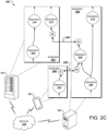
- the first send node S 1 may as shown in FIG. 2C be allocated to the third device included in machine 130, along with node 202, as part of subgraph 240 that the system has assigned to the third device.
- the first receive node R 1 and second send node S 2 may be allocated to the second device included in machine 126, along with nodes 206, 208, and 210, as part of subgraph 246 that the system has assigned to the second device.
- the second receive node R 2 may be allocated to the first device included in machine 132, along with nodes 204, 212, and 214, as part of subgraph 242 that the system has assigned to the first device.
- the operation represented by the first send node S 1 includes a relaying of the output of node 202 to the first receive node R 1 .
- this exchange occurs by way of channel 220B over a network 215 to which machines 130 and 126 have access.
- Network 215 may be similar to network 114 as described above in association with FIG. 1 .
- the protocol leveraged to conduct this communication is a remote direct memory access RDMA protocol.
- the operation represented by the first receive node R 1 include a passing of the output of the operation represented by node 202 that it receives from the first send node S 1 along as an input to node 208.
- the operation represented by the second send node S 2 include a relaying of the output of the operation represented by the node 208 to the second receive node R 2 .
- this exchange occurs by way of channel 230B over the network 215 to which machines 132 and 126 have access.
- the protocol leveraged to conduct this communication is a remote direct memory access RDMA protocol.
- the operation represented by the second receive node R 2 in turn, include a passing of the output of the operation represented by the node 208 that it receives from the second send node S 2 along as an input to node 212.
- FIG. 3 is a flow diagram of a process 300 provided through execution of send and receive nodes included in a computational graph.
- the process 300 will be described as being performed by a system of one or more computers located in one or more locations.
- the computational graphs and operations described in association with process 300 may be those which have been described above.
- the process 300 may be performed through the execution of one or more portions of a computational graph as provided by system 100 as described above in association with FIG. 1 .
- the operations represented by send and receive nodes may yield bidirectional communication between the devices to which they are assigned. If bidirectional communication is provided, operations 330 and 340 represented by send and receive nodes S 3 and R 3 , respectively, use a remote direct memory access RDMA protocol for such bidirectional communication (332 and 342).
- the operations 330 represented by send node S 3 may then act to determine whether output of an operation of upstream node 310 has been provided (310). Such output may include a tensor produced by way of execution of a subgraph that includes node 310 and send node S 3 by an assigned device. Once provided, operations 330 represented by send node S 3 act to provide the output of the operation represented by node 310 as input to the operations 340 represented by receive node R 3 , which in turn acts to provide the same as input to the operation represented by node 320.
- Execution of operations 340 represented by receive node R 3 may involve sending one or more messages to the corresponding send node S 3 (344). Such messages may serve as indication that the subgraph to which the receive node R 3 belongs is ready to receive input by way of execution of corresponding send node S 3 . In this way, these messages can be seen as a request to receive data output by one or more upstream operations.
- the operations 340 represented by receive node R 3 receive input from send node S 3 that includes the output of the operation represented by node 310.
- the operations 330 represented by send node S 3 may include a relaying of data in response to receipt of such messages.
- the operations 330 represented by send node S 3 do not act to relay the output of the operation represented by node 310 until such a message has been received (336). In this way, the flow of information between devices may be regulated so as to ensure that tensors are successfully exchanged.
- the output of the operation represented by node 310 may be cached or otherwise stored in one or more memory regions local to the device that is executing the send node S 3 (337). In some implementations, this output of the operation may be stored elsewhere on a machine to which the device belongs, or on one or more network-accessible devices.
- the stored output of the operation is communicated to the party associated with receive node R 3 (336 to 338) and subsequently flushed or otherwise deleted from memory.
- the operations represented by receive node R 3 act to provide such output as input to the operation represented by downstream node 320 (348).
- operations 330 and 340 as represented by send and receive nodes S 3 and R 3 may be leveraged in handling all incoming and/or outgoing communications of a given device.
- the operations 340 represented by receive node R 3 act to receive incoming communication from operations 330 represented by send node S 3 , and also may act to receive incoming communication from operations represented by one or more other send nodes.
- the operations 330 represented by send node S 3 act to provide outgoing communications as input to operations 340 represented by receive node R 3 , and also may act to provide operations represented by one or more other receive nodes.
- operations 330 and 340 represented by send and receive nodes S 3 and R 3 may act to provide hub-like functions to the devices to which they are assigned.
- Send and receive nodes S 3 and R 3 may serve to compartmentalize subgraphs in a manner that allows for a neural network or a portion of a neural network represented by such subgraphs to be trained on one device, and later on allocated to another device.
- Send and receive nodes S 3 and R 3 may also allow neural networks or portions of neural networks represented by one or more subgraphs to be trained or tested in new ways.
- the operations 340 represented by receive node R 3 may provide an input to the operation represented by node 320 that simulates a tensor being output by the operation represented by node 310 in order to train one or more portions of the computational graph downstream from the receive node R 3 .
- a client device such as client device 102 described above in reference to FIG.
- the client device may execute an operation represented by a specialized node that provides a predetermined tensor as output to operations 330, which may also be executed on the client device.
- a specialized node can be seen as a substitute for nodes that are upstream in a computational graph from that of receive node R 3 and node 320. In this way, users may be able to remotely test and/or train a neural network or a portion of a neural network represented by one or more downstream subgraphs by executing an operation represented by a specialized node and operations 330 on their client device.
- the tensor output by an operation represented by a specialized node of this type may, for example, be static, user-defined, randomly generated, or determined based on one or more characteristics of the devices, machines, nodes, and networks associated with the execution of the subgraphs at hand.
- data exchanged between devices in association with send and receive nodes S 3 and R 3 may be compressed. That is, the operations 330 represented by send node S 3 may act to perform one or more compression processes upon the output of the operation represented by node 310. Similarly, the operations 340 represented by receive node R 3 may act to perform one or more decompression processes upon compressed data provided as output by way of execution of the operations 330 represented by send node S 3 .
- the compression operations performed may include any conventional compression algorithm that is appropriate for transmitting data between the two devices. For example, the data exchanged between devices may be downconverted, truncated, or a combination thereof. Similarly, values conveyed by such data may also be subject to probabilistic rounding.
- Such compression operations may be selected based on one or more characteristics of the devices, machines, nodes, and networks associated with the execution of the subgraphs at hand. For example, compression operations may be selected based on the machine learning model's noise tolerance. Although compression has been described in association with operations 330 and 340, it is to be understood that such operations may leverage any of various signal processing and conditioning techniques.
- FIGS. 4A-B depict two portions of computational graphs 400A and 400B that include send and receive nodes and are allocated to devices. It can be seen in figure 4A that the send node included in computational graph 400A has been assigned to device 412A, which in figure 4A is a GPU, and that the receive node included in computational graph 400A has been assigned to device 414A, which in figure 4A is also a GPU. In the system of figure 4A , which is not an embodiment of this disclosure, GPU 412A and GPU 414A reside within a same machine 410A.
- the particular communication protocol to be used may be determined through execution of the operations represented by send and receive nodes after subgraph allocation. Such determinations may be made, for instance, on the basis of address information known to these operations.
- GPU 412A and GPU 414A may execute operations associated with the send and receive nodes which indicate that the two devices both reside within machine 410A, and subsequently coordinate communications under RPC.
- a communication protocol may be predetermined and indicated within the operations represented by each send and receive node at the time of their insertion.
- each communication protocol may be determined in a manner similar to that which has been described above.
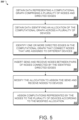
- FIG. 5 is a flow diagram of a process 500 for modifying a computational graph to include send and receive nodes.
- the process 500 will be described as being performed by a computational graph system implemented by one or more computers located in one or more locations.
- the computational graph system 100 of FIG. 1A appropriately programmed, can perform the process 500.
- the computational graph system obtains data representing a computational graph that includes multiple nodes and directed edge (502). For example, a computational graph is obtained by the computational graph system after a receiving a request from one or more client devices.
- each node in the computational graph is an instantiation of an operation.
- the computational graph system obtains data identifying an allocation of the computational graph across multiple devices (504). For example, the computational graph system may determine how each node included in the obtained computational graph is to be assigned across multiple available devices. In some implementations, this may include obtaining data identifying an allocation of the computational graph across hardware resources included in one or more machines.
- the computational graph system modifies the computational graph. To do this it identifies one or more directed edges in the computational graph that connect nodes that are assigned to different devices (506). That is, the computational graph system identifies one or more cross-device directed edges.
- the computational graph system inserts send and receive nodes between pairs of nodes connected by the identified directed edges (508).
- the computational graph system replaces each identified cross-device directed edge with a pair of send and receive nodes that are connected by a bidirectional bridge. In doing so, the system may further insert a directed edge between the send node and a respective first node, as well as insert a directed edge between the receive node and a respective second node.
- Each send node represents an operation that receives, as input, an output of the operation represented by a respective first node, and provides the output of the operation represented by the respective first node, as output, to the receive node.
- the output of the operation represented by the respective first node may be a tensor, for example.
- each receive node represents an operation that receives, as input, the output of the operation represented by the send node, and provides the output of the operation represented by the send node, as output, to a respective second node.
- the operation represented by the receive node may further provide requests for output of the operation represented by the send node, as output, to the send node.
- the operation represented by the send node may provide the output of the operation represented by the respective first node, as output, to the receive node in response to one or more requests received from the receive node.
- data may be independently exchanged between operations represented by each node in a pair of send and receive nodes.
- each node in a pair of send and receive nodes may represent an operation that receives, as input, an output of the operation represented by the other node in the pair communicated according to an RDMA protocol.
- the computational graph system modifies the allocation to assign the send and receive nodes to devices (510). For example, the computational graph system may assign each send node to the same device as the node upstream from the send node, and likewise may assign each receive node to the same device as the node downstream from the receive node.
- the computational graph system assigns operations represented by the nodes to the multiple device according to the modified allocation (512). For example, the computational graph system may request that each of multiple devices perform the operations included in a respective subgraph. In some implementations, the computational graph system may partition the computational graph into multiple subgraphs.
- Embodiments of the subject matter and the functional operations described in this specification can be implemented in digital electronic circuitry, in tangibly-embodied computer software or firmware, in computer hardware, including the structures disclosed in this specification and their structural equivalents, or in combinations of one or more of them.
- Embodiments of the subject matter described in this specification can be implemented as one or more computer programs, i.e., one or more modules of computer program instructions encoded on a computer-readable program carrier, for example a tangible non-transitory program carrier, for execution by, or to control the operation of, data processing apparatus.
- the program instructions can be encoded on an artificially-generated propagated signal, e.g., a machine-generated electrical, optical, or electromagnetic signal, that is generated to encode information for transmission to suitable receiver apparatus for execution by a data processing apparatus.
- the computer storage medium can be a machine-readable storage device, a machine-readable storage substrate, a random or serial access memory device, or a combination of one or more of them. The computer storage medium is not, however, a propagated signal.
- data processing apparatus encompasses all kinds of apparatus, devices, and machines for processing data, including by way of example a programmable processor, a computer, or multiple processors or computers.
- the apparatus can include special purpose logic circuitry, e.g., an FPGA (field programmable gate array) or an ASIC (application-specific integrated circuit).
- the apparatus can also include, in addition to hardware, code that creates an execution environment for the computer program in question, e.g., code that constitutes processor firmware, a protocol stack, a database management system, an operating system, or a combination of one or more of them.
- a computer program (which may also be referred to or described as a program, software, a software application, a module, a software module, a script, or code) can be written in any form of programming language, including compiled or interpreted languages, or declarative or procedural languages, and it can be deployed in any form, including as a stand-alone program or as a module, component, subroutine, or other unit suitable for use in a computing environment.
- a computer program may, but need not, correspond to a file in a file system.
- a program can be stored in a portion of a file that holds other programs or data, e.g., one or more scripts stored in a markup language document, in a single file dedicated to the program in question, or in multiple coordinated files, e.g., files that store one or more modules, sub-programs, or portions of code.
- a computer program can be deployed to be executed on one computer or on multiple computers that are located at one site or distributed across multiple sites and interconnected by a communication network.
- an “engine,” or “software engine,” refers to a software implemented input/output system that provides an output that is different from the input.
- An engine can be an encoded block of functionality, such as a library, a platform, a software development kit ("SDK”), or an object.
- SDK software development kit
- Each engine can be implemented on any appropriate type of computing device, e.g., servers, mobile phones, tablet computers, notebook computers, music players, e-book readers, laptop or desktop computers, PDAs, smart phones, or other stationary or portable devices, that includes one or more processors and computer readable media. Additionally, two or more of the engines may be implemented on the same computing device, or on different computing devices.
- the processes and logic flows described in this specification can be performed by one or more programmable computers executing one or more computer programs to perform functions by operating on input data and generating output.
- the processes and logic flows can also be performed by, and apparatus can also be implemented as, special purpose logic circuitry, e.g., an FPGA (field programmable gate array) or an ASIC (application-specific integrated circuit).
- special purpose logic circuitry e.g., an FPGA (field programmable gate array) or an ASIC (application-specific integrated circuit).
- Computers suitable for the execution of a computer program include, by way of example, can be based on general or special purpose microprocessors or both, or any other kind of central processing unit.
- a central processing unit will receive instructions and data from a read-only memory or a random access memory or both.
- the essential elements of a computer are a central processing unit for performing or executing instructions and one or more memory devices for storing instructions and data.
- a computer will also include, or be operatively coupled to receive data from or transfer data to, or both, one or more mass storage devices for storing data, e.g., magnetic, magneto-optical disks, or optical disks.
- mass storage devices for storing data, e.g., magnetic, magneto-optical disks, or optical disks.
- a computer need not have such devices.
- a computer can be embedded in another device, e.g., a mobile telephone, a personal digital assistant (PDA), a mobile audio or video player, a game console, a Global Positioning System (GPS) receiver, or a portable storage device, e.g., a universal serial bus (USB) flash drive, to name just a few.
- PDA personal digital assistant
- GPS Global Positioning System
- USB universal serial bus
- Computer-readable media suitable for storing computer program instructions and data include all forms of non-volatile memory, media and memory devices, including by way of example semiconductor memory devices, e.g., EPROM, EEPROM, and flash memory devices; magnetic disks, e.g., internal hard disks or removable disks; magneto-optical disks; and CD-ROM and DVD-ROM disks.
- semiconductor memory devices e.g., EPROM, EEPROM, and flash memory devices
- magnetic disks e.g., internal hard disks or removable disks
- magneto-optical disks e.g., CD-ROM and DVD-ROM disks.
- the processor and the memory can be supplemented by, or incorporated in, special purpose logic circuitry.
- a computer having a display device, e.g., a CRT (cathode ray tube) monitor, an LCD (liquid crystal display) monitor, or an OLED display, for displaying information to the user, as well as input devices for providing input to the computer, e.g., a keyboard, a mouse, or a presence sensitive display or other surface.
- a display device e.g., a CRT (cathode ray tube) monitor, an LCD (liquid crystal display) monitor, or an OLED display
- input devices for providing input to the computer, e.g., a keyboard, a mouse, or a presence sensitive display or other surface.
- Other kinds of devices can be used to provide for interaction with a user as well; for example, feedback provided to the user can be any form of sensory feedback, e.g., visual feedback, auditory feedback, or tactile feedback; and input from the user can be received in any form, including acoustic, speech, or tactile input.
- a computer can interact with a user
- Examples of the subject matter described in this specification can be implemented in a computing system that includes a back end component, e.g., as a data server, or that includes a middleware component, e.g., an application server, or that includes a front end component, e.g., a client computer having a graphical user interface or a Web browser through which a user can interact with an implementation of the subject matter described in this specification, or any combination of one or more such back end, middleware, or front end components.
- the components of the system can be interconnected by any form or medium of digital data communication, e.g., a communication network. Examples of communication networks include a local area network (“LAN”) and a wide area network (“WAN”), e.g., the Internet.
- LAN local area network
- WAN wide area network
- the computing system can include clients and servers.
- a client and server are generally remote from each other and typically interact through a communication network.
- the relationship of client and server arises by virtue of computer programs running on the respective computers and having a client-server relationship to each other.
Landscapes
- Engineering & Computer Science (AREA)
- Theoretical Computer Science (AREA)
- Physics & Mathematics (AREA)
- Software Systems (AREA)
- General Physics & Mathematics (AREA)
- General Engineering & Computer Science (AREA)
- Mathematical Physics (AREA)
- Data Mining & Analysis (AREA)
- Life Sciences & Earth Sciences (AREA)
- Biomedical Technology (AREA)
- Biophysics (AREA)
- Health & Medical Sciences (AREA)
- Computing Systems (AREA)
- Computational Linguistics (AREA)
- Molecular Biology (AREA)
- General Health & Medical Sciences (AREA)
- Evolutionary Computation (AREA)
- Artificial Intelligence (AREA)
- Mathematical Analysis (AREA)
- Computational Mathematics (AREA)
- Mathematical Optimization (AREA)
- Pure & Applied Mathematics (AREA)
- Neurology (AREA)
- Algebra (AREA)
- Databases & Information Systems (AREA)
- Information Retrieval, Db Structures And Fs Structures Therefor (AREA)
- Debugging And Monitoring (AREA)
- Data Exchanges In Wide-Area Networks (AREA)
Description
- This specification relates to modifying computational graphs representing neural networks and/or to use of a modified computational graph for processing a model input.
- Neural networks are machine learning models that employ one or more layers of models to generate an output, e.g., one or more classifications, for a received input. Some neural networks include one or more hidden layers in addition to an output layer. The output of each hidden layer is used as input to the next layer in the network, i.e., the next hidden layer or the output layer of the network. Each layer of the network generates an output from a received input in accordance with current values of a respective set of parameters for the layer.
- The layers of a neural network can be processed by an individual device. The device can have a processor that performs operations, e.g., generating outputs at a layer from inputs, and stores outputs from the operations in memory. Due to the large number and size of operations generally required to generate the outputs in the neural network, one device can take a significant amount of time to process the layers of the neural network.
-
US 2006/095722 proposes apparatus for processing data under control of a program having program instructions and subgraph suggestion information identifying respective sequences of program instructions corresponding to computational subgraphs identified within said program, said apparatus comprising: a memory operable to store a program formed of separate program instructions; processing logic operable to execute respective separate program instructions from said program; and accelerator logic operable in response to reaching an execution point within said program associated with a subgraph suggestion to execute a sequence of program instructions corresponding to said subgraph suggestion as an accelerated operation instead of executing said sequence of program instructions as respective separate program instructions with said processing logic. -
US 2015/007182 proposes techniques and constructs to improve execution speed of distributed iterative computation using heterogeneous specialized resources including, for example, processors and accelerators. Iteration over an arbitrary sub-graph without loop unrolling including for algorithms with data-dependent loop termination and large iteration counts, including as a result of nested iteration, are supported in a resource-efficient manner without adding vertices to a dataflow graph to represent iteration constructs. Instead, some or all of the existing vertices within the sub-graph that is to be iterated upon based on having additional and/or modified ports and channels associated with them. - In general, this specification describes a system for modifying computational graphs representing neural networks and other machine learning models.
- Particular embodiments of the subject matter described in this specification can be implemented so as to realize one or more of the following advantages. Operations of a neural network, e.g., operations to generate an inference from an input or to train the neural network, can be represented as a computational graph of nodes and directed edges. A system processes this computational graph representation to efficiently perform the operations of the neural network. By way of illustration, subgraphs of the computational graph can be assigned to unique devices, each of which performs operations in the respective subgraph, to reduce an overall time required to perform operations of the neural network. Communication between unique devices performing operations of different subgraphs of the computational graph can be handled efficiently by inserting send and receive nodes into each subgraph. When executed, the operations that these send and receive nodes represent may enable pairs of unique devices to conduct communication with each other in a self-sufficient manner. This shifts the burden of coordinating communication away from the backend, which affords the system that processes this computational graph representation the opportunity to perform one or more other processes while devices are executing subgraphs. Send and receive nodes serve to compartmentalize subgraphs in a manner that allows for a neural network or a portion of a neural network represented by such subgraphs to be trained on one device, and later on allocated to another device. For at least these reasons, modifying computational graphs to include pairs of send and receive nodes may help reduce time costs and the amount of network communication required to process a computational graph in a distributed fashion.
- In an aspect, the subject matter described in this specification is embodied in a method as defined in the appended
claim 1. The method includes the actions of obtaining, at a computational graph system and from a client, data representing a computational graph, the computational graph including a plurality of nodes and directed edges, where each node represents a respective operation, and where each directed edge connects a respective first node to a respective second node that represents an operation that receives, as input, an output of an operation represented by the respective first node, obtaining, , at the computational graph system, data identifying an allocation of the computational graph across a plurality of devices, where the allocation assigns each node in the computational graph to a respective device of the plurality of devices, and wherein each device is a hardware resource that performs operations independent of the other devices and comprises a respective processing unit; modifying, by the computational graph system, the computational graph, by: identifying one or more cross-device directed edges in the computational graph, where each cross-device directed edge is a directed edge that connects a respective first node to a respective second node that is assigned to a different device than the respective first node in the allocation, and for each cross-device directed edge, inserting a send node between the respective first node and the respective second node in the computational graph, inserting a receive node between the send node and the respective second node in the operation graph, and modifying the allocation to assign the send node to the same device as the respective first node and the receive node to the same device as the respective second node, and assigning the operations represented by the nodes in the computational graph to the plurality of devices according to the modified allocation; wherein assigning the operation represented by the nodes in the computational graph to the plurality of devices comprises assigning the operations represented by the send node to a device on a first physical machine and assigning the operations represented by the receive node to a device on a second physical machine different from the first physical machine, and wherein: the send node represents an operation that (i) receives, as input, an output of the operation represented by the respective first node, and (ii) provides the output of the operation represented by the respective first node, as output communicated according to a remote direct memory access RDMA protocol, to the receive node; and the receive node represents an operation that (i) receives, as input, the output of the operation represented by the send node communicated according to the remote direct memory access RDMA protocol, and (ii) provides the output of the operation represented by the send node, as output, to the respective second node. The methods are computer-implemented methods. - In an implementation the method further comprises: receiving a model input; and processing the model input according to operations represented by the modified computational graph.
- In these aspects the computational graph may be a representation of a machine learning model such as, for example, a neural network.
- Another aspect includes a system comprising: one or more data processing apparatus; and a computer-readable storage device having stored thereon instructions that, when executed by the one or more data processing apparatus, cause the one or more data processing apparatus to implement a computational graph system configured to perform operations comprising a method of the first aspect. A system of one or more data processing apparatus can be so configured by virtue of software, firmware, hardware, or a combination of them installed on the system that in operation cause the system to perform the actions. One or more computer programs can be so configured by virtue of having instructions that, when executed by data processing apparatus, cause the apparatus to implement a computational graph system configured to perform the actions. Another aspect includes a computer-readable storage device having instructions stored thereon that, when executed by a computing device, cause the computing device to implement a computational graph system configured to perform operations comprising a method of the first aspect,
- In some implementations of a method of the first aspect, the operation represented by the receive node may further (iii) provide requests for output of the operation represented by the send node, as output, to the send node, and the operation represented by the send node may further (ii) provide the output of the operation represented by the respective first node, as output, to the receive node in response to one or more requests received from the receive node. In other implementation, the output of the operation represented by the respective first node may be a tensor.
- In some implementations of a method of the first aspect, inserting the send node between the respective first node and the respective second node in the computational graph further may include, for each cross-device directed edge, inserting a directed edge between the send node and the respective first node. In addition, inserting the receive node between the send node and the respective second node in the operation graph further may include, for each cross-device directed edge, inserting a directed edge between the receive node and the respective second node.
- In some implementations of a method of the first aspect, data may be independently exchanged between operations represented by each node in a pair of send and receive nodes.
- The details of one or more examples of the subject matter of this specification are set forth in the accompanying drawings and the description below. Other features, aspects, and advantages of the subject matter will become apparent from the description, the drawings, and the claims. It will be appreciated that aspects and implementations can be combined, and that features described in the context of one aspect or implementation can be implemented in the context of other aspects or implementations.
-
-
FIG. 1A illustrates a computational graph system for distributing operations for neural networks represented as computational graphs. -
FIG. 1B is a conceptual diagram for a framework for distributing operations for neural networks represented as computational graphs in a system. -
FIGS. 2A-C illustrate processing computational graphs by a method of the present disclosure. -
FIG. 3 is a flow diagram of a process provided through execution send and receive nodes included in a computational graph. -
FIG. 4A shows portions of computational graphs as allocated to devices via a comparative method. -
FIG. 4B shows portions of computational graphs as allocated to devices via a method of the present disclosure. -
FIG. 5 is a flow diagram of a process for modifying a computational graph. - Like reference numbers and designations in the various drawings indicate like elements.
- This specification generally describes a computational graph system that performs operations represented by a computational graph in a distributed manner. Particularly, this specification describes techniques for modifying computational graphs in a manner which enables seamless communication between devices. Such techniques may help to ensure that each computational graph is collectively executed by multiple devices in an expeditious and effective manner.
- The computational graph includes nodes connected by directed edges. Each node in the computational graph represents an operation. An incoming edge to a node represents a flow of an input into the node, i.e., an input to the operation represented by the node. An outgoing edge from a node represents a flow of an output of the operation represented by the node to be used as an input to an operation represented by another node. Thus, a directed edge connecting a first node in the graph to a second node in the graph indicates that an output generated by the operation represented by the first node is used as an input to the operation represented by the second node.
- Generally, the input and outputs flowing along directed edges in the computational graph are tensors. A tensor is a multidimensional array of numeric values or other values, e.g., strings, having a specific order that corresponds to the dimensionality of the array. For example, a scalar value is a 0th-order tensor, a vector of numeric values is a 1st-order tensor, and a matrix is a 2nd-order tensor.
- In some implementations, the operations represented in the computational graph are neural network operations or operations for a different kind of machine learning model. A neural network is a machine learning model that employs one or more layers of nonlinear units to predict an output for a received input. Some neural networks are deep neural networks that include one or more hidden layers in addition to an output layer. The output of each hidden layer is used as input to another layer in the network, i.e., another hidden layer, the output layer, or both. Some layers of the network generate an output from a received input in accordance with current values of a respective set of parameters, while other layers of the network may not have parameters.
- For example, the operations represented by the computational graph may be operations necessary for the neural network to compute an inference, i.e., to process an input through the layers of the neural network to generate a neural network output for the input. As another example, the operations represented by the computational graph may be operations necessary to train the neural network by performing a neural network training procedure to adjust the values of the parameters of the neural network, e.g., to determine trained values of the parameters from initial values of the parameters. In some cases, e.g., during training of the neural network, the operations represented by the computational graph can include operations performed by multiple replicas of the neural network.
- By way of illustration, a neural network layer that receives an input from a previous layer can use a parameter matrix to perform a matrix multiplication between the parameter matrix and the input. In some cases, this matrix multiplication can be represented as multiple nodes in the computational graph. For example, a matrix multiplication can be divided into multiple multiplication and addition operations, and each operation can be represented by a different node in the computational graph. The operation represented by each node can generate a respective output, which flows on a directed edge to a subsequent node. After the operation represented by a final node generates a result of the matrix multiplication, the result flows, on a directed edge, to another node. The result is equivalent to an output of the neural network layer that performs the matrix multiplication.
- In some other cases, the matrix multiplication is represented as one node in the graph. The operations represented by the node can receive, as inputs, an input tensor on a first directed edge and a weight tensor, e.g., a parameter matrix, on a second directed edge. The node can process, e.g., perform a matrix multiplication of, the input and weight tensors to output, on a third directed edge, an output tensor, which is equivalent to an output of the neural network layer.
- Other neural network operations that may be represented by nodes in the computational graph include other mathematical operations, e.g., subtraction, division, and gradient computations; array operations, e.g., concatenate, splice, split, or rank; and neural network building block operations, e.g., SoftMax, Sigmoid, rectified linear unit (ReLU), or convolutions.
- Representing a neural network as a computational graph provides for a flexible and granular way to efficiently implement the neural network, especially if the operations for the neural network are distributed across multiple devices with different hardware profiles.
-
FIG. 1A illustrates a computational graph system 100 for distributing operations for neural networks represented as computational graphs. The system 100 is implemented as computer programs on one or more computers in one or more locations, in which the systems, components, and techniques described below can be implemented. - A user of a client 102 can request operations be performed on a computational graph representing a neural network. The client 102 can be an application running on a computer.
- As part of the request, the client 102 provides data identifying a computational graph to the system 100 and specifies types of operations to be performed on the computational graph.
- For example, the request can identify a computational graph representing an inference for a particular neural network and can identify an input on which the inference should be performed.
- As another example, the request can identify a computational graph representing a training procedure for a particular neural network and can identify an input, such as training data, on which the training should be performed. In this example, when receiving a request to process a computational graph representing a training procedure, the system 100 can determine modified values for parameters for one or more edges of the computational graph, e.g., using conventional backpropagation or other neural network training techniques. The system 100 can store the modified parameters in memory of a device, and an
executor 106 can retrieve and store, at the system 100, addresses of the modified weights. Upon further requests from the client 102 for inference, training, or other operations requiring the modified weights, the system 100 can access the modified weights using the addresses. - In some cases, the request may specify a response that should be transmitted in response to the request. For example, for a neural network training request, the client 102 can request an indication that the requested neural network training operations have been completed and, optionally, trained values of the parameters of the neural network or an indication of a memory location from which the trained values can be accessed by the client 102. As another example, for a neural network inference request, the client 102 can request output values that represent an inference operation from one or more particular nodes of the computational graph.
- The system 100 performs the operations to generate the particular output by partitioning the operations represented by the computational graph across multiple devices 116-122. The system 100 partitions the operations to the multiple devices 116-122 over a
data communication network 114, e.g., local area network (LAN) or wide area network (WAN). The devices 116-122 perform the operations and, if applicable, return a respective output or indication to the system 100, which can return the requested output or indication to the client 102. - Any devices performing neural network operations, e.g., devices 116-122, can include a memory, e.g., a random access memory (RAM), for storing instructions and data and a processor for executing stored instructions. Generally, each device is a hardware resource that performs operations independent of other devices. For example, each device can have its own processing unit. The devices can be Graphical Processing Units (GPUs) or Central Processing Units (CPUs). By way of illustration, one machine can host one or more devices, e.g., multiple CPUs and GPUs. Examples of such devices and machines can be seen in
FIG. 1B . -
FIG. 1B is a conceptual diagram for a framework for distributing operations for neural networks represented as computational graphs in the system 100. Referring now toFIG. 1B , examples of machines include acomputing device 126,personal computer 128,mobile device 130, andserver 132. Each machine may, for example, include one or more devices, such asGPU 116 andCPU 118. - Each device can also have a respective computational capability. That is, devices can have different amount of memories, processing speed, or other architectural characteristics. Thus, some devices can perform operations that other devices cannot. For example, some operations require a certain amount of memory that only particular devices have, or some devices are configured to only perform a particular type of operation, e.g., inference operations.
- Referring again to
FIG. 1A , asession manager 104 in the system 100 may receive a request from the client 102 to start a session during which operations of the computational graph are performed. Thesession manager 104 manages the set of devices, e.g., devices 116-122, that can perform operations of the computational graph, and can provide aplacer 108 with the set of devices that are available to perform operations. - The
placer 108 determines, for each operation to be performed in the computational graph, a respective target device, e.g.,device 116, that performs the operation, and in some implementations, a time for the respective target device to perform the operation. Some operations can be performed in parallel while other operations require prior operations in the computational graph to be completed, e.g., the other operations process, as inputs, outputs of the prior operations. - After the devices perform the operations allocated by the
placer 108 to generate outputs, theexecutor 106 can retrieve the outputs. Theexecutor 106 can generate an appropriate response to the request, e.g., an output or an indication that the processing has been completed. Then, theexecutor 106 can return the response to the client 102. - The
session manager 104 also provides sets of operations to be performed in the computational graph to theexecutor 106. Theexecutor 106 periodically retrieves runtime statistics from the devices 116-122 related to graph execution of operations. Theexecutor 106 provides the runtime statistics to theplacer 108, which can re-optimize placement and scheduling of further operations. - In operation, the system 100 may receive a request from a client 102 to process a computational graph. For example, the request can be a request to perform a neural network inference represented by the computational graph on a specified input, a request to perform neural network training operations represented by the computational graph on a specified set of training data, or a request to perform other neural network operations represented by the computational graph, as described above.
- Upon receipt of the request, the system 100 obtains data representing the computational graph. In some cases, the data is sent with the request from the client.
By way of illustration, the data representing the graph can be an array of the nodes in the graph. Each node can contain information specifying an operation type, a name, and a list of incoming and outgoing edges to the node. - The system 100 may identify multiple available devices for performing the requested operation. A device may be considered busy if the device is currently performing other operations and cannot be assigned further operations or is otherwise unavailable to perform graph processing operations. The device may be considered available if the device can be assigned further operations, e.g., the further operations can be queued for operation by the device.
- The system 100 partitions the computational graph into multiple subgraphs. Each subgraph includes one or more nodes in the computational graph. The system 100 obtains these subgraphs by breaking up pairs of nodes in the computational graph that are adjacent to each other, but are assigned to different devices.
- The system 100 assigns, for each subgraph, the operations represented by the one or more nodes in the subgraph to a respective available device. In some implementations, the system 100 may assign each subgraph to a device having a computational capability necessary to perform the operations represented by the nodes in the subgraph. In some implementations, the request from the client includes data specified by a user that identifies a particular type of device to perform operations for particular nodes.
- Thus, the system 100 generates an allocation of the computational graph across multiple devices that assigns each node in the computational graph to a respective device of the multiple devices. Each subgraph includes a given group of one or more nodes in the computational graph which, as described above, are be assigned to the same device. One subgraph to device mapping can be seen in
FIG. 1B . In this mapping,subgraphs computational graph 140 are allocated toGPU 116 andCPU 118, respectively.GPU 116 andCPU 118 may reside in a different or a same one of machines 126-132. In operation,GPU 116 andCPU 118 perform the operations represented by the nodes included in the subgraph that the system 100 has assigned to them. - The system 100 may cause the devices to perform the operations of the nodes included in the subgraphs respectively assigned to the devices. In some implementations, the system 100 may send each device a request to start the operations of the nodes included in the subgraph assigned to the respective device. In response to receiving such a request from the system 100, each device may proceed to perform the operations of the nodes included in the subgraph assigned to the device.
- Given that various dependencies may exist between nodes and groups of nodes in the computational graph, it follows that communication between various devices will need to be coordinated in order for such devices to be able to collectively execute the computational graph. For example, a node that represents an operation being executed on a first device may receive, as input, an output of another node that represents an operation being executed on a second, remotely located device. In this example, communication of the output of the operation represented by the other node from the second device to the first device needs to be coordinated in an effective manner in order to ensure proper and timely execution of the computational graph.
- In some examples, the devices may coordinate exchanges of inputs and outputs with one another, as necessary. In these examples, the communication between the devices may occur independent of the system 100. That is, the system 100 may send each device a request to execute the operations of its respective subgraph and, in response to the request, each device proceeds to execute the operations of its respective subgraph in response to the system 100's request, which may include coordinating communication with other devices without additional intervention by the system 100.
- In accordance with the present disclosure, to allow the devices to communicate independently of the system 100, the system 100 modifies the computational graph such that it includes additional nodes that represent communication operations between nodes. In particular, a device's respective subgraph may include a node representing an operation which, when executed by the device, allows the device to seamlessly communicate with another device that is executing a counterpart operation. A received model input may then be processed according to operations represented by the modified computational graph.
- More particularly, the system 100 inserts "send" and "receive" nodes into the computational graph. Each send node represents an operation in which data, such as a tensor, is relayed to a receive node that is assigned to a different device than that of the send node. The system 100 determines the locations in the graph at which to insert pairs of send and receive nodes by identifying one or more cross-device directed edges in the graph. Cross-device directed edges are directed edges in the computational graph that connect nodes in the computational graph that are to be allocated to two different devices. The system 100 may identify such cross-device directed edges while or after determining the allocation of the computational graph. Upon identifying each cross-device directed edge included in the graph, the system 100 modifies the computational graph by splitting each cross-device directed edge and inserting a pair of send and receive nodes in place of the cross-device directed edge. This modification process is described further below in reference to
FIGS. 2A-C . -
FIGS. 2A-C illustrate an example of processing computational graphs by a method of the present disclosure. By way of example, a computational graph system, e.g., the system 100 ofFIG. 1A , can receive a request from a client to, given a set of inputs, compute an inference using thecomputational graph 200A. Thecomputational graph 200A receives input from asource 201 and provides output to asink 215. Thesource 201 and sink 215 may, for example, be one or more other nodes of the computational graph. - The system may, for instance, determine to allocate
computational graph 200A across three different devices. To make this determination the system analyzes thecomputational graph 200A to identify one or more nodes that can be partitioned into subgraphs and allocated to the devices available. For example, the system may determine to allocate a first chain formed bynodes nodes node 202 to a third device. Although other possible chains of nodes are possible, the system can select the chains that minimize the number of subgraphs. - Under this particular allocation, the system identifies directed
edges edges edge 220A connectsnode 202 tonode 208, which the system has determined to allocate to third and second devices, respectively. Similarly, directededge 230A crosses device boundaries by extending fromnode 208, which corresponds to the second device, tonode 212, which corresponds to the first device. - In response to identifying each cross-device directed edge included in
computational graph 200A, the system proceeds to modify thecomputational graph 200A to generate a modified computational graph, e.g., the modified computational graph 200B illustrated inFIG. 2B . More particularly, the system inserts a pair of send and receive nodes betweennodes edge 220A. In similar fashion, the system also inserts a pair of send and receive nodes betweennodes edge 230A. It can be seen that directed edges are also inserted between each send or receive node and each node adjacent to such send or receive node. - Referring now to
FIG. 2B , it can be seen that modified computational graph 200B, which represents a version of thecomputational graph 200A as modified by the system, includes two pairs of send and receive nodes. Specifically, a first send node, S1 has been inserted betweennodes node 208. By these insertions, the system allocates the first send node S1 to the same device as node 202 (i.e., the third device) and allocates the first receive node R1 to the same device as node 208 (i.e., the second device). Abidirectional bridge 220B connects the first send node S1 to the first receive node R1. Thebridge 220B can be seen as representing a communication channel between the first send node S1 and the first receive node R1. - When executed, the operations represented by the first send node S1 and the first receive node R1 enable the second and third devices to communicate in a predetermined manner. Execution of such operations includes the second and third devices adhering to a particular communication protocol (being a remote direct memory access RDMA protocol in a method of the present disclosure). Address information of each respective device and/or node being executed by each respective device may also be built into these operations. In this way, the first send node S1 and the first receive node R1 may encapsulate every communication process that may need to be performed between the second and third devices in order for their respective subgraphs to be satisfactorily executed. These communication processes are described further below in reference to
FIGS. 3 and4A-B . - Similarly, a second send node, S2 has been inserted between
nodes node 212. By these insertions, the system allocates the second send node S2 to the same device as node 208 (i.e., the second device) and allocates the first receive node R1 to the same device as node 208 (i.e., the first device). Abidirectional bridge 230B connects the second send node S2 to the second receive node R2, and can be seen as representing a communication channel between the second send node S2 and the second receive node R2. Much like the first send node S1 and the first receive node R1, the second send node S2 and the second receive node R2 enable communication to be easily coordinated between the second and first devices. - As demonstrated by the modified
computational graph 200C inFIG. 2C , the system 100 modifies the allocation such that each send node is allocated to one respective subgraph and each receive node is allocated to another respective subgraph. For instance, the first send node S1 may as shown inFIG. 2C be allocated to the third device included inmachine 130, along withnode 202, as part ofsubgraph 240 that the system has assigned to the third device. Similarly, the first receive node R1 and second send node S2 may be allocated to the second device included inmachine 126, along withnodes subgraph 246 that the system has assigned to the second device. Furthermore, the second receive node R2 may be allocated to the first device included inmachine 132, along withnodes subgraph 242 that the system has assigned to the first device. - At execution time, the operation represented by the first send node S1 includes a relaying of the output of
node 202 to the first receive node R1. InFIG. 2C this exchange occurs by way ofchannel 220B over anetwork 215 to whichmachines Network 215 may be similar tonetwork 114 as described above in association withFIG. 1 . The protocol leveraged to conduct this communication is a remote direct memory access RDMA protocol. The operation represented by the first receive node R1, in turn, include a passing of the output of the operation represented bynode 202 that it receives from the first send node S1 along as an input tonode 208. - Similarly, the operation represented by the second send node S2 include a relaying of the output of the operation represented by the
node 208 to the second receive node R2. In the example ofFIG. 2C this exchange occurs by way ofchannel 230B over thenetwork 215 to whichmachines node 208 that it receives from the second send node S2 along as an input tonode 212. -
FIG. 3 is a flow diagram of aprocess 300 provided through execution of send and receive nodes included in a computational graph. For convenience, theprocess 300 will be described as being performed by a system of one or more computers located in one or more locations. The computational graphs and operations described in association withprocess 300 may be those which have been described above. For example, theprocess 300 may be performed through the execution of one or more portions of a computational graph as provided by system 100 as described above in association withFIG. 1 . - As mentioned above, the operations represented by send and receive nodes may yield bidirectional communication between the devices to which they are assigned. If bidirectional communication is provided,
operations - The
operations 330 represented by send node S3 may then act to determine whether output of an operation ofupstream node 310 has been provided (310). Such output may include a tensor produced by way of execution of a subgraph that includesnode 310 and send node S3 by an assigned device. Once provided,operations 330 represented by send node S3 act to provide the output of the operation represented bynode 310 as input to theoperations 340 represented by receive node R3, which in turn acts to provide the same as input to the operation represented bynode 320. - Execution of
operations 340 represented by receive node R3 may involve sending one or more messages to the corresponding send node S3 (344). Such messages may serve as indication that the subgraph to which the receive node R3 belongs is ready to receive input by way of execution of corresponding send node S3. In this way, these messages can be seen as a request to receive data output by one or more upstream operations. In the example ofFIG. 3 , theoperations 340 represented by receive node R3 receive input from send node S3 that includes the output of the operation represented bynode 310. - At execution, the
operations 330 represented by send node S3 may include a relaying of data in response to receipt of such messages. In some examples, theoperations 330 represented by send node S3 do not act to relay the output of the operation represented bynode 310 until such a message has been received (336). In this way, the flow of information between devices may be regulated so as to ensure that tensors are successfully exchanged. In these examples, the output of the operation represented bynode 310 may be cached or otherwise stored in one or more memory regions local to the device that is executing the send node S3 (337). In some implementations, this output of the operation may be stored elsewhere on a machine to which the device belongs, or on one or more network-accessible devices. Once a receive node message is received, the stored output of the operation is communicated to the party associated with receive node R3 (336 to 338) and subsequently flushed or otherwise deleted from memory. Upon determining that output from the operation represented by send node S3 has been received as input (346), the operations represented by receive node R3 act to provide such output as input to the operation represented by downstream node 320 (348). - It can be seen that, through the execution of
operations devices executing operations - In some implementations,
operations operations 340 represented by receive node R3 act to receive incoming communication fromoperations 330 represented by send node S3, and also may act to receive incoming communication from operations represented by one or more other send nodes. Similarly, theoperations 330 represented by send node S3 act to provide outgoing communications as input tooperations 340 represented by receive node R3, and also may act to provide operations represented by one or more other receive nodes. In this way,operations - Send and receive nodes S3 and R3 may serve to compartmentalize subgraphs in a manner that allows for a neural network or a portion of a neural network represented by such subgraphs to be trained on one device, and later on allocated to another device. Send and receive nodes S3 and R3 may also allow neural networks or portions of neural networks represented by one or more subgraphs to be trained or tested in new ways. For example, the
operations 340 represented by receive node R3 may provide an input to the operation represented bynode 320 that simulates a tensor being output by the operation represented bynode 310 in order to train one or more portions of the computational graph downstream from the receive node R3. In some implementations, a client device, such as client device 102 described above in reference toFIG. 1 , may be leveraged to provide receive node R3 with such an input. In these implementations, the client device may execute an operation represented by a specialized node that provides a predetermined tensor as output tooperations 330, which may also be executed on the client device. Such a specialized node can be seen as a substitute for nodes that are upstream in a computational graph from that of receive node R3 andnode 320. In this way, users may be able to remotely test and/or train a neural network or a portion of a neural network represented by one or more downstream subgraphs by executing an operation represented by a specialized node andoperations 330 on their client device. The tensor output by an operation represented by a specialized node of this type may, for example, be static, user-defined, randomly generated, or determined based on one or more characteristics of the devices, machines, nodes, and networks associated with the execution of the subgraphs at hand. - In some implementations, data exchanged between devices in association with send and receive nodes S3 and R3 may be compressed. That is, the
operations 330 represented by send node S3 may act to perform one or more compression processes upon the output of the operation represented bynode 310. Similarly, theoperations 340 represented by receive node R3 may act to perform one or more decompression processes upon compressed data provided as output by way of execution of theoperations 330 represented by send node S3. The compression operations performed may include any conventional compression algorithm that is appropriate for transmitting data between the two devices. For example, the data exchanged between devices may be downconverted, truncated, or a combination thereof. Similarly, values conveyed by such data may also be subject to probabilistic rounding. Such compression operations may be selected based on one or more characteristics of the devices, machines, nodes, and networks associated with the execution of the subgraphs at hand. For example, compression operations may be selected based on the machine learning model's noise tolerance. Although compression has been described in association withoperations - As described above, the communication protocols leveraged by operations represented by pairs of send and receive nodes may depend on one or more characteristics of the devices, machines, nodes, and networks associated with the execution of the subgraphs at hand.
FIGS. 4A-B depict two portions ofcomputational graphs figure 4A that the send node included incomputational graph 400A has been assigned todevice 412A, which infigure 4A is a GPU, and that the receive node included incomputational graph 400A has been assigned todevice 414A, which infigure 4A is also a GPU. In the system offigure 4A , which is not an embodiment of this disclosure,GPU 412A andGPU 414A reside within asame machine 410A. Since devices that the send and receive nodes ofcomputational graph 400A are both GPUs and both reside within asame machine 410A, it may be advantageous for their exchanges to be conducted under a remote procedure call (RPC) or other localized request/response protocol. - In comparative methods, the particular communication protocol to be used may be determined through execution of the operations represented by send and receive nodes after subgraph allocation. Such determinations may be made, for instance, on the basis of address information known to these operations. In
figure 4A ,GPU 412A andGPU 414A may execute operations associated with the send and receive nodes which indicate that the two devices both reside withinmachine 410A, and subsequently coordinate communications under RPC. In other comparative methods, a communication protocol may be predetermined and indicated within the operations represented by each send and receive node at the time of their insertion. In these comparative methods, each communication protocol may be determined in a manner similar to that which has been described above. - In the example of
fig. 4B it can be seen that the send node included incomputational graph 400B has been assigned todevice 422B, which may be a CPU or GPU, and that the receive node included incomputational graph 400B has been assigned todevice 442B, which may also be a CPU or GPU.Device 422B resides withmachine 420B anddevice 442B resides with machine 440B. In this example, exchanges betweendevices devices -
FIG. 5 is a flow diagram of aprocess 500 for modifying a computational graph to include send and receive nodes. For convenience, theprocess 500 will be described as being performed by a computational graph system implemented by one or more computers located in one or more locations. For example, the computational graph system 100 ofFIG. 1A , appropriately programmed, can perform theprocess 500. - In the method of
fig. 5 the computational graph system obtains data representing a computational graph that includes multiple nodes and directed edge (502). For example, a computational graph is obtained by the computational graph system after a receiving a request from one or more client devices. In some examples, each node in the computational graph is an instantiation of an operation. - The computational graph system obtains data identifying an allocation of the computational graph across multiple devices (504). For example, the computational graph system may determine how each node included in the obtained computational graph is to be assigned across multiple available devices. In some implementations, this may include obtaining data identifying an allocation of the computational graph across hardware resources included in one or more machines.
- The computational graph system modifies the computational graph. To do this it identifies one or more directed edges in the computational graph that connect nodes that are assigned to different devices (506). That is, the computational graph system identifies one or more cross-device directed edges.
- The computational graph system inserts send and receive nodes between pairs of nodes connected by the identified directed edges (508). The computational graph system replaces each identified cross-device directed edge with a pair of send and receive nodes that are connected by a bidirectional bridge. In doing so, the system may further insert a directed edge between the send node and a respective first node, as well as insert a directed edge between the receive node and a respective second node.
- Each send node, for instance, represents an operation that receives, as input, an output of the operation represented by a respective first node, and provides the output of the operation represented by the respective first node, as output, to the receive node. The output of the operation represented by the respective first node may be a tensor, for example. Similarly, each receive node represents an operation that receives, as input, the output of the operation represented by the send node, and provides the output of the operation represented by the send node, as output, to a respective second node. In some implementations, the operation represented by the receive node may further provide requests for output of the operation represented by the send node, as output, to the send node. In these implementations, the operation represented by the send node may provide the output of the operation represented by the respective first node, as output, to the receive node in response to one or more requests received from the receive node.
- In some implementations, data may be independently exchanged between operations represented by each node in a pair of send and receive nodes. In some instances, each node in a pair of send and receive nodes may represent an operation that receives, as input, an output of the operation represented by the other node in the pair communicated according to an RDMA protocol.
- The computational graph system modifies the allocation to assign the send and receive nodes to devices (510). For example, the computational graph system may assign each send node to the same device as the node upstream from the send node, and likewise may assign each receive node to the same device as the node downstream from the receive node.
- The computational graph system assigns operations represented by the nodes to the multiple device according to the modified allocation (512). For example, the computational graph system may request that each of multiple devices perform the operations included in a respective subgraph. In some implementations, the computational graph system may partition the computational graph into multiple subgraphs.
- Embodiments of the subject matter and the functional operations described in this specification can be implemented in digital electronic circuitry, in tangibly-embodied computer software or firmware, in computer hardware, including the structures disclosed in this specification and their structural equivalents, or in combinations of one or more of them. Embodiments of the subject matter described in this specification can be implemented as one or more computer programs, i.e., one or more modules of computer program instructions encoded on a computer-readable program carrier, for example a tangible non-transitory program carrier, for execution by, or to control the operation of, data processing apparatus. Alternatively or in addition, the program instructions can be encoded on an artificially-generated propagated signal, e.g., a machine-generated electrical, optical, or electromagnetic signal, that is generated to encode information for transmission to suitable receiver apparatus for execution by a data processing apparatus. The computer storage medium can be a machine-readable storage device, a machine-readable storage substrate, a random or serial access memory device, or a combination of one or more of them. The computer storage medium is not, however, a propagated signal.
- The term "data processing apparatus" encompasses all kinds of apparatus, devices, and machines for processing data, including by way of example a programmable processor, a computer, or multiple processors or computers. The apparatus can include special purpose logic circuitry, e.g., an FPGA (field programmable gate array) or an ASIC (application-specific integrated circuit). The apparatus can also include, in addition to hardware, code that creates an execution environment for the computer program in question, e.g., code that constitutes processor firmware, a protocol stack, a database management system, an operating system, or a combination of one or more of them.
- A computer program (which may also be referred to or described as a program, software, a software application, a module, a software module, a script, or code) can be written in any form of programming language, including compiled or interpreted languages, or declarative or procedural languages, and it can be deployed in any form, including as a stand-alone program or as a module, component, subroutine, or other unit suitable for use in a computing environment. A computer program may, but need not, correspond to a file in a file system. A program can be stored in a portion of a file that holds other programs or data, e.g., one or more scripts stored in a markup language document, in a single file dedicated to the program in question, or in multiple coordinated files, e.g., files that store one or more modules, sub-programs, or portions of code. A computer program can be deployed to be executed on one computer or on multiple computers that are located at one site or distributed across multiple sites and interconnected by a communication network.
- As used in this specification, an "engine," or "software engine," refers to a software implemented input/output system that provides an output that is different from the input. An engine can be an encoded block of functionality, such as a library, a platform, a software development kit ("SDK"), or an object. Each engine can be implemented on any appropriate type of computing device, e.g., servers, mobile phones, tablet computers, notebook computers, music players, e-book readers, laptop or desktop computers, PDAs, smart phones, or other stationary or portable devices, that includes one or more processors and computer readable media. Additionally, two or more of the engines may be implemented on the same computing device, or on different computing devices.
- The processes and logic flows described in this specification can be performed by one or more programmable computers executing one or more computer programs to perform functions by operating on input data and generating output. The processes and logic flows can also be performed by, and apparatus can also be implemented as, special purpose logic circuitry, e.g., an FPGA (field programmable gate array) or an ASIC (application-specific integrated circuit).
- Computers suitable for the execution of a computer program include, by way of example, can be based on general or special purpose microprocessors or both, or any other kind of central processing unit. Generally, a central processing unit will receive instructions and data from a read-only memory or a random access memory or both. The essential elements of a computer are a central processing unit for performing or executing instructions and one or more memory devices for storing instructions and data. Generally, a computer will also include, or be operatively coupled to receive data from or transfer data to, or both, one or more mass storage devices for storing data, e.g., magnetic, magneto-optical disks, or optical disks. However, a computer need not have such devices. Moreover, a computer can be embedded in another device, e.g., a mobile telephone, a personal digital assistant (PDA), a mobile audio or video player, a game console, a Global Positioning System (GPS) receiver, or a portable storage device, e.g., a universal serial bus (USB) flash drive, to name just a few.
- Computer-readable media suitable for storing computer program instructions and data include all forms of non-volatile memory, media and memory devices, including by way of example semiconductor memory devices, e.g., EPROM, EEPROM, and flash memory devices; magnetic disks, e.g., internal hard disks or removable disks; magneto-optical disks; and CD-ROM and DVD-ROM disks. The processor and the memory can be supplemented by, or incorporated in, special purpose logic circuitry.
- To provide for interaction with a user, embodiments of the subject matter described in this specification can be implemented on a computer having a display device, e.g., a CRT (cathode ray tube) monitor, an LCD (liquid crystal display) monitor, or an OLED display, for displaying information to the user, as well as input devices for providing input to the computer, e.g., a keyboard, a mouse, or a presence sensitive display or other surface. Other kinds of devices can be used to provide for interaction with a user as well; for example, feedback provided to the user can be any form of sensory feedback, e.g., visual feedback, auditory feedback, or tactile feedback; and input from the user can be received in any form, including acoustic, speech, or tactile input. In addition, a computer can interact with a user by sending resources to and receiving resources from a device that is used by the user; for example, by sending web pages to a web browser on a user's client device in response to requests received from the web browser.
- Examples of the subject matter described in this specification can be implemented in a computing system that includes a back end component, e.g., as a data server, or that includes a middleware component, e.g., an application server, or that includes a front end component, e.g., a client computer having a graphical user interface or a Web browser through which a user can interact with an implementation of the subject matter described in this specification, or any combination of one or more such back end, middleware, or front end components. The components of the system can be interconnected by any form or medium of digital data communication, e.g., a communication network. Examples of communication networks include a local area network ("LAN") and a wide area network ("WAN"), e.g., the Internet.
- The computing system can include clients and servers. A client and server are generally remote from each other and typically interact through a communication network. The relationship of client and server arises by virtue of computer programs running on the respective computers and having a client-server relationship to each other.
- While this specification contains many specific implementation details, these should not be construed as limitations on the scope of the disclosure as defined by the appended claims, but rather as descriptions of features that may be specific to particular examples. Certain features that are described in this specification in the context of separate embodiments can also be implemented in combination in a single embodiment. Conversely, various features that are described in the context of a single embodiment can also be implemented in multiple aspects separately or in any suitable subcombination. Moreover, although features may be described above as acting in certain combinations, one or more features from a combination can in some cases be excised from the described combination.
- Similarly, while operations are depicted in the drawings in a particular order, this should not be understood as requiring that such operations be performed in the particular order shown or in sequential order, or that all illustrated operations be performed, to achieve desirable results. In certain circumstances, multitasking and parallel processing may be advantageous. Moreover, the separation of various system modules and components in the examples described above should not be understood as requiring such separation in all examples, and it should be understood that the described program components and systems can generally be integrated together in a single software product or packaged into multiple software products.
- Particular examples of the subject matter have been described. Embodiments are within the scope of the following claims. For example, the actions recited in the claims can be performed in a different order and still achieve desirable results. As one example, the processes depicted in the accompanying figures do not necessarily require the particular order shown, or sequential order, to achieve desirable results. In certain implementations, multitasking and parallel processing may be advantageous.
Claims (9)
- A computer-implemented method comprising:obtaining, at a computational graph system (100) and from a client (102), data representing a computational graph, the computational graph comprising a plurality of nodes and directed edges, wherein each node represents a respective operation, and wherein each directed edge connects a respective first node to a respective second node that represents an operation that receives, as input, an output of an operation represented by the respective first node;obtaining, at the computational graph system (100), data identifying an allocation of the computational graph across a plurality of devices (116 ...122), the devices different from the computational graph system (100), wherein the allocation assigns each node in the computational graph to a respective device of the plurality of devices, and wherein each device is a hardware resource that performs operations independent of the other devices and comprises a respective processing unit;
modifying, by the computational graph system (100), the computational graph, by:identifying one or more cross-device directed edges in the computational graph, wherein each cross-device directed edge is a directed edge that connects a respective first node to a respective second node that is assigned to a different device than the respective first node in the allocation;for each cross-device directed edge:inserting a send node between the respective first node and the respective second node in the computational graph,inserting a receive node between the send node and the respective second node in the operation graph, andmodifying the allocation to assign the send node to the same device as the respective first node and the receive node to the same device as the respective second node; andassigning, by the computational graph system (100), the operations represented by the nodes in the computational graph to the plurality of devices according to the modified allocation; wherein assigning the operation represented by the nodes in the computational graph to the plurality of devices comprises assigning the operations represented by the send node to a device on a first physical machine and assigning the operations represented by the receive node to a device on a second physical machine different from the first physical machine,and wherein:the send node represents an operation that (i) receives, as input, an output of the operation represented by the respective first node, and (ii) provides the output of the operation represented by the respective first node, as output communicated according to a remote direct memory access RDMA protocol, to the receive node; andthe receive node represents an operation that (i) receives, as input, the output of the operation represented by the send node communicated according to the remote direct memory access RDMA protocol, and (ii) provides the output of the operation represented by the send node, as output, to the respective second node. - The method of claim 1, wherein the output of the operation represented by the respective first node is a tensor.
- The method of claim 1 or 2, wherein:the operation represented by the receive node further (iii) provides requests for output of the operation represented by the send node, as output, to the send node; andthe operation represented by the send node further (ii) provides the output of the operation represented by the respective first node, as output, to the receive node in response to one or more requests received from the receive node.
- The method of any preceding claim, wherein: inserting the send node between the respective first node and the respective second node in the computational graph further comprises, for each cross-device directed edge: inserting a directed edge between the send node and the respective first node; and wherein inserting the receive node between the send node and the respective second node in the operation graph further comprises, for each cross-device directed edge: inserting a directed edge between the receive node and the respective second node;
and/or wherein data is independently exchanged between operations represented by each node in a pair of send and receive nodes. - The method of any preceding claim, wherein, during execution of the operations represented by the computational graph by the plurality of devices, the operations represented by each pair of send and receive nodes allow the plurality of devices to independently communicate inputs and outputs of operations represented by other nodes in computational graph across devices in the plurality of devices.
- The method of any preceding claim, further comprising: receiving a model input; and processing the model input according to operations represented by the modified computational graph.
- The method of any preceding claim wherein the computational graph is a representation of a machine learning model.
- A system comprising:one or more data processing apparatus; anda computer-readable storage device having stored thereon instructions that, when executed by the one or more data processing apparatus, cause the one or more data processing apparatus to implement a computational graph system configured to perform operations comprising a method as defined in any one of claims 1 to 7.
- A computer-readable storage device having instructions stored thereon that, when executed by a computing device, cause the computing device to implement a computational graph system configured to perform operations comprising a method as defined in any one of claims 1 to 7.
Priority Applications (1)
| Application Number | Priority Date | Filing Date | Title |
|---|---|---|---|
| EP23185682.4A EP4242845A1 (en) | 2015-10-28 | 2016-10-28 | Modifying computational graphs |
Applications Claiming Priority (3)
| Application Number | Priority Date | Filing Date | Title |
|---|---|---|---|
| US201562247713P | 2015-10-28 | 2015-10-28 | |
| US201562253029P | 2015-11-09 | 2015-11-09 | |
| PCT/US2016/059314 WO2017075346A1 (en) | 2015-10-28 | 2016-10-28 | Modifying computational graphs |
Related Child Applications (1)
| Application Number | Title | Priority Date | Filing Date |
|---|---|---|---|
| EP23185682.4A Division EP4242845A1 (en) | 2015-10-28 | 2016-10-28 | Modifying computational graphs |
Publications (2)
| Publication Number | Publication Date |
|---|---|
| EP3353718A1 EP3353718A1 (en) | 2018-08-01 |
| EP3353718B1 true EP3353718B1 (en) | 2023-07-19 |
Family
ID=57822015
Family Applications (2)
| Application Number | Title | Priority Date | Filing Date |
|---|---|---|---|
| EP16826784.7A Active EP3353718B1 (en) | 2015-10-28 | 2016-10-28 | Modifying computational graphs |
| EP23185682.4A Pending EP4242845A1 (en) | 2015-10-28 | 2016-10-28 | Modifying computational graphs |
Family Applications After (1)
| Application Number | Title | Priority Date | Filing Date |
|---|---|---|---|
| EP23185682.4A Pending EP4242845A1 (en) | 2015-10-28 | 2016-10-28 | Modifying computational graphs |
Country Status (6)
| Country | Link |
|---|---|
| US (4) | US10783435B2 (en) |
| EP (2) | EP3353718B1 (en) |
| JP (2) | JP6636630B2 (en) |
| KR (2) | KR102327615B1 (en) |
| CN (1) | CN108351983A (en) |
| WO (1) | WO2017075346A1 (en) |
Families Citing this family (36)
| Publication number | Priority date | Publication date | Assignee | Title |
|---|---|---|---|---|
| US11615285B2 (en) * | 2017-01-06 | 2023-03-28 | Ecole Polytechnique Federale De Lausanne (Epfl) | Generating and identifying functional subnetworks within structural networks |
| US11037330B2 (en) | 2017-04-08 | 2021-06-15 | Intel Corporation | Low rank matrix compression |
| US11138494B2 (en) * | 2017-05-02 | 2021-10-05 | International Business Machines Corporation | Storage controller acceleration for neural network training and inference |
| US10019668B1 (en) * | 2017-05-19 | 2018-07-10 | Google Llc | Scheduling neural network processing |
| US11138516B2 (en) * | 2017-06-30 | 2021-10-05 | Visa International Service Association | GPU enhanced graph model build and scoring engine |
| WO2019055526A1 (en) | 2017-09-15 | 2019-03-21 | Google Llc | Augmenting neural networks |
| KR102569086B1 (en) | 2017-11-20 | 2023-08-22 | 상하이 캠브리콘 인포메이션 테크놀로지 컴퍼니 리미티드 | Task parallel processing method, device, system, storage medium and computer device |
| US20190286973A1 (en) * | 2018-03-14 | 2019-09-19 | Microsoft Technology Licensing, Llc | Hardware accelerated neural network subgraphs |
| FI130232B (en) * | 2018-04-18 | 2023-05-03 | Meeshkan Oy | Method for distributed information processing and distributed information processing system |
| US11645493B2 (en) | 2018-05-04 | 2023-05-09 | Microsoft Technology Licensing, Llc | Flow for quantized neural networks |
| US11663478B2 (en) | 2018-06-11 | 2023-05-30 | Inait Sa | Characterizing activity in a recurrent artificial neural network |
| US11893471B2 (en) | 2018-06-11 | 2024-02-06 | Inait Sa | Encoding and decoding information and artificial neural networks |
| US11972343B2 (en) | 2018-06-11 | 2024-04-30 | Inait Sa | Encoding and decoding information |
| US10318891B1 (en) * | 2018-07-23 | 2019-06-11 | Google Llc | Geometry encoder |
| US10891758B2 (en) | 2018-07-23 | 2021-01-12 | Google Llc | Geometry encoder |
| CN110766147B (en) * | 2018-07-25 | 2022-10-11 | 赛灵思公司 | Neural network compiler architecture and compiling method |
| US11263529B2 (en) * | 2018-10-10 | 2022-03-01 | Google Llc | Modifying machine learning models to improve locality |
| CN111078624B (en) * | 2018-10-18 | 2022-03-25 | 上海寒武纪信息科技有限公司 | Network-on-chip processing system and network-on-chip data processing method |
| CN111078625B (en) * | 2018-10-18 | 2022-03-29 | 上海寒武纪信息科技有限公司 | Network-on-chip processing system and network-on-chip data processing method |
| KR20200053318A (en) * | 2018-11-08 | 2020-05-18 | 삼성전자주식회사 | System managing calculation processing graph of artificial neural network and method managing calculation processing graph using thereof |
| US10922790B2 (en) * | 2018-12-21 | 2021-02-16 | Intel Corporation | Apparatus and method for efficient distributed denoising of a graphics frame |
| KR20210107531A (en) * | 2018-12-24 | 2021-09-01 | 인텔 코포레이션 | Methods and apparatus for processing a machine learning model in a multi-process web browser environment |
| US11652603B2 (en) | 2019-03-18 | 2023-05-16 | Inait Sa | Homomorphic encryption |
| US11569978B2 (en) | 2019-03-18 | 2023-01-31 | Inait Sa | Encrypting and decrypting information |
| CN111832714B (en) * | 2019-04-19 | 2023-11-17 | 上海寒武纪信息科技有限公司 | Operation method and device |
| US11231961B2 (en) | 2019-05-22 | 2022-01-25 | Fujitsu Limited | Scheduling operations |
| CN110162337B (en) * | 2019-05-31 | 2020-07-03 | 中科寒武纪科技股份有限公司 | Operation method, device and related product |
| CN110210614B (en) * | 2019-05-31 | 2020-08-25 | 中科寒武纪科技股份有限公司 | Operation method, device and related product |
| US11694075B2 (en) * | 2019-09-05 | 2023-07-04 | Alibaba Group Holding Limited | Partitioning control dependency edge in computation graph |
| US11797827B2 (en) | 2019-12-11 | 2023-10-24 | Inait Sa | Input into a neural network |
| US11816553B2 (en) | 2019-12-11 | 2023-11-14 | Inait Sa | Output from a recurrent neural network |
| US11580401B2 (en) | 2019-12-11 | 2023-02-14 | Inait Sa | Distance metrics and clustering in recurrent neural networks |
| US11651210B2 (en) | 2019-12-11 | 2023-05-16 | Inait Sa | Interpreting and improving the processing results of recurrent neural networks |
| US20230229509A1 (en) * | 2020-05-08 | 2023-07-20 | Telefonaktiebolaget Lm Ericsson (Publ) | Configuring a resource for executing a computational operation |
| US11815943B1 (en) * | 2020-06-05 | 2023-11-14 | State Farm Mutual Automobile Insurance Company | Systems and methods for processing using directed acyclic graphs |
| CN112070213A (en) * | 2020-08-28 | 2020-12-11 | Oppo广东移动通信有限公司 | Neural network model optimization method, device, equipment and storage medium |
Family Cites Families (11)
| Publication number | Priority date | Publication date | Assignee | Title |
|---|---|---|---|---|
| US7219085B2 (en) * | 2003-12-09 | 2007-05-15 | Microsoft Corporation | System and method for accelerating and optimizing the processing of machine learning techniques using a graphics processing unit |
| US7343482B2 (en) * | 2004-10-20 | 2008-03-11 | Arm Limited | Program subgraph identification |
| JP2007164504A (en) | 2005-12-14 | 2007-06-28 | Fuji Heavy Ind Ltd | Stream data processing method and stream data processor |
| US7870556B2 (en) | 2006-05-16 | 2011-01-11 | Ab Initio Technology Llc | Managing computing resources in graph-based computations |
| US8923285B2 (en) * | 2008-04-30 | 2014-12-30 | Qualcomm Incorporated | Apparatus and methods for transmitting data over a wireless mesh network |
| KR101048546B1 (en) * | 2009-03-05 | 2011-07-11 | 엔에이치엔(주) | Content retrieval system and method using ontology |
| EP2629247B1 (en) * | 2012-02-15 | 2014-01-08 | Alcatel Lucent | Method for mapping media components employing machine learning |
| US9256823B2 (en) * | 2012-07-27 | 2016-02-09 | Qualcomm Technologies Inc. | Apparatus and methods for efficient updates in spiking neuron network |
| US11061539B2 (en) | 2013-03-15 | 2021-07-13 | The Mathworks, Inc. | Reference nodes in a computational graph |
| US9424079B2 (en) * | 2013-06-27 | 2016-08-23 | Microsoft Technology Licensing, Llc | Iteration support in a heterogeneous dataflow engine |
| JP6007430B2 (en) | 2015-05-20 | 2016-10-12 | 大澤 昇平 | Machine learning model design support device, machine learning model design support method, program for machine learning model design support device |
-
2016
- 2016-10-28 EP EP16826784.7A patent/EP3353718B1/en active Active
- 2016-10-28 EP EP23185682.4A patent/EP4242845A1/en active Pending
- 2016-10-28 JP JP2018521841A patent/JP6636630B2/en active Active
- 2016-10-28 CN CN201680063358.6A patent/CN108351983A/en active Pending
- 2016-10-28 KR KR1020217000978A patent/KR102327615B1/en active IP Right Grant
- 2016-10-28 WO PCT/US2016/059314 patent/WO2017075346A1/en active Application Filing
- 2016-10-28 US US15/338,225 patent/US10783435B2/en active Active
- 2016-10-28 KR KR1020187013806A patent/KR102204887B1/en active IP Right Grant
-
2018
- 2018-04-27 US US15/965,745 patent/US10354186B2/en active Active
-
2019
- 2019-12-17 JP JP2019227507A patent/JP7094262B2/en active Active
-
2020
- 2020-09-09 US US17/015,196 patent/US11087216B2/en active Active
-
2021
- 2021-08-03 US US17/392,690 patent/US20220019896A1/en active Pending
Also Published As
| Publication number | Publication date |
|---|---|
| WO2017075346A1 (en) | 2017-05-04 |
| JP2018533792A (en) | 2018-11-15 |
| US20220019896A1 (en) | 2022-01-20 |
| US11087216B2 (en) | 2021-08-10 |
| US20200401897A1 (en) | 2020-12-24 |
| JP6636630B2 (en) | 2020-01-29 |
| US10783435B2 (en) | 2020-09-22 |
| KR102327615B1 (en) | 2021-11-17 |
| EP3353718A1 (en) | 2018-08-01 |
| EP4242845A1 (en) | 2023-09-13 |
| KR102204887B1 (en) | 2021-01-19 |
| US10354186B2 (en) | 2019-07-16 |
| KR20210008150A (en) | 2021-01-20 |
| US20180247198A1 (en) | 2018-08-30 |
| JP7094262B2 (en) | 2022-07-01 |
| CN108351983A (en) | 2018-07-31 |
| US20170124454A1 (en) | 2017-05-04 |
| JP2020057422A (en) | 2020-04-09 |
| KR20180069881A (en) | 2018-06-25 |
Similar Documents
| Publication | Publication Date | Title |
|---|---|---|
| US11087216B2 (en) | Modifying computational graphs | |
| US11769061B2 (en) | Processing computational graphs | |
| US20210295161A1 (en) | Training neural networks represented as computational graphs | |
| US10373053B2 (en) | Stream-based accelerator processing of computational graphs | |
| US11763146B1 (en) | Processing loops in computational graphs | |
| CN108460458B (en) | Method, system and storage medium for executing computation graph on graphic processing unit |
Legal Events
| Date | Code | Title | Description |
|---|---|---|---|
| STAA | Information on the status of an ep patent application or granted ep patent |
Free format text: STATUS: UNKNOWN |
|
| STAA | Information on the status of an ep patent application or granted ep patent |
Free format text: STATUS: THE INTERNATIONAL PUBLICATION HAS BEEN MADE |
|
| PUAI | Public reference made under article 153(3) epc to a published international application that has entered the european phase |
Free format text: ORIGINAL CODE: 0009012 |
|
| STAA | Information on the status of an ep patent application or granted ep patent |
Free format text: STATUS: REQUEST FOR EXAMINATION WAS MADE |
|
| 17P | Request for examination filed |
Effective date: 20180426 |
|
| AK | Designated contracting states |
Kind code of ref document: A1 Designated state(s): AL AT BE BG CH CY CZ DE DK EE ES FI FR GB GR HR HU IE IS IT LI LT LU LV MC MK MT NL NO PL PT RO RS SE SI SK SM TR |
|
| AX | Request for extension of the european patent |
Extension state: BA ME |
|
| DAV | Request for validation of the european patent (deleted) | ||
| DAX | Request for extension of the european patent (deleted) | ||
| STAA | Information on the status of an ep patent application or granted ep patent |
Free format text: STATUS: EXAMINATION IS IN PROGRESS |
|
| 17Q | First examination report despatched |
Effective date: 20190827 |
|
| STAA | Information on the status of an ep patent application or granted ep patent |
Free format text: STATUS: EXAMINATION IS IN PROGRESS |
|
| RIC1 | Information provided on ipc code assigned before grant |
Ipc: G06N 3/063 20060101ALI20220329BHEP Ipc: G06N 3/04 20060101ALI20220329BHEP Ipc: G06N 3/08 20060101ALI20220329BHEP Ipc: G06F 9/50 20060101ALI20220329BHEP Ipc: G06F 9/54 20060101AFI20220329BHEP |
|
| GRAP | Despatch of communication of intention to grant a patent |
Free format text: ORIGINAL CODE: EPIDOSNIGR1 |
|
| STAA | Information on the status of an ep patent application or granted ep patent |
Free format text: STATUS: GRANT OF PATENT IS INTENDED |
|
| INTG | Intention to grant announced |
Effective date: 20220809 |
|
| GRAJ | Information related to disapproval of communication of intention to grant by the applicant or resumption of examination proceedings by the epo deleted |
Free format text: ORIGINAL CODE: EPIDOSDIGR1 |
|
| STAA | Information on the status of an ep patent application or granted ep patent |
Free format text: STATUS: EXAMINATION IS IN PROGRESS |
|
| REG | Reference to a national code |
Ref document number: 602016081205 Country of ref document: DE Ref country code: DE Ref legal event code: R079 Free format text: PREVIOUS MAIN CLASS: G06N0003063000 Ipc: G06F0009500000 |
|
| INTC | Intention to grant announced (deleted) | ||
| GRAP | Despatch of communication of intention to grant a patent |
Free format text: ORIGINAL CODE: EPIDOSNIGR1 |
|
| STAA | Information on the status of an ep patent application or granted ep patent |
Free format text: STATUS: GRANT OF PATENT IS INTENDED |
|
| RIC1 | Information provided on ipc code assigned before grant |
Ipc: G06N 3/063 20000101ALI20230112BHEP Ipc: G06N 3/084 20230101ALI20230112BHEP Ipc: G06N 3/045 20230101ALI20230112BHEP Ipc: G06F 9/54 20000101ALI20230112BHEP Ipc: G06F 9/50 20000101AFI20230112BHEP |
|
| INTG | Intention to grant announced |
Effective date: 20230207 |
|
| GRAS | Grant fee paid |
Free format text: ORIGINAL CODE: EPIDOSNIGR3 |
|
| GRAA | (expected) grant |
Free format text: ORIGINAL CODE: 0009210 |
|
| STAA | Information on the status of an ep patent application or granted ep patent |
Free format text: STATUS: THE PATENT HAS BEEN GRANTED |
|
| P01 | Opt-out of the competence of the unified patent court (upc) registered |
Effective date: 20230522 |
|
| AK | Designated contracting states |
Kind code of ref document: B1 Designated state(s): AL AT BE BG CH CY CZ DE DK EE ES FI FR GB GR HR HU IE IS IT LI LT LU LV MC MK MT NL NO PL PT RO RS SE SI SK SM TR |
|
| REG | Reference to a national code |
Ref country code: GB Ref legal event code: FG4D |
|
| REG | Reference to a national code |
Ref country code: CH Ref legal event code: EP |
|
| REG | Reference to a national code |
Ref country code: DE Ref legal event code: R096 Ref document number: 602016081205 Country of ref document: DE |
|
| REG | Reference to a national code |
Ref country code: IE Ref legal event code: FG4D |
|
| REG | Reference to a national code |
Ref country code: LT Ref legal event code: MG9D |
|
| REG | Reference to a national code |
Ref country code: NL Ref legal event code: MP Effective date: 20230719 |
|
| REG | Reference to a national code |
Ref country code: AT Ref legal event code: MK05 Ref document number: 1590161 Country of ref document: AT Kind code of ref document: T Effective date: 20230719 |
|
| PG25 | Lapsed in a contracting state [announced via postgrant information from national office to epo] |
Ref country code: NL Free format text: LAPSE BECAUSE OF FAILURE TO SUBMIT A TRANSLATION OF THE DESCRIPTION OR TO PAY THE FEE WITHIN THE PRESCRIBED TIME-LIMIT Effective date: 20230719 |
|
| PG25 | Lapsed in a contracting state [announced via postgrant information from national office to epo] |
Ref country code: GR Free format text: LAPSE BECAUSE OF FAILURE TO SUBMIT A TRANSLATION OF THE DESCRIPTION OR TO PAY THE FEE WITHIN THE PRESCRIBED TIME-LIMIT Effective date: 20231020 |
|
| PGFP | Annual fee paid to national office [announced via postgrant information from national office to epo] |
Ref country code: GB Payment date: 20231027 Year of fee payment: 8 |
|
| PG25 | Lapsed in a contracting state [announced via postgrant information from national office to epo] |
Ref country code: IS Free format text: LAPSE BECAUSE OF FAILURE TO SUBMIT A TRANSLATION OF THE DESCRIPTION OR TO PAY THE FEE WITHIN THE PRESCRIBED TIME-LIMIT Effective date: 20231119 |
|
| PG25 | Lapsed in a contracting state [announced via postgrant information from national office to epo] |
Ref country code: SE Free format text: LAPSE BECAUSE OF FAILURE TO SUBMIT A TRANSLATION OF THE DESCRIPTION OR TO PAY THE FEE WITHIN THE PRESCRIBED TIME-LIMIT Effective date: 20230719 Ref country code: RS Free format text: LAPSE BECAUSE OF FAILURE TO SUBMIT A TRANSLATION OF THE DESCRIPTION OR TO PAY THE FEE WITHIN THE PRESCRIBED TIME-LIMIT Effective date: 20230719 Ref country code: PT Free format text: LAPSE BECAUSE OF FAILURE TO SUBMIT A TRANSLATION OF THE DESCRIPTION OR TO PAY THE FEE WITHIN THE PRESCRIBED TIME-LIMIT Effective date: 20231120 Ref country code: NO Free format text: LAPSE BECAUSE OF FAILURE TO SUBMIT A TRANSLATION OF THE DESCRIPTION OR TO PAY THE FEE WITHIN THE PRESCRIBED TIME-LIMIT Effective date: 20231019 Ref country code: LV Free format text: LAPSE BECAUSE OF FAILURE TO SUBMIT A TRANSLATION OF THE DESCRIPTION OR TO PAY THE FEE WITHIN THE PRESCRIBED TIME-LIMIT Effective date: 20230719 Ref country code: LT Free format text: LAPSE BECAUSE OF FAILURE TO SUBMIT A TRANSLATION OF THE DESCRIPTION OR TO PAY THE FEE WITHIN THE PRESCRIBED TIME-LIMIT Effective date: 20230719 Ref country code: IS Free format text: LAPSE BECAUSE OF FAILURE TO SUBMIT A TRANSLATION OF THE DESCRIPTION OR TO PAY THE FEE WITHIN THE PRESCRIBED TIME-LIMIT Effective date: 20231119 Ref country code: HR Free format text: LAPSE BECAUSE OF FAILURE TO SUBMIT A TRANSLATION OF THE DESCRIPTION OR TO PAY THE FEE WITHIN THE PRESCRIBED TIME-LIMIT Effective date: 20230719 Ref country code: GR Free format text: LAPSE BECAUSE OF FAILURE TO SUBMIT A TRANSLATION OF THE DESCRIPTION OR TO PAY THE FEE WITHIN THE PRESCRIBED TIME-LIMIT Effective date: 20231020 Ref country code: FI Free format text: LAPSE BECAUSE OF FAILURE TO SUBMIT A TRANSLATION OF THE DESCRIPTION OR TO PAY THE FEE WITHIN THE PRESCRIBED TIME-LIMIT Effective date: 20230719 Ref country code: AT Free format text: LAPSE BECAUSE OF FAILURE TO SUBMIT A TRANSLATION OF THE DESCRIPTION OR TO PAY THE FEE WITHIN THE PRESCRIBED TIME-LIMIT Effective date: 20230719 |
|
| PGFP | Annual fee paid to national office [announced via postgrant information from national office to epo] |
Ref country code: DE Payment date: 20231027 Year of fee payment: 8 |
|
| PG25 | Lapsed in a contracting state [announced via postgrant information from national office to epo] |
Ref country code: PL Free format text: LAPSE BECAUSE OF FAILURE TO SUBMIT A TRANSLATION OF THE DESCRIPTION OR TO PAY THE FEE WITHIN THE PRESCRIBED TIME-LIMIT Effective date: 20230719 |
|
| PG25 | Lapsed in a contracting state [announced via postgrant information from national office to epo] |
Ref country code: ES Free format text: LAPSE BECAUSE OF FAILURE TO SUBMIT A TRANSLATION OF THE DESCRIPTION OR TO PAY THE FEE WITHIN THE PRESCRIBED TIME-LIMIT Effective date: 20230719 |
|
| PG25 | Lapsed in a contracting state [announced via postgrant information from national office to epo] |
Ref country code: SM Free format text: LAPSE BECAUSE OF FAILURE TO SUBMIT A TRANSLATION OF THE DESCRIPTION OR TO PAY THE FEE WITHIN THE PRESCRIBED TIME-LIMIT Effective date: 20230719 Ref country code: RO Free format text: LAPSE BECAUSE OF FAILURE TO SUBMIT A TRANSLATION OF THE DESCRIPTION OR TO PAY THE FEE WITHIN THE PRESCRIBED TIME-LIMIT Effective date: 20230719 Ref country code: ES Free format text: LAPSE BECAUSE OF FAILURE TO SUBMIT A TRANSLATION OF THE DESCRIPTION OR TO PAY THE FEE WITHIN THE PRESCRIBED TIME-LIMIT Effective date: 20230719 Ref country code: EE Free format text: LAPSE BECAUSE OF FAILURE TO SUBMIT A TRANSLATION OF THE DESCRIPTION OR TO PAY THE FEE WITHIN THE PRESCRIBED TIME-LIMIT Effective date: 20230719 Ref country code: DK Free format text: LAPSE BECAUSE OF FAILURE TO SUBMIT A TRANSLATION OF THE DESCRIPTION OR TO PAY THE FEE WITHIN THE PRESCRIBED TIME-LIMIT Effective date: 20230719 Ref country code: CZ Free format text: LAPSE BECAUSE OF FAILURE TO SUBMIT A TRANSLATION OF THE DESCRIPTION OR TO PAY THE FEE WITHIN THE PRESCRIBED TIME-LIMIT Effective date: 20230719 Ref country code: SK Free format text: LAPSE BECAUSE OF FAILURE TO SUBMIT A TRANSLATION OF THE DESCRIPTION OR TO PAY THE FEE WITHIN THE PRESCRIBED TIME-LIMIT Effective date: 20230719 |
|
| PLBE | No opposition filed within time limit |
Free format text: ORIGINAL CODE: 0009261 |
|
| STAA | Information on the status of an ep patent application or granted ep patent |
Free format text: STATUS: NO OPPOSITION FILED WITHIN TIME LIMIT |