EP3353600B1 - Method to generate terahertz radiation and terahertz radiation source - Google Patents
Method to generate terahertz radiation and terahertz radiation source Download PDFInfo
- Publication number
- EP3353600B1 EP3353600B1 EP16849920.0A EP16849920A EP3353600B1 EP 3353600 B1 EP3353600 B1 EP 3353600B1 EP 16849920 A EP16849920 A EP 16849920A EP 3353600 B1 EP3353600 B1 EP 3353600B1
- Authority
- EP
- European Patent Office
- Prior art keywords
- pulse
- pump
- optical element
- optical
- grating
- Prior art date
- Legal status (The legal status is an assumption and is not a legal conclusion. Google has not performed a legal analysis and makes no representation as to the accuracy of the status listed.)
- Active
Links
Images


Classifications
-
- G—PHYSICS
- G02—OPTICS
- G02F—OPTICAL DEVICES OR ARRANGEMENTS FOR THE CONTROL OF LIGHT BY MODIFICATION OF THE OPTICAL PROPERTIES OF THE MEDIA OF THE ELEMENTS INVOLVED THEREIN; NON-LINEAR OPTICS; FREQUENCY-CHANGING OF LIGHT; OPTICAL LOGIC ELEMENTS; OPTICAL ANALOGUE/DIGITAL CONVERTERS
- G02F1/00—Devices or arrangements for the control of the intensity, colour, phase, polarisation or direction of light arriving from an independent light source, e.g. switching, gating or modulating; Non-linear optics
- G02F1/35—Non-linear optics
- G02F1/353—Frequency conversion, i.e. wherein a light beam is generated with frequency components different from those of the incident light beams
- G02F1/3544—Particular phase matching techniques
-
- G—PHYSICS
- G02—OPTICS
- G02B—OPTICAL ELEMENTS, SYSTEMS OR APPARATUS
- G02B6/00—Light guides; Structural details of arrangements comprising light guides and other optical elements, e.g. couplings
-
- G—PHYSICS
- G02—OPTICS
- G02F—OPTICAL DEVICES OR ARRANGEMENTS FOR THE CONTROL OF LIGHT BY MODIFICATION OF THE OPTICAL PROPERTIES OF THE MEDIA OF THE ELEMENTS INVOLVED THEREIN; NON-LINEAR OPTICS; FREQUENCY-CHANGING OF LIGHT; OPTICAL LOGIC ELEMENTS; OPTICAL ANALOGUE/DIGITAL CONVERTERS
- G02F1/00—Devices or arrangements for the control of the intensity, colour, phase, polarisation or direction of light arriving from an independent light source, e.g. switching, gating or modulating; Non-linear optics
-
- G—PHYSICS
- G02—OPTICS
- G02F—OPTICAL DEVICES OR ARRANGEMENTS FOR THE CONTROL OF LIGHT BY MODIFICATION OF THE OPTICAL PROPERTIES OF THE MEDIA OF THE ELEMENTS INVOLVED THEREIN; NON-LINEAR OPTICS; FREQUENCY-CHANGING OF LIGHT; OPTICAL LOGIC ELEMENTS; OPTICAL ANALOGUE/DIGITAL CONVERTERS
- G02F1/00—Devices or arrangements for the control of the intensity, colour, phase, polarisation or direction of light arriving from an independent light source, e.g. switching, gating or modulating; Non-linear optics
- G02F1/35—Non-linear optics
- G02F1/3501—Constructional details or arrangements of non-linear optical devices, e.g. shape of non-linear crystals
-
- G—PHYSICS
- G02—OPTICS
- G02F—OPTICAL DEVICES OR ARRANGEMENTS FOR THE CONTROL OF LIGHT BY MODIFICATION OF THE OPTICAL PROPERTIES OF THE MEDIA OF THE ELEMENTS INVOLVED THEREIN; NON-LINEAR OPTICS; FREQUENCY-CHANGING OF LIGHT; OPTICAL LOGIC ELEMENTS; OPTICAL ANALOGUE/DIGITAL CONVERTERS
- G02F1/00—Devices or arrangements for the control of the intensity, colour, phase, polarisation or direction of light arriving from an independent light source, e.g. switching, gating or modulating; Non-linear optics
- G02F1/35—Non-linear optics
- G02F1/353—Frequency conversion, i.e. wherein a light beam is generated with frequency components different from those of the incident light beams
- G02F1/3534—Three-wave interaction, e.g. sum-difference frequency generation
-
- G—PHYSICS
- G02—OPTICS
- G02F—OPTICAL DEVICES OR ARRANGEMENTS FOR THE CONTROL OF LIGHT BY MODIFICATION OF THE OPTICAL PROPERTIES OF THE MEDIA OF THE ELEMENTS INVOLVED THEREIN; NON-LINEAR OPTICS; FREQUENCY-CHANGING OF LIGHT; OPTICAL LOGIC ELEMENTS; OPTICAL ANALOGUE/DIGITAL CONVERTERS
- G02F1/00—Devices or arrangements for the control of the intensity, colour, phase, polarisation or direction of light arriving from an independent light source, e.g. switching, gating or modulating; Non-linear optics
- G02F1/35—Non-linear optics
- G02F1/355—Non-linear optics characterised by the materials used
- G02F1/3551—Crystals
-
- H—ELECTRICITY
- H01—ELECTRIC ELEMENTS
- H01S—DEVICES USING THE PROCESS OF LIGHT AMPLIFICATION BY STIMULATED EMISSION OF RADIATION [LASER] TO AMPLIFY OR GENERATE LIGHT; DEVICES USING STIMULATED EMISSION OF ELECTROMAGNETIC RADIATION IN WAVE RANGES OTHER THAN OPTICAL
- H01S3/00—Lasers, i.e. devices using stimulated emission of electromagnetic radiation in the infrared, visible or ultraviolet wave range
-
- G—PHYSICS
- G02—OPTICS
- G02F—OPTICAL DEVICES OR ARRANGEMENTS FOR THE CONTROL OF LIGHT BY MODIFICATION OF THE OPTICAL PROPERTIES OF THE MEDIA OF THE ELEMENTS INVOLVED THEREIN; NON-LINEAR OPTICS; FREQUENCY-CHANGING OF LIGHT; OPTICAL LOGIC ELEMENTS; OPTICAL ANALOGUE/DIGITAL CONVERTERS
- G02F1/00—Devices or arrangements for the control of the intensity, colour, phase, polarisation or direction of light arriving from an independent light source, e.g. switching, gating or modulating; Non-linear optics
- G02F1/35—Non-linear optics
- G02F1/3501—Constructional details or arrangements of non-linear optical devices, e.g. shape of non-linear crystals
- G02F1/3503—Structural association of optical elements, e.g. lenses, with the non-linear optical device
-
- G—PHYSICS
- G02—OPTICS
- G02F—OPTICAL DEVICES OR ARRANGEMENTS FOR THE CONTROL OF LIGHT BY MODIFICATION OF THE OPTICAL PROPERTIES OF THE MEDIA OF THE ELEMENTS INVOLVED THEREIN; NON-LINEAR OPTICS; FREQUENCY-CHANGING OF LIGHT; OPTICAL LOGIC ELEMENTS; OPTICAL ANALOGUE/DIGITAL CONVERTERS
- G02F2202/00—Materials and properties
- G02F2202/20—LiNbO3, LiTaO3
-
- G—PHYSICS
- G02—OPTICS
- G02F—OPTICAL DEVICES OR ARRANGEMENTS FOR THE CONTROL OF LIGHT BY MODIFICATION OF THE OPTICAL PROPERTIES OF THE MEDIA OF THE ELEMENTS INVOLVED THEREIN; NON-LINEAR OPTICS; FREQUENCY-CHANGING OF LIGHT; OPTICAL LOGIC ELEMENTS; OPTICAL ANALOGUE/DIGITAL CONVERTERS
- G02F2203/00—Function characteristic
- G02F2203/13—Function characteristic involving THZ radiation
Definitions
- the present invention relates to a method for generating terahertz (THz) radiation and a THz radiation source.
- the object of the present invention is a method and arrangement (the radiation source itself) to generate THz radiation via optical rectification in a nonlinear optical medium.
- the present invention is closely related to high energy THz radiation sources with tilted pulse front and a method to generate high energy THz radiation based on the tilted pulse front technique.
- THz pulses (particularly consisting of only a few optical cycles) having high energy and high field strength comes more and more into the front nowadays especially in the medical, security, nonlinear spectroscopy, particle manipulation and lots of other fields.
- 'THz radiation' refers to optical radiation in the far infrared domain with its main spectrum being in the frequency range of 0.1-10 THz.
- Optical rectification of laser pulses having femtosecond (fs) pulse length in a nonlinear medium can be considered rather efficient methods for generating THz pulses having picosecond (ps) pulse length.
- ultrashort THz pulses i.e. having a pulse length of several ps
- phase matching conditions have to be satisfied for the occurrence of nonlinear phenomena, which in this case means a so-called velocity matching: the group velocity v p;cs of the pump pulse has to be equal to the phase velocity v THz;f of the generated THz pulse. If these velocities are close to each other in the medium having nonlinear optical properties, i.e. the group refractive index of the nonlinear medium at the frequency of the pumping does not differ by too much from the phase refractive index in the THz domain, this condition can be satisfied relatively easily - as it is known to a person skilled in the art. However, the efficiency of THz radiation generation is greatly affected by the second order nonlinear optical coefficient of the nonlinear medium.
- Lithium niobate LiNbO 3 is such a material with extraordinary high optical nonlinearity, in which the ratio of said refractive indices is greater than two.
- tilted-pulse-front technique may be used (see the scientific publication of Hebling J. et al. entitled “Velocity matching by pulse front tilting for large-area THz-pulse generation” [Optics Express, 2002, vol. 10, issue 21, pages 1161-1166 ]. This is based on the fact that generation of THz radiation takes place by means of a light pulse in which the pulse front (intensity front) forms a required angle ( ⁇ ) with the wave front (phase front).
- the pulse front tilt of a beam of the pump source is induced by diffracting said beam on an (mostly reflective) optical grating. Then the diffracted beam is guided through an optical lens or telescope (i.e. an imaging optics) directly into the nonlinear crystal (e.g. LN) to generate THz radiation in such a manner, that the image of the beam spot appearing on the surface of the optical grating is imaged into the crystal by the lens or telescope, wherein the desired THz radiation is generated as a result of the nonlinear phenomena.
- an optical lens or telescope i.e. an imaging optics
- the nonlinear crystal e.g. LN
- the pump pulse is guided onto the entry plane of the crystal mostly/preferably perpendicularly, thus in order to minimize reflection losses, the exit plane and the entry plane of the crystal have to be oriented at an angle ⁇ relative to each other, i.e. the optical medium substantially forms an optical prism to ensure a perpendicular exit of the THz beam from the crystal.
- the magnitude of angle ⁇ is material specific, thus its value is explicitly determined based on the crystal to be used. That is, in particular, in the case of LN said value is ⁇ ⁇ 63°.
- the tilted-pulse-front technique substantially is a routine method for generating THz radiation, in the last decade, using LN crystal, an increase of about seven magnitudes has been achieved with this technique in the energy of quasi single cycle THz pulses.
- the pulse front tilting by a diffraction element, and the transformation on imaging optics disposed after the dispersive element is discussed in numerous publications in the literature, for example - without completeness - the work of H. Hirori et al. entitled "Single-cycle terahertz pulses with amplitudes exceeding 1 MV/cm generated by optical rectification in LiNbO(3)" [see Applied Physics Letters, 2011, vol.
- EP-2,354,841 B1 which discusses a method and device for THz radiation generation based on optical rectification, carried out by a tilted-pulse-front pump pulse, wherein said pump pulse is guided onto a transmissive or reflective grating where it is diffracted and thus its pulse front is tilted, then this pulse is imaged into a suitable nonlinear crystal, e.g. LN crystal, by an imaging optical system.
- a tilted-pulse-front pump pulse wherein said pump pulse is guided onto a transmissive or reflective grating where it is diffracted and thus its pulse front is tilted, then this pulse is imaged into a suitable nonlinear crystal, e.g. LN crystal, by an imaging optical system.
- a suitable nonlinear crystal e.g. LN crystal
- the imaging errors e.g. different types of aberrations
- these imaging errors cause a significant efficiency decrease. Due to the limited optical damage threshold of materials, the increase of the pump energy necessarily leads to the increase of the beam diameter (cross section?). However in the case of large diameter (i.e. wide) pump beams said pulse length widening causes significant decrease in the efficiency of THz radiation generation.
- the imaging optics is disadvantageous from the point of view of tilted pulse front THz generation arrangements comprising it, because it decreases the efficiency of THz radiation generation at large pump energies, and thus it significantly limits the feasibility of large energy THz radiation generation carried out by the tilted-pulse-front technique, and thus the achievable energy of THz radiation generated thereby.
- the essence of the arrangement is that the pulse front tilt satisfying the velocity matching condition required for coupling in the pump pulse into the nonlinear optical medium that is required for the THz radiation generation is achieved in a single step on an optical grating disposed in the propagation path of the pump pulse, i.e. in the light path, before the imaging optics.
- a further widespread method for THz radiation generation is - besides the tilted-pulse-front THz generation arrangements having imaging optics - the so called contact grating arrangement (see the scientific publication of L. Pálfalvi et al. entitled “Novel setups for extremely high power single-cycle terahertz pulse generation by optical rectification” [Applied Physics Letters, 2008, vol. 92, issue 1, pages 171107-171109 ]).
- pulse front tilt of the pump beam is achieved on a single optical element having angular-dispersion-inducing property formed in the surface of the nonlinear optical medium (e.g. by etching), preferably by a single step of diffraction on a single transmissive optical grating.
- the period (or line-density) of the optical grating that is necessary for this is determined by the material of the nonlinear crystal and the emission wavelength of the pump source.
- the primary parameters limiting the size of the pump beam in the contact grating arrangement is the damage threshold of the material and the dimensional constraints of the crystal growing, therefore particularly large energy pumping (i.e. by a wide beam) can be achieved.
- RIML refractive index matching liquid
- This publication discusses the details of coupling in and out of an LN crystal in a contact grating arrangement in the case of numerous possible RIML materials, and the effects of dispersion during propagation through the crystal; in particular, a diffraction efficiency of 98% is predicted for a RIML material with a refractive index equivalent to that of e.g. a type BK7 glass comprising a grating with a lattice constant of 0.35 ⁇ m (i.e. line-density of 2874/mm).
- RIML refractive index matching liquid
- THz radiation generation solutions based on a contact grating are not sufficient for high energy THz radiation generation in themselves, because machining difficulties prevent the formation of good quality grating profiles in cases wherein formation of a grating with high line-density would be necessary.
- tilted-pulse-front THz generation arrangements comprising imaging optics and contact grating based THz generation arrangements have been extensively studied and compared with each other in literature as independent solutions providing alternative generating schemes mutually excluding each other.
- publication of M. Kunitski et al. entitled “Optimization of single-cycle terahertz generation in LiNbO3 for sub-50 femtosecond pump pulses” [see Optics Express, 2013, vol. 21, issue 6, pages 6826-6836 ] compare LN crystal based arrangements for THz radiation generation by tilted pulse front pump pulses.
- the paper discusses four conventional arrangements with optical grating and imaging optics (with lens, refracting telescope, mirror, reflecting telescope), whose efficacy is compared with each other and with a contact grating arrangement on the basis of model calculations. Optical errors of different optical imaging systems are studied and described in great detail. Based on the result of the comparison, a ranking is established among said arrangements, wherein the contact grating arrangement and the conventional arrangement are considered to be mutually exclusive solutions.
- the pump pulses have to be subjected to pulse front tilting (pre-tilting) before their incidence on the contact grating, which may be carried out by e.g. a combination of an angular-dispersive element and an imaging optics used e.g. in conventional techniques.
- pulse front tilt of pump pulses required to satisfy the velocity matching condition is preferably achieved by at least two optical elements with angular-dispersion-inducing property spatially separated from each other (in the light path) instead of a single optical element with angular-dispersion-inducing properties.
- an object of the present invention is to provide a hybrid tilted-pulse-front THz generation arrangement by combining the tilted-pulse-front THz generation arrangement comprising imaging optics and the THz generation arrangement with a contact grating, which significantly reduces or eliminates the disadvantages of the aforementioned prior art solutions.
- a further object of the present invention is to provide a method and radiation source for generating high energy THz radiation, i.e. in the mJ domain, particularly with using materials characterized by high nonlinear optical coefficient, such as LN, as nonlinear optical medium.
- JP 2014 044 365 shows a terahertz radiation source according to the preamble of claim 6.
- a yet further object of the present invention is to provide a method and radiation source for generating high energy THz radiation, wherein the distortion of the beam profile of the generated THz radiation may also be moderated.
- the object of providing a method for generating THz radiation is achieved by the method according to claim 1. Further preferred embodiments of the method according to the invention are set out in claims 2 to 5. The object of providing a terahertz radiation source is achieved by the radiation source according to claim 6. Preferred embodiments of the terahertz radiation source according to the invention are set out in claims 7 to 13.
- the grating formed in the surface of the material having nonlinear optical properties has significantly lower line-density than in arrangements comprising only a contact grating, thus the (contact)grating required for pump pulses to be coupled into the material having nonlinear optical properties may be formed as a high quality optical grating regarding its fine structure.
- the hybrid generation arrangement according to the invention has the further advantage that to achieve a high diffraction efficiency, no use of a refractive index matching liquid is required.
- a further advantage of the hybrid generation arrangement according to the invention is that dividing the pulse front tilt of the pump pulses necessary for satisfying the velocity matching condition to two or more separate steps results in the reduction of the angle formed between the entry- and exit plane of the optical medium used for THz radiation generation, which is especially advantageous in the case of THz beams having large transversal dimensions, because this may reduce distortion of the exiting beam profile due to the smaller dispersion of the beam parts closer to the edges, therefore it is possible to improve the quality of the THz beam.
- the so-called hybrid tilted-pulse-front THz beam generation arrangement according to the invention, and a preferred embodiment of the THz radiation source 100 for generating THz radiation are illustrated in Figure 2 .
- the radiation source 100 comprises a pump source 10 for providing a pump beam 12, and an optical element 50 having nonlinear optical properties for generating THz radiation 60.
- the optical element 50 has an exit plane 52 and an opposing entry plane 51, which forms a predetermined angle with the exit plane 52; therefore the optical element 50 is preferably formed as a prism or optical wedge.
- the THz radiation 60 is generated as a result of the nonlinear optical interaction of the material of the optical element 50 and the pump beam 12, preferably by optical rectification, in the volume of the optical element 50 substantially at a distance L 3 from the entry plane 51, then it leaves the optical element 50 through its exit plane 52 and then it may be subjected to further use.
- a contact grating 40 characterized by predetermined geometrical parameters is arranged on the entry plane 51 in perfect optical coupling with said entry plane 51 or formed in the entry plane 51.
- the contact grating 40 is formed by an optical grating having an optical axis O2 and a lattice constant d 2 , wherein the optical axis O2 is substantially perpendicular to the entry plane 51.
- the radiation source 100 comprises in said light path, in the propagation direction of the pump beam 12, i.e. toward the entry plane 51 respectively a first optical element having angular dispersion inducing property, i.e. an angular-dispersive optical element 20 and an imaging optics 30 in a predetermined geometrical arrangement; the optical element 20 and the imaging optics 30 are located at a mutual distance L 1 along the light path, while the imaging optics 30 and the contact grating 40 are arranged at a mutual distance L 2 . Determining the geometric parameters comprising the distances L 1 , L 2 and L 3 is described in detail in the following.
- the pump source 10 is preferably a laser source suitable to produce laser pulses - the pump beam 12 - in the visible, near- or mid-infrared domain with a pulse length of several hundred fs, e.g. a diode pumped Yb laser with a central emission wavelength of 1030 nm.
- different lasers may also be used as pump source 10.
- the optical element 20 is formed as an optical element inducing the dispersion of the pump beam 12 incident thereon and transmitted therethrough, and thus changing the tilt of the initial pulse front 15 (characterized by preferably zero tilt) of the pump beam 12 by a predetermined amount.
- the angular-dispersive optical element 20 may be provided by a diffraction based optical element (preferably optical grating) or by a refraction based optical element (preferably a prism/prisms) or by a combination thereof (e.g. a prism combined with a diffraction grating, i.e. a so-called grism).
- the optical element 20 is preferably a transmissive grating having an optical axis O1 and a lattice constant d 1 , however - as it is obvious to a person skilled in the art - it may also be provided by other angular-dispersive optical elements, e.g. a reflective grating, prism, etc.
- the advantage of constructing it as a transmission grating is the relatively high separation of the incident pump pulse 12 and the beam 22 diffracted e.g. in the first order.
- the tilt of the pulse front 25 may be derived through similar relations when different types of angular-dispersive optical elements 20 are used.
- the imaging optics 30 may be provided by any imaging optics known from the field of conventional tilted-pulse-front THz generation arrangements having imaging optics.
- the imaging optics 30 may be provided in the form of a lens, refracting telescope, mirrors, reflecting telescope, or a concave mirror or in the case of a reflecting telescope, the telescope having concave mirrors may be formed by both spherical and cylindrical mirrors.
- Any of said optical elements used for the imaging optics 30, may be formed with spherical shape, cylindrical shape or a shape with minimized imaging error ('bestform').
- the imaging optics 30 images the (in this case) diffracted beam 22 having a pre-tilted pulse front 25 into the optical element 50 as a beam 32 having a pulse front 35.
- the beam 22 is guided by the imaging optics 30 - in the form of beam 32 at an angle ⁇ 2 relative to the optical axis O2 - to a further optical element with angular-dispersion-inducing property, in particular, to a contact grating 40 and after being diffracted it is introduced into the volume of the optical element 50 in the form of beam 42.
- the pulse front 45 of the beam 42 is tilted to the extent required by the phase matching condition.
- the tilted-pulse-front beam 42 propagates in the optical element 50 at angle ⁇ 2 to the normal of the crystal lattice.
- the phase fronts of the generated THz radiation 60 are parallel to the tilted pulse front 45, thus the propagation direction of the THz radiation 60 is necessarily perpendicular to these planes.
- the contact grating 40 is preferably provided as an optical grating having a grating profile illustrated in Figure 1 i.e. a so-called binary grating profile. It is known to a person skilled in the art, that the contact grating may be implemented with different grating profiles (e.g. sinusoidal, sawtooth etc.), further preferred exemplary grating profiles may be known from the scientific publication of Ollmann Z. et al. entitled “Design of a high-energy terahertz pulse source based on ZnTe contact grating" [Optics Communication, 2014, issue 315, pages 159-163 ].
- the optical element 50 is made of a material having an outstandingly high nonlinear optical coefficient, practically at least 1 pm/V, and having different refractive indices in the terahertz and the visible domain, preferably LN or lithium-tantalate, preferably with a crystal-axis orientation that facilitates the occurrence of nonlinear optical phenomena, thus aiding e.g. the occurrence of optical rectification and thus the generation of THz radiation.
- the exit plane 52 of the optical element 50 is formed to emit the THz radiation 60 generated in the optical element 50 through the exit plane 52 of the optical element 50 perpendicularly.
- the geometric parameters (see Figure 2 ) characterizing the geometric arrangement of the elements forming parts of the radiation source 100 may be obtained by optimization.
- the optimization is based on the following conditions of efficient THz radiation generation:
- Parameters ⁇ , f L , ⁇ , n, n g , d 1 , L 3 are determined and/or chosen and/or preset by the user through the selection of the pump source and/or the material of the nonlinear optical medium to be used for the THz radiation generation.
- the energy of the generated THz pulse is primarily determined (when using - among others - a pump pulse with a given transformation-limited pulse length) by the changes in pulse length originating from the imaging errors of the imaging optics 30 and occurring in the optical element 50, and the diffraction efficiency on the contact grating 40 formed in the entry plane 52 of the optical element 50. Accordingly, as the result of the efficiency-optimization carried out for the contact grating 40, the parameters ⁇ 2 , ⁇ 2 , d 2 become fixed.
- the remaining (free) parameters i.e. ⁇ 1 , ⁇ 1 , L 1 , L 2 characterize the geometric relations of the hybrid THz generation arrangement according to the invention.
- the tilted-pulse-front hybrid generation arrangement according to the invention is described in detail in the following with the exemplary use of LN crystal as the nonlinear optical medium.
- LN crystal may be considered special, because this material has outstanding nonlinear properties, but it can only be machined without the deterioration of the profile quality of the grating to be formed in its surface for the widely used (about 1030 nm) pump beam wavelength to a line-density of at most about 2000/mm, therefore the use of the hybrid generation arrangement according to the invention is particularly advantageous in its case.
- the grating profile of the contact grating is the same as the binary grating profile shown in Figure 1 , a transmissive optical grating is used as the angular-dispersive optical element, and the imaging optics is formed in this case by a (preferably focusing) lens.
- the extent of pulse front tilt induced by the transmissive optical grating may be simply obtained on the basis of the aforementioned equations (1) to (3) and (10).
- the geometric parameters obtained by analytic calculations for LN crystal through the aforementioned equations (4) to (9) may be explicitly derived after setting the values of the parameters to be fixed (LN crystal, 1030 nm pump wavelength, etc.)
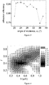
- the diffraction efficiency for the contact grating with a lattice constant of d 2 of the hybrid generation arrangement constructed in an optimal manner regarding the optical imaging is illustrated in Figure 3 as a function of the incidence angle ⁇ 2 of the pump beam having a pre-tilted pulse front, without the use of RIML and with the LN contact grating cooled to 100K.
- the diffraction efficiency is shown as a function of the incidence angle ⁇ 2 with a lattice constant chosen for each value that ensures the required extent of pulse front tilt in the LN crystal, and with an equal extent of pre-tilting (65° in air).
- Table 2 summarizes the parameters of three different generation arrangements based on the tilted-pulse-front technique. That is, the characteristic parameters of the hybrid arrangement, the conventional generation arrangement optimized as described in the scientific publication of Fülöp J. et al. entitled “Design of high-energy terahertz sources based on optical rectification” [Optics Express, 2011, vol. 18, issue 12, pages 12311-12327 ], and the contact grating generation arrangement optimized as described in the scientific publication of Ollmann Z. et al. entitled “Design of a contact grating setup for mJ-energy THz pulse generation by optical rectification” [Applied Physics B, 2012, vol. 108, issue 4, pages 821-826 ]. Table 2.
- Figure 4 illustrates the diffraction efficiency as a function of the filling factor f and the profile depth h on the entry plane of the LN crystal in the case of a square grating having binary grating profile in harmony with the parameters in the 'hybrid arrangement' line of Table 2.
- diffraction efficiency above 85% may be achieved, and the range having similarly high diffraction efficiency is relatively wide; this provides a high tolerance regarding the machining (line formation) on the entry plane of the LN crystal.
- the profile depth h corresponding to the high efficiency range is smaller than the lattice constant d 2 , and the filling factor f is close to 50%, which values are also advantageous regarding the machining.
- the lattice constant of 0.639 ⁇ m (line-density of 1564/mm) of the grating to be formed in the LN crystal is also under the about 2000/mm threshold value, which also guarantees that the contact grating is practically realizable.
- the efficiency of THz beam generation is significantly affected by the pulse length distortion of the pump pulse due to imaging errors.
- Figure 5 illustrates this for an optimized conventional arrangement and a hybrid generation arrangement.
- the local pulse length change ( ⁇ ) caused by the imaging errors is shown in the plane of angular dispersion transversally (y) along the beam diameter.
- the two curves clearly show the advantage of the hybrid arrangement according to the invention versus the conventional one, as the extent of pulse length expansion is significantly lower in the case of the hybrid arrangement. It can also be seen from the curves that for the hybrid arrangement, the pulse length remains below 500 fs everywhere in the beam even for beam diameters exceeding 10 mm, while for the conventional arrangement, the pump beam becomes longer than 1000 fs at the edge of the beam.
- a further advantage of the hybrid generation arrangement is that in the case of LN crystal, the exit plane of the THz generating prism forms an angle with the entry plane that is significantly smaller ( ⁇ 30°) than in the case of a conventional solution ( ⁇ 63°). This is advantageous for the intensity distribution of the THz beam.
- a further advantage is that THz beam generation of high efficiency is possible in a generation arrangement which does not contain/require refractive index matching liquid.
Landscapes
- Physics & Mathematics (AREA)
- Nonlinear Science (AREA)
- Optics & Photonics (AREA)
- General Physics & Mathematics (AREA)
- Chemical & Material Sciences (AREA)
- Crystallography & Structural Chemistry (AREA)
- Electromagnetism (AREA)
- Engineering & Computer Science (AREA)
- Plasma & Fusion (AREA)
- Optical Modulation, Optical Deflection, Nonlinear Optics, Optical Demodulation, Optical Logic Elements (AREA)
Description
- The present invention relates to a method for generating terahertz (THz) radiation and a THz radiation source. In particular, the object of the present invention is a method and arrangement (the radiation source itself) to generate THz radiation via optical rectification in a nonlinear optical medium. In particular, the present invention is closely related to high energy THz radiation sources with tilted pulse front and a method to generate high energy THz radiation based on the tilted pulse front technique.
- The use and thus the generation of THz pulses (particularly consisting of only a few optical cycles) having high energy and high field strength comes more and more into the front nowadays especially in the medical, security, nonlinear spectroscopy, particle manipulation and lots of other fields. Here, and from now on, the term 'THz radiation' refers to optical radiation in the far infrared domain with its main spectrum being in the frequency range of 0.1-10 THz.
- Optical rectification of laser pulses having femtosecond (fs) pulse length in a nonlinear medium (e.g. in crystals having nonlinear optical properties) can be considered rather efficient methods for generating THz pulses having picosecond (ps) pulse length. Typically, ultrashort THz pulses (i.e. having a pulse length of several ps) may be generated by pump pulses in the visible or near infrared domain having pulse lengths of several hundred fs. As it is known, well defined phase matching conditions have to be satisfied for the occurrence of nonlinear phenomena, which in this case means a so-called velocity matching: the group velocity vp;cs of the pump pulse has to be equal to the phase velocity vTHz;f of the generated THz pulse. If these velocities are close to each other in the medium having nonlinear optical properties, i.e. the group refractive index of the nonlinear medium at the frequency of the pumping does not differ by too much from the phase refractive index in the THz domain, this condition can be satisfied relatively easily - as it is known to a person skilled in the art. However, the efficiency of THz radiation generation is greatly affected by the second order nonlinear optical coefficient of the nonlinear medium. There are materials, whose nonlinear optical coefficient has a preferably high value, but due to the high value of the aforementioned refractive index difference, the velocity-matched THz radiation generation is an unsolvable technical problem. Lithium niobate LiNbO3 (LN) is such a material with extraordinary high optical nonlinearity, in which the ratio of said refractive indices is greater than two.
- In such cases, preferably the so-called tilted-pulse-front technique may be used (see the scientific publication of Hebling J. et al. entitled "Velocity matching by pulse front tilting for large-area THz-pulse generation" [Optics Express, 2002, vol. 10, issue 21, pages 1161-1166]. This is based on the fact that generation of THz radiation takes place by means of a light pulse in which the pulse front (intensity front) forms a required angle (γ) with the wave front (phase front). As the generated THz beam propagates perpendicularly to the tilted pulse front, as a consequence of the phase matching condition, the projection of the group velocity vector of pumping onto the direction of the propagation direction of the THz radiation has to be equal to the phase velocity of the THz beam, i.e. the

- In a widespread technical implementation of the tilted-pulse-front technique, the pulse front tilt of a beam of the pump source is induced by diffracting said beam on an (mostly reflective) optical grating. Then the diffracted beam is guided through an optical lens or telescope (i.e. an imaging optics) directly into the nonlinear crystal (e.g. LN) to generate THz radiation in such a manner, that the image of the beam spot appearing on the surface of the optical grating is imaged into the crystal by the lens or telescope, wherein the desired THz radiation is generated as a result of the nonlinear phenomena. The pump pulse is guided onto the entry plane of the crystal mostly/preferably perpendicularly, thus in order to minimize reflection losses, the exit plane and the entry plane of the crystal have to be oriented at an angle γ relative to each other, i.e. the optical medium substantially forms an optical prism to ensure a perpendicular exit of the THz beam from the crystal. The magnitude of angle γ is material specific, thus its value is explicitly determined based on the crystal to be used. That is, in particular, in the case of LN said value is γ ≈ 63°.
- Nowadays, the tilted-pulse-front technique substantially is a routine method for generating THz radiation, in the last decade, using LN crystal, an increase of about seven magnitudes has been achieved with this technique in the energy of quasi single cycle THz pulses. The pulse front tilting by a diffraction element, and the transformation on imaging optics disposed after the dispersive element is discussed in numerous publications in the literature, for example - without completeness - the work of H. Hirori et al. entitled "Single-cycle terahertz pulses with amplitudes exceeding 1 MV/cm generated by optical rectification in LiNbO(3)" [see Applied Physics Letters, 2011, vol. 98, issue 9, page 3] that uses LN crystal as nonlinear optical medium or the publication of Blanchard et al. entitled "Terahertz pulse generation from bulk GaAs by a tilted-pulse-front excitation at 1.8 µm" [see Applied Physics Letters, 2014, vol. 105, page 241106], which uses gallium-arsenide crystal with plane parallel structure as nonlinear optical medium. A method for THz radiation generation by the tilted-pulse-front technique is further discussed in the European patent no.
EP-2,354,841 B1 , which discusses a method and device for THz radiation generation based on optical rectification, carried out by a tilted-pulse-front pump pulse, wherein said pump pulse is guided onto a transmissive or reflective grating where it is diffracted and thus its pulse front is tilted, then this pulse is imaged into a suitable nonlinear crystal, e.g. LN crystal, by an imaging optical system. - The imaging errors (e.g. different types of aberrations) of the imaging optics in the case of tilted-pulse-front THz generation arrangements having imaging optics cause distortion of the pump pulses in the nonlinear medium, namely local pulse length widening, which effect increases by the distance from the optical axis. As one of the important factors determining the efficiency of THz radiation generation is the pulse length of the pump pulse, these imaging errors cause a significant efficiency decrease. Due to the limited optical damage threshold of materials, the increase of the pump energy necessarily leads to the increase of the beam diameter (cross section?). However in the case of large diameter (i.e. wide) pump beams said pulse length widening causes significant decrease in the efficiency of THz radiation generation.
- Thus, the imaging optics is disadvantageous from the point of view of tilted pulse front THz generation arrangements comprising it, because it decreases the efficiency of THz radiation generation at large pump energies, and thus it significantly limits the feasibility of large energy THz radiation generation carried out by the tilted-pulse-front technique, and thus the achievable energy of THz radiation generated thereby.
- In recent years, study of imaging optics forming substantial parts of the tilted-pulse-front technique has been the object of numerous studies. For example the publication of J. Fülöp et al. entitled "Design of high-energy terahertz sources based on optical rectification" [see Optics Express, 2010, vol. 18, ] discusses a THz radiation generation arrangement, which is based on the combination of an optical grating (as spectral dispersive element) and a special imaging optics (a collecting lens). The essence of the arrangement is that the pulse front tilt satisfying the velocity matching condition required for coupling in the pump pulse into the nonlinear optical medium that is required for the THz radiation generation is achieved in a single step on an optical grating disposed in the propagation path of the pump pulse, i.e. in the light path, before the imaging optics.
- Said scientific publication also provides a detailed guide for the optimal construction of an optical imaging arrangement implemented with the lens. Accordingly efficient THz radiation generation requires that (i) the pulse front tilt in the crystal is as large as required by the velocity matching condition (e.g. about 63° in the case of LN), and (ii) in order to minimize the effect of imaging errors on the efficiency of THz radiation generation, the pump pulse length along the tilted pulse front in the nonlinear optical medium is as close to the transformation-limited value as possible. In order to satisfy this, the image of the beam spot appearing on the optical grating created in the crystal has to contact the tilted-pulse-front surface along the optical axis.
- The imaging errors unique for imaging optics and thus the drawbacks of using imagining optics however not even this work has been able to rule out completely.
- A further widespread method for THz radiation generation is - besides the tilted-pulse-front THz generation arrangements having imaging optics - the so called contact grating arrangement (see the scientific publication of L. Pálfalvi et al. entitled "Novel setups for extremely high power single-cycle terahertz pulse generation by optical rectification" [Applied Physics Letters, 2008, vol. 92, issue 1, pages 171107-171109]). A characteristic feature of these is that pulse front tilt of the pump beam is achieved on a single optical element having angular-dispersion-inducing property formed in the surface of the nonlinear optical medium (e.g. by etching), preferably by a single step of diffraction on a single transmissive optical grating. The period (or line-density) of the optical grating that is necessary for this is determined by the material of the nonlinear crystal and the emission wavelength of the pump source. The primary parameters limiting the size of the pump beam in the contact grating arrangement is the damage threshold of the material and the dimensional constraints of the crystal growing, therefore particularly large energy pumping (i.e. by a wide beam) can be achieved.
- In recent years, THz radiation generation by the contact-grating arrangement has become also a subject of numerous scientific publications, thus the optimal design and practical implementations of suitable contact gratings are discussed relatively widely. As a result of said studies, further factors limiting the use of the contact grating arrangement became apparent.
- For example, the work of A. Nagashima et al. entitled "Design of Rectangular Transmission Gratings Fabricated in LiNbO3 for High-Power Terahertz-Wave Generation" [see Japanese Journal of Applied Physics, 2010, vol. 49, page 122504-1] and the publication of A. Nagashima et al. entitled "Erratum: Design of Rectangular Transmission Gratings Fabricated in LiNbO3 for High-Power Terahertz-Wave Generation" [see Japanese Journal of Applied Physics, 2012, vol. 51, page 119201-1] extensively study the theoretical modeling of the contact grating to be formed in the surface of a LN crystal. Taking a binary grating profile as a basis (see
Figure 1 ) the diffraction efficiency of the contact grating was optimized as a function of the lattice constant (d2 ), the filling factor (f=w/d, here w is the profile width) and the profile depth (h). They came to the conclusion that it was practical to use an intermediate material, in particular, fused silica on the air/LN boundary surface in order to improve the efficiency of only 20% achievable with optimal lattice constant (d2 =0.42 µm, line-density of 2380/mm) in the case of an air/LN contact grating setup. According to their theoretical calculations, a diffraction efficiency of 90% may be achieved with the air/fused silica/LN contact grating structure at the optimal lattice constant (d2 =0.36 µm, line-density of 2777/mm). As the problem of applying silica on the submicron sized structure of the LN surface is not solved nowadays, the technical/practical implementation of the theoretically obtained structure would be quite difficult, if possible at all. - A possible solution for this technical problem is using a refractive index matching liquid (RIML) on the air/LN crystal boundary surface, as suggested in the work of Ollmann Z. et al. entitled "Design of a contact grating setup for mJ-energy THz pulse generation by optical rectification" [see Applied Physics B, 2012, vol. 108, ]. This publication discusses the details of coupling in and out of an LN crystal in a contact grating arrangement in the case of numerous possible RIML materials, and the effects of dispersion during propagation through the crystal; in particular, a diffraction efficiency of 98% is predicted for a RIML material with a refractive index equivalent to that of e.g. a type BK7 glass comprising a grating with a lattice constant of 0.35 µm (i.e. line-density of 2874/mm).
- However, studies regarding the formation of contact-gratings in the surface of nonlinear optical media, and thus particularly of LN crystals, show that the crystal surfaces can only be machined only up to a certain (material dependent) line-density limit. In particular, if the line-density is above this limit, the profile of the created grating becomes blurred. This causes the actual diffraction efficiency of the grating in typical pump beam wavelengths to fall far below the theoretical predictions, because the diffraction efficiency of the grating is very sensitive to the formed grating profile. According to our studies, this limit in the cases of e.g. LN or LiTaO3 (lithium tantalate) is about 2000/mm for pump beam wavelength of 1030 nm. I.e. according to our experimental results, the grating geometries with line densities of 2500-3000 1/mm predicting the promising efficiencies described in the aforementioned publications cannot be practically implemented to achieve the theoretically predicted efficiencies with the methods available nowadays (e.g. reactive ion etching, lithographic methods, ablation techniques, etc.).
- Accordingly the THz radiation generation solutions based on a contact grating are not sufficient for high energy THz radiation generation in themselves, because machining difficulties prevent the formation of good quality grating profiles in cases wherein formation of a grating with high line-density would be necessary.
- It should be here further noted, that tilted-pulse-front THz generation arrangements comprising imaging optics and contact grating based THz generation arrangements have been extensively studied and compared with each other in literature as independent solutions providing alternative generating schemes mutually excluding each other. In particular, the publication of M. Kunitski et al. entitled "Optimization of single-cycle terahertz generation in LiNbO3 for sub-50 femtosecond pump pulses" [see Optics Express, 2013, vol. 21, ] compare LN crystal based arrangements for THz radiation generation by tilted pulse front pump pulses. The paper discusses four conventional arrangements with optical grating and imaging optics (with lens, refracting telescope, mirror, reflecting telescope), whose efficacy is compared with each other and with a contact grating arrangement on the basis of model calculations. Optical errors of different optical imaging systems are studied and described in great detail. Based on the result of the comparison, a ranking is established among said arrangements, wherein the contact grating arrangement and the conventional arrangement are considered to be mutually exclusive solutions.
- By comparing the advantages and disadvantages of tilted-pulse-front techniques, namely the arrangements comprising imaging optics (from now on, conventional arrangements) and the contact grating based arrangements, we have came to the conclusion, that grating profiles obtained by manufacturing methods available nowadays can be made suitable to provide diffraction efficiencies as predicted by theoretical calculations (but only at significantly greater line densities). According to our studies, this requires the tilting of the pulse front of the pump pulses to the extent required by the velocity matching condition in more than one step, as a series of partial pulse front tilts or, putting this another way, as a sum of pulse front tilts created separately from each other. That is, the pump pulses have to be subjected to pulse front tilting (pre-tilting) before their incidence on the contact grating, which may be carried out by e.g. a combination of an angular-dispersive element and an imaging optics used e.g. in conventional techniques. According to our studies, the pulse front tilt of pump pulses required to satisfy the velocity matching condition is preferably achieved by at least two optical elements with angular-dispersion-inducing property spatially separated from each other (in the light path) instead of a single optical element with angular-dispersion-inducing properties.
- In light of the aforementioned, an object of the present invention is to provide a hybrid tilted-pulse-front THz generation arrangement by combining the tilted-pulse-front THz generation arrangement comprising imaging optics and the THz generation arrangement with a contact grating, which significantly reduces or eliminates the disadvantages of the aforementioned prior art solutions.
- A further object of the present invention is to provide a method and radiation source for generating high energy THz radiation, i.e. in the mJ domain, particularly with using materials characterized by high nonlinear optical coefficient, such as LN, as nonlinear optical medium.
JP 2014 044 365 claim 6. - A yet further object of the present invention is to provide a method and radiation source for generating high energy THz radiation, wherein the distortion of the beam profile of the generated THz radiation may also be moderated.
- The object of providing a method for generating THz radiation is achieved by the method according to claim 1. Further preferred embodiments of the method according to the invention are set out in
claims 2 to 5. The object of providing a terahertz radiation source is achieved by the radiation source according toclaim 6. Preferred embodiments of the terahertz radiation source according to the invention are set out in claims 7 to 13. - In the case of a tilted-pulse-front hybrid generation arrangement comprising both an imaging optics and a contact grating arrangement, and in the case of a high-energy THz radiation source according to the arrangement:
- on the one hand, contact grating can be used for materials exploited in THz radiation generation with nonlinear optical properties (and thus for LN), wherein achieving high diffraction efficiency would require line densities that would cause technical problems and would not technologically be implementable,
- on the other hand, as the extent of pre-tilting of the pulse front may be much less than what would be necessary in an arrangement based only on the combination of an optical grating and an imaging optics, the influence of the imaging errors on the local pulse length is significantly reduced that is highly beneficial to the efficiency of THz radiation generation.
- In particular, in a preferred embodiment of the hybrid generation arrangement according to the invention, the grating formed in the surface of the material having nonlinear optical properties has significantly lower line-density than in arrangements comprising only a contact grating, thus the (contact)grating required for pump pulses to be coupled into the material having nonlinear optical properties may be formed as a high quality optical grating regarding its fine structure.
- The hybrid generation arrangement according to the invention has the further advantage that to achieve a high diffraction efficiency, no use of a refractive index matching liquid is required.
- A further advantage of the hybrid generation arrangement according to the invention is that dividing the pulse front tilt of the pump pulses necessary for satisfying the velocity matching condition to two or more separate steps results in the reduction of the angle formed between the entry- and exit plane of the optical medium used for THz radiation generation, which is especially advantageous in the case of THz beams having large transversal dimensions, because this may reduce distortion of the exiting beam profile due to the smaller dispersion of the beam parts closer to the edges, therefore it is possible to improve the quality of the THz beam.
- Arrangements having imaging optics and arrangements having a contact grating, and the advantages/disadvantages thereof are known from the literature dealing with the development of THz radiation sources. The combination of the two methods and the creation of a single so-called hybrid arrangement having both imaging optics and contact grating is not known from the literature and there is not even a hint thereto - as far as we know -, moreover, as mentioned previously, these two solutions are considered and used only as alternatives of each other in the art.
- In what follows, the invention is described in detail with reference to the accompanying drawings, wherein
-
Figure 1 illustrates - in an enlarged view - the characteristic parameters of the grating profile of a contact grating with a binary grating profile that represents a preferred embodiment of the contact grating that can be used as the optical element with angular-dispersion-inducing property in the hybrid generation arrangement according to the invention; -
Figure 2 shows schematically a preferred embodiment of the THz radiation source implementing a hybrid generation arrangement according to the invention with an angular-dispersive optical element formed by a transmission optical grating disposed in the light path before (i.e. upstream of) the imaging optics and a contact grating arranged after (i.e. downstream of) the imaging optics resulting in pulse front tilt of the pump beam is more than one separate steps; -
Figure 3 shows the diffraction efficiency of a contact grating used in the hybrid generation arrangement according to the invention formed in the surface, in particular, of an LN crystal with a grating profile as illustrated inFigure 1 as a function of the incidence angle (α2) of the pump beam having a tilted pulse front, with the geometric parameters summarized in Table 2; -
Figure 4 shows the diffraction efficiency of a contact grating formed in the surface, in particular, of an LN crystal with a grating profile as illustrated inFigure 1 used in the hybrid generation arrangement according to the invention as a function of the filling factor (f=w/d2) and the profile depth (h); and -
Figure 5 shows changes in pulse length (τ) in a transversal direction (y) perpendicular to the propagation of the pump beam due to imaging errors of a hybrid generation arrangement according to the invention implemented with a contact grating etched into the surface of, in particular, an LN crystal and of a corresponding conventional generation arrangement. - The so-called hybrid tilted-pulse-front THz beam generation arrangement according to the invention, and a preferred embodiment of the
THz radiation source 100 for generating THz radiation are illustrated inFigure 2 . Theradiation source 100 comprises apump source 10 for providing apump beam 12, and anoptical element 50 having nonlinear optical properties for generatingTHz radiation 60. Theoptical element 50 has anexit plane 52 and an opposingentry plane 51, which forms a predetermined angle with theexit plane 52; therefore theoptical element 50 is preferably formed as a prism or optical wedge. TheTHz radiation 60 is generated as a result of the nonlinear optical interaction of the material of theoptical element 50 and thepump beam 12, preferably by optical rectification, in the volume of theoptical element 50 substantially at a distance L3 from theentry plane 51, then it leaves theoptical element 50 through itsexit plane 52 and then it may be subjected to further use. A contact grating 40 characterized by predetermined geometrical parameters is arranged on theentry plane 51 in perfect optical coupling with saidentry plane 51 or formed in theentry plane 51. In practice, the contact grating 40 is formed by an optical grating having an optical axis O2 and a lattice constant d2, wherein the optical axis O2 is substantially perpendicular to theentry plane 51. - The
pump source 10 and the optical element 50 - as an initial element and a final element - together define a light path extending between the emission point of thepump source 10 and theentry plane 51. Theradiation source 100 comprises in said light path, in the propagation direction of thepump beam 12, i.e. toward theentry plane 51 respectively a first optical element having angular dispersion inducing property, i.e. an angular-dispersiveoptical element 20 and animaging optics 30 in a predetermined geometrical arrangement; theoptical element 20 and theimaging optics 30 are located at a mutual distance L1 along the light path, while theimaging optics 30 and the contact grating 40 are arranged at a mutual distance L2. Determining the geometric parameters comprising the distances L1, L2 and L3 is described in detail in the following. - The
pump source 10 is preferably a laser source suitable to produce laser pulses - the pump beam 12 - in the visible, near- or mid-infrared domain with a pulse length of several hundred fs, e.g. a diode pumped Yb laser with a central emission wavelength of 1030 nm. However, different lasers may also be used aspump source 10. - The
optical element 20 is formed as an optical element inducing the dispersion of thepump beam 12 incident thereon and transmitted therethrough, and thus changing the tilt of the initial pulse front 15 (characterized by preferably zero tilt) of thepump beam 12 by a predetermined amount. The angular-dispersiveoptical element 20 may be provided by a diffraction based optical element (preferably optical grating) or by a refraction based optical element (preferably a prism/prisms) or by a combination thereof (e.g. a prism combined with a diffraction grating, i.e. a so-called grism). In the embodiment of theradiation source 100 illustrated inFigure 2 , theoptical element 20 is preferably a transmissive grating having an optical axis O1 and a lattice constant d1, however - as it is obvious to a person skilled in the art - it may also be provided by other angular-dispersive optical elements, e.g. a reflective grating, prism, etc. The advantage of constructing it as a transmission grating is the relatively high separation of theincident pump pulse 12 and thebeam 22 diffracted e.g. in the first order. In this case, thepump beam 12 incident in an angle α1 relative to the optical axis O1 on theoptical element 20 provided in the form of a transmission grating is diffracted in an angle β1 and transmitted in the light path as thebeam 22, wherein thepulse front 25 of thebeam 22 has a certain extent of tilt; the extent of tilt is explicitly determined by the wavelength λ of thepump beam 12, the lattice constant d1 and the angle of incidence α1 through the following relations:


- As it is known to a person skilled in the art, the tilt of the
pulse front 25 may be derived through similar relations when different types of angular-dispersiveoptical elements 20 are used. - The
imaging optics 30 may be provided by any imaging optics known from the field of conventional tilted-pulse-front THz generation arrangements having imaging optics. Thus, for example theimaging optics 30 may be provided in the form of a lens, refracting telescope, mirrors, reflecting telescope, or a concave mirror or in the case of a reflecting telescope, the telescope having concave mirrors may be formed by both spherical and cylindrical mirrors. Any of said optical elements used for theimaging optics 30, may be formed with spherical shape, cylindrical shape or a shape with minimized imaging error ('bestform'). In the embodiment of theradiation source 100 illustrated inFigure 2 , theimaging optics 30 is provided in the form of a focusing lens having a certain diameter and a focal length fL (e.g. fL=200mm). Theimaging optics 30 images the (in this case) diffractedbeam 22 having apre-tilted pulse front 25 into theoptical element 50 as abeam 32 having apulse front 35. In particular, in this embodiment of theradiation source 100, thebeam 22 is guided by the imaging optics 30 - in the form ofbeam 32 at an angle α2 relative to the optical axis O2 - to a further optical element with angular-dispersion-inducing property, in particular, to a contact grating 40 and after being diffracted it is introduced into the volume of theoptical element 50 in the form ofbeam 42. Thepulse front 45 of thebeam 42 is tilted to the extent required by the phase matching condition. The tilted-pulse-front beam 42 propagates in theoptical element 50 at angle β2 to the normal of the crystal lattice. The phase fronts of the generatedTHz radiation 60 are parallel to the tiltedpulse front 45, thus the propagation direction of theTHz radiation 60 is necessarily perpendicular to these planes. - The contact grating 40 is preferably provided as an optical grating having a grating profile illustrated in
Figure 1 i.e. a so-called binary grating profile. It is known to a person skilled in the art, that the contact grating may be implemented with different grating profiles (e.g. sinusoidal, sawtooth etc.), further preferred exemplary grating profiles may be known from the scientific publication of Ollmann Z. et al. entitled "Design of a high-energy terahertz pulse source based on ZnTe contact grating" [Optics Communication, 2014, issue 315, pages 159-163]. - The
optical element 50 is made of a material having an outstandingly high nonlinear optical coefficient, practically at least 1 pm/V, and having different refractive indices in the terahertz and the visible domain, preferably LN or lithium-tantalate, preferably with a crystal-axis orientation that facilitates the occurrence of nonlinear optical phenomena, thus aiding e.g. the occurrence of optical rectification and thus the generation of THz radiation. Moreover, in order to minimize reflection losses, theexit plane 52 of theoptical element 50 is formed to emit theTHz radiation 60 generated in theoptical element 50 through theexit plane 52 of theoptical element 50 perpendicularly. - As mentioned previously, the geometric parameters (see
Figure 2 ) characterizing the geometric arrangement of the elements forming parts of theradiation source 100 may be obtained by optimization. The optimization is based on the following conditions of efficient THz radiation generation: - the summed tilt of the
pulse front 45 of thebeam 42 satisfies the velocity matching condition; - in order to minimize the effect of the imaging errors on the efficiency of THz beam generation, the pulse length of the pump pulse along the
pulse front 45 inside theoptical element 50 is as close to the transformation-limited value as possible, i.e. the image of the beam spot of thebeam 22 appearing on the angular-dispersiveoptical element 20 in theoptical element 50 contacts the tilted-pulse-front surface along the optical axis. - Without showing detailed mathematical deductions (which are obvious to a person skilled in the art), the general equations for the selection of the angular-dispersive
optical element 20 and theimaging optics 30, and for determining the geometry of theradiation source 100 after fixing the grating profile of the contact grating 40 are summarized in the following. Accordingly:


Table 1: description of parameters used in equations (1) to (10). λ central wavelength of the pump source 10α1 angle of incidence at the optical grating forming the angular-dispersive optical element 20 fL focal length of the lens forming the imaging optics 30β1 diffraction angle at the optical grating forming the angular-dispersive optical element 20γ required extent of pulse front tilt inside the optical element 50α2 angle of incidence at the contact grating 40 γ0 extent of pulse front pre-tilting (initial/partial tilt of the pulse front) β2 diffraction angle at the contact grating 40 n refractive index of the optical element 50 L1 relative distance of the angular-dispersive optical element 20 and the imaging optics 30ng group refractive index of the optical element 50 L2 distance of the imaging optics 30 and the contact grating 40d1 lattice constant of the optical grating forming the angular-dispersive element 20 L3 distance of intensive THz radiation generation inside the optical element 50 from theentry plane 51 thereof - Assuming real physical parameters, the results of (analytic) calculations carried out on the basis of a system of equations comprising the aforementioned equations (4) to (9) determine explicitly the geometric parameters of the hybrid generation arrangement according to the invention (i.e. of the radiation source 100).
- Parameters λ, f L, γ, n, ng , d 1 , L 3 are determined and/or chosen and/or preset by the user through the selection of the pump source and/or the material of the nonlinear optical medium to be used for the THz radiation generation.
- The extent of pre-tilting of the pulse front of the pump beam 10 (i.e. the first part of pulse front tilting) is selected so that the tangents of the angles characterizing the subsequent (two) steps of inducing pulse front tilts are about the same, i.e.

- It is hereby noted, that the energy of the generated THz pulse is primarily determined (when using - among others - a pump pulse with a given transformation-limited pulse length) by the changes in pulse length originating from the imaging errors of the
imaging optics 30 and occurring in theoptical element 50, and the diffraction efficiency on the contact grating 40 formed in theentry plane 52 of theoptical element 50. Accordingly, as the result of the efficiency-optimization carried out for the contact grating 40, the parameters α2, β 2 , d 2 become fixed. - The remaining (free) parameters, i.e. α 1, β 1, L 1 , L 2 characterize the geometric relations of the hybrid THz generation arrangement according to the invention.
- The tilted-pulse-front hybrid generation arrangement according to the invention is described in detail in the following with the exemplary use of LN crystal as the nonlinear optical medium. The use of LN crystal may be considered special, because this material has outstanding nonlinear properties, but it can only be machined without the deterioration of the profile quality of the grating to be formed in its surface for the widely used (about 1030 nm) pump beam wavelength to a line-density of at most about 2000/mm, therefore the use of the hybrid generation arrangement according to the invention is particularly advantageous in its case. However, the method - with the necessary modifications obvious to a person skilled in the art - may naturally be used in the case of any other material, wherein tilted-pulse-front pumping is required and implementing a solution with merely a contact grating is problematic.
- In this case, the grating profile of the contact grating is the same as the binary grating profile shown in
Figure 1 , a transmissive optical grating is used as the angular-dispersive optical element, and the imaging optics is formed in this case by a (preferably focusing) lens. The extent of pulse front tilt induced by the transmissive optical grating may be simply obtained on the basis of the aforementioned equations (1) to (3) and (10). - In order to ensure efficient THz beam generation, the aforementioned conditions are satisfied, i.e.
- the summed pulse front tilt of the pump beam satisfies the velocity matching condition, i.e. it is about 63° in the case of LN;
- in order to minimize the effect of the imaging errors on the efficiency of THz beam generation, the pulse length of the pumping along the pulse front in LN crystal is as close to the transformation-limited value as possible, i.e. practically the image of the beam spot appearing on the transmissive optical grating having lattice constant d1 in the crystal is in contact with the tilted-pulse-front surface along the optical axis.
- Under these conditions, the geometric parameters obtained by analytic calculations for LN crystal through the aforementioned equations (4) to (9) may be explicitly derived after setting the values of the parameters to be fixed (LN crystal, 1030 nm pump wavelength, etc.)
- Accordingly, the diffraction efficiency for the contact grating with a lattice constant of d2 of the hybrid generation arrangement constructed in an optimal manner regarding the optical imaging is illustrated in
Figure 3 as a function of the incidence angle α2 of the pump beam having a pre-tilted pulse front, without the use of RIML and with the LN contact grating cooled to 100K. The diffraction efficiency is shown as a function of the incidence angle α2 with a lattice constant chosen for each value that ensures the required extent of pulse front tilt in the LN crystal, and with an equal extent of pre-tilting (65° in air). According to the figure, the diffraction efficiency exceeds 85% in the range between 21° and 26°, the angle of incidence corresponding to the flat maximum is α 2 = 24°. From now on, the hybrid generation arrangement with the geometry corresponding to this point is considered optimal and discussed further. - For comparison purposes, Table 2 below summarizes the parameters of three different generation arrangements based on the tilted-pulse-front technique. That is, the characteristic parameters of the hybrid arrangement, the conventional generation arrangement optimized as described in the scientific publication of Fülöp J. et al. entitled "Design of high-energy terahertz sources based on optical rectification" [Optics Express, 2011, vol. 18, ], and the contact grating generation arrangement optimized as described in the scientific publication of Ollmann Z. et al. entitled "Design of a contact grating setup for mJ-energy THz pulse generation by optical rectification" [Applied Physics B, 2012, vol. 108, ].
Table 2. Characteristic geometric parameters for different types of generation arrangements in the case of using an LN crystal, assuming an optimal incidence angle α2. generation arrangement pump wavelength pump pulse length 1/d 1 1/d 2 lens f L α 1 α 2 β 2 hybrid 1030 nm 200 fs 1400/mm 1563/mm 200mm 46° 24° 34° conventional 1030 nm 200 fs 1400/mm - 200mm 37° - - contact grating 1030 nm 200 fs - 2874/mm - - 70° 46° - At a given lattice constant, the diffraction efficiency depends on the parameters characterizing the structure of the grating profile; in the case of the selected square grating having binary grating profile these are the filling factor f = w/d2 and the profile depth h (see also
Figure 1 ) -
Figure 4 illustrates the diffraction efficiency as a function of the filling factor f and the profile depth h on the entry plane of the LN crystal in the case of a square grating having binary grating profile in harmony with the parameters in the 'hybrid arrangement' line of Table 2. As shown, diffraction efficiency above 85% may be achieved, and the range having similarly high diffraction efficiency is relatively wide; this provides a high tolerance regarding the machining (line formation) on the entry plane of the LN crystal. The profile depth h corresponding to the high efficiency range is smaller than the lattice constant d2, and the filling factor f is close to 50%, which values are also advantageous regarding the machining. Moreover, the lattice constant of 0.639 µm (line-density of 1564/mm) of the grating to be formed in the LN crystal is also under the about 2000/mm threshold value, which also guarantees that the contact grating is practically realizable. - According to the aforementioned, the efficiency of THz beam generation is significantly affected by the pulse length distortion of the pump pulse due to imaging errors.
Figure 5 illustrates this for an optimized conventional arrangement and a hybrid generation arrangement. The local pulse length change (τ) caused by the imaging errors is shown in the plane of angular dispersion transversally (y) along the beam diameter. The two curves clearly show the advantage of the hybrid arrangement according to the invention versus the conventional one, as the extent of pulse length expansion is significantly lower in the case of the hybrid arrangement. It can also be seen from the curves that for the hybrid arrangement, the pulse length remains below 500 fs everywhere in the beam even for beam diameters exceeding 10 mm, while for the conventional arrangement, the pump beam becomes longer than 1000 fs at the edge of the beam. - Due to inducing the tilt of the pulse front is carried out in two different steps, creating high quality grating profile with the lower line-density (at most 2000/mm) that can be used in the LN crystal does not cause a manufacturing problem. Furthermore the significantly reduced imaging errors due to the use of the hybrid generation arrangement the efficiency of THz beam generation is higher, and the quality and focusability of the generated THz beam is better than what could be obtained by a conventional generation arrangement.
- Besides the more efficient THz beam generation, a further advantage of the hybrid generation arrangement is that in the case of LN crystal, the exit plane of the THz generating prism forms an angle with the entry plane that is significantly smaller (∼30°) than in the case of a conventional solution (∼63°). This is advantageous for the intensity distribution of the THz beam. A further advantage is that THz beam generation of high efficiency is possible in a generation arrangement which does not contain/require refractive index matching liquid.
Claims (13)
- A method to generate terahertz radiation in a nonlinear optical medium, wherein a pump pulse is subjected to pulse front tilting, the thus obtained pump pulse having tilted pulse front is coupled into the nonlinear optical medium and a THz pulse is generated by means of the optical medium in nonlinear optical processes, particularly by means of optical rectification by the pump pulse, the pulse front tilt of the pump pulse required to satisfy a velocity matching condition of v p;cs cos(γ) = v THz;f is induced as a sum of a plurality of partial pulse front tilts of the pump pulse, induced separately in subsequent steps, wherein vp;cs is the group velocity of the pump pulse, vTHz;f is the phase velocity of the THz pulse, and γ is the angle formed between the pulse front and the phase front of said pump pulse, and wherein the sum of the plurality of partial pulse front tilts is divided into a first partial pulse front tilt and further partial pulse front tilts wherein the pump pulse is subjected to the first partial pulse front tilt, characterized in that the further partial pulse front tilts of the pump pulse are induced by guiding the pump pulse having the first partial pulse front tilt with the imaging optics (30) via coupling the pump pulse into the nonlinear optical medium by means of a contact grating (40) being in optical coupling with the nonlinear optical medium or formed on an entry plane of the optical medium.
- The method according to claim 1, characterized in that the first partial pulse front tilt of the pump pulse is induced by guiding the pump pulse onto a first optical element (20) having angular-dispersion-inducing property, and then by guiding the pump beam leaving the first optical element (20) having angular-dispersion-inducing property onto an imaging optics (30).
- The method according to any one of claims 1 to 2, characterized in that the pump pulse is a laser pulse in the visible, near- or mid-infrared domain having a length of at most several hundred femtoseconds.
- The method according to any one of claims 1 to 3, characterized in that the first optical element (20) having angular-dispersion-inducing property is a diffraction based optical element or a refraction based optical element or an optical element that is a combination thereof.
- The method according to any one of claims 1 to 4, characterized in that the imaging optics (30) is an imaging optics as used in per se known tilted-pulse-front THz generation arrangements having imaging optics.
- A terahertz radiation source (100), comprising a pump source (10) for emitting a pump pulse and a nonlinear optical medium for generating THz pulses, wherein the pump source (10) and the nonlinear optical medium define together a light path, said light path being arranged to guide the pump pulse from the pump source (10) to the nonlinear optical medium, and wherein a first optical element (20) having angular-dispersion-inducing property and an imaging optics (30) are arranged in said light path after each other in the propagation direction of the pump pulse, wherein at least one further optical element with angular-dispersion-inducing property is arranged within said light path, said further optical element located after both the first optical element (20) having angular-dispersion-inducing property and the imaging optics (30) in the propagation direction of said pump pulse, characterized in that the at least one further optical element with angular-dispersion-inducing property is a single contact grating (40) arranged at the entry plane (51) of the nonlinear optical medium bordering the light path.
- The radiation source according to claim 6, characterized in that contact grating (40) is formed in the material of the nonlinear optical medium.
- The radiation source according to any one of claims 6 to 7, characterized in that the first optical element (20) having angular-dispersion-inducing property is selected from a group comprising diffraction based optical elements, refraction based optical elements, and optical elements constructed as a combination thereof.
- The radiation source according to claim 8, characterized in that the first optical element (20) having angular-dispersion-inducing property is a transmissive optical grating.
- The radiation source according to any one of claims 6 to 9, characterized in that the imaging optics (30) is selected from the group comprising imaging optics having any one of a lens, a refracting telescope, a mirror, a reflecting telescope, and concave mirrors.
- The radiation source according to any one of claims 6 to 10, characterized in that the nonlinear optical medium is formed by a material having a nonlinear optical coefficient of at least 1 pm/V and different refractive indices in the terahertz and the visible domain.
- The radiation source according to any one of claims 6 to 11, characterized in that the nonlinear optical medium is formed by a lithium niobate (LiNbO3) or a lithium tantalate (LiTaO3) crystal.
- The radiation source according to any one of claims 6 to 12, characterized in that the pump pulse is a laser pulse in the visible, near- or mid-infrared domain having a length of at most several hundred femtoseconds.
Applications Claiming Priority (2)
| Application Number | Priority Date | Filing Date | Title |
|---|---|---|---|
| HU1500448A HU231075B1 (en) | 2015-09-30 | 2015-09-30 | Method for producing terahertz radiation and terahertz radiation source |
| PCT/HU2016/050046 WO2017081501A2 (en) | 2015-09-30 | 2016-09-30 | Method to generate terahertz radiation and terahertz radiation source |
Publications (2)
| Publication Number | Publication Date |
|---|---|
| EP3353600A2 EP3353600A2 (en) | 2018-08-01 |
| EP3353600B1 true EP3353600B1 (en) | 2020-06-10 |
Family
ID=89991941
Family Applications (1)
| Application Number | Title | Priority Date | Filing Date |
|---|---|---|---|
| EP16849920.0A Active EP3353600B1 (en) | 2015-09-30 | 2016-09-30 | Method to generate terahertz radiation and terahertz radiation source |
Country Status (6)
| Country | Link |
|---|---|
| US (1) | US10359687B2 (en) |
| EP (1) | EP3353600B1 (en) |
| JP (1) | JP6997088B2 (en) |
| DK (1) | DK3353600T3 (en) |
| HU (1) | HU231075B1 (en) |
| WO (1) | WO2017081501A2 (en) |
Families Citing this family (7)
| Publication number | Priority date | Publication date | Assignee | Title |
|---|---|---|---|---|
| HU231075B1 (en) | 2015-09-30 | 2020-05-28 | Pécsi Tudományegyetem | Method for producing terahertz radiation and terahertz radiation source |
| HUE056962T2 (en) | 2017-06-25 | 2022-04-28 | Pecsi Tudomanyegyetem | Method and assembly for generating terahertz radiation |
| CN107561816A (en) * | 2017-10-19 | 2018-01-09 | 北京航空航天大学 | A kind of high energy THz wave generation device |
| EP3608712B1 (en) * | 2018-08-06 | 2023-06-07 | Pécsi Tudományegyetem | Method and setup to generate terahertz radiation scalable in energy |
| US11474414B2 (en) | 2018-10-31 | 2022-10-18 | Pécsi Tudományegyetem | Reflection and/or diffraction-based method and setup to generate high-energy terahertz pulses |
| CN111487581B (en) * | 2020-04-20 | 2022-02-11 | 中国人民解放军军事科学院国防科技创新研究院 | Broadband lightning VHF radiation source direction finding method based on rudder vector pattern matching |
| CN111964780B (en) * | 2020-08-10 | 2025-04-15 | 中国工程物理研究院流体物理研究所 | A single-shot terahertz transient spectroscopy system |
Family Cites Families (8)
| Publication number | Priority date | Publication date | Assignee | Title |
|---|---|---|---|---|
| US7272158B1 (en) * | 2005-02-15 | 2007-09-18 | Hrl Laboratories, Llc | Highly efficient waveguide pulsed THz electromagnetic radiation source and group-matched waveguide THz electromagnetic radiation source |
| JP5216544B2 (en) | 2008-11-13 | 2013-06-19 | 浜松ホトニクス株式会社 | Terahertz wave generator |
| JP2010139604A (en) | 2008-12-10 | 2010-06-24 | Aisin Seiki Co Ltd | Electromagnetic wave generation/transmission apparatus |
| JP5642405B2 (en) * | 2010-03-24 | 2014-12-17 | オリンパス株式会社 | Terahertz wave generator |
| JP5967867B2 (en) * | 2010-06-03 | 2016-08-10 | キヤノン株式会社 | Terahertz wave generating element, terahertz wave detecting element, and terahertz time domain spectroscopic device |
| HU229943B1 (en) | 2010-09-22 | 2015-01-28 | Pecsi Tudomanyegyetem | Optical excited thz radiation source based on rectification |
| JP2014044365A (en) * | 2012-08-28 | 2014-03-13 | Olympus Corp | Pulse front inclined optical system and terahertz wave generator |
| HU231075B1 (en) | 2015-09-30 | 2020-05-28 | Pécsi Tudományegyetem | Method for producing terahertz radiation and terahertz radiation source |
-
2015
- 2015-09-30 HU HU1500448A patent/HU231075B1/en unknown
-
2016
- 2016-09-30 DK DK16849920.0T patent/DK3353600T3/en active
- 2016-09-30 JP JP2018536350A patent/JP6997088B2/en active Active
- 2016-09-30 US US15/763,180 patent/US10359687B2/en active Active
- 2016-09-30 EP EP16849920.0A patent/EP3353600B1/en active Active
- 2016-09-30 WO PCT/HU2016/050046 patent/WO2017081501A2/en not_active Ceased
Non-Patent Citations (1)
| Title |
|---|
| None * |
Also Published As
| Publication number | Publication date |
|---|---|
| HU231075B1 (en) | 2020-05-28 |
| US20180292729A1 (en) | 2018-10-11 |
| WO2017081501A3 (en) | 2017-07-13 |
| WO2017081501A2 (en) | 2017-05-18 |
| US10359687B2 (en) | 2019-07-23 |
| EP3353600A2 (en) | 2018-08-01 |
| JP6997088B2 (en) | 2022-02-04 |
| DK3353600T3 (en) | 2020-08-24 |
| HUP1500448A2 (en) | 2017-04-28 |
| JP2018530010A (en) | 2018-10-11 |
Similar Documents
| Publication | Publication Date | Title |
|---|---|---|
| US10359687B2 (en) | Method to generate terahertz radiation and terahertz radiation source | |
| CN101231383B (en) | Light spectrum modulation reshaping device for chirp pulse amplified self-collimation recessed surface | |
| EP2965852A1 (en) | Optical arrangement for laser beam shaping | |
| EP3396447B1 (en) | Method and setup to generate terahertz radiation | |
| EP2944003B1 (en) | System and method for high-intensity ultrashort pulse compression | |
| JP7858701B2 (en) | Methods and mechanisms for generating terahertz radiation that is scalable in terms of energy. | |
| CN113161850A (en) | Laser pulse compressor and compression method | |
| CN115769139A (en) | Device for spectral broadening of laser pulses and laser system | |
| JP7446323B2 (en) | Reflection and/or diffraction-based methods and apparatus for generating high-energy terahertz pulses | |
| Khazanov | Dependence of the focal intensity of a femtosecond laser pulse on the non-flatness of compressor diffraction gratings | |
| Tóth et al. | Performance comparison of lithium-niobate-based extremely high-field single-cycle terahertz sources | |
| US10594106B2 (en) | Symmetric out-of-plane configurations of diffractive gratings and method | |
| Romanov et al. | Configuration model of a grating pair pulse compressor | |
| US20180287327A1 (en) | Ultra-compact optical pulse compressor | |
| WO2025008649A1 (en) | Semiconductor-based high-energy terahertz radiation source | |
| CN118315904A (en) | Laser pulse spectrum widening device and spectrum widening method | |
| EP4109687A1 (en) | Generation of high energy ultrashort laser pulse | |
| WO2017058054A1 (en) | Waveguide laser device | |
| Poutous | Stable continuous-wave operation of Ti: Sapphire lasers in higher-order transverse Hermite-Gaussian modes | |
| Reiten et al. | Wide bandwidth frequency doubling and harmonic generation of Ti: sapphire laser radiation | |
| Cheng et al. | Flat focusing mirrors with two-dimensional chirped photonic crystals | |
| Forbes et al. | Comparison of infrared laser beam shaping by diffractive and refractive methods | |
| Purlys et al. | Spatial filtering of light beams by axisymmetric photonic mictrostructures | |
| Carstens et al. | Thermal Limitations for Power Scaling of Femtosecond Enhancement Cavities |
Legal Events
| Date | Code | Title | Description |
|---|---|---|---|
| STAA | Information on the status of an ep patent application or granted ep patent |
Free format text: STATUS: UNKNOWN |
|
| STAA | Information on the status of an ep patent application or granted ep patent |
Free format text: STATUS: THE INTERNATIONAL PUBLICATION HAS BEEN MADE |
|
| PUAI | Public reference made under article 153(3) epc to a published international application that has entered the european phase |
Free format text: ORIGINAL CODE: 0009012 |
|
| STAA | Information on the status of an ep patent application or granted ep patent |
Free format text: STATUS: REQUEST FOR EXAMINATION WAS MADE |
|
| 17P | Request for examination filed |
Effective date: 20180427 |
|
| AK | Designated contracting states |
Kind code of ref document: A2 Designated state(s): AL AT BE BG CH CY CZ DE DK EE ES FI FR GB GR HR HU IE IS IT LI LT LU LV MC MK MT NL NO PL PT RO RS SE SI SK SM TR |
|
| AX | Request for extension of the european patent |
Extension state: BA ME |
|
| DAV | Request for validation of the european patent (deleted) | ||
| DAX | Request for extension of the european patent (deleted) | ||
| GRAP | Despatch of communication of intention to grant a patent |
Free format text: ORIGINAL CODE: EPIDOSNIGR1 |
|
| STAA | Information on the status of an ep patent application or granted ep patent |
Free format text: STATUS: GRANT OF PATENT IS INTENDED |
|
| INTG | Intention to grant announced |
Effective date: 20191213 |
|
| GRAS | Grant fee paid |
Free format text: ORIGINAL CODE: EPIDOSNIGR3 |
|
| GRAA | (expected) grant |
Free format text: ORIGINAL CODE: 0009210 |
|
| STAA | Information on the status of an ep patent application or granted ep patent |
Free format text: STATUS: THE PATENT HAS BEEN GRANTED |
|
| AK | Designated contracting states |
Kind code of ref document: B1 Designated state(s): AL AT BE BG CH CY CZ DE DK EE ES FI FR GB GR HR HU IE IS IT LI LT LU LV MC MK MT NL NO PL PT RO RS SE SI SK SM TR |
|
| REG | Reference to a national code |
Ref country code: GB Ref legal event code: FG4D |
|
| REG | Reference to a national code |
Ref country code: CH Ref legal event code: EP Ref country code: AT Ref legal event code: REF Ref document number: 1279656 Country of ref document: AT Kind code of ref document: T Effective date: 20200615 |
|
| REG | Reference to a national code |
Ref country code: DE Ref legal event code: R096 Ref document number: 602016038015 Country of ref document: DE |
|
| REG | Reference to a national code |
Ref country code: IE Ref legal event code: FG4D |
|
| REG | Reference to a national code |
Ref country code: DK Ref legal event code: T3 Effective date: 20200821 |
|
| REG | Reference to a national code |
Ref country code: CH Ref legal event code: NV Representative=s name: VALIPAT S.A. C/O BOVARD SA NEUCHATEL, CH |
|
| REG | Reference to a national code |
Ref country code: LT Ref legal event code: MG4D |
|
| PG25 | Lapsed in a contracting state [announced via postgrant information from national office to epo] |
Ref country code: LT Free format text: LAPSE BECAUSE OF FAILURE TO SUBMIT A TRANSLATION OF THE DESCRIPTION OR TO PAY THE FEE WITHIN THE PRESCRIBED TIME-LIMIT Effective date: 20200610 Ref country code: NO Free format text: LAPSE BECAUSE OF FAILURE TO SUBMIT A TRANSLATION OF THE DESCRIPTION OR TO PAY THE FEE WITHIN THE PRESCRIBED TIME-LIMIT Effective date: 20200910 Ref country code: GR Free format text: LAPSE BECAUSE OF FAILURE TO SUBMIT A TRANSLATION OF THE DESCRIPTION OR TO PAY THE FEE WITHIN THE PRESCRIBED TIME-LIMIT Effective date: 20200911 Ref country code: FI Free format text: LAPSE BECAUSE OF FAILURE TO SUBMIT A TRANSLATION OF THE DESCRIPTION OR TO PAY THE FEE WITHIN THE PRESCRIBED TIME-LIMIT Effective date: 20200610 Ref country code: SE Free format text: LAPSE BECAUSE OF FAILURE TO SUBMIT A TRANSLATION OF THE DESCRIPTION OR TO PAY THE FEE WITHIN THE PRESCRIBED TIME-LIMIT Effective date: 20200610 |
|
| REG | Reference to a national code |
Ref country code: NL Ref legal event code: MP Effective date: 20200610 |
|
| PG25 | Lapsed in a contracting state [announced via postgrant information from national office to epo] |
Ref country code: BG Free format text: LAPSE BECAUSE OF FAILURE TO SUBMIT A TRANSLATION OF THE DESCRIPTION OR TO PAY THE FEE WITHIN THE PRESCRIBED TIME-LIMIT Effective date: 20200910 Ref country code: LV Free format text: LAPSE BECAUSE OF FAILURE TO SUBMIT A TRANSLATION OF THE DESCRIPTION OR TO PAY THE FEE WITHIN THE PRESCRIBED TIME-LIMIT Effective date: 20200610 Ref country code: HR Free format text: LAPSE BECAUSE OF FAILURE TO SUBMIT A TRANSLATION OF THE DESCRIPTION OR TO PAY THE FEE WITHIN THE PRESCRIBED TIME-LIMIT Effective date: 20200610 Ref country code: RS Free format text: LAPSE BECAUSE OF FAILURE TO SUBMIT A TRANSLATION OF THE DESCRIPTION OR TO PAY THE FEE WITHIN THE PRESCRIBED TIME-LIMIT Effective date: 20200610 |
|
| REG | Reference to a national code |
Ref country code: AT Ref legal event code: MK05 Ref document number: 1279656 Country of ref document: AT Kind code of ref document: T Effective date: 20200610 |
|
| PG25 | Lapsed in a contracting state [announced via postgrant information from national office to epo] |
Ref country code: AL Free format text: LAPSE BECAUSE OF FAILURE TO SUBMIT A TRANSLATION OF THE DESCRIPTION OR TO PAY THE FEE WITHIN THE PRESCRIBED TIME-LIMIT Effective date: 20200610 Ref country code: NL Free format text: LAPSE BECAUSE OF FAILURE TO SUBMIT A TRANSLATION OF THE DESCRIPTION OR TO PAY THE FEE WITHIN THE PRESCRIBED TIME-LIMIT Effective date: 20200610 |
|
| PG25 | Lapsed in a contracting state [announced via postgrant information from national office to epo] |
Ref country code: EE Free format text: LAPSE BECAUSE OF FAILURE TO SUBMIT A TRANSLATION OF THE DESCRIPTION OR TO PAY THE FEE WITHIN THE PRESCRIBED TIME-LIMIT Effective date: 20200610 Ref country code: AT Free format text: LAPSE BECAUSE OF FAILURE TO SUBMIT A TRANSLATION OF THE DESCRIPTION OR TO PAY THE FEE WITHIN THE PRESCRIBED TIME-LIMIT Effective date: 20200610 Ref country code: SM Free format text: LAPSE BECAUSE OF FAILURE TO SUBMIT A TRANSLATION OF THE DESCRIPTION OR TO PAY THE FEE WITHIN THE PRESCRIBED TIME-LIMIT Effective date: 20200610 Ref country code: ES Free format text: LAPSE BECAUSE OF FAILURE TO SUBMIT A TRANSLATION OF THE DESCRIPTION OR TO PAY THE FEE WITHIN THE PRESCRIBED TIME-LIMIT Effective date: 20200610 Ref country code: RO Free format text: LAPSE BECAUSE OF FAILURE TO SUBMIT A TRANSLATION OF THE DESCRIPTION OR TO PAY THE FEE WITHIN THE PRESCRIBED TIME-LIMIT Effective date: 20200610 Ref country code: CZ Free format text: LAPSE BECAUSE OF FAILURE TO SUBMIT A TRANSLATION OF THE DESCRIPTION OR TO PAY THE FEE WITHIN THE PRESCRIBED TIME-LIMIT Effective date: 20200610 Ref country code: IT Free format text: LAPSE BECAUSE OF FAILURE TO SUBMIT A TRANSLATION OF THE DESCRIPTION OR TO PAY THE FEE WITHIN THE PRESCRIBED TIME-LIMIT Effective date: 20200610 Ref country code: PT Free format text: LAPSE BECAUSE OF FAILURE TO SUBMIT A TRANSLATION OF THE DESCRIPTION OR TO PAY THE FEE WITHIN THE PRESCRIBED TIME-LIMIT Effective date: 20201012 |
|
| PG25 | Lapsed in a contracting state [announced via postgrant information from national office to epo] |
Ref country code: SK Free format text: LAPSE BECAUSE OF FAILURE TO SUBMIT A TRANSLATION OF THE DESCRIPTION OR TO PAY THE FEE WITHIN THE PRESCRIBED TIME-LIMIT Effective date: 20200610 Ref country code: PL Free format text: LAPSE BECAUSE OF FAILURE TO SUBMIT A TRANSLATION OF THE DESCRIPTION OR TO PAY THE FEE WITHIN THE PRESCRIBED TIME-LIMIT Effective date: 20200610 Ref country code: IS Free format text: LAPSE BECAUSE OF FAILURE TO SUBMIT A TRANSLATION OF THE DESCRIPTION OR TO PAY THE FEE WITHIN THE PRESCRIBED TIME-LIMIT Effective date: 20201010 |
|
| REG | Reference to a national code |
Ref country code: DE Ref legal event code: R097 Ref document number: 602016038015 Country of ref document: DE |
|
| PLBE | No opposition filed within time limit |
Free format text: ORIGINAL CODE: 0009261 |
|
| STAA | Information on the status of an ep patent application or granted ep patent |
Free format text: STATUS: NO OPPOSITION FILED WITHIN TIME LIMIT |
|
| 26N | No opposition filed |
Effective date: 20210311 |
|
| PG25 | Lapsed in a contracting state [announced via postgrant information from national office to epo] |
Ref country code: SI Free format text: LAPSE BECAUSE OF FAILURE TO SUBMIT A TRANSLATION OF THE DESCRIPTION OR TO PAY THE FEE WITHIN THE PRESCRIBED TIME-LIMIT Effective date: 20200610 |
|
| REG | Reference to a national code |
Ref country code: BE Ref legal event code: MM Effective date: 20200930 |
|
| PG25 | Lapsed in a contracting state [announced via postgrant information from national office to epo] |
Ref country code: LU Free format text: LAPSE BECAUSE OF NON-PAYMENT OF DUE FEES Effective date: 20200930 |
|
| PG25 | Lapsed in a contracting state [announced via postgrant information from national office to epo] |
Ref country code: IE Free format text: LAPSE BECAUSE OF NON-PAYMENT OF DUE FEES Effective date: 20200930 Ref country code: BE Free format text: LAPSE BECAUSE OF NON-PAYMENT OF DUE FEES Effective date: 20200930 |
|
| PG25 | Lapsed in a contracting state [announced via postgrant information from national office to epo] |
Ref country code: TR Free format text: LAPSE BECAUSE OF FAILURE TO SUBMIT A TRANSLATION OF THE DESCRIPTION OR TO PAY THE FEE WITHIN THE PRESCRIBED TIME-LIMIT Effective date: 20200610 Ref country code: MT Free format text: LAPSE BECAUSE OF FAILURE TO SUBMIT A TRANSLATION OF THE DESCRIPTION OR TO PAY THE FEE WITHIN THE PRESCRIBED TIME-LIMIT Effective date: 20200610 Ref country code: CY Free format text: LAPSE BECAUSE OF FAILURE TO SUBMIT A TRANSLATION OF THE DESCRIPTION OR TO PAY THE FEE WITHIN THE PRESCRIBED TIME-LIMIT Effective date: 20200610 |
|
| PG25 | Lapsed in a contracting state [announced via postgrant information from national office to epo] |
Ref country code: MK Free format text: LAPSE BECAUSE OF FAILURE TO SUBMIT A TRANSLATION OF THE DESCRIPTION OR TO PAY THE FEE WITHIN THE PRESCRIBED TIME-LIMIT Effective date: 20200610 Ref country code: MC Free format text: LAPSE BECAUSE OF FAILURE TO SUBMIT A TRANSLATION OF THE DESCRIPTION OR TO PAY THE FEE WITHIN THE PRESCRIBED TIME-LIMIT Effective date: 20200610 |
|
| REG | Reference to a national code |
Ref country code: CH Ref legal event code: U11 Free format text: ST27 STATUS EVENT CODE: U-0-0-U10-U11 (AS PROVIDED BY THE NATIONAL OFFICE) Effective date: 20251001 |
|
| PGFP | Annual fee paid to national office [announced via postgrant information from national office to epo] |
Ref country code: DK Payment date: 20250923 Year of fee payment: 10 Ref country code: DE Payment date: 20250919 Year of fee payment: 10 |
|
| PGFP | Annual fee paid to national office [announced via postgrant information from national office to epo] |
Ref country code: GB Payment date: 20250919 Year of fee payment: 10 |
|
| PGFP | Annual fee paid to national office [announced via postgrant information from national office to epo] |
Ref country code: FR Payment date: 20250922 Year of fee payment: 10 |
|
| PGFP | Annual fee paid to national office [announced via postgrant information from national office to epo] |
Ref country code: CH Payment date: 20251001 Year of fee payment: 10 |