EP3353517B1 - Optical pressure sensor with reduced mechanical stresses - Google Patents
Optical pressure sensor with reduced mechanical stresses Download PDFInfo
- Publication number
- EP3353517B1 EP3353517B1 EP16847679.4A EP16847679A EP3353517B1 EP 3353517 B1 EP3353517 B1 EP 3353517B1 EP 16847679 A EP16847679 A EP 16847679A EP 3353517 B1 EP3353517 B1 EP 3353517B1
- Authority
- EP
- European Patent Office
- Prior art keywords
- pressure
- fluid space
- optical
- sensor
- fabry
- Prior art date
- Legal status (The legal status is an assumption and is not a legal conclusion. Google has not performed a legal analysis and makes no representation as to the accuracy of the status listed.)
- Active
Links
Images




Classifications
-
- G—PHYSICS
- G01—MEASURING; TESTING
- G01L—MEASURING FORCE, STRESS, TORQUE, WORK, MECHANICAL POWER, MECHANICAL EFFICIENCY, OR FLUID PRESSURE
- G01L9/00—Measuring steady of quasi-steady pressure of fluid or fluent solid material by electric or magnetic pressure-sensitive elements; Transmitting or indicating the displacement of mechanical pressure-sensitive elements, used to measure the steady or quasi-steady pressure of a fluid or fluent solid material, by electric or magnetic means
- G01L9/0041—Transmitting or indicating the displacement of flexible diaphragms
- G01L9/0076—Transmitting or indicating the displacement of flexible diaphragms using photoelectric means
- G01L9/0077—Transmitting or indicating the displacement of flexible diaphragms using photoelectric means for measuring reflected light
- G01L9/0079—Transmitting or indicating the displacement of flexible diaphragms using photoelectric means for measuring reflected light with Fabry-Perot arrangements
-
- G—PHYSICS
- G01—MEASURING; TESTING
- G01L—MEASURING FORCE, STRESS, TORQUE, WORK, MECHANICAL POWER, MECHANICAL EFFICIENCY, OR FLUID PRESSURE
- G01L13/00—Devices or apparatus for measuring differences of two or more fluid pressure values
- G01L13/02—Devices or apparatus for measuring differences of two or more fluid pressure values using elastically-deformable members or pistons as sensing elements
- G01L13/023—Devices or apparatus for measuring differences of two or more fluid pressure values using elastically-deformable members or pistons as sensing elements using bellows
-
- G—PHYSICS
- G01—MEASURING; TESTING
- G01L—MEASURING FORCE, STRESS, TORQUE, WORK, MECHANICAL POWER, MECHANICAL EFFICIENCY, OR FLUID PRESSURE
- G01L13/00—Devices or apparatus for measuring differences of two or more fluid pressure values
- G01L13/02—Devices or apparatus for measuring differences of two or more fluid pressure values using elastically-deformable members or pistons as sensing elements
- G01L13/025—Devices or apparatus for measuring differences of two or more fluid pressure values using elastically-deformable members or pistons as sensing elements using diaphragms
-
- G—PHYSICS
- G01—MEASURING; TESTING
- G01L—MEASURING FORCE, STRESS, TORQUE, WORK, MECHANICAL POWER, MECHANICAL EFFICIENCY, OR FLUID PRESSURE
- G01L19/00—Details of, or accessories for, apparatus for measuring steady or quasi-steady pressure of a fluent medium insofar as such details or accessories are not special to particular types of pressure gauges
- G01L19/0007—Fluidic connecting means
- G01L19/0046—Fluidic connecting means using isolation membranes
-
- G—PHYSICS
- G01—MEASURING; TESTING
- G01L—MEASURING FORCE, STRESS, TORQUE, WORK, MECHANICAL POWER, MECHANICAL EFFICIENCY, OR FLUID PRESSURE
- G01L19/00—Details of, or accessories for, apparatus for measuring steady or quasi-steady pressure of a fluent medium insofar as such details or accessories are not special to particular types of pressure gauges
- G01L19/06—Means for preventing overload or deleterious influence of the measured medium on the measuring device or vice versa
- G01L19/0627—Protection against aggressive medium in general
Definitions
- the present invention relates to optical pressure sensors based on the Fabry-Perot interferometer.
- the subject matter disclosed generally relates to the design of a new optical pressure sensor undergoing less mechanical stresses having detrimental impact on the performance of the sensor.
- Fabry-Perot pressure sensor comprises a bi-directional optical fiber that guides light waves toward a Fabry-Perot-based optical pressure cell made from a glass substrate (the sensor body) and a silicon deflecting diaphragm.
- a first reflective mirror is deposited within a recessed cavity performed on the top surface of the glass substrate.
- a deformable silicon diaphragm is bonded or welded to the glass substrate to form a second mirror and also to tightly seal the recessed cavity.
- the two mirrors, spaced by a distance given by the depth of the recessed cavity constitute a Fabry-Perot interferometer.
- the depth of the recessed cavity called the cavity length of the Fabry-Perot interferometer, varies as a function of the differential pressure that may exist between the inside and the outside of the sealed cavity.
- This optical pressure cell is mounted at the end of an optical fiber within a receiving cavity created in the sensor body of the cell.
- the receiving cavity is filled with adhesive to secure the cell in place and to seal the whole assembly.
- One major drawback of this method is the use of adhesive for sealing and bonding. Such sealing and bonding method can only work in low differential pressure environments.
- Another drawback of this method is that the sensor body needs to be thin (of the order of 200 microns) because no lenses are used to bring the light waves to the pressure cell. Thin optical components are more prone to optical distortion, which may affect the pressure measurement.
- Another drawback of this method is that the sealing body is applied against the sensor body. Therefore the resulting mechanical force which is required for leak-tight sealing are transferred to the sensor body creating internal stresses in the sensor body. This again can lead to optical distortion of the pressure cell and then affect the accuracy of the pressure measurements.
- optical pressure cell arrangements are all exposed in one way or the other to mechanical stresses. This can have a detrimental impact on the performances of the sensor. For example, it is well known in the art that these kinds of stresses tend to relieve themselves unpredictably with time, with temperature change or under vibration and/or shock. These stress relief effects are the main source of unwanted drift of the pressure sensor. The pressure cell is also affected by the bending forces which, for instance, can severely affect the linearity of the sensor response.
- an optical pressure sensor according to claim 1.
- the sensor housing defines a conduit extending therewithin from the second fluid space to the first fluid space hence providing the fluid communication arrangement allowing fluid communication and eliminating a difference in pressure between the second fluid space and the first fluid space.
- the sensor housing comprises walls delimiting the first fluid space and the second fluid space, one of the walls being common to the first fluid space and the second fluid space, namely a shared wall, and the conduit extending from the second fluid space to the first fluid space is provided in the shared wall.
- the senor further comprises a front wall further delimiting the first fluid space and wherein a front input pressure port is defined in the front wall and provides fluid communication between the first fluid space and an immediate environment outside the pressure sensor near the front input pressure port.
- the front input pressure port comprises one of a bellow and a corrugated diaphragm to communicate pressure while preventing ingress of fluid from the immediate environment outside the pressure sensor near the front input pressure port to the first fluid space.
- the optical pressure sensor further comprises non-sealing mounting clamps to secure the optical pressure cell to the sensor housing.
- the optical pressure sensor further comprises an optical fiber assembly having a distal end located in the second fluid space proximate the optical pressure cell in an operative manner for transmission and reception of light beams between the optical fiber assembly and the optical pressure cell.
- the sensor housing further comprises a back wall delimiting the second fluid space and wherein a hole is practiced in the back wall, wherein the optical fiber assembly passes through the hole.
- the optical fiber assembly comprises an optical fiber and a ferrule housing the optical fiber at the distal end of the optical fiber assembly and further wherein the hole is adapted to hold the ferrule in the back wall.
- Fabry-Perot pressure sensor Using the embodiments of a Fabry-Perot pressure sensor described herein below, one of the major issues (as those discussed herein above) encountered when designing Fabry-Perot pressure sensors is resolved, namely the mechanical stresses that can be induced on the optical pressure cell by the mounting and the packaging configuration of the Fabry-Perot pressure sensor. These stresses can have detrimental impacts on the performance of the Fabry-Perot pressure sensor like drift and high nonlinearity in the response of the pressure sensor.
- One cause of induced mechanical stresses is a mismatch of the coefficient of thermal expansion (CTE) between the materials of the optical pressure cell, and the materials used for sealing the optical pressure cell in its sensor housing, and the materials of the sensor housing.
- CTE coefficient of thermal expansion
- Another source of mechanical stress is the mechanical force between the seal body and the optical pressure cell required for leak-tight sealing.
- Another source of stress is the bending of the optical pressure cell due to the large pressure difference that may exist between the back side and front side of the optical pressure cell.
- Fig. 1 a section view of an optical Fabry-Perot absolute pressure sensor 10 is illustrated.
- absolute pressure is directed to the pressure existing at the front input pressure port 152 and assuming that the pressure existing in the Fabry-Perot cavity 140 is negligible when compared to that pressure. This contrasts with “differential pressure”, where in this case the pressure in the Fabry-Perot cavity 140 cannot be neglected when compared to the pressure existing at the input pressure port 152.
- the optical Fabry-Perot absolute pressure sensor 10 comprises an optical pressure cell 102 based on a Fabry-Perot interferometer having a front side 102a and a back side 102b.
- the optical pressure cell 102 is located in the sensor housing 104 inside a side wall recess 106 with soft mounting components, namely with mounting clamps 108 made with soft materials like elastomer o-rings or soft metal o-rings, securely maintaining the optical pressure cell 102 within the side wall recess 106 but without applying significant force on the cell as it not required here.
- the optical pressure cell 102 comprises a deformable reflective pressure cell diaphragm 110 bonded or welded in its periphery on the pressure cell front side 102a.
- an operable Fabry-Perot cavity 140 is therefore designed within the optical pressure cell 102 with the depth of the Fabry-Perot cavity 140 varying under pressure.
- the location of the optical pressure cell 102 within the sensor housing 104 defines and divides two distinct areas: a front area 122 and a back area 124.
- the front area 122 is delimited by the housing front wall 104a, the housing side wall 104c and the pressure cell front side 102a, namely the diaphragm 110.
- the back area 124 is delimited by the housing back wall 104b, the housing side wall 104c and the pressure cell back side 102b.
- the optical Fabry-Perot absolute pressure sensor 10 is circular when viewed from the top and therefore there is a single housing side wall 104c.
- the front area 122 and a back area 124 may also be referred to as volumes or spaces which contain a fluid exerting its pressure on the optical pressure cell 102 .
- the front area 122 and a back area 124 may therefore be referred to as a first fluid space and second fluid space, respectively.
- the housing side wall 104c is also referred to as the shared wall since it is contributes to define both the first fluid space (front area 122 ) and the second fluid space (back area 124 ).
- the optical Fabry-Perot absolute pressure sensor 10 further comprises an optical fiber assembly 20 passing through the housing back wall 104b to have its extremity in the back area 124.
- the optical fiber assembly 20 comprises a bi-directional optical fiber 130 located in a protective coating or tubing 132 with its extremity housed in a ferrule 134 attached to the sensor housing 104 within a hole in the housing back wall 104b.
- the bi-directional optical fiber 130 extremity ends in the proximity of a lens 136.
- a sealing window 138 is affixed to the ferrule 134 to seal the optical fiber assembly 20.
- the distal end of the optical fiber assembly is located in the proximity of the back side 102b of the optical pressure cell 102 in an operative manner for light beams to be transmitted and captured between the bi-directional optical fiber 130 and the optical pressure cell 102.
- Limiting the distance between the end of the optical fiber assembly and the back side 102b of the optical pressure cell 102 is also advantageous for reducing the shifting of the optical beam caused by a change of the index of refraction of the fluid present in the back area 124 of the of the optical pressure cell.
- a front input pressure port 152 Located in the housing front wall 104a, a front input pressure port 152, that consists in a conduit (also known as a front conduit) passing through the housing front wall 104a, allows the fluid in the surrounding area to which the front input pressure port 152 is connected or immersed (at pressure P i , aka the fluid pressure at the front input pressure port 152 ) to enter in the front area 122 .
- a pressure equalization port 156 is located in the housing side wall 104c. The pressure equalization port 156 consists in a conduit connecting the front area 122 with the back area 124 . The pressure equalization port 156 allows fluid to communicate between the front area 122 and the back area 124 .
- the fluid pressure at the front input pressure port 152 is applied on both the cell front side 102a and cell back side 102b of the optical pressure cell 102 . Therefore, the optical pressure cell 102 is not exposed to mechanical stress due to a difference in pressure between the cell front side 102a and cell back side 102b .
- Another advantage of this embodiment is that it eliminates the need for a pressure seal body. Since the pressure is equalized all around the optical pressure cell 102 , there is no need for sealing the optical pressure cell against the sensor housing 104 . This eliminates a well-known potential source of mechanical stress on the optical pressure cell 102 when dealing with high pressure mechanical seals.
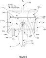
- FIG. 2 an example, which does not fall within the scope of the claimed invention, of an optical Fabry-Perot pressure sensor 30 is illustrated according to a section view.
- the optical Fabry-Perot pressure sensor 30 features similar components as those of the optical Fabry-Perot absolute pressure sensor 10 of the first embodiment, namely a sensor housing 104 , an optical pressure cell 102 and an optical fiber assembly 20.
- the housing back wall 104b features a back input pressure port 154.
- the back input pressure port 154 is a conduit letting the surrounding fluid present at this port (at pressure P i2 aka the pressure in the immediate environment outside the pressure sensor near the back input pressure port 154 ), in the housing back wall 104b of the sensor housing 104 , enter the optical Fabry-Perot pressure sensor 30 , this time in the back area 124 (at pressure P b ).
- Soft sealing body 112 replaces the mounting clamps 108 of the first embodiment as mounting components. The soft sealing body 112 prevents fluid communication between the front area 122 and the back area 124 .
- the Fabry-Perot cavity 140 therefore permits to measure the difference of pressure between the front area 122 and the back area 124 .
- this configuration is particularly attractive for measuring small pressure differences between the two input ports at high static pressure (which would result in high mechanical stresses with prior pressure sensors) with the aforementioned low stress benefits.
- Liquid-filled pressure sensor is a well-known method for protecting the sensor against chemically aggressive fluids.
- oil-filled, silicon MEMs technology pressure sensors have proven to be useful in various industries.
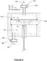
- liquid-filled pressure sensor involves a thin corrugated diaphragm 164 ( Figs. 3-4 ) or bellows 170 ( Figs. 5-6 ), typically made from thin but chemically resistant metal alloys.
- the diaphragm or bellows seals the chamber where the optical pressure cell is located, isolating the cell from the process fluid whose pressure is being measured.
- the chamber is filled with fill-fluid 162 , such as silicone oil, alkylated-aromatic oil or mineral oil, for example.
- fill-fluid 162 such as silicone oil, alkylated-aromatic oil or mineral oil, for example.
- the use of liquid ideally with low compressibility property, is necessary to transfer the pressure applied to the diaphragm or bellow to the optical pressure cell. In the conditions where the sensor is used within a large temperature range, the use of bellows is preferred, as it allows accounting for larger thermal expansion of the fill-fluid 162 .
- Alternative embodiments involve alternative designs and alternative locations for the pressure equalization port 156 permitting to the fluid to be communicated between the front area 122 and the back area 124, and therefore generate the desired pressure equilibrium (i.e., limitation or elimination of the pressure differences around the optical pressure cell 102).
- the desired pressure equilibrium i.e., limitation or elimination of the pressure differences around the optical pressure cell 102
- alternative designs of the sensor housing 104, alternative locations for the front input pressure port 152 and back input pressure port 154 are also possible without departing from the scope of the disclosure.
- Figures 1 , 3 , and 5 illustrate various embodiments of fluid communication arrangements which are useful in allowing pressure equalization between the pressure in the first fluid space on the front side and the pressure in the second fluid space on the back side of the optical pressure cell.
- These fluid communication arrangements include the various passages, ports, conduits, vents, bellows, corrugated diaphragms, holes, etc.
- a conduit is incorporated directly in the body of the optical pressure cell 102 and through diaphragm 110 .
- pressure equalization port 156 would not be required since the conduit in the optical pressure cell 102 would provide the fluid communication arrangement between the first fluid space and the second fluid space.
- the diaphragm 110 does not cover the entire front side 102a of the optical pressure cell 102 .
- a conduit is incorporated in the body of the optical pressure cell 102 only in an area where the diaphragm 110 does not cover the front side 102a of the optical pressure cell 102 .
Landscapes
- Physics & Mathematics (AREA)
- General Physics & Mathematics (AREA)
- Measuring Fluid Pressure (AREA)
- Chemical & Material Sciences (AREA)
- Analytical Chemistry (AREA)
Description
- The present invention relates to optical pressure sensors based on the Fabry-Perot interferometer.
- The subject matter disclosed generally relates to the design of a new optical pressure sensor undergoing less mechanical stresses having detrimental impact on the performance of the sensor.
- There is a variety of existing optical pressure sensors based on the Fabry-Perot interferometer. These types of sensors often differ by their optical assembling and mechanical mounting methods. For example,
U.S. patent 7,689,071 by Belleville teaches that the construction of a Fabry-Perot pressure sensor comprises a bi-directional optical fiber that guides light waves toward a Fabry-Perot-based optical pressure cell made from a glass substrate (the sensor body) and a silicon deflecting diaphragm. A first reflective mirror is deposited within a recessed cavity performed on the top surface of the glass substrate. A deformable silicon diaphragm is bonded or welded to the glass substrate to form a second mirror and also to tightly seal the recessed cavity. The two mirrors, spaced by a distance given by the depth of the recessed cavity constitute a Fabry-Perot interferometer. The depth of the recessed cavity, called the cavity length of the Fabry-Perot interferometer, varies as a function of the differential pressure that may exist between the inside and the outside of the sealed cavity. This optical pressure cell is mounted at the end of an optical fiber within a receiving cavity created in the sensor body of the cell. The receiving cavity is filled with adhesive to secure the cell in place and to seal the whole assembly. One major drawback of this method is the use of adhesive for sealing and bonding. Such sealing and bonding method can only work in low differential pressure environments. Another drawback of this method is that the sensor body needs to be thin (of the order of 200 microns) because no lenses are used to bring the light waves to the pressure cell. Thin optical components are more prone to optical distortion, which may affect the pressure measurement. Another drawback of this method is that the sealing body is applied against the sensor body. Therefore the resulting mechanical force which is required for leak-tight sealing are transferred to the sensor body creating internal stresses in the sensor body. This again can lead to optical distortion of the pressure cell and then affect the accuracy of the pressure measurements. -
U.S. patent 5,128,537 by Beat Halg teaches a different arrangement where the cavity can be put at a given pressure by using a secondary pressure port. This design has similar aforementioned drawbacks with the sealing body applied against the sensor body and the requirement of a thin sensor body. - Alternatively, in
U.S. patent 4,933,545 by Saaski et al. , optical lenses are used to bring the light waves to the optical pressure cell. In that case, the sensor body can be made more robust by increasing its thickness. Nevertheless, this design is also plagued with a similar aforementioned drawback because of the sealing body being applied against the sensor body. Another drawback of this arrangement is that a large differential pressure may exist between the front side and the back side of the optical pressure cell. This may result in the bending of the cell which in turn affects the pressure measurements. - Another arrangement is disclosed in
U.S. Patent 7,614,308 by Berner et al. A support disc is added to the optical pressure cell and the sealing body is applied against the support disc. Although the forces exerted by the sealing body are applied on the support disc, it is not possible to avoid some coupling of these forces to the optical pressure cell knowing that the support disc must be tightly sealed against the cell. Also large pressure differences that may exist between the front side and back side of this optical assembly (support disc with pressure cell) can induce the bending thereof. This in turn can result in the aforementioned optical distortion in the cell which affects the pressure
Additional optical pressure sensors are known fromWO 2011/009222 A1 ,DE 10 2011 081 651 A1WO 2009/155716 A1 . - These aforementioned optical pressure cell arrangements are all exposed in one way or the other to mechanical stresses. This can have a detrimental impact on the performances of the sensor. For example, it is well known in the art that these kinds of stresses tend to relieve themselves unpredictably with time, with temperature change or under vibration and/or shock. These stress relief effects are the main source of unwanted drift of the pressure sensor. The pressure cell is also affected by the bending forces which, for instance, can severely affect the linearity of the sensor response.
- There is therefore a need for a new optical pressure sensor less exposed to mechanical stresses and accordingly being designed to avoid the detrimental impacts associated to these stresses.
- According to the invention, there is provided an optical pressure sensor according to claim 1.
- According to an aspect, the sensor housing defines a conduit extending therewithin from the second fluid space to the first fluid space hence providing the fluid communication arrangement allowing fluid communication and eliminating a difference in pressure between the second fluid space and the first fluid space.
- According to an aspect, the sensor housing comprises walls delimiting the first fluid space and the second fluid space, one of the walls being common to the first fluid space and the second fluid space, namely a shared wall, and the conduit extending from the second fluid space to the first fluid space is provided in the shared wall.
- According to an aspect, the sensor further comprises a front wall further delimiting the first fluid space and wherein a front input pressure port is defined in the front wall and provides fluid communication between the first fluid space and an immediate environment outside the pressure sensor near the front input pressure port.
- According to an aspect, the front input pressure port comprises one of a bellow and a corrugated diaphragm to communicate pressure while preventing ingress of fluid from the immediate environment outside the pressure sensor near the front input pressure port to the first fluid space.
- According to an aspect, the optical pressure sensor further comprises non-sealing mounting clamps to secure the optical pressure cell to the sensor housing.
- According to an aspect, the optical pressure sensor further comprises an optical fiber assembly having a distal end located in the second fluid space proximate the optical pressure cell in an operative manner for transmission and reception of light beams between the optical fiber assembly and the optical pressure cell.
- According to an aspect, the sensor housing further comprises a back wall delimiting the second fluid space and wherein a hole is practiced in the back wall, wherein the optical fiber assembly passes through the hole.
- According to an aspect, the optical fiber assembly comprises an optical fiber and a ferrule housing the optical fiber at the distal end of the optical fiber assembly and further wherein the hole is adapted to hold the ferrule in the back wall.
- Further features and advantages of the present disclosure will become apparent from the following detailed description, taken in combination with the appended drawings, in which:
-
Fig. 1 is a section view illustrating an optical Fabry-Perot absolute pressure sensor in accordance with a first embodiment of the present invention; -
Fig. 2 is a section view illustrating an optical Fabry-Perot differential pressure sensor which does not fall within the scope of the claimed invention; -
Fig. 3 is a section view illustrating an optical Fabry-Perot absolute pressure sensor arranged to protect the sensor cell against corrosive or opaque fluids in accordance with a second embodiment of the present invention; -
Fig. 4 is a section view illustrating an optical Fabry-Perot differential pressure sensor arranged to protect the sensor cell against corrosive or opaque fluids which does not fall within the scope of the claimed invention; -
Fig. 5 is a section view illustrating an optical Fabry-Perot absolute pressure sensor arranged to protect the sensor cell against corrosive or opaque fluids in accordance with a third embodiment of the present invention; and -
Fig. 6 is a section view illustrating an optical Fabry-Perot differential pressure sensor arranged to protect the sensor cell against corrosive or opaque fluids which does not fall within the scope of the claimed invention. - It will be noted that throughout the appended drawings, like features are identified by like reference numerals.
- Using the embodiments of a Fabry-Perot pressure sensor described herein below, one of the major issues (as those discussed herein above) encountered when designing Fabry-Perot pressure sensors is resolved, namely the mechanical stresses that can be induced on the optical pressure cell by the mounting and the packaging configuration of the Fabry-Perot pressure sensor. These stresses can have detrimental impacts on the performance of the Fabry-Perot pressure sensor like drift and high nonlinearity in the response of the pressure sensor. One cause of induced mechanical stresses is a mismatch of the coefficient of thermal expansion (CTE) between the materials of the optical pressure cell, and the materials used for sealing the optical pressure cell in its sensor housing, and the materials of the sensor housing. Another source of mechanical stress is the mechanical force between the seal body and the optical pressure cell required for leak-tight sealing. Another source of stress is the bending of the optical pressure cell due to the large pressure difference that may exist between the back side and front side of the optical pressure cell. These sources of stresses are all greatly decreased with the present solution.
- Referring now to the drawings, and more particularly to
Fig. 1 , a section view of an optical Fabry-Perotabsolute pressure sensor 10 is illustrated. The term "absolute pressure" is directed to the pressure existing at the frontinput pressure port 152 and assuming that the pressure existing in the Fabry-Perot cavity 140 is negligible when compared to that pressure. This contrasts with "differential pressure", where in this case the pressure in the Fabry-Perot cavity 140 cannot be neglected when compared to the pressure existing at theinput pressure port 152. - The optical Fabry-Perot
absolute pressure sensor 10 comprises anoptical pressure cell 102 based on a Fabry-Perot interferometer having afront side 102a and aback side 102b. Theoptical pressure cell 102 is located in thesensor housing 104 inside aside wall recess 106 with soft mounting components, namely with mountingclamps 108 made with soft materials like elastomer o-rings or soft metal o-rings, securely maintaining theoptical pressure cell 102 within theside wall recess 106 but without applying significant force on the cell as it not required here. - The
optical pressure cell 102 comprises a deformable reflectivepressure cell diaphragm 110 bonded or welded in its periphery on the pressurecell front side 102a. With the surface of the Fabry-Perot cavity 140 being composed of reflective material, an operable Fabry-Perot cavity 140 is therefore designed within theoptical pressure cell 102 with the depth of the Fabry-Perot cavity 140 varying under pressure. When thediaphragm 110 is deformed under the difference of pressure at the frontinput pressure port 152 and the Fabry-Perot cavity 140, the distance between two reflective surfaces varies. - The location of the
optical pressure cell 102 within thesensor housing 104 defines and divides two distinct areas: afront area 122 and aback area 124. Thefront area 122 is delimited by thehousing front wall 104a, thehousing side wall 104c and the pressurecell front side 102a, namely thediaphragm 110. Theback area 124 is delimited by the housing backwall 104b, thehousing side wall 104c and the pressure cell backside 102b. In this embodiment, the optical Fabry-Perotabsolute pressure sensor 10 is circular when viewed from the top and therefore there is a singlehousing side wall 104c. From a three-dimensional perspective, thefront area 122 and aback area 124 may also be referred to as volumes or spaces which contain a fluid exerting its pressure on theoptical pressure cell 102. Thefront area 122 and aback area 124 may therefore be referred to as a first fluid space and second fluid space, respectively. Thehousing side wall 104c is also referred to as the shared wall since it is contributes to define both the first fluid space (front area 122) and the second fluid space (back area 124). - The optical Fabry-Perot
absolute pressure sensor 10 further comprises anoptical fiber assembly 20 passing through the housing backwall 104b to have its extremity in theback area 124. Theoptical fiber assembly 20 comprises a bi-directionaloptical fiber 130 located in a protective coating ortubing 132 with its extremity housed in aferrule 134 attached to thesensor housing 104 within a hole in the housing backwall 104b. The bi-directionaloptical fiber 130 extremity ends in the proximity of alens 136. A sealingwindow 138 is affixed to theferrule 134 to seal theoptical fiber assembly 20. The distal end of the optical fiber assembly is located in the proximity of theback side 102b of theoptical pressure cell 102 in an operative manner for light beams to be transmitted and captured between the bi-directionaloptical fiber 130 and theoptical pressure cell 102. Limiting the distance between the end of the optical fiber assembly and theback side 102b of theoptical pressure cell 102 is also advantageous for reducing the shifting of the optical beam caused by a change of the index of refraction of the fluid present in theback area 124 of the of the optical pressure cell. - Located in the
housing front wall 104a, a frontinput pressure port 152, that consists in a conduit (also known as a front conduit) passing through thehousing front wall 104a, allows the fluid in the surrounding area to which the frontinput pressure port 152 is connected or immersed (at pressure Pi, aka the fluid pressure at the front input pressure port 152) to enter in thefront area 122. Apressure equalization port 156 is located in thehousing side wall 104c. Thepressure equalization port 156 consists in a conduit connecting thefront area 122 with theback area 124. Thepressure equalization port 156 allows fluid to communicate between thefront area 122 and theback area 124. Accordingly, theoptical pressure cell 102 is exposed to the same pressure on itsfront side 102a (Pf) and itsback side 102b (Pb), and is therefore free-floating in the fluid present in thesensor housing 104. Furthermore and because the mounting clamps 108 are not used for sealing purposes, very little amount of clamping force is required to maintain theoptical pressure cell 102 in the housingside wall recess 106. With this configuration theoptical pressure cell 102 is thereby not exposed to mechanical stresses that would be caused by a difference in pressure between theback side 102b and thefront side 102a of theoptical pressure cell 102. This is because pressures on both sides of the pressure cell are substantially the same, that is, Pb = Pf = Pi. A because there is no needs for sealing the optical pressure cell against the sensor housing, the significant forces normally required for a leak-tight sealing between the seal body and the optical pressure cell are not present. - With the embodiment of the optical Fabry-Perot
absolute pressure sensor 10, the aforementioned issues of induced mechanical stresses seen with previous configurations are resolved. With the embodiment illustrated onFig. 1 , the fluid pressure at the frontinput pressure port 152 is applied on both thecell front side 102a and cell backside 102b of theoptical pressure cell 102. Therefore, theoptical pressure cell 102 is not exposed to mechanical stress due to a difference in pressure between thecell front side 102a and cell backside 102b. Another advantage of this embodiment is that it eliminates the need for a pressure seal body. Since the pressure is equalized all around theoptical pressure cell 102, there is no need for sealing the optical pressure cell against thesensor housing 104. This eliminates a well-known potential source of mechanical stress on theoptical pressure cell 102 when dealing with high pressure mechanical seals. - Referring now to
Fig. 2 , an example, which does not fall within the scope of the claimed invention, of an optical Fabry-Perot pressure sensor 30 is illustrated according to a section view. - The optical Fabry-
Perot pressure sensor 30 features similar components as those of the optical Fabry-Perotabsolute pressure sensor 10 of the first embodiment, namely asensor housing 104, anoptical pressure cell 102 and anoptical fiber assembly 20. The optical Fabry-Perot pressure sensor 30 further comprises a frontinput pressure port 152 located on thehousing front wall 104a and letting the surrounding fluid present at this port (at pressure Pi1, aka the pressure in the immediate environment outside the pressure sensor near the front input pressure port 152) enter thefront area 122 and therefore permitting equalization of the pressure in the front area 122 (Pf) with the pressure (Pi1) existing at the frontinput pressure port 154; that is, Pf = Pi1. - Similarly, the housing back
wall 104b features a backinput pressure port 154. The backinput pressure port 154 is a conduit letting the surrounding fluid present at this port (at pressure Pi2 aka the pressure in the immediate environment outside the pressure sensor near the back input pressure port 154), in the housing backwall 104b of thesensor housing 104, enter the optical Fabry-Perot pressure sensor 30, this time in the back area 124 (at pressure Pb).Soft sealing body 112 replaces the mounting clamps 108 of the first embodiment as mounting components. Thesoft sealing body 112 prevents fluid communication between thefront area 122 and theback area 124. Avent channel 160 passing through theoptical pressure cell 102 up to the Fabry-Perot cavity 140 equalizes the pressure behind the diaphragm 110 (Pc) with the pressure at theback side 102b (Pb) of theoptical pressure cell 102; that is, Pb = Pc = Pi2. The Fabry-Perot cavity 140 therefore permits to measure the difference of pressure between thefront area 122 and theback area 124. - Accordingly, this configuration is particularly attractive for measuring small pressure differences between the two input ports at high static pressure (which would result in high mechanical stresses with prior pressure sensors) with the aforementioned low stress benefits.
- With reference to
Figures 3 ,4 ,5 and6 , in the presence of chemically aggressive fluids, it is required to protect the optical pressure cell and other sensitive components that could be damaged by corrosion or other types of chemical ingression. Liquid-filled pressure sensor is a well-known method for protecting the sensor against chemically aggressive fluids. For example, oil-filled, silicon MEMs technology pressure sensors have proven to be useful in various industries. - The basic construction of liquid-filled pressure sensor involves a thin corrugated diaphragm 164 (
Figs. 3-4 ) or bellows 170 (Figs. 5-6 ), typically made from thin but chemically resistant metal alloys. The diaphragm or bellows seals the chamber where the optical pressure cell is located, isolating the cell from the process fluid whose pressure is being measured. The chamber is filled with fill-fluid 162, such as silicone oil, alkylated-aromatic oil or mineral oil, for example. The use of liquid, ideally with low compressibility property, is necessary to transfer the pressure applied to the diaphragm or bellow to the optical pressure cell. In the conditions where the sensor is used within a large temperature range, the use of bellows is preferred, as it allows accounting for larger thermal expansion of the fill-fluid 162. - Alternative embodiments, not illustrated, involve alternative designs and alternative locations for the
pressure equalization port 156 permitting to the fluid to be communicated between thefront area 122 and theback area 124, and therefore generate the desired pressure equilibrium (i.e., limitation or elimination of the pressure differences around the optical pressure cell 102). For instance, alternative designs of thesensor housing 104, alternative locations for the frontinput pressure port 152 and backinput pressure port 154 are also possible without departing from the scope of the disclosure. - Similarly, alternative solutions exist for fixing the
optical pressure cell 102 within thesensor housing 104 without departing from the scope of the invention. For example, various mounting and clamping methods are given in the book entitled "Mounting Optics in Optical Instruments", by Paul R Yoder Jr. Many of the mounting and clamping methods described in this book could be used for mounting theoptical pressure cell 102 for purposes similar to those presented herein but do not need to be described further. According to alternative housing designs, the way theoptical pressure cell 102 is maintained in location in thesensor housing 104 may vary, and may either require the illustratedside wall recess 106 or not, or alternative configurations and/or components can be provided to secure theoptical pressure cell 102 in place without applying force inducing mechanical stresses on theoptical pressure cell 102. Similarly, those skilled in the art will understand that there exists various ways to achieve pressure equalization as described herein. For example orifices or channels could be made in the mountingclamp 108 proving same pressure on both side of the optical pressure cell. - It should be noted that
Figures 1 ,3 , and5 illustrate various embodiments of fluid communication arrangements which are useful in allowing pressure equalization between the pressure in the first fluid space on the front side and the pressure in the second fluid space on the back side of the optical pressure cell. These fluid communication arrangements include the various passages, ports, conduits, vents, bellows, corrugated diaphragms, holes, etc. - According to yet another non-illustrated embodiment, a conduit is incorporated directly in the body of the
optical pressure cell 102 and throughdiaphragm 110. In such a case,pressure equalization port 156 would not be required since the conduit in theoptical pressure cell 102 would provide the fluid communication arrangement between the first fluid space and the second fluid space. A similar, yet slightly different embodiment, would be possible where thediaphragm 110 does not cover the entirefront side 102a of theoptical pressure cell 102. In such a case, a conduit is incorporated in the body of theoptical pressure cell 102 only in an area where thediaphragm 110 does not cover thefront side 102a of theoptical pressure cell 102.
Claims (9)
- An optical pressure sensor (10) comprising:- a sensor housing (104);- a Fabry-Perot interferometer optical pressure cell (102) mounted within the sensor housing (104),characterized in that:- the Fabry-Perot interferometer optical pressure cell (102) divides the sensor housing (104) into a first fluid space (122) and a second fluid space (124), the Fabry-Perot interferometer optical pressure cell (102) comprising a front side (102a) exposed to a pressure in the first fluid space (122) and a back side (102b) exposed to a pressure in the second fluid space (124); and- the optical pressure sensor (10) comprises a fluid communication arrangement (156) allowing pressure equalization between the pressure in the first fluid space (122) on the front side (102a) and the pressure in the second fluid space (124) on the back side (102b) of the Fabry-Perot interferometer optical pressure cell (102).
- The pressure sensor (10) of claim 1, wherein the sensor housing (104) defines a conduit extending therewithin from the second fluid space (124) to the first fluid space (122) hence providing the fluid communication arrangement (156) allowing fluid communication and eliminating a difference in pressure between the second fluid space (124) and the first fluid space (122).
- The pressure sensor (10) of claim 2, wherein the sensor housing (104) comprises walls (104a, 104b, 104c) delimiting the first fluid space (122) and the second fluid space (124), one of the walls (104c) being common to the first fluid space (122) and the second fluid space (124), namely a shared wall, and the conduit (156) extending from the second fluid space (124) to the first fluid space (122) is provided in the shared wall (104c).
- The pressure sensor (10) of claim 3, wherein the sensor (10) further comprises a front wall (104a) further delimiting the first fluid space (122) and wherein a front input pressure port (152) is defined in the front wall (104a) and provides fluid communication between the first fluid space (122) and an immediate environment outside the pressure sensor (10) near the front input pressure port (152).
- The pressure sensor (10) of claim 4, wherein the front input pressure port (152) comprises one of a bellow and a corrugated diaphragm to communicate pressure while preventing ingress of fluid from the immediate environment outside the pressure sensor (10) near the front input pressure port (152) to the first fluid space (122).
- The pressure sensor (10) of claim 2, further comprising non-sealing mounting clamps (108) to secure the Fabry-Perot interferometer optical pressure cell (102) to the sensor housing (104).
- The pressure sensor (10) of claim 1, further comprising an optical fiber assembly (20) having a distal end located in the second fluid space (124) proximate the Fabry-Perot interferometer optical pressure cell (102) in an operative manner for transmission and reception of light beams between the optical fiber assembly (20) and the Fabry-Perot interferometer optical pressure cell (102).
- The pressure sensor (10) of claim 7, wherein the sensor housing (104) further comprises a back wall (104b) delimiting the second fluid space (124) and wherein a hole is practiced in the back wall (104b), wherein the optical fiber assembly (20) passes through the hole.
- The pressure sensor (10) of claim 8, wherein the optical fiber assembly (20) comprises an optical fiber (130) and a ferrule (134) housing the optical fiber (130) at the distal end of the optical fiber assembly (20) and further wherein the hole is adapted to hold the ferrule (134) in the back wall (104b).
Applications Claiming Priority (2)
| Application Number | Priority Date | Filing Date | Title |
|---|---|---|---|
| US201562221313P | 2015-09-21 | 2015-09-21 | |
| PCT/CA2016/051101 WO2017049392A1 (en) | 2015-09-21 | 2016-09-21 | Optical pressure sensor with reduced mechanical stresses |
Publications (3)
| Publication Number | Publication Date |
|---|---|
| EP3353517A1 EP3353517A1 (en) | 2018-08-01 |
| EP3353517A4 EP3353517A4 (en) | 2019-01-16 |
| EP3353517B1 true EP3353517B1 (en) | 2020-03-04 |
Family
ID=58277058
Family Applications (1)
| Application Number | Title | Priority Date | Filing Date |
|---|---|---|---|
| EP16847679.4A Active EP3353517B1 (en) | 2015-09-21 | 2016-09-21 | Optical pressure sensor with reduced mechanical stresses |
Country Status (8)
| Country | Link |
|---|---|
| US (1) | US10082437B2 (en) |
| EP (1) | EP3353517B1 (en) |
| JP (3) | JP2018527592A (en) |
| CN (1) | CN108027294B (en) |
| CA (1) | CA2999071C (en) |
| ES (1) | ES2789448T3 (en) |
| PT (1) | PT3353517T (en) |
| WO (1) | WO2017049392A1 (en) |
Cited By (5)
| Publication number | Priority date | Publication date | Assignee | Title |
|---|---|---|---|---|
| US11819700B2 (en) | 2021-08-06 | 2023-11-21 | Solo Pace Inc. | Systems, methods, and apparatus for external cardiac pacing |
| US20230393005A1 (en) * | 2020-10-20 | 2023-12-07 | Davidson Instruments, Inc. | Extrinsic fabry-perot absolute pressure sensor |
| US11872403B2 (en) | 2021-08-06 | 2024-01-16 | Solo Pace Inc. | Systems, methods, and apparatus for external cardiac pacing |
| WO2024261138A1 (en) * | 2023-06-22 | 2024-12-26 | Paris Sciences Et Lettres | System for measuring differential pressure in an underwater environment |
| US12357833B2 (en) | 2023-08-01 | 2025-07-15 | Merit Medical Systems, Inc. | Systems, methods, and apparatus for ambulatory cardiac pacing |
Families Citing this family (12)
| Publication number | Priority date | Publication date | Assignee | Title |
|---|---|---|---|---|
| US20130218032A1 (en) | 2010-11-09 | 2013-08-22 | Opsens Inc. | Guidewire with internal pressure sensor |
| NL2017595A (en) * | 2015-11-10 | 2017-05-26 | Asml Netherlands Bv | Proximity sensor, lithographic apparatus and device manufacturing method |
| CN107063554B (en) * | 2017-04-01 | 2019-07-09 | 天津大学 | A kind of integrated fiber big pressure sensor and preparation method thereof |
| US11137311B2 (en) * | 2018-09-27 | 2021-10-05 | Georgia Tech Research Corporation | Pressure sensing devices with improved force threshold |
| DE102019114698B3 (en) * | 2019-05-31 | 2020-09-17 | Bundesrepublik Deutschland, Vertreten Durch Das Bundesministerium Für Wirtschaft Und Energie, Dieses Vertreten Durch Den Präsidenten Der Physikalischen Bundesanstalt | Gas property measuring device |
| CN112729507B (en) * | 2019-10-14 | 2024-10-29 | 同济大学 | Road surface dynamic monitoring device and system |
| CN110850113B (en) * | 2019-12-02 | 2020-11-17 | 西安交通大学 | Fabry-Perot optical MEMS acceleration sensor with low lateral sensitivity |
| CN111366189A (en) * | 2020-02-24 | 2020-07-03 | 北京理工大学 | System and method for sensing pressure or vibration |
| US20240255372A1 (en) * | 2021-05-30 | 2024-08-01 | Ezmems Ltd. | Creep/deformation compensation for sensors |
| JP7701243B2 (en) * | 2021-11-01 | 2025-07-01 | 朝日インテック株式会社 | Optical pressure sensor and method for manufacturing the same |
| CN114993550B (en) * | 2022-06-16 | 2024-03-22 | 电子科技大学 | High-reliability differential pressure sensor and sensing method |
| CN115790955B (en) * | 2023-02-03 | 2023-04-21 | 广东海洋大学 | Fabry-Perot interference dynamic pressure sensing device and manufacturing method thereof |
Citations (1)
| Publication number | Priority date | Publication date | Assignee | Title |
|---|---|---|---|---|
| US5684253A (en) * | 1997-01-08 | 1997-11-04 | Honeywell Inc. | Differential pressure sensor with stress reducing pressure balancing means |
Family Cites Families (26)
| Publication number | Priority date | Publication date | Assignee | Title |
|---|---|---|---|---|
| JPS5750047U (en) * | 1980-09-05 | 1982-03-20 | ||
| DE3341845A1 (en) * | 1983-11-19 | 1985-05-30 | Philips Patentverwaltung Gmbh, 2000 Hamburg | Optical pressure-measuring device |
| GB8506589D0 (en) * | 1985-03-14 | 1985-04-17 | Ici Plc | Pressure sensor |
| JPS6486031A (en) * | 1987-09-29 | 1989-03-30 | Toshiba Corp | Pressure detector |
| US5026984A (en) * | 1990-01-16 | 1991-06-25 | Sperry Marine, Inc. | Methods for sensing temperature, pressure and liquid level and variable ratio fiber optic coupler sensors therefor |
| EP0460357A3 (en) * | 1990-06-08 | 1992-07-29 | Landis & Gyr Betriebs Ag | Device for optical measurement of pressure differences |
| DE4035373C2 (en) * | 1990-11-07 | 1994-06-16 | Fibronix Sensoren Gmbh | Fiber optic pressure or displacement sensor |
| US5414509A (en) * | 1993-03-08 | 1995-05-09 | Associated Universities, Inc. | Optical pressure/density measuring means |
| JP4864266B2 (en) * | 2000-02-11 | 2012-02-01 | ローズマウント インコーポレイテッド | Optical pressure sensor |
| DE10024588A1 (en) * | 2000-05-19 | 2001-11-22 | Endress Hauser Gmbh Co | Pressure monitoring device has evaluation unit which determines pressure effected on partial area of laser crystal, based on different frequencies of laser radiation in various polarization directions |
| JP2002129941A (en) | 2000-10-19 | 2002-05-09 | Isuzu Ceramics Res Inst Co Ltd | Exhaust particulate filter for diesel engine |
| NO315177B1 (en) * | 2001-11-29 | 2003-07-21 | Sinvent As | Optical offset sensor |
| US7017417B2 (en) * | 2004-02-10 | 2006-03-28 | Weatherford/Lamb, Inc. | Pressure sensor assembly suitable for use in harsh environments |
| US20050195402A1 (en) * | 2004-03-04 | 2005-09-08 | Russell May | Crystalline optical fiber sensors for harsh environments |
| DE102006024381B3 (en) * | 2006-05-24 | 2007-12-06 | Fraunhofer-Gesellschaft zur Förderung der angewandten Forschung e.V. | MEMS vacuum sensor based on the friction principle |
| JP2008107295A (en) * | 2006-10-27 | 2008-05-08 | Suncall Corp | Optical pressure sensor and its manufacturing method |
| EP2072986B1 (en) | 2007-12-18 | 2016-08-10 | Services Pétroliers Schlumberger | A pressure measuring device and method |
| CH700454B1 (en) | 2007-12-20 | 2012-10-15 | Inficon Gmbh | Arrangement for a membrane pressure measuring cell. |
| US7707891B2 (en) * | 2008-06-27 | 2010-05-04 | Inficon Gmbh | Optical interferometric pressure sensor |
| CH701500A1 (en) * | 2009-07-24 | 2011-01-31 | Inficon Gmbh | Pressure measuring cell arrangement with an optical diaphragm pressure measuring cell. |
| US8490497B2 (en) * | 2010-03-25 | 2013-07-23 | University Of Southern California | Microelectromechanical (MEMS) pressure transducer |
| US8752435B2 (en) * | 2011-03-09 | 2014-06-17 | Claude Belleville | Miniature high sensitivity pressure sensor |
| DE102011081651A1 (en) * | 2011-08-26 | 2013-02-28 | Endress + Hauser Gmbh + Co. Kg | Interferometric pressure sensor |
| JP5778619B2 (en) * | 2012-05-02 | 2015-09-16 | セイコーインスツル株式会社 | Pressure sensor |
| US9775523B2 (en) * | 2013-10-14 | 2017-10-03 | Boston Scientific Scimed, Inc. | Pressure sensing guidewire and methods for calculating fractional flow reserve |
| WO2016019207A1 (en) * | 2014-08-01 | 2016-02-04 | Boston Scientific Scimed, Inc. | Pressure sensing guidewires |
-
2016
- 2016-09-21 PT PT168476794T patent/PT3353517T/en unknown
- 2016-09-21 EP EP16847679.4A patent/EP3353517B1/en active Active
- 2016-09-21 ES ES16847679T patent/ES2789448T3/en active Active
- 2016-09-21 WO PCT/CA2016/051101 patent/WO2017049392A1/en not_active Ceased
- 2016-09-21 CN CN201680054581.4A patent/CN108027294B/en active Active
- 2016-09-21 US US15/271,987 patent/US10082437B2/en active Active
- 2016-09-21 JP JP2018533982A patent/JP2018527592A/en active Pending
- 2016-09-21 CA CA2999071A patent/CA2999071C/en active Active
-
2021
- 2021-09-10 JP JP2021147655A patent/JP7297833B2/en active Active
-
2023
- 2023-04-12 JP JP2023064870A patent/JP2023100647A/en active Pending
Patent Citations (1)
| Publication number | Priority date | Publication date | Assignee | Title |
|---|---|---|---|---|
| US5684253A (en) * | 1997-01-08 | 1997-11-04 | Honeywell Inc. | Differential pressure sensor with stress reducing pressure balancing means |
Cited By (8)
| Publication number | Priority date | Publication date | Assignee | Title |
|---|---|---|---|---|
| US20230393005A1 (en) * | 2020-10-20 | 2023-12-07 | Davidson Instruments, Inc. | Extrinsic fabry-perot absolute pressure sensor |
| US12560500B2 (en) * | 2020-10-20 | 2026-02-24 | Davidson Instruments, Inc. | Extrinsic Fabry-Perot absolute pressure sensor |
| US11819700B2 (en) | 2021-08-06 | 2023-11-21 | Solo Pace Inc. | Systems, methods, and apparatus for external cardiac pacing |
| US11872403B2 (en) | 2021-08-06 | 2024-01-16 | Solo Pace Inc. | Systems, methods, and apparatus for external cardiac pacing |
| US12161872B2 (en) | 2021-08-06 | 2024-12-10 | Solo Pace Inc. | Systems, methods, and apparatus for external cardiac pacing |
| WO2024261138A1 (en) * | 2023-06-22 | 2024-12-26 | Paris Sciences Et Lettres | System for measuring differential pressure in an underwater environment |
| FR3150288A1 (en) * | 2023-06-22 | 2024-12-27 | Paris Sciences Et Lettres | Differential pressure measurement system in underwater environment |
| US12357833B2 (en) | 2023-08-01 | 2025-07-15 | Merit Medical Systems, Inc. | Systems, methods, and apparatus for ambulatory cardiac pacing |
Also Published As
| Publication number | Publication date |
|---|---|
| JP2023100647A (en) | 2023-07-19 |
| JP2018527592A (en) | 2018-09-20 |
| ES2789448T3 (en) | 2020-10-26 |
| EP3353517A1 (en) | 2018-08-01 |
| CN108027294B (en) | 2020-05-19 |
| US10082437B2 (en) | 2018-09-25 |
| US20170082514A1 (en) | 2017-03-23 |
| PT3353517T (en) | 2020-05-20 |
| CA2999071C (en) | 2024-01-16 |
| CN108027294A (en) | 2018-05-11 |
| JP2022000647A (en) | 2022-01-04 |
| JP7297833B2 (en) | 2023-06-26 |
| EP3353517A4 (en) | 2019-01-16 |
| WO2017049392A1 (en) | 2017-03-30 |
| CA2999071A1 (en) | 2017-03-30 |
Similar Documents
| Publication | Publication Date | Title |
|---|---|---|
| JP7297833B2 (en) | Optical pressure sensor with reduced mechanical stress | |
| EP2072986B1 (en) | A pressure measuring device and method | |
| US7614308B2 (en) | Diaphragm pressure measuring cell arrangement | |
| US7047816B2 (en) | Optical differential pressure transducer utilizing a bellows and flexure system | |
| US5386729A (en) | Temperature compensated microbend fiber optic differential pressure transducer | |
| EP2932323B1 (en) | Optical fibre alignment | |
| CA2676246C (en) | Transducer for measuring environmental parameters | |
| JP6762466B2 (en) | Sensor system with pressure sensor and one or more pressure sensors | |
| US6549488B2 (en) | Fiber-optic hydrophone | |
| US20070227252A1 (en) | Differential pressure transducer configurations including displacement sensor | |
| US9810594B2 (en) | Thermally stable high temperature pressure and acceleration optical interferometric sensors | |
| US8353215B2 (en) | Torque output differential pressure sensor | |
| US9829307B2 (en) | Silicon based pressure and acceleration optical interferometric sensors with housing assembly | |
| KR20120036351A (en) | Pressure measuring cell arrangement comprising an optical diaphragm prssure measuing cell | |
| GB2466929A (en) | Pressure sensor device comprising flexible diaphragm with integral optical sensor | |
| JP4851480B2 (en) | Flow velocity measuring device | |
| EP2537014B1 (en) | Fluid pressure monitoring apparatus | |
| CA2461424C (en) | Optical differential pressure transducer utilizing a bellows and flexure system | |
| US12411072B2 (en) | Method for installing one or more optical elements in a housing | |
| Thompson | Corporation, Sugar Land, TX (US) | |
| JPH03223639A (en) | Differential-pressure detecting device | |
| JPH058451U (en) | Pressure transducer |
Legal Events
| Date | Code | Title | Description |
|---|---|---|---|
| STAA | Information on the status of an ep patent application or granted ep patent |
Free format text: STATUS: THE INTERNATIONAL PUBLICATION HAS BEEN MADE |
|
| PUAI | Public reference made under article 153(3) epc to a published international application that has entered the european phase |
Free format text: ORIGINAL CODE: 0009012 |
|
| STAA | Information on the status of an ep patent application or granted ep patent |
Free format text: STATUS: REQUEST FOR EXAMINATION WAS MADE |
|
| 17P | Request for examination filed |
Effective date: 20180412 |
|
| AK | Designated contracting states |
Kind code of ref document: A1 Designated state(s): AL AT BE BG CH CY CZ DE DK EE ES FI FR GB GR HR HU IE IS IT LI LT LU LV MC MK MT NL NO PL PT RO RS SE SI SK SM TR |
|
| AX | Request for extension of the european patent |
Extension state: BA ME |
|
| RIC1 | Information provided on ipc code assigned before grant |
Ipc: G01L 19/00 20060101ALI20180907BHEP Ipc: G01D 5/26 20060101ALI20180907BHEP Ipc: G01L 13/02 20060101ALI20180907BHEP Ipc: G01L 11/02 20060101AFI20180907BHEP Ipc: G01L 9/00 20060101ALI20180907BHEP Ipc: G01L 13/00 20060101ALI20180907BHEP Ipc: G01L 19/06 20060101ALI20180907BHEP |
|
| DAV | Request for validation of the european patent (deleted) | ||
| DAX | Request for extension of the european patent (deleted) | ||
| A4 | Supplementary search report drawn up and despatched |
Effective date: 20181218 |
|
| RIC1 | Information provided on ipc code assigned before grant |
Ipc: G01L 13/02 20060101ALI20181212BHEP Ipc: G01L 9/00 20060101ALI20181212BHEP Ipc: G01L 19/00 20060101ALI20181212BHEP Ipc: G01L 13/00 20060101ALI20181212BHEP Ipc: G01L 19/06 20060101ALI20181212BHEP Ipc: G01L 11/02 20060101AFI20181212BHEP Ipc: G01D 5/26 20060101ALI20181212BHEP |
|
| GRAP | Despatch of communication of intention to grant a patent |
Free format text: ORIGINAL CODE: EPIDOSNIGR1 |
|
| STAA | Information on the status of an ep patent application or granted ep patent |
Free format text: STATUS: GRANT OF PATENT IS INTENDED |
|
| INTG | Intention to grant announced |
Effective date: 20191127 |
|
| GRAS | Grant fee paid |
Free format text: ORIGINAL CODE: EPIDOSNIGR3 |
|
| GRAA | (expected) grant |
Free format text: ORIGINAL CODE: 0009210 |
|
| STAA | Information on the status of an ep patent application or granted ep patent |
Free format text: STATUS: THE PATENT HAS BEEN GRANTED |
|
| AK | Designated contracting states |
Kind code of ref document: B1 Designated state(s): AL AT BE BG CH CY CZ DE DK EE ES FI FR GB GR HR HU IE IS IT LI LT LU LV MC MK MT NL NO PL PT RO RS SE SI SK SM TR |
|
| REG | Reference to a national code |
Ref country code: GB Ref legal event code: FG4D |
|
| REG | Reference to a national code |
Ref country code: CH Ref legal event code: EP |
|
| REG | Reference to a national code |
Ref country code: AT Ref legal event code: REF Ref document number: 1240952 Country of ref document: AT Kind code of ref document: T Effective date: 20200315 |
|
| REG | Reference to a national code |
Ref country code: DE Ref legal event code: R096 Ref document number: 602016031267 Country of ref document: DE |
|
| REG | Reference to a national code |
Ref country code: IE Ref legal event code: FG4D |
|
| REG | Reference to a national code |
Ref country code: PT Ref legal event code: SC4A Ref document number: 3353517 Country of ref document: PT Date of ref document: 20200520 Kind code of ref document: T Free format text: AVAILABILITY OF NATIONAL TRANSLATION Effective date: 20200513 |
|
| REG | Reference to a national code |
Ref country code: CH Ref legal event code: NV Representative=s name: KATZAROV SA, CH |
|
| REG | Reference to a national code |
Ref country code: SE Ref legal event code: TRGR |
|
| RAP2 | Party data changed (patent owner data changed or rights of a patent transferred) |
Owner name: OPSENS SOLUTIONS INC. |
|
| PG25 | Lapsed in a contracting state [announced via postgrant information from national office to epo] |
Ref country code: RS Free format text: LAPSE BECAUSE OF FAILURE TO SUBMIT A TRANSLATION OF THE DESCRIPTION OR TO PAY THE FEE WITHIN THE PRESCRIBED TIME-LIMIT Effective date: 20200304 Ref country code: FI Free format text: LAPSE BECAUSE OF FAILURE TO SUBMIT A TRANSLATION OF THE DESCRIPTION OR TO PAY THE FEE WITHIN THE PRESCRIBED TIME-LIMIT Effective date: 20200304 Ref country code: NO Free format text: LAPSE BECAUSE OF FAILURE TO SUBMIT A TRANSLATION OF THE DESCRIPTION OR TO PAY THE FEE WITHIN THE PRESCRIBED TIME-LIMIT Effective date: 20200604 |
|
| REG | Reference to a national code |
Ref country code: NL Ref legal event code: MP Effective date: 20200304 |
|
| PG25 | Lapsed in a contracting state [announced via postgrant information from national office to epo] |
Ref country code: LV Free format text: LAPSE BECAUSE OF FAILURE TO SUBMIT A TRANSLATION OF THE DESCRIPTION OR TO PAY THE FEE WITHIN THE PRESCRIBED TIME-LIMIT Effective date: 20200304 Ref country code: BG Free format text: LAPSE BECAUSE OF FAILURE TO SUBMIT A TRANSLATION OF THE DESCRIPTION OR TO PAY THE FEE WITHIN THE PRESCRIBED TIME-LIMIT Effective date: 20200604 Ref country code: HR Free format text: LAPSE BECAUSE OF FAILURE TO SUBMIT A TRANSLATION OF THE DESCRIPTION OR TO PAY THE FEE WITHIN THE PRESCRIBED TIME-LIMIT Effective date: 20200304 Ref country code: GR Free format text: LAPSE BECAUSE OF FAILURE TO SUBMIT A TRANSLATION OF THE DESCRIPTION OR TO PAY THE FEE WITHIN THE PRESCRIBED TIME-LIMIT Effective date: 20200605 |
|
| REG | Reference to a national code |
Ref country code: LT Ref legal event code: MG4D |
|
| PG25 | Lapsed in a contracting state [announced via postgrant information from national office to epo] |
Ref country code: NL Free format text: LAPSE BECAUSE OF FAILURE TO SUBMIT A TRANSLATION OF THE DESCRIPTION OR TO PAY THE FEE WITHIN THE PRESCRIBED TIME-LIMIT Effective date: 20200304 |
|
| REG | Reference to a national code |
Ref country code: ES Ref legal event code: FG2A Ref document number: 2789448 Country of ref document: ES Kind code of ref document: T3 Effective date: 20201026 |
|
| PG25 | Lapsed in a contracting state [announced via postgrant information from national office to epo] |
Ref country code: SK Free format text: LAPSE BECAUSE OF FAILURE TO SUBMIT A TRANSLATION OF THE DESCRIPTION OR TO PAY THE FEE WITHIN THE PRESCRIBED TIME-LIMIT Effective date: 20200304 Ref country code: RO Free format text: LAPSE BECAUSE OF FAILURE TO SUBMIT A TRANSLATION OF THE DESCRIPTION OR TO PAY THE FEE WITHIN THE PRESCRIBED TIME-LIMIT Effective date: 20200304 Ref country code: IS Free format text: LAPSE BECAUSE OF FAILURE TO SUBMIT A TRANSLATION OF THE DESCRIPTION OR TO PAY THE FEE WITHIN THE PRESCRIBED TIME-LIMIT Effective date: 20200704 Ref country code: EE Free format text: LAPSE BECAUSE OF FAILURE TO SUBMIT A TRANSLATION OF THE DESCRIPTION OR TO PAY THE FEE WITHIN THE PRESCRIBED TIME-LIMIT Effective date: 20200304 Ref country code: SM Free format text: LAPSE BECAUSE OF FAILURE TO SUBMIT A TRANSLATION OF THE DESCRIPTION OR TO PAY THE FEE WITHIN THE PRESCRIBED TIME-LIMIT Effective date: 20200304 Ref country code: LT Free format text: LAPSE BECAUSE OF FAILURE TO SUBMIT A TRANSLATION OF THE DESCRIPTION OR TO PAY THE FEE WITHIN THE PRESCRIBED TIME-LIMIT Effective date: 20200304 Ref country code: CZ Free format text: LAPSE BECAUSE OF FAILURE TO SUBMIT A TRANSLATION OF THE DESCRIPTION OR TO PAY THE FEE WITHIN THE PRESCRIBED TIME-LIMIT Effective date: 20200304 |
|
| REG | Reference to a national code |
Ref country code: AT Ref legal event code: MK05 Ref document number: 1240952 Country of ref document: AT Kind code of ref document: T Effective date: 20200304 |
|
| REG | Reference to a national code |
Ref country code: DE Ref legal event code: R097 Ref document number: 602016031267 Country of ref document: DE |
|
| PLBE | No opposition filed within time limit |
Free format text: ORIGINAL CODE: 0009261 |
|
| STAA | Information on the status of an ep patent application or granted ep patent |
Free format text: STATUS: NO OPPOSITION FILED WITHIN TIME LIMIT |
|
| PG25 | Lapsed in a contracting state [announced via postgrant information from national office to epo] |
Ref country code: AT Free format text: LAPSE BECAUSE OF FAILURE TO SUBMIT A TRANSLATION OF THE DESCRIPTION OR TO PAY THE FEE WITHIN THE PRESCRIBED TIME-LIMIT Effective date: 20200304 Ref country code: DK Free format text: LAPSE BECAUSE OF FAILURE TO SUBMIT A TRANSLATION OF THE DESCRIPTION OR TO PAY THE FEE WITHIN THE PRESCRIBED TIME-LIMIT Effective date: 20200304 |
|
| 26N | No opposition filed |
Effective date: 20201207 |
|
| PG25 | Lapsed in a contracting state [announced via postgrant information from national office to epo] |
Ref country code: SI Free format text: LAPSE BECAUSE OF FAILURE TO SUBMIT A TRANSLATION OF THE DESCRIPTION OR TO PAY THE FEE WITHIN THE PRESCRIBED TIME-LIMIT Effective date: 20200304 Ref country code: PL Free format text: LAPSE BECAUSE OF FAILURE TO SUBMIT A TRANSLATION OF THE DESCRIPTION OR TO PAY THE FEE WITHIN THE PRESCRIBED TIME-LIMIT Effective date: 20200304 |
|
| REG | Reference to a national code |
Ref country code: BE Ref legal event code: MM Effective date: 20200930 |
|
| PG25 | Lapsed in a contracting state [announced via postgrant information from national office to epo] |
Ref country code: LU Free format text: LAPSE BECAUSE OF NON-PAYMENT OF DUE FEES Effective date: 20200921 |
|
| PG25 | Lapsed in a contracting state [announced via postgrant information from national office to epo] |
Ref country code: BE Free format text: LAPSE BECAUSE OF NON-PAYMENT OF DUE FEES Effective date: 20200930 |
|
| PG25 | Lapsed in a contracting state [announced via postgrant information from national office to epo] |
Ref country code: TR Free format text: LAPSE BECAUSE OF FAILURE TO SUBMIT A TRANSLATION OF THE DESCRIPTION OR TO PAY THE FEE WITHIN THE PRESCRIBED TIME-LIMIT Effective date: 20200304 Ref country code: MT Free format text: LAPSE BECAUSE OF FAILURE TO SUBMIT A TRANSLATION OF THE DESCRIPTION OR TO PAY THE FEE WITHIN THE PRESCRIBED TIME-LIMIT Effective date: 20200304 Ref country code: CY Free format text: LAPSE BECAUSE OF FAILURE TO SUBMIT A TRANSLATION OF THE DESCRIPTION OR TO PAY THE FEE WITHIN THE PRESCRIBED TIME-LIMIT Effective date: 20200304 |
|
| PG25 | Lapsed in a contracting state [announced via postgrant information from national office to epo] |
Ref country code: MK Free format text: LAPSE BECAUSE OF FAILURE TO SUBMIT A TRANSLATION OF THE DESCRIPTION OR TO PAY THE FEE WITHIN THE PRESCRIBED TIME-LIMIT Effective date: 20200304 Ref country code: MC Free format text: LAPSE BECAUSE OF FAILURE TO SUBMIT A TRANSLATION OF THE DESCRIPTION OR TO PAY THE FEE WITHIN THE PRESCRIBED TIME-LIMIT Effective date: 20200304 Ref country code: AL Free format text: LAPSE BECAUSE OF FAILURE TO SUBMIT A TRANSLATION OF THE DESCRIPTION OR TO PAY THE FEE WITHIN THE PRESCRIBED TIME-LIMIT Effective date: 20200304 |
|
| P01 | Opt-out of the competence of the unified patent court (upc) registered |
Effective date: 20230428 |
|
| REG | Reference to a national code |
Ref country code: CH Ref legal event code: U11 Free format text: ST27 STATUS EVENT CODE: U-0-0-U10-U11 (AS PROVIDED BY THE NATIONAL OFFICE) Effective date: 20251001 |
|
| PGFP | Annual fee paid to national office [announced via postgrant information from national office to epo] |
Ref country code: PT Payment date: 20250714 Year of fee payment: 10 |
|
| PGFP | Annual fee paid to national office [announced via postgrant information from national office to epo] |
Ref country code: DE Payment date: 20250904 Year of fee payment: 10 |
|
| PGFP | Annual fee paid to national office [announced via postgrant information from national office to epo] |
Ref country code: IT Payment date: 20250908 Year of fee payment: 10 |
|
| PGFP | Annual fee paid to national office [announced via postgrant information from national office to epo] |
Ref country code: GB Payment date: 20250714 Year of fee payment: 10 |
|
| PGFP | Annual fee paid to national office [announced via postgrant information from national office to epo] |
Ref country code: FR Payment date: 20250812 Year of fee payment: 10 |
|
| PGFP | Annual fee paid to national office [announced via postgrant information from national office to epo] |
Ref country code: SE Payment date: 20250805 Year of fee payment: 10 |
|
| PGFP | Annual fee paid to national office [announced via postgrant information from national office to epo] |
Ref country code: IE Payment date: 20250814 Year of fee payment: 10 |
|
| PGFP | Annual fee paid to national office [announced via postgrant information from national office to epo] |
Ref country code: CH Payment date: 20251001 Year of fee payment: 10 |
|
| PGFP | Annual fee paid to national office [announced via postgrant information from national office to epo] |
Ref country code: ES Payment date: 20251001 Year of fee payment: 10 |