EP3353458B1 - Quick-fit connector for pneumatic equipment - Google Patents
Quick-fit connector for pneumatic equipment Download PDFInfo
- Publication number
- EP3353458B1 EP3353458B1 EP16794418.0A EP16794418A EP3353458B1 EP 3353458 B1 EP3353458 B1 EP 3353458B1 EP 16794418 A EP16794418 A EP 16794418A EP 3353458 B1 EP3353458 B1 EP 3353458B1
- Authority
- EP
- European Patent Office
- Prior art keywords
- main body
- connector according
- pincer
- connector
- side wall
- Prior art date
- Legal status (The legal status is an assumption and is not a legal conclusion. Google has not performed a legal analysis and makes no representation as to the accuracy of the status listed.)
- Active
Links
Images

Classifications
-
- F—MECHANICAL ENGINEERING; LIGHTING; HEATING; WEAPONS; BLASTING
- F16—ENGINEERING ELEMENTS AND UNITS; GENERAL MEASURES FOR PRODUCING AND MAINTAINING EFFECTIVE FUNCTIONING OF MACHINES OR INSTALLATIONS; THERMAL INSULATION IN GENERAL
- F16L—PIPES; JOINTS OR FITTINGS FOR PIPES; SUPPORTS FOR PIPES, CABLES OR PROTECTIVE TUBING; MEANS FOR THERMAL INSULATION IN GENERAL
- F16L37/00—Couplings of the quick-acting type
- F16L37/08—Couplings of the quick-acting type in which the connection between abutting or axially overlapping ends is maintained by locking members
- F16L37/084—Couplings of the quick-acting type in which the connection between abutting or axially overlapping ends is maintained by locking members combined with automatic locking
- F16L37/091—Couplings of the quick-acting type in which the connection between abutting or axially overlapping ends is maintained by locking members combined with automatic locking by means of a ring provided with teeth or fingers
-
- F—MECHANICAL ENGINEERING; LIGHTING; HEATING; WEAPONS; BLASTING
- F16—ENGINEERING ELEMENTS AND UNITS; GENERAL MEASURES FOR PRODUCING AND MAINTAINING EFFECTIVE FUNCTIONING OF MACHINES OR INSTALLATIONS; THERMAL INSULATION IN GENERAL
- F16L—PIPES; JOINTS OR FITTINGS FOR PIPES; SUPPORTS FOR PIPES, CABLES OR PROTECTIVE TUBING; MEANS FOR THERMAL INSULATION IN GENERAL
- F16L37/00—Couplings of the quick-acting type
- F16L37/08—Couplings of the quick-acting type in which the connection between abutting or axially overlapping ends is maintained by locking members
- F16L37/084—Couplings of the quick-acting type in which the connection between abutting or axially overlapping ends is maintained by locking members combined with automatic locking
- F16L37/092—Couplings of the quick-acting type in which the connection between abutting or axially overlapping ends is maintained by locking members combined with automatic locking by means of elements wedged between the pipe and the frusto-conical surface of the body of the connector
- F16L37/0925—Couplings of the quick-acting type in which the connection between abutting or axially overlapping ends is maintained by locking members combined with automatic locking by means of elements wedged between the pipe and the frusto-conical surface of the body of the connector with rings which bite into the wall of the pipe
-
- F—MECHANICAL ENGINEERING; LIGHTING; HEATING; WEAPONS; BLASTING
- F16—ENGINEERING ELEMENTS AND UNITS; GENERAL MEASURES FOR PRODUCING AND MAINTAINING EFFECTIVE FUNCTIONING OF MACHINES OR INSTALLATIONS; THERMAL INSULATION IN GENERAL
- F16L—PIPES; JOINTS OR FITTINGS FOR PIPES; SUPPORTS FOR PIPES, CABLES OR PROTECTIVE TUBING; MEANS FOR THERMAL INSULATION IN GENERAL
- F16L37/00—Couplings of the quick-acting type
- F16L37/08—Couplings of the quick-acting type in which the connection between abutting or axially overlapping ends is maintained by locking members
- F16L37/084—Couplings of the quick-acting type in which the connection between abutting or axially overlapping ends is maintained by locking members combined with automatic locking
- F16L37/092—Couplings of the quick-acting type in which the connection between abutting or axially overlapping ends is maintained by locking members combined with automatic locking by means of elements wedged between the pipe and the frusto-conical surface of the body of the connector
- F16L37/0927—Couplings of the quick-acting type in which the connection between abutting or axially overlapping ends is maintained by locking members combined with automatic locking by means of elements wedged between the pipe and the frusto-conical surface of the body of the connector the wedge element being axially displaceable for releasing the coupling
-
- F—MECHANICAL ENGINEERING; LIGHTING; HEATING; WEAPONS; BLASTING
- F16—ENGINEERING ELEMENTS AND UNITS; GENERAL MEASURES FOR PRODUCING AND MAINTAINING EFFECTIVE FUNCTIONING OF MACHINES OR INSTALLATIONS; THERMAL INSULATION IN GENERAL
- F16L—PIPES; JOINTS OR FITTINGS FOR PIPES; SUPPORTS FOR PIPES, CABLES OR PROTECTIVE TUBING; MEANS FOR THERMAL INSULATION IN GENERAL
- F16L2201/00—Special arrangements for pipe couplings
- F16L2201/80—Dust covers
Definitions
- the present invention relates to a quick-fit connector for connecting a pipe to a utility or to a header, typically for the construction of pneumatic systems;
- the term "quick-fit connector” usually indicates a connector which, the free end of the pipe being inserted inside it, is able to retain the pipe, preventing its extraction.
- these connectors consist of a main hollow body, intended to be connected, at one end, with the utility or the header; the other end is instead insertable inside a tubular pincer body, provided with a flexible petal portion.
- the pincer body is internally provided with an annular retaining tooth which facilitates the insertion of the free end of the pipe and blocks its subsequent extraction.
- Such connectors by the very nature of their use, are used in environments which are often very dusty, and subject to being hit by splinters, fragments of welds, and the like.
- the dust or splinters can sometimes creep into the interspace existing between the pincer body and the main body, compromising the operation of the connector.
- some connectors of the prior art provide for a cover applied to the main body or to the pincer body, so as to close the access to the interspace between the pincer body and the main body.
- a cover applied to the main body or to the pincer body so as to close the access to the interspace between the pincer body and the main body.
- DE102007056160A1 the solution referred to in the document DE102007056160A1 is known.
- such solutions are difficult to produce and have high costs.
- US5171045 discloses a hose coupling comprising a tubular housing and a tubular clamping member.
- the clamping member is adapted to be inserted into the housing.
- the clamping member has a cylindrical surface defining an annular groove for containing resilient elements which tend to push out the housing so as to keep the coupling in a clamping position.
- the purpose of the present invention is to provide a quick-fit connector with protection cover against the entrance of dust, splinters and other pollutants, which is easy and economical to produce.
- reference numeral 1 globally denotes a quick-fit connector for pneumatic systems, intended for connection to the free end of a pipe to a utility, such as a header, or to another pipe.
- the connector 1 comprises a main tubular body 2 intended for connection with the utility or header.
- the main body 2 extends along a straight body axis X, from a connection end 4, suitable to engage the utility or the other pipe, for example provided with an external thread 6, and an opposite end 8.
- the main body 2 has a first external annular seat 10, in which a first sealing ring 12 is housed, suitable to be subjected to axial compression when the main body 2 is screwed to the utility in a functional manner.
- the main body 2 has a through cavity 14 between the connection end 4 and the opposite end 8.
- the cavity 14, at the thread 6 and preferably at the first annular seat 10, has a first compartment 16 having a predefined diameter D1 and a predefined axial length L1, such as to axially contain the thread 6 and the first annular seat 10.
- the compartment 16 is internally provided with a grooved profile, used to attach the connector to the utility.
- the cavity 14 comprises a second compartment 18, axially alongside the first compartment 16, having a predefined diameter D2 and an axial length L2; the second compartment 18 has a smooth side surface.
- the diameter D2 of the second compartment 18 is greater than the diameter D1 of the first compartment 16, so as to form an axial stop 20 to the pipe end inserted in the connector.
- Said axial stop 20 consists of a circular ring lying on an imaginary plane perpendicular to the body axis X.
- the cavity 14 further comprises a third compartment 22 axially alongside the second compartment 18, having a predetermined diameter D3 and axial length L3; preferably between the second compartment 18 and third compartment 20 there is a slotted chamfer.
- the diameter D3 of the third compartment 22 is greater than the diameter D2 of the second compartment 18, so as to form an axial support 24 for a second sealing ring 26; said axial support 24 consists of a circular ring lying on an imaginary plane perpendicular to the body axis X.
- the cavity 14 comprises a terminal compartment 28, alongside the third compartment 22, which extends as far as the opposite end 8 and is annularly delimited by a side wall 30 of the main body 2.
- the connector 1 further comprises a pincer body 40 inserted in the main body 2, housed in the terminal compartment 28 and, preferably, at least in part, in the third compartment 22.
- the pincer body 40 is free to move axially in said main body, for a predefined and limited stroke.
- the pincer body 40 comprises a flexible portion 42, of a generally annular cylindrical shape, comprising a plurality of petals 44, side by side and separated circumferentially.
- each petal 44 in the vicinity of the free end next to the second sealing ring 26 comprises a retention prominence 48 projecting radially internally; the retention prominences 48, which are preferably aligned circumferentially, together form a retention ring of the pincer body 42, for retaining the end of the pipe inside the connector.
- the retention prominences 48 simultaneously constitute a slotted chamfer to the insertion end of the pipe towards the first compartment 18, a holding tooth that prevents the extraction of the pipe towards the outside of the connector and, dimensionally interfering with the outer diameter outside the pipe, forcing the opening of the flexible petal portion during the insertion of the pipe end.
- the side wall 30 has a projection 49 projecting radially inwards.
- the projection 49 forms a slotted chamfer 49a which facilitates the insertion of the pincer body 40 in the main body 2 during the assembly of the connector; on the opposite side, facing towards the third sealing ring 26, the projection 49 has a frusto-conical surface 49b which forms a narrowing which, when the pipe connected to the connector is pulled outwards, interferes with the ends of the petals 44, causing a clamping on said pipe, which prevents its extraction.
- the pincer body 40 is provided with at least one external seal, which cooperates with the main body 2.
- the pincer body 40 is externally provided with an annular outer sealing seat 50 in which a third sealing ring 52 is housed.
- said third sealing ring 52 is radially compressed between the side wall 30 of the main body 2 and the side wall of the pincer body 40, creating a seal.
- the pincer body 40 is also provided with an inner seal, intended to cooperate with the outer surface of the pipe end.
- the pincer body 40 has an annular inner sealing seat 50 in which a fourth sealing ring 56 is housed, designed to be radially compressed to create a seal with the pipe.
- the pincer body 40 further comprises an annular base portion 58, from which, on the one hand, the petals 44 of the flexible portion 42 axially extend and which, on the opposite side, protruding from the main body, engages with said main body 2 to prevent the entrance of dust, splinters and the like in the terminal compartment 28, in the interspace between the pincer body 40 and the main body 2.
- the base portion 58 protrudes at least partly from the opposite end 8 of the main body 2 and the side wall 30 of the main body 2 extends axially so as to insert itself at least in part, in a sliding manner, in the base portion 58, preventing access to the terminal compartment 28, in the interspace between the pincer body 40 and said side wall 30.
- the base portion 58 comprises an annular pocket 60, delimited radially outwards by an annular pocket wall 62, suitable to slidingly house a free end of the side wall 30.
- the pocket wall 62 axially surmounts at least partially the side wall 30.
- the pocket wall 62 has an axial extension such as not to radially overlap the portion of the pincer body 40 in which the annular outer sealing seat 50 is made in which the third sealing ring 52 is housed. This way, in the production process of the connector, it is possible to make said outer sealing seat 50 with a machine tool acting radially on the pincer body.
- the pocket wall 62 ends at the level of, or just beyond, the internal step which delimits the annular inner sealing seat 54 for the fourth sealing ring 56. Radially overlapping the portion of the pincer body in which the annular inner sealing seat 54 is formed, in fact, it facilitates the gripping of the pincer body during the machining phase to make said annular inner sealing seat 54. Moreover, the pocket wall 62 comes to have an axial extension such as to ensure that it surmounts the side wall 30 of the main body 2 even when the pincer is in the retracted position.
- the main body 2 of the connector 1 consists of a single piece, preferably of metal material, for example brass.
- the connector when straight, is produced starting from a semi-finished bar, subsequently moulded by machine tooling.
- the connector 1 is made of steel, for example stainless steel, or plastic material.
- the pincer body is made of metal, typically starting from a semi-finished bar.
- the quick-fit connector according to the present invention satisfies the need to prevent the entrance of dust or splinters in the interspace between the pincer body and the main body, and is also easy and economical to produce. There are in fact no additional components compared to a traditional connector.
Landscapes
- Engineering & Computer Science (AREA)
- General Engineering & Computer Science (AREA)
- Mechanical Engineering (AREA)
- Quick-Acting Or Multi-Walled Pipe Joints (AREA)
Description
- The present invention relates to a quick-fit connector for connecting a pipe to a utility or to a header, typically for the construction of pneumatic systems; the term "quick-fit connector" usually indicates a connector which, the free end of the pipe being inserted inside it, is able to retain the pipe, preventing its extraction.
- There are numerous embodiments of quick-fit connectors; for example, the Applicant is the holder of the European patent granted
EP1143185B1 . - Typically, these connectors consist of a main hollow body, intended to be connected, at one end, with the utility or the header; the other end is instead insertable inside a tubular pincer body, provided with a flexible petal portion. The pincer body is internally provided with an annular retaining tooth which facilitates the insertion of the free end of the pipe and blocks its subsequent extraction.
- Such connectors, by the very nature of their use, are used in environments which are often very dusty, and subject to being hit by splinters, fragments of welds, and the like.
- The dust or splinters can sometimes creep into the interspace existing between the pincer body and the main body, compromising the operation of the connector.
- In order to overcome this problem, some connectors of the prior art provide for a cover applied to the main body or to the pincer body, so as to close the access to the interspace between the pincer body and the main body. For example, the solution referred to in the document
DE102007056160A1 is known. However, such solutions are difficult to produce and have high costs. - Further solutions are known for example from the document
WO02059521A1 -
US5171045 discloses a hose coupling comprising a tubular housing and a tubular clamping member. The clamping member is adapted to be inserted into the housing. The clamping member has a cylindrical surface defining an annular groove for containing resilient elements which tend to push out the housing so as to keep the coupling in a clamping position. - The purpose of the present invention is to provide a quick-fit connector with protection cover against the entrance of dust, splinters and other pollutants, which is easy and economical to produce.
- Such purpose is achieved by a quick-fit connector according to claim 1. The dependent claims describe embodiment variants.
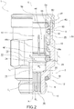
- The characteristics and advantages of the quick-fit connector according to the present invention will be evident from the description given below, by way of a nonlimiting example, according to the appended drawings, wherein:
- -
figure 1 shows a quick-fit connector according to one embodiment of the present invention; and -
figure 2 shows a partial cross-section view of the quick-fit connector infigure 1 . - With reference to the appended drawings, reference numeral 1 globally denotes a quick-fit connector for pneumatic systems, intended for connection to the free end of a pipe to a utility, such as a header, or to another pipe.
- The connector 1 comprises a main
tubular body 2 intended for connection with the utility or header. Themain body 2 extends along a straight body axis X, from a connection end 4, suitable to engage the utility or the other pipe, for example provided with anexternal thread 6, and anopposite end 8. - Preferably, at the connection end 4, for example alongside the
thread 6, themain body 2 has a first externalannular seat 10, in which afirst sealing ring 12 is housed, suitable to be subjected to axial compression when themain body 2 is screwed to the utility in a functional manner. - Internally, the
main body 2 has a throughcavity 14 between the connection end 4 and theopposite end 8. - The
cavity 14, at thethread 6 and preferably at the firstannular seat 10, has afirst compartment 16 having a predefined diameter D1 and a predefined axial length L1, such as to axially contain thethread 6 and the firstannular seat 10. - Preferably, the
compartment 16 is internally provided with a grooved profile, used to attach the connector to the utility. - In addition, the
cavity 14 comprises asecond compartment 18, axially alongside thefirst compartment 16, having a predefined diameter D2 and an axial length L2; thesecond compartment 18 has a smooth side surface. - The diameter D2 of the
second compartment 18 is greater than the diameter D1 of thefirst compartment 16, so as to form anaxial stop 20 to the pipe end inserted in the connector. - Said
axial stop 20 consists of a circular ring lying on an imaginary plane perpendicular to the body axis X. - The
cavity 14 further comprises athird compartment 22 axially alongside thesecond compartment 18, having a predetermined diameter D3 and axial length L3; preferably between thesecond compartment 18 andthird compartment 20 there is a slotted chamfer. - The diameter D3 of the
third compartment 22 is greater than the diameter D2 of thesecond compartment 18, so as to form anaxial support 24 for asecond sealing ring 26; saidaxial support 24 consists of a circular ring lying on an imaginary plane perpendicular to the body axis X. - Lastly, the
cavity 14 comprises aterminal compartment 28, alongside thethird compartment 22, which extends as far as theopposite end 8 and is annularly delimited by aside wall 30 of themain body 2. - The connector 1 further comprises a
pincer body 40 inserted in themain body 2, housed in theterminal compartment 28 and, preferably, at least in part, in thethird compartment 22. - Inserted in the
main body 2, thepincer body 40 is free to move axially in said main body, for a predefined and limited stroke. - The
pincer body 40 comprises aflexible portion 42, of a generally annular cylindrical shape, comprising a plurality ofpetals 44, side by side and separated circumferentially. - Internally, each
petal 44, in the vicinity of the free end next to thesecond sealing ring 26 comprises a retention prominence 48 projecting radially internally; the retention prominences 48, which are preferably aligned circumferentially, together form a retention ring of thepincer body 42, for retaining the end of the pipe inside the connector. - The retention prominences 48 simultaneously constitute a slotted chamfer to the insertion end of the pipe towards the
first compartment 18, a holding tooth that prevents the extraction of the pipe towards the outside of the connector and, dimensionally interfering with the outer diameter outside the pipe, forcing the opening of the flexible petal portion during the insertion of the pipe end. - Internally, the
side wall 30 has aprojection 49 projecting radially inwards. - On the side facing the
opposite end 8, theprojection 49 forms a slotted chamfer 49a which facilitates the insertion of thepincer body 40 in themain body 2 during the assembly of the connector; on the opposite side, facing towards thethird sealing ring 26, theprojection 49 has a frusto-conical surface 49b which forms a narrowing which, when the pipe connected to the connector is pulled outwards, interferes with the ends of thepetals 44, causing a clamping on said pipe, which prevents its extraction. - Preferably, moreover, the
pincer body 40 is provided with at least one external seal, which cooperates with themain body 2. - For example, the
pincer body 40 is externally provided with an annularouter sealing seat 50 in which athird sealing ring 52 is housed. Preferably, saidthird sealing ring 52 is radially compressed between theside wall 30 of themain body 2 and the side wall of thepincer body 40, creating a seal. - Additionally, preferably, the
pincer body 40 is also provided with an inner seal, intended to cooperate with the outer surface of the pipe end. - For example the
pincer body 40 has an annularinner sealing seat 50 in which afourth sealing ring 56 is housed, designed to be radially compressed to create a seal with the pipe. - The
pincer body 40 further comprises anannular base portion 58, from which, on the one hand, thepetals 44 of theflexible portion 42 axially extend and which, on the opposite side, protruding from the main body, engages with saidmain body 2 to prevent the entrance of dust, splinters and the like in theterminal compartment 28, in the interspace between thepincer body 40 and themain body 2. - When the
pincer body 40 is inserted into themain body 2, thebase portion 58 protrudes at least partly from theopposite end 8 of themain body 2 and theside wall 30 of themain body 2 extends axially so as to insert itself at least in part, in a sliding manner, in thebase portion 58, preventing access to theterminal compartment 28, in the interspace between thepincer body 40 and saidside wall 30. - Preferably, the
base portion 58 comprises anannular pocket 60, delimited radially outwards by anannular pocket wall 62, suitable to slidingly house a free end of theside wall 30. For example, thepocket wall 62 axially surmounts at least partially theside wall 30. - In one embodiment, the
pocket wall 62 has an axial extension such as not to radially overlap the portion of thepincer body 40 in which the annularouter sealing seat 50 is made in which thethird sealing ring 52 is housed. This way, in the production process of the connector, it is possible to make saidouter sealing seat 50 with a machine tool acting radially on the pincer body. - For example, the
pocket wall 62 ends at the level of, or just beyond, the internal step which delimits the annularinner sealing seat 54 for thefourth sealing ring 56. Radially overlapping the portion of the pincer body in which the annularinner sealing seat 54 is formed, in fact, it facilitates the gripping of the pincer body during the machining phase to make said annularinner sealing seat 54. Moreover, thepocket wall 62 comes to have an axial extension such as to ensure that it surmounts theside wall 30 of themain body 2 even when the pincer is in the retracted position. - Preferably, the
main body 2 of the connector 1 consists of a single piece, preferably of metal material, for example brass. Typically, the connector, when straight, is produced starting from a semi-finished bar, subsequently moulded by machine tooling. - According to further embodiments, the connector 1 is made of steel, for example stainless steel, or plastic material.
- Preferably, the pincer body is made of metal, typically starting from a semi-finished bar.
- Innovatively, the quick-fit connector according to the present invention satisfies the need to prevent the entrance of dust or splinters in the interspace between the pincer body and the main body, and is also easy and economical to produce. There are in fact no additional components compared to a traditional connector.
- It is clear that a person skilled in the art may make modifications to the quick-fit connector described above so as to satisfy contingent requirements ,all contained within the scope of protection as defined by the following claims.
Claims (11)
- Quick-fit connector (1) for a pipe of a pneumatic system, comprising- a main tubular body (2) in one piece, with a body axis (X), suitable for connecting to a utility or to a header; and- a pincer body (40) with a flexible portion (42) housed in a terminal compartment (28) of the main body (2), said flexible portion (42) being penetrable by the pipe and suitable to prevent its extraction, and with a base portion (58) projecting outside the main body (2);wherein the main body (2) comprises a side wall (30) slidingly insertable in the base portion (58) to prevent the entrance of dust, splinters and similar in the interspace of the terminal compartment (28) between the pincer body (40) and the main body (2), and wherein the pincer body (40) has externally, an annular outer sealing seat (50) in which a sealing ring (52) is housed, radially compressed between the side wall (30) of the main body (2) and the pincer body (40) in order to provide a seal.
- Connector according to claim 1, wherein the base portion (58) comprises an annular pocket (60), delimited radially outwards by an annular pocket wall (62), suitable to slidingly house a free end of the side wall (30) of the main body.
- Connector according to claim 2, wherein the pocket wall (62) axially surmounts at least partially the side wall (30) .
- Connector according to any of the preceding claims, wherein the pincer body (40) inserted in the main body (2) is free to move axially in a predetermined and limited stroke.
- Connector according to any of the preceding claims, wherein the side wall (30) has a projection (49) on the inside, projecting radially inwardly, suitable to engage the flexible portion (42).
- Connector according to any of the preceding claims, wherein the pincer body (40) has internally, an annular inner sealing seat (54) in which a further sealing ring (56) is housed, designed to be radially compressed to provide a seal with the pipe.
- Connector according to any of the preceding claims, wherein the main body (2) comprises, on the opposite side to the base portion (58) of the pincer body (40), a thread (6) .
- Connector according to claim 7, wherein the main body (2) has externally, alongside the thread (6), a first annular seat (10) in which a first sealing ring (12) is housed, suitable to be subjected to axial compression when the main body (2) is screwed to the utility in a functional manner.
- Connector according to claim 8, wherein the main body (2) has internally, an axial support (24) for a second sealing ring (26), against which the flexible portion (42) of the pincer body (40) abuts axially.
- Connector according to any of the previous claims, where the flexible portion (42) of the pincer body (40) comprises a plurality of petals (44) having an axial extension, supported and separated circumferentially.
- Connector according to claim 10, wherein each petal (44), near a free end, comprises a retention prominence (48) projecting radially inwards, which, together with the prominences (48) of the other petals (44), forms a ring for the retention of the end of the pipe inside the connector.
Applications Claiming Priority (2)
| Application Number | Priority Date | Filing Date | Title |
|---|---|---|---|
| ITUB2015A003891A ITUB20153891A1 (en) | 2015-09-25 | 2015-09-25 | QUICK FITTING FOR PNEUMATIC SYSTEMS |
| PCT/IB2016/055700 WO2017051369A1 (en) | 2015-09-25 | 2016-09-23 | Quick-fit connector for pneumatic equipment |
Publications (2)
| Publication Number | Publication Date |
|---|---|
| EP3353458A1 EP3353458A1 (en) | 2018-08-01 |
| EP3353458B1 true EP3353458B1 (en) | 2019-08-21 |
Family
ID=54884318
Family Applications (1)
| Application Number | Title | Priority Date | Filing Date |
|---|---|---|---|
| EP16794418.0A Active EP3353458B1 (en) | 2015-09-25 | 2016-09-23 | Quick-fit connector for pneumatic equipment |
Country Status (5)
| Country | Link |
|---|---|
| US (1) | US20180266603A1 (en) |
| EP (1) | EP3353458B1 (en) |
| CN (1) | CN108174609B (en) |
| IT (1) | ITUB20153891A1 (en) |
| WO (1) | WO2017051369A1 (en) |
Families Citing this family (2)
| Publication number | Priority date | Publication date | Assignee | Title |
|---|---|---|---|---|
| USD921855S1 (en) * | 2019-10-23 | 2021-06-08 | J.Juan S.A.U. | Connector for fluids |
| CN118103629A (en) * | 2021-10-05 | 2024-05-28 | 艾泽勒有限公司 | Connecting device for connecting pipe-shaped components |
Family Cites Families (22)
| Publication number | Priority date | Publication date | Assignee | Title |
|---|---|---|---|---|
| GB1602077A (en) * | 1978-05-31 | 1981-11-04 | Imi Enots Ltd | Tube coupling device |
| ES238468Y (en) * | 1978-10-02 | 1979-05-16 | PERFECTED QUICK COUPLING FOR PLASTIC PIPES. | |
| GB2132296B (en) * | 1982-12-13 | 1986-02-05 | Guest John Ltd | Tube coupling |
| DE3666623D1 (en) * | 1986-05-24 | 1989-11-30 | Voss Armaturen | Socketless fitting for a releasable connection of a synthetic conduit with a sealing gripping element |
| CN1014264B (en) * | 1988-03-17 | 1991-10-09 | 马克斯·帕斯布里希 | Detachable pipe and rod connector |
| DE3844421A1 (en) * | 1988-03-17 | 1989-09-28 | Max Pasbrig | DETACHABLE CONNECTING DEVICE FOR TUBES, HOSES, RODS OR THE LIKE |
| DE4002057A1 (en) * | 1989-08-03 | 1991-02-07 | Voss Armaturen | Plug-in fitment for detachable connecting pipes - consists of housing section with inner cone, collect and seal, with sealing lips and dirt seal |
| DE4115791C1 (en) * | 1991-05-10 | 1992-09-03 | Mannesmann Ag, 4000 Duesseldorf, De | |
| DE4223472A1 (en) * | 1992-07-16 | 1994-01-20 | Voss Armaturen | Push-in fitting for quick and detachable connection of pipes |
| DE69412912T2 (en) * | 1993-06-14 | 1999-03-25 | Aoi K.K., Gotenba, Shizuoka | Pipe connector |
| US5683120A (en) * | 1996-06-03 | 1997-11-04 | Parker-Hannifin Corporation | Releasable push-to-connect tube fitting |
| ES2145650B1 (en) * | 1996-07-19 | 2001-03-01 | Fico Transpar Sa | FAST CONNECTION AND DISCONNECTION DEVICE FOR ELECTRIC PUMPS AND DRIVES OF WASHING MACHINES OF MOTOR VEHICLES. |
| US5927975A (en) * | 1997-01-24 | 1999-07-27 | Esrock; Bernard S. | Fitting for dental syringe tip |
| US6224117B1 (en) * | 1998-10-05 | 2001-05-01 | Dana Corporation | Contaminant resistant tube fitting |
| IT1317161B1 (en) * | 2000-04-04 | 2003-05-27 | Camozzi S P A | QUICK CONNECTION DEVICE OF A TUBE TO A RIGID ELEMENT |
| US7506899B2 (en) * | 2003-03-20 | 2009-03-24 | Rain Bird Corporation | Multi-diameter tube fitting |
| US6988747B2 (en) * | 2003-03-20 | 2006-01-24 | Rain Bird Corporation | Multi-diameter tube coupling |
| US20090160179A1 (en) * | 2003-05-29 | 2009-06-25 | Ericksen Kent C | Coupling release mechanism for irrigation system |
| WO2005001326A1 (en) * | 2003-06-23 | 2005-01-06 | Lincoln Gmbh & Co. Kg | Connecting device for a pipe or similar |
| US10480698B2 (en) * | 2014-09-19 | 2019-11-19 | Kongsberg Automotive As | Tube connector |
| CN204387552U (en) * | 2014-12-03 | 2015-06-10 | 浙江超润润滑元件有限公司 | The fast inserting structure of pipe joint |
| DE102017004982A1 (en) * | 2017-05-16 | 2018-11-22 | Eisele Pneumatics Gmbh & Co. Kg | connection device |
-
2015
- 2015-09-25 IT ITUB2015A003891A patent/ITUB20153891A1/en unknown
-
2016
- 2016-09-23 WO PCT/IB2016/055700 patent/WO2017051369A1/en not_active Ceased
- 2016-09-23 US US15/762,390 patent/US20180266603A1/en not_active Abandoned
- 2016-09-23 CN CN201680055500.2A patent/CN108174609B/en active Active
- 2016-09-23 EP EP16794418.0A patent/EP3353458B1/en active Active
Non-Patent Citations (1)
| Title |
|---|
| None * |
Also Published As
| Publication number | Publication date |
|---|---|
| ITUB20153891A1 (en) | 2017-03-25 |
| WO2017051369A1 (en) | 2017-03-30 |
| US20180266603A1 (en) | 2018-09-20 |
| EP3353458A1 (en) | 2018-08-01 |
| CN108174609A (en) | 2018-06-15 |
| CN108174609B (en) | 2019-11-05 |
Similar Documents
| Publication | Publication Date | Title |
|---|---|---|
| EP2284430B1 (en) | One-touch joint for piping | |
| US6179347B1 (en) | Snap-action pipe coupling retainer with a rhomboidal cross-section | |
| US5934854A (en) | Ring fastener, apparatus for installing same, and installation method for the ring fastener | |
| GB2180313A (en) | A releasable plug-in joint | |
| EP3430299B1 (en) | Push-to-connect fitting device, arrangement and method | |
| US3948548A (en) | Hose and pipe coupling | |
| JP4644063B2 (en) | Pipe connection structure | |
| US9909701B2 (en) | Tube couplings | |
| EP3688359B1 (en) | Fitting and method of forming a fitting conduit | |
| CN103213093A (en) | An assembling method of an annular workpiece and an assembling clamp | |
| KR960023979A (en) | Tube joint | |
| US20150300541A1 (en) | Coupling connection for corrugated pipes | |
| KR20130084246A (en) | Spring band clip | |
| WO2016014772A1 (en) | Integrated piping conduit with adaptor device and method | |
| US20180266603A1 (en) | Quick-fit connector for pneumatic equipment | |
| EP1596118B1 (en) | Dustproof cap for quick connector and quick connector | |
| JP2009270606A (en) | Pipe joint manufacturing method | |
| JP2014190522A (en) | Pipe joint, seal ring for pipe joint and method for connecting pipe joint to pipe | |
| JP2021050748A (en) | Pipe joint and pipe removal method | |
| EP2752609A1 (en) | Plug for connector | |
| ITMI940488A1 (en) | COUPLING JOINT FOR PIPE AND / OR FLEXIBLE CONDUCT | |
| EP2966332B1 (en) | Drain valve for a pressurised fluid tank and pressurised fluid tank comprising the same | |
| JP4229685B2 (en) | Connector for small diameter pipe connection | |
| JP2016538489A (en) | Quick coupling | |
| KR101478923B1 (en) | Quick Connector |
Legal Events
| Date | Code | Title | Description |
|---|---|---|---|
| STAA | Information on the status of an ep patent application or granted ep patent |
Free format text: STATUS: UNKNOWN |
|
| STAA | Information on the status of an ep patent application or granted ep patent |
Free format text: STATUS: THE INTERNATIONAL PUBLICATION HAS BEEN MADE |
|
| PUAI | Public reference made under article 153(3) epc to a published international application that has entered the european phase |
Free format text: ORIGINAL CODE: 0009012 |
|
| STAA | Information on the status of an ep patent application or granted ep patent |
Free format text: STATUS: REQUEST FOR EXAMINATION WAS MADE |
|
| 17P | Request for examination filed |
Effective date: 20180221 |
|
| AK | Designated contracting states |
Kind code of ref document: A1 Designated state(s): AL AT BE BG CH CY CZ DE DK EE ES FI FR GB GR HR HU IE IS IT LI LT LU LV MC MK MT NL NO PL PT RO RS SE SI SK SM TR |
|
| AX | Request for extension of the european patent |
Extension state: BA ME |
|
| DAV | Request for validation of the european patent (deleted) | ||
| DAX | Request for extension of the european patent (deleted) | ||
| GRAP | Despatch of communication of intention to grant a patent |
Free format text: ORIGINAL CODE: EPIDOSNIGR1 |
|
| STAA | Information on the status of an ep patent application or granted ep patent |
Free format text: STATUS: GRANT OF PATENT IS INTENDED |
|
| INTG | Intention to grant announced |
Effective date: 20190329 |
|
| GRAS | Grant fee paid |
Free format text: ORIGINAL CODE: EPIDOSNIGR3 |
|
| GRAA | (expected) grant |
Free format text: ORIGINAL CODE: 0009210 |
|
| STAA | Information on the status of an ep patent application or granted ep patent |
Free format text: STATUS: THE PATENT HAS BEEN GRANTED |
|
| AK | Designated contracting states |
Kind code of ref document: B1 Designated state(s): AL AT BE BG CH CY CZ DE DK EE ES FI FR GB GR HR HU IE IS IT LI LT LU LV MC MK MT NL NO PL PT RO RS SE SI SK SM TR |
|
| REG | Reference to a national code |
Ref country code: GB Ref legal event code: FG4D |
|
| REG | Reference to a national code |
Ref country code: CH Ref legal event code: EP |
|
| REG | Reference to a national code |
Ref country code: DE Ref legal event code: R096 Ref document number: 602016019152 Country of ref document: DE |
|
| REG | Reference to a national code |
Ref country code: AT Ref legal event code: REF Ref document number: 1170156 Country of ref document: AT Kind code of ref document: T Effective date: 20190915 |
|
| REG | Reference to a national code |
Ref country code: IE Ref legal event code: FG4D |
|
| REG | Reference to a national code |
Ref country code: CH Ref legal event code: PK Free format text: BERICHTIGUNGEN |
|
| RAP2 | Party data changed (patent owner data changed or rights of a patent transferred) |
Owner name: CAMOZZI AUTOMATION S.P.A. |
|
| RIN2 | Information on inventor provided after grant (corrected) |
Inventor name: GNUTTI, GIANLUCA Inventor name: CAMOZZI, GEROMINO |
|
| REG | Reference to a national code |
Ref country code: LT Ref legal event code: MG4D |
|
| REG | Reference to a national code |
Ref country code: NL Ref legal event code: MP Effective date: 20190821 |
|
| PG25 | Lapsed in a contracting state [announced via postgrant information from national office to epo] |
Ref country code: PT Free format text: LAPSE BECAUSE OF FAILURE TO SUBMIT A TRANSLATION OF THE DESCRIPTION OR TO PAY THE FEE WITHIN THE PRESCRIBED TIME-LIMIT Effective date: 20191223 Ref country code: NO Free format text: LAPSE BECAUSE OF FAILURE TO SUBMIT A TRANSLATION OF THE DESCRIPTION OR TO PAY THE FEE WITHIN THE PRESCRIBED TIME-LIMIT Effective date: 20191121 Ref country code: NL Free format text: LAPSE BECAUSE OF FAILURE TO SUBMIT A TRANSLATION OF THE DESCRIPTION OR TO PAY THE FEE WITHIN THE PRESCRIBED TIME-LIMIT Effective date: 20190821 Ref country code: BG Free format text: LAPSE BECAUSE OF FAILURE TO SUBMIT A TRANSLATION OF THE DESCRIPTION OR TO PAY THE FEE WITHIN THE PRESCRIBED TIME-LIMIT Effective date: 20191121 Ref country code: LT Free format text: LAPSE BECAUSE OF FAILURE TO SUBMIT A TRANSLATION OF THE DESCRIPTION OR TO PAY THE FEE WITHIN THE PRESCRIBED TIME-LIMIT Effective date: 20190821 Ref country code: HR Free format text: LAPSE BECAUSE OF FAILURE TO SUBMIT A TRANSLATION OF THE DESCRIPTION OR TO PAY THE FEE WITHIN THE PRESCRIBED TIME-LIMIT Effective date: 20190821 Ref country code: SE Free format text: LAPSE BECAUSE OF FAILURE TO SUBMIT A TRANSLATION OF THE DESCRIPTION OR TO PAY THE FEE WITHIN THE PRESCRIBED TIME-LIMIT Effective date: 20190821 Ref country code: FI Free format text: LAPSE BECAUSE OF FAILURE TO SUBMIT A TRANSLATION OF THE DESCRIPTION OR TO PAY THE FEE WITHIN THE PRESCRIBED TIME-LIMIT Effective date: 20190821 |
|
| PG25 | Lapsed in a contracting state [announced via postgrant information from national office to epo] |
Ref country code: AL Free format text: LAPSE BECAUSE OF FAILURE TO SUBMIT A TRANSLATION OF THE DESCRIPTION OR TO PAY THE FEE WITHIN THE PRESCRIBED TIME-LIMIT Effective date: 20190821 Ref country code: ES Free format text: LAPSE BECAUSE OF FAILURE TO SUBMIT A TRANSLATION OF THE DESCRIPTION OR TO PAY THE FEE WITHIN THE PRESCRIBED TIME-LIMIT Effective date: 20190821 Ref country code: GR Free format text: LAPSE BECAUSE OF FAILURE TO SUBMIT A TRANSLATION OF THE DESCRIPTION OR TO PAY THE FEE WITHIN THE PRESCRIBED TIME-LIMIT Effective date: 20191122 Ref country code: IS Free format text: LAPSE BECAUSE OF FAILURE TO SUBMIT A TRANSLATION OF THE DESCRIPTION OR TO PAY THE FEE WITHIN THE PRESCRIBED TIME-LIMIT Effective date: 20191221 Ref country code: RS Free format text: LAPSE BECAUSE OF FAILURE TO SUBMIT A TRANSLATION OF THE DESCRIPTION OR TO PAY THE FEE WITHIN THE PRESCRIBED TIME-LIMIT Effective date: 20190821 Ref country code: LV Free format text: LAPSE BECAUSE OF FAILURE TO SUBMIT A TRANSLATION OF THE DESCRIPTION OR TO PAY THE FEE WITHIN THE PRESCRIBED TIME-LIMIT Effective date: 20190821 |
|
| REG | Reference to a national code |
Ref country code: AT Ref legal event code: MK05 Ref document number: 1170156 Country of ref document: AT Kind code of ref document: T Effective date: 20190821 |
|
| PG25 | Lapsed in a contracting state [announced via postgrant information from national office to epo] |
Ref country code: TR Free format text: LAPSE BECAUSE OF FAILURE TO SUBMIT A TRANSLATION OF THE DESCRIPTION OR TO PAY THE FEE WITHIN THE PRESCRIBED TIME-LIMIT Effective date: 20190821 |
|
| PG25 | Lapsed in a contracting state [announced via postgrant information from national office to epo] |
Ref country code: RO Free format text: LAPSE BECAUSE OF FAILURE TO SUBMIT A TRANSLATION OF THE DESCRIPTION OR TO PAY THE FEE WITHIN THE PRESCRIBED TIME-LIMIT Effective date: 20190821 Ref country code: AT Free format text: LAPSE BECAUSE OF FAILURE TO SUBMIT A TRANSLATION OF THE DESCRIPTION OR TO PAY THE FEE WITHIN THE PRESCRIBED TIME-LIMIT Effective date: 20190821 Ref country code: DK Free format text: LAPSE BECAUSE OF FAILURE TO SUBMIT A TRANSLATION OF THE DESCRIPTION OR TO PAY THE FEE WITHIN THE PRESCRIBED TIME-LIMIT Effective date: 20190821 Ref country code: PL Free format text: LAPSE BECAUSE OF FAILURE TO SUBMIT A TRANSLATION OF THE DESCRIPTION OR TO PAY THE FEE WITHIN THE PRESCRIBED TIME-LIMIT Effective date: 20190821 Ref country code: EE Free format text: LAPSE BECAUSE OF FAILURE TO SUBMIT A TRANSLATION OF THE DESCRIPTION OR TO PAY THE FEE WITHIN THE PRESCRIBED TIME-LIMIT Effective date: 20190821 |
|
| PG25 | Lapsed in a contracting state [announced via postgrant information from national office to epo] |
Ref country code: IS Free format text: LAPSE BECAUSE OF FAILURE TO SUBMIT A TRANSLATION OF THE DESCRIPTION OR TO PAY THE FEE WITHIN THE PRESCRIBED TIME-LIMIT Effective date: 20200224 Ref country code: SK Free format text: LAPSE BECAUSE OF FAILURE TO SUBMIT A TRANSLATION OF THE DESCRIPTION OR TO PAY THE FEE WITHIN THE PRESCRIBED TIME-LIMIT Effective date: 20190821 Ref country code: MC Free format text: LAPSE BECAUSE OF FAILURE TO SUBMIT A TRANSLATION OF THE DESCRIPTION OR TO PAY THE FEE WITHIN THE PRESCRIBED TIME-LIMIT Effective date: 20190821 Ref country code: SM Free format text: LAPSE BECAUSE OF FAILURE TO SUBMIT A TRANSLATION OF THE DESCRIPTION OR TO PAY THE FEE WITHIN THE PRESCRIBED TIME-LIMIT Effective date: 20190821 Ref country code: CZ Free format text: LAPSE BECAUSE OF FAILURE TO SUBMIT A TRANSLATION OF THE DESCRIPTION OR TO PAY THE FEE WITHIN THE PRESCRIBED TIME-LIMIT Effective date: 20190821 |
|
| REG | Reference to a national code |
Ref country code: CH Ref legal event code: PL |
|
| REG | Reference to a national code |
Ref country code: DE Ref legal event code: R097 Ref document number: 602016019152 Country of ref document: DE |
|
| PLBE | No opposition filed within time limit |
Free format text: ORIGINAL CODE: 0009261 |
|
| STAA | Information on the status of an ep patent application or granted ep patent |
Free format text: STATUS: NO OPPOSITION FILED WITHIN TIME LIMIT |
|
| PG2D | Information on lapse in contracting state deleted |
Ref country code: IS |
|
| PG25 | Lapsed in a contracting state [announced via postgrant information from national office to epo] |
Ref country code: CH Free format text: LAPSE BECAUSE OF NON-PAYMENT OF DUE FEES Effective date: 20190930 Ref country code: IE Free format text: LAPSE BECAUSE OF NON-PAYMENT OF DUE FEES Effective date: 20190923 Ref country code: LU Free format text: LAPSE BECAUSE OF NON-PAYMENT OF DUE FEES Effective date: 20190923 Ref country code: LI Free format text: LAPSE BECAUSE OF NON-PAYMENT OF DUE FEES Effective date: 20190930 |
|
| REG | Reference to a national code |
Ref country code: BE Ref legal event code: MM Effective date: 20190930 |
|
| 26N | No opposition filed |
Effective date: 20200603 |
|
| PG25 | Lapsed in a contracting state [announced via postgrant information from national office to epo] |
Ref country code: SI Free format text: LAPSE BECAUSE OF FAILURE TO SUBMIT A TRANSLATION OF THE DESCRIPTION OR TO PAY THE FEE WITHIN THE PRESCRIBED TIME-LIMIT Effective date: 20190821 Ref country code: BE Free format text: LAPSE BECAUSE OF NON-PAYMENT OF DUE FEES Effective date: 20190930 |
|
| PG25 | Lapsed in a contracting state [announced via postgrant information from national office to epo] |
Ref country code: CY Free format text: LAPSE BECAUSE OF FAILURE TO SUBMIT A TRANSLATION OF THE DESCRIPTION OR TO PAY THE FEE WITHIN THE PRESCRIBED TIME-LIMIT Effective date: 20190821 |
|
| PG25 | Lapsed in a contracting state [announced via postgrant information from national office to epo] |
Ref country code: MT Free format text: LAPSE BECAUSE OF FAILURE TO SUBMIT A TRANSLATION OF THE DESCRIPTION OR TO PAY THE FEE WITHIN THE PRESCRIBED TIME-LIMIT Effective date: 20190821 Ref country code: HU Free format text: LAPSE BECAUSE OF FAILURE TO SUBMIT A TRANSLATION OF THE DESCRIPTION OR TO PAY THE FEE WITHIN THE PRESCRIBED TIME-LIMIT; INVALID AB INITIO Effective date: 20160923 |
|
| PG25 | Lapsed in a contracting state [announced via postgrant information from national office to epo] |
Ref country code: MK Free format text: LAPSE BECAUSE OF FAILURE TO SUBMIT A TRANSLATION OF THE DESCRIPTION OR TO PAY THE FEE WITHIN THE PRESCRIBED TIME-LIMIT Effective date: 20190821 |
|
| P01 | Opt-out of the competence of the unified patent court (upc) registered |
Effective date: 20230525 |
|
| PGFP | Annual fee paid to national office [announced via postgrant information from national office to epo] |
Ref country code: DE Payment date: 20250923 Year of fee payment: 10 |
|
| PGFP | Annual fee paid to national office [announced via postgrant information from national office to epo] |
Ref country code: IT Payment date: 20250725 Year of fee payment: 10 |
|
| PGFP | Annual fee paid to national office [announced via postgrant information from national office to epo] |
Ref country code: GB Payment date: 20250919 Year of fee payment: 10 |
|
| PGFP | Annual fee paid to national office [announced via postgrant information from national office to epo] |
Ref country code: FR Payment date: 20250829 Year of fee payment: 10 |