EP3352549A1 - Cooling device for electronic apparatus - Google Patents
Cooling device for electronic apparatus Download PDFInfo
- Publication number
- EP3352549A1 EP3352549A1 EP16855140.6A EP16855140A EP3352549A1 EP 3352549 A1 EP3352549 A1 EP 3352549A1 EP 16855140 A EP16855140 A EP 16855140A EP 3352549 A1 EP3352549 A1 EP 3352549A1
- Authority
- EP
- European Patent Office
- Prior art keywords
- heat sink
- cooling air
- cooling
- mist
- heat
- Prior art date
- Legal status (The legal status is an assumption and is not a legal conclusion. Google has not performed a legal analysis and makes no representation as to the accuracy of the status listed.)
- Granted
Links
Images



Classifications
-
- H—ELECTRICITY
- H05—ELECTRIC TECHNIQUES NOT OTHERWISE PROVIDED FOR
- H05K—PRINTED CIRCUITS; CASINGS OR CONSTRUCTIONAL DETAILS OF ELECTRIC APPARATUS; MANUFACTURE OF ASSEMBLAGES OF ELECTRICAL COMPONENTS
- H05K7/00—Constructional details common to different types of electric apparatus
- H05K7/20—Modifications to facilitate cooling, ventilating, or heating
- H05K7/2089—Modifications to facilitate cooling, ventilating, or heating for power electronics, e.g. for inverters for controlling motor
- H05K7/20909—Forced ventilation, e.g. on heat dissipaters coupled to components
-
- H—ELECTRICITY
- H05—ELECTRIC TECHNIQUES NOT OTHERWISE PROVIDED FOR
- H05K—PRINTED CIRCUITS; CASINGS OR CONSTRUCTIONAL DETAILS OF ELECTRIC APPARATUS; MANUFACTURE OF ASSEMBLAGES OF ELECTRICAL COMPONENTS
- H05K7/00—Constructional details common to different types of electric apparatus
- H05K7/20—Modifications to facilitate cooling, ventilating, or heating
- H05K7/2089—Modifications to facilitate cooling, ventilating, or heating for power electronics, e.g. for inverters for controlling motor
- H05K7/20909—Forced ventilation, e.g. on heat dissipaters coupled to components
- H05K7/20918—Forced ventilation, e.g. on heat dissipaters coupled to components the components being isolated from air flow, e.g. hollow heat sinks, wind tunnels or funnels
-
- B—PERFORMING OPERATIONS; TRANSPORTING
- B64—AIRCRAFT; AVIATION; COSMONAUTICS
- B64C—AEROPLANES; HELICOPTERS
- B64C25/00—Alighting gear
- B64C25/32—Alighting gear characterised by elements which contact the ground or similar surface
- B64C25/34—Alighting gear characterised by elements which contact the ground or similar surface wheeled type, e.g. multi-wheeled bogies
- B64C25/36—Arrangements or adaptations of wheels, tyres or axles in general
-
- H—ELECTRICITY
- H05—ELECTRIC TECHNIQUES NOT OTHERWISE PROVIDED FOR
- H05K—PRINTED CIRCUITS; CASINGS OR CONSTRUCTIONAL DETAILS OF ELECTRIC APPARATUS; MANUFACTURE OF ASSEMBLAGES OF ELECTRICAL COMPONENTS
- H05K7/00—Constructional details common to different types of electric apparatus
- H05K7/20—Modifications to facilitate cooling, ventilating, or heating
- H05K7/2039—Modifications to facilitate cooling, ventilating, or heating characterised by the heat transfer by conduction from the heat generating element to a dissipating body
-
- H—ELECTRICITY
- H05—ELECTRIC TECHNIQUES NOT OTHERWISE PROVIDED FOR
- H05K—PRINTED CIRCUITS; CASINGS OR CONSTRUCTIONAL DETAILS OF ELECTRIC APPARATUS; MANUFACTURE OF ASSEMBLAGES OF ELECTRICAL COMPONENTS
- H05K7/00—Constructional details common to different types of electric apparatus
- H05K7/20—Modifications to facilitate cooling, ventilating, or heating
- H05K7/2089—Modifications to facilitate cooling, ventilating, or heating for power electronics, e.g. for inverters for controlling motor
- H05K7/20936—Liquid coolant with phase change
-
- H—ELECTRICITY
- H05—ELECTRIC TECHNIQUES NOT OTHERWISE PROVIDED FOR
- H05K—PRINTED CIRCUITS; CASINGS OR CONSTRUCTIONAL DETAILS OF ELECTRIC APPARATUS; MANUFACTURE OF ASSEMBLAGES OF ELECTRICAL COMPONENTS
- H05K7/00—Constructional details common to different types of electric apparatus
- H05K7/20—Modifications to facilitate cooling, ventilating, or heating
- H05K7/20009—Modifications to facilitate cooling, ventilating, or heating using a gaseous coolant in electronic enclosures
- H05K7/20136—Forced ventilation, e.g. by fans
- H05K7/20172—Fan mounting or fan specifications
-
- H—ELECTRICITY
- H05—ELECTRIC TECHNIQUES NOT OTHERWISE PROVIDED FOR
- H05K—PRINTED CIRCUITS; CASINGS OR CONSTRUCTIONAL DETAILS OF ELECTRIC APPARATUS; MANUFACTURE OF ASSEMBLAGES OF ELECTRICAL COMPONENTS
- H05K7/00—Constructional details common to different types of electric apparatus
- H05K7/20—Modifications to facilitate cooling, ventilating, or heating
- H05K7/2029—Modifications to facilitate cooling, ventilating, or heating using a liquid coolant with phase change in electronic enclosures
- H05K7/20345—Sprayers; Atomizers
Definitions
- the present disclosure relates , to a cooling device for cooling an electronic device such as a power electronics-based device.
- cooling device for electronic device
- FIG. 1 The configuration of a conventional cooling device for electronic device (hereinafter referred to as "cooling device" for convenience of explanation) is explained below (see Patent Literature 1).
- a conventional cooling device typically includes a heat sink (radiator) that is connected in a heat-conductive manner to an electronic device.
- the heat sink is constituted by a material having an excellent thermal conductivity, such as aluminum alloy, and includes a plurality of heat radiating fins capable of heat radiation (to radiate heat) .
- the cooling device includes a blower, such as a fan, that causes cooling air to flow from an inlet toward an outlet of the heat sink.
- the blower causes, while the electronic device is being operated, the cooling air to flow from the inlet of the heat sink toward the outlet of the heat sink.
- the heat generated by driving of the electronic device is transmitted to the heat sink and then radiated to the cooling air from the heat radiating fins.
- Patent Literature 2 discloses a background art related to the present disclosure.
- the disclosed refrigerant circulating type cooling device is constituted by connecting a cooling plate, which cools a semiconductor element that is a high temperature heating element of the electronic device, a condenser installed outside an aircraft, and a refrigerant pump.
- the amount of heat generated by an electronic device tends to increase following an increase in the performance of the electronic device, and as a result, sufficiently increasing the radiation performance of a heat sink, in other words, the cooling performance of a cooling device is necessary. Therefore, usually, the heat transfer coefficient between the heat sink and the cooling air is increased by employing measures such as forming the heat radiating fins in a complex shape or increasing the number of the heat radiating fins. On the other hand, if such measures are employed on the heat sink, the pressure loss in the heat sink increases, resulting in upsizing of the blower and an increase in the energy consumption required for blowing the air.
- an object of the present disclosure is to provide a cooling device for electronic device that can solve the above-mentioned problems.
- a cooling device for an electronic device includes a heat sink that is in thermal contact with the electronic device; and a mist supplier that supplies mist to the heat sink and that is arranged upstream of the heat sink in a flow direction of cooling air passing via the heat sink.
- a cooling device for electronic device that can sufficiently increase the cooling performance while suppressing the upsizing of the blower and the increase in the energy consumption required for blowing the air can be provided.
- the term “arrange / arranged” refers to a case in which a structural component is directly arranged and also refers to a case in which a structural component is indirectly arranged via another member.
- the term “include / included” refers to a case in which a structural member is directly included and also refers to a case in which a structural component is indirectly included via another member.
- the term “downstream” refers to downstream in a flow direction of cooling air, and “upstream” refers to upstream in the flow direction of the cooling air.
- a reference letter “F” denotes the flow direction of the cooling air
- a reference letter “P” denotes a direction orthogonal to the flow direction of the cooling air
- a reference letter “U” denotes an upward direction (upward in the vertical direction)
- a reference letter “D” denotes a downward direction (downward in the vertical direction).
- a cooling device for electronic device (hereinafter referred to as "cooling device” for convenience of explanation) 10 according to an embodiment of the present disclosure is a device that cools motor drivers 12 and 42.
- the cooling device 10 is installed, for example, on a floor 14a of an engine room 14 of an aircraft.
- the motor driver 12 that is to be cooled is an example of a power electronics-based device installed in the aircraft.
- the motor driver 12 is a driver that drives a not-shown taxiing motor that causes not-shown wheels of the aircraft to rotate.
- the cooling device 10 includes a heat sink 16.
- the heat sink 16 is installed, for example, on the floor 14a of the engine room 14 by using a plurality of struts 18.
- the heat sink 16 is constituted by, for example, a material with an excellent thermal conductivity such as aluminum or aluminum alloy.
- the heat sink 16 includes a base (heat sink base) 20 formed in a square pipe-like shape.
- the base 20 includes a cooling passage 22 that is formed on the inner side of (inside) the base 20. Air from a passenger cabin flows into the cooling passage 22 as cooling air CA.
- the base 20 is connected in a heat-conductive manner to the motor driver 12. In other words, at the base 20, the heat sink 16 is in thermal contact with the motor driver 12.
- the motor driver 12 is installed on a lower outer surface 20a of the base 20 of the heat sink 16.
- the base 20 has a plurality of first heat radiating fins 24 arranged on a lower inner surface 20b thereof.
- the first heat radiating fins 24 are arranged at intervals in a direction P orthogonal to a flow direction F of the cooling air CA.
- the first heat radiating fin 24 is formed in a plate shape and extends in the flow direction F of the cooling air CA.
- the heat sink base 20 includes a plurality of second heat radiating fins 26 installed on an upper inner surface 20c in the base 20.
- the second heat radiating fins 26 are arranged at intervals alternately with the first heat radiating fins 24 in the direction P.
- the second heat radiating fin 26 is formed in a plate shape and extends in the flow direction F of the cooling air CA.
- first heat radiating fins 24 and the second heat radiating fins 26 can be formed in the form of a pin that extends in an upward direction U or a downward direction D. If formed so, the first heat radiating fins 24 and the second heat radiating fins 26 are arranged at intervals in the direction F and the direction P, respectively.
- the second heat radiating fins 26 can be omitted from the configuration of the heat sink 16.
- the heat sink 16 instead of the struts 18, the heat sink 16 can be installed on the floor of the engine room 14 by using other supporting units such as a pedestal.
- the heat sink 16 includes on downstream thereof a collecting duct 28 that collects the cooling air CA.
- the collecting duct 28 communicates with the cooling passage 22 of the heat sink 16.
- the collecting duct 28 includes on downstream thereof an air outlet 30 that sends the cooling air CA outside.
- the cooling device 10 includes a compressor (electric compressor) 32 arranged downstream of the heat sink 16 for sucking and compressing the cooling air CA.
- the compressor 32 is installed on the floor 14a of the engine room 14 by using a plurality of struts 34.
- the compressor 32 is an example of a blower that causes the cooling air CA to flow from an inlet toward an outlet of the cooling passage 22 of the heat sink 16.
- the compressor 32 includes a compressor housing 36, an impeller 38 that is rotatably arranged in the compressor housing 36, and a compressor motor 40 arranged in the compressor housing 36 and that rotates the impeller 38.
- the compressor motor 40 is driven by the motor driver 42.
- the motor driver 42 is connected in a heat-conductive manner to the heat sink 16. In other words, at the base 20, the heat sink 16 is in thermal contact with the motor driver 42.
- the motor driver 42 is installed on an upper outer surface 20d of the base 20 of the heat sink 16.
- the compressor housing 36 includes an air inlet 44 that is arranged upstream of the impeller 38 and that takes in the cooling air CA.
- the air inlet 44 communicates with the air outlet 30 via a coupling 46.
- the compressor housing 36 includes a spiral scroll flow path 48 that is arranged downstream of the impeller 38 in the compressor housing 36 and that collects the compressed cooling air CA.
- the compressor housing 36 includes arranged on the peripheral side thereof an air discharging port 50 for discharging the compressed cooling air CA.
- the air discharging port 50 communicates with the outside of the aircraft via a not-shown discharge pipe.
- the electric compressor 32 can be installed on the floor 14a of the engine room 14 by using other supporting units such as a pedestal.
- the cooling device 10 includes, in the flow direction F of the cooling air CA that passes via the heat sink 16, a mist supplier 52 arranged upstream of the heat sink 16.
- the mist supplier 52 supplies mist M to the cooling passage 22 of the heat sink 16 by using ultrasonic waves and the like.
- the mist supplier 52 is installed on the floor 14a of the engine room 14 by using a plurality of struts 54.
- the main constituent (ingredient) of the mist M is, for example, water.
- the mist supplier 52 includes a storage tank (for example, a water tank) 56 that stores the ingredient (for example, water W) of the mist M.
- the storage tank 56 is installed on the floor 14a of the engine room 14 by using the struts 54.
- the storage tank 56 is connected to a tank 58 installed at an appropriate position in the engine room 14 for maintaining the level of the water W in the storage tank 56 at a predetermined water level or higher.
- a piezoelectric vibrator an example of a vibrator
- the piezoelectric vibrator 60 is electrically connected to a driver circuit 62 installed at an appropriate position in the engine room 14. Upon receiving a high-frequency voltage from the driver circuit 62, the piezoelectric vibrator 60 vibrates, transmits (generates) the ultrasonic waves toward the surface of the water W stored in the storage tank 56, and atomizes the water W.
- the storage tank 56 includes a first connecting member 64 arranged upstream (on a side away from the heat sink 16) at the top of the storage tank 56.
- the first connecting member 64 is formed in, for example, a square pipe-like shape and includes internally (inside) an introduction passage 66.
- the introduction passage 66 introduces the cooling air CA to a space inside the storage tank 56.
- the storage tank 56 includes a second connecting member 68 arranged downstream (on a side near the heat sink 16) at the top of the storage tank 56.
- the second connecting member 68 is formed in, for example, a square pipe-like shape, and includes internally a lead-out passage 70.
- the lead-out passage 70 sends out from the space inside the storage tank 56 the cooling air CA which includes the mist M.
- the mist supplier 52 includes an introduction duct 72 arranged between an upper part of the first connecting member 64 and an upper part of the second connecting member 68.
- the introduction duct 72 introduces to the cooling passage 22 of the heat sink 16 the cooling air CA that includes the water mist M.
- the introduction duct 72 internally communicates with the introduction passage 66 of the first connecting member 64 on an inlet side thereof.
- the introduction duct 72 internally communicates with the lead-out passage 70 of the second connecting member 68 on an outlet side thereof.
- the introduction duct 72 includes arranged in the middle thereof (that is, between a portion connected to the introduction passage 66 and a portion connected to the lead-out passage 70) an adjusting plate (baffle plate) 74.
- the adjusting plate 74 has a plurality of through-holes 76 via which the cooling air CA passes, and is constituted by, for example, a perforated metal.
- the adjusting plate 74 arranged in the introduction duct 72 adjusts a flow rate of the cooling air CA to be introduced to the introduction passage 66 of the first connecting member 64.
- the adjusting plate 74 leads to the introduction passage 66 a part of the cooling air CA flown in from an inlet of the introduction duct 72, and leads out the remaining cooling air CA directly toward an outlet of the introduction duct 72 without passing via the storage tank 56.
- the mist supplier 52 includes a generating source for the mist M (hereinafter referred to as a mist generating source) 53 (see FIG. 3 ) and two flow paths that share an inlet of the cooling air CA and an outlet of the cooling air CA that flows towards the heat sink 16 (the cooling passage 22).
- the mist generating source 53 includes the storage tank 56 and the piezoelectric vibrator 60.
- One of the two flow paths (a first flow path: the introduction passage 66, the storage tank 56, and the lead-out passage 70) passes via the mist generating source 53, and the other flow path (a second flow path: the introduction duct 72) does not pass via the mist generating source 53.
- the adjusting plate 74 explained above is arranged between a branching point and a confluence point thereof from and to the first flow path, and the adjusting plate 74 adjusts the flow rate of the cooling air CA that flows via each flow path.
- the introduction duct 72 can internally include on the inlet side thereof a not-shown throttle.
- the mist supplier 52 (the storage tank 56) can be installed on the floor 14a of the engine room 14 by using other supporting units such as a pedestal.
- the introduction duct 72 includes upstream thereof a filter 78 that cleans the cooling air CA.
- a mixing duct 80 arranged between the introduction duct 72 and the heat sink 16 facilitates mixing of the cooling air CA and the mist M.
- An inlet arranged inside the mixing duct 80 communicates with the outlet arranged inside the introduction duct 72.
- An outlet arranged inside the mixing duct 80 communicates with the inlet of the cooling passage 22 of the heat sink 16 (inside of the heat sink 16).
- intermediate members such as a connecting pipe can be interposed between the introduction duct 72 and the filter 78.
- the compressor 32 sucks and compresses the cooling air CA. Then, suction action of the compressor 32 causes the cooling air CA to flow from the inlet toward the outlet of the cooling passage 22 of the heat sink 16 via the filter 78, the introduction duct 72, and the like.
- the heat generated by the operation of the motor driver 12 of the taxiing motor is transmitted to the heat sink 16 and then radiated to the cooling air CA via the first heat radiating fins 24, the heat sink base 20, and the like.
- the heat generated by the operation of the motor driver 42 of the compressor motor 40 is transmitted to the heat sink 16 and then radiated to the cooling air CA via the second heat radiating fins 26, the heat sink base 20, and the like.
- the compressor 32 After receiving the heat generated by the motor drivers 12 and 42, the compressor 32 sucks and compresses the cooling air CA, and then discharges the same to the outside of the aircraft via the air discharging port 50.
- the driver circuit 62 supplies a high-frequency voltage to the piezoelectric vibrator 60.
- the piezoelectric vibrator 60 vibrates and transmits the ultrasonic waves toward the surface of the water W in the storage tank 56.
- the mist M is generated from the surface of the water W in the storage tank 56. Inside the storage tank 56, the generated mist M mixes with the cooling air CA introduced from the introduction passage 66 of the first connecting member 64.
- the cooling air CA in which the mist M is included is then sent to the outlet of the introduction duct 72 via the lead-out passage 70 of the second connecting member 68 and supplied to the inlet of the cooling passage 22 of the heat sink 16 via the mixing duct 80. Accordingly, when compared with, for example, a configuration that uses dry air to perform cooling, rise in the temperature of the cooling air CA in the cooling passage 22 of the heat sink 16 can be further suppressed by the cooling effect of the latent heat of vaporization (heat of vaporization) of the mist M. Consequently, the temperature difference between the heat sink 16 and the cooling air CA can be increased without increasing the heat transfer coefficient between the heat sink 16 and the cooling air CA. In other words, the temperature difference between the heat sink 16 and the cooling air CA can be increased without employing measures such as forming the first heat radiating fin 24 and the like in a complex shape or increasing the number of the first heat radiating fins 24 and the like.
- the adjusting plate 74 arranged in the introduction duct 72 adjusts the flow rate of the cooling air CA to be introduced to the introduction passage 66.
- the cooling air CA is supplied excessively to the storage tank 56, disturbance in the storage tank 56 accelerates leading to an increase in the particle size of the mist M.
- Increase in the particle size of the mist M causes increase in a resistance of the flow of the cooling air CA in the cooling passage 22 (for example, space between the first heat radiating fins 24 and the second heat radiating fins 26).
- Increase in the resistance may affect the change in the cooling capability corresponding to the flow rate (flow speed) of the cooling air CA, and controlling the flow rate of the cooling air CA may become difficult.
- the adjusting plate 74 controls the excessive supply of the cooling air CA to the storage tank 56, and suppresses undesired increase in the particle size of the mist M, in other words, increase of the large-particle sized components in a particle size distribution of the mist M.
- the motor driver 12 of the taxiing motor can be sufficiently cooled, and rise in the temperature of the motor driver 12 of the taxiing motor can be suppressed.
- the motor driver 42 of the compressor motor 40 can be sufficiently cooled, and rise in the temperature of the motor driver 42 of the compressor motor 40 can be suppressed.
- the temperature difference between the heat sink 16 and the cooling air CA can be increased without employing measures such as forming the first heat radiating fin 24 and the like in a complex shape or increasing the number of the first heat radiating fins 24 and the like. Therefore, according to the embodiments of the present disclosure, the radiation performance of the heat sink 16, in other words, the cooling performance of the cooling device 10 can be sufficiently improved while reducing the pressure loss in the cooling passage 22 of the heat sink 16 and controlling the increase in the size of the compressor 32 and the energy consumption required for blowing air.
- the cooling performance of the cooling device 10 can be sufficiently improved and the cooling air CA can be effectively utilized in the aircraft.
- the cooling device 10 can be used for cooling a power electronics-based device other than the motor driver 12, or an electronic device other than the power electronics-based device.
- a not-shown other blower such as a fan can be used to cause the cooling air CA to flow from the inlet of the cooling passage 22 of the heat sink 16 toward the outlet of the same.
- a test device that is simulated as a cooling device was manufactured, and a cooling performance test was conducted on the test device. During the cooling performance test, the amount of water-generated mist included in the cooling air was changed. From a heat sink included in the test device, a plurality of first heat radiating fins and a plurality of second heat radiating fins were omitted, and instead of including an electronic device, the heat sink included in the test device included a heater (heating element) on the lower surface thereof.
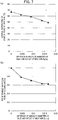
- FIG. 5(a) shows as a result of the cooling performance test a relationship between a difference in absolute humidities at an inlet (inlet end) and an outlet (outlet end) of the heat sink and an average temperature of an inner surface of the heat sink.
- the difference in the absolute humidities at the inlet and the outlet of the heat sink refers to a difference in the absolute humidities obtained by subtracting the absolute humidity at the outlet of the heat sink from the absolute humidity at the inlet of the heat sink. If the cooling air does not include the water mist, the absolute humidity difference between the inlet and the outlet of the heat sink becomes zero.
- FIG. 5(b) shows as a result of the cooling performance test a relationship between the difference in the absolute humidities at the inlet and the outlet of the heat sink and a predetermined mass flow ratio of the cooling air.
- the predetermined mass flow ratio refers to, based on a condition in which the cooling air does not include the water-generated mist, a ratio of the flow rate of the cooling air required to maintain the average temperature of the inner surface of the heat sink at a predetermined temperature.
- FIG. 5(b) it was found that, as the absolute humidity difference between the inlet and the outlet of the heat sink increases, the predetermined mass flow ratio decreases, and sufficient cooling performance is demonstrated even if the flow rate of the cooling air is reduced.
Landscapes
- Engineering & Computer Science (AREA)
- Microelectronics & Electronic Packaging (AREA)
- Physics & Mathematics (AREA)
- Thermal Sciences (AREA)
- Mechanical Engineering (AREA)
- Aviation & Aerospace Engineering (AREA)
- Cooling Or The Like Of Electrical Apparatus (AREA)
Abstract
Description
- The present disclosure relates , to a cooling device for cooling an electronic device such as a power electronics-based device.
- In recent times, a huge number of electronic devices are installed in a moving body such as an aircraft, a ship, a car, and the like. These electronic devices include power electronics-based devices that require high withstand voltage and high current. Moreover, because the electronic devices generate heat when operated, cooling devices are typically provided to cool these devices. The configuration of a conventional cooling device for electronic device (hereinafter referred to as "cooling device" for convenience of explanation) is explained below (see Patent Literature 1).
- A conventional cooling device typically includes a heat sink (radiator) that is connected in a heat-conductive manner to an electronic device. The heat sink is constituted by a material having an excellent thermal conductivity, such as aluminum alloy, and includes a plurality of heat radiating fins capable of heat radiation (to radiate heat) . The cooling device includes a blower, such as a fan, that causes cooling air to flow from an inlet toward an outlet of the heat sink.
- In the conventional cooling device, the blower causes, while the electronic device is being operated, the cooling air to flow from the inlet of the heat sink toward the outlet of the heat sink. The heat generated by driving of the electronic device is transmitted to the heat sink and then radiated to the cooling air from the heat radiating fins. With such a configuration, the electronic device can be cooled and rise in the temperature of the electronic device can be suppressed.
- Patent Literature 2 discloses a background art related to the present disclosure. The disclosed refrigerant circulating type cooling device is constituted by connecting a cooling plate, which cools a semiconductor element that is a high temperature heating element of the electronic device, a condenser installed outside an aircraft, and a refrigerant pump.
-
- Patent Literature 1: Japanese Patent Application Laid-Open Publication No.
2012-164939 - Patent Literature 2: Japanese Patent Application Laid-Open Publication No.
2005-14627 - The amount of heat generated by an electronic device tends to increase following an increase in the performance of the electronic device, and as a result, sufficiently increasing the radiation performance of a heat sink, in other words, the cooling performance of a cooling device is necessary. Therefore, usually, the heat transfer coefficient between the heat sink and the cooling air is increased by employing measures such as forming the heat radiating fins in a complex shape or increasing the number of the heat radiating fins. On the other hand, if such measures are employed on the heat sink, the pressure loss in the heat sink increases, resulting in upsizing of the blower and an increase in the energy consumption required for blowing the air.
- In other words, there is a problem that sufficiently increasing the cooling performance of the cooling device while suppressing the upsizing of the blower and the increase in the energy consumption required for blowing the air is not easy.
- In the view of above circumstances, an object of the present disclosure is to provide a cooling device for electronic device that can solve the above-mentioned problems.
- According to one aspect of the present disclosure, a cooling device for an electronic device, includes a heat sink that is in thermal contact with the electronic device; and a mist supplier that supplies mist to the heat sink and that is arranged upstream of the heat sink in a flow direction of cooling air passing via the heat sink.
- According to the present disclosure, a cooling device for electronic device that can sufficiently increase the cooling performance while suppressing the upsizing of the blower and the increase in the energy consumption required for blowing the air can be provided.
-
- [
Fig. 1] FIG. 1 is a schematic front view of a cooling device for electronic device according to an embodiment of the present disclosure. - [
Fig. 2] FIG. 2 is a schematic plan view of the cooling device for electronic device according to the embodiment of the present disclosure. - [
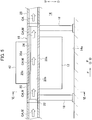
Fig. 3] FIG. 3 is a schematic front sectional view of a peripheral structure that includes a mist supplier according to the embodiment of the present disclosure. - [
Fig. 4] FIG. 4 is a cross-sectional view when seen from a direction indicated by a IV-IV line shown inFIG. 3 . - [
Fig. 5] FIG. 5 is a schematic front sectional view of a peripheral structure that includes a heat sink according to the embodiment of the present disclosure. - [
Fig. 6] FIG. 6 is a cross-sectional view when seen from a direction indicated by a VI-VI line shown inFIG. 5 . - [
Fig. 7] FIG. 7 (a) is a diagram showing a relation between a difference in absolute humidities at an inlet and an outlet of the heat sink and an average temperature of an inner surface of the heat sink, andFIG. 7 (b) is a diagram showing a relation between the difference in the absolute humidities at the inlet and the outlet of the heat sink and a predetermined mass flow ratio of cooling air. - Exemplary embodiments of the present disclosure are explained with reference to the accompanying drawings. The term "arrange / arranged" refers to a case in which a structural component is directly arranged and also refers to a case in which a structural component is indirectly arranged via another member. The term "include / included" refers to a case in which a structural member is directly included and also refers to a case in which a structural component is indirectly included via another member. The term "downstream" refers to downstream in a flow direction of cooling air, and "upstream" refers to upstream in the flow direction of the cooling air. In drawings, a reference letter "F" denotes the flow direction of the cooling air, a reference letter "P" denotes a direction orthogonal to the flow direction of the cooling air, a reference letter "U" denotes an upward direction (upward in the vertical direction), and a reference letter "D" denotes a downward direction (downward in the vertical direction).
- As shown in
FIGs. 1 and2 , a cooling device for electronic device (hereinafter referred to as "cooling device" for convenience of explanation) 10 according to an embodiment of the present disclosure is a device that coolsmotor drivers cooling device 10 is installed, for example, on afloor 14a of anengine room 14 of an aircraft. Themotor driver 12 that is to be cooled is an example of a power electronics-based device installed in the aircraft. Themotor driver 12 is a driver that drives a not-shown taxiing motor that causes not-shown wheels of the aircraft to rotate. - The
cooling device 10 includes aheat sink 16. Theheat sink 16 is installed, for example, on thefloor 14a of theengine room 14 by using a plurality ofstruts 18. - As shown in
FIGs. 5 and6 , theheat sink 16 is constituted by, for example, a material with an excellent thermal conductivity such as aluminum or aluminum alloy. Theheat sink 16 includes a base (heat sink base) 20 formed in a square pipe-like shape. Thebase 20 includes acooling passage 22 that is formed on the inner side of (inside) thebase 20. Air from a passenger cabin flows into thecooling passage 22 as cooling air CA. Thebase 20 is connected in a heat-conductive manner to themotor driver 12. In other words, at thebase 20, theheat sink 16 is in thermal contact with themotor driver 12. For example, themotor driver 12 is installed on a lowerouter surface 20a of thebase 20 of theheat sink 16. - The
base 20 has a plurality of firstheat radiating fins 24 arranged on a lowerinner surface 20b thereof. The firstheat radiating fins 24 are arranged at intervals in a direction P orthogonal to a flow direction F of the cooling air CA. The firstheat radiating fin 24 is formed in a plate shape and extends in the flow direction F of the cooling air CA. Moreover, theheat sink base 20 includes a plurality of secondheat radiating fins 26 installed on an upperinner surface 20c in thebase 20. The secondheat radiating fins 26 are arranged at intervals alternately with the first heat radiating fins 24 in the direction P. The secondheat radiating fin 26 is formed in a plate shape and extends in the flow direction F of the cooling air CA. - Alternately, the first heat radiating fins 24 and the second
heat radiating fins 26 can be formed in the form of a pin that extends in an upward direction U or a downward direction D. If formed so, the first heat radiating fins 24 and the secondheat radiating fins 26 are arranged at intervals in the direction F and the direction P, respectively. Alternatively, the secondheat radiating fins 26 can be omitted from the configuration of theheat sink 16. Alternatively, instead of thestruts 18, theheat sink 16 can be installed on the floor of theengine room 14 by using other supporting units such as a pedestal. - The
heat sink 16 includes on downstream thereof acollecting duct 28 that collects the cooling air CA. The collectingduct 28 communicates with thecooling passage 22 of theheat sink 16. Moreover, the collectingduct 28 includes on downstream thereof anair outlet 30 that sends the cooling air CA outside. - As shown in
FIGs. 1 and2 , thecooling device 10 includes a compressor (electric compressor) 32 arranged downstream of theheat sink 16 for sucking and compressing the cooling air CA. Thecompressor 32 is installed on thefloor 14a of theengine room 14 by using a plurality ofstruts 34. Thecompressor 32 is an example of a blower that causes the cooling air CA to flow from an inlet toward an outlet of thecooling passage 22 of theheat sink 16. Thecompressor 32 - The
compressor 32 includes acompressor housing 36, animpeller 38 that is rotatably arranged in thecompressor housing 36, and acompressor motor 40 arranged in thecompressor housing 36 and that rotates theimpeller 38. Thecompressor motor 40 is driven by themotor driver 42. Themotor driver 42 is connected in a heat-conductive manner to theheat sink 16. In other words, at thebase 20, theheat sink 16 is in thermal contact with themotor driver 42. For example, themotor driver 42 is installed on an upperouter surface 20d of thebase 20 of theheat sink 16. - The
compressor housing 36 includes anair inlet 44 that is arranged upstream of theimpeller 38 and that takes in the cooling air CA. Theair inlet 44 communicates with theair outlet 30 via acoupling 46. Thecompressor housing 36 includes a spiralscroll flow path 48 that is arranged downstream of theimpeller 38 in thecompressor housing 36 and that collects the compressed cooling air CA. Furthermore, thecompressor housing 36 includes arranged on the peripheral side thereof anair discharging port 50 for discharging the compressed cooling air CA. Theair discharging port 50 communicates with the outside of the aircraft via a not-shown discharge pipe. - Instead of installing the
electric compressor 32 by using thestruts 34, theelectric compressor 32, however, can be installed on thefloor 14a of theengine room 14 by using other supporting units such as a pedestal. - The
cooling device 10 includes, in the flow direction F of the cooling air CA that passes via theheat sink 16, amist supplier 52 arranged upstream of theheat sink 16. Themist supplier 52 supplies mist M to thecooling passage 22 of theheat sink 16 by using ultrasonic waves and the like. Themist supplier 52 is installed on thefloor 14a of theengine room 14 by using a plurality ofstruts 54. The main constituent (ingredient) of the mist M is, for example, water. - As shown in
FIGs. 3 and4 , themist supplier 52 includes a storage tank (for example, a water tank) 56 that stores the ingredient (for example, water W) of the mist M. Thestorage tank 56 is installed on thefloor 14a of theengine room 14 by using thestruts 54. Thestorage tank 56 is connected to atank 58 installed at an appropriate position in theengine room 14 for maintaining the level of the water W in thestorage tank 56 at a predetermined water level or higher. At the bottom of thestorage tank 56 is arranged a piezoelectric vibrator (an example of a vibrator) 60. Thepiezoelectric vibrator 60 is electrically connected to adriver circuit 62 installed at an appropriate position in theengine room 14. Upon receiving a high-frequency voltage from thedriver circuit 62, thepiezoelectric vibrator 60 vibrates, transmits (generates) the ultrasonic waves toward the surface of the water W stored in thestorage tank 56, and atomizes the water W. - The
storage tank 56 includes a first connectingmember 64 arranged upstream (on a side away from the heat sink 16) at the top of thestorage tank 56. The first connectingmember 64 is formed in, for example, a square pipe-like shape and includes internally (inside) anintroduction passage 66. Theintroduction passage 66 introduces the cooling air CA to a space inside thestorage tank 56. Moreover, thestorage tank 56 includes a second connectingmember 68 arranged downstream (on a side near the heat sink 16) at the top of thestorage tank 56. The second connectingmember 68 is formed in, for example, a square pipe-like shape, and includes internally a lead-out passage 70. The lead-out passage 70 sends out from the space inside thestorage tank 56 the cooling air CA which includes the mist M. - The
mist supplier 52 includes anintroduction duct 72 arranged between an upper part of the first connectingmember 64 and an upper part of the second connectingmember 68. Theintroduction duct 72 introduces to thecooling passage 22 of theheat sink 16 the cooling air CA that includes the water mist M. Theintroduction duct 72 internally communicates with theintroduction passage 66 of the first connectingmember 64 on an inlet side thereof. Theintroduction duct 72 internally communicates with the lead-out passage 70 of the second connectingmember 68 on an outlet side thereof. Moreover, theintroduction duct 72 includes arranged in the middle thereof (that is, between a portion connected to theintroduction passage 66 and a portion connected to the lead-out passage 70) an adjusting plate (baffle plate) 74. The adjustingplate 74 has a plurality of through-holes 76 via which the cooling air CA passes, and is constituted by, for example, a perforated metal. - The adjusting
plate 74 arranged in theintroduction duct 72 adjusts a flow rate of the cooling air CA to be introduced to theintroduction passage 66 of the first connectingmember 64. In other words, the adjustingplate 74 leads to the introduction passage 66 a part of the cooling air CA flown in from an inlet of theintroduction duct 72, and leads out the remaining cooling air CA directly toward an outlet of theintroduction duct 72 without passing via thestorage tank 56. That is, themist supplier 52 includes a generating source for the mist M (hereinafter referred to as a mist generating source) 53 (seeFIG. 3 ) and two flow paths that share an inlet of the cooling air CA and an outlet of the cooling air CA that flows towards the heat sink 16 (the cooling passage 22). Themist generating source 53 includes thestorage tank 56 and thepiezoelectric vibrator 60. One of the two flow paths (a first flow path: theintroduction passage 66, thestorage tank 56, and the lead-out passage 70) passes via themist generating source 53, and the other flow path (a second flow path: the introduction duct 72) does not pass via themist generating source 53. Furthermore, in the second flow path, the adjustingplate 74 explained above is arranged between a branching point and a confluence point thereof from and to the first flow path, and the adjustingplate 74 adjusts the flow rate of the cooling air CA that flows via each flow path. - To adjust the flow rate of the cooling air CA to be introduced to the
introduction passage 66, theintroduction duct 72 can internally include on the inlet side thereof a not-shown throttle. Moreover, instead of installing themist supplier 52 by using thestruts 54, the mist supplier 52 (the storage tank 56) can be installed on thefloor 14a of theengine room 14 by using other supporting units such as a pedestal. - The
introduction duct 72 includes upstream thereof afilter 78 that cleans the cooling air CA. A mixingduct 80 arranged between theintroduction duct 72 and theheat sink 16 facilitates mixing of the cooling air CA and the mist M. An inlet arranged inside the mixingduct 80 communicates with the outlet arranged inside theintroduction duct 72. An outlet arranged inside the mixingduct 80 communicates with the inlet of thecooling passage 22 of the heat sink 16 (inside of the heat sink 16). - Alternatively, other intermediate members such as a connecting pipe can be interposed between the
introduction duct 72 and thefilter 78. - Next, effects and advantages of the embodiments according to the present disclosure are explained.
- During the operation of the
motor driver 12, when theimpeller 38 rotates by the driving of thecompressor motor 40, thecompressor 32 sucks and compresses the cooling air CA. Then, suction action of thecompressor 32 causes the cooling air CA to flow from the inlet toward the outlet of thecooling passage 22 of theheat sink 16 via thefilter 78, theintroduction duct 72, and the like. The heat generated by the operation of themotor driver 12 of the taxiing motor is transmitted to theheat sink 16 and then radiated to the cooling air CA via the firstheat radiating fins 24, theheat sink base 20, and the like. At the same time, the heat generated by the operation of themotor driver 42 of thecompressor motor 40 is transmitted to theheat sink 16 and then radiated to the cooling air CA via the secondheat radiating fins 26, theheat sink base 20, and the like. After receiving the heat generated by themotor drivers compressor 32 sucks and compresses the cooling air CA, and then discharges the same to the outside of the aircraft via theair discharging port 50. - When the cooling air CA is flowing from the inlet to the outlet of the
cooling passage 22 of theheat sink 16 via thefilter 78, theintroduction duct 72, and the like, thedriver circuit 62 supplies a high-frequency voltage to thepiezoelectric vibrator 60. Upon receiving the voltage, thepiezoelectric vibrator 60 vibrates and transmits the ultrasonic waves toward the surface of the water W in thestorage tank 56. When the ultrasonic waves are transmitted in the water W, the mist M is generated from the surface of the water W in thestorage tank 56. Inside thestorage tank 56, the generated mist M mixes with the cooling air CA introduced from theintroduction passage 66 of the first connectingmember 64. The cooling air CA in which the mist M is included is then sent to the outlet of theintroduction duct 72 via the lead-out passage 70 of the second connectingmember 68 and supplied to the inlet of thecooling passage 22 of theheat sink 16 via the mixingduct 80. Accordingly, when compared with, for example, a configuration that uses dry air to perform cooling, rise in the temperature of the cooling air CA in thecooling passage 22 of theheat sink 16 can be further suppressed by the cooling effect of the latent heat of vaporization (heat of vaporization) of the mist M. Consequently, the temperature difference between theheat sink 16 and the cooling air CA can be increased without increasing the heat transfer coefficient between theheat sink 16 and the cooling air CA. In other words, the temperature difference between theheat sink 16 and the cooling air CA can be increased without employing measures such as forming the firstheat radiating fin 24 and the like in a complex shape or increasing the number of the firstheat radiating fins 24 and the like. - The adjusting
plate 74 arranged in theintroduction duct 72 adjusts the flow rate of the cooling air CA to be introduced to theintroduction passage 66. When the cooling air CA is supplied excessively to thestorage tank 56, disturbance in thestorage tank 56 accelerates leading to an increase in the particle size of the mist M. Increase in the particle size of the mist M causes increase in a resistance of the flow of the cooling air CA in the cooling passage 22 (for example, space between the firstheat radiating fins 24 and the second heat radiating fins 26). Increase in the resistance, for example, may affect the change in the cooling capability corresponding to the flow rate (flow speed) of the cooling air CA, and controlling the flow rate of the cooling air CA may become difficult. The adjustingplate 74 controls the excessive supply of the cooling air CA to thestorage tank 56, and suppresses undesired increase in the particle size of the mist M, in other words, increase of the large-particle sized components in a particle size distribution of the mist M. - With the configuration explained above, the
motor driver 12 of the taxiing motor can be sufficiently cooled, and rise in the temperature of themotor driver 12 of the taxiing motor can be suppressed. Also, themotor driver 42 of thecompressor motor 40 can be sufficiently cooled, and rise in the temperature of themotor driver 42 of thecompressor motor 40 can be suppressed. - Therefore, according to the embodiments of the present disclosure explained above, the temperature difference between the
heat sink 16 and the cooling air CA can be increased without employing measures such as forming the firstheat radiating fin 24 and the like in a complex shape or increasing the number of the firstheat radiating fins 24 and the like. Therefore, according to the embodiments of the present disclosure, the radiation performance of theheat sink 16, in other words, the cooling performance of thecooling device 10 can be sufficiently improved while reducing the pressure loss in thecooling passage 22 of theheat sink 16 and controlling the increase in the size of thecompressor 32 and the energy consumption required for blowing air. - In particular, according to the embodiments of the present disclosure, even if the flow rate of the cooling air CA is reduced, the cooling performance of the
cooling device 10 can be sufficiently improved and the cooling air CA can be effectively utilized in the aircraft. - The present disclosure, however, is not limited to the embodiments explained above, and can be implemented, for example, in the following various modes. The
cooling device 10 can be used for cooling a power electronics-based device other than themotor driver 12, or an electronic device other than the power electronics-based device. Instead of using thecompressor 32, a not-shown other blower such as a fan can be used to cause the cooling air CA to flow from the inlet of thecooling passage 22 of theheat sink 16 toward the outlet of the same. - The scope of rights included in the present disclosure is not limited to the embodiments explained above.
- A test device that is simulated as a cooling device was manufactured, and a cooling performance test was conducted on the test device. During the cooling performance test, the amount of water-generated mist included in the cooling air was changed. From a heat sink included in the test device, a plurality of first heat radiating fins and a plurality of second heat radiating fins were omitted, and instead of including an electronic device, the heat sink included in the test device included a heater (heating element) on the lower surface thereof.
-
FIG. 5(a) shows as a result of the cooling performance test a relationship between a difference in absolute humidities at an inlet (inlet end) and an outlet (outlet end) of the heat sink and an average temperature of an inner surface of the heat sink. As shown inFIG. 5(a) , it was found that, as the difference in the absolute humidities at the inlet and the outlet of the heat sink increases, the average temperature of the inner surface of the heat sink decreases, leading to an improvement in the cooling performance. The difference in the absolute humidities at the inlet and the outlet of the heat sink refers to a difference in the absolute humidities obtained by subtracting the absolute humidity at the outlet of the heat sink from the absolute humidity at the inlet of the heat sink. If the cooling air does not include the water mist, the absolute humidity difference between the inlet and the outlet of the heat sink becomes zero. -
FIG. 5(b) shows as a result of the cooling performance test a relationship between the difference in the absolute humidities at the inlet and the outlet of the heat sink and a predetermined mass flow ratio of the cooling air. In this scenario, the predetermined mass flow ratio refers to, based on a condition in which the cooling air does not include the water-generated mist, a ratio of the flow rate of the cooling air required to maintain the average temperature of the inner surface of the heat sink at a predetermined temperature. As shown inFIG. 5(b) , it was found that, as the absolute humidity difference between the inlet and the outlet of the heat sink increases, the predetermined mass flow ratio decreases, and sufficient cooling performance is demonstrated even if the flow rate of the cooling air is reduced.
Claims (5)
- A cooling device for an electronic device, comprising:a heat sink that is in thermal contact with the electronic device; anda mist supplier that supplies mist to the heat sink, arranged upstream of the heat sink in a flow direction of cooling air passing via the heat sink.
- The cooling device according to claim 1 further comprising a blower that causes the cooling air to flow from an inlet toward an outlet of the heat sink.
- The cooling device according to claim 2, wherein the blower is a compressor that is arranged downstream of the heat sink and that sucks and compresses the cooling air.
- The cooling device according to claim 3, wherein a driver of a compressor motor of the compressor is in thermal contact with the heat sink.
- The cooling device according to claim 1, wherein the mist supplier includes
a mist generating source that generates the mist included in the cooling air, and
a first flow path and a second flow path that share an inlet of the cooling air and an outlet of the cooling air that flows toward the heat sink, wherein
the first flow path passes via the mist generating source, and
the second flow path does not pass via the mist generating source, wherein
an adjusting plate for cooling air is arranged in the second flow path between a branching point and a confluence point with the first flow path.
Applications Claiming Priority (2)
| Application Number | Priority Date | Filing Date | Title |
|---|---|---|---|
| JP2015203566 | 2015-10-15 | ||
| PCT/JP2016/068749 WO2017064886A1 (en) | 2015-10-15 | 2016-06-24 | Cooling device for electronic apparatus |
Publications (3)
| Publication Number | Publication Date |
|---|---|
| EP3352549A1 true EP3352549A1 (en) | 2018-07-25 |
| EP3352549A4 EP3352549A4 (en) | 2019-08-07 |
| EP3352549B1 EP3352549B1 (en) | 2020-12-09 |
Family
ID=58517977
Family Applications (1)
| Application Number | Title | Priority Date | Filing Date |
|---|---|---|---|
| EP16855140.6A Active EP3352549B1 (en) | 2015-10-15 | 2016-06-24 | Cooling device for electronic device |
Country Status (4)
| Country | Link |
|---|---|
| US (1) | US10292315B2 (en) |
| EP (1) | EP3352549B1 (en) |
| JP (1) | JP6526822B2 (en) |
| WO (1) | WO2017064886A1 (en) |
Families Citing this family (2)
| Publication number | Priority date | Publication date | Assignee | Title |
|---|---|---|---|---|
| US11685543B1 (en) * | 2022-03-24 | 2023-06-27 | Toyota Motor Engineering & Manufacturing North America, Inc. | Vibrating actuator based hybrid cooling systems for electric machines |
| US12576693B2 (en) * | 2024-01-12 | 2026-03-17 | Toyota Motor Engineering & Manufacturing North America, Inc. | Cooling systems and assemblies, and vehicles including the same |
Family Cites Families (16)
| Publication number | Priority date | Publication date | Assignee | Title |
|---|---|---|---|---|
| JPS5892796U (en) * | 1981-12-18 | 1983-06-23 | 日本電信電話株式会社 | Electronic equipment cooling system |
| JPH0725357B2 (en) | 1985-02-07 | 1995-03-22 | 三菱電機株式会社 | Streamlined containment vessel cooling system |
| JPS6461999A (en) | 1987-09-02 | 1989-03-08 | Mitsubishi Heavy Ind Ltd | Cooling device for apparatus of moving body |
| US6349760B1 (en) * | 1999-10-22 | 2002-02-26 | Intel Corporation | Method and apparatus for improving the thermal performance of heat sinks |
| JPWO2002046677A1 (en) | 2000-12-04 | 2004-04-08 | 富士通株式会社 | Cooling system and heat sink |
| US6970356B2 (en) * | 2002-07-16 | 2005-11-29 | Tseng Jyi Peng | Heat sink system |
| US6955063B2 (en) * | 2003-06-14 | 2005-10-18 | Nanomist Systems, Llc | Cooling of electronics and high density power dissipation systems by fine-mist flooding |
| JP2005014627A (en) | 2003-06-23 | 2005-01-20 | Matsushita Electric Ind Co Ltd | Aircraft electronic equipment cooling system |
| JP4177796B2 (en) | 2004-07-30 | 2008-11-05 | エスペック株式会社 | Cooling system |
| US8037926B2 (en) * | 2007-06-21 | 2011-10-18 | International Business Machines Corporation | Method and apparatus for chip cooling |
| US8760017B2 (en) * | 2010-07-05 | 2014-06-24 | Hanning Elektro-Werke Gmbh & Co. Kg | Electric machine |
| JP2012164939A (en) | 2011-02-09 | 2012-08-30 | Toshiba Corp | Electronic apparatus |
| JP2013074214A (en) * | 2011-09-28 | 2013-04-22 | Fuji Electric Co Ltd | Power semiconductor cooling system |
| JP5304865B2 (en) * | 2011-09-29 | 2013-10-02 | ダイキン工業株式会社 | Air conditioner outdoor unit |
| JP2013164048A (en) | 2012-02-13 | 2013-08-22 | Panasonic Corp | Electric compressor |
| JP6065817B2 (en) * | 2013-11-19 | 2017-01-25 | 株式会社デンソー | Vehicle interior temperature detection module and vehicle air conditioner equipped with the same |
-
2016
- 2016-06-24 EP EP16855140.6A patent/EP3352549B1/en active Active
- 2016-06-24 WO PCT/JP2016/068749 patent/WO2017064886A1/en not_active Ceased
- 2016-06-24 JP JP2017545100A patent/JP6526822B2/en active Active
-
2017
- 2017-11-15 US US15/813,293 patent/US10292315B2/en active Active
Also Published As
| Publication number | Publication date |
|---|---|
| EP3352549A4 (en) | 2019-08-07 |
| EP3352549B1 (en) | 2020-12-09 |
| JP6526822B2 (en) | 2019-06-05 |
| US10292315B2 (en) | 2019-05-14 |
| US20180077826A1 (en) | 2018-03-15 |
| WO2017064886A1 (en) | 2017-04-20 |
| JPWO2017064886A1 (en) | 2018-03-29 |
Similar Documents
| Publication | Publication Date | Title |
|---|---|---|
| JP4348358B2 (en) | Aircraft air conditioning system and cooling ram air circuit | |
| US7257956B2 (en) | Cooling apparatus | |
| JP6419837B2 (en) | Moving body cooling apparatus having liquid heat exhaust system | |
| US11262133B2 (en) | Aircraft electronics thermal regulation systems | |
| CN101952172B (en) | Systems and methods for ventilating blast zones of spacecraft | |
| JP6093267B2 (en) | Circulating cooling and heating device | |
| CN104781749A (en) | Module-type data center and control method thereof | |
| EP3276279A1 (en) | Heat pump hot-water-supply outdoor device, and hot-water-supply device | |
| US20120096882A1 (en) | Temperature regulation system with active jetting type refrigerant supply and regulation | |
| US10292315B2 (en) | Cooling device for electronic device | |
| KR101345980B1 (en) | Ventilation modules intergrated controller | |
| KR101599461B1 (en) | Air conditioner for preventing condensation of duct | |
| CN108882617A (en) | Driving device | |
| WO2017107719A1 (en) | Multi-axis manned aircraft | |
| US20090211736A1 (en) | Coolant circulating apparatus, and cooling apparatus including the same coolant circulating apparatus for electric and/or electronic device which generates heat | |
| CN104620485B (en) | The convertor device of air conditioner | |
| US20130277012A1 (en) | Apparatus to cool a computing device | |
| CN110291334A (en) | Air conditioner | |
| JP5439562B2 (en) | Air conditioning system | |
| WO2016035462A1 (en) | System for cooling electrically driven unit of aircraft | |
| CN106364663B (en) | Aircraft air conditioning module cabin | |
| JP2013164048A (en) | Electric compressor | |
| CN112493876A (en) | Micro steaming and baking device | |
| JP2015159085A (en) | Temperature adjustment device | |
| EP2991107A2 (en) | Heat exchanger device in directed flow system |
Legal Events
| Date | Code | Title | Description |
|---|---|---|---|
| STAA | Information on the status of an ep patent application or granted ep patent |
Free format text: STATUS: THE INTERNATIONAL PUBLICATION HAS BEEN MADE |
|
| PUAI | Public reference made under article 153(3) epc to a published international application that has entered the european phase |
Free format text: ORIGINAL CODE: 0009012 |
|
| STAA | Information on the status of an ep patent application or granted ep patent |
Free format text: STATUS: REQUEST FOR EXAMINATION WAS MADE |
|
| 17P | Request for examination filed |
Effective date: 20171110 |
|
| AK | Designated contracting states |
Kind code of ref document: A1 Designated state(s): AL AT BE BG CH CY CZ DE DK EE ES FI FR GB GR HR HU IE IS IT LI LT LU LV MC MK MT NL NO PL PT RO RS SE SI SK SM TR |
|
| AX | Request for extension of the european patent |
Extension state: BA ME |
|
| DAV | Request for validation of the european patent (deleted) | ||
| DAX | Request for extension of the european patent (deleted) | ||
| A4 | Supplementary search report drawn up and despatched |
Effective date: 20190708 |
|
| RIC1 | Information provided on ipc code assigned before grant |
Ipc: H05K 7/20 20060101AFI20190702BHEP Ipc: B64C 25/36 20060101ALI20190702BHEP |
|
| GRAP | Despatch of communication of intention to grant a patent |
Free format text: ORIGINAL CODE: EPIDOSNIGR1 |
|
| STAA | Information on the status of an ep patent application or granted ep patent |
Free format text: STATUS: GRANT OF PATENT IS INTENDED |
|
| INTG | Intention to grant announced |
Effective date: 20200717 |
|
| GRAS | Grant fee paid |
Free format text: ORIGINAL CODE: EPIDOSNIGR3 |
|
| GRAA | (expected) grant |
Free format text: ORIGINAL CODE: 0009210 |
|
| STAA | Information on the status of an ep patent application or granted ep patent |
Free format text: STATUS: THE PATENT HAS BEEN GRANTED |
|
| RAP1 | Party data changed (applicant data changed or rights of an application transferred) |
Owner name: IHI CORPORATION Owner name: NATIONAL UNIVERSITY CORPORATION TOKYO UNIVERSITY OF AGRICULTURE AND TECHNOLOGY |
|
| AK | Designated contracting states |
Kind code of ref document: B1 Designated state(s): AL AT BE BG CH CY CZ DE DK EE ES FI FR GB GR HR HU IE IS IT LI LT LU LV MC MK MT NL NO PL PT RO RS SE SI SK SM TR |
|
| REG | Reference to a national code |
Ref country code: GB Ref legal event code: FG4D |
|
| REG | Reference to a national code |
Ref country code: AT Ref legal event code: REF Ref document number: 1344702 Country of ref document: AT Kind code of ref document: T Effective date: 20201215 Ref country code: CH Ref legal event code: EP |
|
| REG | Reference to a national code |
Ref country code: DE Ref legal event code: R096 Ref document number: 602016049624 Country of ref document: DE |
|
| REG | Reference to a national code |
Ref country code: IE Ref legal event code: FG4D |
|
| PG25 | Lapsed in a contracting state [announced via postgrant information from national office to epo] |
Ref country code: NO Free format text: LAPSE BECAUSE OF FAILURE TO SUBMIT A TRANSLATION OF THE DESCRIPTION OR TO PAY THE FEE WITHIN THE PRESCRIBED TIME-LIMIT Effective date: 20210309 Ref country code: RS Free format text: LAPSE BECAUSE OF FAILURE TO SUBMIT A TRANSLATION OF THE DESCRIPTION OR TO PAY THE FEE WITHIN THE PRESCRIBED TIME-LIMIT Effective date: 20201209 Ref country code: FI Free format text: LAPSE BECAUSE OF FAILURE TO SUBMIT A TRANSLATION OF THE DESCRIPTION OR TO PAY THE FEE WITHIN THE PRESCRIBED TIME-LIMIT Effective date: 20201209 Ref country code: GR Free format text: LAPSE BECAUSE OF FAILURE TO SUBMIT A TRANSLATION OF THE DESCRIPTION OR TO PAY THE FEE WITHIN THE PRESCRIBED TIME-LIMIT Effective date: 20210310 |
|
| REG | Reference to a national code |
Ref country code: AT Ref legal event code: MK05 Ref document number: 1344702 Country of ref document: AT Kind code of ref document: T Effective date: 20201209 |
|
| PG25 | Lapsed in a contracting state [announced via postgrant information from national office to epo] |
Ref country code: SE Free format text: LAPSE BECAUSE OF FAILURE TO SUBMIT A TRANSLATION OF THE DESCRIPTION OR TO PAY THE FEE WITHIN THE PRESCRIBED TIME-LIMIT Effective date: 20201209 Ref country code: BG Free format text: LAPSE BECAUSE OF FAILURE TO SUBMIT A TRANSLATION OF THE DESCRIPTION OR TO PAY THE FEE WITHIN THE PRESCRIBED TIME-LIMIT Effective date: 20210309 Ref country code: LV Free format text: LAPSE BECAUSE OF FAILURE TO SUBMIT A TRANSLATION OF THE DESCRIPTION OR TO PAY THE FEE WITHIN THE PRESCRIBED TIME-LIMIT Effective date: 20201209 |
|
| REG | Reference to a national code |
Ref country code: NL Ref legal event code: MP Effective date: 20201209 |
|
| PG25 | Lapsed in a contracting state [announced via postgrant information from national office to epo] |
Ref country code: NL Free format text: LAPSE BECAUSE OF FAILURE TO SUBMIT A TRANSLATION OF THE DESCRIPTION OR TO PAY THE FEE WITHIN THE PRESCRIBED TIME-LIMIT Effective date: 20201209 Ref country code: HR Free format text: LAPSE BECAUSE OF FAILURE TO SUBMIT A TRANSLATION OF THE DESCRIPTION OR TO PAY THE FEE WITHIN THE PRESCRIBED TIME-LIMIT Effective date: 20201209 |
|
| REG | Reference to a national code |
Ref country code: LT Ref legal event code: MG9D |
|
| PG25 | Lapsed in a contracting state [announced via postgrant information from national office to epo] |
Ref country code: PT Free format text: LAPSE BECAUSE OF FAILURE TO SUBMIT A TRANSLATION OF THE DESCRIPTION OR TO PAY THE FEE WITHIN THE PRESCRIBED TIME-LIMIT Effective date: 20210409 Ref country code: RO Free format text: LAPSE BECAUSE OF FAILURE TO SUBMIT A TRANSLATION OF THE DESCRIPTION OR TO PAY THE FEE WITHIN THE PRESCRIBED TIME-LIMIT Effective date: 20201209 Ref country code: SK Free format text: LAPSE BECAUSE OF FAILURE TO SUBMIT A TRANSLATION OF THE DESCRIPTION OR TO PAY THE FEE WITHIN THE PRESCRIBED TIME-LIMIT Effective date: 20201209 Ref country code: SM Free format text: LAPSE BECAUSE OF FAILURE TO SUBMIT A TRANSLATION OF THE DESCRIPTION OR TO PAY THE FEE WITHIN THE PRESCRIBED TIME-LIMIT Effective date: 20201209 Ref country code: LT Free format text: LAPSE BECAUSE OF FAILURE TO SUBMIT A TRANSLATION OF THE DESCRIPTION OR TO PAY THE FEE WITHIN THE PRESCRIBED TIME-LIMIT Effective date: 20201209 Ref country code: EE Free format text: LAPSE BECAUSE OF FAILURE TO SUBMIT A TRANSLATION OF THE DESCRIPTION OR TO PAY THE FEE WITHIN THE PRESCRIBED TIME-LIMIT Effective date: 20201209 Ref country code: CZ Free format text: LAPSE BECAUSE OF FAILURE TO SUBMIT A TRANSLATION OF THE DESCRIPTION OR TO PAY THE FEE WITHIN THE PRESCRIBED TIME-LIMIT Effective date: 20201209 |
|
| PG25 | Lapsed in a contracting state [announced via postgrant information from national office to epo] |
Ref country code: AT Free format text: LAPSE BECAUSE OF FAILURE TO SUBMIT A TRANSLATION OF THE DESCRIPTION OR TO PAY THE FEE WITHIN THE PRESCRIBED TIME-LIMIT Effective date: 20201209 Ref country code: PL Free format text: LAPSE BECAUSE OF FAILURE TO SUBMIT A TRANSLATION OF THE DESCRIPTION OR TO PAY THE FEE WITHIN THE PRESCRIBED TIME-LIMIT Effective date: 20201209 |
|
| REG | Reference to a national code |
Ref country code: DE Ref legal event code: R097 Ref document number: 602016049624 Country of ref document: DE |
|
| PG25 | Lapsed in a contracting state [announced via postgrant information from national office to epo] |
Ref country code: IS Free format text: LAPSE BECAUSE OF FAILURE TO SUBMIT A TRANSLATION OF THE DESCRIPTION OR TO PAY THE FEE WITHIN THE PRESCRIBED TIME-LIMIT Effective date: 20210409 |
|
| PLBE | No opposition filed within time limit |
Free format text: ORIGINAL CODE: 0009261 |
|
| STAA | Information on the status of an ep patent application or granted ep patent |
Free format text: STATUS: NO OPPOSITION FILED WITHIN TIME LIMIT |
|
| PG25 | Lapsed in a contracting state [announced via postgrant information from national office to epo] |
Ref country code: IT Free format text: LAPSE BECAUSE OF FAILURE TO SUBMIT A TRANSLATION OF THE DESCRIPTION OR TO PAY THE FEE WITHIN THE PRESCRIBED TIME-LIMIT Effective date: 20201209 Ref country code: AL Free format text: LAPSE BECAUSE OF FAILURE TO SUBMIT A TRANSLATION OF THE DESCRIPTION OR TO PAY THE FEE WITHIN THE PRESCRIBED TIME-LIMIT Effective date: 20201209 |
|
| 26N | No opposition filed |
Effective date: 20210910 |
|
| PG25 | Lapsed in a contracting state [announced via postgrant information from national office to epo] |
Ref country code: DK Free format text: LAPSE BECAUSE OF FAILURE TO SUBMIT A TRANSLATION OF THE DESCRIPTION OR TO PAY THE FEE WITHIN THE PRESCRIBED TIME-LIMIT Effective date: 20201209 Ref country code: SI Free format text: LAPSE BECAUSE OF FAILURE TO SUBMIT A TRANSLATION OF THE DESCRIPTION OR TO PAY THE FEE WITHIN THE PRESCRIBED TIME-LIMIT Effective date: 20201209 |
|
| PG25 | Lapsed in a contracting state [announced via postgrant information from national office to epo] |
Ref country code: ES Free format text: LAPSE BECAUSE OF FAILURE TO SUBMIT A TRANSLATION OF THE DESCRIPTION OR TO PAY THE FEE WITHIN THE PRESCRIBED TIME-LIMIT Effective date: 20201209 Ref country code: MC Free format text: LAPSE BECAUSE OF FAILURE TO SUBMIT A TRANSLATION OF THE DESCRIPTION OR TO PAY THE FEE WITHIN THE PRESCRIBED TIME-LIMIT Effective date: 20201209 |
|
| REG | Reference to a national code |
Ref country code: CH Ref legal event code: PL |
|
| REG | Reference to a national code |
Ref country code: BE Ref legal event code: MM Effective date: 20210630 |
|
| PG25 | Lapsed in a contracting state [announced via postgrant information from national office to epo] |
Ref country code: LU Free format text: LAPSE BECAUSE OF NON-PAYMENT OF DUE FEES Effective date: 20210624 |
|
| PG25 | Lapsed in a contracting state [announced via postgrant information from national office to epo] |
Ref country code: LI Free format text: LAPSE BECAUSE OF NON-PAYMENT OF DUE FEES Effective date: 20210630 Ref country code: IE Free format text: LAPSE BECAUSE OF NON-PAYMENT OF DUE FEES Effective date: 20210624 Ref country code: CH Free format text: LAPSE BECAUSE OF NON-PAYMENT OF DUE FEES Effective date: 20210630 |
|
| PG25 | Lapsed in a contracting state [announced via postgrant information from national office to epo] |
Ref country code: IS Free format text: LAPSE BECAUSE OF FAILURE TO SUBMIT A TRANSLATION OF THE DESCRIPTION OR TO PAY THE FEE WITHIN THE PRESCRIBED TIME-LIMIT Effective date: 20210409 |
|
| PG25 | Lapsed in a contracting state [announced via postgrant information from national office to epo] |
Ref country code: BE Free format text: LAPSE BECAUSE OF NON-PAYMENT OF DUE FEES Effective date: 20210630 |
|
| PG25 | Lapsed in a contracting state [announced via postgrant information from national office to epo] |
Ref country code: CY Free format text: LAPSE BECAUSE OF FAILURE TO SUBMIT A TRANSLATION OF THE DESCRIPTION OR TO PAY THE FEE WITHIN THE PRESCRIBED TIME-LIMIT Effective date: 20201209 |
|
| PG25 | Lapsed in a contracting state [announced via postgrant information from national office to epo] |
Ref country code: HU Free format text: LAPSE BECAUSE OF FAILURE TO SUBMIT A TRANSLATION OF THE DESCRIPTION OR TO PAY THE FEE WITHIN THE PRESCRIBED TIME-LIMIT; INVALID AB INITIO Effective date: 20160624 |
|
| PG25 | Lapsed in a contracting state [announced via postgrant information from national office to epo] |
Ref country code: MK Free format text: LAPSE BECAUSE OF FAILURE TO SUBMIT A TRANSLATION OF THE DESCRIPTION OR TO PAY THE FEE WITHIN THE PRESCRIBED TIME-LIMIT Effective date: 20201209 |
|
| PG25 | Lapsed in a contracting state [announced via postgrant information from national office to epo] |
Ref country code: MT Free format text: LAPSE BECAUSE OF FAILURE TO SUBMIT A TRANSLATION OF THE DESCRIPTION OR TO PAY THE FEE WITHIN THE PRESCRIBED TIME-LIMIT Effective date: 20201209 |
|
| PGFP | Annual fee paid to national office [announced via postgrant information from national office to epo] |
Ref country code: DE Payment date: 20250429 Year of fee payment: 10 |
|
| PGFP | Annual fee paid to national office [announced via postgrant information from national office to epo] |
Ref country code: GB Payment date: 20250501 Year of fee payment: 10 |
|
| PGFP | Annual fee paid to national office [announced via postgrant information from national office to epo] |
Ref country code: FR Payment date: 20250508 Year of fee payment: 10 |
|
| PG25 | Lapsed in a contracting state [announced via postgrant information from national office to epo] |
Ref country code: TR Free format text: LAPSE BECAUSE OF FAILURE TO SUBMIT A TRANSLATION OF THE DESCRIPTION OR TO PAY THE FEE WITHIN THE PRESCRIBED TIME-LIMIT Effective date: 20201209 |