EP3352479A1 - Hörgerät mit flexiblem einführungselement - Google Patents
Hörgerät mit flexiblem einführungselement Download PDFInfo
- Publication number
- EP3352479A1 EP3352479A1 EP17189363.9A EP17189363A EP3352479A1 EP 3352479 A1 EP3352479 A1 EP 3352479A1 EP 17189363 A EP17189363 A EP 17189363A EP 3352479 A1 EP3352479 A1 EP 3352479A1
- Authority
- EP
- European Patent Office
- Prior art keywords
- insertion member
- hearing aid
- wire
- tube
- earpiece
- Prior art date
- Legal status (The legal status is an assumption and is not a legal conclusion. Google has not performed a legal analysis and makes no representation as to the accuracy of the status listed.)
- Withdrawn
Links
Images


Classifications
-
- H—ELECTRICITY
- H04—ELECTRIC COMMUNICATION TECHNIQUE
- H04R—LOUDSPEAKERS, MICROPHONES, GRAMOPHONE PICK-UPS OR LIKE ACOUSTIC ELECTROMECHANICAL TRANSDUCERS; DEAF-AID SETS; PUBLIC ADDRESS SYSTEMS
- H04R25/00—Deaf-aid sets, i.e. electro-acoustic or electro-mechanical hearing aids; Electric tinnitus maskers providing an auditory perception
-
- H—ELECTRICITY
- H04—ELECTRIC COMMUNICATION TECHNIQUE
- H04R—LOUDSPEAKERS, MICROPHONES, GRAMOPHONE PICK-UPS OR LIKE ACOUSTIC ELECTROMECHANICAL TRANSDUCERS; DEAF-AID SETS; PUBLIC ADDRESS SYSTEMS
- H04R2460/00—Details of hearing devices, i.e. of ear- or headphones covered by H04R1/10 or H04R5/033 but not provided for in any of their subgroups, or of hearing aids covered by H04R25/00 but not provided for in any of its subgroups
- H04R2460/17—Hearing device specific tools used for storing or handling hearing devices or parts thereof, e.g. placement in the ear, replacement of cerumen barriers, repair, cleaning hearing devices
Definitions
- the present disclosure relates to a hearing aid comprising a housing configured to be arranged behind the pinna of a user and configured with an insertion member allowing easy insertion of the earpiece in the ear canal of a user.
- the disclosure more particularly relates to a hearing aid comprising an earpiece, and a tube or wire, where the tube or wire in one end is connected to the housing and in a second end is connected to the earpiece.
- the disclosure relates to a kit of parts comprising a tool and an insertion member, wherein the tool is used to attach the insertion member to the tube of wire of a hearing aid.
- the earpiece To get the earpiece into the right position in the ear canal, many users press on the tube/wire that just flexes instead of pressing the earpiece deeper into the ear canal. Often, the earpiece comprises a speaker which if not inserted correctly into the ear canal, will cause an unintended error in the needed amplification for a given hearing loss. It may cause a lower feedback margin and the retention of the earpiece in the ear canal may be insufficient causing the earpiece to fall out of the ear canal.
- the hearing aid comprises a housing configured to be arranged behind the pinna of a user, an earpiece, and a tube or wire.
- the tube or wire is in one end connected to the housing and in a second end connected to the earpiece.
- the hearing aid further comprises an insertion member, the insertion member being configured to connect with said tube or wire and to contact the earpiece of the hearing aid, wherein the insertion member is configured to ease insertion of the hearing aid into the ear canal of a hearing aid user, and where the insertion member comprises a contact portion, allowing a user to push on the insertion member forcing the earpiece of the hearing aid into the ear canal of the user.
- the insertion member furthermore comprises a front end and a rear end and at least one flexible portion arranged between the front end and the rear end.
- a hearing aid having an insertion member an easy insertion of the earpiece into the ear canal of a hearing aid user may be achieved.
- the insertion member enables the hearing aid user and/or a dispenser in "forcing" the earpiece into the ear by simply pushing a rear end of the insertion member.
- the insertion member being connected to the wire or tube of the hearing aid allows a stiffening of parts of the wire while maintaining the flexible properties of the wire or tube at parts thereof, so as to allow a "push" to the receiver while maintaining the bendable properties of the wire or tube needed when forcing the earpiece into the bended ear canal.
- the wire or tube connected to the earpiece can be bend during insertion of the earpiece allowing the earpiece to follow the internal contours of the ear canal. Accordingly, it is possible to place the earpiece in a correct position in the ear canal allowing optimized amplification and reduced feedback.
- the hearing aid may be any kind of hearing aid comprising a housing configured to be arranged behind the pinna of a user.
- the earpiece may be any earpiece configured to be arranged into the ear canal, including any type of dome.
- the earpiece typically includes a speaker arranged in the proximal end thereof, wherein the insertion member is intended to be arranged in proximity to a part of the speaker unit at a wire or tube connected to the earpiece and/or at least to a part of the speaker.
- a tube or wire is in a first end connected to the housing arranged behind the pinna of the ear, and in the opposite end connected to the earpiece.
- the insertion member is adapted to be mechanically connected to the earpiece of the hearing aid in a manner, in which the insertion member abuts a portion of the earpiece, e.g. the speaker.
- the earpiece may be a separate element, forming part of a hearing aid kit having a tool for attaching the insertion member to the hearing aid.
- the insertion member may comprise attachment structures configured to attach the insertion member to the wire or tube of the earpiece.
- the wire or tube is preferably connected to a speaker unit of the hearing aid.
- the insertion member is configured to ease insertion of the hearing aid into the ear canal of a hearing aid user by providing an "extension" of the proximal end of the earpiece (and e.g. the speaker).
- the "extension" given by the insertion member enables a slight stiffening of the tube or wire at two position, i.e. at a portion of the rear end and at a portion of the front end of the ear piece, wherein an intermediate part arranged in between the front and rear end, the insertion member is configured with a flexible portion allowing the earpiece to slightly bend along with the wire or tube. Accordingly, the "extension" allows an easy grip on the tube or wire by use of the insertion member and a controlled insertion of the earpiece by controlling the wire to tube through the insertion member.
- the insertion member comprises a contact portion configured and shaped to allow the earpiece of the hearing aid to be pushed into the ear canal of the user by pressing the contact portion.
- the contact may have any suitable size and geometry.
- the insertion member comprises a front end and a rear end, and it may be an advantage that the contact portion is arranged at the rear end of the insertion member.
- the contact portion is arranged at the rear end of the insertion member.
- At least one flexible portion of the insertion member may be arranged between the front end and the rear end allowing the insertion member to be bent.
- the flexible portion makes it possible to insert the earpiece of the hearing aid deeply into the ear canal, since the flexible portion maintains a flexibility of the wire or tube at a portion thereof enabling the ear piece with the possibility of aligning with and following the contours of the ear canal when inserting the earpiece into the ear canal.
- the insertion member is shaped as an elongated body comprising one or more attachment structures (e.g. configured as clamp-on structures) configured to be clamped on the wire or tube, wherein at least one flexible portion is provided between a first end and the opposite end of the insertion member.
- the attachment structures of the insertion member may comprise a receiving structure configured to receive and connect with the wire or tube.
- At least one of the attachment structures of the insertion member comprises a receiving structure configured to receive and maintain a wire or a tube.
- the insertion member is attached to a structure of the hearing aid or to be integrated into the hearing aid. It may be advantageous to attach the insertion member to a wire or a tube because it allows for attaching the insertion member in an optimum position. Attachment of the insertion member to a wire or a tube is, however, challenging.
- Attachment of the insertion member to a wire or a tube can be carried out by providing the insertion member with a receiving structure configured to receive and maintain a wire or a tube.
- one or more attachment structures of the insertion member is configured as one or more openings constituting an elongated slit of the insertion member, which slit is configured to receive the wire or tube.
- Attachment of a tube or a wire to the insertion member can be a challenge. Attachment of a tube or a wire to the insertion member can be carried out by using an elongated slit to which the wire or tube can be inserted into the receiving structure.
- the receiving structure is provided with protruding structures configured to prevent the insertion member from being moved along the length of the wire or tube.
- the protruding structures provide an increased friction between the tube or wire and the insertion member.
- the insertion member can be maintained at the intended position of the tube or wire. Accordingly, the protruding structures prevents the insertion member from being moved along the tube or wire.
- the protruding structures constitute a barbed portion.
- the barbed portion is an effective way of providing a desired friction between the tube or wire and the insertion member.
- the protruding structures may comprise several barbed portions.
- the attachment structures of the insertion member may be configured as a click-on-structure configured to be clicked on to and hereby be attached to a wire or a tube or one or more structures of a speaker unit.
- a click-on-structure configured to be clicked on to and hereby be attached to a wire or a tube or one or more structures of a speaker unit.
- the flexible portion is arranged centrally in the insertion member.
- the insertion member that will bend in the central region of the insertion member. Accordingly, it is possible to bend the insertion member, in a manner, in which both the distal and proximal portion of the insertion member is provided relative close to the region of bending. Furthermore, it is possible to arrange the insertion member in a bent configuration, in which the radius of curvature is small.
- centrally is meant at or close to the middle (e.g. midpoint or centerline) of the insertion member. Centrally will be at or near the middle of the insertion member, such as the midpoint between the distal end and proximal end of the insertion member.
- the flexible portion is arranged in a position that has the same or approximately the same distance from the distal end and the proximal end of the insertion member.
- the insertion member may in an embodiment be configured such that a middle (or center) portion there is configured with a smaller diameter than the portions arranged adjacent to middle and centrally arranged flexible portion.
- the flexible portion of the insertion member not only maintains the flexibility of the tube or wire at a part of the tube or wire, but also prohibits a front or rear part of the insertion member to loosen from the tube or wire. Such loosening would unintentionally make the insertion member protrude radially from the wire or tube which would make it impossible to place the earpiece into the ear canal.
- the reduction in material at the flexible portion makes it is possible to avoid that the insertion member protrudes radially from the earpiece (or a wire or tube connected to the earpiece/speaker unit).
- the insertion member may in an embodiment comprise a protrusion extending from the rear end, wherein the protrusion is configured to receive a nail of a finger of a hearing aid user. It can be difficult to hold on to the insertion member due to its small size.
- a protrusion a nail grip
- the insertion member By providing the insertion member with a protrusion (a nail grip) arranged to receive a nail of a finger, it is possible to hold on to the insertion member and hereby carry out a controlled insertion of the earpiece into the ear canal.
- the insertion member protrudes axially from the speaker unit of the hearing aid and extends in extension of the speaker unit of the hearing aid.
- the insertion member can transfer the force applied towards it to the speaker unit and further to the earpiece. Accordingly, the force exerted to the insertion member will be cause the earpiece to be moved into the ear canal.
- the insertion member extends parallel with a longitudinal direction of the speaker unit.
- the insertion member may in an embodiment enclose said tube or wire in an area that abuts an end of the speaker unit.
- the insertion member may in an embodiment enclose said tube or wire in an area that abuts an end of the speaker unit.
- the insertion member comprises a first body portion and a second body portion attached by an intermediate portion having a smaller diameter than the first body portion and the second body portion.
- the insertion member capable of bending due to an enlarged flexibility at the central intermediate portion because of its smaller diameter.
- the first body portion and the second body portion comprise a basically C-shaped form.
- the insertion member is suitable of being snapped into engagement with the wire or tube.
- a kit of parts comprising a tool and an insertion member suitable for use with a hearing aid.
- the tool is configured for attaching the previously described insertion member to a tube or wire of a hearing aid, wherein the insertion member comprises an elongated body having a first body portion and a second body portion, which first and second body portions are connected through an intermediate substantially flexible body portion.
- the first and second body portions of the insertion member comprises a receiving structure configured to receive a tube or wire of the hearing aid.
- the tool comprises a first arm having a receiving portion configured to receive the insertion member and a wire ot tube of the hearing aid therein.
- a second arm is configured as a pressing structure, which when acted upon provides a force to the wire or tube. That is, the when pushing the second arm towards the first arm, the pressing structures of the second arm forces the wire or tube of the hearing aid into the receiving structures of the insertion member.
- This tool makes it possible to attach a wire or a tube to the insertion member.
- This may, in particular, be an advantage for hearing aid user having impaired finger function, or at least an efficient method for a dispenser to attach the insertion member to the wire or tube.
- the receiving portion of the first arm of the tool is configured as a first groove having substantially the shape of the first body portion and the second body portion of the insertion member, thereby allowing an easy and one-fit of the insertion member into the receiving portion of the first arm.
- the first arm comprises side portions, which are configured as two protrusions, each having a second groove structure configured to receive the wire or tube of a hearing aid, wherein the pressing structure of the second arm is configured with a first and second arm configured to engage into the second grove structure of the first arm. This allows the wire or tube to be forced into the receiving structure of the insertion member upon a user action on the second arm.
- a hearing device may include a hearing aid that is adapted to improve or augment the hearing capability of a user by receiving an acoustic signal from a user's surroundings, generating a corresponding audio signal, possibly modifying the audio signal and providing the possibly modified audio signal as an audible signal to at least one of the user's ears.
- the "hearing device” may further refer to a device such as an earphone or a headset adapted to receive an audio signal electronically, possibly modifying the audio signal and providing the possibly modified audio signals as an audible signal to at least one of the user's ears.
- Such audible signals may be provided in the form of an acoustic signal radiated into the user's outer ear.
- the hearing device is adapted to be worn in any known way. This may include i) arranging a unit of the hearing device behind the ear with a tube leading air-borne acoustic signals into the ear canal or with a receiver/ loudspeaker arranged close to or in the ear canal such as in a Behind-the-Ear type hearing aid.
- a “hearing system” refers to a system comprising one or two hearing devices
- a “binaural hearing system” refers to a system comprising two hearing devices where the devices are adapted to cooperatively provide audible signals to both of the user's ears.
- the hearing system or binaural hearing system may further include auxiliary device(s) that communicates with at least one hearing device, the auxiliary device affecting the operation of the hearing devices and/or benefitting from the functioning of the hearing devices.
- a wired or wireless communication link between the at least one hearing device and the auxiliary device is established that allows for exchanging information (e.g. control and status signals, possibly audio signals) between the at least one hearing device and the auxiliary device.
- Such auxiliary devices may include at least one of remote controls, remote microphones, audio gateway devices, mobile phones, public-address systems, car audio systems or music players or a combination thereof.
- the audio gateway is adapted to receive a multitude of audio signals such as from an entertainment device like a TV or a music player, a telephone apparatus like a mobile telephone or a computer, a PC.
- the audio gateway is further adapted to select and/or combine an appropriate one of the received audio signals (or combination of signals) for transmission to the at least one hearing device.
- the remote control is adapted to control functionality and operation of the at least one hearing devices.
- the function of the remote control may be implemented in a SmartPhone or other electronic device, the SmartPhone/ electronic device possibly running an application that controls functionality of the at least one hearing device.
- a hearing device in general, includes i) an input unit such as a microphone for receiving an acoustic signal from a user's surroundings and providing a corresponding input audio signal, and/or ii) a receiving unit for electronically receiving an input audio signal.
- the hearing device further includes a signal processing unit for processing the input audio signal and an output unit for providing an audible signal to the user in dependence on the processed audio signal.
- the input unit may include multiple input microphones, e.g. for providing direction-dependent audio signal processing.
- Such directional microphone system is adapted to enhance a target acoustic source among a multitude of acoustic sources in the user's environment.
- the directional system is adapted to detect (such as adaptively detect) from which direction a particular part of the microphone signal originates. This may be achieved by using conventionally known methods.
- the signal processing unit may include amplifier that is adapted to apply a frequency dependent gain to the input audio signal.
- the signal processing unit may further be adapted to provide other relevant functionality such as compression, noise reduction, etc.
- the output unit may include an output transducer such as a loudspeaker/ receiver (speaker) for providing an air-borne acoustic signal.
- FIG. 1A illustrates a schematic, perspective side view of an insertion member 2 of a hearing aid according to the disclosure
- Fig. 1B which illustrates the insertion member 2 shown in Fig. 1A attached to a wire or tube 24 of a hearing aid according to the disclosure.
- the hearing aid comprises a housing (refer to Figures 5A to 5C ) configured to be arranged behind the pinna of a user.
- the housing is in one end connected to a wire 24 (also referred to as a tube) and in a second end connected to an earpiece 54.
- the wire 24 connects with an insertion member 2 in the second end connected to the earpiece 54.
- the insertion member 2 is connected to the wire 24 in order to enable an easy insertion of the hearing aid into the ear canal of a hearing aid user.
- the insertion member 2 comprises a contact portion 26 allowing a user to push on the insertion member 2 forcing the earpiece of the hearing aid into the ear canal of the user.
- a front end 16 is configured to abut a surface of the earpiece and a rear end 18 is configured with a contact portion 26, which allows a user to get a grip on the insertion member.
- the earpiece comprises a flexible portion 14, which allows the insertion member to bent in accordance with a bend to the wire 24.
- the insertion member comprises a first body portion 6, a second body portion 8, where the flexible portion 14 provided is provided there between.
- the flexible portion 14 is constructed by reducing the material thickness of the flexible portion compared to the adjacent first body portion 6 and second body portion 8. In this way the flexible portion enables the insertion member 2 to bend along with the wire 24 without loosening its grip with the wire 24 along the length of the insertion member 2.
- the front end 16 is configured to bear against the speaker unit 20 inserted into the earpiece 54 of the hearing aid.
- a groove-shaped nail grip is provided at the contact portion 26 arranged in the rear end 18.
- the contact portion is this configured as a nail grip 26, which is formed as a protrusion extending from the rear end 18.
- the nail grip 26 is configured to receive a nail of a finger of a hearing aid user. Accordingly, the user can use a finger to press upon the insertion member 2, and hereby force the earpiece 54 into the ear canal.
- the insertion member comprises a first opening 4 provided in the first body portion 6 and a second opening 4' is provided in the second body portion 8.
- the openings 4, 4' are shaped as elongated slits extending in extension of each other. They are, however, separated by a centrally arranged indentation provided next to the flexible portion 14. The indentation should thus be construed as a smaller amount of material in the insertion member allowing a flexibility to bending of the insertion member.
- a receiving structure 10 is provided in the first body portion 6 and in the second body portion 8. The receiving structure 10 together with the openings 4, 4' are formed and configured to receive the wire 24 of the hearing aid, such that the insertion member can be attached to the wire, as illustrated in Fig. 1B .
- the hearing aid comprises an ear grip 28 configured to be arranged in the outer ear (as shown in Fig. 5C ) for allowing an easy removal of the earpiece 54 from the ear canal by pulling the ear grip 28.
- the ear piece 54 comprises a dome 22 into which a speaker unit 20 having a casing 44 has been arranged.
- a speaker 42 is arranged in the casing 44.
- this ear grip is an independent part of the hearing aid, which does not connect with the insertion member. Accordingly, the ear grip does not necessarily form a part of the hearing aid, but can be chosen to be applied to the hearing aid.
- the insertion member 2 For the insertion member 2, to abut a part of the speaker unit or at least a part of an earpiece sufficiently, the insertion member is designed such that the outer counters of the surface of the front end substantially follow an outer counter of the speaker unit or a part of the earpiece as illustrated in Fig. 1B .
- the diameter D 1 of the front end 16 of the insertion member 2 is smaller than the diameter D 2 of the casing 44 and that the outer surface contours of the front end 16 of the insertion member 2 substantially follows the outer contours of a surface of the speaker unit.
- Fig. 1B illustrates how the rear end 18 of the insertion member 2 extends from the intermediate flexible portion 14, so as to protrude therefrom, and where the contact portion 26 is formed as a nail grip configured to receive a nail from a finger applied to press upon the insertion member 2.
- Fig. 2A illustrates a schematic, perspective side view of an insertion member 2 of a hearing aid according to the disclosure attached to a wire 24 of the hearing aid.
- the insertion member 2 and the hearing aid corresponds to the one shown in Fig. 1B . It can be seen, that the flexible portion 14 of the insertion member 2 is bent and follows the bending of the wire 24 to which the insertion member 2 is attached. The first body portion 6 of the insertion member 2 abuts the speaker.
- FIG. 2A a schematic, perspective end view of the insertion member 2 of a hearing aid according to the disclosure is illustrated.
- the insertion member 2 attached to the wire 24 is illustrated from a "back side" of the insertion member 2.
- the flexible portion 14 allows a small piece of the wire 24 to be exposed to the surrounding, such that the insertion member 2 merely supports the wire 24 at a part of the wire structure.
- Fig. 2B The construction and form of the insertion member 2 is illustrated in more detail in Fig. 2B .
- the insertion member 2 on an internal surface 60 thereof is provided with protruding structures 12 shaped as several barbed structures.
- the protruding structures 12 are configured to prevent the insertion member 2 to be moved along the length of the wire or tube. Accordingly, the protruding structures 12 formed as barbed structures provides a friction between the wire 24 and the insertion member 22 which prohibits the insertion member 2 to move along the length of the wire 24.
- a tool configured to be used for attaching the insertion member 2 to the wire or tube of a hearing aid is illustrated.
- the tool forms part of a kit of parts comprising the above described insertion member 2 and the tool 30, which is used to attach the insertion member to a tube or wire of the hearing aid.
- the tool 30 comprises a first arm 34 having a receiving portion (formed as a canal portion) 38 configured to receive the insertion member 2 and a wire or tube of a hearing aid therein.
- a second arm 32 is provided in connection with the first arm 34, where the second arm 32 is configured as a pressing structure 40, 40' providing a force to the wire or tube 24 upon a user of the hearing aid pushing the second arm 32 towards the first arm 34.
- the wire or tube 24 may be forced into the receiving structure 38 of the insertion member 2.
- the first arm 32 and second arm 34 could be construed as a first upper jaw 32 and a second lower jaw 34 rotatable attached to each other by means of a joint structure 36.
- the tool 30 makes it possible to attach a wire or a tube to the insertion member for hearing aid user having impaired finger function.
- the tool comprises in more detail a receiving portion 38 of the first arm 34, wherein the receiving portion is configured as a first groove 39 having substantially the shape of the first body portion 6 and the second body portion 8 of the insertion member 2.
- the first arm 34 comprises side portions 61, 62, which are configured as two protrusion extending from a surface of the receiving structure towards the second arm 32, and comprises a second groove structure 63, 64 configured to receive the wire or tube.
- the second arm 32 comprises first and second arms 40, 40' configured to engage into the grove structures 63, 64 of the first arm 34 allowing the wire or tube to be forced into the receiving structures 10 of the insertion member 2.
- the insertion member may be configured to form an integrated part of the wire or tube 24.
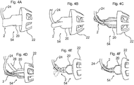
- the insertion member 2 similarly as previously described, protrudes from the rear end of the speaker unit 20. Accordingly, the earpiece 54 can be inserted into the ear canal by pressing the insertion member 2 that will transfer the force exerted to the insertion member, to the earpiece 54 comprising the dome 22.
- a wire 24 protrudes from the rear end of the speaker unit 20.
- Fig. 4B illustrates a schematic, side view of another hearing aid according to the disclosure having an integrated insertion member 2.
- the hearing aid basically corresponds to the one shown in Fig. 4A , however, the insertion member is slightly thinner than the one shown in Fig. 4A .
- Fig. 4C illustrates a schematic, side view of a further hearing aid according to the disclosure having an integrated insertion member 2.
- the hearing aid has an earpiece 54 provided with an open dome 22, into which a speaker unit 20 is attached.
- the insertion member 2 protrudes from the rear side of the speaker unit 20 and is provided with a receiving portion into which a wire 24 is attached. It can be seen that the insertion member 2 has a centrally arranged flexible portion that allows the insertion member 2 to be bent.
- Fig. 4D illustrates a schematic, side view of an even further hearing aid according to the disclosure having an integrated insertion member 2.
- the hearing aid basically corresponds to the one shown in Fig. 4D , however, an ear grip 28 is attached to the earpiece 54.
- Fig. 4E illustrates a schematic, side view of another hearing aid according to the disclosure having a detachably attached insertion member 2.
- the hearing aid comprises an earpiece 54 having an open dome 22 and a speaker unit 20 arranged therein.
- An insertion member 2 has been detachably attached to a wire 24 protruding from the rear end of the speaker unit 20.
- the insertion member 2 comprises two centrally arranged flexible portion allowing the insertion member 2 to be bent between the configuration indicated by the solid line and the configuration indicated by the dotted line.
- Fig. 4F illustrates a schematic, side view of a further hearing aid according to the disclosure having a detachably attached insertion member 2.
- the insertion member 2 corresponds to the one shown in Fig. 4C , however, the insertion member 2 is detachably attached to the wire 24 of the hearing aid.
- Fig. 5A illustrates a schematic view of a housing 52 of a behind-the-ear type hearing aid 56 according to the disclosure being arranged behind the pinna of a user.
- the user holds the housing 52 of the hearing aid 56 by the fingers 50.
- the hearing aid 56 comprises a speaker unit 20 and a dome 22 attached thereto.
- An ear grip 28 is attached to the speaker unit casing and an insertion member 2 is detachably attached to the wire 24.
- Fig. 5B illustrates a schematic view of the earpiece 54 of the hearing aid 56 shown in Fig. 5A being pressed into the ear canal 48 of the user. It can be seen, that the index finger 50 is used to press upon the insertion member 2 in order to force the earpiece 54 into the ear canal 48.
- Fig. 5C illustrates a schematic view of the hearing aid 56 shown in Fig. 5B when the earpiece 54 has been arranged deep into the ear canal 48 of the user.
- the wire 24 has been arranged behind the ear and the ear grip 28 is fixed to concha 46. It can be seen, that the insertion member 2 has been bent in order to allow the wire 24 to be bent. Accordingly, it is important to apply an insertion member 2 that can be bent.
- the insertion member 2 according to the disclosure comprises a flexible portion enabling the insertion member 2 to be bent.
- connection or “coupled” as used herein may include wirelessly connected or coupled.
- the term “and/or” includes any and all combinations of one or more of the associated listed items. The steps of any disclosed method are not limited to the exact order stated herein, unless expressly stated otherwise.
Priority Applications (1)
| Application Number | Priority Date | Filing Date | Title |
|---|---|---|---|
| EP17189363.9A EP3352479A1 (de) | 2017-09-05 | 2017-09-05 | Hörgerät mit flexiblem einführungselement |
Applications Claiming Priority (1)
| Application Number | Priority Date | Filing Date | Title |
|---|---|---|---|
| EP17189363.9A EP3352479A1 (de) | 2017-09-05 | 2017-09-05 | Hörgerät mit flexiblem einführungselement |
Publications (1)
| Publication Number | Publication Date |
|---|---|
| EP3352479A1 true EP3352479A1 (de) | 2018-07-25 |
Family
ID=59790995
Family Applications (1)
| Application Number | Title | Priority Date | Filing Date |
|---|---|---|---|
| EP17189363.9A Withdrawn EP3352479A1 (de) | 2017-09-05 | 2017-09-05 | Hörgerät mit flexiblem einführungselement |
Country Status (1)
| Country | Link |
|---|---|
| EP (1) | EP3352479A1 (de) |
Cited By (2)
| Publication number | Priority date | Publication date | Assignee | Title |
|---|---|---|---|---|
| EP4216575A1 (de) * | 2022-01-21 | 2023-07-26 | GN Hearing A/S | Verbinder und hörgerät mit diesem verbinder |
| US20230362527A1 (en) * | 2022-05-06 | 2023-11-09 | Bose Corporation | Raised feature on earbud body |
Citations (6)
| Publication number | Priority date | Publication date | Assignee | Title |
|---|---|---|---|---|
| EP1787493A1 (de) * | 2004-09-07 | 2007-05-23 | Widex A/S | Hörmuschel für ein hörapparat und hörapparat |
| US20090285428A1 (en) * | 2008-05-19 | 2009-11-19 | Gilgert Karl H | Ergonomic insertion tool for an open ear hearing aid |
| US20140150234A1 (en) * | 2012-11-30 | 2014-06-05 | iHear Medical, Inc. | Tool for insertion of canal hearing device into the ear canal |
| US20140376756A1 (en) * | 2013-06-20 | 2014-12-25 | Oticon A/S | Ear strap for a probe tube |
| US9161142B1 (en) * | 2012-01-17 | 2015-10-13 | Dennis Wagner | Push button insertion tool systems |
| US20170048630A1 (en) * | 2015-08-12 | 2017-02-16 | Jeffrey P. Szmanda | Apparatuses for controlling and positioning hearing aid components in ear canals |
-
2017
- 2017-09-05 EP EP17189363.9A patent/EP3352479A1/de not_active Withdrawn
Patent Citations (6)
| Publication number | Priority date | Publication date | Assignee | Title |
|---|---|---|---|---|
| EP1787493A1 (de) * | 2004-09-07 | 2007-05-23 | Widex A/S | Hörmuschel für ein hörapparat und hörapparat |
| US20090285428A1 (en) * | 2008-05-19 | 2009-11-19 | Gilgert Karl H | Ergonomic insertion tool for an open ear hearing aid |
| US9161142B1 (en) * | 2012-01-17 | 2015-10-13 | Dennis Wagner | Push button insertion tool systems |
| US20140150234A1 (en) * | 2012-11-30 | 2014-06-05 | iHear Medical, Inc. | Tool for insertion of canal hearing device into the ear canal |
| US20140376756A1 (en) * | 2013-06-20 | 2014-12-25 | Oticon A/S | Ear strap for a probe tube |
| US20170048630A1 (en) * | 2015-08-12 | 2017-02-16 | Jeffrey P. Szmanda | Apparatuses for controlling and positioning hearing aid components in ear canals |
Cited By (2)
| Publication number | Priority date | Publication date | Assignee | Title |
|---|---|---|---|---|
| EP4216575A1 (de) * | 2022-01-21 | 2023-07-26 | GN Hearing A/S | Verbinder und hörgerät mit diesem verbinder |
| US20230362527A1 (en) * | 2022-05-06 | 2023-11-09 | Bose Corporation | Raised feature on earbud body |
Similar Documents
| Publication | Publication Date | Title |
|---|---|---|
| US8718306B2 (en) | Hearing device with a detachably coupled earpiece | |
| EP2449797B1 (de) | Hörgerät mit lüftungserweiterung | |
| US20060067556A1 (en) | Universal earpiece | |
| US10791390B2 (en) | Flex-fit ear tip for headphones | |
| EP2601795B1 (de) | Lautsprechersystem für ein hörgerät | |
| EP3280158B1 (de) | Hörgerät | |
| US8442253B2 (en) | Hearing aid | |
| CN101218851A (zh) | 助听器和用于助听器的耳机 | |
| EP3226582A1 (de) | Hörgerät mit modularem verbindungsmittel | |
| CN102177730A (zh) | 用于拾取用户语音的系统 | |
| CN213602833U (zh) | 听力系统 | |
| EP3352479A1 (de) | Hörgerät mit flexiblem einführungselement | |
| EP3324644B1 (de) | Drahtloses hörgerät mit stabilisator zwischen tragus und antitragus | |
| JP2023096092A (ja) | 音響出力装置 | |
| EP2230859B1 (de) | Ohrstück | |
| EP3570565B1 (de) | Wachsfilterlösung für einen lautsprecher eines hörgeräts | |
| WO2002047431A1 (en) | Earphone system for mobile phone | |
| US10820125B2 (en) | Hearing aid with hinge less battery drawer | |
| EP4254986A1 (de) | Ohrstück für ein hörgerät und verfahren zur abnehmbaren montage eines ohrstücks eines hörgerätes | |
| EP4340387A1 (de) | Kopfhörer und verfahren zur durchführung eines befehls durch einen kopfhörer | |
| JP2021106357A (ja) | 電気音響変換器及び音響機器 |
Legal Events
| Date | Code | Title | Description |
|---|---|---|---|
| PUAI | Public reference made under article 153(3) epc to a published international application that has entered the european phase |
Free format text: ORIGINAL CODE: 0009012 |
|
| AK | Designated contracting states |
Kind code of ref document: A1 Designated state(s): AL AT BE BG CH CY CZ DE DK EE ES FI FR GB GR HR HU IE IS IT LI LT LU LV MC MK MT NL NO PL PT RO RS SE SI SK SM TR |
|
| AX | Request for extension of the european patent |
Extension state: BA ME |
|
| STAA | Information on the status of an ep patent application or granted ep patent |
Free format text: STATUS: THE APPLICATION IS DEEMED TO BE WITHDRAWN |
|
| 18D | Application deemed to be withdrawn |
Effective date: 20190126 |