EP3352176A1 - Scintillator panel and radiation detector - Google Patents
Scintillator panel and radiation detector Download PDFInfo
- Publication number
- EP3352176A1 EP3352176A1 EP16846282.8A EP16846282A EP3352176A1 EP 3352176 A1 EP3352176 A1 EP 3352176A1 EP 16846282 A EP16846282 A EP 16846282A EP 3352176 A1 EP3352176 A1 EP 3352176A1
- Authority
- EP
- European Patent Office
- Prior art keywords
- layer
- scintillator
- principal surface
- optical functional
- scintillator layer
- Prior art date
- Legal status (The legal status is an assumption and is not a legal conclusion. Google has not performed a legal analysis and makes no representation as to the accuracy of the status listed.)
- Granted
Links
- 230000005855 radiation Effects 0.000 title claims description 54
- 239000010410 layer Substances 0.000 claims abstract description 232
- 230000003287 optical effect Effects 0.000 claims abstract description 191
- 239000002346 layers by function Substances 0.000 claims abstract description 167
- 239000011241 protective layer Substances 0.000 claims abstract description 111
- 239000013078 crystal Substances 0.000 claims abstract description 110
- 239000000758 substrate Substances 0.000 claims abstract description 43
- 239000000463 material Substances 0.000 claims abstract description 22
- 238000006243 chemical reaction Methods 0.000 claims description 31
- 239000004033 plastic Substances 0.000 claims description 7
- 229920003023 plastic Polymers 0.000 claims description 7
- 229920005989 resin Polymers 0.000 description 10
- 239000011347 resin Substances 0.000 description 10
- 239000000853 adhesive Substances 0.000 description 4
- 230000001070 adhesive effect Effects 0.000 description 4
- 238000000034 method Methods 0.000 description 4
- 239000012466 permeate Substances 0.000 description 4
- 239000012790 adhesive layer Substances 0.000 description 3
- 230000007423 decrease Effects 0.000 description 3
- 230000008569 process Effects 0.000 description 3
- 229920000877 Melamine resin Polymers 0.000 description 2
- 239000011230 binding agent Substances 0.000 description 2
- 238000000151 deposition Methods 0.000 description 2
- 230000008021 deposition Effects 0.000 description 2
- 239000011521 glass Substances 0.000 description 2
- 238000003384 imaging method Methods 0.000 description 2
- 230000006872 improvement Effects 0.000 description 2
- 239000000049 pigment Substances 0.000 description 2
- 229920002803 thermoplastic polyurethane Polymers 0.000 description 2
- 229920002799 BoPET Polymers 0.000 description 1
- JOYRKODLDBILNP-UHFFFAOYSA-N Ethyl urethane Chemical compound CCOC(N)=O JOYRKODLDBILNP-UHFFFAOYSA-N 0.000 description 1
- 239000004640 Melamine resin Substances 0.000 description 1
- 239000004698 Polyethylene Substances 0.000 description 1
- XUIMIQQOPSSXEZ-UHFFFAOYSA-N Silicon Chemical compound [Si] XUIMIQQOPSSXEZ-UHFFFAOYSA-N 0.000 description 1
- 238000010521 absorption reaction Methods 0.000 description 1
- 230000000903 blocking effect Effects 0.000 description 1
- 230000006866 deterioration Effects 0.000 description 1
- 238000001035 drying Methods 0.000 description 1
- 230000000694 effects Effects 0.000 description 1
- 229920001971 elastomer Polymers 0.000 description 1
- 239000003822 epoxy resin Substances 0.000 description 1
- 239000000835 fiber Substances 0.000 description 1
- 238000005187 foaming Methods 0.000 description 1
- 238000010438 heat treatment Methods 0.000 description 1
- 229910010272 inorganic material Inorganic materials 0.000 description 1
- 239000011147 inorganic material Substances 0.000 description 1
- 239000007791 liquid phase Substances 0.000 description 1
- 238000009607 mammography Methods 0.000 description 1
- JDSHMPZPIAZGSV-UHFFFAOYSA-N melamine Chemical compound NC1=NC(N)=NC(N)=N1 JDSHMPZPIAZGSV-UHFFFAOYSA-N 0.000 description 1
- 239000000203 mixture Substances 0.000 description 1
- 239000013307 optical fiber Substances 0.000 description 1
- 238000002161 passivation Methods 0.000 description 1
- 230000002093 peripheral effect Effects 0.000 description 1
- 230000035699 permeability Effects 0.000 description 1
- 239000002985 plastic film Substances 0.000 description 1
- 229920000647 polyepoxide Polymers 0.000 description 1
- -1 polyethylene Polymers 0.000 description 1
- 229920000573 polyethylene Polymers 0.000 description 1
- 229920001296 polysiloxane Polymers 0.000 description 1
- 239000000843 powder Substances 0.000 description 1
- 238000003825 pressing Methods 0.000 description 1
- 230000002265 prevention Effects 0.000 description 1
- 230000004044 response Effects 0.000 description 1
- 238000007789 sealing Methods 0.000 description 1
- 229910052710 silicon Inorganic materials 0.000 description 1
- 239000010703 silicon Substances 0.000 description 1
- 230000001629 suppression Effects 0.000 description 1
- 238000001771 vacuum deposition Methods 0.000 description 1
Images


Classifications
-
- G—PHYSICS
- G01—MEASURING; TESTING
- G01T—MEASUREMENT OF NUCLEAR OR X-RADIATION
- G01T1/00—Measuring X-radiation, gamma radiation, corpuscular radiation, or cosmic radiation
- G01T1/16—Measuring radiation intensity
- G01T1/20—Measuring radiation intensity with scintillation detectors
- G01T1/2002—Optical details, e.g. reflecting or diffusing layers
-
- G—PHYSICS
- G01—MEASURING; TESTING
- G01T—MEASUREMENT OF NUCLEAR OR X-RADIATION
- G01T1/00—Measuring X-radiation, gamma radiation, corpuscular radiation, or cosmic radiation
- G01T1/16—Measuring radiation intensity
- G01T1/20—Measuring radiation intensity with scintillation detectors
-
- G—PHYSICS
- G01—MEASURING; TESTING
- G01T—MEASUREMENT OF NUCLEAR OR X-RADIATION
- G01T1/00—Measuring X-radiation, gamma radiation, corpuscular radiation, or cosmic radiation
- G01T1/16—Measuring radiation intensity
- G01T1/20—Measuring radiation intensity with scintillation detectors
- G01T1/2006—Measuring radiation intensity with scintillation detectors using a combination of a scintillator and photodetector which measures the means radiation intensity
-
- G—PHYSICS
- G01—MEASURING; TESTING
- G01T—MEASUREMENT OF NUCLEAR OR X-RADIATION
- G01T1/00—Measuring X-radiation, gamma radiation, corpuscular radiation, or cosmic radiation
- G01T1/16—Measuring radiation intensity
- G01T1/20—Measuring radiation intensity with scintillation detectors
- G01T1/202—Measuring radiation intensity with scintillation detectors the detector being a crystal
- G01T1/2023—Selection of materials
-
- G—PHYSICS
- G21—NUCLEAR PHYSICS; NUCLEAR ENGINEERING
- G21K—TECHNIQUES FOR HANDLING PARTICLES OR IONISING RADIATION NOT OTHERWISE PROVIDED FOR; IRRADIATION DEVICES; GAMMA RAY OR X-RAY MICROSCOPES
- G21K4/00—Conversion screens for the conversion of the spatial distribution of X-rays or particle radiation into visible images, e.g. fluoroscopic screens
- G21K2004/02—Conversion screens for the conversion of the spatial distribution of X-rays or particle radiation into visible images, e.g. fluoroscopic screens characterised by the external panel structure
-
- G—PHYSICS
- G21—NUCLEAR PHYSICS; NUCLEAR ENGINEERING
- G21K—TECHNIQUES FOR HANDLING PARTICLES OR IONISING RADIATION NOT OTHERWISE PROVIDED FOR; IRRADIATION DEVICES; GAMMA RAY OR X-RAY MICROSCOPES
- G21K4/00—Conversion screens for the conversion of the spatial distribution of X-rays or particle radiation into visible images, e.g. fluoroscopic screens
- G21K2004/10—Conversion screens for the conversion of the spatial distribution of X-rays or particle radiation into visible images, e.g. fluoroscopic screens with a protective film
Definitions
- An aspect of the invention relates to a scintillator panel and a radiation detector.
- Patent Literature 1 discloses an X-ray detector.
- the X-ray detector includes a photoelectric conversion substrate, a fluorescence conversion film formed on a surface of the photoelectric conversion substrate and a light reflecting layer formed on the photoelectric conversion substrate and the fluorescence conversion film.
- the fluorescence conversion film is formed with a columnar crystal structure in which a plurality of columnar crystals are formed in an in-plane direction of the photoelectric conversion substrate.
- the light reflecting layer seals the fluorescence conversion film by causing a peripheral portion thereof to adhere to the photoelectric conversion substrate.
- the light reflecting layer is formed of a mixture of an adhesive material having fluidity and a powder of an inorganic material having a higher refraction index than the adhesive material.
- Patent Literature 1 Japanese Unexamined Patent Publication No. 2009-25258
- the X-ray detector achieves prevention of deterioration of the fluorescence conversion film by blocking moisture using the light reflecting layer.
- the X-ray detector achieves improvement in X-ray resolution by preventing the light reflecting layer from permeating the fluorescence conversion film.
- the light reflecting layer is deformed so as to follow tips by flowing of the adhesive material and fills a space between the tips of neighboring columnar crystals.
- the light reflecting layer may also permeate between neighboring columnar crystals on a base side of the columnar crystals. In this case, there is concern that an X-ray resolution and an optical output will decrease due to leakage of visible light from the columnar crystals to the light reflecting layer.
- An object of an aspect of the invention is to provide a scintillator panel and a radiation detector that can improve a resolution and an optical output.
- a scintillator panel that converts radiation into scintillation light
- the scintillator panel including: a substrate that includes a principal surface and has transparency with respect to the scintillation light; a scintillator layer that is disposed on the principal surface; a frame member that is disposed on the principal surface so as to surround the scintillator layer when viewed in a direction intersecting the principal surface; a protective layer that is disposed on the principal surface and the scintillator layer and is fixed to the frame member so as to seal the scintillator layer; a sheet-shaped optical functional layer that is disposed between the scintillator layer and the protective layer; and an elastic member that is interposed between the optical functional layer and the protective layer and is elastically deformed, wherein a height of the frame member from the principal surface is larger than a height of the scintillator layer from the principal surface, wherein the scintillator layer includes a plurality of columnar crystals
- the scintillator layer including a plurality of columnar crystals is disposed on the principal surface of the substrate and is sealed by the protective layer.
- the sheet-shaped optical functional layer is disposed between the scintillator layer and the protective layer, and the elastic member is disposed between the optical functional layer and the protective layer.
- the elastic member is interposed between the optical functional layer and the protective layer and is elastically deformed.
- the optical functional layer is pressed to the scintillator layer by the elastic force of the elastic member and comes in contact with the scintillator layer in a plurality of regions including the tips of the columnar crystals of the scintillator layer.
- the sheet-shaped optical functional layer is used in the scintillator panel. Accordingly, it is possible to prevent the optical functional layer from filling a gap between the tips of the neighboring columnar crystals or permeating between the columnar crystals. Since the optical functional layer is pressed to the scintillator layer by the elastic force of the elastic member, it is possible to prevent the optical functional layer from being separated from the tips of the columnar crystals. Accordingly, it is possible to prevent scintillation light from leaking from the columnar crystals. As a result, it is possible to improve a resolution and an optical output.
- the protective layer is fixed to the frame member which is higher (thicker) than the scintillator layer. Accordingly, for example, by using the protective layer having a flat plate shape, a space corresponding to a difference in the height between the frame member and the scintillator layer is formed between the scintillator layer and the protective layer. Accordingly, by disposing the optical functional layer and the elastic member in the space, it is possible to easily and satisfactorily realize the above-mentioned configuration and thus to improve a resolution and an optical output.
- the elastic member may have a sheet shape extending along the principal surface.
- the elastic member may include foamed plastic.
- the optical functional layer can be pressed uniformly along the principal surface of the substrate using the elastic member.
- the elastic member may be formed integrally with the optical functional layer or the protective layer.
- the optical functional layer can be easily configured to be pressed to the scintillator layer using the elastic member.
- the tip of each columnar crystal may be flattened. Even when the tips of the columnar crystals are flattened in this way, the optical functional layer can be prevented from filling a gap between the tips of the neighboring columnar crystals or permeating between the columnar crystals, and thus it is possible to improve a resolution and an optical output.
- a radiation detector including: a substrate that includes a principal surface and a plurality of photoelectric conversion elements formed on the principal surface; a scintillator layer that is disposed on the photoelectric conversion elements and that converts radiation into scintillation light; a frame member that is disposed on the principal surface so as to surround the scintillator layer when viewed in a direction intersecting the principal surface; a protective layer that is disposed on the principal surface and the scintillator layer and is fixed to the frame member so as to seal the scintillator layer; a sheet-shaped optical Functional layer that is disposed between the scintillator layer and the protective layer; and an elastic member that is interposed between the optical functional layer and the protective layer and is elastically deformed, wherein a height of the frame member from the principal surface is larger than a height of the scintillator layer from the principal surface, wherein the scintillator layer includes a plurality of columnar crystals of a scintill
- the scintillator layer including a plurality of columnar crystals is disposed on the principal surface of the substrate including a plurality of photoelectric conversion elements and is sealed by the protective layer.
- the sheet-shaped optical functional layer is disposed between the scintillator layer and the protective layer, and the elastic member is disposed between the optical functional layer and the protective layer.
- the elastic member is interposed between the optical functional layer and the protective layer and is elastically deformed.
- the optical functional layer is pressed to the scintillator layer by the elastic force of the elastic member and comes in contact with the scintillator layer in a plurality of regions including the tips of the columnar crystals of the scintillator layer.
- the sheet-shaped optical functional layer is used. Accordingly, it is possible to prevent the optical functional layer from filling a gap between the tips of the neighboring columnar crystals or permeating between the columnar crystals. Since the optical functional layer is pressed to the scintillator layer by the elastic force of the elastic member, it is possible to prevent the optical functional layer from being separated from the tips of the columnar crystals. Accordingly, it is possible to prevent scintillation light from leaking from the columnar crystals. As a result, it is possible to improve a resolution and an optical output.
- the protective layer is fixed to the frame member which is higher (thicker) than the scintillator layer. Accordingly, for example, by using the protective layer having a flat plate shape, a space corresponding to a difference in the height between the frame member and the scintillator layer is formed between the scintillator layer and the protective layer. Accordingly, by disposing the optical functional layer and the elastic member in the space, it is possible to easily and satisfactorily realize the above-mentioned configuration and thus to improve a resolution and an optical output.
- the elastic member may have a sheet shape extending along the principal surface.
- the elastic member may include foamed plastic.
- the optical functional layer can be pressed uniformly along the principal surface of the substrate using the elastic member.
- the elastic member may be formed integrally with the optical functional layer or the protective layer.
- the optical functional layer can be easily configured to be pressed to the scintillator layer using the elastic member.
- the tip of each columnar crystal may be flattened. Even when the tips of the columnar crystals are flattened in this way, the optical functional layer can be prevented from filling a gap between the tips of the neighboring columnar crystals or permeating between the columnar crystals, and thus it is possible to improve a resolution and an optical output.
- a scintillator panel that converts radiation into scintillation light
- the scintillator panel including: a substrate that includes a principal surface and has transparency with respect to the scintillation light; a scintillator layer that is disposed on the principal surface; a frame member that is disposed on the principal surface so as to surround the scintillator layer when viewed in a direction intersecting the principal surface; a protective layer that is disposed on the principal surface and the scintillator layer and is fixed to the frame member so as to seal the scintillator layer; and a hard optical functional layer that is formed integrally on a surface of the protective layer facing the scintillator layer, wherein a height of the frame member from the principal surface is larger than a height of the scintillator layer from the principal surface, wherein the scintillator layer includes a plurality of columnar crystals of a scintillator material, and wherein the optical functional layer is pressed
- the scintillator layer including a plurality of columnar crystals is disposed on the principal surface of the substrate and is scaled by the protective layer.
- the hard optical functional layer is formed integrally on the surface of the protective layer facing the scintillator layer.
- the optical functional layer is pressed to the scintillator layer in the state where the protective layer is fixed to the frame member. Accordingly, the optical functional layer comes in contact with the scintillator layer in a plurality of regions including the tips of the columnar crystals of the scintillator layer.
- the hard optical functional layer formed integrally with the protective layer is used. Accordingly, it is possible to prevent the optical functional layer from filling a gap between the tips of the neighboring columnar crystals or permeating between the columnar crystals. Since the optical functional layer is pressed to the scintillator layer by fixation to the protective layer, it is possible to prevent the optical functional layer from being separated from the tips of the columnar crystals. Accordingly, it is possible to prevent scintillation light from leaking from the columnar crystals. As a result, it is possible to improve a resolution and an optical output.
- the protective layer is fixed to the frame member which is higher (thicker) than the scintillator layer. Accordingly, for example, by using the protective layer having a flat plate shape, a space corresponding to a difference in the height between the frame member and the scintillator layer is formed between the scintillator layer and the protective layer. Accordingly, by forming the optical functional layer along the space, it is possible to easily and satisfactorily realize the above-mentioned configuration and thus to improve a resolution and an optical output.
- the hard optical functional layer is an optical functional layer that is formed, for example, by curing a material including a resin and thus has hardness corresponding to hardness of a cured resin.
- a radiation detector including: a substrate that includes a principal surface and a plurality of photoelectric conversion elements formed on the principal surface; a scintillator layer that is disposed on the photoelectric conversion elements and that converts radiation into scintillation light; a frame member that is disposed on the principal surface so as to surround the scintillator layer when viewed in a direction intersecting the principal surface; a protective layer that is disposed on the principal surface and the scintillator layer and is fixed to the frame member so as to seal the scintillator layer; and a hard optical functional layer that is formed integrally on a surface of the protective layer facing the scintillator layer, wherein a height of the frame member from the principal surface is larger than a height of the scintillator layer from the principal surface, wherein the scintillator layer includes a plurality of columnar crystals of a scintillator material, and wherein the optical functional layer is pressed to the scintillator
- the scintillator layer including a plurality of columnar crystals is disposed on the principal surface of the substrate including a plurality of photoelectric conversion elements and is sealed by the protective layer.
- the hard optical functional layer is formed integrally on the surface of the protective layer facing the scintillator layer.
- the optical functional layer is pressed to the scintillator layer in the state where the protective layer is fixed to the frame member. Accordingly, the optical functional layer comes in contact with the scintillator layer in a plurality of regions including the tips of the columnar crystals of the scintillator layer.
- the hard optical functional layer formed integrally with the protective layer is used. Accordingly, it is possible to prevent the optical functional layer from filling a gap between the tips of the neighboring columnar crystals or permeating between the columnar crystals. Since the optical functional layer is pressed to the scintillator layer by fixation to the protective layer, it is possible to prevent the optical functional layer from being separated from the tips of the columnar crystals. Accordingly, it is possible to prevent scintillation light from leaking from the columnar crystals. As a result, it is possible to improve a resolution and an optical output.
- the protective layer is fixed to the frame member which is higher (thicker) than the scintillator layer. Accordingly, for example, by using the protective layer having a flat plate shape, a space corresponding to a difference in the height between the frame member and the scintillator layer is formed between the scintillator layer and the protective layer. Accordingly, by forming the optical functional layer along the space, it is possible to easily and satisfactorily realize the above-mentioned configuration and thus to improve a resolution and an optical output.
- a scintillator panel serves to convert radiation such as X-rays into scintillation light such as visible light.
- the scintillator panel according to the following embodiment can be used, for example, as a radiation imaging device in a mammography device, a mass chest diagnostic device, a CT device, a dental oral imaging device, or a radiographic camera.
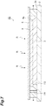
- FIG. 1 is a sectional view of the scintillator panel according to this embodiment.
- FIG. 2 is a plan view of the scintillator panel illustrated in FIG. 1 .
- the scintillator panel 1 includes a substrate 2, a scintillator layer 3, a frame member 4, a protective layer 5, an optical functional layer 6, and an elastic member 7.
- the substrate 2 includes a principal surface 2s.
- the substrate 2 has, for example, a rectangular plate shape.
- the substrate 2 has transparency with respect to scintillation light which is generated in the scintillator layer 3.
- the thickness of the substrate 2 is, for example, about 2.0 mm.
- the substrate 2 is formed of, for example, a fiber optic plate (FOP: an optical device formed by binding a plurality of optical fibers (for example, J5734 made by Hamamatsu Photonics K.K.)).
- FOP fiber optic plate
- the scintillator layer 3 generates scintillation light such as visible light in response to incidence of radiation R such as X-rays.
- the scintillator layer 3 is disposed on the principal surface 2s of the substrate 2.
- the scintillator layer 3 is formed in a rectangular area of the principal surface 2s when viewed from a direction intersecting (for example, perpendicular to) the principal surface 2s.
- An outer edge portion of the scintillator layer 3 has an inclined portion such that the thickness of the scintillator layer 3 decreases from the center of the scintillator layer 3 to the edge. Accordingly, a sectional shape of the scintillator layer 3 as a whole is, for example, a trapezoidal shape.
- the thickness of the scintillator layer 3 (the thickness other than the inclined portion) is, for example, about 600 ⁇ m.
- the scintillator layer 3 includes a plurality of columnar crystals 30 of a scintillator material (see FIG. 3(b) ).
- the scintillator material is, for example, a material containing CsI as a major component such as CsI:Tl.
- the scintillator layer 3 is formed, for example, by causing the columnar crystals 30 to grow on the principal surface 2s of the substrate 2 using a vacuum deposition method or the like.
- the frame member 4 is disposed on the principal surface 2s so as to surround the scintillator layer 3 when viewed from a direction intersecting the principal surface 2s of the substrate 2.
- the frame member 4 has, for example, a rectangular ring shape.
- the height H4 of the frame member 4 from the principal surface 2s is larger than the height H3 (thickness) of the scintillator layer 3 from the principal surface 2s.
- the frame member 4 is interposed between the principal surface 2s and the protective layer 5 and causes the principal surface 2s and the protective layer 5 to adhere to each other.
- the principal surface 2s, the frame member 4, and the protective layer 5 form a space in which the scintillator layer 3, the optical functional layer 6, and the elastic member 7 are disposed.
- the frame member 4 is bonded to the principal surface 2s and the protective layer 5 so as to at least liquid-tightly (and air-tightly) seal the space.
- the frame member 4 is formed of, for example, a resin having low moisture permeability such as an epoxy resin.
- the protective layer 5 is disposed on the principal surface 2s and the scintillator layer 3.
- the protective layer 5 is disposed so as to cover the scintillator layer 3 and the frame member 4 when viewed from the direction intersecting the principal surface 2s.
- the protective layer 5 has, for example, a rectangular flat plate shape extending along the principal surface 2s.
- the protective layer 5 transmits radiation R.
- the thickness of the protective layer 5 ranges from 0.5 mm to 2.0 mm.
- the protective layer 5 is, for example, a glass plate of chemically reinforced glass.
- the protective layer 5 is fixed (bonded) to the frame member 4 so as to at least fluid-tightly seal the scintillator layer 3. Moisture-proofing of the scintillator layer 3 is realized by this sealing structure.
- the optical functional layer 6 is disposed between the scintillator layer 3 and the protective layer 5.
- the optical functional layer 6 has a sheet shape. That is, the optical functional layer 6 does not have fluidity.
- the optical functional layer 6 has a rectangular sheet shape extending along the principal surface 2s.
- the optical functional layer 6 covers the scintillator layer 3 when viewed from the direction intersecting the principal surface 2s.
- the optical functional layer 6 transmits radiation R.
- the optical functional layer 6 is, for example, a light reflecting layer that reflects scintillation light generated in the scintillator layer 3 or a light absorbing layer that absorbs the scintillation light.
- the thickness of the optical functional layer 6 is, for example, about 100 ⁇ m.
- the optical functional layer 6 can include a layer formed of a pigment and a binder resin.
- the optical functional layer 6 is, for example, a PET film.
- the elastic member (elastic layer) 7 is disposed between the optical functional layer 6 and the protective layer 5.
- the elastic member 7 has, for example, a sheet shape extending along the principal surface 2s.
- the elastic member 7 is disposed on the optical functional layer 6 so as to cover at least the scintillator layer 3 when viewed from the direction intersecting the principal surface 2s.
- the elastic member 7 transmits radiation R.
- the elastic member 7 is interposed between the optical functional layer 6 and the protective layer 5 and is clastically deformed (that is, is compressed in the direction intersecting the principal surface 2s). Accordingly, the elastic member 7 presses the optical functional layer 6 to the scintillator layer 3 by an elastic force thereof. That is, the elastic member 7 is a pressure applying layer that applies a pressure to the optical functional layer 6.
- the thickness of the elastic member 7 ranges from 100 ⁇ m to 1000 ⁇ m.
- the material of the elastic member 7 is, for example, a plastic such as a polyethylene, a urethane resin, or a melamine resin, a rubber, or a silicone gel.
- the elastic member 7 is a foamed plastic sheet formed by foaming the plastic, a urethane mat (a urethane resin sheet), a silicon gel sheet, a melamine sponge sheet, or a sheet-shaped bubble buffer material.
- FIG. 3 is an enlarged sectional view illustrating a part of the scintillator panel illustrated in FIG. 1 .
- FIG. 3(a) illustrates an area Ra in FIG. 1
- FIG. 3(b) illustrates an area Rb in FIG. 1 .
- the elastic member 7 is bonded to the optical functional layer 6 by an adhesive layer 8 and is integrated with the optical functional layer 6.
- the adhesive layer 8 is, for example, a resin having adhesiveness.
- the columnar crystals 30 of the scintillator layer 3 are bonded to the principal surface 2s of the substrate 2 at bases thereof.
- Each columnar crystal 30 includes a columnar portion 31 and a tapered portion 32.
- the columnar portion 31 includes a base on the principal surface 2s side of the columnar crystal 30.
- the columnar portion 31 extends in the direction intersecting the principal surface 2s from the principal surface 2s.
- the tapered portion 32 includes a tip 30t of the columnar crystal 30.
- the tapered portion 32 is formed integrally with the columnar portion 31.
- the tapered portion 32 has a tapered shape which is reduced as it goes away from the principal surface 2s.
- the sectional shape of the tapered portion 32 is, for example, a triangular shape.
- the columnar crystals 30 are separated from each other. That is, a gap is formed between neighboring columnar crystals 30. More specifically, between the neighboring columnar crystals 30, a gap is formed between side surfaces 31s of the columnar portions 31 and between side surfaces 32s of the tapered portions 32.
- the elastic member 7 presses the optical functional layer 6 to the scintillator layer 3 by an elastic force thereof. That is, the optical functional layer 6 is pressed by the elastic force of the elastic member 7 and comes in contact with the scintillator layer 3.
- the optical functional layer 6 comes in contact with the tips 30t of the plurality of columnar crystals 30.
- the tips 30t of the columnar crystals 30 are separated and independent from each other. Accordingly, the optical functional layer 6 comes in contact with the scintillator layer 3 in a plurality of independent areas including the tips 30t of the plurality of columnar crystals 30 (that is, comes in contact at multiple points).
- the optical functional layer 6 does not fill the gaps between the neighboring columnar crystals 30.
- the optical functional layer 6 comes in contact with the scintillator layer 3 so as to maintain the gaps between the neighboring columnar crystals 30.
- the sheet-shaped optical functional layer 6 is deformed to follow the shapes of the tips 30t of the columnar crystals 30, but comes in contact with only a part of the side surfaces 32s of the tapered portions 32 on the tip 30t side. Accordingly, most of the side surface 32s of each tapered portion 32 on the columnar portion 31 side does not come in contact with the optical functional layer 6 and contact with an air layer having a lower refraction index than the optical functional layer 6 and the scintillator layer 3 is maintained.
- the optical functional layer 6 does not permeate the gaps between the side surfaces 31s of the columnar portions 31. Accordingly, the overall side surface 31s of each columnar portion 31 does not come in contact with the optical functional layer 6 and contact with an air layer is maintained.
- the optical functional layer when the optical functional layer is formed by applying a material having fluidity (a liquid-phase material) onto the scintillator layer 3, the optical functional layer fills the gaps between the side surfaces 32s of the tapered portions 32 and permeates the gaps between the side surfaces 31s of the columnar portions 31. Accordingly, the entire side surface 32s of each tapered portion 32 and at least a part of the side surface 31s of each columnar portion 31 comes in contact with the optical functional layer having a higher refraction index than the air layer.
- a material having fluidity a liquid-phase material
- the scintillator layer 3 including a plurality of columnar crystals 30 is disposed on the principal surface 2s of the substrate 2 and is sealed by the protective layer 5 and the frame member 4.
- the sheet-shaped optical functional layer 6 is disposed between the scintillator layer 3 and the protective layer 5.
- the elastic member 7 is disposed between the optical functional layer 6 and the protective layer 5.
- the elastic member 7 is interposed between the optical functional layer 6 and the protective layer 5 and is elastically deformed (compressed).
- the optical functional layer 6 is pressed to the scintillator layer 3 by the elastic force of the elastic member 7. Accordingly, the optical functional layer 6 comes in contact with the scintillator layer 3 in a plurality of independent regions including the tips 30t of the columnar crystals 30.
- the sheet-shaped optical functional layer 6 is used in the scintillator panel 1. Accordingly, it is possible to prevent the optical functional layer 6 from filling the gap between the tapered portions 32 of the neighboring columnar crystals 30 or permeating the gaps between the columnar portions 31 of the columnar crystals 30. Since the optical functional layer 6 is pressed to the scintillator layer 3 by the elastic force of the elastic member 7, it is possible to prevent the optical functional layer 6 from being separated from the tips 30t of the columnar crystals 30. Accordingly, it is possible to prevent scintillation light from leaking from the columnar crystals 30. As a result, it is possible to improve a resolution and an optical output.
- the protective layer 5 is fixed to the frame member 4 which is higher (thicker) than the scintillator layer 3. Accordingly, for example, by using the protective layer 5 having a flat plate shape, a space formed by a difference in the height between the frame member 4 and the scintillator layer 3 is formed between the scintillator layer 3 and the protective layer 5. Accordingly, by disposing the optical functional layer 6 and the elastic member 7 in the space, it is possible to easily and satisfactorily realize the above-mentioned configuration and thus to improve a resolution and an optical output.
- the elastic member 7 may have a sheet shape extending along the principal surface 2s of the substrate 2.
- the elastic member 7 may include, for example, foamed plastic.
- the optical functional layer 6 can be pressed uniformly along the principal surface 2s using the elastic member 7.
- the elastic member 7 is formed integrally with the optical functional layer 6. Accordingly, the optical functional layer 6 can be easily configured to be pressed to the scintillator layer 3 using the elastic member 7.
- the thickness of the elastic member 7 can be set, for example, to range from 100 ⁇ m to 1000 ⁇ m. When the thickness of the elastic member 7 is equal to or greater than 100 ⁇ m, an elastic force sufficient for pressing the optical functional layer 6 to the scintillator layer 3 to come in contact with the scintillator layer 3 can be obtained. When the thickness of the elastic member 7 is equal to or less than 1000 ⁇ m, it is possible to prevent an increase in size (an increase in thickness) of the scintillator panel 1.
- the thickness of the elastic member 7 is set to range from 100 ⁇ m to 1000 ⁇ m, a decrease in size (suppression of an increase in thickness) of the scintillator panel 1 and improvement of a resolution and an optical output can be made to coexist.
- FIG. 4 is a sectional view of a scintillator panel according to a modified example.
- FIG. 5 is an enlarged sectional view illustrating a part of the scintillator panel illustrated in FIG. 4 .
- FIG. 5(a) illustrates an area Ra in FIG. 4 .
- FIG 5(b) illustrates an area Rb in FIG 4 .
- the scintillator panel 1A is different from the scintillator panel 1, in that a scintillator layer 3A is provided instead of the scintillator layer 3 and the elastic member 7 is integrated with the protective layer 5.
- the scintillator layer 3A is different from the scintillator layer 3, in that columnar crystals 30A are included instead of the columnar crystals 30.
- the columnar crystals 30A are different from the columnar crystals 30, in that a tapered portion 32A is provided instead of the tapered portion 32.
- Each tapered portion 32A includes a tip 30t.
- the tapered portion 32A is integrally formed with the columnar portion 31.
- the tapered portion 32A has a tapered shape which is reduced as it is separated away from the principal surface 2s.
- a sectional shape of the tapered portion 32A is, for example, trapezoidal shape.
- the tips 30t of the columnar crystals 30A are flattened, for example, by at least one of a pressurizing process, a heating process, an energy ray irradiation process of a laser beam or the like, and a grind process. That is, the tip 30t of each columnar crystal 30A is a flat surface which is defined by an edge portion of the side surface 32s of the tapered portion 32A.
- the elastic member 7 is bonded to the protective layer 5 by the adhesive layer 8 and is integrated with the protective layer 5.
- the optical functional layer 6 is pressed by the elastic force of the elastic member 7 and comes in contact with the scintillator layer 3A.
- the optical functional layer 6 comes in contact with the tips 30t of the plurality of columnar crystals 30A. That is, the optical functional layer 6 comes in contact with the scintillator layer 3A in a plurality of independent flat regions including the tips 30t of the plurality of columnar crystals 30A (that is, comes in contact at multiple points).
- the optical functional layer 6 does not fill the gaps between the neighboring columnar crystals 30A. That is, the optical functional layer 6 comes in contact with the scintillator layer 3A so as to maintain the gaps between the neighboring columnar crystals 30A. More specifically, the optical functional layer 6 comes in contact with only the flat surface (the tips 30t) which is defined the side surface 32s of the tapered portion 32A. Accordingly, the most part of the side surface 32s of each tapered portion 32A does not come in contact with the optical functional layer 6 and contact with an air layer having a lower refraction index than the optical functional layer 6 and the scintillator layer 3A is maintained. The optical functional layer 6 does not permeate the gaps between the side surfaces 31s of the columnar portions 31. Accordingly, the overall side surface 31s of each columnar portion 31 does not come in contact with the optical functional layer 6 and maintains contact with an air layer.
- the elastic member 7 is formed integrally with the protective layer 5. Accordingly, the optical functional layer 6 can be easily configured to be pressed to the scintillator layer 3A using the elastic member 7.
- the aspect of the invention is not limited to the scintillator panels 1 and 1A.
- the scintillator panels 1 and 1A can be arbitrarily modified or be applied to another configuration without changing the gist of the appended claims.
- a scintillator layer 3B can be used instead of the scintillator layer 3.
- the scintillator layer 3B is different from the scintillator layer 3, in that columnar crystals 30B are provided instead of the columnar crystals 30.
- the columnar crystal 30B is different from the columnar crystal 30, in that the tip 30t is flattened.
- the columnar crystal 30B is formed by flattening the tip 30t so as to remove the entire tapered portion 32 of the columnar crystal 30. That is, the columnar crystal 30B includes only the columnar portion 31.
- the sheet-shaped optical functional layer 6 is pressed by the elastic force of the elastic member 7 and comes in contact with only flat surfaces (the tips 30t) which are defined by edges of the side surfaces 31s of the columnar portions 31. Accordingly, similarly to a case in which the scintillator layer 3 is used, it is possible to improve a resolution and an optical output.
- the elastic member 7 may be integrated with the protective layer 5.
- the elastic member 7 may be integrated with the optical functional layer 6.
- the scintillator layer 3B can be used instead of the scintillator layer 3A.
- the scintillator panel according to the aspect of the invention can be applied as a scintillator panel 1C illustrated in FIG. 7 .
- the scintillator panel 1C is different from the scintillator panel 1, in that an optical functional layer 9 is provided instead of the optical functional layer 6 and the elastic member 7 is not provided.
- the optical functional layer 9 is disposed between the scintillator layer 3 and the protective layer 5.
- the optical functional layer 9 is formed on a surface 5s of the protective layer 5 facing the scintillator layer 3.
- the optical functional layer 9 can be formed, for example, by disposing a resin layer formed of a pigment and a binder resin having optical functions such as reflection or absorption on the surface 5s of the protective layer 5 and drying and curing the resin layer. Accordingly, the optical functional layer 9 is hard. That is, the optical functional layer 9 does not have fluidity.
- the optical functional layer 9 is formed integrally with the surface 5s of the protective layer 5.
- the hard optical functional layer 9 is an optical functional layer that has hardness corresponding to the hardness of the resin cured by curing a material including a resin to form the optical functional layer as described above.
- the optical functional layer 9 is pressed to the scintillator layer 3 in a state where the protective layer 5 is fixed to the frame member 4 (by fixing the protective layer to the frame member). Accordingly, the optical functional layer 9 comes in contact with the scintillator layer 3. Particularly, the optical functional layer 9 comes in contact with the scintillator layer 3 (that is, comes in contact at multiple points) in a plurality of independent regions including the tips 30t of the plurality of columnar crystals 30.
- the hard optical functional layer 9 is integrally formed on the surface 5s of the protective layer 5 facing the scintillator layer 3.
- the optical functional layer 9 is interposed between the protective layer 5 and the scintillator layer 3 and is pressed to the scintillator layer 3 in the state where the protective layer 5 is fixed to the frame member 4. Accordingly, the optical functional layer 9 comes in contact with the scintillator layer 3 in a plurality of regions including the tips 30t of the columnar crystals 30 of the scintillator layer 3.
- the hard optical functional layer 9 formed integrally with the protective layer 5 is used. Accordingly, it is possible to prevent the optical functional layer 5 from filling the gap between the tips 30t of the neighboring columnar crystals 30 or permeating the space between the columnar crystals 30. Since the optical functional layer 9 is pressed to the scintillator layer 3 by fixation to the protective layer 5, it is possible to prevent the optical functional layer 9 from being separated from the tips 30t of the columnar crystals 30. Accordingly, it is possible to prevent scintillation light from leaking from the columnar crystals 30. As a result, it is possible to improve a resolution and an optical output. That is, the same characteristics as in the combination of the protective layer 5, the optical functional layer 6, and the elastic member 7 can be obtained in the protective layer 5 and the optical functional layer 9.
- the scintillator layer 3A or the scintillator layer 3B may be used instead of the scintillator layer 3.
- a radiation detector can be constructed by using a sensor panel having photoelectric conversion elements (for example, a TFT panel or a CMOS image sensor panel) as a substrate. An example of the radiation detector will be described below.
- FIG. 8 is a sectional view of a radiation detector according to the embodiment.
- a radiation detector 1D is different from the scintillator panel 1, in that a substrate 2D which is a sensor panel is provided instead of the substrate 2.
- the substrate (sensor panel) 2D includes a principal surface 2s and a plurality of photoelectric conversion elements 10 formed on the principal surface 2s. More specifically, the substrate 2D includes a plate-shaped base portion 2p including the principal surface 2s.
- the photoelectric conversion elements 10 are two-dimensionally arranged along the principal surface 2s.
- the scintillator layer 3 is formed on the principal surface 2s and the photoelectric conversion elements 10, for example, by deposition.
- a film portion 11 such as a passivation film or a planarization film is formed on the principal surface 2s and the photoelectric conversion elements 10.
- the scintillator layer 3 is disposed on the principal surface 2s and the photoelectric conversion elements 10 with the film portion 11 interposed therebetween.
- the scintillator layer 3 is optically coupled to the photoelectric conversion elements 10. Accordingly, the photoelectric conversion elements 10 receives scintillation light generated in the scintillator layer 3 and outputs an electric signal corresponding to the scintillation light. The electric signal is taken out by a wire or the like which is not illustrated. Accordingly, the radiation detector 1D detects radiation R.
- the radiation detector 1D achieves the same advantages as the advantages achieved by the scintillator panel 1. More specifically, in the radiation detector 1D, the scintillator layer 3 including a plurality of columnar crystals 30 is disposed on the principal surface 2s of the substrate 2D including a plurality of photoelectric conversion elements 10 and is sealed by the protective layer 5.
- the sheet-shaped optical functional layer 6 is disposed between the scintillator layer 3 and the protective layer 5, and the elastic member 7 is disposed between the optical functional layer 6 and the protective layer 5.
- the elastic member 7 is interposed between the optical functional layer 6 and the protective layer 5 and is elastically deformed.
- the optical functional layer 6 is pressed to the scintillator layer 3 by the elastic force of the elastic member 7 and comes in contact with the scintillator layer 3 in a plurality of regions including the tips 30t of the columnar crystals 30 of the scintillator layer 3.
- the sheet-shaped optical functional layer 6 is used. Accordingly, it is possible to prevent the optical functional layer 6 from filling the gaps between the tapered portions 32 of the neighboring columnar crystals 30 or permeating spaces between the columnar portions 31 of the columnar crystals 30. Since the optical functional layer 6 is pressed to the scintillator layer 3 by the elastic force of the elastic member 7, it is possible to prevent the optical functional layer 6 from being separated from the tips 30t of the columnar crystals 30. Accordingly, it is possible to prevent scintillation light from leaking from the columnar crystals 30. As a result, it is possible to improve a resolution and an optical output.
- the protective layer 5 is fixed to the frame member 4 which is higher (thicker) than the scintillator layer 3. Accordingly, for example, by using the protective layer 5 having a flat plate shape, a space formed by a difference in the height between the frame member 4 and the scintillator layer 3 is formed between the scintillator layer 3 and the protective layer 5. Accordingly, by disposing the optical functional layer 6 and the elastic member 7 in the space, it is possible to easily and satisfactorily realize the above-mentioned configuration and thus to improve a resolution and an optical output.
- the radiation detector 1D is configured by forming the scintillator layer 3 directly on the substrate 2D (and the film portion 11) serving as the sensor panel, for example, by deposition. Accordingly, when the radiation detector is constructed, the sensor panel and the scintillator panel which have been prepared separately do not need to be bonded to each other.
- radiation detectors may be constructed by separately disposing a sensor panel on the opposite surface of the principal surface 2s of the substrate 2.
- the radiation detector 1D may include the scintillator layer 3A or the scintillator layer 3B instead of the scintillator layer 3.
- the elastic member 7 may be integrated with the optical functional layer 6 as in the scintillator panel 1 or may be integrated with the protective layer 5 as in the scintillator panel 1A.
- a radiation detector may be constructed by replacing the substrate 2 of the scintillator panel 1C with the substrate 2D.
- the radiation detector includes a hard optical functional layer 9 which is integrally formed with the surface 5s of the protective layer 5 facing the scintillator layer 3 instead of the optical functional layer 6 and does not include the elastic member 7.
Abstract
Description
- An aspect of the invention relates to a scintillator panel and a radiation detector.
- Patent Literature 1 discloses an X-ray detector. The X-ray detector includes a photoelectric conversion substrate, a fluorescence conversion film formed on a surface of the photoelectric conversion substrate and a light reflecting layer formed on the photoelectric conversion substrate and the fluorescence conversion film. The fluorescence conversion film is formed with a columnar crystal structure in which a plurality of columnar crystals are formed in an in-plane direction of the photoelectric conversion substrate. The light reflecting layer seals the fluorescence conversion film by causing a peripheral portion thereof to adhere to the photoelectric conversion substrate. The light reflecting layer is formed of a mixture of an adhesive material having fluidity and a powder of an inorganic material having a higher refraction index than the adhesive material.
- Patent Literature 1: Japanese Unexamined Patent Publication No.
2009-25258 - The X-ray detector achieves prevention of deterioration of the fluorescence conversion film by blocking moisture using the light reflecting layer. The X-ray detector achieves improvement in X-ray resolution by preventing the light reflecting layer from permeating the fluorescence conversion film. However, the light reflecting layer is deformed so as to follow tips by flowing of the adhesive material and fills a space between the tips of neighboring columnar crystals. Depending on the magnitude of fluidity of the adhesive material, the light reflecting layer may also permeate between neighboring columnar crystals on a base side of the columnar crystals. In this case, there is concern that an X-ray resolution and an optical output will decrease due to leakage of visible light from the columnar crystals to the light reflecting layer.
- An object of an aspect of the invention is to provide a scintillator panel and a radiation detector that can improve a resolution and an optical output.
- According to an aspect of the invention, there is provided a scintillator panel that converts radiation into scintillation light, the scintillator panel including: a substrate that includes a principal surface and has transparency with respect to the scintillation light; a scintillator layer that is disposed on the principal surface; a frame member that is disposed on the principal surface so as to surround the scintillator layer when viewed in a direction intersecting the principal surface; a protective layer that is disposed on the principal surface and the scintillator layer and is fixed to the frame member so as to seal the scintillator layer; a sheet-shaped optical functional layer that is disposed between the scintillator layer and the protective layer; and an elastic member that is interposed between the optical functional layer and the protective layer and is elastically deformed, wherein a height of the frame member from the principal surface is larger than a height of the scintillator layer from the principal surface, wherein the scintillator layer includes a plurality of columnar crystals of a scintillator material, and wherein the optical functional layer is pressed to the scintillator layer by an elastic force of the elastic member and comes in contact with the scintillator layer in a plurality of regions including tips of the plurality of columnar crystals.
- In the scintillator panel, the scintillator layer including a plurality of columnar crystals is disposed on the principal surface of the substrate and is sealed by the protective layer. The sheet-shaped optical functional layer is disposed between the scintillator layer and the protective layer, and the elastic member is disposed between the optical functional layer and the protective layer. The elastic member is interposed between the optical functional layer and the protective layer and is elastically deformed. The optical functional layer is pressed to the scintillator layer by the elastic force of the elastic member and comes in contact with the scintillator layer in a plurality of regions including the tips of the columnar crystals of the scintillator layer.
- In this way, in the scintillator panel, the sheet-shaped optical functional layer is used. Accordingly, it is possible to prevent the optical functional layer from filling a gap between the tips of the neighboring columnar crystals or permeating between the columnar crystals. Since the optical functional layer is pressed to the scintillator layer by the elastic force of the elastic member, it is possible to prevent the optical functional layer from being separated from the tips of the columnar crystals. Accordingly, it is possible to prevent scintillation light from leaking from the columnar crystals. As a result, it is possible to improve a resolution and an optical output.
- The protective layer is fixed to the frame member which is higher (thicker) than the scintillator layer. Accordingly, for example, by using the protective layer having a flat plate shape, a space corresponding to a difference in the height between the frame member and the scintillator layer is formed between the scintillator layer and the protective layer. Accordingly, by disposing the optical functional layer and the elastic member in the space, it is possible to easily and satisfactorily realize the above-mentioned configuration and thus to improve a resolution and an optical output.
- In the scintillator panel according to the aspect of the invention, the elastic member may have a sheet shape extending along the principal surface. In this case, the elastic member may include foamed plastic. In this case, the optical functional layer can be pressed uniformly along the principal surface of the substrate using the elastic member.
- In the scintillator panel according to the aspect of the invention, the elastic member may be formed integrally with the optical functional layer or the protective layer. In this case, the optical functional layer can be easily configured to be pressed to the scintillator layer using the elastic member.
- In the scintillator panel according to the aspect of the invention, the tip of each columnar crystal may be flattened. Even when the tips of the columnar crystals are flattened in this way, the optical functional layer can be prevented from filling a gap between the tips of the neighboring columnar crystals or permeating between the columnar crystals, and thus it is possible to improve a resolution and an optical output.
- According to another aspect of the invention, there is provided a radiation detector including: a substrate that includes a principal surface and a plurality of photoelectric conversion elements formed on the principal surface; a scintillator layer that is disposed on the photoelectric conversion elements and that converts radiation into scintillation light; a frame member that is disposed on the principal surface so as to surround the scintillator layer when viewed in a direction intersecting the principal surface; a protective layer that is disposed on the principal surface and the scintillator layer and is fixed to the frame member so as to seal the scintillator layer; a sheet-shaped optical Functional layer that is disposed between the scintillator layer and the protective layer; and an elastic member that is interposed between the optical functional layer and the protective layer and is elastically deformed, wherein a height of the frame member from the principal surface is larger than a height of the scintillator layer from the principal surface, wherein the scintillator layer includes a plurality of columnar crystals of a scintillator material, and wherein the optical functional layer is pressed to the scintillator layer by an elastic force of the elastic member and comes in contact with the scintillator layer in a plurality of regions including tips of the plurality of columnar crystals.
- In the radiation detector, the scintillator layer including a plurality of columnar crystals is disposed on the principal surface of the substrate including a plurality of photoelectric conversion elements and is sealed by the protective layer. The sheet-shaped optical functional layer is disposed between the scintillator layer and the protective layer, and the elastic member is disposed between the optical functional layer and the protective layer. The elastic member is interposed between the optical functional layer and the protective layer and is elastically deformed. The optical functional layer is pressed to the scintillator layer by the elastic force of the elastic member and comes in contact with the scintillator layer in a plurality of regions including the tips of the columnar crystals of the scintillator layer.
- In this way, in the radiation detector, the sheet-shaped optical functional layer is used. Accordingly, it is possible to prevent the optical functional layer from filling a gap between the tips of the neighboring columnar crystals or permeating between the columnar crystals. Since the optical functional layer is pressed to the scintillator layer by the elastic force of the elastic member, it is possible to prevent the optical functional layer from being separated from the tips of the columnar crystals. Accordingly, it is possible to prevent scintillation light from leaking from the columnar crystals. As a result, it is possible to improve a resolution and an optical output.
- The protective layer is fixed to the frame member which is higher (thicker) than the scintillator layer. Accordingly, for example, by using the protective layer having a flat plate shape, a space corresponding to a difference in the height between the frame member and the scintillator layer is formed between the scintillator layer and the protective layer. Accordingly, by disposing the optical functional layer and the elastic member in the space, it is possible to easily and satisfactorily realize the above-mentioned configuration and thus to improve a resolution and an optical output.
- In the radiation detector according to the aspect of the invention, the elastic member may have a sheet shape extending along the principal surface. In this case, the elastic member may include foamed plastic. In this case, the optical functional layer can be pressed uniformly along the principal surface of the substrate using the elastic member.
- In the radiation detector according to the aspect of the invention, the elastic member may be formed integrally with the optical functional layer or the protective layer. In this case, the optical functional layer can be easily configured to be pressed to the scintillator layer using the elastic member.
- In the radiation detector according to the aspect of the invention, the tip of each columnar crystal may be flattened. Even when the tips of the columnar crystals are flattened in this way, the optical functional layer can be prevented from filling a gap between the tips of the neighboring columnar crystals or permeating between the columnar crystals, and thus it is possible to improve a resolution and an optical output.
- According to another aspect of the invention, there is provided a scintillator panel that converts radiation into scintillation light, the scintillator panel including: a substrate that includes a principal surface and has transparency with respect to the scintillation light; a scintillator layer that is disposed on the principal surface; a frame member that is disposed on the principal surface so as to surround the scintillator layer when viewed in a direction intersecting the principal surface; a protective layer that is disposed on the principal surface and the scintillator layer and is fixed to the frame member so as to seal the scintillator layer; and a hard optical functional layer that is formed integrally on a surface of the protective layer facing the scintillator layer, wherein a height of the frame member from the principal surface is larger than a height of the scintillator layer from the principal surface, wherein the scintillator layer includes a plurality of columnar crystals of a scintillator material, and wherein the optical functional layer is pressed to the scintillator layer in a state where the protective layer is fixed to the frame member and comes in contact with the scintillator layer in a plurality of regions including tips of the plurality of columnar crystals.
- In the scintillator panel, the scintillator layer including a plurality of columnar crystals is disposed on the principal surface of the substrate and is scaled by the protective layer. The hard optical functional layer is formed integrally on the surface of the protective layer facing the scintillator layer. The optical functional layer is pressed to the scintillator layer in the state where the protective layer is fixed to the frame member. Accordingly, the optical functional layer comes in contact with the scintillator layer in a plurality of regions including the tips of the columnar crystals of the scintillator layer.
- In this way, in the scintillator panel, the hard optical functional layer formed integrally with the protective layer is used. Accordingly, it is possible to prevent the optical functional layer from filling a gap between the tips of the neighboring columnar crystals or permeating between the columnar crystals. Since the optical functional layer is pressed to the scintillator layer by fixation to the protective layer, it is possible to prevent the optical functional layer from being separated from the tips of the columnar crystals. Accordingly, it is possible to prevent scintillation light from leaking from the columnar crystals. As a result, it is possible to improve a resolution and an optical output.
- The protective layer is fixed to the frame member which is higher (thicker) than the scintillator layer. Accordingly, for example, by using the protective layer having a flat plate shape, a space corresponding to a difference in the height between the frame member and the scintillator layer is formed between the scintillator layer and the protective layer. Accordingly, by forming the optical functional layer along the space, it is possible to easily and satisfactorily realize the above-mentioned configuration and thus to improve a resolution and an optical output. The hard optical functional layer is an optical functional layer that is formed, for example, by curing a material including a resin and thus has hardness corresponding to hardness of a cured resin.
- According to another aspect of the invention, there is provided a radiation detector including: a substrate that includes a principal surface and a plurality of photoelectric conversion elements formed on the principal surface; a scintillator layer that is disposed on the photoelectric conversion elements and that converts radiation into scintillation light; a frame member that is disposed on the principal surface so as to surround the scintillator layer when viewed in a direction intersecting the principal surface; a protective layer that is disposed on the principal surface and the scintillator layer and is fixed to the frame member so as to seal the scintillator layer; and a hard optical functional layer that is formed integrally on a surface of the protective layer facing the scintillator layer, wherein a height of the frame member from the principal surface is larger than a height of the scintillator layer from the principal surface, wherein the scintillator layer includes a plurality of columnar crystals of a scintillator material, and wherein the optical functional layer is pressed to the scintillator layer in a state where the protective layer is fixed to the frame member and comes in contact with the scintillator layer in a plurality of regions including tips of the plurality of columnar crystals.
- In the radiation detector, the scintillator layer including a plurality of columnar crystals is disposed on the principal surface of the substrate including a plurality of photoelectric conversion elements and is sealed by the protective layer. The hard optical functional layer is formed integrally on the surface of the protective layer facing the scintillator layer. The optical functional layer is pressed to the scintillator layer in the state where the protective layer is fixed to the frame member. Accordingly, the optical functional layer comes in contact with the scintillator layer in a plurality of regions including the tips of the columnar crystals of the scintillator layer.
- In this way, in the radiation detector, the hard optical functional layer formed integrally with the protective layer is used. Accordingly, it is possible to prevent the optical functional layer from filling a gap between the tips of the neighboring columnar crystals or permeating between the columnar crystals. Since the optical functional layer is pressed to the scintillator layer by fixation to the protective layer, it is possible to prevent the optical functional layer from being separated from the tips of the columnar crystals. Accordingly, it is possible to prevent scintillation light from leaking from the columnar crystals. As a result, it is possible to improve a resolution and an optical output.
- The protective layer is fixed to the frame member which is higher (thicker) than the scintillator layer. Accordingly, for example, by using the protective layer having a flat plate shape, a space corresponding to a difference in the height between the frame member and the scintillator layer is formed between the scintillator layer and the protective layer. Accordingly, by forming the optical functional layer along the space, it is possible to easily and satisfactorily realize the above-mentioned configuration and thus to improve a resolution and an optical output.
- According to the aspects of the invention, it is possible to provide a scintillator panel and a radiation detector that can improve a resolution and an optical output.
-
-
FIG. 1 is a sectional view of a scintillator panel according to an embodiment. -
FIG. 2 is a plan view of the scintillator panel illustrated inFIG. 1 . -
FIG. 3 is an enlarged sectional view illustrating a part of the scintillator panel illustrated inFIG. 1 . -
FIG. 4 is a sectional view of a scintillator panel according to a modified example. -
FIG. 5 is an enlarged sectional view illustrating a part of the scintillator panel illustrated in FIG. 14. -
FIG. 6 is a sectional view illustrating a modified example of a scintillator layer. -
FIG. 7 is a sectional view illustrating a modified example of the scintillator panel. -
FIG. 8 is a sectional view of a radiation detector according to the embodiment. - Hereinafter, an embodiment of an aspect of the invention will be described in detail with reference to the accompanying drawings. In the drawings, the same or corresponding elements will be referenced by the same reference signs and repeated description thereof will be omitted.
- A scintillator panel according to an embodiment serves to convert radiation such as X-rays into scintillation light such as visible light. The scintillator panel according to the following embodiment can be used, for example, as a radiation imaging device in a mammography device, a mass chest diagnostic device, a CT device, a dental oral imaging device, or a radiographic camera.
-
FIG. 1 is a sectional view of the scintillator panel according to this embodiment.FIG. 2 is a plan view of the scintillator panel illustrated inFIG. 1 . As illustrated inFIGS. 1 and2 , the scintillator panel 1 includes asubstrate 2, ascintillator layer 3, aframe member 4, aprotective layer 5, an opticalfunctional layer 6, and anelastic member 7. - The
substrate 2 includes aprincipal surface 2s. Thesubstrate 2 has, for example, a rectangular plate shape. Thesubstrate 2 has transparency with respect to scintillation light which is generated in thescintillator layer 3. The thickness of thesubstrate 2 is, for example, about 2.0 mm. Thesubstrate 2 is formed of, for example, a fiber optic plate (FOP: an optical device formed by binding a plurality of optical fibers (for example, J5734 made by Hamamatsu Photonics K.K.)). - The
scintillator layer 3 generates scintillation light such as visible light in response to incidence of radiation R such as X-rays. Thescintillator layer 3 is disposed on theprincipal surface 2s of thesubstrate 2. For example, thescintillator layer 3 is formed in a rectangular area of theprincipal surface 2s when viewed from a direction intersecting (for example, perpendicular to) theprincipal surface 2s. An outer edge portion of thescintillator layer 3 has an inclined portion such that the thickness of thescintillator layer 3 decreases from the center of thescintillator layer 3 to the edge. Accordingly, a sectional shape of thescintillator layer 3 as a whole is, for example, a trapezoidal shape. - The thickness of the scintillator layer 3 (the thickness other than the inclined portion) is, for example, about 600 µm. The
scintillator layer 3 includes a plurality ofcolumnar crystals 30 of a scintillator material (seeFIG. 3(b) ). The scintillator material is, for example, a material containing CsI as a major component such as CsI:Tl. Thescintillator layer 3 is formed, for example, by causing thecolumnar crystals 30 to grow on theprincipal surface 2s of thesubstrate 2 using a vacuum deposition method or the like. - The
frame member 4 is disposed on theprincipal surface 2s so as to surround thescintillator layer 3 when viewed from a direction intersecting theprincipal surface 2s of thesubstrate 2. Theframe member 4 has, for example, a rectangular ring shape. The height H4 of theframe member 4 from theprincipal surface 2s is larger than the height H3 (thickness) of thescintillator layer 3 from theprincipal surface 2s. Theframe member 4 is interposed between theprincipal surface 2s and theprotective layer 5 and causes theprincipal surface 2s and theprotective layer 5 to adhere to each other. Theprincipal surface 2s, theframe member 4, and theprotective layer 5 form a space in which thescintillator layer 3, the opticalfunctional layer 6, and theelastic member 7 are disposed. Theframe member 4 is bonded to theprincipal surface 2s and theprotective layer 5 so as to at least liquid-tightly (and air-tightly) seal the space. Theframe member 4 is formed of, for example, a resin having low moisture permeability such as an epoxy resin. - The
protective layer 5 is disposed on theprincipal surface 2s and thescintillator layer 3. Theprotective layer 5 is disposed so as to cover thescintillator layer 3 and theframe member 4 when viewed from the direction intersecting theprincipal surface 2s. Theprotective layer 5 has, for example, a rectangular flat plate shape extending along theprincipal surface 2s. Theprotective layer 5 transmits radiation R. For example, the thickness of theprotective layer 5 ranges from 0.5 mm to 2.0 mm. Theprotective layer 5 is, for example, a glass plate of chemically reinforced glass. As described above, theprotective layer 5 is fixed (bonded) to theframe member 4 so as to at least fluid-tightly seal thescintillator layer 3. Moisture-proofing of thescintillator layer 3 is realized by this sealing structure. - The optical
functional layer 6 is disposed between thescintillator layer 3 and theprotective layer 5. The opticalfunctional layer 6 has a sheet shape. That is, the opticalfunctional layer 6 does not have fluidity. For example, the opticalfunctional layer 6 has a rectangular sheet shape extending along theprincipal surface 2s. The opticalfunctional layer 6 covers thescintillator layer 3 when viewed from the direction intersecting theprincipal surface 2s. The opticalfunctional layer 6 transmits radiation R. The opticalfunctional layer 6 is, for example, a light reflecting layer that reflects scintillation light generated in thescintillator layer 3 or a light absorbing layer that absorbs the scintillation light. The thickness of the opticalfunctional layer 6 is, for example, about 100 µm. The opticalfunctional layer 6 can include a layer formed of a pigment and a binder resin. The opticalfunctional layer 6 is, for example, a PET film. - The elastic member (elastic layer) 7 is disposed between the optical
functional layer 6 and theprotective layer 5. Theelastic member 7 has, for example, a sheet shape extending along theprincipal surface 2s. Theelastic member 7 is disposed on the opticalfunctional layer 6 so as to cover at least thescintillator layer 3 when viewed from the direction intersecting theprincipal surface 2s. Theelastic member 7 transmits radiation R. Theelastic member 7 is interposed between the opticalfunctional layer 6 and theprotective layer 5 and is clastically deformed (that is, is compressed in the direction intersecting theprincipal surface 2s). Accordingly, theelastic member 7 presses the opticalfunctional layer 6 to thescintillator layer 3 by an elastic force thereof. That is, theelastic member 7 is a pressure applying layer that applies a pressure to the opticalfunctional layer 6. - For example, the thickness of the
elastic member 7 ranges from 100 µm to 1000 µm. The material of theelastic member 7 is, for example, a plastic such as a polyethylene, a urethane resin, or a melamine resin, a rubber, or a silicone gel. For example, theelastic member 7 is a foamed plastic sheet formed by foaming the plastic, a urethane mat (a urethane resin sheet), a silicon gel sheet, a melamine sponge sheet, or a sheet-shaped bubble buffer material. -
FIG. 3 is an enlarged sectional view illustrating a part of the scintillator panel illustrated inFIG. 1 .FIG. 3(a) illustrates an area Ra inFIG. 1 andFIG. 3(b) illustrates an area Rb inFIG. 1 . As illustrated inFIG. 3 , theelastic member 7 is bonded to the opticalfunctional layer 6 by anadhesive layer 8 and is integrated with the opticalfunctional layer 6. Theadhesive layer 8 is, for example, a resin having adhesiveness. - The
columnar crystals 30 of thescintillator layer 3 are bonded to theprincipal surface 2s of thesubstrate 2 at bases thereof. Eachcolumnar crystal 30 includes acolumnar portion 31 and a taperedportion 32. Thecolumnar portion 31 includes a base on theprincipal surface 2s side of thecolumnar crystal 30. Thecolumnar portion 31 extends in the direction intersecting theprincipal surface 2s from theprincipal surface 2s. - The tapered
portion 32 includes atip 30t of thecolumnar crystal 30. The taperedportion 32 is formed integrally with thecolumnar portion 31. The taperedportion 32 has a tapered shape which is reduced as it goes away from theprincipal surface 2s. The sectional shape of the taperedportion 32 is, for example, a triangular shape. Thecolumnar crystals 30 are separated from each other. That is, a gap is formed between neighboringcolumnar crystals 30. More specifically, between the neighboringcolumnar crystals 30, a gap is formed betweenside surfaces 31s of thecolumnar portions 31 and betweenside surfaces 32s of the taperedportions 32. - As described above, the
elastic member 7 presses the opticalfunctional layer 6 to thescintillator layer 3 by an elastic force thereof. That is, the opticalfunctional layer 6 is pressed by the elastic force of theelastic member 7 and comes in contact with thescintillator layer 3. Here, the opticalfunctional layer 6 comes in contact with thetips 30t of the plurality ofcolumnar crystals 30. Thetips 30t of thecolumnar crystals 30 are separated and independent from each other. Accordingly, the opticalfunctional layer 6 comes in contact with thescintillator layer 3 in a plurality of independent areas including thetips 30t of the plurality of columnar crystals 30 (that is, comes in contact at multiple points). - On the other hand, the optical
functional layer 6 does not fill the gaps between the neighboringcolumnar crystals 30. In other words, the opticalfunctional layer 6 comes in contact with thescintillator layer 3 so as to maintain the gaps between the neighboringcolumnar crystals 30. More specifically, the sheet-shaped opticalfunctional layer 6 is deformed to follow the shapes of thetips 30t of thecolumnar crystals 30, but comes in contact with only a part of the side surfaces 32s of the taperedportions 32 on thetip 30t side. Accordingly, most of theside surface 32s of each taperedportion 32 on thecolumnar portion 31 side does not come in contact with the opticalfunctional layer 6 and contact with an air layer having a lower refraction index than the opticalfunctional layer 6 and thescintillator layer 3 is maintained. The opticalfunctional layer 6 does not permeate the gaps between the side surfaces 31s of thecolumnar portions 31. Accordingly, theoverall side surface 31s of eachcolumnar portion 31 does not come in contact with the opticalfunctional layer 6 and contact with an air layer is maintained. - On the other hand, for example, when the optical functional layer is formed by applying a material having fluidity (a liquid-phase material) onto the
scintillator layer 3, the optical functional layer fills the gaps between the side surfaces 32s of the taperedportions 32 and permeates the gaps between the side surfaces 31s of thecolumnar portions 31. Accordingly, theentire side surface 32s of each taperedportion 32 and at least a part of theside surface 31s of eachcolumnar portion 31 comes in contact with the optical functional layer having a higher refraction index than the air layer. - As described above, in the scintillator panel 1, the
scintillator layer 3 including a plurality ofcolumnar crystals 30 is disposed on theprincipal surface 2s of thesubstrate 2 and is sealed by theprotective layer 5 and theframe member 4. The sheet-shaped opticalfunctional layer 6 is disposed between thescintillator layer 3 and theprotective layer 5. Theelastic member 7 is disposed between the opticalfunctional layer 6 and theprotective layer 5. Theelastic member 7 is interposed between the opticalfunctional layer 6 and theprotective layer 5 and is elastically deformed (compressed). The opticalfunctional layer 6 is pressed to thescintillator layer 3 by the elastic force of theelastic member 7. Accordingly, the opticalfunctional layer 6 comes in contact with thescintillator layer 3 in a plurality of independent regions including thetips 30t of thecolumnar crystals 30. - In this way, in the scintillator panel 1, the sheet-shaped optical
functional layer 6 is used. Accordingly, it is possible to prevent the opticalfunctional layer 6 from filling the gap between thetapered portions 32 of the neighboringcolumnar crystals 30 or permeating the gaps between thecolumnar portions 31 of thecolumnar crystals 30. Since the opticalfunctional layer 6 is pressed to thescintillator layer 3 by the elastic force of theelastic member 7, it is possible to prevent the opticalfunctional layer 6 from being separated from thetips 30t of thecolumnar crystals 30. Accordingly, it is possible to prevent scintillation light from leaking from thecolumnar crystals 30. As a result, it is possible to improve a resolution and an optical output. - The
protective layer 5 is fixed to theframe member 4 which is higher (thicker) than thescintillator layer 3. Accordingly, for example, by using theprotective layer 5 having a flat plate shape, a space formed by a difference in the height between theframe member 4 and thescintillator layer 3 is formed between thescintillator layer 3 and theprotective layer 5. Accordingly, by disposing the opticalfunctional layer 6 and theelastic member 7 in the space, it is possible to easily and satisfactorily realize the above-mentioned configuration and thus to improve a resolution and an optical output. - In the scintillator panel 1, the
elastic member 7 may have a sheet shape extending along theprincipal surface 2s of thesubstrate 2. In this case, theelastic member 7 may include, for example, foamed plastic. In this case, the opticalfunctional layer 6 can be pressed uniformly along theprincipal surface 2s using theelastic member 7. - In the scintillator panel 1, the
elastic member 7 is formed integrally with the opticalfunctional layer 6. Accordingly, the opticalfunctional layer 6 can be easily configured to be pressed to thescintillator layer 3 using theelastic member 7. - The thickness of the
elastic member 7 can be set, for example, to range from 100 µm to 1000 µm. When the thickness of theelastic member 7 is equal to or greater than 100 µm, an elastic force sufficient for pressing the opticalfunctional layer 6 to thescintillator layer 3 to come in contact with thescintillator layer 3 can be obtained. When the thickness of theelastic member 7 is equal to or less than 1000 µm, it is possible to prevent an increase in size (an increase in thickness) of the scintillator panel 1. That is, when the thickness of theelastic member 7 is set to range from 100 µm to 1000 µm, a decrease in size (suppression of an increase in thickness) of the scintillator panel 1 and improvement of a resolution and an optical output can be made to coexist. -
FIG. 4 is a sectional view of a scintillator panel according to a modified example.FIG. 5 is an enlarged sectional view illustrating a part of the scintillator panel illustrated inFIG. 4 .FIG. 5(a) illustrates an area Ra inFIG. 4 .FIG 5(b) illustrates an area Rb inFIG 4 . As illustrated inFIGS. 4 and5 , thescintillator panel 1A is different from the scintillator panel 1, in that ascintillator layer 3A is provided instead of thescintillator layer 3 and theelastic member 7 is integrated with theprotective layer 5. - The
scintillator layer 3A is different from thescintillator layer 3, in thatcolumnar crystals 30A are included instead of thecolumnar crystals 30. Thecolumnar crystals 30A are different from thecolumnar crystals 30, in that atapered portion 32A is provided instead of the taperedportion 32. Each taperedportion 32A includes atip 30t. The taperedportion 32A is integrally formed with thecolumnar portion 31. The taperedportion 32A has a tapered shape which is reduced as it is separated away from theprincipal surface 2s. A sectional shape of the taperedportion 32A is, for example, trapezoidal shape. - Here, the
tips 30t of thecolumnar crystals 30A are flattened, for example, by at least one of a pressurizing process, a heating process, an energy ray irradiation process of a laser beam or the like, and a grind process. That is, thetip 30t of eachcolumnar crystal 30A is a flat surface which is defined by an edge portion of theside surface 32s of the taperedportion 32A. - The
elastic member 7 is bonded to theprotective layer 5 by theadhesive layer 8 and is integrated with theprotective layer 5. The opticalfunctional layer 6 is pressed by the elastic force of theelastic member 7 and comes in contact with thescintillator layer 3A. Here, the opticalfunctional layer 6 comes in contact with thetips 30t of the plurality ofcolumnar crystals 30A. That is, the opticalfunctional layer 6 comes in contact with thescintillator layer 3A in a plurality of independent flat regions including thetips 30t of the plurality ofcolumnar crystals 30A (that is, comes in contact at multiple points). - Here, the optical
functional layer 6 does not fill the gaps between the neighboringcolumnar crystals 30A. That is, the opticalfunctional layer 6 comes in contact with thescintillator layer 3A so as to maintain the gaps between the neighboringcolumnar crystals 30A. More specifically, the opticalfunctional layer 6 comes in contact with only the flat surface (thetips 30t) which is defined theside surface 32s of the taperedportion 32A. Accordingly, the most part of theside surface 32s of each taperedportion 32A does not come in contact with the opticalfunctional layer 6 and contact with an air layer having a lower refraction index than the opticalfunctional layer 6 and thescintillator layer 3A is maintained. The opticalfunctional layer 6 does not permeate the gaps between the side surfaces 31s of thecolumnar portions 31. Accordingly, theoverall side surface 31s of eachcolumnar portion 31 does not come in contact with the opticalfunctional layer 6 and maintains contact with an air layer. - In this way, even when the
tips 30t of thecolumnar crystals 30A are flattened, similarly to the scintillator panel 1, it is possible to improve a resolution and an optical output by employing the configuration in which the sheet-shaped opticalfunctional layer 6 is pressed to thescintillator layer 3A and comes in contact with thescintillator layer 3A by the elastic force of theelastic member 7. - In the
scintillator panel 1A, theelastic member 7 is formed integrally with theprotective layer 5. Accordingly, the opticalfunctional layer 6 can be easily configured to be pressed to thescintillator layer 3A using theelastic member 7. - In the above-embodiment, an example of the scintillator panel according to an aspect of the invention has been described. Accordingly, the aspect of the invention is not limited to the
scintillator panels 1 and 1A. In the aspect of the invention, thescintillator panels 1 and 1A can be arbitrarily modified or be applied to another configuration without changing the gist of the appended claims. - For example, as illustrated in
FIG. 6 , in the scintillator panel 1, ascintillator layer 3B can be used instead of thescintillator layer 3. Thescintillator layer 3B is different from thescintillator layer 3, in thatcolumnar crystals 30B are provided instead of thecolumnar crystals 30. Thecolumnar crystal 30B is different from thecolumnar crystal 30, in that thetip 30t is flattened. Thecolumnar crystal 30B is formed by flattening thetip 30t so as to remove the entire taperedportion 32 of thecolumnar crystal 30. That is, thecolumnar crystal 30B includes only thecolumnar portion 31. - In this case, the sheet-shaped optical
functional layer 6 is pressed by the elastic force of theelastic member 7 and comes in contact with only flat surfaces (thetips 30t) which are defined by edges of the side surfaces 31s of thecolumnar portions 31. Accordingly, similarly to a case in which thescintillator layer 3 is used, it is possible to improve a resolution and an optical output. - In the scintillator panel 1, similarly to the
scintillator panel 1A, theelastic member 7 may be integrated with theprotective layer 5. In thescintillator panel 1A, similarly to the scintillator panel 1, theelastic member 7 may be integrated with the opticalfunctional layer 6. In thescintillator panel 1A, thescintillator layer 3B can be used instead of thescintillator layer 3A. - Here, the scintillator panel according to the aspect of the invention can be applied as a
scintillator panel 1C illustrated inFIG. 7 . Thescintillator panel 1C is different from the scintillator panel 1, in that an opticalfunctional layer 9 is provided instead of the opticalfunctional layer 6 and theelastic member 7 is not provided. - The optical
functional layer 9 is disposed between thescintillator layer 3 and theprotective layer 5. The opticalfunctional layer 9 is formed on asurface 5s of theprotective layer 5 facing thescintillator layer 3. The opticalfunctional layer 9 can be formed, for example, by disposing a resin layer formed of a pigment and a binder resin having optical functions such as reflection or absorption on thesurface 5s of theprotective layer 5 and drying and curing the resin layer. Accordingly, the opticalfunctional layer 9 is hard. That is, the opticalfunctional layer 9 does not have fluidity. The opticalfunctional layer 9 is formed integrally with thesurface 5s of theprotective layer 5. The hard opticalfunctional layer 9 is an optical functional layer that has hardness corresponding to the hardness of the resin cured by curing a material including a resin to form the optical functional layer as described above. - The optical
functional layer 9 is pressed to thescintillator layer 3 in a state where theprotective layer 5 is fixed to the frame member 4 (by fixing the protective layer to the frame member). Accordingly, the opticalfunctional layer 9 comes in contact with thescintillator layer 3. Particularly, the opticalfunctional layer 9 comes in contact with the scintillator layer 3 (that is, comes in contact at multiple points) in a plurality of independent regions including thetips 30t of the plurality ofcolumnar crystals 30. - As described above, in the
scintillator panel 1C, the hard opticalfunctional layer 9 is integrally formed on thesurface 5s of theprotective layer 5 facing thescintillator layer 3. The opticalfunctional layer 9 is interposed between theprotective layer 5 and thescintillator layer 3 and is pressed to thescintillator layer 3 in the state where theprotective layer 5 is fixed to theframe member 4. Accordingly, the opticalfunctional layer 9 comes in contact with thescintillator layer 3 in a plurality of regions including thetips 30t of thecolumnar crystals 30 of thescintillator layer 3. - In this way, in the
scintillator panel 1C, the hard opticalfunctional layer 9 formed integrally with theprotective layer 5 is used. Accordingly, it is possible to prevent the opticalfunctional layer 5 from filling the gap between thetips 30t of the neighboringcolumnar crystals 30 or permeating the space between thecolumnar crystals 30. Since the opticalfunctional layer 9 is pressed to thescintillator layer 3 by fixation to theprotective layer 5, it is possible to prevent the opticalfunctional layer 9 from being separated from thetips 30t of thecolumnar crystals 30. Accordingly, it is possible to prevent scintillation light from leaking from thecolumnar crystals 30. As a result, it is possible to improve a resolution and an optical output. That is, the same characteristics as in the combination of theprotective layer 5, the opticalfunctional layer 6, and theelastic member 7 can be obtained in theprotective layer 5 and the opticalfunctional layer 9. - In the
scintillator panel 1C, thescintillator layer 3A or thescintillator layer 3B may be used instead of thescintillator layer 3. - In the embodiment, a case in which the aspect of the invention is applied to the scintillator panel (for example, the
scintillator panels -
FIG. 8 is a sectional view of a radiation detector according to the embodiment. As illustrated inFIG. 8 , aradiation detector 1D is different from the scintillator panel 1, in that asubstrate 2D which is a sensor panel is provided instead of thesubstrate 2. The substrate (sensor panel) 2D includes aprincipal surface 2s and a plurality ofphotoelectric conversion elements 10 formed on theprincipal surface 2s. More specifically, thesubstrate 2D includes a plate-shapedbase portion 2p including theprincipal surface 2s. Thephotoelectric conversion elements 10 are two-dimensionally arranged along theprincipal surface 2s. - The
scintillator layer 3 is formed on theprincipal surface 2s and thephotoelectric conversion elements 10, for example, by deposition. Here, afilm portion 11 such as a passivation film or a planarization film is formed on theprincipal surface 2s and thephotoelectric conversion elements 10. Thescintillator layer 3 is disposed on theprincipal surface 2s and thephotoelectric conversion elements 10 with thefilm portion 11 interposed therebetween. Thescintillator layer 3 is optically coupled to thephotoelectric conversion elements 10. Accordingly, thephotoelectric conversion elements 10 receives scintillation light generated in thescintillator layer 3 and outputs an electric signal corresponding to the scintillation light. The electric signal is taken out by a wire or the like which is not illustrated. Accordingly, theradiation detector 1D detects radiation R. - The
radiation detector 1D achieves the same advantages as the advantages achieved by the scintillator panel 1. More specifically, in theradiation detector 1D, thescintillator layer 3 including a plurality ofcolumnar crystals 30 is disposed on theprincipal surface 2s of thesubstrate 2D including a plurality ofphotoelectric conversion elements 10 and is sealed by theprotective layer 5. The sheet-shaped opticalfunctional layer 6 is disposed between thescintillator layer 3 and theprotective layer 5, and theelastic member 7 is disposed between the opticalfunctional layer 6 and theprotective layer 5. Theelastic member 7 is interposed between the opticalfunctional layer 6 and theprotective layer 5 and is elastically deformed. The opticalfunctional layer 6 is pressed to thescintillator layer 3 by the elastic force of theelastic member 7 and comes in contact with thescintillator layer 3 in a plurality of regions including thetips 30t of thecolumnar crystals 30 of thescintillator layer 3. - In this way, in the
radiation detector 1D, the sheet-shaped opticalfunctional layer 6 is used. Accordingly, it is possible to prevent the opticalfunctional layer 6 from filling the gaps between thetapered portions 32 of the neighboringcolumnar crystals 30 or permeating spaces between thecolumnar portions 31 of thecolumnar crystals 30. Since the opticalfunctional layer 6 is pressed to thescintillator layer 3 by the elastic force of theelastic member 7, it is possible to prevent the opticalfunctional layer 6 from being separated from thetips 30t of thecolumnar crystals 30. Accordingly, it is possible to prevent scintillation light from leaking from thecolumnar crystals 30. As a result, it is possible to improve a resolution and an optical output. - The
protective layer 5 is fixed to theframe member 4 which is higher (thicker) than thescintillator layer 3. Accordingly, for example, by using theprotective layer 5 having a flat plate shape, a space formed by a difference in the height between theframe member 4 and thescintillator layer 3 is formed between thescintillator layer 3 and theprotective layer 5. Accordingly, by disposing the opticalfunctional layer 6 and theelastic member 7 in the space, it is possible to easily and satisfactorily realize the above-mentioned configuration and thus to improve a resolution and an optical output. - With the
radiation detector 1D, the following other advantages can be achieved. That is, theradiation detector 1D is configured by forming thescintillator layer 3 directly on thesubstrate 2D (and the film portion 11) serving as the sensor panel, for example, by deposition. Accordingly, when the radiation detector is constructed, the sensor panel and the scintillator panel which have been prepared separately do not need to be bonded to each other. In thescintillator panels principal surface 2s of thesubstrate 2. - The
radiation detector 1D may include thescintillator layer 3A or thescintillator layer 3B instead of thescintillator layer 3. In theradiation detector 1D, theelastic member 7 may be integrated with the opticalfunctional layer 6 as in the scintillator panel 1 or may be integrated with theprotective layer 5 as in thescintillator panel 1A. A radiation detector may be constructed by replacing thesubstrate 2 of thescintillator panel 1C with thesubstrate 2D. In this case, the radiation detector includes a hard opticalfunctional layer 9 which is integrally formed with thesurface 5s of theprotective layer 5 facing thescintillator layer 3 instead of the opticalfunctional layer 6 and does not include theelastic member 7. - It is possible to provide a scintillator panel and a radiation detector that can improve a resolution and an optical output.
-
- 1, 1A, 1C
- Scintillator panel
- 1D
- Radiation detector
- 2, 2D
- Substrate
- 2s
- Principal surface
- 3, 3A, 3B
- Scintillator layer
- 4
- Frame member
- 5
- Protective layer
- 5s
- Surface
- 6
- Optical functional layer
- 7
- Elastic member
- 9
- Optical functional layer
- 10
- Photoelectric conversion element
- 30, 30A, 30B
- Columnar crystal
- 30t
- Tip
- R
- Radiation
- H3, H4
- Height
Claims (12)
- A scintillator panel for convert radiation into scintillation light, the scintillator panel comprising:a substrate including a principal surface and having transparency with respect to the scintillation light;a scintillator layer disposed on the principal surface;a frame member disposed on the principal surface so as to surround the scintillator layer when viewed in a direction intersecting the principal surface;a protective layer disposed on the principal surface and the scintillator layer and fixed to the frame member so as to seal the scintillator layer;a sheet-shaped optical functional layer disposed between the scintillator layer and the protective layer; andan elastic member interposed between the optical functional layer and the protective layer and elastically deformed,wherein a height of the frame member from the principal surface is larger than a height of the scintillator layer from the principal surface,wherein the scintillator layer includes a plurality of columnar crystals of a scintillator material, andwherein the optical functional layer is pressed to the scintillator layer by an elastic force of the elastic member and comes in contact with the scintillator layer in a plurality of regions including tips of the plurality of columnar crystals.
- The scintillator panel according to claim 1, wherein the elastic member has a sheet shape extending along the principal surface.
- The scintillator panel according to claim 2, wherein the elastic member includes foamed plastics.
- The scintillator panel according to any one of claims 1 to 3, wherein the elastic member is formed integrally with the optical functional layer or the protective layer.
- The scintillator panel according to any one of claims 1 to 4, wherein the tip of each columnar crystal is flattened.
- A radiation detector comprising:a substrate including a principal surface and a plurality of photoelectric conversion elements formed on the principal surface;a scintillator layer disposed on the photoelectric conversion elements and for convert radiation into scintillation light;a frame member disposed on the principal surface so as to surround the scintillator layer when viewed in a direction intersecting the principal surface;a protective layer disposed on the principal surface and the scintillator layer and fixed to the frame member so as to seal the scintillator layer;a sheet-shaped optical functional layer disposed between the scintillator layer and the protective layer; andan elastic member interposed between the optical functional layer and the protective layer and elastically deformed,wherein a height of the frame member from the principal surface is larger than a height of the scintillator layer from the principal surface,wherein the scintillator layer includes a plurality of columnar crystals of a scintillator material, andwherein the optical functional layer is pressed to the scintillator layer by an elastic force of the elastic member and comes in contact with the scintillator layer in a plurality of regions including tips of the plurality of columnar crystals.
- The radiation detector according to claim 6, wherein the elastic member has a sheet shape extending along the principal surface.
- The radiation detector according to claim 7, wherein the elastic member includes foamed plastics.
- The radiation detector according to any one of claims 6 to 8, wherein the elastic member is formed integrally with the optical functional layer or the protective layer.
- The radiation detector according to any one of claims 6 to 9, wherein the tip of each columnar crystal is flattened.
- A scintillator panel for convert radiation into scintillation light, the scintillator panel comprising:a substrate including a principal surface and having transparency with respect to the scintillation light;a scintillator layer disposed on the principal surface;a frame member disposed on the principal surface so as to surround the scintillator layer when viewed in a direction intersecting the principal surface;a protective layer disposed on the principal surface and the scintillator layer and fixed to the frame member so as to seal the scintillator layer; anda hard optical functional layer formed integrally on a surface of the protective layer facing the scintillator layer,wherein a height of the frame member from the principal surface is larger than a height of the scintillator layer from the principal surface,wherein the scintillator layer includes a plurality of columnar crystals of a scintillator material, andwherein the optical functional layer is pressed to the scintillator layer in a state where the protective layer is fixed to the frame member and comes in contact with the scintillator layer in a plurality of regions including tips of the plurality of columnar crystals.
- A radiation detector comprising:a substrate including a principal surface and a plurality of photoelectric conversion elements formed on the principal surface;a scintillator layer disposed on the photoelectric conversion elements and for convert radiation into scintillation light;a frame member disposed on the principal surface so as to surround the scintillator layer when viewed in a direction intersecting the principal surface;a protective layer disposed on the principal surface and the scintillator layer and fixed to the frame member so as to seal the scintillator layer; anda hard optical functional layer formed integrally on a surface of the protective layer facing the scintillator layer,wherein a height of the frame member from the principal surface is larger than a height of the scintillator layer from the principal surface,wherein the scintillator layer includes a plurality of columnar crystals of a scintillator material, andwherein the optical functional layer is pressed to the scintillator layer in a state where the protective layer is fixed to the frame member and comes in contact with the scintillator layer in a plurality of regions including tips of the plurality of columnar crystals.
Priority Applications (1)
| Application Number | Priority Date | Filing Date | Title |
|---|---|---|---|
| EP20190232.7A EP3770923B1 (en) | 2015-09-15 | 2016-09-02 | Radiation detector |
Applications Claiming Priority (2)
| Application Number | Priority Date | Filing Date | Title |
|---|---|---|---|
| JP2015181743A JP6549950B2 (en) | 2015-09-15 | 2015-09-15 | Scintillator panel and radiation detector |
| PCT/JP2016/075817 WO2017047411A1 (en) | 2015-09-15 | 2016-09-02 | Scintillator panel and radiation detector |
Related Child Applications (2)
| Application Number | Title | Priority Date | Filing Date |
|---|---|---|---|
| EP20190232.7A Division EP3770923B1 (en) | 2015-09-15 | 2016-09-02 | Radiation detector |
| EP20190232.7A Division-Into EP3770923B1 (en) | 2015-09-15 | 2016-09-02 | Radiation detector |
Publications (3)
| Publication Number | Publication Date |
|---|---|
| EP3352176A1 true EP3352176A1 (en) | 2018-07-25 |
| EP3352176A4 EP3352176A4 (en) | 2019-05-08 |
| EP3352176B1 EP3352176B1 (en) | 2020-11-11 |
Family
ID=58289243
Family Applications (2)
| Application Number | Title | Priority Date | Filing Date |
|---|---|---|---|
| EP20190232.7A Active EP3770923B1 (en) | 2015-09-15 | 2016-09-02 | Radiation detector |
| EP16846282.8A Active EP3352176B1 (en) | 2015-09-15 | 2016-09-02 | Scintillator panel and radiation detector |
Family Applications Before (1)
| Application Number | Title | Priority Date | Filing Date |
|---|---|---|---|
| EP20190232.7A Active EP3770923B1 (en) | 2015-09-15 | 2016-09-02 | Radiation detector |
Country Status (7)
| Country | Link |
|---|---|
| US (1) | US10302772B2 (en) |
| EP (2) | EP3770923B1 (en) |
| JP (1) | JP6549950B2 (en) |
| KR (1) | KR102500502B1 (en) |
| CN (1) | CN108028088B (en) |
| TW (1) | TWI690942B (en) |
| WO (1) | WO2017047411A1 (en) |
Families Citing this family (2)
| Publication number | Priority date | Publication date | Assignee | Title |
|---|---|---|---|---|
| JP6862324B2 (en) * | 2017-09-27 | 2021-04-21 | 浜松ホトニクス株式会社 | Scintillator panel and radiation detector |
| JP7321818B2 (en) * | 2019-07-31 | 2023-08-07 | キヤノン株式会社 | scintillator unit and radiation detector |
Family Cites Families (26)
| Publication number | Priority date | Publication date | Assignee | Title |
|---|---|---|---|---|
| US5179284A (en) * | 1991-08-21 | 1993-01-12 | General Electric Company | Solid state radiation imager having a reflective and protective coating |
| CA2260041C (en) * | 1997-02-14 | 2001-10-09 | Hamamatsu Photonics K.K. | Radiation detection device and method of producing the same |
| US6172371B1 (en) | 1998-06-15 | 2001-01-09 | General Electric Company | Robust cover plate for radiation imager |
| JP2003107197A (en) * | 2001-09-27 | 2003-04-09 | Fuji Photo Film Co Ltd | Radiological image conversion panel and its manufacturing method |
| JP4449074B2 (en) | 2004-03-30 | 2010-04-14 | 株式会社デンソー | Sensor system |
| JP2005283483A (en) * | 2004-03-30 | 2005-10-13 | Toshiba Corp | X-ray detector |
| JP2007057428A (en) | 2005-08-25 | 2007-03-08 | Canon Inc | Radiation detecting device and radiation imaging system |
| JP2007240306A (en) * | 2006-03-08 | 2007-09-20 | Toshiba Corp | Scintillator panel and plane detection unit |
| JP5196742B2 (en) * | 2006-06-23 | 2013-05-15 | 川崎重工業株式会社 | Lean burn engine ignition support system |
| JP2008170374A (en) * | 2007-01-15 | 2008-07-24 | Canon Inc | Radiation detection apparatus and scintillator panel |
| JP2009025258A (en) * | 2007-07-24 | 2009-02-05 | Toshiba Corp | Radiation detector |
| JP4764407B2 (en) | 2007-11-20 | 2011-09-07 | 東芝電子管デバイス株式会社 | Radiation detector and manufacturing method thereof |
| CN102741941B (en) * | 2010-01-29 | 2015-04-08 | 浜松光子学株式会社 | Radiation image conversion panel |
| US20120001761A1 (en) * | 2010-07-01 | 2012-01-05 | Nokia Corporation | Apparatus and method for detecting radiation |
| JP5178900B2 (en) * | 2010-11-08 | 2013-04-10 | 富士フイルム株式会社 | Radiation detector |
| JP5624447B2 (en) * | 2010-12-14 | 2014-11-12 | 富士フイルム株式会社 | Radiation detection apparatus and scintillator panel manufacturing method |
| JP5460572B2 (en) * | 2010-12-27 | 2014-04-02 | 富士フイルム株式会社 | Radiation image detection apparatus and manufacturing method thereof |
| JP5703044B2 (en) * | 2011-01-31 | 2015-04-15 | 富士フイルム株式会社 | Radiation image detection apparatus and manufacturing method thereof |
| KR101266554B1 (en) * | 2011-05-09 | 2013-05-27 | 주식회사 아비즈알 | A scintillator panel and a method for manufacturing the sintillator panel |
| JP5917323B2 (en) * | 2012-07-20 | 2016-05-11 | 浜松ホトニクス株式会社 | Scintillator panel and radiation detector |
| US8895932B2 (en) * | 2012-08-28 | 2014-11-25 | Konica Minolta, Inc. | Scintillator plate and radiation detection panel |
| JP6262419B2 (en) * | 2012-09-10 | 2018-01-17 | コニカミノルタ株式会社 | Radiation image detector and method for manufacturing radiation image detector |
| JP6018854B2 (en) * | 2012-09-14 | 2016-11-02 | 浜松ホトニクス株式会社 | Scintillator panel and radiation detector |
| JP6092568B2 (en) * | 2012-10-11 | 2017-03-08 | キヤノン株式会社 | Radiation detection apparatus and radiation detection system |
| US9702986B2 (en) * | 2013-05-24 | 2017-07-11 | Teledyne Dalsa B.V. | Moisture protection structure for a device and a fabrication method thereof |
| JP5936584B2 (en) * | 2013-08-29 | 2016-06-22 | 富士フイルム株式会社 | Radiation image detection apparatus and manufacturing method |
-
2015
- 2015-09-15 JP JP2015181743A patent/JP6549950B2/en active Active
-
2016
- 2016-09-02 EP EP20190232.7A patent/EP3770923B1/en active Active
- 2016-09-02 KR KR1020187000604A patent/KR102500502B1/en active IP Right Grant
- 2016-09-02 WO PCT/JP2016/075817 patent/WO2017047411A1/en active Application Filing
- 2016-09-02 EP EP16846282.8A patent/EP3352176B1/en active Active
- 2016-09-02 US US15/755,129 patent/US10302772B2/en active Active
- 2016-09-02 CN CN201680053237.3A patent/CN108028088B/en active Active
- 2016-09-12 TW TW105129607A patent/TWI690942B/en active
Also Published As
| Publication number | Publication date |
|---|---|
| EP3770923B1 (en) | 2021-10-27 |
| EP3352176A4 (en) | 2019-05-08 |
| WO2017047411A1 (en) | 2017-03-23 |
| JP6549950B2 (en) | 2019-07-24 |
| KR102500502B1 (en) | 2023-02-17 |
| US10302772B2 (en) | 2019-05-28 |
| EP3352176B1 (en) | 2020-11-11 |
| TWI690942B (en) | 2020-04-11 |
| CN108028088B (en) | 2021-01-08 |
| JP2017058187A (en) | 2017-03-23 |
| TW201724122A (en) | 2017-07-01 |
| US20180259655A1 (en) | 2018-09-13 |
| KR20180053291A (en) | 2018-05-21 |
| EP3770923A1 (en) | 2021-01-27 |
| CN108028088A (en) | 2018-05-11 |
Similar Documents
| Publication | Publication Date | Title |
|---|---|---|
| JP5649872B2 (en) | Manufacturing method of radiation detector | |
| EP2378525A2 (en) | Digital radiographic detector with bonded phosphor layer | |
| EP2610642A1 (en) | Radiation detector | |
| EP3770923B1 (en) | Radiation detector | |
| CN109073765B (en) | Emitter detector and scintillator panel | |
| JP6725288B2 (en) | Radiation detector manufacturing method | |
| CN114556158A (en) | Radiation detector and method for manufacturing radiation detector | |
| JP2008292401A (en) | Radiation detector | |
| JP7470631B2 (en) | Radiation detector, method for manufacturing radiation detector, and scintillator panel unit | |
| CN116724252A (en) | Radiation detector and method for manufacturing radiation detector | |
| US20240118437A1 (en) | Radiation detector, radiation detector manufacturing method, and scintillator panel unit | |
| US20240045085A1 (en) | Radiation detector, radiation detector manufacturing method, and scintillator panel unit |
Legal Events
| Date | Code | Title | Description |
|---|---|---|---|
| STAA | Information on the status of an ep patent application or granted ep patent |
Free format text: STATUS: THE INTERNATIONAL PUBLICATION HAS BEEN MADE |
|
| PUAI | Public reference made under article 153(3) epc to a published international application that has entered the european phase |
Free format text: ORIGINAL CODE: 0009012 |
|
| STAA | Information on the status of an ep patent application or granted ep patent |
Free format text: STATUS: REQUEST FOR EXAMINATION WAS MADE |
|
| 17P | Request for examination filed |
Effective date: 20180411 |
|
| AK | Designated contracting states |
Kind code of ref document: A1 Designated state(s): AL AT BE BG CH CY CZ DE DK EE ES FI FR GB GR HR HU IE IS IT LI LT LU LV MC MK MT NL NO PL PT RO RS SE SI SK SM TR |
|
| AX | Request for extension of the european patent |
Extension state: BA ME |
|
| DAV | Request for validation of the european patent (deleted) | ||
| DAX | Request for extension of the european patent (deleted) | ||
| A4 | Supplementary search report drawn up and despatched |
Effective date: 20190410 |
|
| RIC1 | Information provided on ipc code assigned before grant |
Ipc: G01T 1/20 20060101ALI20190404BHEP Ipc: G21K 4/00 20060101AFI20190404BHEP Ipc: G01T 1/202 20060101ALI20190404BHEP |
|
| STAA | Information on the status of an ep patent application or granted ep patent |
Free format text: STATUS: EXAMINATION IS IN PROGRESS |
|
| 17Q | First examination report despatched |
Effective date: 20200402 |
|
| GRAP | Despatch of communication of intention to grant a patent |
Free format text: ORIGINAL CODE: EPIDOSNIGR1 |
|
| STAA | Information on the status of an ep patent application or granted ep patent |
Free format text: STATUS: GRANT OF PATENT IS INTENDED |
|
| INTG | Intention to grant announced |
Effective date: 20200623 |
|
| RIN1 | Information on inventor provided before grant (corrected) |
Inventor name: KUSUYAMA, YUTAKA Inventor name: JONISHI, HIDENORI Inventor name: OSAWA, HIROTAKE |
|
| GRAS | Grant fee paid |
Free format text: ORIGINAL CODE: EPIDOSNIGR3 |
|
| GRAA | (expected) grant |
Free format text: ORIGINAL CODE: 0009210 |
|
| STAA | Information on the status of an ep patent application or granted ep patent |
Free format text: STATUS: THE PATENT HAS BEEN GRANTED |
|
| AK | Designated contracting states |
Kind code of ref document: B1 Designated state(s): AL AT BE BG CH CY CZ DE DK EE ES FI FR GB GR HR HU IE IS IT LI LT LU LV MC MK MT NL NO PL PT RO RS SE SI SK SM TR |
|
| REG | Reference to a national code |
Ref country code: GB Ref legal event code: FG4D |
|
| REG | Reference to a national code |
Ref country code: CH Ref legal event code: EP |
|
| REG | Reference to a national code |
Ref country code: AT Ref legal event code: REF Ref document number: 1334255 Country of ref document: AT Kind code of ref document: T Effective date: 20201115 |
|
| REG | Reference to a national code |
Ref country code: DE Ref legal event code: R096 Ref document number: 602016047832 Country of ref document: DE |
|
| REG | Reference to a national code |
Ref country code: IE Ref legal event code: FG4D |
|
| REG | Reference to a national code |
Ref country code: NL Ref legal event code: FP |
|
| REG | Reference to a national code |
Ref country code: AT Ref legal event code: MK05 Ref document number: 1334255 Country of ref document: AT Kind code of ref document: T Effective date: 20201111 |
|
| PG25 | Lapsed in a contracting state [announced via postgrant information from national office to epo] |
Ref country code: GR Free format text: LAPSE BECAUSE OF FAILURE TO SUBMIT A TRANSLATION OF THE DESCRIPTION OR TO PAY THE FEE WITHIN THE PRESCRIBED TIME-LIMIT Effective date: 20210212 Ref country code: FI Free format text: LAPSE BECAUSE OF FAILURE TO SUBMIT A TRANSLATION OF THE DESCRIPTION OR TO PAY THE FEE WITHIN THE PRESCRIBED TIME-LIMIT Effective date: 20201111 Ref country code: RS Free format text: LAPSE BECAUSE OF FAILURE TO SUBMIT A TRANSLATION OF THE DESCRIPTION OR TO PAY THE FEE WITHIN THE PRESCRIBED TIME-LIMIT Effective date: 20201111 Ref country code: PT Free format text: LAPSE BECAUSE OF FAILURE TO SUBMIT A TRANSLATION OF THE DESCRIPTION OR TO PAY THE FEE WITHIN THE PRESCRIBED TIME-LIMIT Effective date: 20210311 Ref country code: NO Free format text: LAPSE BECAUSE OF FAILURE TO SUBMIT A TRANSLATION OF THE DESCRIPTION OR TO PAY THE FEE WITHIN THE PRESCRIBED TIME-LIMIT Effective date: 20210211 |
|
| PG25 | Lapsed in a contracting state [announced via postgrant information from national office to epo] |
Ref country code: BG Free format text: LAPSE BECAUSE OF FAILURE TO SUBMIT A TRANSLATION OF THE DESCRIPTION OR TO PAY THE FEE WITHIN THE PRESCRIBED TIME-LIMIT Effective date: 20210211 Ref country code: PL Free format text: LAPSE BECAUSE OF FAILURE TO SUBMIT A TRANSLATION OF THE DESCRIPTION OR TO PAY THE FEE WITHIN THE PRESCRIBED TIME-LIMIT Effective date: 20201111 Ref country code: LV Free format text: LAPSE BECAUSE OF FAILURE TO SUBMIT A TRANSLATION OF THE DESCRIPTION OR TO PAY THE FEE WITHIN THE PRESCRIBED TIME-LIMIT Effective date: 20201111 Ref country code: IS Free format text: LAPSE BECAUSE OF FAILURE TO SUBMIT A TRANSLATION OF THE DESCRIPTION OR TO PAY THE FEE WITHIN THE PRESCRIBED TIME-LIMIT Effective date: 20210311 Ref country code: AT Free format text: LAPSE BECAUSE OF FAILURE TO SUBMIT A TRANSLATION OF THE DESCRIPTION OR TO PAY THE FEE WITHIN THE PRESCRIBED TIME-LIMIT Effective date: 20201111 Ref country code: SE Free format text: LAPSE BECAUSE OF FAILURE TO SUBMIT A TRANSLATION OF THE DESCRIPTION OR TO PAY THE FEE WITHIN THE PRESCRIBED TIME-LIMIT Effective date: 20201111 |
|
| REG | Reference to a national code |
Ref country code: LT Ref legal event code: MG9D |
|
| PG25 | Lapsed in a contracting state [announced via postgrant information from national office to epo] |
Ref country code: HR Free format text: LAPSE BECAUSE OF FAILURE TO SUBMIT A TRANSLATION OF THE DESCRIPTION OR TO PAY THE FEE WITHIN THE PRESCRIBED TIME-LIMIT Effective date: 20201111 |
|
| PG25 | Lapsed in a contracting state [announced via postgrant information from national office to epo] |
Ref country code: RO Free format text: LAPSE BECAUSE OF FAILURE TO SUBMIT A TRANSLATION OF THE DESCRIPTION OR TO PAY THE FEE WITHIN THE PRESCRIBED TIME-LIMIT Effective date: 20201111 Ref country code: SK Free format text: LAPSE BECAUSE OF FAILURE TO SUBMIT A TRANSLATION OF THE DESCRIPTION OR TO PAY THE FEE WITHIN THE PRESCRIBED TIME-LIMIT Effective date: 20201111 Ref country code: LT Free format text: LAPSE BECAUSE OF FAILURE TO SUBMIT A TRANSLATION OF THE DESCRIPTION OR TO PAY THE FEE WITHIN THE PRESCRIBED TIME-LIMIT Effective date: 20201111 Ref country code: SM Free format text: LAPSE BECAUSE OF FAILURE TO SUBMIT A TRANSLATION OF THE DESCRIPTION OR TO PAY THE FEE WITHIN THE PRESCRIBED TIME-LIMIT Effective date: 20201111 Ref country code: EE Free format text: LAPSE BECAUSE OF FAILURE TO SUBMIT A TRANSLATION OF THE DESCRIPTION OR TO PAY THE FEE WITHIN THE PRESCRIBED TIME-LIMIT Effective date: 20201111 Ref country code: CZ Free format text: LAPSE BECAUSE OF FAILURE TO SUBMIT A TRANSLATION OF THE DESCRIPTION OR TO PAY THE FEE WITHIN THE PRESCRIBED TIME-LIMIT Effective date: 20201111 |
|
| REG | Reference to a national code |
Ref country code: DE Ref legal event code: R097 Ref document number: 602016047832 Country of ref document: DE |
|
| PG25 | Lapsed in a contracting state [announced via postgrant information from national office to epo] |
Ref country code: DK Free format text: LAPSE BECAUSE OF FAILURE TO SUBMIT A TRANSLATION OF THE DESCRIPTION OR TO PAY THE FEE WITHIN THE PRESCRIBED TIME-LIMIT Effective date: 20201111 |
|
| PLBE | No opposition filed within time limit |
Free format text: ORIGINAL CODE: 0009261 |
|
| STAA | Information on the status of an ep patent application or granted ep patent |
Free format text: STATUS: NO OPPOSITION FILED WITHIN TIME LIMIT |
|
| 26N | No opposition filed |
Effective date: 20210812 |
|
| PG25 | Lapsed in a contracting state [announced via postgrant information from national office to epo] |
Ref country code: IT Free format text: LAPSE BECAUSE OF FAILURE TO SUBMIT A TRANSLATION OF THE DESCRIPTION OR TO PAY THE FEE WITHIN THE PRESCRIBED TIME-LIMIT Effective date: 20201111 Ref country code: AL Free format text: LAPSE BECAUSE OF FAILURE TO SUBMIT A TRANSLATION OF THE DESCRIPTION OR TO PAY THE FEE WITHIN THE PRESCRIBED TIME-LIMIT Effective date: 20201111 |
|
| PG25 | Lapsed in a contracting state [announced via postgrant information from national office to epo] |
Ref country code: SI Free format text: LAPSE BECAUSE OF FAILURE TO SUBMIT A TRANSLATION OF THE DESCRIPTION OR TO PAY THE FEE WITHIN THE PRESCRIBED TIME-LIMIT Effective date: 20201111 |
|
| PG25 | Lapsed in a contracting state [announced via postgrant information from national office to epo] |
Ref country code: ES Free format text: LAPSE BECAUSE OF FAILURE TO SUBMIT A TRANSLATION OF THE DESCRIPTION OR TO PAY THE FEE WITHIN THE PRESCRIBED TIME-LIMIT Effective date: 20201111 |
|
| REG | Reference to a national code |
Ref country code: CH Ref legal event code: PL |
|
| REG | Reference to a national code |
Ref country code: BE Ref legal event code: MM Effective date: 20210930 |
|
| PG25 | Lapsed in a contracting state [announced via postgrant information from national office to epo] |
Ref country code: IS Free format text: LAPSE BECAUSE OF FAILURE TO SUBMIT A TRANSLATION OF THE DESCRIPTION OR TO PAY THE FEE WITHIN THE PRESCRIBED TIME-LIMIT Effective date: 20210311 Ref country code: MC Free format text: LAPSE BECAUSE OF FAILURE TO SUBMIT A TRANSLATION OF THE DESCRIPTION OR TO PAY THE FEE WITHIN THE PRESCRIBED TIME-LIMIT Effective date: 20201111 |
|
| PG25 | Lapsed in a contracting state [announced via postgrant information from national office to epo] |
Ref country code: LU Free format text: LAPSE BECAUSE OF NON-PAYMENT OF DUE FEES Effective date: 20210902 Ref country code: IE Free format text: LAPSE BECAUSE OF NON-PAYMENT OF DUE FEES Effective date: 20210902 Ref country code: BE Free format text: LAPSE BECAUSE OF NON-PAYMENT OF DUE FEES Effective date: 20210930 |
|
| PG25 | Lapsed in a contracting state [announced via postgrant information from national office to epo] |
Ref country code: LI Free format text: LAPSE BECAUSE OF NON-PAYMENT OF DUE FEES Effective date: 20210930 Ref country code: CH Free format text: LAPSE BECAUSE OF NON-PAYMENT OF DUE FEES Effective date: 20210930 |
|
| PG25 | Lapsed in a contracting state [announced via postgrant information from national office to epo] |
Ref country code: HU Free format text: LAPSE BECAUSE OF FAILURE TO SUBMIT A TRANSLATION OF THE DESCRIPTION OR TO PAY THE FEE WITHIN THE PRESCRIBED TIME-LIMIT; INVALID AB INITIO Effective date: 20160902 |
|
| P01 | Opt-out of the competence of the unified patent court (upc) registered |
Effective date: 20230509 |
|
| PG25 | Lapsed in a contracting state [announced via postgrant information from national office to epo] |
Ref country code: CY Free format text: LAPSE BECAUSE OF FAILURE TO SUBMIT A TRANSLATION OF THE DESCRIPTION OR TO PAY THE FEE WITHIN THE PRESCRIBED TIME-LIMIT Effective date: 20201111 |
|
| PGFP | Annual fee paid to national office [announced via postgrant information from national office to epo] |
Ref country code: NL Payment date: 20230816 Year of fee payment: 8 |
|
| PGFP | Annual fee paid to national office [announced via postgrant information from national office to epo] |
Ref country code: GB Payment date: 20230727 Year of fee payment: 8 |
|
| PGFP | Annual fee paid to national office [announced via postgrant information from national office to epo] |
Ref country code: FR Payment date: 20230808 Year of fee payment: 8 Ref country code: DE Payment date: 20230802 Year of fee payment: 8 |