EP3352173A1 - Sequential compression therapy compliance monitoring systems and methods - Google Patents
Sequential compression therapy compliance monitoring systems and methods Download PDFInfo
- Publication number
- EP3352173A1 EP3352173A1 EP17209100.1A EP17209100A EP3352173A1 EP 3352173 A1 EP3352173 A1 EP 3352173A1 EP 17209100 A EP17209100 A EP 17209100A EP 3352173 A1 EP3352173 A1 EP 3352173A1
- Authority
- EP
- European Patent Office
- Prior art keywords
- compression sleeve
- processor
- support apparatus
- person support
- usage
- Prior art date
- Legal status (The legal status is an assumption and is not a legal conclusion. Google has not performed a legal analysis and makes no representation as to the accuracy of the status listed.)
- Withdrawn
Links
Images


Classifications
-
- A—HUMAN NECESSITIES
- A61—MEDICAL OR VETERINARY SCIENCE; HYGIENE
- A61H—PHYSICAL THERAPY APPARATUS, e.g. DEVICES FOR LOCATING OR STIMULATING REFLEX POINTS IN THE BODY; ARTIFICIAL RESPIRATION; MASSAGE; BATHING DEVICES FOR SPECIAL THERAPEUTIC OR HYGIENIC PURPOSES OR SPECIFIC PARTS OF THE BODY
- A61H9/00—Pneumatic or hydraulic massage
- A61H9/005—Pneumatic massage
- A61H9/0078—Pneumatic massage with intermittent or alternately inflated bladders or cuffs
-
- G—PHYSICS
- G16—INFORMATION AND COMMUNICATION TECHNOLOGY [ICT] SPECIALLY ADAPTED FOR SPECIFIC APPLICATION FIELDS
- G16H—HEALTHCARE INFORMATICS, i.e. INFORMATION AND COMMUNICATION TECHNOLOGY [ICT] SPECIALLY ADAPTED FOR THE HANDLING OR PROCESSING OF MEDICAL OR HEALTHCARE DATA
- G16H20/00—ICT specially adapted for therapies or health-improving plans, e.g. for handling prescriptions, for steering therapy or for monitoring patient compliance
- G16H20/30—ICT specially adapted for therapies or health-improving plans, e.g. for handling prescriptions, for steering therapy or for monitoring patient compliance relating to physical therapies or activities, e.g. physiotherapy, acupressure or exercising
-
- G—PHYSICS
- G16—INFORMATION AND COMMUNICATION TECHNOLOGY [ICT] SPECIALLY ADAPTED FOR SPECIFIC APPLICATION FIELDS
- G16H—HEALTHCARE INFORMATICS, i.e. INFORMATION AND COMMUNICATION TECHNOLOGY [ICT] SPECIALLY ADAPTED FOR THE HANDLING OR PROCESSING OF MEDICAL OR HEALTHCARE DATA
- G16H40/00—ICT specially adapted for the management or administration of healthcare resources or facilities; ICT specially adapted for the management or operation of medical equipment or devices
- G16H40/60—ICT specially adapted for the management or administration of healthcare resources or facilities; ICT specially adapted for the management or operation of medical equipment or devices for the operation of medical equipment or devices
- G16H40/63—ICT specially adapted for the management or administration of healthcare resources or facilities; ICT specially adapted for the management or operation of medical equipment or devices for the operation of medical equipment or devices for local operation
-
- G—PHYSICS
- G16—INFORMATION AND COMMUNICATION TECHNOLOGY [ICT] SPECIALLY ADAPTED FOR SPECIFIC APPLICATION FIELDS
- G16H—HEALTHCARE INFORMATICS, i.e. INFORMATION AND COMMUNICATION TECHNOLOGY [ICT] SPECIALLY ADAPTED FOR THE HANDLING OR PROCESSING OF MEDICAL OR HEALTHCARE DATA
- G16H40/00—ICT specially adapted for the management or administration of healthcare resources or facilities; ICT specially adapted for the management or operation of medical equipment or devices
- G16H40/60—ICT specially adapted for the management or administration of healthcare resources or facilities; ICT specially adapted for the management or operation of medical equipment or devices for the operation of medical equipment or devices
- G16H40/67—ICT specially adapted for the management or administration of healthcare resources or facilities; ICT specially adapted for the management or operation of medical equipment or devices for the operation of medical equipment or devices for remote operation
-
- A—HUMAN NECESSITIES
- A61—MEDICAL OR VETERINARY SCIENCE; HYGIENE
- A61H—PHYSICAL THERAPY APPARATUS, e.g. DEVICES FOR LOCATING OR STIMULATING REFLEX POINTS IN THE BODY; ARTIFICIAL RESPIRATION; MASSAGE; BATHING DEVICES FOR SPECIAL THERAPEUTIC OR HYGIENIC PURPOSES OR SPECIFIC PARTS OF THE BODY
- A61H2201/00—Characteristics of apparatus not provided for in the preceding codes
- A61H2201/01—Constructive details
- A61H2201/0173—Means for preventing injuries
- A61H2201/0184—Means for preventing injuries by raising an alarm
-
- A—HUMAN NECESSITIES
- A61—MEDICAL OR VETERINARY SCIENCE; HYGIENE
- A61H—PHYSICAL THERAPY APPARATUS, e.g. DEVICES FOR LOCATING OR STIMULATING REFLEX POINTS IN THE BODY; ARTIFICIAL RESPIRATION; MASSAGE; BATHING DEVICES FOR SPECIAL THERAPEUTIC OR HYGIENIC PURPOSES OR SPECIFIC PARTS OF THE BODY
- A61H2201/00—Characteristics of apparatus not provided for in the preceding codes
- A61H2201/50—Control means thereof
- A61H2201/5002—Means for controlling a set of similar massage devices acting in sequence at different locations on a patient
-
- A—HUMAN NECESSITIES
- A61—MEDICAL OR VETERINARY SCIENCE; HYGIENE
- A61H—PHYSICAL THERAPY APPARATUS, e.g. DEVICES FOR LOCATING OR STIMULATING REFLEX POINTS IN THE BODY; ARTIFICIAL RESPIRATION; MASSAGE; BATHING DEVICES FOR SPECIAL THERAPEUTIC OR HYGIENIC PURPOSES OR SPECIFIC PARTS OF THE BODY
- A61H2201/00—Characteristics of apparatus not provided for in the preceding codes
- A61H2201/50—Control means thereof
- A61H2201/5007—Control means thereof computer controlled
- A61H2201/501—Control means thereof computer controlled connected to external computer devices or networks
-
- A—HUMAN NECESSITIES
- A61—MEDICAL OR VETERINARY SCIENCE; HYGIENE
- A61H—PHYSICAL THERAPY APPARATUS, e.g. DEVICES FOR LOCATING OR STIMULATING REFLEX POINTS IN THE BODY; ARTIFICIAL RESPIRATION; MASSAGE; BATHING DEVICES FOR SPECIAL THERAPEUTIC OR HYGIENIC PURPOSES OR SPECIFIC PARTS OF THE BODY
- A61H2201/00—Characteristics of apparatus not provided for in the preceding codes
- A61H2201/50—Control means thereof
- A61H2201/5058—Sensors or detectors
- A61H2201/5071—Pressure sensors
-
- A—HUMAN NECESSITIES
- A61—MEDICAL OR VETERINARY SCIENCE; HYGIENE
- A61H—PHYSICAL THERAPY APPARATUS, e.g. DEVICES FOR LOCATING OR STIMULATING REFLEX POINTS IN THE BODY; ARTIFICIAL RESPIRATION; MASSAGE; BATHING DEVICES FOR SPECIAL THERAPEUTIC OR HYGIENIC PURPOSES OR SPECIFIC PARTS OF THE BODY
- A61H2201/00—Characteristics of apparatus not provided for in the preceding codes
- A61H2201/50—Control means thereof
- A61H2201/5097—Control means thereof wireless
-
- A—HUMAN NECESSITIES
- A61—MEDICAL OR VETERINARY SCIENCE; HYGIENE
- A61H—PHYSICAL THERAPY APPARATUS, e.g. DEVICES FOR LOCATING OR STIMULATING REFLEX POINTS IN THE BODY; ARTIFICIAL RESPIRATION; MASSAGE; BATHING DEVICES FOR SPECIAL THERAPEUTIC OR HYGIENIC PURPOSES OR SPECIFIC PARTS OF THE BODY
- A61H2203/00—Additional characteristics concerning the patient
- A61H2203/04—Position of the patient
- A61H2203/0443—Position of the patient substantially horizontal
- A61H2203/045—Position of the patient substantially horizontal with legs in a kneeled 90°/90°-position
-
- A—HUMAN NECESSITIES
- A61—MEDICAL OR VETERINARY SCIENCE; HYGIENE
- A61H—PHYSICAL THERAPY APPARATUS, e.g. DEVICES FOR LOCATING OR STIMULATING REFLEX POINTS IN THE BODY; ARTIFICIAL RESPIRATION; MASSAGE; BATHING DEVICES FOR SPECIAL THERAPEUTIC OR HYGIENIC PURPOSES OR SPECIFIC PARTS OF THE BODY
- A61H2205/00—Devices for specific parts of the body
- A61H2205/10—Leg
- A61H2205/106—Leg for the lower legs
-
- A—HUMAN NECESSITIES
- A61—MEDICAL OR VETERINARY SCIENCE; HYGIENE
- A61H—PHYSICAL THERAPY APPARATUS, e.g. DEVICES FOR LOCATING OR STIMULATING REFLEX POINTS IN THE BODY; ARTIFICIAL RESPIRATION; MASSAGE; BATHING DEVICES FOR SPECIAL THERAPEUTIC OR HYGIENIC PURPOSES OR SPECIFIC PARTS OF THE BODY
- A61H2209/00—Devices for avoiding blood stagnation, e.g. Deep Vein Thrombosis [DVT] devices
-
- A—HUMAN NECESSITIES
- A61—MEDICAL OR VETERINARY SCIENCE; HYGIENE
- A61H—PHYSICAL THERAPY APPARATUS, e.g. DEVICES FOR LOCATING OR STIMULATING REFLEX POINTS IN THE BODY; ARTIFICIAL RESPIRATION; MASSAGE; BATHING DEVICES FOR SPECIAL THERAPEUTIC OR HYGIENIC PURPOSES OR SPECIFIC PARTS OF THE BODY
- A61H2230/00—Measuring physical parameters of the user
- A61H2230/04—Heartbeat characteristics, e.g. E.G.C., blood pressure modulation
- A61H2230/06—Heartbeat rate
-
- A—HUMAN NECESSITIES
- A61—MEDICAL OR VETERINARY SCIENCE; HYGIENE
- A61H—PHYSICAL THERAPY APPARATUS, e.g. DEVICES FOR LOCATING OR STIMULATING REFLEX POINTS IN THE BODY; ARTIFICIAL RESPIRATION; MASSAGE; BATHING DEVICES FOR SPECIAL THERAPEUTIC OR HYGIENIC PURPOSES OR SPECIFIC PARTS OF THE BODY
- A61H2230/00—Measuring physical parameters of the user
- A61H2230/08—Other bio-electrical signals
- A61H2230/10—Electroencephalographic signals
-
- A—HUMAN NECESSITIES
- A61—MEDICAL OR VETERINARY SCIENCE; HYGIENE
- A61H—PHYSICAL THERAPY APPARATUS, e.g. DEVICES FOR LOCATING OR STIMULATING REFLEX POINTS IN THE BODY; ARTIFICIAL RESPIRATION; MASSAGE; BATHING DEVICES FOR SPECIAL THERAPEUTIC OR HYGIENIC PURPOSES OR SPECIFIC PARTS OF THE BODY
- A61H2230/00—Measuring physical parameters of the user
- A61H2230/30—Blood pressure
-
- A—HUMAN NECESSITIES
- A61—MEDICAL OR VETERINARY SCIENCE; HYGIENE
- A61H—PHYSICAL THERAPY APPARATUS, e.g. DEVICES FOR LOCATING OR STIMULATING REFLEX POINTS IN THE BODY; ARTIFICIAL RESPIRATION; MASSAGE; BATHING DEVICES FOR SPECIAL THERAPEUTIC OR HYGIENIC PURPOSES OR SPECIFIC PARTS OF THE BODY
- A61H2230/00—Measuring physical parameters of the user
- A61H2230/50—Temperature
-
- A—HUMAN NECESSITIES
- A61—MEDICAL OR VETERINARY SCIENCE; HYGIENE
- A61N—ELECTROTHERAPY; MAGNETOTHERAPY; RADIATION THERAPY; ULTRASOUND THERAPY
- A61N1/00—Electrotherapy; Circuits therefor
- A61N1/18—Applying electric currents by contact electrodes
- A61N1/32—Applying electric currents by contact electrodes alternating or intermittent currents
- A61N1/36—Applying electric currents by contact electrodes alternating or intermittent currents for stimulation
- A61N1/36014—External stimulators, e.g. with patch electrodes
Definitions
- Sequential compression therapy is often used for prevention of deep venous thrombosis (DVT).
- SCT sequential compression therapy
- DVT deep venous thrombosis
- One embodiment of the system to track usage of a compression sleeve comprises a compression sleeve, a fluid supply operable to inflate the compression sleeve, a processor configured to control the operation of the fluid supply and a memory device configured to record duration of the inflation of the compression sleeve.
- Another embodiment of the system to monitor compliance of a compression sleeve usage comprises a memory device configured to record usage of a compression sleeve, a processor configured to compare the usage with a predetermined threshold.
- One embodiment of the method to monitor compliance of a compression sleeve usage comprises determining usage of a compression sleeve, comparing usage of a compression sleeve with a predetermined threshold and determining compliance by comparing usage of a compression sleeve with the predetermined threshold.
- Another embodiment of a system to monitor compliance of a compression sleeve usage comprises a compression sleeve and a first processor mounted on the compression sleeve configured to determine duration of inflation of the compression sleeve and communicate with a second processor mounted on a person support apparatus.
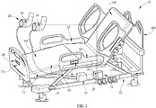
- FIG. 1 A person support apparatus 10 according to one illustrative embodiment of the current disclosure is shown in FIG. 1 .
- the person support apparatus 10 is a hospital bed.
- the person support apparatus 10 includes a lower frame or base 12, a plurality of supports 16 coupled with the lower frame 12, and an upper frame 14 supported by the plurality of supports above the lower frame 12.
- the upper frame 14 is configured to variably elevate with respect to the lower frame 12.
- a person support surface 18 is mounted on at least a portion of the person support apparatus 10.
- the person support surface 18 has a head support section HP, a seat support section SP and a foot support section FP as shown in FIG. 1 .
- the person support apparatus 10 may be a stretcher or an operating table in another embodiment as described in FIG 2 .
- FIG.1 illustrates a system to track usage of a compression sleeve comprising a fluid supply 22 mounted on the person support apparatus 10 and fluidly connected to the compression sleeve 20 using any one of a multitude of connection mechanisms, including quick disconnect type connectors.
- Compression sleeve 20 may be of any form, including but not limited to cuffs, boots and / or a wrap and may be customized to fit any body part.
- the fluid supply 22 is removably mounted on the foot board FB, head board HB or the side rails SR.
- the fluid supply 22 may be mounted on the compression sleeve 22.
- the fluid supply 22 may be used for other functions of the person support apparatus 10, including but not limited to inflation and / or deflation of a mattress.
- the system to track usage of a compression sleeve 20 comprises a dedicated fluid supply 22.
- the fluid supply 22 provides fluid to the compression sleeve 20 during inflation and vents the fluid from the compression sleeve 20 during deflation of the compression sleeve 20 in one embodiment.
- the fluid supply unit may be pneumatic or hydraulic in nature and may comprise a pump, blower, fan and/ or a compressor. Therefore, the compression sleeve may be inflated with air, water, oil or any other fluid.
- a controller 24 comprises a processor 26 in communication with the fluid supply 22 and provides a control signal to the fluid supply 22 to inflate or deflate the compression sleeve 20.
- the processor 26 also communicates with a pressure sensor 34 mounted on the compression sleeve 20 to allow measurement of the pressure inside the inflated compression sleeve 20 and / or the pressure applied on a patient's extremity to which the compression sleeve 20 is mounted.
- back pressure and / or electrical characteristics such as current and voltage changes of the prime mover of the fluid supply 22 may be used to determine the pressure in the compression sleeve in another embodiment.
- An electrical stimulation device 36 is mounted in the compression sleeve 20 to provide appropriate therapy to the patient.
- the electrical stimulation device 36 may be of any type, including a Transcutaneous Nerve Stimulation (TENS) type for blocking pain and / or an Electro Muscle Stimulation (EMS) device for stimulating muscles.
- the electrical stimulation device 36 is in communication with and receives control signals from the processor 26 to initiate or terminate therapy.
- the electrical stimulation device 36 receives power from the controller 24 while in another embodiment the electrical stimulation device 36 has a dedicated power source such as a battery pack.
- the controller 24 is in communication with a Graphical User Interface (GUI) 48 to display alarms and other messages.
- GUI 48 is integral to the person support apparatus 10 in one embodiment and is used to control other functions of the person support apparatus 10.
- the GUI 48 also allows for user inputs and commands to set thresholds for the amplitude, frequency and / or time duration of SCT and / or electrical stimulation therapy. These thresholds may be in the form of an upper bound (should not exceed), lower bound (should be greater than) and / or a range.
- the processor 26 uses these thresholds to determine compliance with prescribed therapy.
- the duration of cumulative therapy is tracked by the processor 26, by storing, in a memory device 28, data related to inflation and deflation of the compression sleeve 20 and / or operation of the electrical stimulation device.
- the memory device 28 may be of any type, including volatile and non-volatile types. If the cumulative duration of therapy does not meet the criteria established earlier, an alarm will be displayed on the GUI 48.
- GUI 48 Display of other performance characteristics of the therapy on the GUI 48 is well within the scope of this disclosure, including, but not limited to cumulative duration of therapy, duration of therapy of current session, average amplitude of therapy which in one embodiment may be the pressure and / or the electrical stimulation applied and frequency of therapy.
- the GUI 48 also allows a user to clear previously stored data in the memory device 28 and / or initiate therapy.
- the system to track usage of a compression sleeve includes a dedicated GUI 48, which may be in the form of a pendant.
- FIG.2 shows a compression sleeve 20 mounted in a stirrup 30 used in conjunction with an operating table.
- the processor 26 and the memory device 28 are mounted on the compression sleeve 20.
- the compression sleeve 20 is configured to couple to a fluid supply 22 mounted on the operating table using any type of connection mechanism, including a quick disconnect mechanism.
- the fluid supply 22 may be mounted on the stirrup 30 or the compression sleeve 22.
- the processor 26 and / or the memory device 28 wirelessly communicate with a communication network 40 ( FIG.3 ).
- the communication network 40 is in turn connected to a GUI 48, not shown in FIG.
- the illustrative embodiment as shown in FIG. 2 also describes a physiological sensor 32 mounted on the compression sleeve 22 in communication with the processor 26. It is well within the scope of the disclosure to include more than one physiological sensor 32 in the system. Physiological sensor 32 may be of any type and communicates with the processor 26 by way of an electrical signal indicative of at least one physiological parameter, including but not limited to temperature, blood pressure, heart rate and electrical activity. Processor 26 monitors the signals from the physiological sensor 32 and is configured to communicate an alarm to the GUI 48 in response to any of the physiological parameters not complying with a predetermined rule or threshold.
- the GUI is also configured to display data obtained from physiological sensors 32 via processor 26.
- the illustrative embodiment as described in FIG.2 allows for the same compression sleeve to be used in post-operative care as was used during an operation. This transfer from an operating room to post-operative care often involves changing rooms and / or person support apparatus 10. Since the system as described in FIG. 2 allows for mounting the processor 26 and memory device 28 on the compression sleeve 22, a continuous stream of data is available and a cumulative usage of the compression sleeve may be determined.
- the processor 26 and / or memory device 28 are configured to communicate with other controllers comprising processors and / or GUIs which in one embodiment may be remote.
- the processor 26 and / or the memory device 28 may communicate with a controller comprising a processor and / or GUI 48 integral to a patient support apparatus 10 via a wireless or wired connection based on the physical distance between the two devices.
- a controller comprising a processor and / or GUI 48 integral to a patient support apparatus 10 via a wireless or wired connection based on the physical distance between the two devices.
- the processor 26 and / or the memory device 28 automatically connects with the controller of the person support apparatus 10 in the post-operative room.
- a fluid supply 22 mounted on the compression sleeve 20 allows for continued therapy during patient transfer.
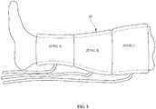
- FIG. 3 shows one embodiment of a compression sleeve 20 for use in the system to track usage of a compression sleeve.
- FIG. 3 shows the compression sleeve 20 used for sequential compression therapy of the patient's calf region.
- the compression sleeve 20 has more than one zone in this embodiment, although a single pressurized zone is well within the scope of the current disclosure.
- the sleeve as described in FIG. 3 has fluid supply lines connected to each zone, although a single supply line all the zones may be used in another embodiment.
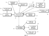
- FIG. 4 shows a block diagram of one embodiment of the system to track usage of a compression sleeve.
- the compression sleeve 20 is supplied fluid by a fluid supply 22, which in turn receives a control signal from the processor 26.
- At least one pressure sensor 34 mounted in the compression sleeve is in electrical communication with the processor 26.
- At least one electrical stimulation device 36 is also in communication with the processor 26.
- the processor 26 communicates with a memory device 28 and records parameters related to the sequential compression therapy, including, but not limited to any one or combination of the cumulative duration of therapy, duration of therapy for an individual session, amplitude and frequency of pressure applied.
- the processor 26 also conveys data corresponding to the signals received from at least one physiological sensor 32 and the electrical stimulation device 36 to the memory device 28.
- the processor 26 is also in communication with an alarm 38, which may be any combination of an audio, visual or tactile output.
- the processor 26 is configured to enable the alarm 38 based on the thresholds for sequential compression therapy, signals from the electrical stimulation device 36 or the physiological sensor 32.
- the processor 26 is in communication with a graphical user interface (GUI) 48 which allows for input of control parameters by a user and for display of system messages.
- GUI graphical user interface
- Alarm 38 may be triggered and in another embodiment a timer may be activated for the alarm to trigger after a predetermined time period.
- the memory device 28 is connected to a communication network 40.
- the communication network 40 may be of any type, including but not limited to Wide Area Network (WAN), Local Area Network (LAN), Virtual Private Network (VPN), telephone lines, optical communications, internet communications or telex.
- the communication network 40 is in communication with at least one Electronic Medical Record (EMR) 44 or another healthcare information database, a hospital communication station 42 and a nurse call system 46.
- EMR Electronic Medical Record
- the communication station 42 is a centralized location wherein one or more patients may be monitored by a caregiver. In one embodiment the communication station 42 may be stationary, while in another embodiment, it may be a mobile unit to accommodate prompt deployment.
- the processor 26 is connected to a communication network 40.
- the communication network 40 may be of any type, including but not limited to Wide Area Network (WAN), Local Area Network (LAN), Virtual Private Network (VPN), telephone lines, optical communications, internet communications or telex.
- the communication network 40 is in communication with at least one Electronic Medical Record (EMR) 44 or another healthcare information database, a hospital communication station 42 and a nurse call system 46.
- EMR Electronic Medical Record
- the communication station 42 is a centralized location wherein one or more patients may be monitored by a caregiver. In one embodiment the communication station 42 may be stationary, while in another embodiment, it may be a mobile unit to accommodate prompt deployment.
Abstract
Description
- Sequential compression therapy (SCT) is often used for prevention of deep venous thrombosis (DVT). Traditionally monitoring compliance and the utilization of sequential compression therapy by a patient are accomplished by a caregiver. While various systems have been developed for monitoring sequential compression therapy, there is still room for improvement. Thus, a need persists for further contribution in this area of technology.
- The present disclosure includes one or more of the features recited in the appended claims and/or the following features which, alone or in any combination, may comprise patentable subject matter.
- One embodiment of the system to track usage of a compression sleeve comprises a compression sleeve, a fluid supply operable to inflate the compression sleeve, a processor configured to control the operation of the fluid supply and a memory device configured to record duration of the inflation of the compression sleeve.
- Another embodiment of the system to monitor compliance of a compression sleeve usage comprises a memory device configured to record usage of a compression sleeve, a processor configured to compare the usage with a predetermined threshold.
- One embodiment of the method to monitor compliance of a compression sleeve usage comprises determining usage of a compression sleeve, comparing usage of a compression sleeve with a predetermined threshold and determining compliance by comparing usage of a compression sleeve with the predetermined threshold.
- Another embodiment of a system to monitor compliance of a compression sleeve usage comprises a compression sleeve and a first processor mounted on the compression sleeve configured to determine duration of inflation of the compression sleeve and communicate with a second processor mounted on a person support apparatus.
- The accompanying drawings incorporated in and forming a part of the specification illustrate several aspects of the claimed subject matter and, together with the description, serve to explain the principles of the claimed subject matter. In the drawings:
-
FIG. 1 is a perspective view of a system to track usage of a compression sleeve integrated with a hospital bed, constructed according to principles of one or more of the teachings herein; -
FIG. 2 is a perspective view of a system to track usage of a compression sleeve integrated with a fracture table, constructed according to principles of one or more of the teachings herein; -
FIG. 3 is a side view of a compression sleeve mounted on a patient's leg, constructed according to principles of one or more of the teachings herein; -
FIG. 4 is a block diagram of a system to monitor compliance of a compression sleeve, integrated with a hospital bed, constructed according to principles of one or more of the teachings herein; -
FIG. 5 is a block diagram of another system to monitor compliance of a compression sleeve, integrated with a hospital bed, constructed according to principles of one or more of the teachings herein; - The embodiments of the claimed subject mater and the various features and advantageous details thereof are explained more fully with reference to the non-limiting embodiments and examples that are described and/or illustrated in the accompanying drawings and detailed in the following description. It should be noted that the features illustrated in the drawings are not necessarily drawn to scale, and features of one embodiment may be employed with other embodiments as the skilled artisan would recognize, even if not explicitly stated herein. Descriptions of well-known components and processing techniques may be briefly mentioned or omitted so as to not unnecessarily obscure the embodiments of the claimed subject matter described. The examples used herein are intended merely to facilitate an understanding of ways in which the claimed subject matter may be practiced and to further enable those of skill in the art to practice the embodiments of the claimed subject matter described herein. Accordingly, the examples and embodiments herein are merely illustrative and should not be construed as limiting the scope of the claimed subject matter, which is defined solely by the appended claims and applicable law. Moreover, it is noted that like reference numerals represent similar parts throughout the several views of the drawings.
- It is understood that the subject matter claimed is not limited to the particular methodology, protocols, devices, apparatus, materials, applications, etc., described herein, as these may vary. It is also to be understood that the terminology used herein is used for the purpose of describing particular embodiments only, and is not intended to limit the scope of the claimed subject matter.
- Unless defined otherwise, all technical and scientific terms used herein have the same meanings as commonly understood by one of ordinary skill in the art.
- A person support
apparatus 10 according to one illustrative embodiment of the current disclosure is shown inFIG. 1 . In the illustrative embodiment as described inFIG. 1 , the person supportapparatus 10 is a hospital bed. Theperson support apparatus 10 includes a lower frame orbase 12, a plurality ofsupports 16 coupled with thelower frame 12, and anupper frame 14 supported by the plurality of supports above thelower frame 12. Theupper frame 14 is configured to variably elevate with respect to thelower frame 12. Aperson support surface 18 is mounted on at least a portion of the person supportapparatus 10. The person supportsurface 18 has a head support section HP, a seat support section SP and a foot support section FP as shown inFIG. 1 . The person supportapparatus 10 may be a stretcher or an operating table in another embodiment as described inFIG 2 .FIG.1 illustrates a system to track usage of a compression sleeve comprising afluid supply 22 mounted on theperson support apparatus 10 and fluidly connected to thecompression sleeve 20 using any one of a multitude of connection mechanisms, including quick disconnect type connectors.Compression sleeve 20 may be of any form, including but not limited to cuffs, boots and / or a wrap and may be customized to fit any body part. In one embodiment, thefluid supply 22 is removably mounted on the foot board FB, head board HB or the side rails SR. In another embodiment, thefluid supply 22 may be mounted on thecompression sleeve 22. Thefluid supply 22 may be used for other functions of the person supportapparatus 10, including but not limited to inflation and / or deflation of a mattress. In another embodiment, the system to track usage of acompression sleeve 20 comprises adedicated fluid supply 22. Thefluid supply 22 provides fluid to thecompression sleeve 20 during inflation and vents the fluid from thecompression sleeve 20 during deflation of thecompression sleeve 20 in one embodiment. The fluid supply unit may be pneumatic or hydraulic in nature and may comprise a pump, blower, fan and/ or a compressor. Therefore, the compression sleeve may be inflated with air, water, oil or any other fluid. Acontroller 24 comprises aprocessor 26 in communication with thefluid supply 22 and provides a control signal to thefluid supply 22 to inflate or deflate thecompression sleeve 20. Theprocessor 26 also communicates with apressure sensor 34 mounted on thecompression sleeve 20 to allow measurement of the pressure inside the inflatedcompression sleeve 20 and / or the pressure applied on a patient's extremity to which thecompression sleeve 20 is mounted. Alternatively, back pressure and / or electrical characteristics such as current and voltage changes of the prime mover of thefluid supply 22 may be used to determine the pressure in the compression sleeve in another embodiment. Anelectrical stimulation device 36 is mounted in thecompression sleeve 20 to provide appropriate therapy to the patient. Theelectrical stimulation device 36 may be of any type, including a Transcutaneous Nerve Stimulation (TENS) type for blocking pain and / or an Electro Muscle Stimulation (EMS) device for stimulating muscles. Theelectrical stimulation device 36 is in communication with and receives control signals from theprocessor 26 to initiate or terminate therapy. In one embodiment, theelectrical stimulation device 36 receives power from thecontroller 24 while in another embodiment theelectrical stimulation device 36 has a dedicated power source such as a battery pack. Thecontroller 24 is in communication with a Graphical User Interface (GUI) 48 to display alarms and other messages. TheGUI 48 is integral to the person supportapparatus 10 in one embodiment and is used to control other functions of the person supportapparatus 10. TheGUI 48 also allows for user inputs and commands to set thresholds for the amplitude, frequency and / or time duration of SCT and / or electrical stimulation therapy. These thresholds may be in the form of an upper bound (should not exceed), lower bound (should be greater than) and / or a range. Theprocessor 26 uses these thresholds to determine compliance with prescribed therapy. In one embodiment, the duration of cumulative therapy is tracked by theprocessor 26, by storing, in amemory device 28, data related to inflation and deflation of thecompression sleeve 20 and / or operation of the electrical stimulation device. Thememory device 28 may be of any type, including volatile and non-volatile types. If the cumulative duration of therapy does not meet the criteria established earlier, an alarm will be displayed on theGUI 48. Display of other performance characteristics of the therapy on theGUI 48 is well within the scope of this disclosure, including, but not limited to cumulative duration of therapy, duration of therapy of current session, average amplitude of therapy which in one embodiment may be the pressure and / or the electrical stimulation applied and frequency of therapy. TheGUI 48 also allows a user to clear previously stored data in thememory device 28 and / or initiate therapy. In another embodiment, the system to track usage of a compression sleeve includes adedicated GUI 48, which may be in the form of a pendant. - The illustrative embodiment as described in
FIG.2 shows acompression sleeve 20 mounted in astirrup 30 used in conjunction with an operating table. In the embodiment described inFIG. 2 , theprocessor 26 and thememory device 28 are mounted on thecompression sleeve 20. Thecompression sleeve 20 is configured to couple to afluid supply 22 mounted on the operating table using any type of connection mechanism, including a quick disconnect mechanism. In another embodiment, thefluid supply 22 may be mounted on thestirrup 30 or thecompression sleeve 22. Theprocessor 26 and / or thememory device 28 wirelessly communicate with a communication network 40 (FIG.3 ). Thecommunication network 40 is in turn connected to aGUI 48, not shown inFIG. 2 and theGUI 48 allows for inputting commands, display of messages and / or for communicating alarms received from theprocessor 26 and / or thememory device 28. The illustrative embodiment as shown inFIG. 2 also describes aphysiological sensor 32 mounted on thecompression sleeve 22 in communication with theprocessor 26. It is well within the scope of the disclosure to include more than onephysiological sensor 32 in the system.Physiological sensor 32 may be of any type and communicates with theprocessor 26 by way of an electrical signal indicative of at least one physiological parameter, including but not limited to temperature, blood pressure, heart rate and electrical activity.Processor 26 monitors the signals from thephysiological sensor 32 and is configured to communicate an alarm to theGUI 48 in response to any of the physiological parameters not complying with a predetermined rule or threshold. The GUI is also configured to display data obtained fromphysiological sensors 32 viaprocessor 26. The illustrative embodiment as described inFIG.2 allows for the same compression sleeve to be used in post-operative care as was used during an operation. This transfer from an operating room to post-operative care often involves changing rooms and / orperson support apparatus 10. Since the system as described inFIG. 2 allows for mounting theprocessor 26 andmemory device 28 on thecompression sleeve 22, a continuous stream of data is available and a cumulative usage of the compression sleeve may be determined. Theprocessor 26 and / ormemory device 28 are configured to communicate with other controllers comprising processors and / or GUIs which in one embodiment may be remote. Theprocessor 26 and / or thememory device 28 may communicate with a controller comprising a processor and / orGUI 48 integral to apatient support apparatus 10 via a wireless or wired connection based on the physical distance between the two devices. Thus, as the patient is moved from the operating room to a post-operative room, theprocessor 26 and / or thememory device 28 automatically connects with the controller of theperson support apparatus 10 in the post-operative room. As described earlier, afluid supply 22 mounted on thecompression sleeve 20 allows for continued therapy during patient transfer. - The illustrative embodiment as described in
FIG. 3 shows one embodiment of acompression sleeve 20 for use in the system to track usage of a compression sleeve.FIG. 3 shows thecompression sleeve 20 used for sequential compression therapy of the patient's calf region. As shown inFIG. 3 , thecompression sleeve 20 has more than one zone in this embodiment, although a single pressurized zone is well within the scope of the current disclosure. The sleeve as described inFIG. 3 has fluid supply lines connected to each zone, although a single supply line all the zones may be used in another embodiment. -
FIG. 4 shows a block diagram of one embodiment of the system to track usage of a compression sleeve. Thecompression sleeve 20 is supplied fluid by afluid supply 22, which in turn receives a control signal from theprocessor 26. At least onepressure sensor 34 mounted in the compression sleeve is in electrical communication with theprocessor 26. At least oneelectrical stimulation device 36 is also in communication with theprocessor 26. Theprocessor 26 communicates with amemory device 28 and records parameters related to the sequential compression therapy, including, but not limited to any one or combination of the cumulative duration of therapy, duration of therapy for an individual session, amplitude and frequency of pressure applied. Theprocessor 26 also conveys data corresponding to the signals received from at least onephysiological sensor 32 and theelectrical stimulation device 36 to thememory device 28. Theprocessor 26 is also in communication with analarm 38, which may be any combination of an audio, visual or tactile output. Theprocessor 26 is configured to enable thealarm 38 based on the thresholds for sequential compression therapy, signals from theelectrical stimulation device 36 or thephysiological sensor 32. Theprocessor 26 is in communication with a graphical user interface (GUI) 48 which allows for input of control parameters by a user and for display of system messages.Alarm 38 may be triggered and in another embodiment a timer may be activated for the alarm to trigger after a predetermined time period. - In the illustrative embodiment shown in
FIG. 4 , thememory device 28 is connected to acommunication network 40. Thecommunication network 40 may be of any type, including but not limited to Wide Area Network (WAN), Local Area Network (LAN), Virtual Private Network (VPN), telephone lines, optical communications, internet communications or telex. Thecommunication network 40 is in communication with at least one Electronic Medical Record (EMR) 44 or another healthcare information database, ahospital communication station 42 and anurse call system 46. Thecommunication station 42 is a centralized location wherein one or more patients may be monitored by a caregiver. In one embodiment thecommunication station 42 may be stationary, while in another embodiment, it may be a mobile unit to accommodate prompt deployment. In the illustrative embodiment shown inFIG. 5 , theprocessor 26 is connected to acommunication network 40. Thecommunication network 40 may be of any type, including but not limited to Wide Area Network (WAN), Local Area Network (LAN), Virtual Private Network (VPN), telephone lines, optical communications, internet communications or telex. Thecommunication network 40 is in communication with at least one Electronic Medical Record (EMR) 44 or another healthcare information database, ahospital communication station 42 and anurse call system 46. Thecommunication station 42 is a centralized location wherein one or more patients may be monitored by a caregiver. In one embodiment thecommunication station 42 may be stationary, while in another embodiment, it may be a mobile unit to accommodate prompt deployment. - The use of the terms "a" and "an" and "the" and similar referents in the context of describing the subject matter (particularly in the context of the following claims) are to be construed to cover both the singular and the plural, unless otherwise indicated herein or clearly contradicted by context. Recitation of ranges of values herein are merely intended to serve as a shorthand method of referring individually to each separate value falling within the range, unless otherwise indicated herein, and each separate value is incorporated into the specification as if it were individually recited herein. Furthermore, the foregoing description is for the purpose of illustration only, and not for the purpose of limitation, as the scope of protection sought is defined by the claims as set forth hereinafter together with any equivalents thereof entitled to. The use of any and all examples, or exemplary language (e.g., "such as") provided herein, is intended merely to better illustrate the subject matter and does not pose a limitation on the scope of the subject matter unless otherwise claimed. The use of the term "based on" and other like phrases indicating a condition for bringing about a result, both in the claims and in the written description, is not intended to foreclose any other conditions that bring about that result. No language in the specification should be construed as indicating any non-claimed element as essential to the practice of the invention as claimed.
- Preferred embodiments are described herein, including the best mode known to the inventor for carrying out the claimed subject matter. Of course, variations of those preferred embodiments will become apparent to those of ordinary skill in the art upon reading the foregoing description. The inventor expects skilled artisans to employ such variations as appropriate, and the inventor intends for the claimed subject matter to be practiced otherwise than as specifically described herein. Accordingly, this claimed subject matter includes all modifications and equivalents of the subject matter recited in the claims appended hereto as permitted by applicable law. Moreover, any combination of the above-described elements in all possible variations thereof is encompassed unless otherwise indicated herein or otherwise clearly contradicted by context.
- The disclosures of any references and publications cited above are expressly incorporated by reference in their entireties to the same extent as if each were incorporated by reference individually
- Further features of the present disclosure are provided in the following list of numbered clauses, and dependent clauses:
- Clause 1. A system to track usage of a compression sleeve comprising:
- a fluid supply operable to inflate said compression sleeve;
- a processor coupled to a person support apparatus, said processor is configured to control operation of said fluid supply; and
- a memory device configured to record duration of said inflation of said compression sleeve.
- Clause 2. The system of clause 1 wherein said memory device is configured to communicate data with a communication network.
- Clause 3. The system of clause 2 wherein said communication network is configured to communicate with an electronic medical record.
- Clause 4. The system of clause 2 or 3 wherein said communication network is configured to communicate with a nurse call system.
- Clause 5. The system of clause 2, 3 or 4 wherein said communication network is configured to communicate with a hospital station.
- Clause 6. The system of any of the preceding clauses, wherein said memory device is coupled to said compression sleeve.
- Clause 7. The system of any of the preceding clauses, comprising a pressure sensor is configured to communicate pressure in said compression sleeve to said processor.
- Clause 8. The system of any of the preceding clauses, said processor is configured to compare said usage of said compression sleeve with a predetermined threshold.
- Clause 9. The system of any of the preceding clauses, further comprising at least one physiological sensor coupled to said compression sleeve is configured to communicate at least one physiological signal to said processor.
-
Clause 10. The system of clause 9, further comprising an alarm in communication with said processor, said processor is configured to trigger said alarm if at least one physiological signal is outside a predetermined range. - Clause 11. The system of
claim 9 or 10, further comprising an electrical stimulation device operably connected to said processor. -
Clause 12. The system of any of the preceding clauses, wherein said memory device is configured to record the frequency of compressive therapy provided by said compression sleeve. - Clause 13. The system of any of the preceding clauses, wherein said memory device is configured to record the amplitude of compression applied by said compression sleeve.
Clause 14. The system of any of the preceding clauses, wherein said memory device is configured to record the duration of application of compressive therapy by said compression sleeve. - Clause 15. The system of any of the preceding clauses, wherein said fluid supply is mounted on said person support apparatus.
-
Clause 16. The system of any of the preceding clauses, wherein said processor is configured to control at least one function of said person support apparatus. - Clause 17. The system of any of any of the preceding clauses, further comprising a display unit mounted on said person support apparatus, wherein said display unit is configured to display said duration of inflation of said compression sleeve.
-
Clause 18. A system to monitor compliance of a compression sleeve usage comprising:- a memory device configured to record usage of a compression sleeve;
- a processor configured to compare said usage with a predetermined threshold, said processor is configured to communicate with a controller of a person support apparatus. Clause 19. The system of
clause 18, further comprising a communication network in communication with said processor, said processor is configured to communicate said usage of said compression sleeve by way of said communication network.
-
Clause 20. The system ofclause 18 or 19, further comprising at least one physiological sensor is configured to measure at least one physiological signal and communicate said physiological signal to said processor. - Clause 21. The system of
clause -
Clause 22. The system of any ofclauses 18 to 21, wherein said processor is configured to determine said usage based up on amplitude of compression applied by said compression sleeve. - Clause 23. The system of any of
clauses 18 to 22, wherein said processor is configured to determine said usage based up on duration of application of compressive therapy by said compression sleeve. -
Clause 24. The system of any ofclauses 18 to 23, further comprising a display unit mounted on said person support apparatus, said display unit in communication with said processor and is configured to display said usage of said compression sleeve. - Clause 25. A method to monitor compliance of a compression sleeve usage comprising:
- determining usage of a compression sleeve;
- comparing usage of a compression sleeve with a predetermined threshold;
- determining compliance by comparing usage of a compression sleeve with said predetermined threshold.
-
Clause 26. The method of clause 25, further comprising the step of monitoring at least one physiological signal from a sensor. - Clause 27. The method of
clause 25 or 26, further comprising the step of communicating the usage of said compression sleeve to a healthcare database. -
Clause 28. The method ofclause 25, 26 or 27, further comprising the step of triggering an alarm if the usage of said compression sleeve is below said predetermined threshold. - Clause 29. The method of any of clauses 25 to 28, further comprising the step of communicating with a processor mounted on a person support apparatus.
-
Clause 30. A system to monitor compliance of a compression sleeve usage comprising:- a compression sleeve;
- a first processor mounted on said compression sleeve is configured to determine duration of inflation of said compression sleeve and communicate with a second processor mounted on a person support apparatus.
Claims (12)
- A person support apparatus (10) for use with a compression sleeve (20), comprising:a person support surface;a controller (24) comprising a processor (26) and memory device (28);a GUI (48) integral to the person support apparatus; andat least one physiological sensor (32) configured to measure at least one physiological signal and communicate said physiological signal to said processor (26);wherein:the controller (24) and GUI (49) are configured to receive user inputs and commands, and control at least one function of said person support apparatus;the memory device (28) is configured to record usage of the compression sleeve (20), the usage determined by the processor (26);the memory device (28), or processor (26), is connected to a communication network (40) in communication with at least one of an Electronic Medical Record (44), a nurse call system (46), and a hospital station (42); andthe memory device (28), or processor (26), is configured to communicate, via the communication network (40), signals received from the or each physiological sensor (32) and the recorded usage of the compression sleeve (20) to at least one of the Electronic Medical Record (44), nurse call system (46), and hospital station (42).
- The person support apparatus according to Claim 1, wherein the processor is configured to determine usage of the compression sleeve (20) for an individual session based on at least one of duration of application of compressive therapy by said compression sleeve (20), amplitude of compression applied by said compression sleeve (20) and frequency of compressive therapy provided by said compression sleeve (20).
- The person support apparatus according to Claim 1 or 2, further comprising an alarm in communication with said processor (26), the processor (26) configured to trigger the alarm if at least one physiological signal is outside a predetermined range.
- The person support apparatus according to Claim 3, the processor (26) being configured to trigger the alarm if the usage of said compression sleeve (20) is below a predetermined threshold.
- The person support apparatus according to any of Claims 1 to 4, further comprising a fluid supply (22) operable to inflate the compression sleeve (20).
- The person support apparatus according to Claim 5, further comprising a compression sleeve (20) coupled to the fluid supply (22).
- The person support apparatus according to Claim 5 or 6, wherein the processor (26) is in communication with the fluid supply (22) and is configured to provide a control signal to the fluid supply (22) to inflate or deflate the compression sleeve (20).
- The person support apparatus according to Claim 7, wherein the processor (26) is configured to communicate with a pressure sensor (34) mounted on the compression sleeve (20) to allow measurement of the pressure inside the inflated compression sleeve (20).
- The person support apparatus according to Claim 8, wherein the memory device (28) is configured to record parameters related to the use of the compression sleeve (20) for sequential compression therapy.
- The person support apparatus according to any of claims 6 to 8, wherein the compression sleeve (20) comprises an electrical stimulation device (36) mounted thereto, the memory device configured to record usage of the electrical stimulation device (36).
- The person support apparatus according to any of the preceding claims, wherein the GUI is configured to display the signals received by the processor (26) from the or each physiological sensor (32) and the recorded usage of the compression sleeve (20).
- The person support apparatus according to any of the preceding claims, wherein the at least one physiological sensor is configured to output an electrical signal indicative of at least one of the physiological parameters: temperature; blood pressure; heart rate; and electrical activity.
Applications Claiming Priority (3)
| Application Number | Priority Date | Filing Date | Title |
|---|---|---|---|
| US13/410,502 US20130231596A1 (en) | 2012-03-02 | 2012-03-02 | Sequential compression therapy compliance monitoring systems & methods |
| PCT/US2013/028629 WO2013130980A1 (en) | 2012-03-02 | 2013-03-01 | Sequential compression therapy compliance monitoring systems and methods |
| EP20130755188 EP2819630A4 (en) | 2012-03-02 | 2013-03-01 | Sequential compression therapy compliance monitoring systems and methods |
Related Parent Applications (1)
| Application Number | Title | Priority Date | Filing Date |
|---|---|---|---|
| EP20130755188 Division EP2819630A4 (en) | 2012-03-02 | 2013-03-01 | Sequential compression therapy compliance monitoring systems and methods |
Publications (1)
| Publication Number | Publication Date |
|---|---|
| EP3352173A1 true EP3352173A1 (en) | 2018-07-25 |
Family
ID=49043229
Family Applications (2)
| Application Number | Title | Priority Date | Filing Date |
|---|---|---|---|
| EP20130755188 Withdrawn EP2819630A4 (en) | 2012-03-02 | 2013-03-01 | Sequential compression therapy compliance monitoring systems and methods |
| EP17209100.1A Withdrawn EP3352173A1 (en) | 2012-03-02 | 2013-03-01 | Sequential compression therapy compliance monitoring systems and methods |
Family Applications Before (1)
| Application Number | Title | Priority Date | Filing Date |
|---|---|---|---|
| EP20130755188 Withdrawn EP2819630A4 (en) | 2012-03-02 | 2013-03-01 | Sequential compression therapy compliance monitoring systems and methods |
Country Status (3)
| Country | Link |
|---|---|
| US (1) | US20130231596A1 (en) |
| EP (2) | EP2819630A4 (en) |
| WO (1) | WO2013130980A1 (en) |
Families Citing this family (38)
| Publication number | Priority date | Publication date | Assignee | Title |
|---|---|---|---|---|
| US9642759B2 (en) | 2007-04-13 | 2017-05-09 | Stryker Corporation | Patient support with universal energy supply system |
| US20120083712A1 (en) | 2010-09-30 | 2012-04-05 | Tyco Healthcare Group Lp | Monitoring Compliance Using Venous Refill Detection |
| AU2011316599B2 (en) | 2010-10-12 | 2018-09-20 | Smith & Nephew, Inc. | Medical device |
| US9737454B2 (en) | 2012-03-02 | 2017-08-22 | Hill-Rom Services, Inc. | Sequential compression therapy compliance monitoring systems and methods |
| CN105492035B (en) | 2013-03-14 | 2019-06-14 | 史密夫和内修有限公司 | System and method for application decompression treatment |
| US9737649B2 (en) | 2013-03-14 | 2017-08-22 | Smith & Nephew, Inc. | Systems and methods for applying reduced pressure therapy |
| US10322045B1 (en) * | 2013-05-29 | 2019-06-18 | Paul Cuneo | Footboard for hospital bed with therapeutic mechanisms housed within |
| WO2015023515A1 (en) | 2013-08-13 | 2015-02-19 | Smith & Nephew, Inc. | Systems and methods for applying reduced pressure therapy |
| US20150057585A1 (en) * | 2013-08-20 | 2015-02-26 | Covidien Lp | Compression device having compliance tracking |
| US10226211B2 (en) | 2014-10-11 | 2019-03-12 | Zimmer Dental, Ltd. | System and method for determining user's deep vein thrombosis prevention and diagnosis system utilization compliance |
| US10022291B2 (en) | 2014-12-04 | 2018-07-17 | The Sensory Chair Company, Inc. | Sensory furniture system for treatments, method of use, and method of manufacture |
| WO2017062042A1 (en) | 2015-10-07 | 2017-04-13 | Smith & Nephew, Inc. | Systems and methods for applying reduced pressure therapy |
| WO2017062959A1 (en) | 2015-10-09 | 2017-04-13 | Covidien Lp | Compression garment compliance |
| US10667984B2 (en) | 2015-12-18 | 2020-06-02 | Stryker Corporation | Systems and methods for operating patient therapy devices |
| US10507158B2 (en) | 2016-02-18 | 2019-12-17 | Hill-Rom Services, Inc. | Patient support apparatus having an integrated limb compression device |
| EP3454917B1 (en) | 2016-05-13 | 2022-04-06 | Smith & Nephew, Inc | Automatic wound coupling detection in negative pressure wound therapy systems |
| JP7063887B2 (en) | 2016-09-29 | 2022-05-09 | スミス アンド ネフュー インコーポレイテッド | Construction and protection of components in negative pressure wound healing systems |
| US11410771B2 (en) | 2017-06-01 | 2022-08-09 | Stryker Corporation | Patient care devices with open communication |
| US11712508B2 (en) | 2017-07-10 | 2023-08-01 | Smith & Nephew, Inc. | Systems and methods for directly interacting with communications module of wound therapy apparatus |
| US11123246B2 (en) * | 2017-12-22 | 2021-09-21 | Stryker Corporation | Techniques for managing patient therapy protocols |
| US11246775B2 (en) | 2017-12-28 | 2022-02-15 | Stryker Corporation | Patient turning device for a patient support apparatus |
| US11173085B2 (en) | 2017-12-28 | 2021-11-16 | Stryker Corporation | Mattress cover for a mattress providing rotation therapy to a patient |
| USD888964S1 (en) | 2018-09-28 | 2020-06-30 | Stryker Corporation | Crib assembly for a patient support |
| USD877915S1 (en) | 2018-09-28 | 2020-03-10 | Stryker Corporation | Crib assembly |
| USD888962S1 (en) | 2018-09-28 | 2020-06-30 | Stryker Corporation | Cover assembly for a patient support |
| USD901940S1 (en) | 2018-09-28 | 2020-11-17 | Stryker Corporation | Patient support |
| USD888963S1 (en) | 2018-09-28 | 2020-06-30 | Stryker Corporation | Cover assembly for a patient support |
| USD977109S1 (en) | 2018-09-28 | 2023-01-31 | Stryker Corporation | Crib assembly for a patient support |
| USD879966S1 (en) | 2018-09-28 | 2020-03-31 | Stryker Corporation | Crib assembly |
| USD894956S1 (en) | 2018-10-31 | 2020-09-01 | Stryker Corporation | Display screen or portion thereof with graphical user interface |
| US11559451B2 (en) | 2018-10-31 | 2023-01-24 | Stryker Corporation | Fluid source for supplying fluid to therapy devices |
| USD892159S1 (en) | 2018-10-31 | 2020-08-04 | Stryker Corporation | Display screen with animated graphical user interface |
| USD890914S1 (en) | 2018-10-31 | 2020-07-21 | Stryker Corporation | Pump |
| USD894226S1 (en) | 2018-10-31 | 2020-08-25 | Stryker Corporation | Display screen or portion thereof with graphical user interface |
| USD893543S1 (en) | 2018-10-31 | 2020-08-18 | Stryker Corporation | Display screen with graphical user interface |
| USD894957S1 (en) | 2018-10-31 | 2020-09-01 | Stryker Corporation | Display screen or portion thereof with graphical user interface |
| USD894223S1 (en) | 2018-10-31 | 2020-08-25 | Stryker Corporation | Display screen with animated graphical user interface |
| GB201820668D0 (en) | 2018-12-19 | 2019-01-30 | Smith & Nephew Inc | Systems and methods for delivering prescribed wound therapy |
Citations (4)
| Publication number | Priority date | Publication date | Assignee | Title |
|---|---|---|---|---|
| US5674262A (en) * | 1996-01-26 | 1997-10-07 | Kinetic Concepts, Inc. | Pneumatic compression and functional electric stimulation device and method using the same |
| WO2000000155A1 (en) * | 1996-04-29 | 2000-01-06 | Abatis Medical Technologies Limited | Apparatus and method for monitoring pneumatic limb compression therapy |
| US20070049853A1 (en) * | 2005-07-21 | 2007-03-01 | Bristol-Myers Squibb Company | Compression device for the limb |
| EP2272479A2 (en) * | 2009-07-10 | 2011-01-12 | Hill-Rom Services, Inc. | Systems for patient support, monitoring, and treatment |
Family Cites Families (54)
| Publication number | Priority date | Publication date | Assignee | Title |
|---|---|---|---|---|
| US4321929A (en) * | 1979-10-12 | 1982-03-30 | Lemelson Jerome H | Tourniquet |
| US6468237B1 (en) * | 1991-12-17 | 2002-10-22 | Kinetic Concepts, Inc. | Pneumatic pump, housing and methods for medical purposes |
| DE69232191T2 (en) * | 1991-12-17 | 2002-08-29 | Kinetic Concepts Inc | PNEUMATIC COMPRESSION DEVICE FOR USE IN THE MEDICAL AREA |
| US5490820A (en) * | 1993-03-12 | 1996-02-13 | Datascope Investment Corp. | Active compression/decompression cardiac assist/support device and method |
| US5443440A (en) * | 1993-06-11 | 1995-08-22 | Ndm Acquisition Corp. | Medical pumping apparatus |
| US8015033B2 (en) * | 1994-04-26 | 2011-09-06 | Health Hero Network, Inc. | Treatment regimen compliance and efficacy with feedback |
| AU5185496A (en) * | 1995-03-14 | 1996-10-02 | Vnus Medical Technologies, Inc. | Venous pump efficiency test system and method |
| US5771511A (en) * | 1995-08-04 | 1998-06-30 | Hill-Rom, Inc. | Communication network for a hospital bed |
| US5630238A (en) * | 1995-08-04 | 1997-05-20 | Hill-Rom, Inc. | Bed with a plurality of air therapy devices, having control modules and an electrical communication network |
| US5840049A (en) * | 1995-09-07 | 1998-11-24 | Kinetic Concepts, Inc. | Medical pumping apparatus |
| US6736787B1 (en) * | 1996-04-29 | 2004-05-18 | Mcewen James Allen | Apparatus for applying pressure waveforms to a limb |
| US6911916B1 (en) * | 1996-06-24 | 2005-06-28 | The Cleveland Clinic Foundation | Method and apparatus for accessing medical data over a network |
| US6387065B1 (en) * | 1996-09-30 | 2002-05-14 | Kinetic Concepts, Inc. | Remote controllable medical pumping apparatus |
| ATE346578T1 (en) * | 1997-08-18 | 2006-12-15 | Cpca2000 Inc | COUNTER PULSATION DEVICE USING UNCOMPRESSED AIR |
| DE69816645T2 (en) * | 1997-11-07 | 2004-04-15 | Hill-Rom Services, Inc., Batesville | THERMAL CONTROL SYSTEM FOR PATIENTS |
| US5968073A (en) * | 1997-11-17 | 1999-10-19 | Jacobs; Laura F. | Methods and apparatus for applying pressure |
| US6544202B2 (en) * | 1998-08-12 | 2003-04-08 | Mcewen James Allen | Apparatus and method for applying an adaptable pressure waveform to a limb |
| US8419650B2 (en) * | 1999-04-16 | 2013-04-16 | Cariocom, LLC | Downloadable datasets for a patient monitoring system |
| CA2394754A1 (en) * | 1999-12-29 | 2001-07-05 | Hill-Rom Services, Inc. | Hospital bed |
| US6730024B2 (en) * | 2000-05-17 | 2004-05-04 | Brava, Llc | Method and apparatus for collecting patient compliance data including processing and display thereof over a computer network |
| US6514200B1 (en) * | 2000-05-17 | 2003-02-04 | Brava, Llc | Patient compliance monitor |
| US6589267B1 (en) * | 2000-11-10 | 2003-07-08 | Vasomedical, Inc. | High efficiency external counterpulsation apparatus and method for controlling same |
| US6558338B1 (en) * | 2000-11-20 | 2003-05-06 | Mego Afek Industrial Measuring Instruments | System for and method of applying pressure to human body |
| US20020087054A1 (en) * | 2001-01-03 | 2002-07-04 | Wen-Guai Lin | System and a method for monitoring the effectiveness of a medical treatment |
| CA2439163A1 (en) * | 2001-03-30 | 2002-10-10 | Hill-Rom Services, Inc. | Hospital bed and network system |
| US6890285B2 (en) * | 2001-10-01 | 2005-05-10 | Tariq Rahman | Brace compliance monitor |
| US20040097844A1 (en) * | 2002-11-15 | 2004-05-20 | Advanced Respiratory, Inc. | Oscillatory chest wall compression device with improved air pulse generator with reduced size and weight |
| WO2004091463A2 (en) * | 2003-04-11 | 2004-10-28 | Hill-Rom Services, Inc. | System for compression therapy |
| US8125318B2 (en) * | 2004-09-10 | 2012-02-28 | Hill-Rom Services, Inc. | Wireless control system for a patient-support apparatus |
| US20060058716A1 (en) * | 2004-09-14 | 2006-03-16 | Hui John C K | Unitary external counterpulsation device |
| US7487562B2 (en) * | 2005-11-30 | 2009-02-10 | Hill-Rom Services, Inc. | Hospital bed having head angle alarm |
| US20070180616A1 (en) * | 2006-02-08 | 2007-08-09 | Hill-Rom Services, Inc. | User module for a patient support |
| KR20090031771A (en) * | 2006-07-12 | 2009-03-27 | 아비트론 인코포레이티드 | Methods and systems for compliance confirmation and incentives |
| US7945461B2 (en) * | 2007-02-15 | 2011-05-17 | Vivonex, L.L.C. | Prescription compliance monitoring system |
| US8572778B2 (en) * | 2007-03-30 | 2013-11-05 | Hill-Rom Services, Inc. | User interface for hospital bed |
| US8108957B2 (en) * | 2007-05-31 | 2012-02-07 | Hill-Rom Services, Inc. | Pulmonary mattress |
| US20090049610A1 (en) * | 2007-08-20 | 2009-02-26 | Hill-Rom Services, Inc. | Proximity activation of voice operation of hospital bed |
| US8579841B2 (en) * | 2007-10-09 | 2013-11-12 | Sitara R. Khan | Blood clot prevention device |
| US8082160B2 (en) * | 2007-10-26 | 2011-12-20 | Hill-Rom Services, Inc. | System and method for collection and communication of data from multiple patient care devices |
| US8584282B2 (en) * | 2008-11-21 | 2013-11-19 | Hill-Rom Services, Inc. | Boost feature for a bed |
| WO2010065590A2 (en) * | 2008-12-02 | 2010-06-10 | Eddy Patrick E | Device for measuring a body part of a living being |
| US8314781B2 (en) * | 2010-02-26 | 2012-11-20 | Hill-Rom Services, Inc. | Hospital bed having multiple touchscreen displays |
| US8650682B2 (en) * | 2010-03-02 | 2014-02-18 | Hill-Rom Services, Inc. | Multifunctional display for hospital bed |
| US8387179B2 (en) * | 2010-08-30 | 2013-03-05 | Hill-Rom Services, Inc. | Siderail mechanism |
| US8745785B2 (en) * | 2010-08-30 | 2014-06-10 | Hill-Rom Services, Inc. | Siderail mechanism |
| US20120083712A1 (en) * | 2010-09-30 | 2012-04-05 | Tyco Healthcare Group Lp | Monitoring Compliance Using Venous Refill Detection |
| US9492341B2 (en) * | 2010-10-08 | 2016-11-15 | Hill-Rom Services, Inc. | Hospital bed with graphical user interface having advanced functionality |
| US8745786B2 (en) * | 2010-11-10 | 2014-06-10 | Hill-Rom Services, Inc. | Siderail assembly for patient support apparatus |
| EP2484327A3 (en) * | 2011-02-08 | 2013-10-09 | Hill-Rom Services, Inc. | Occupant support with multi-modal contol |
| US20130014324A1 (en) * | 2011-07-12 | 2013-01-17 | Timothy Joseph Receveur | Health Care Delivery System and Components Thereof |
| US20130046216A1 (en) * | 2011-08-19 | 2013-02-21 | Christopher R. O'Keefe | System for deep vein thrombosis therapy integral to a person support apparatus |
| US8844820B2 (en) * | 2011-08-24 | 2014-09-30 | Hill-Rom Services, Inc. | Multi-directional optical reader for a patient support |
| US20130074268A1 (en) * | 2011-09-23 | 2013-03-28 | Timothy Joseph Receveur | Structural pneumatic accumulator system |
| US8973186B2 (en) * | 2011-12-08 | 2015-03-10 | Hill-Rom Services, Inc. | Optimization of the operation of a patient-support apparatus based on patient response |
-
2012
- 2012-03-02 US US13/410,502 patent/US20130231596A1/en not_active Abandoned
-
2013
- 2013-03-01 WO PCT/US2013/028629 patent/WO2013130980A1/en active Application Filing
- 2013-03-01 EP EP20130755188 patent/EP2819630A4/en not_active Withdrawn
- 2013-03-01 EP EP17209100.1A patent/EP3352173A1/en not_active Withdrawn
Patent Citations (4)
| Publication number | Priority date | Publication date | Assignee | Title |
|---|---|---|---|---|
| US5674262A (en) * | 1996-01-26 | 1997-10-07 | Kinetic Concepts, Inc. | Pneumatic compression and functional electric stimulation device and method using the same |
| WO2000000155A1 (en) * | 1996-04-29 | 2000-01-06 | Abatis Medical Technologies Limited | Apparatus and method for monitoring pneumatic limb compression therapy |
| US20070049853A1 (en) * | 2005-07-21 | 2007-03-01 | Bristol-Myers Squibb Company | Compression device for the limb |
| EP2272479A2 (en) * | 2009-07-10 | 2011-01-12 | Hill-Rom Services, Inc. | Systems for patient support, monitoring, and treatment |
Also Published As
| Publication number | Publication date |
|---|---|
| US20130231596A1 (en) | 2013-09-05 |
| EP2819630A4 (en) | 2015-05-13 |
| EP2819630A1 (en) | 2015-01-07 |
| WO2013130980A1 (en) | 2013-09-06 |
Similar Documents
| Publication | Publication Date | Title |
|---|---|---|
| EP3352173A1 (en) | Sequential compression therapy compliance monitoring systems and methods | |
| US10943678B2 (en) | Sequential compression therapy compliance monitoring systems and methods | |
| US20210353181A1 (en) | System, apparatus, and method for monitoring and promoting patient mobility | |
| US20180085261A1 (en) | Telemedical wearable sensing method for management of chronic venous disorders | |
| US9044367B2 (en) | Patient weighing and bed exit monitoring | |
| US11769590B2 (en) | Techniques for remotely controlling a medical device based on image data | |
| JP2017159049A (en) | Adverse event mitigation system, method and device | |
| EP2272479A3 (en) | Systems for patient support, monitoring, and treatment | |
| JP2015531261A (en) | Apparatus and method for improving the reliability of physiological parameter measurement | |
| WO2011159543A2 (en) | Pressure sensor for monitoring a subject and pressure sensor with inflatable bladder | |
| US20130046216A1 (en) | System for deep vein thrombosis therapy integral to a person support apparatus | |
| US20160001034A1 (en) | Device method and system for reducing anxiety in an individual | |
| EP2561802A2 (en) | Occupant support suite and method for responding to an acoustic signature of a stand alone device | |
| KR20170135336A (en) | Patient Management System and method for controlling the same | |
| US11712399B2 (en) | Chest compression machine systems and methods | |
| EP3714856B1 (en) | Patient support apparatus with integrated patient therapy device | |
| US20230036488A1 (en) | Controllers for managing pressure-mitigation devices and approaches to accomplishing the same using information obtained or derived from electronic health records | |
| WO2024086795A2 (en) | Controllers designed for multi-component use and approaches to using the same to inflate multiple pressure-mitigation apparatuses |
Legal Events
| Date | Code | Title | Description |
|---|---|---|---|
| PUAI | Public reference made under article 153(3) epc to a published international application that has entered the european phase |
Free format text: ORIGINAL CODE: 0009012 |
|
| STAA | Information on the status of an ep patent application or granted ep patent |
Free format text: STATUS: THE APPLICATION HAS BEEN PUBLISHED |
|
| AC | Divisional application: reference to earlier application |
Ref document number: 2819630 Country of ref document: EP Kind code of ref document: P |
|
| AK | Designated contracting states |
Kind code of ref document: A1 Designated state(s): AL AT BE BG CH CY CZ DE DK EE ES FI FR GB GR HR HU IE IS IT LI LT LU LV MC MK MT NL NO PL PT RO RS SE SI SK SM TR |
|
| STAA | Information on the status of an ep patent application or granted ep patent |
Free format text: STATUS: REQUEST FOR EXAMINATION WAS MADE |
|
| 17P | Request for examination filed |
Effective date: 20190125 |
|
| RBV | Designated contracting states (corrected) |
Designated state(s): AL AT BE BG CH CY CZ DE DK EE ES FI FR GB GR HR HU IE IS IT LI LT LU LV MC MK MT NL NO PL PT RO RS SE SI SK SM TR |
|
| STAA | Information on the status of an ep patent application or granted ep patent |
Free format text: STATUS: EXAMINATION IS IN PROGRESS |
|
| 17Q | First examination report despatched |
Effective date: 20200819 |
|
| STAA | Information on the status of an ep patent application or granted ep patent |
Free format text: STATUS: THE APPLICATION HAS BEEN WITHDRAWN |
|
| 18W | Application withdrawn |
Effective date: 20201127 |