EP3351903A1 - Travel route generation device and a method for operating a travel route generation device - Google Patents
Travel route generation device and a method for operating a travel route generation device Download PDFInfo
- Publication number
- EP3351903A1 EP3351903A1 EP17175342.9A EP17175342A EP3351903A1 EP 3351903 A1 EP3351903 A1 EP 3351903A1 EP 17175342 A EP17175342 A EP 17175342A EP 3351903 A1 EP3351903 A1 EP 3351903A1
- Authority
- EP
- European Patent Office
- Prior art keywords
- travel
- travel route
- route
- work
- unit
- Prior art date
- Legal status (The legal status is an assumption and is not a legal conclusion. Google has not performed a legal analysis and makes no representation as to the accuracy of the status listed.)
- Granted
Links
Images

Classifications
-
- G—PHYSICS
- G01—MEASURING; TESTING
- G01C—MEASURING DISTANCES, LEVELS OR BEARINGS; SURVEYING; NAVIGATION; GYROSCOPIC INSTRUMENTS; PHOTOGRAMMETRY OR VIDEOGRAMMETRY
- G01C21/00—Navigation; Navigational instruments not provided for in groups G01C1/00 - G01C19/00
- G01C21/20—Instruments for performing navigational calculations
-
- G—PHYSICS
- G01—MEASURING; TESTING
- G01C—MEASURING DISTANCES, LEVELS OR BEARINGS; SURVEYING; NAVIGATION; GYROSCOPIC INSTRUMENTS; PHOTOGRAMMETRY OR VIDEOGRAMMETRY
- G01C21/00—Navigation; Navigational instruments not provided for in groups G01C1/00 - G01C19/00
- G01C21/26—Navigation; Navigational instruments not provided for in groups G01C1/00 - G01C19/00 specially adapted for navigation in a road network
- G01C21/34—Route searching; Route guidance
- G01C21/3407—Route searching; Route guidance specially adapted for specific applications
-
- A—HUMAN NECESSITIES
- A01—AGRICULTURE; FORESTRY; ANIMAL HUSBANDRY; HUNTING; TRAPPING; FISHING
- A01B—SOIL WORKING IN AGRICULTURE OR FORESTRY; PARTS, DETAILS, OR ACCESSORIES OF AGRICULTURAL MACHINES OR IMPLEMENTS, IN GENERAL
- A01B69/00—Steering of agricultural machines or implements; Guiding agricultural machines or implements on a desired track
- A01B69/007—Steering or guiding of agricultural vehicles, e.g. steering of the tractor to keep the plough in the furrow
- A01B69/008—Steering or guiding of agricultural vehicles, e.g. steering of the tractor to keep the plough in the furrow automatic
Definitions
- the present disclosure relates to a travel route generation device that generates a travel route along which a work vehicle travels, and a method for operating a travel route generation device.
- the document JP H10-243708 describes a conventional travel route generation device.
- the travel route generation device described in such document generates a travel route along which a work vehicle travels in a field.
- the above-described conventional technology does not display, when a travel route is generated, information regarding the travel route such as how much time and effort are needed when a work vehicle actually travels using the generated travel route. Therefore, an operator cannot obtain sufficient information regarding the generated travel route, making it difficult to set a travel route that meets a request from the operator.
- a travel route generation device for solving the problem, a travel route generation device according to the independent claim 1 is provided. Further, a method for operating a travel route generation device according to the independent claim 7 is provided. Alternative embodiments are disclosed in the dependent claims.
- a travel route generation device includes: an acquisition unit that acquires field data including a field shape; a setting unit that allows setting of a travel work parameter including headland information based on a manual operation; a generation unit that generates a travel route along which a work vehicle travels based on the field data and the travel work parameter; a route expectation unit that derives route expectation information about the generated travel route; and a display control unit that causes a display device capable of displaying information to display the acquired field shape, the generated travel route, and the derived route expectation information.
- a method for operating a travel route generation device comprising: acquiring field data including a field shape by an acquisition unit; setting, by a setting unit, a travel work parameter including headland information based on a manual operation; generating, by a generation unit, a travel route along which a work vehicle travels based on the field data and the travel work parameter; deriving, by a route expectation unit, route expectation information about the generated travel route; and causing, by a display control unit, a display device capable of displaying information to display the acquired field shape, the generated travel route, and the derived route expectation information.
- the technologies proposed make it possible to arbitrarily set a travel work parameter including headland information by an operator's manual operation.
- the headland information includes information such as a headland work count and a headland width that can be set by a headland lap margin or the like.
- the operator can set appropriate headland information depending on details of the work.
- the display device displays the travel route based on the travel work parameter and the route expectation information about the travel route, in addition to the field shape. The operator can quickly determine whether or not the generated travel route meets a request by referring to the route expectation information.
- the display device displays updated new travel route based on new travel work parameter and new route expectation information about the new travel route. This allows the operator to easily set the travel route that meets a request by adjusting the travel work parameter while referring to the route expectation information.
- the route expectation unit may derive an expected work distance about the travel route to be generated as the route expectation information, and the display control unit causes the display device to display the derived expected work distance.
- the display device displays the expected work distance about the generated travel route, for example, checking the expected work distance against residual fuel quantity and rough fuel efficiency makes it easy for the operator to make a work plan, such as making it easy to predict timing of refueling during work.
- the setting unit may allow setting of a travel vehicle speed as part of the travel work parameter, the route expectation unit derives expected work time about the travel route to be generated based on the travel vehicle speed as the route expectation information, and the display control unit causes the display device to display the derived expected work time.
- setting the travel vehicle speed as part of the travel work parameter causes the display device to display the expected work time about the generated travel route. This makes it easy for the operator to make a work plan on the basis of the expected work time, for example, this makes it easy to predict whether or not work will be completed in one day, and when the rough work finish time will be.
- a recommendation assignment unit may further be provided capable of collectively assigning, based on a manual operation, a recommended parameter with which the travel route has a shortest distance, the recommended parameter being generated as the travel work parameter.
- setting the recommended parameter as the travel work parameter allows setting of the travel route having the shortest distance. Since this recommended parameter can be collectively assigned based on a manual operation as the travel work parameter, time and effort of the operator can be reduced, for example, when compared with a case of searching by trial and error for a condition under which the travel route with the shortest distance is generated while resetting values individually for each item.
- a previous assignment unit may further be provided capable of collectively assigning, based on a manual operation, a previous parameter that is previously used as the travel work parameter.
- setting the previous parameter as the travel work parameter allows reproduction of work similar to work performed previously. Since this previous parameter can be collectively assigned based on a manual operation as the travel work parameter, time and effort of the operator can be reduced, for example, when compared with a case of individually resetting values for each item to restore the previous parameter.
- a collision determination unit may further be provided that determines whether or not there is a collision possibility of colliding with part of the field when the work vehicle actually travels along the travel route, wherein when the collision determination unit determines that the collision possibility is present, the display control unit causes the display device to display the collision possibility determined by the collision determination unit.
- the display device displays, when the work vehicle actually travels along the generated travel route, whether or not there is any collision possibility of colliding with a ridge or the like that is part of the field. For example, although there is a possibility from data that the work vehicle collides with a ridge during rotation of the work vehicle near the ridge, collision may not occur in the actual field. Therefore, display is made as a collision possibility. On the basis of the display of the collision possibility, the operator can evaluate validity of the generated travel route, and grasp in advance a position where caution is needed during work.
- a tractor (one example of "work vehicle”) includes components such as a four-wheel travel device 1 that causes a machine body to travel, a driving unit 2 that allows an operator to get in and perform a driving operation, a work device 3 that can perform ground work on a field, a lifting and coupling mechanism 4 that couples the work device 3 to this machine of the machine body liftably and shakably around a longitudinal shaft center, a mobile station 5 that can receive GNSS position information, and a travel route generation device 6 that can perform various operation inputs and information presentations.
- a four-wheel travel device 1 that causes a machine body to travel
- a driving unit 2 that allows an operator to get in and perform a driving operation
- a work device 3 that can perform ground work on a field
- a lifting and coupling mechanism 4 that couples the work device 3 to this machine of the machine body liftably and shakably around a longitudinal shaft center
- a mobile station 5 that can receive GNSS position information
- a travel route generation device 6 that can perform various operation input
- the travel route generation device 6 is provided in the driving unit 2. That is, the travel route generation device 6 is a vehicle-mounted device fixed to the driving unit 2 of the tractor.
- the travel route generation device 6 includes an input device 10 that can input information by an operation such as a touch operation on a screen, a display device 11 that can display information, and a terminal controller 12 that performs various types of control. That is, the travel route generation device 6 is a touch-panel operation terminal.
- the terminal controller 12 includes a storage unit 20 that stores various pieces of data, an acquisition unit 21 that acquires field data including a field shape F, a setting unit 22 that can set travel work parameters P including headland information on the basis of a manual operation, a generation unit 23 that generates a travel route R along which the tractor travels on the basis of the field data and the travel work parameters P, and a route expectation unit 24 that derives route expectation information E about the generated travel route R.
- the terminal controller 12 includes a display control unit 25 that causes the display device 11 capable of displaying information to display the acquired field shape F, the generated travel route R, and the derived route expectation information E, a recommendation assignment unit 26 that can collectively assign, on the basis of a manual operation, recommended parameters with which the travel route R generated as the travel work parameters P has the shortest distance, a previous assignment unit 27 that can collectively assign, on the basis of a manual operation, previous parameters used previously as the travel work parameters P, a collision determination unit 28 that determines whether or not there is collision possibility C of colliding with part of the field when the tractor actually travels along the travel route R, and a drive control unit 29 that outputs a control signal to a machine body controller of the tractor.
- a display control unit 25 that causes the display device 11 capable of displaying information to display the acquired field shape F, the generated travel route R, and the derived route expectation information E
- a recommendation assignment unit 26 that can collectively assign, on the basis of a manual operation, recommended parameters with which the travel route R generated as
- the storage unit 20 illustrated in Fig. 2 stores field data in which a field size, the field shape F, GNSS position information at each point, and other information are associated with each other on a field-by-field basis.
- the acquisition unit 21 illustrated in Fig. 2 acquires the field data from the storage unit 20.
- the setting unit 22 illustrated in Fig. 2 is configured to set the travel work parameters P on the basis of operational input of the input device 10 or the like.
- the setting unit 22 can set a travel vehicle speed D5 as part of the travel work parameters P.
- the generation unit 23 illustrated in Fig. 2 is configured to generate the travel route R along which the tractor travels on the basis of the field data and the travel work parameters P.
- the route expectation unit 24 is configured to derive an expected work distance ED about the travel route R generated by the generation unit 23 as the route expectation information E.
- the route expectation unit 24 is configured to derive an expected work time ET about the travel route R generated as the route expectation information E on the basis of the travel vehicle speed D5.
- the display control unit 25 causes the display device 11 to display the derived expected work distance ED. In addition, the display control unit 25 causes the display device 11 to display the derived expected work time ET. When the collision determination unit 28 determines that the collision possibility C is present, the display control unit 25 causes the display device 11 to display the collision possibility C determined by the collision determination unit 28.
- the drive control unit 29 is configured to output a control signal to the machine body controller of the tractor on the basis of the travel route R generated by the generation unit 23 and the travel work parameters P.
- the machine body controller performs drive and steering control of the travel device 1 and the like on the basis of the control signal that is input from the drive control unit 29.
- the recommended parameters assigned by the recommendation assignment unit 26 and the previous parameters assigned by the previous assignment unit 27, which can be collectively assigned as the travel work parameters P, are configured such that the collision possibility C can occur in the generated travel route R.
- information regarding a type of this machine is input on the basis of a manual operation of the input device 10. Accordingly, size information regarding this machine can be obtained (such as a machine body width of this machine, a longitudinal machine body length of this machine, a disposition place of the travel device 1 in this machine).
- size information regarding the work device 3 can be obtained (such as a work width of the work device 3, a longitudinal length of the work device 3, an attachment position of the work device 3 to this machine).
- the acquisition unit 21 acquires the field data about the field to be worked from the storage unit 20 illustrated in Fig. 2 .
- the field data has been registered in advance.
- the travel route generation device 6 displays a route creation screen.
- a headland work count D1 of performing round work such as round about plowing
- a work direction D2 that is a rotation direction of the tractor
- a headland lap margin D3 in headland work a central portion lap margin D4 in central portion work
- the travel vehicle speed D5 at which the tractor travels can be input.
- the headland work count D1 and the headland lap margin D3 are headland information.
- a headland width is determined on the basis of the headland work count D1, the headland lap margin D3, and the work width of the work device 3.
- the travel route R is generated on the basis of the travel work parameters P.
- the travel route R to be generated includes a central portion route RA along which reciprocating work travel is performed in the central portion of the field, and a headland route RB along which work travel is performed in the headland surrounding the central portion route RA.
- a straight line section of the central portion route RA is parallel to a reference straight line B that is set in advance.
- the travel route R to be generated includes a work start point T1 where work travel is started, and a work end point T2 where work travel is ended.
- the display device 11 displays the generated travel route R and the route expectation information E associated with the travel route R.
- the route expectation information E the expected work distance ED and the expected work time ET about the generated travel route R are displayed.
- the collision possibility C is displayed in association with the generated travel route R.
- the collision possibility C is displayed as a line in each straight line section of an edge of the external shape of the field.
- a message is also displayed together as the collision possibility C, such as "ridge collision is detected.”
- the input device 10 is provided with screen buttons and entry fields on the route creation screen.
- a plus button 30 that increases a numerical value by a touch operation
- a minus button 31 that decreases a numerical value by a touch operation
- a recommendation button 32 that collectively assigns the recommended parameters as the travel work parameters P
- a previous button 33 that collectively assigns previous parameters as the travel work parameters P.
- Each entry field enables input of an individual numerical value of each item of the travel work parameters P on the basis of an operation on the plus button 30 and the minus button 31.
- Performing a touch operation on the entry field of each travel work parameter P enables change in the numerical value of the individual item.
- Operations of the plus button 30 and the minus button 31 enable increase and decrease in the numerical value of each item, respectively.
- the travel route R is generated again and immediately displayed on the basis of the changed travel work parameters P, and in response to this, the route expectation information E (expected work distance ED, expected work time ET) and the collision possibility C are generated again, immediately updated and displayed.
- the route expectation information E expected work distance ED, expected work time ET
- the tractor it is possible to cause the tractor to travel automatically in the field on the basis of the travel route R generated by the travel route generation device 6 and the GNSS information received by the mobile station 5, and to perform ground work (such as tilling and tilling before transplantation) by the work device 3.
- the present exemplary embodiment is configured to perform travel control of the tractor by complete automatic travel by which rotation of the tractor is also performed automatically.
- the travel of the tractor is temporarily and automatically stopped immediately before a place where the collision possibility C is present in the travel route R.
- the alternative embodiments can be used for the travel route generation device that generates the travel route for the work vehicle that travels in the field, such as agricultural vehicles including combines and rice transplanters, in addition to the above-described tractor.
- the features disclosed in this specification, the figures and / or the claims may be material for the realization of various embodiments, taken in isolation or in various combinations thereof.
Landscapes
- Engineering & Computer Science (AREA)
- Radar, Positioning & Navigation (AREA)
- Remote Sensing (AREA)
- Life Sciences & Earth Sciences (AREA)
- Physics & Mathematics (AREA)
- General Physics & Mathematics (AREA)
- Automation & Control Theory (AREA)
- Mechanical Engineering (AREA)
- Soil Sciences (AREA)
- Environmental Sciences (AREA)
- Guiding Agricultural Machines (AREA)
- Control Of Position, Course, Altitude, Or Attitude Of Moving Bodies (AREA)
- Lifting Devices For Agricultural Implements (AREA)
- Traffic Control Systems (AREA)
Abstract
Description
- The present disclosure relates to a travel route generation device that generates a travel route along which a work vehicle travels, and a method for operating a travel route generation device.
- For example, the document
JP H10-243708 - However, the above-described conventional technology does not display, when a travel route is generated, information regarding the travel route such as how much time and effort are needed when a work vehicle actually travels using the generated travel route. Therefore, an operator cannot obtain sufficient information regarding the generated travel route, making it difficult to set a travel route that meets a request from the operator.
- It is an object of the present disclosure to provide a travel route generation device and a method for operating a travel route generation device allowing for more easily setting a travel route that meets the request from the operator.
- For solving the problem, a travel route generation device according to the
independent claim 1 is provided. Further, a method for operating a travel route generation device according to the independent claim 7 is provided. Alternative embodiments are disclosed in the dependent claims. - According to an aspect, a travel route generation device includes: an acquisition unit that acquires field data including a field shape; a setting unit that allows setting of a travel work parameter including headland information based on a manual operation; a generation unit that generates a travel route along which a work vehicle travels based on the field data and the travel work parameter; a route expectation unit that derives route expectation information about the generated travel route; and a display control unit that causes a display device capable of displaying information to display the acquired field shape, the generated travel route, and the derived route expectation information.
- According to another aspect, a method for operating a travel route generation device is provided, the method comprising: acquiring field data including a field shape by an acquisition unit; setting, by a setting unit, a travel work parameter including headland information based on a manual operation; generating, by a generation unit, a travel route along which a work vehicle travels based on the field data and the travel work parameter; deriving, by a route expectation unit, route expectation information about the generated travel route; and causing, by a display control unit, a display device capable of displaying information to display the acquired field shape, the generated travel route, and the derived route expectation information.
- The technologies proposed make it possible to arbitrarily set a travel work parameter including headland information by an operator's manual operation. For example, the headland information includes information such as a headland work count and a headland width that can be set by a headland lap margin or the like. The operator can set appropriate headland information depending on details of the work. When the travel work parameter is set, the display device displays the travel route based on the travel work parameter and the route expectation information about the travel route, in addition to the field shape. The operator can quickly determine whether or not the generated travel route meets a request by referring to the route expectation information. When the travel work parameter is set again, the display device displays updated new travel route based on new travel work parameter and new route expectation information about the new travel route. This allows the operator to easily set the travel route that meets a request by adjusting the travel work parameter while referring to the route expectation information.
- Thus, an easy setting of the travel route that meets the operator's request is allowed.
- The route expectation unit may derive an expected work distance about the travel route to be generated as the route expectation information, and the display control unit causes the display device to display the derived expected work distance.
- With this configuration, since the display device displays the expected work distance about the generated travel route, for example, checking the expected work distance against residual fuel quantity and rough fuel efficiency makes it easy for the operator to make a work plan, such as making it easy to predict timing of refueling during work.
- The setting unit may allow setting of a travel vehicle speed as part of the travel work parameter, the route expectation unit derives expected work time about the travel route to be generated based on the travel vehicle speed as the route expectation information, and the display control unit causes the display device to display the derived expected work time.
- With this configuration, setting the travel vehicle speed as part of the travel work parameter causes the display device to display the expected work time about the generated travel route. This makes it easy for the operator to make a work plan on the basis of the expected work time, for example, this makes it easy to predict whether or not work will be completed in one day, and when the rough work finish time will be.
- A recommendation assignment unit may further be provided capable of collectively assigning, based on a manual operation, a recommended parameter with which the travel route has a shortest distance, the recommended parameter being generated as the travel work parameter.
- With this configuration, setting the recommended parameter as the travel work parameter allows setting of the travel route having the shortest distance. Since this recommended parameter can be collectively assigned based on a manual operation as the travel work parameter, time and effort of the operator can be reduced, for example, when compared with a case of searching by trial and error for a condition under which the travel route with the shortest distance is generated while resetting values individually for each item.
- A previous assignment unit may further be provided capable of collectively assigning, based on a manual operation, a previous parameter that is previously used as the travel work parameter.
- With this configuration, setting the previous parameter as the travel work parameter allows reproduction of work similar to work performed previously. Since this previous parameter can be collectively assigned based on a manual operation as the travel work parameter, time and effort of the operator can be reduced, for example, when compared with a case of individually resetting values for each item to restore the previous parameter.
- A collision determination unit may further be provided that determines whether or not there is a collision possibility of colliding with part of the field when the work vehicle actually travels along the travel route, wherein when the collision determination unit determines that the collision possibility is present, the display control unit causes the display device to display the collision possibility determined by the collision determination unit.
- With this configuration, in a stage of generating the travel route, the display device displays, when the work vehicle actually travels along the generated travel route, whether or not there is any collision possibility of colliding with a ridge or the like that is part of the field. For example, although there is a possibility from data that the work vehicle collides with a ridge during rotation of the work vehicle near the ridge, collision may not occur in the actual field. Therefore, display is made as a collision possibility. On the basis of the display of the collision possibility, the operator can evaluate validity of the generated travel route, and grasp in advance a position where caution is needed during work.
- The alternative embodiments outlined above may apply to the method for operating a travel route generation device mutatis mutandis.
-
- Fig. 1
- is a side view illustrating one example of a configuration of a tractor;
- Fig. 2
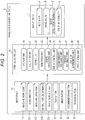
- is a block diagram schematically illustrating a configuration of a travel route generation device;
- Fig. 3
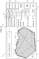
- is a diagram illustrating a travel route and the like generated by the travel route generation device.
- Exemplary embodiments will be described below with reference to the drawings.
- As illustrated in
Fig. 1 , a tractor (one example of "work vehicle") includes components such as a four-wheel travel device 1 that causes a machine body to travel, adriving unit 2 that allows an operator to get in and perform a driving operation, awork device 3 that can perform ground work on a field, a lifting andcoupling mechanism 4 that couples thework device 3 to this machine of the machine body liftably and shakably around a longitudinal shaft center, amobile station 5 that can receive GNSS position information, and a travel route generation device 6 that can perform various operation inputs and information presentations. - Following, further aspects about the travel route generation device 6 are described.
- As illustrated in
Fig. 1 , the travel route generation device 6 is provided in thedriving unit 2. That is, the travel route generation device 6 is a vehicle-mounted device fixed to thedriving unit 2 of the tractor. - As illustrated in
Figs. 2 and3 , the travel route generation device 6 includes aninput device 10 that can input information by an operation such as a touch operation on a screen, adisplay device 11 that can display information, and aterminal controller 12 that performs various types of control. That is, the travel route generation device 6 is a touch-panel operation terminal. - As illustrated in
Fig. 2 , theterminal controller 12 includes astorage unit 20 that stores various pieces of data, anacquisition unit 21 that acquires field data including a field shape F, asetting unit 22 that can set travel work parameters P including headland information on the basis of a manual operation, ageneration unit 23 that generates a travel route R along which the tractor travels on the basis of the field data and the travel work parameters P, and aroute expectation unit 24 that derives route expectation information E about the generated travel route R. - In addition, as illustrated in
Fig. 2 , theterminal controller 12 includes adisplay control unit 25 that causes thedisplay device 11 capable of displaying information to display the acquired field shape F, the generated travel route R, and the derived route expectation information E, arecommendation assignment unit 26 that can collectively assign, on the basis of a manual operation, recommended parameters with which the travel route R generated as the travel work parameters P has the shortest distance, aprevious assignment unit 27 that can collectively assign, on the basis of a manual operation, previous parameters used previously as the travel work parameters P, acollision determination unit 28 that determines whether or not there is collision possibility C of colliding with part of the field when the tractor actually travels along the travel route R, and adrive control unit 29 that outputs a control signal to a machine body controller of the tractor. - The
storage unit 20 illustrated inFig. 2 stores field data in which a field size, the field shape F, GNSS position information at each point, and other information are associated with each other on a field-by-field basis. Theacquisition unit 21 illustrated inFig. 2 acquires the field data from thestorage unit 20. Thesetting unit 22 illustrated inFig. 2 is configured to set the travel work parameters P on the basis of operational input of theinput device 10 or the like. Thesetting unit 22 can set a travel vehicle speed D5 as part of the travel work parameters P. - The
generation unit 23 illustrated inFig. 2 is configured to generate the travel route R along which the tractor travels on the basis of the field data and the travel work parameters P. As illustrated inFigs. 2 and3 , theroute expectation unit 24 is configured to derive an expected work distance ED about the travel route R generated by thegeneration unit 23 as the route expectation information E. In addition, theroute expectation unit 24 is configured to derive an expected work time ET about the travel route R generated as the route expectation information E on the basis of the travel vehicle speed D5. - As illustrated in
Figs. 2 and3 , thedisplay control unit 25 causes thedisplay device 11 to display the derived expected work distance ED. In addition, thedisplay control unit 25 causes thedisplay device 11 to display the derived expected work time ET. When thecollision determination unit 28 determines that the collision possibility C is present, thedisplay control unit 25 causes thedisplay device 11 to display the collision possibility C determined by thecollision determination unit 28. - As illustrated in
Fig. 2 , thedrive control unit 29 is configured to output a control signal to the machine body controller of the tractor on the basis of the travel route R generated by thegeneration unit 23 and the travel work parameters P. The machine body controller performs drive and steering control of thetravel device 1 and the like on the basis of the control signal that is input from thedrive control unit 29. - In the present exemplary embodiment, the recommended parameters assigned by the
recommendation assignment unit 26 and the previous parameters assigned by theprevious assignment unit 27, which can be collectively assigned as the travel work parameters P, are configured such that the collision possibility C can occur in the generated travel route R. - Following, further alternative aspects about the generation of travel route are described.
- To begin with, information regarding a type of this machine is input on the basis of a manual operation of the
input device 10. Accordingly, size information regarding this machine can be obtained (such as a machine body width of this machine, a longitudinal machine body length of this machine, a disposition place of thetravel device 1 in this machine). - Next, information regarding a type of the
work device 3 is input on the basis of a manual operation. Accordingly, size information regarding thework device 3 can be obtained (such as a work width of thework device 3, a longitudinal length of thework device 3, an attachment position of thework device 3 to this machine). - Next, the
acquisition unit 21 acquires the field data about the field to be worked from thestorage unit 20 illustrated inFig. 2 . The field data has been registered in advance. - Next, as illustrated in
Fig. 3 , the travel route generation device 6 displays a route creation screen. In the route creation screen, as items of the travel work parameters P, a headland work count D1 of performing round work, such as round about plowing, a work direction D2 that is a rotation direction of the tractor, a headland lap margin D3 in headland work, a central portion lap margin D4 in central portion work, and the travel vehicle speed D5 at which the tractor travels can be input. The headland work count D1 and the headland lap margin D3 are headland information. A headland width is determined on the basis of the headland work count D1, the headland lap margin D3, and the work width of thework device 3. - When numerical values are input into all the items in which the travel work parameters P can be input by operations, as illustrated in
Fig. 3 , the travel route R is generated on the basis of the travel work parameters P. - As illustrated in
Fig. 3 , the travel route R to be generated includes a central portion route RA along which reciprocating work travel is performed in the central portion of the field, and a headland route RB along which work travel is performed in the headland surrounding the central portion route RA. A straight line section of the central portion route RA is parallel to a reference straight line B that is set in advance. In addition, the travel route R to be generated includes a work start point T1 where work travel is started, and a work end point T2 where work travel is ended. - As illustrated in
Fig. 3 , thedisplay device 11 displays the generated travel route R and the route expectation information E associated with the travel route R. For additional description, as the route expectation information E, the expected work distance ED and the expected work time ET about the generated travel route R are displayed. In addition, in association with the generated travel route R, in a case where there is a possibility of collision with part of a ridge of the field or the like when the actual tractor collides with the travel route R, the collision possibility C is displayed. As illustrated inFig. 3 , the collision possibility C is displayed as a line in each straight line section of an edge of the external shape of the field. In addition, as illustrated inFig. 3 , a message is also displayed together as the collision possibility C, such as "ridge collision is detected." - As illustrated in
Fig. 3 , theinput device 10 is provided with screen buttons and entry fields on the route creation screen. As the screen buttons, aplus button 30 that increases a numerical value by a touch operation, aminus button 31 that decreases a numerical value by a touch operation, arecommendation button 32 that collectively assigns the recommended parameters as the travel work parameters P, and aprevious button 33 that collectively assigns previous parameters as the travel work parameters P. Each entry field enables input of an individual numerical value of each item of the travel work parameters P on the basis of an operation on theplus button 30 and theminus button 31. Performing a touch operation on the entry field of each travel work parameter P enables change in the numerical value of the individual item. Operations of theplus button 30 and theminus button 31 enable increase and decrease in the numerical value of each item, respectively. - When the numerical value of each item is changed by the operation of the
plus button 30 or theminus button 31 illustrated inFig. 3 , the travel route R is generated again and immediately displayed on the basis of the changed travel work parameters P, and in response to this, the route expectation information E (expected work distance ED, expected work time ET) and the collision possibility C are generated again, immediately updated and displayed. - This enables the operator to appropriately evaluate validity of the generated travel route R on the basis of the travel route R, the route expectation information E, and the collision possibility C, which are displayed again every time the travel work parameters P are changed, and to set the travel route R that meets an object.
- Thus, it is possible to cause the tractor to travel automatically in the field on the basis of the travel route R generated by the travel route generation device 6 and the GNSS information received by the
mobile station 5, and to perform ground work (such as tilling and tilling before transplantation) by thework device 3. The present exemplary embodiment is configured to perform travel control of the tractor by complete automatic travel by which rotation of the tractor is also performed automatically. - In addition, the travel of the tractor is temporarily and automatically stopped immediately before a place where the collision possibility C is present in the travel route R.
- Following, alternative embodiments are described:
- Other exemplary embodiments obtained by adding changes to the above-described exemplary embodiment will be described below. A combination of the plurality of following other exemplary embodiments is applicable to the above-described exemplary embodiment, provided that no contradictions arise. Note that the scope of the present invention is not limited to details indicated in each exemplary embodiment.
- (1) The above-described exemplary embodiment has described an example in which the travel route R for one tractor is generated, which is not restrictive. For example, in a case where a plurality of tractors perform cooperation work in the field, the travel routes R for the number of tractors may be generated, and expected work information about the travel routes R and the collision possibility C about the travel routes R may be displayed.
- (2) The above-described exemplary embodiment has described an example in which the expected work distance ED and the expected work time ET are displayed as the route expectation information E, which is not restrictive. For example, other information may be displayed as the route expectation information E, such as a refueling point and time to running out of fuel.
- (3) The above-described exemplary embodiment has described an example in which the recommended parameters and the previous parameters can be collectively assigned on the basis of a manual operation as the travel work parameters P, which is not restrictive. For example, after a condition of avoiding collision with part of the field is added on the basis of a manual operation as the travel work parameters P, avoidance parameters for generating the travel route R with the shortest distance may be able to be assigned collectively. In this case, an avoidance assignment unit for collectively assigning the avoidance parameters by an operation as the travel work parameters P, and an avoidance assignment button for operational input are provided.
- (4) The above-described exemplary embodiment has described an example in which the recommended parameters and the previous parameters can be collectively assigned as the travel work parameters P, which is not restrictive. For example, in order to change the travel work parameters P, it is not necessary that the collective assignment function of parameters is provided.
- (5) The above-described exemplary embodiment has described an example in which the collision possibility C is displayed in each straight line section of the external shape of the field, which is not restrictive. For example, the collision possibility C may be pinpointed as a point in the external shape of the field.
- (6) The above-described exemplary embodiment has described an example in which the collision possibility C is displayed when the travel route R is generated, which is not restrictive. The collision possibility C does not need to be displayed when the travel route R is generated.
- (7) The above-described exemplary embodiment has described an example in which the travel route generation device 6 is a vehicle-mounted device fixed to the
driving unit 2 of the tractor, which is not restrictive. For example, the travel route generation device 6 may be portable that can be carried out of the tractor. In addition, as the travel route generation device 6, two devices may be provided including a vehicle-mounted device and a portable device, and these two devices may be used together. Alternatively, the travel route generation device 6 may be provided as a stationary control computer provided at a remote place distant from the tractor. In this case, the tractor is separately provided with a vehicle-mounted or portable display device, the stationary travel route generation device 6 transmits information to the display device by telecommunication, and the display device displays various pieces of information such as the travel route R and the route expectation information E. - (8) The above-described exemplary embodiment has described an example in which the travel route generation device 6 includes the
display device 11 and theinput device 10, which is not restrictive. For example, the travel route generation device 6, and thedisplay device 11 and theinput device 10 may be provided as different bodies and connected data-exchangeably. - (9) The above-described exemplary embodiment has described an example in which the travel route generation device 6 includes the
storage unit 20 that stores the field data, which is not restrictive. For example, the field data may not be stored in the travel route generation device 6, and theacquisition unit 21 of the travel route generation device 6 may acquire the field data from another device that stores the field data. - (10) The above-described exemplary embodiment has described an example in which the tractor is temporarily stopped immediately before a position at which the collision possibility C is present in the travel route R, which is not restrictive. For example, the tractor may not be stopped even at a position where the collision possibility C is present in the travel route R. In this case, the operator determines whether to stop the tractor or not.
- (11) The above-described exemplary embodiment has described an example in which, when the tractor travels along the travel route R, travel control of the tractor is performed by complete automatic travel by which rotation of the tractor is also performed automatically, which is not restrictive. For example, when the tractor travels along the travel route R, travel control of the tractor may be performed by semiautomatic travel by which straight movement of the tractor is performed automatically and rotation of the tractor is performed manually.
- (12) The above-described exemplary embodiment has described an example in which the tractor includes the four-
wheel travel device 1, which is not restrictive. For example, the four-wheel travel device 1 may be replaced with a crawlertype travel device 1 or a semi crawlertype travel device 1. - (13) The above-described exemplary embodiment has described an example of performing a touch operation on a screen as the
input device 10, which is not restrictive. For example, instead of this, theinput device 10 in which physical buttons are operated or theinput device 10 in which operations of physical buttons and the touch operation on a screen are used together may be used.
- The alternative embodiments can be used for the travel route generation device that generates the travel route for the work vehicle that travels in the field, such as agricultural vehicles including combines and rice transplanters, in addition to the above-described tractor. The features disclosed in this specification, the figures and / or the claims may be material for the realization of various embodiments, taken in isolation or in various combinations thereof.
-
- 6:
- travel route generation device
- 11:
- display device
- 21:
- acquisition unit
- 22:
- setting unit
- 23:
- generation unit
- 24:
- route expectation unit
- 25:
- display control unit
- 26:
- recommendation assignment unit
- 27:
- previous assignment unit
- 28:
- collision determination unit
- C:
- collision possibility
- D5:
- travel vehicle speed
- E:
- route expectation information
- ED:
- expected work distance
- ET:
- expected work time
- F:
- field shape
- P:
- travel work parameter
- R:
- travel route
Claims (7)
- A travel route generation device comprising:- an acquisition unit that acquires field data including a field shape;- a setting unit that allows setting of a travel work parameter including headland information based on a manual operation;- a generation unit that generates a travel route along which a work vehicle travels based on the field data and the travel work parameter;- a route expectation unit that derives route expectation information about the generated travel route; and- a display control unit that causes a display device capable of displaying information to display the acquired field shape, the generated travel route, and the derived route expectation information.
- The travel route generation device according to claim 1, wherein the route expectation unit derives an expected work distance about the travel route to be generated as the route expectation information, and the display control unit causes the display device to display the derived expected work distance.
- The travel route generation device according to claim 1 or 2, wherein the setting unit allows setting of a travel vehicle speed as part of the travel work parameter, the route expectation unit derives expected work time about the travel route to be generated based on the travel vehicle speed as the route expectation information, and the display control unit causes the display device to display the derived expected work time.
- The travel route generation device according to any one of claims 1 to 3, further comprising a recommendation assignment unit capable of collectively assigning, based on a manual operation, a recommended parameter with which the travel route has a shortest distance, the recommended parameter being generated as the travel work parameter.
- The travel route generation device according to any one of claims 1 to 4, further comprising a previous assignment unit capable of collectively assigning, based on a manual operation, a previous parameter that is previously used as the travel work parameter.
- The travel route generation device according to any one of claims 1 to 5, further comprising a collision determination unit that determines whether or not there is a collision possibility of colliding with part of the field when the work vehicle actually travels along the travel route, wherein when the collision determination unit determines that the collision possibility is present, the display control unit causes the display device to display the collision possibility determined by the collision determination unit.
- A method for operating a travel route generation device, comprising:- acquiring field data including a field shape by an acquisition unit;- setting, by a setting unit, a travel work parameter including headland information based on a manual operation;- generating, by a generation unit, a travel route along which a work vehicle travels based on the field data and the travel work parameter;- deriving, by a route expectation unit, route expectation information about the generated travel route; and- causing, by a display control unit, a display device capable of displaying information to display the acquired field shape, the generated travel route, and the derived route expectation information.
Applications Claiming Priority (1)
| Application Number | Priority Date | Filing Date | Title |
|---|---|---|---|
| JP2017008358A JP6887256B2 (en) | 2017-01-20 | 2017-01-20 | Travel route generator |
Publications (2)
| Publication Number | Publication Date |
|---|---|
| EP3351903A1 true EP3351903A1 (en) | 2018-07-25 |
| EP3351903B1 EP3351903B1 (en) | 2025-10-22 |
Family
ID=59067509
Family Applications (1)
| Application Number | Title | Priority Date | Filing Date |
|---|---|---|---|
| EP17175342.9A Active EP3351903B1 (en) | 2017-01-20 | 2017-06-09 | Travel route generation device and a method for operating a travel route generation device |
Country Status (3)
| Country | Link |
|---|---|
| EP (1) | EP3351903B1 (en) |
| JP (1) | JP6887256B2 (en) |
| CN (1) | CN108332762A (en) |
Cited By (2)
| Publication number | Priority date | Publication date | Assignee | Title |
|---|---|---|---|---|
| EP3834601A4 (en) * | 2018-08-07 | 2022-02-09 | Kubota Corporation | HARVESTER, HARVEST SYSTEM, HARVEST SCHEDULE, AND RECORDING MEDIA |
| CN118215392A (en) * | 2021-12-28 | 2024-06-18 | 株式会社久保田 | Agricultural operation auxiliary system, agricultural machinery and agricultural operation auxiliary device |
Families Citing this family (9)
| Publication number | Priority date | Publication date | Assignee | Title |
|---|---|---|---|---|
| JP7334281B2 (en) * | 2018-08-07 | 2023-08-28 | 株式会社クボタ | harvester |
| JP7102333B2 (en) * | 2018-12-26 | 2022-07-19 | 株式会社クボタ | Work vehicle with control device and control device |
| JP7203654B2 (en) * | 2019-03-25 | 2023-01-13 | ヤンマーパワーテクノロジー株式会社 | automatic driving system |
| JP7232417B2 (en) * | 2019-08-30 | 2023-03-03 | 井関農機株式会社 | work vehicle |
| JP7449770B2 (en) * | 2020-04-28 | 2024-03-14 | 三菱重工業株式会社 | Terminal, control system, control method and program |
| JP7605047B2 (en) * | 2021-06-29 | 2024-12-24 | 井関農機株式会社 | Management System |
| JP7649731B2 (en) * | 2021-11-15 | 2025-03-21 | ヤンマーホールディングス株式会社 | Work management method, work management system, and work management program |
| WO2023127266A1 (en) * | 2021-12-28 | 2023-07-06 | 株式会社クボタ | Agricultural work assistance system, agricultural machine, agricultural work assistance device |
| JP7832884B2 (en) * | 2022-11-25 | 2026-03-18 | ヤンマーホールディングス株式会社 | Setup method, automatic driving method, setup system, and setup program |
Citations (4)
| Publication number | Priority date | Publication date | Assignee | Title |
|---|---|---|---|---|
| JPH10243708A (en) | 1997-03-03 | 1998-09-14 | Kubota Corp | Traveling pathway-preparing apparatus for working vehicle and traveling controller |
| WO2015119264A1 (en) * | 2014-02-06 | 2015-08-13 | ヤンマー株式会社 | Remote operation device for parallel travel work system |
| US20160031447A1 (en) * | 2014-08-01 | 2016-02-04 | Kubota Corporation | Driving support system |
| JP2016189791A (en) * | 2016-08-09 | 2016-11-10 | ジオサーフ株式会社 | Field guidance system and field guidance method as well as software and storage medium with software stored therein |
Family Cites Families (5)
| Publication number | Priority date | Publication date | Assignee | Title |
|---|---|---|---|---|
| CN102167038B (en) * | 2010-12-03 | 2013-09-04 | 北京农业信息技术研究中心 | Method and device for generating all-region-covering optimal working path for farmland plot |
| KR20210082559A (en) * | 2014-02-06 | 2021-07-05 | 얀마 파워 테크놀로지 가부시키가이샤 | Parallel travel work system |
| WO2015118730A1 (en) * | 2014-02-06 | 2015-08-13 | ヤンマー株式会社 | Remote operation device for parallel travel work system |
| JP6371137B2 (en) * | 2014-06-27 | 2018-08-08 | 株式会社クボタ | Planting field work machine |
| JP6294839B2 (en) * | 2015-01-06 | 2018-03-14 | ヤンマー株式会社 | Field management system |
-
2017
- 2017-01-20 JP JP2017008358A patent/JP6887256B2/en active Active
- 2017-05-31 CN CN201710405093.XA patent/CN108332762A/en active Pending
- 2017-06-09 EP EP17175342.9A patent/EP3351903B1/en active Active
Patent Citations (4)
| Publication number | Priority date | Publication date | Assignee | Title |
|---|---|---|---|---|
| JPH10243708A (en) | 1997-03-03 | 1998-09-14 | Kubota Corp | Traveling pathway-preparing apparatus for working vehicle and traveling controller |
| WO2015119264A1 (en) * | 2014-02-06 | 2015-08-13 | ヤンマー株式会社 | Remote operation device for parallel travel work system |
| US20160031447A1 (en) * | 2014-08-01 | 2016-02-04 | Kubota Corporation | Driving support system |
| JP2016189791A (en) * | 2016-08-09 | 2016-11-10 | ジオサーフ株式会社 | Field guidance system and field guidance method as well as software and storage medium with software stored therein |
Cited By (3)
| Publication number | Priority date | Publication date | Assignee | Title |
|---|---|---|---|---|
| EP3834601A4 (en) * | 2018-08-07 | 2022-02-09 | Kubota Corporation | HARVESTER, HARVEST SYSTEM, HARVEST SCHEDULE, AND RECORDING MEDIA |
| CN118215392A (en) * | 2021-12-28 | 2024-06-18 | 株式会社久保田 | Agricultural operation auxiliary system, agricultural machinery and agricultural operation auxiliary device |
| US20240324488A1 (en) * | 2021-12-28 | 2024-10-03 | Kubota Corporation | Agricultural work assistance system, agricultural machine, and agricultural work assistance device |
Also Published As
| Publication number | Publication date |
|---|---|
| CN108332762A (en) | 2018-07-27 |
| JP6887256B2 (en) | 2021-06-16 |
| EP3351903B1 (en) | 2025-10-22 |
| JP2018116615A (en) | 2018-07-26 |
Similar Documents
| Publication | Publication Date | Title |
|---|---|---|
| EP3351903A1 (en) | Travel route generation device and a method for operating a travel route generation device | |
| KR102842314B1 (en) | Work screen display system | |
| EP3351079B1 (en) | Work travel management system and method for managing work travel of a work vehicle | |
| CN108205316B (en) | Automatic driving operation vehicle | |
| US7034710B2 (en) | Apparatus and method for displaying information related to a machine | |
| JP2020113062A (en) | Work management system and work machine | |
| JP2021184763A (en) | Field work machine | |
| DE112016003213T5 (en) | MATERIAL TRANSPORT OPERATING SYSTEM FOR COLD MILLING | |
| EP3336646B1 (en) | Automatic traveling work vehicle and method for controlling work traveling for an automatic traveling work vehicle along a travel route | |
| JP2013235460A (en) | Work information extraction system and work information extraction method | |
| DE112010005947T5 (en) | Stereoscopic three-dimensional display device | |
| DE102021104905A1 (en) | AUTOMATIC MODE RESUME SYSTEM FOR A MOBILE MACHINE | |
| US10219423B2 (en) | Travel route generation device and travel route generation method | |
| JP2025078771A (en) | Work machine management method, work machine management system, and work machine management program | |
| KR102140456B1 (en) | Management method using management application for field travel of construction machinery | |
| JP2014038437A (en) | Ground work management system and ground work machine used therein | |
| US12578722B2 (en) | Operation assistance method, operation assistance system, and operation assistance program | |
| JP2020113063A (en) | Work management system and work machine | |
| JP7261716B2 (en) | Operation history data management system for construction machinery | |
| JP2022096949A (en) | Remote control device for plurality of work machine | |
| CN108180920B (en) | Navigation method of vehicle-mounted system and vehicle-mounted system | |
| JP7050874B2 (en) | Work management system | |
| JP2020047286A (en) | Path generation system | |
| JP6918172B2 (en) | Self-driving work vehicle | |
| EP4044080B1 (en) | Work assistance server, work assistance method, and work assistance system |
Legal Events
| Date | Code | Title | Description |
|---|---|---|---|
| PUAI | Public reference made under article 153(3) epc to a published international application that has entered the european phase |
Free format text: ORIGINAL CODE: 0009012 |
|
| STAA | Information on the status of an ep patent application or granted ep patent |
Free format text: STATUS: THE APPLICATION HAS BEEN PUBLISHED |
|
| AK | Designated contracting states |
Kind code of ref document: A1 Designated state(s): AL AT BE BG CH CY CZ DE DK EE ES FI FR GB GR HR HU IE IS IT LI LT LU LV MC MK MT NL NO PL PT RO RS SE SI SK SM TR |
|
| AX | Request for extension of the european patent |
Extension state: BA ME |
|
| STAA | Information on the status of an ep patent application or granted ep patent |
Free format text: STATUS: REQUEST FOR EXAMINATION WAS MADE |
|
| 17P | Request for examination filed |
Effective date: 20190124 |
|
| RBV | Designated contracting states (corrected) |
Designated state(s): AL AT BE BG CH CY CZ DE DK EE ES FI FR GB GR HR HU IE IS IT LI LT LU LV MC MK MT NL NO PL PT RO RS SE SI SK SM TR |
|
| STAA | Information on the status of an ep patent application or granted ep patent |
Free format text: STATUS: EXAMINATION IS IN PROGRESS |
|
| 17Q | First examination report despatched |
Effective date: 20210422 |
|
| GRAP | Despatch of communication of intention to grant a patent |
Free format text: ORIGINAL CODE: EPIDOSNIGR1 |
|
| STAA | Information on the status of an ep patent application or granted ep patent |
Free format text: STATUS: GRANT OF PATENT IS INTENDED |
|
| INTG | Intention to grant announced |
Effective date: 20250522 |
|
| GRAS | Grant fee paid |
Free format text: ORIGINAL CODE: EPIDOSNIGR3 |
|
| GRAA | (expected) grant |
Free format text: ORIGINAL CODE: 0009210 |
|
| STAA | Information on the status of an ep patent application or granted ep patent |
Free format text: STATUS: THE PATENT HAS BEEN GRANTED |
|
| AK | Designated contracting states |
Kind code of ref document: B1 Designated state(s): AL AT BE BG CH CY CZ DE DK EE ES FI FR GB GR HR HU IE IS IT LI LT LU LV MC MK MT NL NO PL PT RO RS SE SI SK SM TR |
|
| REG | Reference to a national code |
Ref country code: CH Ref legal event code: F10 Free format text: ST27 STATUS EVENT CODE: U-0-0-F10-F00 (AS PROVIDED BY THE NATIONAL OFFICE) Effective date: 20251022 Ref country code: GB Ref legal event code: FG4D |
|
| REG | Reference to a national code |
Ref country code: DE Ref legal event code: R096 Ref document number: 602017092285 Country of ref document: DE |
|
| REG | Reference to a national code |
Ref country code: IE Ref legal event code: FG4D |
|
| REG | Reference to a national code |
Ref country code: NL Ref legal event code: MP Effective date: 20251022 |
|
| PG25 | Lapsed in a contracting state [announced via postgrant information from national office to epo] |
Ref country code: NL Free format text: LAPSE BECAUSE OF FAILURE TO SUBMIT A TRANSLATION OF THE DESCRIPTION OR TO PAY THE FEE WITHIN THE PRESCRIBED TIME-LIMIT Effective date: 20251022 |
|
| PG25 | Lapsed in a contracting state [announced via postgrant information from national office to epo] |
Ref country code: ES Free format text: LAPSE BECAUSE OF FAILURE TO SUBMIT A TRANSLATION OF THE DESCRIPTION OR TO PAY THE FEE WITHIN THE PRESCRIBED TIME-LIMIT Effective date: 20251022 |
|
| REG | Reference to a national code |
Ref country code: LT Ref legal event code: MG9D |
|
| PG25 | Lapsed in a contracting state [announced via postgrant information from national office to epo] |
Ref country code: NO Free format text: LAPSE BECAUSE OF FAILURE TO SUBMIT A TRANSLATION OF THE DESCRIPTION OR TO PAY THE FEE WITHIN THE PRESCRIBED TIME-LIMIT Effective date: 20260122 |
|
| PG25 | Lapsed in a contracting state [announced via postgrant information from national office to epo] |
Ref country code: AT Free format text: LAPSE BECAUSE OF FAILURE TO SUBMIT A TRANSLATION OF THE DESCRIPTION OR TO PAY THE FEE WITHIN THE PRESCRIBED TIME-LIMIT Effective date: 20251022 Ref country code: HR Free format text: LAPSE BECAUSE OF FAILURE TO SUBMIT A TRANSLATION OF THE DESCRIPTION OR TO PAY THE FEE WITHIN THE PRESCRIBED TIME-LIMIT Effective date: 20251022 Ref country code: FI Free format text: LAPSE BECAUSE OF FAILURE TO SUBMIT A TRANSLATION OF THE DESCRIPTION OR TO PAY THE FEE WITHIN THE PRESCRIBED TIME-LIMIT Effective date: 20251022 |
|
| REG | Reference to a national code |
Ref country code: AT Ref legal event code: MK05 Ref document number: 1849486 Country of ref document: AT Kind code of ref document: T Effective date: 20251022 |
|
| PG25 | Lapsed in a contracting state [announced via postgrant information from national office to epo] |
Ref country code: RS Free format text: LAPSE BECAUSE OF FAILURE TO SUBMIT A TRANSLATION OF THE DESCRIPTION OR TO PAY THE FEE WITHIN THE PRESCRIBED TIME-LIMIT Effective date: 20260122 |
|
| PG25 | Lapsed in a contracting state [announced via postgrant information from national office to epo] |
Ref country code: IS Free format text: LAPSE BECAUSE OF FAILURE TO SUBMIT A TRANSLATION OF THE DESCRIPTION OR TO PAY THE FEE WITHIN THE PRESCRIBED TIME-LIMIT Effective date: 20260222 |
|
| PG25 | Lapsed in a contracting state [announced via postgrant information from national office to epo] |
Ref country code: PT Free format text: LAPSE BECAUSE OF FAILURE TO SUBMIT A TRANSLATION OF THE DESCRIPTION OR TO PAY THE FEE WITHIN THE PRESCRIBED TIME-LIMIT Effective date: 20260223 |
|
| PG25 | Lapsed in a contracting state [announced via postgrant information from national office to epo] |
Ref country code: PL Free format text: LAPSE BECAUSE OF FAILURE TO SUBMIT A TRANSLATION OF THE DESCRIPTION OR TO PAY THE FEE WITHIN THE PRESCRIBED TIME-LIMIT Effective date: 20251022 |
|
| PG25 | Lapsed in a contracting state [announced via postgrant information from national office to epo] |
Ref country code: LV Free format text: LAPSE BECAUSE OF FAILURE TO SUBMIT A TRANSLATION OF THE DESCRIPTION OR TO PAY THE FEE WITHIN THE PRESCRIBED TIME-LIMIT Effective date: 20251022 |