EP3351882A1 - Compression train including one centrifugal compressor and lng plant - Google Patents
Compression train including one centrifugal compressor and lng plant Download PDFInfo
- Publication number
- EP3351882A1 EP3351882A1 EP18152558.5A EP18152558A EP3351882A1 EP 3351882 A1 EP3351882 A1 EP 3351882A1 EP 18152558 A EP18152558 A EP 18152558A EP 3351882 A1 EP3351882 A1 EP 3351882A1
- Authority
- EP
- European Patent Office
- Prior art keywords
- compression
- train according
- compression train
- compressor
- section
- Prior art date
- Legal status (The legal status is an assumption and is not a legal conclusion. Google has not performed a legal analysis and makes no representation as to the accuracy of the status listed.)
- Granted
Links
Images


Classifications
-
- F—MECHANICAL ENGINEERING; LIGHTING; HEATING; WEAPONS; BLASTING
- F25—REFRIGERATION OR COOLING; COMBINED HEATING AND REFRIGERATION SYSTEMS; HEAT PUMP SYSTEMS; MANUFACTURE OR STORAGE OF ICE; LIQUEFACTION SOLIDIFICATION OF GASES
- F25J—LIQUEFACTION, SOLIDIFICATION OR SEPARATION OF GASES OR GASEOUS OR LIQUEFIED GASEOUS MIXTURES BY PRESSURE AND COLD TREATMENT OR BY BRINGING THEM INTO THE SUPERCRITICAL STATE
- F25J3/00—Processes or apparatus for separating the constituents of gaseous or liquefied gaseous mixtures involving the use of liquefaction or solidification
- F25J3/02—Processes or apparatus for separating the constituents of gaseous or liquefied gaseous mixtures involving the use of liquefaction or solidification by rectification, i.e. by continuous interchange of heat and material between a vapour stream and a liquid stream
- F25J3/04—Processes or apparatus for separating the constituents of gaseous or liquefied gaseous mixtures involving the use of liquefaction or solidification by rectification, i.e. by continuous interchange of heat and material between a vapour stream and a liquid stream for air
- F25J3/04006—Providing pressurised feed air or process streams within or from the air fractionation unit
- F25J3/04109—Arrangements of compressors and /or their drivers
- F25J3/04145—Mechanically coupling of different compressors of the air fractionation process to the same driver(s)
-
- F—MECHANICAL ENGINEERING; LIGHTING; HEATING; WEAPONS; BLASTING
- F04—POSITIVE - DISPLACEMENT MACHINES FOR LIQUIDS; PUMPS FOR LIQUIDS OR ELASTIC FLUIDS
- F04D—NON-POSITIVE-DISPLACEMENT PUMPS
- F04D17/00—Radial-flow pumps, e.g. centrifugal pumps; Helico-centrifugal pumps
- F04D17/08—Centrifugal pumps
- F04D17/10—Centrifugal pumps for compressing or evacuating
- F04D17/12—Multi-stage pumps
-
- F—MECHANICAL ENGINEERING; LIGHTING; HEATING; WEAPONS; BLASTING
- F04—POSITIVE - DISPLACEMENT MACHINES FOR LIQUIDS; PUMPS FOR LIQUIDS OR ELASTIC FLUIDS
- F04D—NON-POSITIVE-DISPLACEMENT PUMPS
- F04D17/00—Radial-flow pumps, e.g. centrifugal pumps; Helico-centrifugal pumps
- F04D17/08—Centrifugal pumps
- F04D17/10—Centrifugal pumps for compressing or evacuating
- F04D17/12—Multi-stage pumps
- F04D17/122—Multi-stage pumps the individual rotor discs being, one for each stage, on a common shaft and axially spaced, e.g. conventional centrifugal multi- stage compressors
-
- F—MECHANICAL ENGINEERING; LIGHTING; HEATING; WEAPONS; BLASTING
- F04—POSITIVE - DISPLACEMENT MACHINES FOR LIQUIDS; PUMPS FOR LIQUIDS OR ELASTIC FLUIDS
- F04D—NON-POSITIVE-DISPLACEMENT PUMPS
- F04D29/00—Details, component parts, or accessories
- F04D29/08—Sealings
- F04D29/083—Sealings especially adapted for elastic fluid pumps
-
- F—MECHANICAL ENGINEERING; LIGHTING; HEATING; WEAPONS; BLASTING
- F04—POSITIVE - DISPLACEMENT MACHINES FOR LIQUIDS; PUMPS FOR LIQUIDS OR ELASTIC FLUIDS
- F04D—NON-POSITIVE-DISPLACEMENT PUMPS
- F04D29/00—Details, component parts, or accessories
- F04D29/40—Casings; Connections of working fluid
- F04D29/42—Casings; Connections of working fluid for radial or helico-centrifugal pumps
- F04D29/4206—Casings; Connections of working fluid for radial or helico-centrifugal pumps especially adapted for elastic fluid pumps
-
- F—MECHANICAL ENGINEERING; LIGHTING; HEATING; WEAPONS; BLASTING
- F04—POSITIVE - DISPLACEMENT MACHINES FOR LIQUIDS; PUMPS FOR LIQUIDS OR ELASTIC FLUIDS
- F04D—NON-POSITIVE-DISPLACEMENT PUMPS
- F04D29/00—Details, component parts, or accessories
- F04D29/58—Cooling; Heating; Diminishing heat transfer
- F04D29/582—Cooling; Heating; Diminishing heat transfer specially adapted for elastic fluid pumps
- F04D29/5826—Cooling at least part of the working fluid in a heat exchanger
-
- F—MECHANICAL ENGINEERING; LIGHTING; HEATING; WEAPONS; BLASTING
- F25—REFRIGERATION OR COOLING; COMBINED HEATING AND REFRIGERATION SYSTEMS; HEAT PUMP SYSTEMS; MANUFACTURE OR STORAGE OF ICE; LIQUEFACTION SOLIDIFICATION OF GASES
- F25B—REFRIGERATION MACHINES, PLANTS OR SYSTEMS; COMBINED HEATING AND REFRIGERATION SYSTEMS; HEAT PUMP SYSTEMS
- F25B45/00—Arrangements for charging or discharging refrigerant
-
- F—MECHANICAL ENGINEERING; LIGHTING; HEATING; WEAPONS; BLASTING
- F25—REFRIGERATION OR COOLING; COMBINED HEATING AND REFRIGERATION SYSTEMS; HEAT PUMP SYSTEMS; MANUFACTURE OR STORAGE OF ICE; LIQUEFACTION SOLIDIFICATION OF GASES
- F25J—LIQUEFACTION, SOLIDIFICATION OR SEPARATION OF GASES OR GASEOUS OR LIQUEFIED GASEOUS MIXTURES BY PRESSURE AND COLD TREATMENT OR BY BRINGING THEM INTO THE SUPERCRITICAL STATE
- F25J1/00—Processes or apparatus for liquefying or solidifying gases or gaseous mixtures
- F25J1/0002—Processes or apparatus for liquefying or solidifying gases or gaseous mixtures characterised by the fluid to be liquefied
- F25J1/0022—Hydrocarbons, e.g. natural gas
-
- F—MECHANICAL ENGINEERING; LIGHTING; HEATING; WEAPONS; BLASTING
- F25—REFRIGERATION OR COOLING; COMBINED HEATING AND REFRIGERATION SYSTEMS; HEAT PUMP SYSTEMS; MANUFACTURE OR STORAGE OF ICE; LIQUEFACTION SOLIDIFICATION OF GASES
- F25J—LIQUEFACTION, SOLIDIFICATION OR SEPARATION OF GASES OR GASEOUS OR LIQUEFIED GASEOUS MIXTURES BY PRESSURE AND COLD TREATMENT OR BY BRINGING THEM INTO THE SUPERCRITICAL STATE
- F25J1/00—Processes or apparatus for liquefying or solidifying gases or gaseous mixtures
- F25J1/003—Processes or apparatus for liquefying or solidifying gases or gaseous mixtures characterised by the kind of cold generation within the liquefaction unit for compensating heat leaks and liquid production
- F25J1/0047—Processes or apparatus for liquefying or solidifying gases or gaseous mixtures characterised by the kind of cold generation within the liquefaction unit for compensating heat leaks and liquid production using an "external" refrigerant stream in a closed vapor compression cycle
- F25J1/0052—Processes or apparatus for liquefying or solidifying gases or gaseous mixtures characterised by the kind of cold generation within the liquefaction unit for compensating heat leaks and liquid production using an "external" refrigerant stream in a closed vapor compression cycle by vaporising a liquid refrigerant stream
-
- F—MECHANICAL ENGINEERING; LIGHTING; HEATING; WEAPONS; BLASTING
- F25—REFRIGERATION OR COOLING; COMBINED HEATING AND REFRIGERATION SYSTEMS; HEAT PUMP SYSTEMS; MANUFACTURE OR STORAGE OF ICE; LIQUEFACTION SOLIDIFICATION OF GASES
- F25J—LIQUEFACTION, SOLIDIFICATION OR SEPARATION OF GASES OR GASEOUS OR LIQUEFIED GASEOUS MIXTURES BY PRESSURE AND COLD TREATMENT OR BY BRINGING THEM INTO THE SUPERCRITICAL STATE
- F25J1/00—Processes or apparatus for liquefying or solidifying gases or gaseous mixtures
- F25J1/003—Processes or apparatus for liquefying or solidifying gases or gaseous mixtures characterised by the kind of cold generation within the liquefaction unit for compensating heat leaks and liquid production
- F25J1/0047—Processes or apparatus for liquefying or solidifying gases or gaseous mixtures characterised by the kind of cold generation within the liquefaction unit for compensating heat leaks and liquid production using an "external" refrigerant stream in a closed vapor compression cycle
- F25J1/0052—Processes or apparatus for liquefying or solidifying gases or gaseous mixtures characterised by the kind of cold generation within the liquefaction unit for compensating heat leaks and liquid production using an "external" refrigerant stream in a closed vapor compression cycle by vaporising a liquid refrigerant stream
- F25J1/0055—Processes or apparatus for liquefying or solidifying gases or gaseous mixtures characterised by the kind of cold generation within the liquefaction unit for compensating heat leaks and liquid production using an "external" refrigerant stream in a closed vapor compression cycle by vaporising a liquid refrigerant stream originating from an incorporated cascade
-
- F—MECHANICAL ENGINEERING; LIGHTING; HEATING; WEAPONS; BLASTING
- F25—REFRIGERATION OR COOLING; COMBINED HEATING AND REFRIGERATION SYSTEMS; HEAT PUMP SYSTEMS; MANUFACTURE OR STORAGE OF ICE; LIQUEFACTION SOLIDIFICATION OF GASES
- F25J—LIQUEFACTION, SOLIDIFICATION OR SEPARATION OF GASES OR GASEOUS OR LIQUEFIED GASEOUS MIXTURES BY PRESSURE AND COLD TREATMENT OR BY BRINGING THEM INTO THE SUPERCRITICAL STATE
- F25J1/00—Processes or apparatus for liquefying or solidifying gases or gaseous mixtures
- F25J1/006—Processes or apparatus for liquefying or solidifying gases or gaseous mixtures characterised by the refrigerant fluid used
- F25J1/008—Hydrocarbons
- F25J1/0082—Methane
-
- F—MECHANICAL ENGINEERING; LIGHTING; HEATING; WEAPONS; BLASTING
- F25—REFRIGERATION OR COOLING; COMBINED HEATING AND REFRIGERATION SYSTEMS; HEAT PUMP SYSTEMS; MANUFACTURE OR STORAGE OF ICE; LIQUEFACTION SOLIDIFICATION OF GASES
- F25J—LIQUEFACTION, SOLIDIFICATION OR SEPARATION OF GASES OR GASEOUS OR LIQUEFIED GASEOUS MIXTURES BY PRESSURE AND COLD TREATMENT OR BY BRINGING THEM INTO THE SUPERCRITICAL STATE
- F25J1/00—Processes or apparatus for liquefying or solidifying gases or gaseous mixtures
- F25J1/006—Processes or apparatus for liquefying or solidifying gases or gaseous mixtures characterised by the refrigerant fluid used
- F25J1/008—Hydrocarbons
- F25J1/0085—Ethane; Ethylene
-
- F—MECHANICAL ENGINEERING; LIGHTING; HEATING; WEAPONS; BLASTING
- F25—REFRIGERATION OR COOLING; COMBINED HEATING AND REFRIGERATION SYSTEMS; HEAT PUMP SYSTEMS; MANUFACTURE OR STORAGE OF ICE; LIQUEFACTION SOLIDIFICATION OF GASES
- F25J—LIQUEFACTION, SOLIDIFICATION OR SEPARATION OF GASES OR GASEOUS OR LIQUEFIED GASEOUS MIXTURES BY PRESSURE AND COLD TREATMENT OR BY BRINGING THEM INTO THE SUPERCRITICAL STATE
- F25J1/00—Processes or apparatus for liquefying or solidifying gases or gaseous mixtures
- F25J1/006—Processes or apparatus for liquefying or solidifying gases or gaseous mixtures characterised by the refrigerant fluid used
- F25J1/008—Hydrocarbons
- F25J1/0087—Propane; Propylene
-
- F—MECHANICAL ENGINEERING; LIGHTING; HEATING; WEAPONS; BLASTING
- F25—REFRIGERATION OR COOLING; COMBINED HEATING AND REFRIGERATION SYSTEMS; HEAT PUMP SYSTEMS; MANUFACTURE OR STORAGE OF ICE; LIQUEFACTION SOLIDIFICATION OF GASES
- F25J—LIQUEFACTION, SOLIDIFICATION OR SEPARATION OF GASES OR GASEOUS OR LIQUEFIED GASEOUS MIXTURES BY PRESSURE AND COLD TREATMENT OR BY BRINGING THEM INTO THE SUPERCRITICAL STATE
- F25J1/00—Processes or apparatus for liquefying or solidifying gases or gaseous mixtures
- F25J1/02—Processes or apparatus for liquefying or solidifying gases or gaseous mixtures requiring the use of refrigeration, e.g. of helium or hydrogen ; Details and kind of the refrigeration system used; Integration with other units or processes; Controlling aspects of the process
- F25J1/0203—Processes or apparatus for liquefying or solidifying gases or gaseous mixtures requiring the use of refrigeration, e.g. of helium or hydrogen ; Details and kind of the refrigeration system used; Integration with other units or processes; Controlling aspects of the process using a single-component refrigerant [SCR] fluid in a closed vapor compression cycle
- F25J1/0207—Processes or apparatus for liquefying or solidifying gases or gaseous mixtures requiring the use of refrigeration, e.g. of helium or hydrogen ; Details and kind of the refrigeration system used; Integration with other units or processes; Controlling aspects of the process using a single-component refrigerant [SCR] fluid in a closed vapor compression cycle as at least a three level SCR refrigeration cascade
-
- F—MECHANICAL ENGINEERING; LIGHTING; HEATING; WEAPONS; BLASTING
- F25—REFRIGERATION OR COOLING; COMBINED HEATING AND REFRIGERATION SYSTEMS; HEAT PUMP SYSTEMS; MANUFACTURE OR STORAGE OF ICE; LIQUEFACTION SOLIDIFICATION OF GASES
- F25J—LIQUEFACTION, SOLIDIFICATION OR SEPARATION OF GASES OR GASEOUS OR LIQUEFIED GASEOUS MIXTURES BY PRESSURE AND COLD TREATMENT OR BY BRINGING THEM INTO THE SUPERCRITICAL STATE
- F25J1/00—Processes or apparatus for liquefying or solidifying gases or gaseous mixtures
- F25J1/02—Processes or apparatus for liquefying or solidifying gases or gaseous mixtures requiring the use of refrigeration, e.g. of helium or hydrogen ; Details and kind of the refrigeration system used; Integration with other units or processes; Controlling aspects of the process
- F25J1/0211—Processes or apparatus for liquefying or solidifying gases or gaseous mixtures requiring the use of refrigeration, e.g. of helium or hydrogen ; Details and kind of the refrigeration system used; Integration with other units or processes; Controlling aspects of the process using a multi-component refrigerant [MCR] fluid in a closed vapor compression cycle
- F25J1/0214—Processes or apparatus for liquefying or solidifying gases or gaseous mixtures requiring the use of refrigeration, e.g. of helium or hydrogen ; Details and kind of the refrigeration system used; Integration with other units or processes; Controlling aspects of the process using a multi-component refrigerant [MCR] fluid in a closed vapor compression cycle as a dual level refrigeration cascade with at least one MCR cycle
- F25J1/0215—Processes or apparatus for liquefying or solidifying gases or gaseous mixtures requiring the use of refrigeration, e.g. of helium or hydrogen ; Details and kind of the refrigeration system used; Integration with other units or processes; Controlling aspects of the process using a multi-component refrigerant [MCR] fluid in a closed vapor compression cycle as a dual level refrigeration cascade with at least one MCR cycle with one SCR cycle
- F25J1/0216—Processes or apparatus for liquefying or solidifying gases or gaseous mixtures requiring the use of refrigeration, e.g. of helium or hydrogen ; Details and kind of the refrigeration system used; Integration with other units or processes; Controlling aspects of the process using a multi-component refrigerant [MCR] fluid in a closed vapor compression cycle as a dual level refrigeration cascade with at least one MCR cycle with one SCR cycle using a C3 pre-cooling cycle
-
- F—MECHANICAL ENGINEERING; LIGHTING; HEATING; WEAPONS; BLASTING
- F25—REFRIGERATION OR COOLING; COMBINED HEATING AND REFRIGERATION SYSTEMS; HEAT PUMP SYSTEMS; MANUFACTURE OR STORAGE OF ICE; LIQUEFACTION SOLIDIFICATION OF GASES
- F25J—LIQUEFACTION, SOLIDIFICATION OR SEPARATION OF GASES OR GASEOUS OR LIQUEFIED GASEOUS MIXTURES BY PRESSURE AND COLD TREATMENT OR BY BRINGING THEM INTO THE SUPERCRITICAL STATE
- F25J1/00—Processes or apparatus for liquefying or solidifying gases or gaseous mixtures
- F25J1/02—Processes or apparatus for liquefying or solidifying gases or gaseous mixtures requiring the use of refrigeration, e.g. of helium or hydrogen ; Details and kind of the refrigeration system used; Integration with other units or processes; Controlling aspects of the process
- F25J1/0243—Start-up or control of the process; Details of the apparatus used; Details of the refrigerant compression system used
- F25J1/0279—Compression of refrigerant or internal recycle fluid, e.g. kind of compressor, accumulator, suction drum etc.
-
- F—MECHANICAL ENGINEERING; LIGHTING; HEATING; WEAPONS; BLASTING
- F25—REFRIGERATION OR COOLING; COMBINED HEATING AND REFRIGERATION SYSTEMS; HEAT PUMP SYSTEMS; MANUFACTURE OR STORAGE OF ICE; LIQUEFACTION SOLIDIFICATION OF GASES
- F25J—LIQUEFACTION, SOLIDIFICATION OR SEPARATION OF GASES OR GASEOUS OR LIQUEFIED GASEOUS MIXTURES BY PRESSURE AND COLD TREATMENT OR BY BRINGING THEM INTO THE SUPERCRITICAL STATE
- F25J1/00—Processes or apparatus for liquefying or solidifying gases or gaseous mixtures
- F25J1/02—Processes or apparatus for liquefying or solidifying gases or gaseous mixtures requiring the use of refrigeration, e.g. of helium or hydrogen ; Details and kind of the refrigeration system used; Integration with other units or processes; Controlling aspects of the process
- F25J1/0243—Start-up or control of the process; Details of the apparatus used; Details of the refrigerant compression system used
- F25J1/0279—Compression of refrigerant or internal recycle fluid, e.g. kind of compressor, accumulator, suction drum etc.
- F25J1/0281—Compression of refrigerant or internal recycle fluid, e.g. kind of compressor, accumulator, suction drum etc. characterised by the type of prime driver, e.g. hot gas expander
- F25J1/0283—Gas turbine as the prime mechanical driver
-
- F—MECHANICAL ENGINEERING; LIGHTING; HEATING; WEAPONS; BLASTING
- F25—REFRIGERATION OR COOLING; COMBINED HEATING AND REFRIGERATION SYSTEMS; HEAT PUMP SYSTEMS; MANUFACTURE OR STORAGE OF ICE; LIQUEFACTION SOLIDIFICATION OF GASES
- F25J—LIQUEFACTION, SOLIDIFICATION OR SEPARATION OF GASES OR GASEOUS OR LIQUEFIED GASEOUS MIXTURES BY PRESSURE AND COLD TREATMENT OR BY BRINGING THEM INTO THE SUPERCRITICAL STATE
- F25J1/00—Processes or apparatus for liquefying or solidifying gases or gaseous mixtures
- F25J1/02—Processes or apparatus for liquefying or solidifying gases or gaseous mixtures requiring the use of refrigeration, e.g. of helium or hydrogen ; Details and kind of the refrigeration system used; Integration with other units or processes; Controlling aspects of the process
- F25J1/0243—Start-up or control of the process; Details of the apparatus used; Details of the refrigerant compression system used
- F25J1/0279—Compression of refrigerant or internal recycle fluid, e.g. kind of compressor, accumulator, suction drum etc.
- F25J1/0281—Compression of refrigerant or internal recycle fluid, e.g. kind of compressor, accumulator, suction drum etc. characterised by the type of prime driver, e.g. hot gas expander
- F25J1/0284—Electrical motor as the prime mechanical driver
-
- F—MECHANICAL ENGINEERING; LIGHTING; HEATING; WEAPONS; BLASTING
- F25—REFRIGERATION OR COOLING; COMBINED HEATING AND REFRIGERATION SYSTEMS; HEAT PUMP SYSTEMS; MANUFACTURE OR STORAGE OF ICE; LIQUEFACTION SOLIDIFICATION OF GASES
- F25J—LIQUEFACTION, SOLIDIFICATION OR SEPARATION OF GASES OR GASEOUS OR LIQUEFIED GASEOUS MIXTURES BY PRESSURE AND COLD TREATMENT OR BY BRINGING THEM INTO THE SUPERCRITICAL STATE
- F25J1/00—Processes or apparatus for liquefying or solidifying gases or gaseous mixtures
- F25J1/02—Processes or apparatus for liquefying or solidifying gases or gaseous mixtures requiring the use of refrigeration, e.g. of helium or hydrogen ; Details and kind of the refrigeration system used; Integration with other units or processes; Controlling aspects of the process
- F25J1/0243—Start-up or control of the process; Details of the apparatus used; Details of the refrigerant compression system used
- F25J1/0279—Compression of refrigerant or internal recycle fluid, e.g. kind of compressor, accumulator, suction drum etc.
- F25J1/0292—Refrigerant compression by cold or cryogenic suction of the refrigerant gas
-
- F—MECHANICAL ENGINEERING; LIGHTING; HEATING; WEAPONS; BLASTING
- F25—REFRIGERATION OR COOLING; COMBINED HEATING AND REFRIGERATION SYSTEMS; HEAT PUMP SYSTEMS; MANUFACTURE OR STORAGE OF ICE; LIQUEFACTION SOLIDIFICATION OF GASES
- F25J—LIQUEFACTION, SOLIDIFICATION OR SEPARATION OF GASES OR GASEOUS OR LIQUEFIED GASEOUS MIXTURES BY PRESSURE AND COLD TREATMENT OR BY BRINGING THEM INTO THE SUPERCRITICAL STATE
- F25J3/00—Processes or apparatus for separating the constituents of gaseous or liquefied gaseous mixtures involving the use of liquefaction or solidification
- F25J3/02—Processes or apparatus for separating the constituents of gaseous or liquefied gaseous mixtures involving the use of liquefaction or solidification by rectification, i.e. by continuous interchange of heat and material between a vapour stream and a liquid stream
- F25J3/04—Processes or apparatus for separating the constituents of gaseous or liquefied gaseous mixtures involving the use of liquefaction or solidification by rectification, i.e. by continuous interchange of heat and material between a vapour stream and a liquid stream for air
- F25J3/04006—Providing pressurised feed air or process streams within or from the air fractionation unit
- F25J3/04109—Arrangements of compressors and /or their drivers
- F25J3/04115—Arrangements of compressors and /or their drivers characterised by the type of prime driver, e.g. hot gas expander
- F25J3/04127—Gas turbine as the prime mechanical driver
-
- F—MECHANICAL ENGINEERING; LIGHTING; HEATING; WEAPONS; BLASTING
- F25—REFRIGERATION OR COOLING; COMBINED HEATING AND REFRIGERATION SYSTEMS; HEAT PUMP SYSTEMS; MANUFACTURE OR STORAGE OF ICE; LIQUEFACTION SOLIDIFICATION OF GASES
- F25J—LIQUEFACTION, SOLIDIFICATION OR SEPARATION OF GASES OR GASEOUS OR LIQUEFIED GASEOUS MIXTURES BY PRESSURE AND COLD TREATMENT OR BY BRINGING THEM INTO THE SUPERCRITICAL STATE
- F25J3/00—Processes or apparatus for separating the constituents of gaseous or liquefied gaseous mixtures involving the use of liquefaction or solidification
- F25J3/02—Processes or apparatus for separating the constituents of gaseous or liquefied gaseous mixtures involving the use of liquefaction or solidification by rectification, i.e. by continuous interchange of heat and material between a vapour stream and a liquid stream
- F25J3/04—Processes or apparatus for separating the constituents of gaseous or liquefied gaseous mixtures involving the use of liquefaction or solidification by rectification, i.e. by continuous interchange of heat and material between a vapour stream and a liquid stream for air
- F25J3/04006—Providing pressurised feed air or process streams within or from the air fractionation unit
- F25J3/04109—Arrangements of compressors and /or their drivers
- F25J3/04115—Arrangements of compressors and /or their drivers characterised by the type of prime driver, e.g. hot gas expander
- F25J3/04133—Electrical motor as the prime mechanical driver
-
- F—MECHANICAL ENGINEERING; LIGHTING; HEATING; WEAPONS; BLASTING
- F25—REFRIGERATION OR COOLING; COMBINED HEATING AND REFRIGERATION SYSTEMS; HEAT PUMP SYSTEMS; MANUFACTURE OR STORAGE OF ICE; LIQUEFACTION SOLIDIFICATION OF GASES
- F25J—LIQUEFACTION, SOLIDIFICATION OR SEPARATION OF GASES OR GASEOUS OR LIQUEFIED GASEOUS MIXTURES BY PRESSURE AND COLD TREATMENT OR BY BRINGING THEM INTO THE SUPERCRITICAL STATE
- F25J2220/00—Processes or apparatus involving steps for the removal of impurities
- F25J2220/60—Separating impurities from natural gas, e.g. mercury, cyclic hydrocarbons
- F25J2220/64—Separating heavy hydrocarbons, e.g. NGL, LPG, C4+ hydrocarbons or heavy condensates in general
-
- F—MECHANICAL ENGINEERING; LIGHTING; HEATING; WEAPONS; BLASTING
- F25—REFRIGERATION OR COOLING; COMBINED HEATING AND REFRIGERATION SYSTEMS; HEAT PUMP SYSTEMS; MANUFACTURE OR STORAGE OF ICE; LIQUEFACTION SOLIDIFICATION OF GASES
- F25J—LIQUEFACTION, SOLIDIFICATION OR SEPARATION OF GASES OR GASEOUS OR LIQUEFIED GASEOUS MIXTURES BY PRESSURE AND COLD TREATMENT OR BY BRINGING THEM INTO THE SUPERCRITICAL STATE
- F25J2230/00—Processes or apparatus involving steps for increasing the pressure of gaseous process streams
- F25J2230/20—Integrated compressor and process expander; Gear box arrangement; Multiple compressors on a common shaft
-
- F—MECHANICAL ENGINEERING; LIGHTING; HEATING; WEAPONS; BLASTING
- F25—REFRIGERATION OR COOLING; COMBINED HEATING AND REFRIGERATION SYSTEMS; HEAT PUMP SYSTEMS; MANUFACTURE OR STORAGE OF ICE; LIQUEFACTION SOLIDIFICATION OF GASES
- F25J—LIQUEFACTION, SOLIDIFICATION OR SEPARATION OF GASES OR GASEOUS OR LIQUEFIED GASEOUS MIXTURES BY PRESSURE AND COLD TREATMENT OR BY BRINGING THEM INTO THE SUPERCRITICAL STATE
- F25J2290/00—Other details not covered by groups F25J2200/00 - F25J2280/00
- F25J2290/12—Particular process parameters like pressure, temperature, ratios
Definitions
- Improvements may derive from e.g. the structure and/or operation of the machines, the connection of machines, or the combination of machines (for example trains of machines).
- Improvements may consist in e.g. increased efficiency and/or reduced losses, increased production and/or decreased wastes, increased functions, reduced cost, reduced size and/or footprint.
- the AP-C3MR® (also called “C3MR”) process uses a pure-refrigerant (“C3”), i.e. propane, and a mixed refrigerant (“MR”), i.e. a mixture of typically propane, ethylene, and methane; this process is a 2-cycles liquefaction technology: (one) pure-refrigerant and (one) mixed-refrigerant.
- C3 pure-refrigerant
- MR mixed refrigerant
- Fig. 1 shows a schematic view of LNG plant according to a AP-C3MR® (hereinafter called simply "C3MR") designed by Air Products & Chemicals.
- C3MR is a widely diffused LNG process.
- the C3MR process consists of two refrigeration cycles: a propane-refrigeration (C3) cycle to cool the natural gas, and mixed refrigerant (MR) cycle to liquefy the natural gas stream.
- C3MR propane-refrigeration
- MR mixed refrigerant
- the propane is compressed in a single compressor 106 which is driven by a driver 105.
- the compressed propane is cooled in a cooler 111 and then, via the line 113, it passes through the exchanger 107 to absorb heat from the natural gas and mixed refrigerant streams. Before the exchanger 107, an expansion of the compressed propane occurs.
- the mixed refrigerant is compressed through a compression train 100 comprising three compressors 103, 102, 101, arranged in series, driven in rotary by a driver 104.
- the driver 105 of the propane cycle can be configured to drive one of the three compressors of the mixed refrigerant cycle.
- the compressed mixed refrigerant is cooled in a cooler 110 and then, via the line 114, passes through the exchanger 107 wherein it is pre-cooled. Before the exchanger 107, an expansion of the compressed propane occurs.
- the low pressure, warm main liquefaction mixed refrigerant can be sent to a sequence of inter-cooled compressors 103, 102, 101 where it is first compressed in compressor 103, cooled in intercooler 115, further compressed in the compressor 102, cooled in intercooler 109, further compressed in compressor 101, and then further cooled in aftercooler 110 to emerge as a high pressure fluid.
- the cooled high pressure mixed refrigerant stream can be pre-cooled using heat exchanger 107 resulting in pre-cooled stream.
- Pre-cooled stream may be separated into lighter refrigerant and heavier refrigerant streams in separator 112.
- the lighter refrigerant stream may then be condensed and sub-cooled in the main liquefaction exchanger 108.
- the heavier refrigerant liquid stream may also be sub-cooled in the main liquefaction exchanger 108.
- the pre-cooled stream of natural gas is then sent to the cryogenic section of the plant, thus to the main liquefaction exchanger 108, to fully condense and sub-cool vapor stream forming LNG product stream.
- the Cascade designed by ConocoPhillips uses three pure-refrigerants, i.e. typically propane, ethylene or ethane, and methane; this process is a 3-cycles (three) pure-refrigerants liquefaction technology.
- pure refrigerant actually means that one substance is predominant (for example, at least 90% or 95% or 98%) in the refrigerant; the substance may be a chemical compound (for example, propane, ethane, ethylene, methane).
- Fig. 3 shows a schematic view of LNG plant according to a Cascade process.
- the Cascade process is, like C3MR, widely diffused.
- the Cascade process consists of three refrigeration cycles: a propane refrigeration cycle to pre-cool the natural gas stream, an ethylene refrigeration cycle to cool the pre-cooled natural gas stream, and a methane refrigeration cycle to liquefy the cooled natural gas stream.
- the propane is compressed by means of a compression train 303 comprising two compressors 312, 313 and a driver 306 configured to drive the compressors.
- the compressed propane is cooled in a cooler 316 and then it passes through the exchanger 317 to absorb heat from the natural gas, ethylene and methane streams. Before the exchanger 317, an expansion of the compressed propane occurs.
- the ethylene is compressed by means of a compression train 302 comprising two compressors 310, 311 and a driver 305 configured to drive the compressors.
- the compressed ethylene is cooled in a cooler 315 and in the heat exchanger 317. Then it passes through the exchanger 318 to absorb heat from the natural gas and methane streams. Before the exchanger 318, an expansion of the compressed ethylene occurs.
- the heat exchanger 318 may be also used to cool vapors of natural gas separated in separator 320 from the heavier components of the natural gas.
- the heavier components form natural gas liquefied, which is different from liquefied natural gas.
- the methane is compressed by means of a compression train 301 comprising three compressors 307, 308, 309 and a driver 304 configured to drive the compressors.
- the compressed methane is cooled in a cooler 314 and in the heat exchangers 317, 318. Then, it passes through the exchanger 319 to form liquefied natural gas. Before the exchanger 319, an expansion of the compressed methane occurs.
- the compression train for a natural gas liquefaction process can comprise a driver machine and only one centrifugal compressor machine driven in rotation by said driver machine.
- the compressor can be configured to compress a refrigerant gas with a molecular weight less than 30 g/mol from a suction pressure to a discharge pressure.
- the ratio between discharge and suction pressures can be higher than 10, preferably higher than 12, more preferably higher than 15.
- the LNG plant can comprise one or more compression trains according to the present invention.
- set means a group of one or more items.
- Fig. 2 it is shown a LNG plant according to the C3MR process, as previously described, comprising a first embodiment of compression train.
- the propane is compressed in a single compressor 206 which is driven by a driver 205.
- Driver 205 can be an electrical motor or a gas turbine.
- the compressed propane is cooled in a cooler 211 and then, via the line 213, it passes through the exchanger 207 to absorb heat from the natural gas and mixed refrigerant streams. Before the exchanger 207, an expansion of the compressed propane occurs, preferably with a Joule-Thomson valve (not shown).
- the mixed refrigerant is compressed by means of a compression train 200 comprising a single compressor 201 and a driver machine 204.
- Driver machine 204 can be an electrical motor or a gas turbine.
- the driver machine 204 can be directly coupled to the single compressor 201.
- the compression train 200 can also comprise a gearbox (not shown), arranged between the driver machine 204 and the single compressor 201, configured to increase the rotational speed of driver machine 204.
- the gearbox can comprise an input shaft mechanically coupled to the driver machine 204 and an output shaft mechanically coupled to the single compressor 201, specifically to the compressor shaft.
- the compressed mixed refrigerant is cooled in a cooler 210 and then, via the line 214, it passes through the exchanger 207, wherein it is pre-cooled.
- an expansion of the compressed propane occurs, preferably with a Joule-Thomson valve (not shown).
- the single compressor 201 can be inter-cooled through intercoolers 202, 203 to output mixed refrigerant at high pressure.
- the cooled high pressure mixed refrigerant stream is then pre-cooled using heat exchanger 207 resulting in a pre-cooled stream.
- Pre-cooled stream may be separated into lighter refrigerant stream and heavier refrigerant streams in separator 212.
- the lighter refrigerant may then be condensed and sub-cooled in the main liquefaction exchanger 208.
- the heavier refrigerant liquid stream may also be sub-cooled in the main liquefaction exchanger 208.
- the pre-cooled stream of natural gas is then sent to the cryogenic section of the plant, thus to the main liquefaction exchanger 208, to fully condense and sub-cool vapor stream, and to form LNG product stream.
- the compression train of the propane can comprise one of the three compressors of the mixed refrigerant.
- a revamping method of an existing SplitMR® LNG plant is provided, wherein the mixed refrigerant is compressed by means of a compression train according to the present invention, and the compression train of the propane can comprise a driver, a compressor configured to compress the propane and an electric generator configured to convert in electric power the available extra power produced by the driver.
- Fig. 4 it is shown a LNG plant according to Cascade process, as previously described, comprising compression trains according to further embodiments of the present invention.
- the propane is compressed by means of a compression train 403 comprising two compressors 410, 411 and a driver 406 configured to drive the compressors.
- Driver 406 can be an electrical motor or a gas turbine.
- the compressed propane is cooled in a cooler 414 and then it passes through the first exchanger 415 to absorb heat from the natural gas, ethylene and methane streams. Before the exchanger 415, an expansion of the compressed propane occurs, preferably with a Joule-Thomson valve (not shown).
- first compression train 402 comprising a first single compressor 409 and a first driver machine 405 configured to drive in rotation the single compressor 409.
- Driver machine 405 can be an electrical motor or a gas turbine.
- the driver machine 405 is directly-connected to the first compressor 409 through a direct connection.
- the direct connection can be of type flexible or rigid, depending on the specific operating context.
- the compressed ethylene is cooled in a cooler 413 and in the first heat exchanger 415. Then, the ethylene stream passes through the second heat exchanger 416 to absorb heat from the natural gas and methane streams. Before the second heat exchanger 416, an expansion of the compressed ethylene occurs, preferably with a Joule-Thomson valve (not shown).
- the second heat exchanger 416 may be also used to cool vapors of natural gas separated from the heavier components of the natural gas in separator 418.
- the heavier components form natural gas liquefied.
- Second driver machine 404 can be an electrical motor or a gas turbine.
- the second driver machine 404 and the second single compressor 408 are mechanically connected through a gearbox 407 configured to increase the rotation speed of the second driver machine 404.
- the gearbox 407 can comprise an input shaft mechanically coupled to the second driver machine 404 and an output shaft mechanically coupled to the shaft of the second single compressor 408.
- the compressed methane is cooled in a cooler 412 and in the first and second heat exchangers 415, 416. Then, the methane passes through a third heat exchanger 417 to absorb heat from the cooled natural gas. The stream of natural gas is thus fully condensed and a LNG product stream is achieved. Before the exchanger 417, an expansion of the compressed methane occurs.
- the compressor of said compression train 200, first compression train 402 and second compression train 401 can be of type described hereinafter.
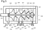
- the centrifugal compressor 500 compresses a refrigerant gas from a suction pressure at the main inlet 519 to a discharge pressure at the main outlet 520.
- the compressor 500 is configured to compress the refrigerant gas with a ratio between said discharge and suction pressures higher than 10, preferably higher than 12, more preferably higher than 15.
- the term "high compression ratio" means a ratio between the outlet and inlet pressures as described hereabove.
- the compression ratio required by the C3MR and Cascade processes is considered as a high compression ratio, especially when it is performed by a single compressor compressing a light gas refrigerant.
- the compressor 500 is thus configured to compress refrigerant gases having molecular weight less than 30 g/mol.
- the terms "light refrigerant/s”, “light gas/es”, “low molecular weight gases” refer to all refrigerant gases, thus all gases used in refrigeration processes, having molecular weight less than 30 g/mol.
- the compressor 500 is a centrifugal compressor and, in order to compress light refrigerants with high compression ratio, it can comprise two or three, even four, sections of compression.
- Each section of compression can comprise one or more compression stages.
- Each compression stage can comprise a centrifugal impeller, a diffuser and a return channel.
- the diffuser and/or the return channel are part of the stationary part of the compressor and can include vanes. All impellers are connected together to form the rotor.
- Part of the rotor can be the shaft 531.
- the shaft 531 can be firmly connected to the rotor.
- the shaft 531 is mechanically connected to the driver machine (not shown in Fig.5 ).
- Each section of compression has its own inlet and outlet. Therefore, the compressor can comprise two or more inlets, one main inlet and one or more auxiliary inlets, and two or more outlets, one main outlet and one or more auxiliary outlets.
- a compressor 500 having two section of compressions 523, 524 arranged in series.
- the first section of compression comprises an inlet 519 and an outlet 521 and two compression stages 525, 526, each one comprising an impeller 507, 508.
- the second section of compression comprises an inlet 522 and an outlet 520 and three compression stages 527, 528, 529, each one comprising one impeller 509, 510, 511.
- the refrigerant gas enters through the main inlet 519 (arrow 502), is compressed by the first section of compression 523 and exits from the auxiliary outlet 521 (arrow 504). After an intercooling step, the compressed and cooled refrigerant gas enters again in the compressor, through the auxiliary inlet 522. The refrigerant gas is then compressed in the second section of compression 524 and exits definitively through the main outlet 520.
- Each section of compression is configured to compress the refrigerant gas under certain conditions, for example from a specific inlet pressure to a specific outlet pressure between an intercooling stage.
- auxiliary inlet/s and/or auxiliary outlet/s enable the compressor to be more flexible and to adapt the operative conditions of the machine to the process where the compressor is used.
- the auxiliary inlet/s and auxiliary outlet/s may be used to extract working fluid from the compressor and refrigerate it before being reinjected
- the ethylene compressor thus the first single compressor 409 of the first compression train 402, comprises two inlet streams like those of compressor 500 of Fig. 5 .
- the refrigerant gas is intercooled (intercooling not shown).
- Each section of compression resembles, from a compression point of view, to an independent compressor like those labeled 310 and 311 in the Fig. 3 .
- One important technical difference is that all sections of compression are arranged in a common compressor machine having a single casing.
- All sections of compression 523, 524 of the centrifugal compressor 500 are arranged in a common bundle 501 which is configured to be removably insertable in a single common casing 530.
- the rotor and stationary parts are assembled together in a cylindrical bundle that, like a cartridge, is configured to be reversibly axially inserted through one end of the casing 530 in the casing 530 itself.
- the opposite side of the compressor with respect to the driver machine is normally free of obstacles, and consequently the extraction of the bundle for maintenance activities is facilitated.
- the outlet of a section of compression is directly or indirectly fluidly coupled to the inlet of the section of compression arranged downstream.
- All sections of compression are arranged to compress the same type of refrigerant gas.
- the outlet 521 of the first section of compression 523 is fluidly connected to inlet 522 of the more downstream section of compression, thus the second section of compression 524.
- the inlet and outlet of subsequent sections of compression can be fluidly connected through an intercooling section, wherein the refrigerant gas, compressed by a more upstream section, is cooled before re-entry in the subsequent section.
- the sections of compression are three instead of two.
- the third section is arranged downstream the second section, which in turn is arranged downstream the first section, and the outlet of the first section is directly or indirectly fluidly connected to the inlet of the second section of compression and the outlet of the second section is directly or indirectly fluidly connected to the inlet of the third section.
- At least one section of compression can be arranged back-to-back.
- the outlet of two neighbor sections are arranged next to each other.
- Neighbor sections of compression can be separated by means of labyrinth or abradable seals in order to limit leakages from one section to the other.
- the axial length of these seals can be comprised between 30% and 40%, preferably about 35%, of the average diameter of impellers of said neighbor sections of compression. This range of value guarantees that leakages are highly reduced.
- the rotor of the compressor 500 comprises a plurality of impellers, arranged in a plurality of sections of compression as previously described, and the impellers have constant or decreasing diameters, while the last impeller is always smaller than the first one.
- the first impeller 507 can have a diameter equal to that of the second impeller 508, which in turn has a diameter larger than that of the third impeller 509; while the third, fourth and fifth impellers 509, 510, 511 have diameters which progressively decrease.
- All the impellers can be stacked one on the other to form the rotor.
- a common tie rod 506 can be arranged and configured to maintain all the impellers 507, 508, 509, 510, 511 grouped together. A mutual slippage of neighbor impellers is avoided by means of Hirth connections 512, 513, 514, 515. Opposite axial ends of the impellers comprise Hirth joints. The stacked and coupled impellers are tightened together by means of the tie rod. In this way, a very stable and reliable mechanical connection is achieved.
- the tie rod can be axially pre-loaded in order to compress the impellers.
- Each impeller 507, 508, 509, 510, 511 can have a passing hole at its rotational axis and can be configured so that the tie rod can pass through it.
- the impellers of the centrifugal compressor of the present invention are configured to have a peripheral Mach number smaller than 1,1, preferably smaller than 1, thus subsonic.
- the velocity of sound (C) varies inversely with the square root of the molecular weight of the fluid. Therefore, lower molecular weight refrigerants give rise to high sonic velocities.
- the present centrifugal compressor is configured to process in a single casing low molecular weight gases, like mixed refrigerant of C3MR process, or ethylene and methane of Cascade process: mixed refrigerant of C3MR has a molecule weight of about 26 gr/mol, ethylene has a molecular weight of 28 gr/mol and methane has a molecular weight of 16 gr/mol.
- the present compressor is configured to rotate to a high rotational speed, preferably between 3.600 and 8.000 rpm, being the molecular weight of the processed refrigerant gas lower than 30 g/mol.
- At least one of the impeller of the centrifugal compressor has a peripheral speed over 300 m/s, preferably over 380 m/s.
- the most upstream impeller/s can be of the open type, that means without shroud.
- the other impellers thus those arranged downstream the first group of open impeller/s, can comprise shrouds 516, 517, 518.
- the most upstream impeller/s have high peripheral speed/s with respect to the other impellers and consequently larger diameter/s. For this reason, the most upstream impellers can be unshrouded for avoiding mechanical stresses.
- the average diameter of first two impellers can be higher than 1,2 times of the average diameter of the other impellers. Unshrouded impellers can rotate faster than shrouded impellers, due to the absence of the shroud; in fact, when the impeller rotates the shroud is pull outwardly by the centrifugal force acting on it and over a certain rotary speed the shroud risks to pull out the impeller.
- the impeller can rotate faster than traditional centrifugal compressors thus achieving a greater compression ratio.
- the portion of the casing arranged around the inlet and/or outlet mouth/s has a greater thickness with respect to the average thickness of the rest of the casing, in order to strengthen the casing of the compressor in the zone of the compressor widely stressed by the high pressure.
- the driver machine of the compression train can be a single-shaft gas turbine, a multi-shaft gas turbine, or a steam turbine.
- the driver machine can be variable-speed drive (VSD) electric motor, or a fixed-speed electric motor.
- VSD variable-speed drive
- the compression train so provided doesn't required any further compressor connected directly/indirectly to the driver machine.
Landscapes
- Engineering & Computer Science (AREA)
- Mechanical Engineering (AREA)
- General Engineering & Computer Science (AREA)
- Physics & Mathematics (AREA)
- Thermal Sciences (AREA)
- Chemical & Material Sciences (AREA)
- Chemical Kinetics & Catalysis (AREA)
- General Chemical & Material Sciences (AREA)
- Oil, Petroleum & Natural Gas (AREA)
- Structures Of Non-Positive Displacement Pumps (AREA)
- Separation By Low-Temperature Treatments (AREA)
Abstract
Description
- Embodiments of the subject matter disclosed herein correspond to compression trains including a single centrifugal compressor and LNG (= Liquefied Natural Gas) plants including said compression train.
- In the field of "Oil & Gas", i.e. machines and plants for exploration, production, storage, refinement and distribution of oil and/or gas, there is always a search for improved solutions.
- Improvements may derive from e.g. the structure and/or operation of the machines, the connection of machines, or the combination of machines (for example trains of machines).
- Improvements may consist in e.g. increased efficiency and/or reduced losses, increased production and/or decreased wastes, increased functions, reduced cost, reduced size and/or footprint.
- Several liquefaction processes for large LNG plants are known in the art:
- AP-C3MR® designed by Air Products & Chemicals, Inc. (APCI);
- Cascade designed by ConocoPhillips;
- AP-X® designed by Air Products & Chemicals, Inc. (APCI);
- DMR (=Dual Mixed Refrigerant) of Shell;
- SMR (Single Mixed Refrigerant);
- MFC® (mixed fluid cascade) designed by Linde;
- PRICO® (SMR) designed by Black & Veatch;
- Liquefin® designed by Air Liquide.
- These known processes are already optimized in term of process but improvements, in particular in terms of number of machines and/or footprint of machines used in an LNG plant are, still sought.
- The AP-C3MR® (also called "C3MR") process uses a pure-refrigerant ("C3"), i.e. propane, and a mixed refrigerant ("MR"), i.e. a mixture of typically propane, ethylene, and methane; this process is a 2-cycles liquefaction technology: (one) pure-refrigerant and (one) mixed-refrigerant.
-
Fig. 1 shows a schematic view of LNG plant according to a AP-C3MR® (hereinafter called simply "C3MR") designed by Air Products & Chemicals. The C3MR is a widely diffused LNG process. The C3MR process consists of two refrigeration cycles: a propane-refrigeration (C3) cycle to cool the natural gas, and mixed refrigerant (MR) cycle to liquefy the natural gas stream. - In the propane refrigeration cycle, the propane is compressed in a
single compressor 106 which is driven by adriver 105. - The compressed propane is cooled in a
cooler 111 and then, via theline 113, it passes through theexchanger 107 to absorb heat from the natural gas and mixed refrigerant streams. Before theexchanger 107, an expansion of the compressed propane occurs. - In the mixed refrigerant cycle, the mixed refrigerant is compressed through a
compression train 100 comprising threecompressors driver 104. Sometime, thedriver 105 of the propane cycle, can be configured to drive one of the three compressors of the mixed refrigerant cycle. - The compressed mixed refrigerant is cooled in a
cooler 110 and then, via theline 114, passes through theexchanger 107 wherein it is pre-cooled. Before theexchanger 107, an expansion of the compressed propane occurs. - The low pressure, warm main liquefaction mixed refrigerant can be sent to a sequence of
inter-cooled compressors compressor 103, cooled inintercooler 115, further compressed in thecompressor 102, cooled inintercooler 109, further compressed incompressor 101, and then further cooled inaftercooler 110 to emerge as a high pressure fluid. - The cooled high pressure mixed refrigerant stream can be pre-cooled using
heat exchanger 107 resulting in pre-cooled stream. Pre-cooled stream may be separated into lighter refrigerant and heavier refrigerant streams inseparator 112. The lighter refrigerant stream may then be condensed and sub-cooled in themain liquefaction exchanger 108. The heavier refrigerant liquid stream may also be sub-cooled in themain liquefaction exchanger 108. - The pre-cooled stream of natural gas is then sent to the cryogenic section of the plant, thus to the
main liquefaction exchanger 108, to fully condense and sub-cool vapor stream forming LNG product stream. - The Cascade designed by ConocoPhillips (hereinafter called simply "Cascade") process uses three pure-refrigerants, i.e. typically propane, ethylene or ethane, and methane; this process is a 3-cycles (three) pure-refrigerants liquefaction technology.
- It is to be noted that the expression "pure refrigerant" actually means that one substance is predominant (for example, at least 90% or 95% or 98%) in the refrigerant; the substance may be a chemical compound (for example, propane, ethane, ethylene, methane).
-
Fig. 3 shows a schematic view of LNG plant according to a Cascade process. The Cascade process is, like C3MR, widely diffused. - The Cascade process consists of three refrigeration cycles: a propane refrigeration cycle to pre-cool the natural gas stream, an ethylene refrigeration cycle to cool the pre-cooled natural gas stream, and a methane refrigeration cycle to liquefy the cooled natural gas stream.
- In the propane refrigeration cycle, the propane is compressed by means of a
compression train 303 comprising twocompressors driver 306 configured to drive the compressors. - The compressed propane is cooled in a
cooler 316 and then it passes through theexchanger 317 to absorb heat from the natural gas, ethylene and methane streams. Before theexchanger 317, an expansion of the compressed propane occurs. - In the ethylene refrigeration cycle, the ethylene is compressed by means of a
compression train 302 comprising twocompressors driver 305 configured to drive the compressors. - The compressed ethylene is cooled in a
cooler 315 and in theheat exchanger 317. Then it passes through theexchanger 318 to absorb heat from the natural gas and methane streams. Before theexchanger 318, an expansion of the compressed ethylene occurs. - The
heat exchanger 318 may be also used to cool vapors of natural gas separated inseparator 320 from the heavier components of the natural gas. The heavier components form natural gas liquefied, which is different from liquefied natural gas. - In the methane refrigeration cycle, the methane is compressed by means of a
compression train 301 comprising threecompressors driver 304 configured to drive the compressors. - The compressed methane is cooled in a
cooler 314 and in theheat exchangers exchanger 319 to form liquefied natural gas. Before theexchanger 319, an expansion of the compressed methane occurs. - In the field of compressors, it's generally known that compression ratio is proportional to the molecular weight of the process gas under the same boundary conditions.
- More the gas is lighter and more is difficult to compress it in a single casing, and several compressors are required to achieve high compression ratio. This problem occurs both in C3MR and Cascade processes with mixed refrigerant, ethylene and methane respectively.
- In the state of the art it is not known a compression train having machines able to compress light gases with high compression ratio in medium-large scale LNG plants.
- In particular, it is still sought a machine able to compress light refrigerant gases at high compression ratio in a single casing, thus using a single compressor instead of two or more.
- In the LNG it is generally known to compress light gases, like mixed refrigerant, ethylene, or methane through two or more compressor machines, due to the low molecular weight of these gases. Consequently, LNG compression train are generally not compact when the processed gas has a small molecular weight.
- The above identified drawbacks of the prior art are now overcome by the first and second scope of the present invention relating to a compression train and a LNG plant.
- The compression train for a natural gas liquefaction process can comprise a driver machine and only one centrifugal compressor machine driven in rotation by said driver machine. The compressor can be configured to compress a refrigerant gas with a molecular weight less than 30 g/mol from a suction pressure to a discharge pressure. The ratio between discharge and suction pressures can be higher than 10, preferably higher than 12, more preferably higher than 15.
- The LNG plant can comprise one or more compression trains according to the present invention.
- Features and embodiments are disclosed here below and are further set forth in the appended claims, which form an integral part of the present description. The above brief description sets forth features of the various embodiments of the present invention in order that the detailed description that follows may be better understood and in order that the present contributions to the art may be better appreciated. There are, of course, other features of the invention that will be described hereinafter and which will be set forth in the appended claims. In this respect, before explaining several embodiments of the invention in details, it is understood that the various embodiments of the invention are not limited in their application to the details of the construction and to the arrangements of the components set forth in the following description or illustrated in the drawings. The invention is capable of other embodiments and of being practiced and carried out in various ways. Also, it is to be understood that the phraseology and terminology employed herein are for the purpose of description and should not be regarded as limiting.
- As such, those skilled in the art will appreciate that the conception, upon which the disclosure is based, may readily be utilized as a basis for designing other structures, methods, and/or systems for carrying out the several purposes of the present invention. It is important, therefore, that the claims be regarded as including such equivalent constructions insofar as they do not depart from the spirit and scope of the present invention.
- A more complete appreciation of the disclosed embodiments of the invention and many of the attendant advantages thereof will be readily obtained as the same becomes better understood by reference to the following detailed description when considered in connection with the accompanying drawings, wherein:
-
Fig. 1 shows a schematic diagram of a prior art LNG plant according to AP-C3MR® process; -
Fig. 2 shows a schematic diagram of a LNG plant according to a first embodiment of the present invention; -
Fig. 3 shows a schematic diagram of a prior art LNG plant according to Cascade process; -
Fig. 4 shows a schematic diagram of a LNG plant according to a second embodiment of the present invention; -
Fig. 5 shows a schematic view of a high compression ratio compressor according to the present invention. - The following description of exemplary embodiments refers to the accompanying drawings.
- The following description does not limit the invention. Instead, the scope of the invention is defined by the appended claims.
- Reference throughout the specification to "one embodiment" or "an embodiment" means that a particular feature, structure, or characteristic described in connection with an embodiment is included in at least one embodiment of the subject matter disclosed. Thus, the appearance of the phrases "in one embodiment" or "in an embodiment" in various places throughout the specification is not necessarily referring to the same embodiment. Further, the particular features, structures or characteristics may be combined in any suitable manner in one or more embodiments.
- In the following (and according to its mathematical meaning) the term "set" means a group of one or more items.
- With reference to
Fig. 2 , it is shown a LNG plant according to the C3MR process, as previously described, comprising a first embodiment of compression train. - In the propane refrigeration cycle, the propane is compressed in a
single compressor 206 which is driven by adriver 205.Driver 205 can be an electrical motor or a gas turbine. - The compressed propane is cooled in a cooler 211 and then, via the
line 213, it passes through theexchanger 207 to absorb heat from the natural gas and mixed refrigerant streams. Before theexchanger 207, an expansion of the compressed propane occurs, preferably with a Joule-Thomson valve (not shown). - In the mixed refrigerant cycle, the mixed refrigerant is compressed by means of a
compression train 200 comprising asingle compressor 201 and adriver machine 204.Driver machine 204 can be an electrical motor or a gas turbine. - The
driver machine 204 can be directly coupled to thesingle compressor 201. - In a particular embodiment, the
compression train 200 can also comprise a gearbox (not shown), arranged between thedriver machine 204 and thesingle compressor 201, configured to increase the rotational speed ofdriver machine 204. The gearbox can comprise an input shaft mechanically coupled to thedriver machine 204 and an output shaft mechanically coupled to thesingle compressor 201, specifically to the compressor shaft. - After the compression in the
single compressor 201, the compressed mixed refrigerant is cooled in a cooler 210 and then, via theline 214, it passes through theexchanger 207, wherein it is pre-cooled. Before theexchanger 207, an expansion of the compressed propane occurs, preferably with a Joule-Thomson valve (not shown). - The
single compressor 201 can be inter-cooled throughintercoolers - In order to obtain the required compression ratio requested by the C3MR process, a specific type of single compressor is used, as will be more clearly understood when the following description is read.
- The cooled high pressure mixed refrigerant stream is then pre-cooled using
heat exchanger 207 resulting in a pre-cooled stream. Pre-cooled stream may be separated into lighter refrigerant stream and heavier refrigerant streams inseparator 212. The lighter refrigerant may then be condensed and sub-cooled in themain liquefaction exchanger 208. The heavier refrigerant liquid stream may also be sub-cooled in themain liquefaction exchanger 208. - The pre-cooled stream of natural gas is then sent to the cryogenic section of the plant, thus to the
main liquefaction exchanger 208, to fully condense and sub-cool vapor stream, and to form LNG product stream. - According to the well-known SplitMR® arrangement designed by Air Products & Chemicals Inc., the compression train of the propane can comprise one of the three compressors of the mixed refrigerant. In a preferred embodiment, a revamping method of an existing SplitMR® LNG plant is provided, wherein the mixed refrigerant is compressed by means of a compression train according to the present invention, and the compression train of the propane can comprise a driver, a compressor configured to compress the propane and an electric generator configured to convert in electric power the available extra power produced by the driver.
- With reference to
Fig. 4 , it is shown a LNG plant according to Cascade process, as previously described, comprising compression trains according to further embodiments of the present invention. - In the propane refrigeration cycle, the propane is compressed by means of a
compression train 403 comprising twocompressors driver 406 configured to drive the compressors.Driver 406 can be an electrical motor or a gas turbine. - The compressed propane is cooled in a cooler 414 and then it passes through the
first exchanger 415 to absorb heat from the natural gas, ethylene and methane streams. Before theexchanger 415, an expansion of the compressed propane occurs, preferably with a Joule-Thomson valve (not shown). - In the ethylene refrigeration cycle, the ethylene is compressed by means of a
first compression train 402 comprising a firstsingle compressor 409 and afirst driver machine 405 configured to drive in rotation thesingle compressor 409.Driver machine 405 can be an electrical motor or a gas turbine. - The
driver machine 405 is directly-connected to thefirst compressor 409 through a direct connection. The direct connection can be of type flexible or rigid, depending on the specific operating context. - The compressed ethylene is cooled in a cooler 413 and in the
first heat exchanger 415. Then, the ethylene stream passes through thesecond heat exchanger 416 to absorb heat from the natural gas and methane streams. Before thesecond heat exchanger 416, an expansion of the compressed ethylene occurs, preferably with a Joule-Thomson valve (not shown). - The
second heat exchanger 416 may be also used to cool vapors of natural gas separated from the heavier components of the natural gas inseparator 418. The heavier components form natural gas liquefied. - In the methane refrigeration cycle, the methane is compressed by means of a
second compression train 401 comprising a secondsingle compressor 408 and asecond driver machine 404 configured to drive in rotation the secondsingle compressor 408.Second driver machine 404 can be an electrical motor or a gas turbine. - The
second driver machine 404 and the secondsingle compressor 408 are mechanically connected through agearbox 407 configured to increase the rotation speed of thesecond driver machine 404. Thegearbox 407 can comprise an input shaft mechanically coupled to thesecond driver machine 404 and an output shaft mechanically coupled to the shaft of the secondsingle compressor 408. - The compressed methane is cooled in a cooler 412 and in the first and
second heat exchangers third heat exchanger 417 to absorb heat from the cooled natural gas. The stream of natural gas is thus fully condensed and a LNG product stream is achieved. Before theexchanger 417, an expansion of the compressed methane occurs. - With reference to the first and second embodiments, the compressor of said
compression train 200,first compression train 402 andsecond compression train 401, can be of type described hereinafter. - With further reference to
Fig. 5 , thecentrifugal compressor 500 compresses a refrigerant gas from a suction pressure at themain inlet 519 to a discharge pressure at themain outlet 520. Thecompressor 500 is configured to compress the refrigerant gas with a ratio between said discharge and suction pressures higher than 10, preferably higher than 12, more preferably higher than 15. In the present invention, the term "high compression ratio" means a ratio between the outlet and inlet pressures as described hereabove. - The compression ratio required by the C3MR and Cascade processes is considered as a high compression ratio, especially when it is performed by a single compressor compressing a light gas refrigerant.
- The
compressor 500 is thus configured to compress refrigerant gases having molecular weight less than 30 g/mol. - In the present invention, the terms "light refrigerant/s", "light gas/es", "low molecular weight gases" refer to all refrigerant gases, thus all gases used in refrigeration processes, having molecular weight less than 30 g/mol.
- The
compressor 500 is a centrifugal compressor and, in order to compress light refrigerants with high compression ratio, it can comprise two or three, even four, sections of compression. Each section of compression can comprise one or more compression stages. Each compression stage can comprise a centrifugal impeller, a diffuser and a return channel. The diffuser and/or the return channel are part of the stationary part of the compressor and can include vanes. All impellers are connected together to form the rotor. - Part of the rotor can be the
shaft 531. Alternatively, theshaft 531 can be firmly connected to the rotor. Theshaft 531 is mechanically connected to the driver machine (not shown inFig.5 ). - Each section of compression has its own inlet and outlet. Therefore, the compressor can comprise two or more inlets, one main inlet and one or more auxiliary inlets, and two or more outlets, one main outlet and one or more auxiliary outlets. With reference to
Fig. 5 , it's shown acompressor 500 having two section ofcompressions inlet 519 and anoutlet 521 and twocompression stages impeller inlet 522 and anoutlet 520 and threecompression stages impeller compression 523 and exits from the auxiliary outlet 521 (arrow 504). After an intercooling step, the compressed and cooled refrigerant gas enters again in the compressor, through theauxiliary inlet 522. The refrigerant gas is then compressed in the second section ofcompression 524 and exits definitively through themain outlet 520. - Each section of compression is configured to compress the refrigerant gas under certain conditions, for example from a specific inlet pressure to a specific outlet pressure between an intercooling stage.
- The auxiliary inlet/s and/or auxiliary outlet/s enable the compressor to be more flexible and to adapt the operative conditions of the machine to the process where the compressor is used. For example, the auxiliary inlet/s and auxiliary outlet/s may be used to extract working fluid from the compressor and refrigerate it before being reinjected
- For example, with reference to
Fig. 4 , the ethylene compressor, thus the firstsingle compressor 409 of thefirst compression train 402, comprises two inlet streams like those ofcompressor 500 ofFig. 5 . Between theoutlet 504 of the first section of compression and theinlet 503 of the second section of compression, the refrigerant gas is intercooled (intercooling not shown). - Each section of compression resembles, from a compression point of view, to an independent compressor like those labeled 310 and 311 in the
Fig. 3 . One important technical difference is that all sections of compression are arranged in a common compressor machine having a single casing. - All sections of
compression centrifugal compressor 500 are arranged in acommon bundle 501 which is configured to be removably insertable in a singlecommon casing 530. The rotor and stationary parts are assembled together in a cylindrical bundle that, like a cartridge, is configured to be reversibly axially inserted through one end of thecasing 530 in thecasing 530 itself. The opposite side of the compressor with respect to the driver machine is normally free of obstacles, and consequently the extraction of the bundle for maintenance activities is facilitated. - The outlet of a section of compression is directly or indirectly fluidly coupled to the inlet of the section of compression arranged downstream.
- All sections of compression are arranged to compress the same type of refrigerant gas.
- If the sections of compression are two, like in the compressor of
Fig. 5 , theoutlet 521 of the first section ofcompression 523 is fluidly connected toinlet 522 of the more downstream section of compression, thus the second section ofcompression 524. - The inlet and outlet of subsequent sections of compression can be fluidly connected through an intercooling section, wherein the refrigerant gas, compressed by a more upstream section, is cooled before re-entry in the subsequent section.
- The same concept applies when the sections of compression are three instead of two. Thus, when the third section is arranged downstream the second section, which in turn is arranged downstream the first section, and the outlet of the first section is directly or indirectly fluidly connected to the inlet of the second section of compression and the outlet of the second section is directly or indirectly fluidly connected to the inlet of the third section.
- At least one section of compression can be arranged back-to-back. In this case, the outlet of two neighbor sections are arranged next to each other.
- Neighbor sections of compression can be separated by means of labyrinth or abradable seals in order to limit leakages from one section to the other.
- In particular, the axial length of these seals can be comprised between 30% and 40%, preferably about 35%, of the average diameter of impellers of said neighbor sections of compression. This range of value guarantees that leakages are highly reduced.
- The rotor of the
compressor 500 comprises a plurality of impellers, arranged in a plurality of sections of compression as previously described, and the impellers have constant or decreasing diameters, while the last impeller is always smaller than the first one. For example, thefirst impeller 507 can have a diameter equal to that of thesecond impeller 508, which in turn has a diameter larger than that of thethird impeller 509; while the third, fourth andfifth impellers - All the impellers can be stacked one on the other to form the rotor. A
common tie rod 506 can be arranged and configured to maintain all theimpellers Hirth connections impeller - The impellers of the centrifugal compressor of the present invention are configured to have a peripheral Mach number smaller than 1,1, preferably smaller than 1, thus subsonic.
- The Mach number (Ma) is normally calculated by the following formula:


- The velocity of sound (C) varies inversely with the square root of the molecular weight of the fluid. Therefore, lower molecular weight refrigerants give rise to high sonic velocities.
- The present centrifugal compressor is configured to process in a single casing low molecular weight gases, like mixed refrigerant of C3MR process, or ethylene and methane of Cascade process: mixed refrigerant of C3MR has a molecule weight of about 26 gr/mol, ethylene has a molecular weight of 28 gr/mol and methane has a molecular weight of 16 gr/mol.
- The present compressor is configured to rotate to a high rotational speed, preferably between 3.600 and 8.000 rpm, being the molecular weight of the processed refrigerant gas lower than 30 g/mol. These features allow to maintain the impellers in sub-sonic operating conditions.
- At least one of the impeller of the centrifugal compressor has a peripheral speed over 300 m/s, preferably over 380 m/s.
- Preferably, the most upstream impeller/s can be of the open type, that means without shroud. On the contrary the other impellers, thus those arranged downstream the first group of open impeller/s, can comprise
shrouds 516, 517, 518. - The most upstream impeller/s have high peripheral speed/s with respect to the other impellers and consequently larger diameter/s. For this reason, the most upstream impellers can be unshrouded for avoiding mechanical stresses. The average diameter of first two impellers can be higher than 1,2 times of the average diameter of the other impellers. Unshrouded impellers can rotate faster than shrouded impellers, due to the absence of the shroud; in fact, when the impeller rotates the shroud is pull outwardly by the centrifugal force acting on it and over a certain rotary speed the shroud risks to pull out the impeller.
- Thanks to the rotor configuration of the compressor defined above, the impeller can rotate faster than traditional centrifugal compressors thus achieving a greater compression ratio.
- In one embodiment, the portion of the casing arranged around the inlet and/or outlet mouth/s has a greater thickness with respect to the average thickness of the rest of the casing, in order to strengthen the casing of the compressor in the zone of the compressor widely stressed by the high pressure.
- The driver machine of the compression train according to any embodiment of the present invention can be a single-shaft gas turbine, a multi-shaft gas turbine, or a steam turbine. In a further preferred embodiment, the driver machine can be variable-speed drive (VSD) electric motor, or a fixed-speed electric motor.
- Due to technical features of the present centrifugal compressor, the couple of traditional
centrifugal compressors single compressor 409 as previously described. - Due to the same reasons, the three traditional
centrifugal compressors single compressor 408 as previously described. - Furthermore, for the same disclosed technical reasons, the three traditional
centrifugal compressors single compressor 201 as previously described. - The compression previously performed by more than one compressors can now be performed with a single compressor according to the present invention without compromising the overall performances. Evident advantages are so achieved.
- The compression train so provided doesn't required any further compressor connected directly/indirectly to the driver machine.
- By using compression train/s with compressor/s according to the present invention, a higher LNG production may be obtained in a smaller space and/or in a smaller footprint and with a lesser number of machines.
- It is to be noted that having only one case instead of two or more cases is advantageous from many points of view:
- it simplifies installation and maintenance,
- it reduces maintenance time,
- it increases reliability (less components and less likelihood of failure),
- it reduces footprint and weight of machines,
- it reduces leakages of gases,
- it reduces the complexity and size of the lubricant oil system.
- Even if the present compression train has been adapted and described for C3MR and Cascade processes, it can be easily adapted and used for other LNG processes.
- While the disclosed embodiments of the subject matter described herein have been shown in the drawings and fully described above with particularity and detail in connection with several exemplary embodiments, it will be apparent to those of ordinary skill in the art that many modifications, changes, and omissions are possible with-out materially departing from the novel teachings, the principles and concepts set forth herein, and advantages of the subject matter recited in the appended claims. Hence, the proper scope of the disclosed innovations should be determined only by the broadest interpretation of the appended claims so as to encompass all such modifications, changes, and omissions. In addition, the order or sequence of any process or method steps may be varied or re-sequenced according to alternative embodiments.
- Various aspects and embodiments of the present invention are defined by the following numbered clauses:
- 1. A compression train comprising an engine and a high speed compressor driven by the engine; wherein the high speed compressor is a centrifugal compressor and comprises a first set of impellers and a second set of impellers arranged downstream or upstream the first set of impellers; the impellers of the first set being centrifugal and unshrouded; the impellers of the second set being centrifugal and shrouded; at least the impellers of the first set and of the second set being housed inside one common casing; the impellers of the first set and of the second set being coupled to each other through mechanical connections.
- 2. The compression train of clause 1, wherein the engine is an electric motor or a steam turbine or a gas turbine, in particular an aeroderivative gas turbine.
- 3. The compression train of clause 1 or 2, wherein the engine and the high speed compressor are connected directly or through a gear box.
- 4. The compression train of clause 1, 2 or 3, comprising a further centrifugal compressor arranged between the engine and the high speed compressor.
- 5. The compression train of clause 4 depending on clause 2, wherein the gear box is arranged between the high speed compressor and the further compressor.
- 6. The compression train of any of preceding clause, wherein the compression train comprises a helper motor configured to help the main engine when the power absorbed by the compressor/s exceeds a predetermined threshold.
- 7. Compression train for a natural gas liquefaction process comprising:
- a driver machine;
- only one centrifugal compressor machine driven in rotation by said driver machine;
- the compressor being configured to compress a refrigerant gas with a molecular weight less than 30 g/mol from a suction pressure to a discharge pressure;
- wherein the ratio between discharge and suction pressures is higher than 10, preferably higher than 12, more preferably higher than 15.
- 8. Compression train according to any preceding clause, wherein the driver machine and the compressor machine are mechanically direct-connected each other.
- 9. Compression train according to any preceding clause, wherein the driver machine and the compressor machine are connected each other by means of a gear-box.
- 10. Compression train according to any preceding clause, wherein the compressor machine comprises a plurality of stages of compression split in two or three sections of compression.
- 11. Compression train according to any preceding clause, wherein the compressor machine is of barrel-type and the two or more sections of compression are arranged in a common bundle removably insertable in a common casing.
- 12. Compression train according to any preceding clause, wherein the compressor machine comprises an inlet and an outlet for each section of compression.
- 13. Compression train according to any preceding clause, wherein the sections of compression are two, the second section is arranged downstream the first one, and the outlet of the first section is directly or indirectly fluidly connected to the inlet of the second section.
- 14. Compression train according to any preceding clause, wherein the sections of compression are three, the third section is arranged downstream the second one which in turn is arranged downstream the first one, the outlet of the first section is directly or indirectly fluidly connected to the inlet of the second section of compression, and the outlet of the second section is directly or indirectly fluidly connected to the inlet of the third section of compression.
- 15. Compression train according to any preceding clause, wherein the driver machine is single-shaft gas turbine or a multi-shaft gas turbine or an electric motor.
- 16. Compression train according to any preceding clause, wherein the refrigerant gas is mixed refrigerant and the natural gas liquefaction process is of the type AP-C3MR®.
- 17. Compression train according to any preceding clause, wherein the refrigerant is ethylene or methane and the natural gas liquefaction process is of the type Cascade.
- 18. Compression train according to any preceding clause, wherein the gas refrigerant passes through an intercooler between an outlet and the subsequent inlet.
- 19. Compression train according to any preceding clause, wherein each stage of compression comprises an impeller and wherein impellers have constant or decreasing diameters and the last impeller has a smaller diameter with respect to the first one.
- 20. Compression train according to any preceding clause, wherein the most upstream impeller/s is/are open-type impeller/s and the other impellers are closed-type impellers.
- 21. Compression train according to any preceding clause, wherein the impellers are stacked one on the other to form a rotor.
- 22. Compression train according to any preceding clause, wherein the peripheral Mach number of the impellers is smaller than 1,1, preferably smaller than 1.
- 23. Compression train according to any preceding clause, wherein at least one impeller has a peripheral speed over 300 m/s, preferably over 380 m/s.
- 24. Compression train according to any preceding clause, wherein between neighbor sections of compression a labyrinth or abradable seal is provided, and wherein the axial length of the seal is between 30% and 40%, preferably about 35%, of the average diameter of impellers of said neighbor sections of compression.
- 25. Compression train according to any preceding clause, wherein compressor casing has a greater thickness around the compressor inlet and/or outlet mouth/s, with respect to the average thickness of the rest of casing.
- 26. LNG plant comprising one or more compression train according to one or more of preceding claims.
Claims (15)
- Compression train for a natural gas liquefaction process comprising:a driver machine;only one centrifugal compressor machine driven in rotation by said driver machine;the compressor being configured to compress a refrigerant gas with a molecular weight less than 30 g/mol from a suction pressure to a discharge pressure;wherein the ratio between discharge and suction pressures is higher than 10, preferably higher than 12, more preferably higher than 15.
- Compression train according to claim 1, wherein the driver machine and the compressor machine are mechanically direct-connected each other.
- Compression train according to claim 1, wherein the driver machine and the compressor machine are connected each other by means of a gear-box.
- Compression train according to claim 1, wherein the compressor machine comprises a plurality of stages of compression split in two or three sections of compression.
- Compression train according to claim 4, wherein the compressor machine is of barrel-type and the two or more sections of compression are arranged in a common bundle removably insertable in a common casing.
- Compression train according to claim 4 or 5, wherein the compressor machine comprises an inlet and an outlet for each section of compression.
- Compression train according to claim 6, wherein the sections of compression are two, the second section is arranged downstream the first one, and the outlet of the first section is directly or indirectly fluidly connected to the inlet of the second section.
- Compression train according to claim 6, wherein the sections of compression are three, the third section is arranged downstream the second one which in turn is arranged downstream the first one, the outlet of the first section is directly or indirectly fluidly connected to the inlet of the second section of compression, and the outlet of the second section is directly or indirectly fluidly connected to the inlet of the third section of compression.
- Compression train according to any of preceding claims, wherein the driver machine is single-shaft gas turbine or a multi-shaft gas turbine or an electric motor.
- Compression train according to any of preceding claims, wherein the refrigerant gas is mixed refrigerant and the natural gas liquefaction process is of the type AP-C3MR®.
- Compression train according to any of preceding claims, wherein the refrigerant is ethylene or methane and the natural gas liquefaction process is of the type Cascade.
- Compression train according to claim 7 or 8, wherein the gas refrigerant passes through an intercooler between an outlet and the subsequent inlet.
- Compression train according to claim 5, wherein each stage of compression comprises an impeller and wherein impellers have constant or decreasing diameters and the last impeller has a smaller diameter with respect to the first one.
- Compression train according to claim 13, wherein the most upstream impeller/s is/are open-type impeller/s and the other impellers are closed-type impellers.
- LNG plant comprising one or more compression train according to one or more of preceding claims.
Applications Claiming Priority (1)
| Application Number | Priority Date | Filing Date | Title |
|---|---|---|---|
| IT102017000007473A IT201700007473A1 (en) | 2017-01-24 | 2017-01-24 | COMPRESSION TRAIN WITH A CENTRIFUGAL COMPRESSOR AND LNG PLANT |
Publications (2)
| Publication Number | Publication Date |
|---|---|
| EP3351882A1 true EP3351882A1 (en) | 2018-07-25 |
| EP3351882B1 EP3351882B1 (en) | 2024-05-01 |
Family
ID=58701818
Family Applications (1)
| Application Number | Title | Priority Date | Filing Date |
|---|---|---|---|
| EP18152558.5A Active EP3351882B1 (en) | 2017-01-24 | 2018-01-19 | Compression train including one centrifugal compressor and lng plant |
Country Status (6)
| Country | Link |
|---|---|
| US (1) | US10809000B2 (en) |
| EP (1) | EP3351882B1 (en) |
| JP (2) | JP2018150930A (en) |
| KR (1) | KR102502369B1 (en) |
| CN (1) | CN108458548A (en) |
| IT (1) | IT201700007473A1 (en) |
Cited By (1)
| Publication number | Priority date | Publication date | Assignee | Title |
|---|---|---|---|---|
| EP3812593A1 (en) * | 2019-10-24 | 2021-04-28 | Mitsubishi Heavy Industries Compressor Corporation | Centrifugal compressor |
Families Citing this family (12)
| Publication number | Priority date | Publication date | Assignee | Title |
|---|---|---|---|---|
| FR3086373B1 (en) * | 2018-09-20 | 2020-12-11 | Air Liquide | INSTALLATION AND PROCEDURE FOR CLEANING AND LIQUEFACING NATURAL GAS |
| WO2020075295A1 (en) * | 2018-10-12 | 2020-04-16 | 日揮グローバル株式会社 | Natural gas liquefaction device |
| IT201800011099A1 (en) * | 2018-12-14 | 2020-06-14 | Nuovo Pignone Tecnologie Srl | PROPANE DE-HYDROGENATION SYSTEM WITH A SINGLE BOX REACTOR EFFLUENT COMPRESSOR AND METHOD |
| JP7313459B2 (en) * | 2019-10-09 | 2023-07-24 | 日揮グローバル株式会社 | natural gas liquefier |
| JP7341854B2 (en) * | 2019-10-25 | 2023-09-11 | 三菱重工コンプレッサ株式会社 | Charge gas compressor train for ethylene plant |
| JP7333247B2 (en) * | 2019-11-01 | 2023-08-24 | 三菱重工コンプレッサ株式会社 | Ammonia plant synthesis gas compressor train |
| US11911732B2 (en) | 2020-04-03 | 2024-02-27 | Nublu Innovations, Llc | Oilfield deep well processing and injection facility and methods |
| CN116249863A (en) * | 2020-08-12 | 2023-06-09 | 克里奥斯塔股份有限公司 | Simple Low Temperature Refrigeration System |
| US20220252340A1 (en) * | 2021-02-05 | 2022-08-11 | High Roller E & C, LLC | Systems and processes for stationary and mobile natural gas liquefaction |
| IT202400001557A1 (en) * | 2024-01-26 | 2025-07-26 | Nuovo Pignone Tecnologie Srl | NATURAL GAS COOLING SYSTEM WITH A MIXED REFRIGERANT |
| WO2025212239A1 (en) * | 2024-04-05 | 2025-10-09 | Danfoss A/S | Impeller and shaft position sensor configurations for refrigerant compressor |
| WO2026027551A1 (en) | 2024-08-01 | 2026-02-05 | Nuovo Pignone Tecnologie - S.R.L. | Multistage turboexpander |
Citations (3)
| Publication number | Priority date | Publication date | Assignee | Title |
|---|---|---|---|---|
| DE102007029882A1 (en) * | 2007-06-28 | 2009-01-02 | Linde Ag | Process for cooling or liquefying a hydrocarbon-rich stream |
| FR2920529A1 (en) * | 2007-09-04 | 2009-03-06 | Total Sa | Cooling unit i.e. natural gas liquefaction unit, starting method, involves injecting cleaning gas in circuit, and injecting filling gases in circuit, where average molar mass of one filling gas is higher than that of another filling gas |
| US20150152884A1 (en) * | 2012-06-06 | 2015-06-04 | Nuovo Pignone Srl | High pressure ratio compressors with multiple intercooling and related methods |
Family Cites Families (27)
| Publication number | Priority date | Publication date | Assignee | Title |
|---|---|---|---|---|
| US3162519A (en) * | 1958-06-30 | 1964-12-22 | Conch Int Methane Ltd | Liquefaction of natural gas |
| GB1464558A (en) * | 1973-04-13 | 1977-02-16 | Cryoplants Ltd | Gas liquefaction process and apparatus |
| US4057371A (en) * | 1974-05-03 | 1977-11-08 | Norwalk-Turbo Inc. | Gas turbine driven high speed centrifugal compressor unit |
| JPS6034593U (en) * | 1984-07-09 | 1985-03-09 | 川崎重工業株式会社 | Multi-stage turbo compressor |
| JPS6392098U (en) * | 1986-12-05 | 1988-06-14 | ||
| US5087172A (en) * | 1989-02-13 | 1992-02-11 | Dresser-Rand Company, A General Partnership | Compressor cartridge seal method |
| JP3168865B2 (en) * | 1995-03-20 | 2001-05-21 | 株式会社日立製作所 | Impeller for multistage centrifugal compressor and method of manufacturing the same |
| JPH0953593A (en) * | 1995-08-09 | 1997-02-25 | Hitachi Ltd | Shaft sealing device for rotary fluid machinery |
| CN1117217C (en) * | 1998-03-13 | 2003-08-06 | 株式会社日立制作所 | Centrifugal compressor and shaft seal used thereof |
| US7310971B2 (en) * | 2004-10-25 | 2007-12-25 | Conocophillips Company | LNG system employing optimized heat exchangers to provide liquid reflux stream |
| IT1317651B1 (en) * | 2000-05-19 | 2003-07-15 | Nuovo Pignone Spa | CASE FOR CENTRIFUGAL COMPRESSORS AND PROCEDURE FOR SUAREALIZATION |
| US7937945B2 (en) * | 2006-10-27 | 2011-05-10 | Kinde Sr Ronald August | Combining a series of more efficient engines into a unit, or modular units |
| WO2009073838A1 (en) * | 2007-12-07 | 2009-06-11 | Dresser-Rand Company | Compressor system and method for gas liquefaction system |
| IT1400370B1 (en) * | 2010-05-31 | 2013-05-31 | Nuova Pignone S R L | METHOD AND DEVICE FOR RECOVERING NATURAL LIQUEFIED NGL GAS |
| JP5524109B2 (en) * | 2011-02-25 | 2014-06-18 | 三菱重工コンプレッサ株式会社 | Compressor |
| ITCO20120069A1 (en) * | 2012-12-27 | 2014-06-28 | Nuovo Pignone Srl | STATHICAL COMPRESSOR ASSEMBLY OF LARGE SIZE |
| US10087950B2 (en) * | 2013-01-28 | 2018-10-02 | Mitsubishi Heavy Industries Compressor Corporation | Centrifugal rotation machine |
| CN203239633U (en) * | 2013-03-29 | 2013-10-16 | 中国石油天然气股份有限公司 | The casing structure of the two-stage cylindrical centrifugal compressor |
| JP6124659B2 (en) * | 2013-04-15 | 2017-05-10 | 株式会社日立製作所 | Multistage centrifugal fluid machine |
| ITCO20130069A1 (en) | 2013-12-18 | 2015-06-19 | Nuovo Pignone Srl | MULTI-STAGE CENTRIFUGAL COMPRESSOR |
| JP6184018B2 (en) * | 2014-02-06 | 2017-08-23 | 三菱重工業株式会社 | Intermediate suction diaphragm and centrifugal rotating machine |
| US10473109B2 (en) * | 2014-03-03 | 2019-11-12 | Nuovo Pignone Srl | Method and system for operating a back-to-back compressor with a side stream |
| CN106574626A (en) * | 2014-09-18 | 2017-04-19 | 三菱重工压缩机有限公司 | Compressor system |
| US9759480B2 (en) * | 2014-10-10 | 2017-09-12 | Air Products And Chemicals, Inc. | Refrigerant recovery in natural gas liquefaction processes |
| US10584709B2 (en) * | 2015-03-27 | 2020-03-10 | Dresser-Rand Company | Electrically heated balance piston seal |
| US10208768B2 (en) * | 2015-03-27 | 2019-02-19 | Dresser-Rand Company | Heat shield for pressure casing |
| WO2017129518A1 (en) * | 2016-01-25 | 2017-08-03 | Nuovo Pignone Tecnologie Srl | Compressor train start-up using variable inlet guide vanes |
-
2017
- 2017-01-24 IT IT102017000007473A patent/IT201700007473A1/en unknown
-
2018
- 2018-01-05 US US15/862,879 patent/US10809000B2/en active Active
- 2018-01-12 JP JP2018003031A patent/JP2018150930A/en active Pending
- 2018-01-19 EP EP18152558.5A patent/EP3351882B1/en active Active
- 2018-01-23 KR KR1020180008332A patent/KR102502369B1/en active Active
- 2018-01-24 CN CN201810068765.7A patent/CN108458548A/en active Pending
-
2022
- 2022-10-14 JP JP2022165357A patent/JP7431302B2/en active Active
Patent Citations (3)
| Publication number | Priority date | Publication date | Assignee | Title |
|---|---|---|---|---|
| DE102007029882A1 (en) * | 2007-06-28 | 2009-01-02 | Linde Ag | Process for cooling or liquefying a hydrocarbon-rich stream |
| FR2920529A1 (en) * | 2007-09-04 | 2009-03-06 | Total Sa | Cooling unit i.e. natural gas liquefaction unit, starting method, involves injecting cleaning gas in circuit, and injecting filling gases in circuit, where average molar mass of one filling gas is higher than that of another filling gas |
| US20150152884A1 (en) * | 2012-06-06 | 2015-06-04 | Nuovo Pignone Srl | High pressure ratio compressors with multiple intercooling and related methods |
Non-Patent Citations (2)
| Title |
|---|
| HENRI PARADOWSKI ET AL: "PROPANE PRECOOLING CYCLES FOR INCREASED LNG TRAIN CAPACITY", vol. 14TH, 1 March 2006 (2006-03-01), pages PS2 - 3/1, XP009108061, Retrieved from the Internet <URL:http://www.kgu.or.kr/admin/data/P-000/PS2-3-Paradowski.pdf> * |
| PILLARELLA M ET AL: "THE C3MR LIQUEFACTION CYCLE: VERSATILITY FOR A FAST GROWING, EVER CHANGING LNG INDUSTRY", vol. 15TH, 24 May 2007 (2007-05-24), pages PS2 - 5/1, XP009108435, Retrieved from the Internet <URL:http://www.kgu.or.kr/admin/data/P-000/e24dba96efa969ae9c9e056d2dffb446.pdf> * |
Cited By (2)
| Publication number | Priority date | Publication date | Assignee | Title |
|---|---|---|---|---|
| EP3812593A1 (en) * | 2019-10-24 | 2021-04-28 | Mitsubishi Heavy Industries Compressor Corporation | Centrifugal compressor |
| US11221016B2 (en) | 2019-10-24 | 2022-01-11 | Mitsubishi Heavy Industries Compressor Corporation | Centrifugal compressor |
Also Published As
| Publication number | Publication date |
|---|---|
| KR102502369B1 (en) | 2023-02-21 |
| US10809000B2 (en) | 2020-10-20 |
| JP2022191411A (en) | 2022-12-27 |
| EP3351882B1 (en) | 2024-05-01 |
| US20180209728A1 (en) | 2018-07-26 |
| KR20180087185A (en) | 2018-08-01 |
| BR102018001358A2 (en) | 2018-12-04 |
| CN108458548A (en) | 2018-08-28 |
| IT201700007473A1 (en) | 2018-07-24 |
| JP7431302B2 (en) | 2024-02-14 |
| JP2018150930A (en) | 2018-09-27 |
Similar Documents
| Publication | Publication Date | Title |
|---|---|---|
| US10809000B2 (en) | Compression train including one centrifugal compressor and LNG plant | |
| US6484533B1 (en) | Method and apparatus for the production of a liquid cryogen | |
| AU2011256697B2 (en) | Parallel dynamic compressor apparatus and methods related thereto | |
| US10480852B2 (en) | System and method for liquefaction of natural gas | |
| CN108692523B (en) | Parallel compression in LNG plants using dual flow compressors | |
| WO2011026960A1 (en) | Method of operating a gas turbine and gas turbine | |
| US20160040927A1 (en) | Integrally-geared compressors for precooling in lng applications | |
| CN105579686A (en) | Systems and methods of utilizing axial flow expanders | |
| AU2009316236B2 (en) | Power matched mixed refrigerant compression circuit | |
| EP3532786B1 (en) | Natural gas liquefaction system including an integrally-geared turbo-compressor | |
| US20180209427A1 (en) | Lng plant including an axial compressor and a centrifugal compressor | |
| BR102018001358B1 (en) | COMPRESSION UNIT AND LNG PLANT | |
| US11268753B2 (en) | Split refrigerant compressor for the liquefaction of natural gas |
Legal Events
| Date | Code | Title | Description |
|---|---|---|---|
| PUAI | Public reference made under article 153(3) epc to a published international application that has entered the european phase |
Free format text: ORIGINAL CODE: 0009012 |
|
| STAA | Information on the status of an ep patent application or granted ep patent |
Free format text: STATUS: THE APPLICATION HAS BEEN PUBLISHED |
|
| AK | Designated contracting states |
Kind code of ref document: A1 Designated state(s): AL AT BE BG CH CY CZ DE DK EE ES FI FR GB GR HR HU IE IS IT LI LT LU LV MC MK MT NL NO PL PT RO RS SE SI SK SM TR |
|
| AX | Request for extension of the european patent |
Extension state: BA ME |
|
| STAA | Information on the status of an ep patent application or granted ep patent |
Free format text: STATUS: REQUEST FOR EXAMINATION WAS MADE |
|
| 17P | Request for examination filed |
Effective date: 20190125 |
|
| RBV | Designated contracting states (corrected) |
Designated state(s): AL AT BE BG CH CY CZ DE DK EE ES FI FR GB GR HR HU IE IS IT LI LT LU LV MC MK MT NL NO PL PT RO RS SE SI SK SM TR |
|
| STAA | Information on the status of an ep patent application or granted ep patent |
Free format text: STATUS: EXAMINATION IS IN PROGRESS |
|
| 17Q | First examination report despatched |
Effective date: 20200513 |
|
| P01 | Opt-out of the competence of the unified patent court (upc) registered |
Effective date: 20230526 |
|
| GRAP | Despatch of communication of intention to grant a patent |
Free format text: ORIGINAL CODE: EPIDOSNIGR1 |
|
| STAA | Information on the status of an ep patent application or granted ep patent |
Free format text: STATUS: GRANT OF PATENT IS INTENDED |
|
| INTG | Intention to grant announced |
Effective date: 20240221 |
|
| GRAS | Grant fee paid |
Free format text: ORIGINAL CODE: EPIDOSNIGR3 |
|
| GRAA | (expected) grant |
Free format text: ORIGINAL CODE: 0009210 |
|
| STAA | Information on the status of an ep patent application or granted ep patent |
Free format text: STATUS: THE PATENT HAS BEEN GRANTED |
|
| RAP3 | Party data changed (applicant data changed or rights of an application transferred) |
Owner name: NUOVO PIGNONE TECNOLOGIE - S.R.L. |
|
| AK | Designated contracting states |
Kind code of ref document: B1 Designated state(s): AL AT BE BG CH CY CZ DE DK EE ES FI FR GB GR HR HU IE IS IT LI LT LU LV MC MK MT NL NO PL PT RO RS SE SI SK SM TR |
|
| REG | Reference to a national code |
Ref country code: GB Ref legal event code: FG4D |
|
| REG | Reference to a national code |
Ref country code: CH Ref legal event code: EP |
|
| REG | Reference to a national code |
Ref country code: DE Ref legal event code: R096 Ref document number: 602018068779 Country of ref document: DE |
|
| REG | Reference to a national code |
Ref country code: IE Ref legal event code: FG4D |
|
| REG | Reference to a national code |
Ref country code: LT Ref legal event code: MG9D |
|
| REG | Reference to a national code |
Ref country code: NL Ref legal event code: MP Effective date: 20240501 |
|
| PG25 | Lapsed in a contracting state [announced via postgrant information from national office to epo] |
Ref country code: IS Free format text: LAPSE BECAUSE OF FAILURE TO SUBMIT A TRANSLATION OF THE DESCRIPTION OR TO PAY THE FEE WITHIN THE PRESCRIBED TIME-LIMIT Effective date: 20240901 |
|
| PG25 | Lapsed in a contracting state [announced via postgrant information from national office to epo] |
Ref country code: BG Free format text: LAPSE BECAUSE OF FAILURE TO SUBMIT A TRANSLATION OF THE DESCRIPTION OR TO PAY THE FEE WITHIN THE PRESCRIBED TIME-LIMIT Effective date: 20240501 |
|
| PG25 | Lapsed in a contracting state [announced via postgrant information from national office to epo] |
Ref country code: FI Free format text: LAPSE BECAUSE OF FAILURE TO SUBMIT A TRANSLATION OF THE DESCRIPTION OR TO PAY THE FEE WITHIN THE PRESCRIBED TIME-LIMIT Effective date: 20240501 Ref country code: HR Free format text: LAPSE BECAUSE OF FAILURE TO SUBMIT A TRANSLATION OF THE DESCRIPTION OR TO PAY THE FEE WITHIN THE PRESCRIBED TIME-LIMIT Effective date: 20240501 |
|
| PG25 | Lapsed in a contracting state [announced via postgrant information from national office to epo] |
Ref country code: GR Free format text: LAPSE BECAUSE OF FAILURE TO SUBMIT A TRANSLATION OF THE DESCRIPTION OR TO PAY THE FEE WITHIN THE PRESCRIBED TIME-LIMIT Effective date: 20240802 |
|
| PG25 | Lapsed in a contracting state [announced via postgrant information from national office to epo] |
Ref country code: PT Free format text: LAPSE BECAUSE OF FAILURE TO SUBMIT A TRANSLATION OF THE DESCRIPTION OR TO PAY THE FEE WITHIN THE PRESCRIBED TIME-LIMIT Effective date: 20240902 |
|
| REG | Reference to a national code |
Ref country code: AT Ref legal event code: MK05 Ref document number: 1682859 Country of ref document: AT Kind code of ref document: T Effective date: 20240501 |
|
| PG25 | Lapsed in a contracting state [announced via postgrant information from national office to epo] |
Ref country code: NL Free format text: LAPSE BECAUSE OF FAILURE TO SUBMIT A TRANSLATION OF THE DESCRIPTION OR TO PAY THE FEE WITHIN THE PRESCRIBED TIME-LIMIT Effective date: 20240501 |
|
| PG25 | Lapsed in a contracting state [announced via postgrant information from national office to epo] |
Ref country code: ES Free format text: LAPSE BECAUSE OF FAILURE TO SUBMIT A TRANSLATION OF THE DESCRIPTION OR TO PAY THE FEE WITHIN THE PRESCRIBED TIME-LIMIT Effective date: 20240501 |
|
| PG25 | Lapsed in a contracting state [announced via postgrant information from national office to epo] |
Ref country code: AT Free format text: LAPSE BECAUSE OF FAILURE TO SUBMIT A TRANSLATION OF THE DESCRIPTION OR TO PAY THE FEE WITHIN THE PRESCRIBED TIME-LIMIT Effective date: 20240501 |
|
| PG25 | Lapsed in a contracting state [announced via postgrant information from national office to epo] |
Ref country code: PL Free format text: LAPSE BECAUSE OF FAILURE TO SUBMIT A TRANSLATION OF THE DESCRIPTION OR TO PAY THE FEE WITHIN THE PRESCRIBED TIME-LIMIT Effective date: 20240501 |
|
| PG25 | Lapsed in a contracting state [announced via postgrant information from national office to epo] |
Ref country code: LV Free format text: LAPSE BECAUSE OF FAILURE TO SUBMIT A TRANSLATION OF THE DESCRIPTION OR TO PAY THE FEE WITHIN THE PRESCRIBED TIME-LIMIT Effective date: 20240501 |
|
| PG25 | Lapsed in a contracting state [announced via postgrant information from national office to epo] |
Ref country code: PT Free format text: LAPSE BECAUSE OF FAILURE TO SUBMIT A TRANSLATION OF THE DESCRIPTION OR TO PAY THE FEE WITHIN THE PRESCRIBED TIME-LIMIT Effective date: 20240902 Ref country code: PL Free format text: LAPSE BECAUSE OF FAILURE TO SUBMIT A TRANSLATION OF THE DESCRIPTION OR TO PAY THE FEE WITHIN THE PRESCRIBED TIME-LIMIT Effective date: 20240501 Ref country code: NO Free format text: LAPSE BECAUSE OF FAILURE TO SUBMIT A TRANSLATION OF THE DESCRIPTION OR TO PAY THE FEE WITHIN THE PRESCRIBED TIME-LIMIT Effective date: 20240801 Ref country code: NL Free format text: LAPSE BECAUSE OF FAILURE TO SUBMIT A TRANSLATION OF THE DESCRIPTION OR TO PAY THE FEE WITHIN THE PRESCRIBED TIME-LIMIT Effective date: 20240501 Ref country code: LV Free format text: LAPSE BECAUSE OF FAILURE TO SUBMIT A TRANSLATION OF THE DESCRIPTION OR TO PAY THE FEE WITHIN THE PRESCRIBED TIME-LIMIT Effective date: 20240501 Ref country code: IS Free format text: LAPSE BECAUSE OF FAILURE TO SUBMIT A TRANSLATION OF THE DESCRIPTION OR TO PAY THE FEE WITHIN THE PRESCRIBED TIME-LIMIT Effective date: 20240901 Ref country code: HR Free format text: LAPSE BECAUSE OF FAILURE TO SUBMIT A TRANSLATION OF THE DESCRIPTION OR TO PAY THE FEE WITHIN THE PRESCRIBED TIME-LIMIT Effective date: 20240501 Ref country code: GR Free format text: LAPSE BECAUSE OF FAILURE TO SUBMIT A TRANSLATION OF THE DESCRIPTION OR TO PAY THE FEE WITHIN THE PRESCRIBED TIME-LIMIT Effective date: 20240802 Ref country code: FI Free format text: LAPSE BECAUSE OF FAILURE TO SUBMIT A TRANSLATION OF THE DESCRIPTION OR TO PAY THE FEE WITHIN THE PRESCRIBED TIME-LIMIT Effective date: 20240501 Ref country code: ES Free format text: LAPSE BECAUSE OF FAILURE TO SUBMIT A TRANSLATION OF THE DESCRIPTION OR TO PAY THE FEE WITHIN THE PRESCRIBED TIME-LIMIT Effective date: 20240501 Ref country code: BG Free format text: LAPSE BECAUSE OF FAILURE TO SUBMIT A TRANSLATION OF THE DESCRIPTION OR TO PAY THE FEE WITHIN THE PRESCRIBED TIME-LIMIT Effective date: 20240501 Ref country code: AT Free format text: LAPSE BECAUSE OF FAILURE TO SUBMIT A TRANSLATION OF THE DESCRIPTION OR TO PAY THE FEE WITHIN THE PRESCRIBED TIME-LIMIT Effective date: 20240501 Ref country code: RS Free format text: LAPSE BECAUSE OF FAILURE TO SUBMIT A TRANSLATION OF THE DESCRIPTION OR TO PAY THE FEE WITHIN THE PRESCRIBED TIME-LIMIT Effective date: 20240801 |
|
| PG25 | Lapsed in a contracting state [announced via postgrant information from national office to epo] |
Ref country code: DK Free format text: LAPSE BECAUSE OF FAILURE TO SUBMIT A TRANSLATION OF THE DESCRIPTION OR TO PAY THE FEE WITHIN THE PRESCRIBED TIME-LIMIT Effective date: 20240501 |
|
| PG25 | Lapsed in a contracting state [announced via postgrant information from national office to epo] |
Ref country code: EE Free format text: LAPSE BECAUSE OF FAILURE TO SUBMIT A TRANSLATION OF THE DESCRIPTION OR TO PAY THE FEE WITHIN THE PRESCRIBED TIME-LIMIT Effective date: 20240501 |
|
| PG25 | Lapsed in a contracting state [announced via postgrant information from national office to epo] |
Ref country code: CZ Free format text: LAPSE BECAUSE OF FAILURE TO SUBMIT A TRANSLATION OF THE DESCRIPTION OR TO PAY THE FEE WITHIN THE PRESCRIBED TIME-LIMIT Effective date: 20240501 |
|
| PG25 | Lapsed in a contracting state [announced via postgrant information from national office to epo] |
Ref country code: RO Free format text: LAPSE BECAUSE OF FAILURE TO SUBMIT A TRANSLATION OF THE DESCRIPTION OR TO PAY THE FEE WITHIN THE PRESCRIBED TIME-LIMIT Effective date: 20240501 Ref country code: SK Free format text: LAPSE BECAUSE OF FAILURE TO SUBMIT A TRANSLATION OF THE DESCRIPTION OR TO PAY THE FEE WITHIN THE PRESCRIBED TIME-LIMIT Effective date: 20240501 |
|
| PG25 | Lapsed in a contracting state [announced via postgrant information from national office to epo] |
Ref country code: SM Free format text: LAPSE BECAUSE OF FAILURE TO SUBMIT A TRANSLATION OF THE DESCRIPTION OR TO PAY THE FEE WITHIN THE PRESCRIBED TIME-LIMIT Effective date: 20240501 |
|
| PG25 | Lapsed in a contracting state [announced via postgrant information from national office to epo] |
Ref country code: SM Free format text: LAPSE BECAUSE OF FAILURE TO SUBMIT A TRANSLATION OF THE DESCRIPTION OR TO PAY THE FEE WITHIN THE PRESCRIBED TIME-LIMIT Effective date: 20240501 Ref country code: SK Free format text: LAPSE BECAUSE OF FAILURE TO SUBMIT A TRANSLATION OF THE DESCRIPTION OR TO PAY THE FEE WITHIN THE PRESCRIBED TIME-LIMIT Effective date: 20240501 Ref country code: RO Free format text: LAPSE BECAUSE OF FAILURE TO SUBMIT A TRANSLATION OF THE DESCRIPTION OR TO PAY THE FEE WITHIN THE PRESCRIBED TIME-LIMIT Effective date: 20240501 Ref country code: EE Free format text: LAPSE BECAUSE OF FAILURE TO SUBMIT A TRANSLATION OF THE DESCRIPTION OR TO PAY THE FEE WITHIN THE PRESCRIBED TIME-LIMIT Effective date: 20240501 Ref country code: DK Free format text: LAPSE BECAUSE OF FAILURE TO SUBMIT A TRANSLATION OF THE DESCRIPTION OR TO PAY THE FEE WITHIN THE PRESCRIBED TIME-LIMIT Effective date: 20240501 Ref country code: CZ Free format text: LAPSE BECAUSE OF FAILURE TO SUBMIT A TRANSLATION OF THE DESCRIPTION OR TO PAY THE FEE WITHIN THE PRESCRIBED TIME-LIMIT Effective date: 20240501 |
|
| REG | Reference to a national code |
Ref country code: DE Ref legal event code: R097 Ref document number: 602018068779 Country of ref document: DE |
|
| PG25 | Lapsed in a contracting state [announced via postgrant information from national office to epo] |
Ref country code: IT Free format text: LAPSE BECAUSE OF FAILURE TO SUBMIT A TRANSLATION OF THE DESCRIPTION OR TO PAY THE FEE WITHIN THE PRESCRIBED TIME-LIMIT Effective date: 20240501 |
|
| PLBE | No opposition filed within time limit |
Free format text: ORIGINAL CODE: 0009261 |
|
| STAA | Information on the status of an ep patent application or granted ep patent |
Free format text: STATUS: NO OPPOSITION FILED WITHIN TIME LIMIT |
|
| 26N | No opposition filed |
Effective date: 20250204 |
|
| PG25 | Lapsed in a contracting state [announced via postgrant information from national office to epo] |
Ref country code: SI Free format text: LAPSE BECAUSE OF FAILURE TO SUBMIT A TRANSLATION OF THE DESCRIPTION OR TO PAY THE FEE WITHIN THE PRESCRIBED TIME-LIMIT Effective date: 20240501 |
|
| REG | Reference to a national code |
Ref country code: CH Ref legal event code: PL |
|
| PG25 | Lapsed in a contracting state [announced via postgrant information from national office to epo] |
Ref country code: SE Free format text: LAPSE BECAUSE OF FAILURE TO SUBMIT A TRANSLATION OF THE DESCRIPTION OR TO PAY THE FEE WITHIN THE PRESCRIBED TIME-LIMIT Effective date: 20240501 |
|
| PG25 | Lapsed in a contracting state [announced via postgrant information from national office to epo] |
Ref country code: MC Free format text: LAPSE BECAUSE OF FAILURE TO SUBMIT A TRANSLATION OF THE DESCRIPTION OR TO PAY THE FEE WITHIN THE PRESCRIBED TIME-LIMIT Effective date: 20240501 Ref country code: LU Free format text: LAPSE BECAUSE OF NON-PAYMENT OF DUE FEES Effective date: 20250119 |
|
| PG25 | Lapsed in a contracting state [announced via postgrant information from national office to epo] |
Ref country code: BE Free format text: LAPSE BECAUSE OF NON-PAYMENT OF DUE FEES Effective date: 20250131 |
|
| PG25 | Lapsed in a contracting state [announced via postgrant information from national office to epo] |
Ref country code: CH Free format text: LAPSE BECAUSE OF NON-PAYMENT OF DUE FEES Effective date: 20250131 |
|
| REG | Reference to a national code |
Ref country code: BE Ref legal event code: MM Effective date: 20250131 |
|
| PGFP | Annual fee paid to national office [announced via postgrant information from national office to epo] |
Ref country code: GB Payment date: 20251219 Year of fee payment: 9 |
|
| PGFP | Annual fee paid to national office [announced via postgrant information from national office to epo] |
Ref country code: FR Payment date: 20251217 Year of fee payment: 9 |
|
| PG25 | Lapsed in a contracting state [announced via postgrant information from national office to epo] |
Ref country code: IE Free format text: LAPSE BECAUSE OF NON-PAYMENT OF DUE FEES Effective date: 20250119 |
|
| PGFP | Annual fee paid to national office [announced via postgrant information from national office to epo] |
Ref country code: DE Payment date: 20251217 Year of fee payment: 9 |