EP3351805A1 - Ejector and vacuum generation device with same - Google Patents
Ejector and vacuum generation device with same Download PDFInfo
- Publication number
- EP3351805A1 EP3351805A1 EP16846258.8A EP16846258A EP3351805A1 EP 3351805 A1 EP3351805 A1 EP 3351805A1 EP 16846258 A EP16846258 A EP 16846258A EP 3351805 A1 EP3351805 A1 EP 3351805A1
- Authority
- EP
- European Patent Office
- Prior art keywords
- fluid
- ejector
- diffuser
- tank
- nozzle
- Prior art date
- Legal status (The legal status is an assumption and is not a legal conclusion. Google has not performed a legal analysis and makes no representation as to the accuracy of the status listed.)
- Granted
Links
Images

Classifications
-
- F—MECHANICAL ENGINEERING; LIGHTING; HEATING; WEAPONS; BLASTING
- F04—POSITIVE - DISPLACEMENT MACHINES FOR LIQUIDS; PUMPS FOR LIQUIDS OR ELASTIC FLUIDS
- F04F—PUMPING OF FLUID BY DIRECT CONTACT OF ANOTHER FLUID OR BY USING INERTIA OF FLUID TO BE PUMPED; SIPHONS
- F04F5/00—Jet pumps, i.e. devices in which flow is induced by pressure drop caused by velocity of another fluid flow
- F04F5/02—Jet pumps, i.e. devices in which flow is induced by pressure drop caused by velocity of another fluid flow the inducing fluid being liquid
- F04F5/04—Jet pumps, i.e. devices in which flow is induced by pressure drop caused by velocity of another fluid flow the inducing fluid being liquid displacing elastic fluids
-
- F—MECHANICAL ENGINEERING; LIGHTING; HEATING; WEAPONS; BLASTING
- F04—POSITIVE - DISPLACEMENT MACHINES FOR LIQUIDS; PUMPS FOR LIQUIDS OR ELASTIC FLUIDS
- F04F—PUMPING OF FLUID BY DIRECT CONTACT OF ANOTHER FLUID OR BY USING INERTIA OF FLUID TO BE PUMPED; SIPHONS
- F04F5/00—Jet pumps, i.e. devices in which flow is induced by pressure drop caused by velocity of another fluid flow
- F04F5/02—Jet pumps, i.e. devices in which flow is induced by pressure drop caused by velocity of another fluid flow the inducing fluid being liquid
- F04F5/10—Jet pumps, i.e. devices in which flow is induced by pressure drop caused by velocity of another fluid flow the inducing fluid being liquid displacing liquids, e.g. containing solids, or liquids and elastic fluids
-
- F—MECHANICAL ENGINEERING; LIGHTING; HEATING; WEAPONS; BLASTING
- F04—POSITIVE - DISPLACEMENT MACHINES FOR LIQUIDS; PUMPS FOR LIQUIDS OR ELASTIC FLUIDS
- F04F—PUMPING OF FLUID BY DIRECT CONTACT OF ANOTHER FLUID OR BY USING INERTIA OF FLUID TO BE PUMPED; SIPHONS
- F04F5/00—Jet pumps, i.e. devices in which flow is induced by pressure drop caused by velocity of another fluid flow
- F04F5/44—Component parts, details, or accessories not provided for in, or of interest apart from, groups F04F5/02 - F04F5/42
Definitions
- the disclosure relates to an ejector and a vacuum generation device including the ejector.
- a vacuum generation device described in Patent Literature 1 circulates a fluid stored in a tank through a pump and an ejector as a first fluid to allow the ejector to generate a suction force, which sucks a second fluid.
- Patent Literature 1 Japanese Unexamined Patent Application Publication No. 2014-156814
- the ejector includes a nozzle and a diffuser that are designed to suck the second fluid as intended.
- the ejector including the nozzle and the diffuser designed as above may fail to suck the second fluid as intended if the ejector malfunctions.
- the ejector may malfunction when, for example, the pressure of the fluid passing through the diffuser is not raised sufficiently.
- one or more aspects of the disclosure are directed to an ejector that functions properly.
- An ejector includes a nozzle that ejects a first fluid, a suction chamber that sucks a second fluid using a pressure decrease caused by ejection of the first fluid through the nozzle, a diffuser that discharges the first fluid ejected through the nozzle and the second fluid sucked into the suction chamber while raising a pressure of the first fluid and the second fluid, and at least one flow restrictor located downstream from the diffuser.
- a vacuum generation device includes the ejector, a tank that stores the first fluid and the second fluid that have passed through the diffuser, and a pump connected to the tank.
- the pump pumps a fluid in the tank to the ejector as the first fluid.
- the pump and the ejector allow the fluid in the tank to circulate through them and suck the second fluid through the ejector.
- the ejector according to the above aspect includes the flow restrictor located downstream from the diffuser to sufficiently raise the pressure of the fluid passing through the diffuser. The ejector can thus function properly.
- the vacuum generation device includes the flow restrictor located downstream from the diffuser to sufficiently raise the pressure of the fluid passing through the diffuser.
- the ejector can thus function properly.
- the vacuum generation device can suck the second fluid properly.
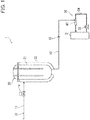
- FIG. 1 is a schematic diagram of piping for a vacuum steam heating system 1 according to one embodiment.
- the vacuum steam heating system (hereafter, the heating system) 1 includes a reaction tank 20, which heats an object with steam, a steam supply pipe 11, which supplies steam to the reaction tank 20 from a steam generator (not shown), a discharge pipe 13, which discharges a drain generated in the reaction tank 20, and a vacuum generation device 30, which sucks the drain through the discharge pipe 13.
- the heating system 1 includes a fluid circuit 10, which includes the steam supply pipe 11, the reaction tank 20, the discharge pipe 13, and the vacuum generation device 30. The heating system 1 heats an object placed in the reaction tank 20 with saturated steam at an atmospheric pressure or less.
- the reaction tank 20 includes a tank body 21, in which an object is placed, and a jacket 22, which extends along substantially the entire periphery of the tank body 21.
- the steam supply pipe 11 is connected to the jacket 22.
- the steam supply pipe 11 includes a supply valve 14, which is an on-off valve. Steam generated in the steam generator is supplied to the jacket 22 through the steam supply pipe 11.
- the steam supplied to the jacket 22 indirectly exchanges heat with the object placed in the tank body 21 in the reaction tank 20 to condense (or liquefy) and heat the object in the tank body 21. More specifically, the object is heated with the condensed latent heat from the steam.
- the discharge pipe 13 has one end (inlet end) connected to a lower end part of the jacket 22, and the other end (outlet end) connected to the vacuum generation device 30.
- the discharge pipe 13 discharges the drain (condensate) generated from the steam condensed in the jacket 22.
- the discharge pipe 13 includes a steam trap 15, which automatically discharges only the drain flowing into the steam trap 15.
- the vacuum generation device 30 includes a drain tank 31, which stores the drain, a pump 32, which pumps the drain in the drain tank 31, and an ejector 40, which sucks the drain from the reaction tank 20 through the discharge pipe 13.
- the drain tank 31, the pump 32, and the ejector 40 are connected to one another with a pipe 34. This forms a circulation passage including the drain tank 31, the pump 32, and the ejector 40.
- the vacuum generation device 30 circulates the drain stored in the drain tank 31 through the pump 32 and the ejector 40 to cause the ejector 40 to generate a suction force, which then sucks the drain from the reaction tank 20.
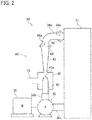
- FIG. 2 is a schematic diagram of the vacuum generation device 30.
- the pipe 34 includes a first pipe 34a connecting the drain tank 31 and the pump 32, a second pipe 34b connecting the pump 32 and the ejector 40, and a third pipe 34c connecting the ejector 40 and the drain tank 31.
- the drain tank 31 is an example of the tank.
- the pump 32 is driven by a motor 35.
- the ejector 40 includes a nozzle 41 for ejecting a first fluid, a suction chamber 42, which uses a negative pressure generated by the first fluid ejected through the nozzle 41 to suck a second fluid, a diffuser 43, which discharges the first fluid ejected through the nozzle 41 and the second fluid sucked into the suction chamber 42 while raising their pressure, and two orifice plates 44 located downstream from the diffuser 43.
- the nozzle 41 is connected to a downstream end of the second pipe 34b.
- the nozzle 41 has an injection hole 41a located at least inside the suction chamber 42.
- the suction chamber 42 also contains at least an upstream end part of the diffuser 43.
- the discharge pipe 13 has the outlet end connected into the suction chamber 42.
- the second fluid is sucked from the discharge pipe 13 under a negative pressure (pressure decrease) caused by ejection of the first fluid through the nozzle 41.
- the negative pressure resulting from the jet pumping of the first fluid generates a suction force for sucking the second fluid.
- the orifice plates 44 are disc-shaped, and each have a circular central opening 44a.
- the orifice plates 44 are an example of a flow restrictor.
- the orifice plates 44 are located inside the third pipe 34c. More specifically, the upstream orifice plate 44 is located on an upstream end of the third pipe 34c, or is located at a joint between the diffuser 43 and the third pipe 34c.
- the downstream orifice plate 44 is located on a downstream end of the third pipe 34c, or is located at a joint between the third pipe 34c and the drain tank 31.
- the diffuser 43 and the third pipe 34c are connected to each other at their flanges.
- the upstream orifice plate 44 is located between the flange of the diffuser 43 and the flange of the third pipe 34c.
- the third pipe 34c and the drain tank 31 are connected to each other at their flanges.
- the downstream orifice plate 44 is located between the flange of the third pipe 34c and the flange of the
- the opening 44a in the upstream orifice plate 44 has an area smaller than the cross-sectional area of a passage in the part of the third pipe 34c downstream from the orifice plate 44.
- the opening 44a in the downstream orifice plate 44 has an area smaller than the cross-sectional area of a passage in the part of the third pipe 34c upstream from the orifice plate 44.
- the upstream and downstream orifice plates 44 function as chokes to narrow the cross-sectional area of the passage downstream from the diffuser 43.
- the opening 44a in the upstream orifice plate 44 has the same area as the opening 44a in the downstream orifice plate 44.
- the cross-sectional area of the passage in the third pipe 34c is uniform from upstream to downstream.
- the ratio of the area of the opening 44a to the cross-sectional area of the passage in the third pipe 34c is equal to the aperture ratio of the downstream orifice plate 44.
- the vacuum generation device 30 supplies the drain inside the drain tank 31 with the pressure being raised by the pump 32 to the nozzle 41 in the ejector 40 as the first fluid.
- the drain is ejected through the nozzle 41 into the suction chamber 42 to generate a negative pressure around the nozzle 41, which then sucks the drain in the reaction tank 20 into the suction chamber 42 through the discharge pipe 13 as the second fluid.
- the drain ejected through the nozzle 41 and the drain sucked from the discharge pipe 13 mix in the suction chamber 42.
- the resultant drain is then discharged through the diffuser 43. In this state, the drain decelerates and the pressure of the drain increases when flowing downstream through the diffuser 43.
- the drain finally flows into the drain tank 41.
- the drain in the reaction tank 20 is collected into the drain tank 31.
- the orifice plates 44 located downstream from the diffuser 43 allow the ejector 40 to function properly, and the drain to be properly sucked from the reaction tank 20.
- the orifice plates 44 located downstream from the diffuser 43 increase the flow resistance in the passage downstream from the diffuser 43 and increase the fluid pressure in the passage downstream from the diffuser 43. This sufficiently raises the pressure of the fluid passing through the diffuser 43. At a low fluid pressure downstream from the diffuser 43, the pressure of the fluid passing through the diffuser 43 may not be raised sufficiently.
- the nozzle 41 and the diffuser 43 are designed based on the pressure difference between the inlet of the nozzle 41 and the outlet of the diffuser 43. If this pressure difference is too small, the ejector 40 cannot have an intended negative pressure generated in the suction chamber 42.
- the orifice plates 44 located downstream from the diffuser 43 allow a sufficiently large increase in the pressure of the fluid passing through the diffuser 43. This generates an intended negative pressure in the suction chamber 42. The ejector 40 can thus function properly.
- the diffuser 43 may or may not sufficiently raise the pressure of the fluid depending on the temperature of the drain circulating through the vacuum generation device 30 (hereafter, the circulating water temperature) in addition to the pressure downstream from the diffuser 43.
- the circulating water temperature As the circulating water temperature is higher, the drain has lower viscosity, and thus causes a smaller pressure increase (pressure recovery) in the drain passing through the diffuser 43. In other words, as the circulating water temperature is higher, an intended negative pressure is less likely to be generated in the suction chamber 42.
- FIG. 3 is a graph showing the relationship between the aperture ratio of the orifice plate 44 and the circulating water temperature in association with a failure to generate an intended negative pressure in the suction chamber 42 (hereafter, a vacuum failure).
- a solid line in FIG. 3 indicates a threshold at which a vacuum failure occurs when a single orifice plate 44 is used.
- a vacuum failure can occur in an area defined above the threshold, or an area in which the circulating water temperature is higher than the threshold (a hatched area for the threshold indicated by the solid line in the figure).
- a broken line in FIG. 3 indicates a threshold at which a vacuum failure occurs when two orifice plates 44 are used.
- the circulating water temperature at the threshold at which no vacuum failure occurs (hereafter, the threshold water temperature) is T1.
- the threshold water temperature can be higher as the opening 44a in the orifice plate 44 is smaller. In other words, the circulating water temperature at which no vacuum failure occurs can be higher.
- the threshold water temperature can be still higher (as indicated by the broken line), because the use of more orifice plates 44 raises the pressure more in the passage downstream from the diffuser 43.
- the orifice plate 44 having a smaller aperture ratio may have a flow resistance that is too high. This may decrease the flow rate of the drain passing through the third pipe 34c, or the flow rate of the drain passing through the diffuser 43. This lowers the flow rate of the drain to be sucked from the reaction tank 20 through the discharge pipe 13.
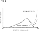
- FIG. 4 is a graph showing the relationship between the degree of vacuum and the amount of suction by the ejector.
- a solid line indicates the structure including a single orifice plate 44 with the aperture ratio of 60%
- a broken line indicates the structure including two orifice plates 44 with the aperture ratio of 75%.
- the structure including the single orifice plate 44 with the aperture ratio of 60% can sufficiently increase the threshold water temperature (refer to FIG. 3 ), the aperture ratio is small and the amount of suction decreases.
- the structure including the two orifice plates 44 with the aperture ratio of 75% can retain the intended amount of suction, in addition to sufficiently increasing the threshold water temperature. In other words, the use of more orifice plates 44 increases the threshold water temperature, while retaining the intended amount of suction with a greater aperture ratio.
- the ejector 40 includes the nozzle 41 that ejects the first fluid, the suction chamber 42 that sucks the second fluid using a pressure decrease caused by ejection of the first fluid through the nozzle 41, the diffuser 43 that discharges the first fluid ejected through the nozzle 41 and the second fluid sucked into the suction chamber 42 while raising the pressure of the first fluid and the second fluid, and at least one orifice plate 44 located downstream from the diffuser 43.
- the structure including the orifice plate 44 located downstream from the diffuser 43 can raise the pressure of the passage downstream from the diffuser 43. This structure thus sufficiently raises the pressure of the fluid passing through the diffuser 43, and enables the ejector 40 to function properly.
- the pipe 34 (in particular, the third pipe 34c) may be short to downsize the ejector 40 and thus the vacuum generation device 30.
- the pressure downstream from the diffuser 43 tends to be lower.
- the pressure of the fluid passing through the diffuser 43 may not be raised sufficiently.
- the orifice plate 44 used in this structure can sufficiently raise the pressure of the fluid passing through the diffuser 43.
- the structure including the orifice plate 44 is particularly effective for the ejector 40 and the vacuum generation device 30 that are compact.
- the at least one orifice plate 44 includes a plurality of orifice plates 44. This structure can raise the pressure in the passage downstream from the diffuser 43 without excessively reducing the flow rate of the fluid passing through the diffuser 43.
- the at least one orifice plate 44 has the opening 44a with a smaller cross-sectional area than passages upstream and downstream from the orifice plate 44 as the restrictor.
- the orifice plate 44 narrows the passage to increase the flow resistance.
- the vacuum generation device 30 includes the ejector 40, the drain tank 31 that stores the first fluid and the second fluid that have passed through the diffuser 43, and the pump 32 connected to the drain tank 31.
- the pump 32 pumps the fluid in the drain tank 31 to the ejector 40 as the first fluid.
- the pump 32 and the ejector 40 allow the fluid in the drain tank 31 to circulate through them and suck the second fluid through the ejector 40.
- the ejector 40 can function properly as described above, and the second fluid can be sucked through the ejector 40 properly.
- the ejector 40 and the vacuum generation device 30 are usable for systems other than the vacuum steam heating system 1.
- the ejector 40 and the vacuum generation device 30 may be used for a system that performs cooling in addition to heating with steam.
- the steam used in such systems may not be steam at an atmospheric pressure or less.
- the ejector 40 circulates water in the above embodiments, the ejector 40 may not be a liquid ejector.
- the ejector 40 may circulate a gas.
- the flow restrictor may have any structure that increases the flow resistance to higher than the resistance in parts upstream and downstream from the flow restrictor.
- the flow restrictor may be a choke that gradually narrows the cross-sectional area of a passage, a valve that reduces the cross-sectional area of a passage, or may be a bellow tube.
- the structure according to the above embodiments includes the two orifice plates 44 as flow restrictors, the structure may include a single flow restrictor or three or more flow restrictors.
- the technique according to the disclosure is applicable to the ejector and the vacuum generation device including the ejector.
Landscapes
- Engineering & Computer Science (AREA)
- Physics & Mathematics (AREA)
- Fluid Mechanics (AREA)
- Mechanical Engineering (AREA)
- General Engineering & Computer Science (AREA)
- Jet Pumps And Other Pumps (AREA)
Abstract
Description
- The disclosure relates to an ejector and a vacuum generation device including the ejector.
- An ejector and a vacuum generation device including the ejector are known. For example, a vacuum generation device described in Patent Literature 1 circulates a fluid stored in a tank through a pump and an ejector as a first fluid to allow the ejector to generate a suction force, which sucks a second fluid.
- Patent Literature 1: Japanese Unexamined Patent Application Publication No.
2014-156814 - The ejector includes a nozzle and a diffuser that are designed to suck the second fluid as intended.
- However, the ejector including the nozzle and the diffuser designed as above may fail to suck the second fluid as intended if the ejector malfunctions. The ejector may malfunction when, for example, the pressure of the fluid passing through the diffuser is not raised sufficiently.
- In response to the above issue, one or more aspects of the disclosure are directed to an ejector that functions properly.
- An ejector according to one aspect of the disclosure includes a nozzle that ejects a first fluid, a suction chamber that sucks a second fluid using a pressure decrease caused by ejection of the first fluid through the nozzle, a diffuser that discharges the first fluid ejected through the nozzle and the second fluid sucked into the suction chamber while raising a pressure of the first fluid and the second fluid, and at least one flow restrictor located downstream from the diffuser.
- A vacuum generation device according to another aspect of the disclosure includes the ejector, a tank that stores the first fluid and the second fluid that have passed through the diffuser, and a pump connected to the tank. The pump pumps a fluid in the tank to the ejector as the first fluid. The pump and the ejector allow the fluid in the tank to circulate through them and suck the second fluid through the ejector.
- The ejector according to the above aspect includes the flow restrictor located downstream from the diffuser to sufficiently raise the pressure of the fluid passing through the diffuser. The ejector can thus function properly.
- The vacuum generation device according to the above aspect includes the flow restrictor located downstream from the diffuser to sufficiently raise the pressure of the fluid passing through the diffuser. The ejector can thus function properly. The vacuum generation device can suck the second fluid properly.
-
- [
FIG. 1] FIG. 1 is a schematic diagram of piping for a vacuum steam heating system according to one embodiment. - [
FIG. 2] FIG. 2 is a schematic diagram of a vacuum generation device. - [
FIG. 3] FIG. 3 is a graph showing the relationship between the aperture ratio of an orifice plate and the circulating water temperature in association with a vacuum failure. - [
FIG. 4] FIG. 4 is a graph showing the relationship between the degree of vacuum and the amount of suction by an ejector. - Embodiments will be described by way of example with reference to the drawings. The embodiments described below are preferred examples, and do not limit the scope, applications, and uses of the present invention.
-
FIG. 1 is a schematic diagram of piping for a vacuum steam heating system 1 according to one embodiment. - The vacuum steam heating system (hereafter, the heating system) 1 includes a
reaction tank 20, which heats an object with steam, asteam supply pipe 11, which supplies steam to thereaction tank 20 from a steam generator (not shown), adischarge pipe 13, which discharges a drain generated in thereaction tank 20, and avacuum generation device 30, which sucks the drain through thedischarge pipe 13. The heating system 1 includes afluid circuit 10, which includes thesteam supply pipe 11, thereaction tank 20, thedischarge pipe 13, and thevacuum generation device 30. The heating system 1 heats an object placed in thereaction tank 20 with saturated steam at an atmospheric pressure or less. - The
reaction tank 20 includes atank body 21, in which an object is placed, and ajacket 22, which extends along substantially the entire periphery of thetank body 21. Thesteam supply pipe 11 is connected to thejacket 22. Thesteam supply pipe 11 includes asupply valve 14, which is an on-off valve. Steam generated in the steam generator is supplied to thejacket 22 through thesteam supply pipe 11. The steam supplied to thejacket 22 indirectly exchanges heat with the object placed in thetank body 21 in thereaction tank 20 to condense (or liquefy) and heat the object in thetank body 21. More specifically, the object is heated with the condensed latent heat from the steam. - The
discharge pipe 13 has one end (inlet end) connected to a lower end part of thejacket 22, and the other end (outlet end) connected to thevacuum generation device 30. Thedischarge pipe 13 discharges the drain (condensate) generated from the steam condensed in thejacket 22. Thedischarge pipe 13 includes asteam trap 15, which automatically discharges only the drain flowing into thesteam trap 15. - The
vacuum generation device 30 includes adrain tank 31, which stores the drain, apump 32, which pumps the drain in thedrain tank 31, and anejector 40, which sucks the drain from thereaction tank 20 through thedischarge pipe 13. Thedrain tank 31, thepump 32, and theejector 40 are connected to one another with apipe 34. This forms a circulation passage including thedrain tank 31, thepump 32, and theejector 40. Thevacuum generation device 30 circulates the drain stored in thedrain tank 31 through thepump 32 and theejector 40 to cause theejector 40 to generate a suction force, which then sucks the drain from thereaction tank 20. -
FIG. 2 is a schematic diagram of thevacuum generation device 30. Thepipe 34 includes afirst pipe 34a connecting thedrain tank 31 and thepump 32, asecond pipe 34b connecting thepump 32 and theejector 40, and athird pipe 34c connecting theejector 40 and thedrain tank 31. Thedrain tank 31 is an example of the tank. Thepump 32 is driven by amotor 35. - The
ejector 40 includes anozzle 41 for ejecting a first fluid, asuction chamber 42, which uses a negative pressure generated by the first fluid ejected through thenozzle 41 to suck a second fluid, adiffuser 43, which discharges the first fluid ejected through thenozzle 41 and the second fluid sucked into thesuction chamber 42 while raising their pressure, and twoorifice plates 44 located downstream from thediffuser 43. - The
nozzle 41 is connected to a downstream end of thesecond pipe 34b. Thenozzle 41 has aninjection hole 41a located at least inside thesuction chamber 42. - The
suction chamber 42 also contains at least an upstream end part of thediffuser 43. Thedischarge pipe 13 has the outlet end connected into thesuction chamber 42. In thesuction chamber 42, the second fluid is sucked from thedischarge pipe 13 under a negative pressure (pressure decrease) caused by ejection of the first fluid through thenozzle 41. In thesuction chamber 42, the negative pressure resulting from the jet pumping of the first fluid generates a suction force for sucking the second fluid. - The
diffuser 43 defines a linear passage. The cross-sectional area of the passage defined in thediffuser 43 increases from upstream to downstream. A fluid passing through thediffuser 43 thus decelerates, and the pressure of the fluid increases the fluid flows from upstream to downstream. Thethird pipe 34c is connected to the downstream end of thediffuser 43. - The
orifice plates 44 are disc-shaped, and each have a circularcentral opening 44a. Theorifice plates 44 are an example of a flow restrictor. Theorifice plates 44 are located inside thethird pipe 34c. More specifically, theupstream orifice plate 44 is located on an upstream end of thethird pipe 34c, or is located at a joint between thediffuser 43 and thethird pipe 34c. Thedownstream orifice plate 44 is located on a downstream end of thethird pipe 34c, or is located at a joint between thethird pipe 34c and thedrain tank 31. Thediffuser 43 and thethird pipe 34c are connected to each other at their flanges. Theupstream orifice plate 44 is located between the flange of thediffuser 43 and the flange of thethird pipe 34c. Thethird pipe 34c and thedrain tank 31 are connected to each other at their flanges. Thedownstream orifice plate 44 is located between the flange of thethird pipe 34c and the flange of thedrain tank 31. - The
opening 44a in theupstream orifice plate 44 has an area smaller than the cross-sectional area of a passage in the part of thethird pipe 34c downstream from theorifice plate 44. In the same manner, theopening 44a in thedownstream orifice plate 44 has an area smaller than the cross-sectional area of a passage in the part of thethird pipe 34c upstream from theorifice plate 44. More specifically, the upstream anddownstream orifice plates 44 function as chokes to narrow the cross-sectional area of the passage downstream from thediffuser 43. - The
opening 44a in theupstream orifice plate 44 has the same area as theopening 44a in thedownstream orifice plate 44. The cross-sectional area of the passage in thethird pipe 34c is uniform from upstream to downstream. For theupstream orifice plate 44, the ratio of the area of theopening 44a to the cross-sectional area of the passage in thethird pipe 34c (the area of theopening 44a/the cross-sectional area of the passage in thethird pipe 34c, or hereafter the aperture ratio) is equal to the aperture ratio of thedownstream orifice plate 44. - The
vacuum generation device 30 with the structure described above supplies the drain inside thedrain tank 31 with the pressure being raised by thepump 32 to thenozzle 41 in theejector 40 as the first fluid. The drain is ejected through thenozzle 41 into thesuction chamber 42 to generate a negative pressure around thenozzle 41, which then sucks the drain in thereaction tank 20 into thesuction chamber 42 through thedischarge pipe 13 as the second fluid. The drain ejected through thenozzle 41 and the drain sucked from thedischarge pipe 13 mix in thesuction chamber 42. The resultant drain is then discharged through thediffuser 43. In this state, the drain decelerates and the pressure of the drain increases when flowing downstream through thediffuser 43. The drain finally flows into thedrain tank 41. The drain in thereaction tank 20 is collected into thedrain tank 31. - The
orifice plates 44 located downstream from thediffuser 43 allow theejector 40 to function properly, and the drain to be properly sucked from thereaction tank 20. - More specifically, the
orifice plates 44 located downstream from thediffuser 43 increase the flow resistance in the passage downstream from thediffuser 43 and increase the fluid pressure in the passage downstream from thediffuser 43. This sufficiently raises the pressure of the fluid passing through thediffuser 43. At a low fluid pressure downstream from thediffuser 43, the pressure of the fluid passing through thediffuser 43 may not be raised sufficiently. In theejector 40, thenozzle 41 and thediffuser 43 are designed based on the pressure difference between the inlet of thenozzle 41 and the outlet of thediffuser 43. If this pressure difference is too small, theejector 40 cannot have an intended negative pressure generated in thesuction chamber 42. Theorifice plates 44 located downstream from thediffuser 43 allow a sufficiently large increase in the pressure of the fluid passing through thediffuser 43. This generates an intended negative pressure in thesuction chamber 42. Theejector 40 can thus function properly. - The
diffuser 43 may or may not sufficiently raise the pressure of the fluid depending on the temperature of the drain circulating through the vacuum generation device 30 (hereafter, the circulating water temperature) in addition to the pressure downstream from thediffuser 43. As the circulating water temperature is higher, the drain has lower viscosity, and thus causes a smaller pressure increase (pressure recovery) in the drain passing through thediffuser 43. In other words, as the circulating water temperature is higher, an intended negative pressure is less likely to be generated in thesuction chamber 42. -
FIG. 3 is a graph showing the relationship between the aperture ratio of theorifice plate 44 and the circulating water temperature in association with a failure to generate an intended negative pressure in the suction chamber 42 (hereafter, a vacuum failure). A solid line inFIG. 3 indicates a threshold at which a vacuum failure occurs when asingle orifice plate 44 is used. A vacuum failure can occur in an area defined above the threshold, or an area in which the circulating water temperature is higher than the threshold (a hatched area for the threshold indicated by the solid line in the figure). A broken line inFIG. 3 indicates a threshold at which a vacuum failure occurs when twoorifice plates 44 are used. - With no
orifice plate 44 being used (corresponding to the aperture ratio of 100%), the circulating water temperature at the threshold at which no vacuum failure occurs (hereafter, the threshold water temperature) is T1. As shown inFIG. 3 , the threshold water temperature can be higher as theopening 44a in theorifice plate 44 is smaller. In other words, the circulating water temperature at which no vacuum failure occurs can be higher. With the twoorifice plates 44 being used, instead of thesingle orifice plate 44, the threshold water temperature can be still higher (as indicated by the broken line), because the use ofmore orifice plates 44 raises the pressure more in the passage downstream from thediffuser 43. - However, the
orifice plate 44 having a smaller aperture ratio may have a flow resistance that is too high. This may decrease the flow rate of the drain passing through thethird pipe 34c, or the flow rate of the drain passing through thediffuser 43. This lowers the flow rate of the drain to be sucked from thereaction tank 20 through thedischarge pipe 13. - In contrast,
multiple orifice plates 44 may be used to increase the flow resistance while retaining the intended flow rate.FIG. 4 is a graph showing the relationship between the degree of vacuum and the amount of suction by the ejector. InFIG. 4 , a solid line indicates the structure including asingle orifice plate 44 with the aperture ratio of 60%, whereas a broken line indicates the structure including twoorifice plates 44 with the aperture ratio of 75%. When the degree of vacuum is high (e.g., 100 kPaG), or specifically when theejector 40 functions properly, the structure including the twoorifice plates 44 with the aperture ratio of 75% has a larger amount of suction than the structure including thesingle orifice plate 44 with the aperture ratio of 60%. Although the structure including thesingle orifice plate 44 with the aperture ratio of 60% can sufficiently increase the threshold water temperature (refer toFIG. 3 ), the aperture ratio is small and the amount of suction decreases. In contrast, the structure including the twoorifice plates 44 with the aperture ratio of 75% can retain the intended amount of suction, in addition to sufficiently increasing the threshold water temperature. In other words, the use ofmore orifice plates 44 increases the threshold water temperature, while retaining the intended amount of suction with a greater aperture ratio. - As described above, the
ejector 40 includes thenozzle 41 that ejects the first fluid, thesuction chamber 42 that sucks the second fluid using a pressure decrease caused by ejection of the first fluid through thenozzle 41, thediffuser 43 that discharges the first fluid ejected through thenozzle 41 and the second fluid sucked into thesuction chamber 42 while raising the pressure of the first fluid and the second fluid, and at least oneorifice plate 44 located downstream from thediffuser 43. - The structure including the
orifice plate 44 located downstream from thediffuser 43 can raise the pressure of the passage downstream from thediffuser 43. This structure thus sufficiently raises the pressure of the fluid passing through thediffuser 43, and enables theejector 40 to function properly. - For example, the pipe 34 (in particular, the
third pipe 34c) may be short to downsize theejector 40 and thus thevacuum generation device 30. In this case, the pressure downstream from thediffuser 43 tends to be lower. The pressure of the fluid passing through thediffuser 43 may not be raised sufficiently. Theorifice plate 44 used in this structure can sufficiently raise the pressure of the fluid passing through thediffuser 43. In other words, the structure including theorifice plate 44 is particularly effective for theejector 40 and thevacuum generation device 30 that are compact. - The
orifice plate 44 narrows the cross-sectional area of the passage from its peripheral portion, and thus allows the fluid to have an appropriate pressure decrease without excessively disturbing the outwardly diverging flow of the fluid. - The at least one
orifice plate 44 includes a plurality oforifice plates 44. This structure can raise the pressure in the passage downstream from thediffuser 43 without excessively reducing the flow rate of the fluid passing through thediffuser 43. - Further, the at least one
orifice plate 44 has theopening 44a with a smaller cross-sectional area than passages upstream and downstream from theorifice plate 44 as the restrictor. - The
orifice plate 44 narrows the passage to increase the flow resistance. - The
vacuum generation device 30 includes theejector 40, thedrain tank 31 that stores the first fluid and the second fluid that have passed through thediffuser 43, and thepump 32 connected to thedrain tank 31. Thepump 32 pumps the fluid in thedrain tank 31 to theejector 40 as the first fluid. Thepump 32 and theejector 40 allow the fluid in thedrain tank 31 to circulate through them and suck the second fluid through theejector 40. - In this structure, the
ejector 40 can function properly as described above, and the second fluid can be sucked through theejector 40 properly. - The
ejector 40 and thevacuum generation device 30 are usable for systems other than the vacuum steam heating system 1. For example, theejector 40 and thevacuum generation device 30 may be used for a system that performs cooling in addition to heating with steam. The steam used in such systems may not be steam at an atmospheric pressure or less. - Although the
ejector 40 circulates water in the above embodiments, theejector 40 may not be a liquid ejector. Theejector 40 may circulate a gas. - Although the orifice plate is used as the flow restrictor in the above embodiments, the flow restrictor may have any structure that increases the flow resistance to higher than the resistance in parts upstream and downstream from the flow restrictor. For example, the flow restrictor may be a choke that gradually narrows the cross-sectional area of a passage, a valve that reduces the cross-sectional area of a passage, or may be a bellow tube.
- Although the structure according to the above embodiments includes the two
orifice plates 44 as flow restrictors, the structure may include a single flow restrictor or three or more flow restrictors. - The technique according to the disclosure is applicable to the ejector and the vacuum generation device including the ejector.
-
- 1
- vacuum steam heating system
- 30
- vacuum generation device
- 31
- drain tank (tank)
- 32
- pump
- 40
- ejector
- 41
- nozzle
- 42
- suction chamber
- 43
- diffuser
- 44
- orifice (flow restrictor)
Claims (5)
- An ejector, comprising:a nozzle configured to eject a first fluid;a suction chamber configured to suck a second fluid using a pressure decrease caused by ejection of the first fluid through the nozzle;a diffuser configured to discharge the first fluid ejected through the nozzle and the second fluid sucked into the suction chamber while raising a pressure of the first fluid and the second fluid; andat least one flow restrictor located downstream from the diffuser.
- The ejector according to claim 1, wherein
the flow restrictor comprises a plurality of flow restrictors. - The ejector according to claim 1 or claim 2, wherein
the flow restrictor has a passage with a smaller cross-sectional area than passages upstream and downstream from the flow restrictor. - The ejector according to any one of claims 1 to 3, wherein
the flow restrictor includes an orifice plate. - A vacuum generation device, comprising:the ejector according to any one of claims 1 to 4;a tank configured to store the first fluid and the second fluid that have passed through the diffuser; anda pump connected to the tank, the pump being configured to pump a fluid in the tank to the ejector as the first fluid,wherein the pump and the ejector allow the fluid in the tank to circulate therethrough and suck the second fluid through the ejector.
Applications Claiming Priority (2)
| Application Number | Priority Date | Filing Date | Title |
|---|---|---|---|
| JP2015184383 | 2015-09-17 | ||
| PCT/JP2016/075519 WO2017047387A1 (en) | 2015-09-17 | 2016-08-31 | Ejector and vacuum generation device with same |
Publications (3)
| Publication Number | Publication Date |
|---|---|
| EP3351805A1 true EP3351805A1 (en) | 2018-07-25 |
| EP3351805A4 EP3351805A4 (en) | 2018-08-22 |
| EP3351805B1 EP3351805B1 (en) | 2025-05-21 |
Family
ID=58288904
Family Applications (1)
| Application Number | Title | Priority Date | Filing Date |
|---|---|---|---|
| EP16846258.8A Active EP3351805B1 (en) | 2015-09-17 | 2016-08-31 | Ejector and vacuum generation device with same |
Country Status (3)
| Country | Link |
|---|---|
| EP (1) | EP3351805B1 (en) |
| JP (1) | JP6088719B1 (en) |
| WO (1) | WO2017047387A1 (en) |
Families Citing this family (1)
| Publication number | Priority date | Publication date | Assignee | Title |
|---|---|---|---|---|
| CN108980120B (en) * | 2017-06-05 | 2021-08-31 | 深圳市和科达超声设备有限公司 | Vacuum generator and method for manufacturing the same |
Family Cites Families (10)
| Publication number | Priority date | Publication date | Assignee | Title |
|---|---|---|---|---|
| US1345639A (en) * | 1914-09-14 | 1920-07-06 | Westinghouse Electric & Mfg Co | Fluid-translating device |
| JPS5033310U (en) * | 1973-07-19 | 1975-04-10 | ||
| JPS63168300U (en) * | 1987-04-24 | 1988-11-01 | ||
| US5628623A (en) * | 1993-02-12 | 1997-05-13 | Skaggs; Bill D. | Fluid jet ejector and ejection method |
| FR2746484B1 (en) * | 1996-03-25 | 1998-04-24 | Commissariat Energie Atomique | PRESSURE WATER SUPPLY DEVICE FOR THE WATER SOURCE OF A STEAM INJECTOR |
| JP3966157B2 (en) * | 2002-10-25 | 2007-08-29 | 株式会社デンソー | Ejector |
| DE10255472B3 (en) * | 2002-11-28 | 2004-07-01 | Festo Ag & Co. | Ejector pump for producing vacuum for suction cup has compressed-air connection to Laval nozzle with air jet passing through suction chamber into mixing tube leading to eddy chamber |
| US7487795B2 (en) * | 2005-05-19 | 2009-02-10 | Delaware Capital Formation | Chemical dispenser |
| CN103459855B (en) * | 2011-03-28 | 2016-03-16 | 株式会社小金井 | ejector |
| JP6130160B2 (en) * | 2013-02-15 | 2017-05-17 | 株式会社テイエルブイ | Ejector type vacuum pump |
-
2016
- 2016-08-31 JP JP2016570360A patent/JP6088719B1/en active Active
- 2016-08-31 WO PCT/JP2016/075519 patent/WO2017047387A1/en not_active Ceased
- 2016-08-31 EP EP16846258.8A patent/EP3351805B1/en active Active
Also Published As
| Publication number | Publication date |
|---|---|
| JPWO2017047387A1 (en) | 2017-09-14 |
| JP6088719B1 (en) | 2017-03-01 |
| WO2017047387A1 (en) | 2017-03-23 |
| EP3351805B1 (en) | 2025-05-21 |
| EP3351805A4 (en) | 2018-08-22 |
Similar Documents
| Publication | Publication Date | Title |
|---|---|---|
| EP2223594B1 (en) | Agricultural sprayer | |
| JP6351131B2 (en) | Fluid line | |
| JP6452275B2 (en) | Thermo compressor | |
| SE0801668L (en) | Cooling device for welding device | |
| SA519402315B1 (en) | Ejector Device | |
| RU2463487C1 (en) | Injector-type pump and method of its operation | |
| CN104736933B (en) | Utilize the firing equipment of liquid fuel operation | |
| EP3351805B1 (en) | Ejector and vacuum generation device with same | |
| US11278470B2 (en) | Steam physiotherapeutic device | |
| CN107405532B (en) | Multistage distillation apparatus and method for operating the same | |
| JP2013108637A (en) | Heat exchanger | |
| JP5384152B2 (en) | Air heater | |
| US20200066244A1 (en) | Silencer | |
| JP4628934B2 (en) | Waste steam recovery device | |
| JP2009257653A (en) | Condensate recovering device | |
| JP4594270B2 (en) | Heat exchanger | |
| CN109642588B (en) | Oil tank | |
| KR101560593B1 (en) | Airpump boiler | |
| JP4628933B2 (en) | Waste steam recovery device | |
| JP2014074530A (en) | Condensate recovery device | |
| JP6830818B2 (en) | Branch pipe | |
| JP5301199B2 (en) | Condensate recovery device | |
| JP5546962B2 (en) | Vacuum steam heater | |
| KR101874736B1 (en) | Dual turbo pumps operating equipment | |
| JP5937905B2 (en) | Condensate recovery device |
Legal Events
| Date | Code | Title | Description |
|---|---|---|---|
| STAA | Information on the status of an ep patent application or granted ep patent |
Free format text: STATUS: THE INTERNATIONAL PUBLICATION HAS BEEN MADE |
|
| PUAI | Public reference made under article 153(3) epc to a published international application that has entered the european phase |
Free format text: ORIGINAL CODE: 0009012 |
|
| STAA | Information on the status of an ep patent application or granted ep patent |
Free format text: STATUS: REQUEST FOR EXAMINATION WAS MADE |
|
| 17P | Request for examination filed |
Effective date: 20180417 |
|
| AK | Designated contracting states |
Kind code of ref document: A1 Designated state(s): AL AT BE BG CH CY CZ DE DK EE ES FI FR GB GR HR HU IE IS IT LI LT LU LV MC MK MT NL NO PL PT RO RS SE SI SK SM TR |
|
| AX | Request for extension of the european patent |
Extension state: BA ME |
|
| A4 | Supplementary search report drawn up and despatched |
Effective date: 20180725 |
|
| RIC1 | Information provided on ipc code assigned before grant |
Ipc: F04F 5/44 20060101AFI20180719BHEP Ipc: F04F 5/10 20060101ALI20180719BHEP Ipc: F04F 5/04 20060101ALI20180719BHEP |
|
| DAV | Request for validation of the european patent (deleted) | ||
| DAX | Request for extension of the european patent (deleted) | ||
| STAA | Information on the status of an ep patent application or granted ep patent |
Free format text: STATUS: EXAMINATION IS IN PROGRESS |
|
| 17Q | First examination report despatched |
Effective date: 20210924 |
|
| GRAP | Despatch of communication of intention to grant a patent |
Free format text: ORIGINAL CODE: EPIDOSNIGR1 |
|
| STAA | Information on the status of an ep patent application or granted ep patent |
Free format text: STATUS: GRANT OF PATENT IS INTENDED |
|
| INTG | Intention to grant announced |
Effective date: 20241218 |
|
| GRAS | Grant fee paid |
Free format text: ORIGINAL CODE: EPIDOSNIGR3 |
|
| GRAA | (expected) grant |
Free format text: ORIGINAL CODE: 0009210 |
|
| STAA | Information on the status of an ep patent application or granted ep patent |
Free format text: STATUS: THE PATENT HAS BEEN GRANTED |
|
| AK | Designated contracting states |
Kind code of ref document: B1 Designated state(s): AL AT BE BG CH CY CZ DE DK EE ES FI FR GB GR HR HU IE IS IT LI LT LU LV MC MK MT NL NO PL PT RO RS SE SI SK SM TR |
|
| REG | Reference to a national code |
Ref country code: GB Ref legal event code: FG4D |
|
| REG | Reference to a national code |
Ref country code: CH Ref legal event code: EP |
|
| REG | Reference to a national code |
Ref country code: DE Ref legal event code: R096 Ref document number: 602016092338 Country of ref document: DE |
|
| REG | Reference to a national code |
Ref country code: IE Ref legal event code: FG4D |
|
| P01 | Opt-out of the competence of the unified patent court (upc) registered |
Free format text: CASE NUMBER: APP_26410/2025 Effective date: 20250604 |
|
| REG | Reference to a national code |
Ref country code: NL Ref legal event code: MP Effective date: 20250521 |
|
| PG25 | Lapsed in a contracting state [announced via postgrant information from national office to epo] |
Ref country code: ES Free format text: LAPSE BECAUSE OF FAILURE TO SUBMIT A TRANSLATION OF THE DESCRIPTION OR TO PAY THE FEE WITHIN THE PRESCRIBED TIME-LIMIT Effective date: 20250521 Ref country code: FI Free format text: LAPSE BECAUSE OF FAILURE TO SUBMIT A TRANSLATION OF THE DESCRIPTION OR TO PAY THE FEE WITHIN THE PRESCRIBED TIME-LIMIT Effective date: 20250521 Ref country code: PT Free format text: LAPSE BECAUSE OF FAILURE TO SUBMIT A TRANSLATION OF THE DESCRIPTION OR TO PAY THE FEE WITHIN THE PRESCRIBED TIME-LIMIT Effective date: 20250922 |
|
| PGFP | Annual fee paid to national office [announced via postgrant information from national office to epo] |
Ref country code: DE Payment date: 20250820 Year of fee payment: 10 |
|
| REG | Reference to a national code |
Ref country code: LT Ref legal event code: MG9D |
|
| PG25 | Lapsed in a contracting state [announced via postgrant information from national office to epo] |
Ref country code: NO Free format text: LAPSE BECAUSE OF FAILURE TO SUBMIT A TRANSLATION OF THE DESCRIPTION OR TO PAY THE FEE WITHIN THE PRESCRIBED TIME-LIMIT Effective date: 20250821 Ref country code: GR Free format text: LAPSE BECAUSE OF FAILURE TO SUBMIT A TRANSLATION OF THE DESCRIPTION OR TO PAY THE FEE WITHIN THE PRESCRIBED TIME-LIMIT Effective date: 20250822 |
|
| PG25 | Lapsed in a contracting state [announced via postgrant information from national office to epo] |
Ref country code: PL Free format text: LAPSE BECAUSE OF FAILURE TO SUBMIT A TRANSLATION OF THE DESCRIPTION OR TO PAY THE FEE WITHIN THE PRESCRIBED TIME-LIMIT Effective date: 20250521 Ref country code: NL Free format text: LAPSE BECAUSE OF FAILURE TO SUBMIT A TRANSLATION OF THE DESCRIPTION OR TO PAY THE FEE WITHIN THE PRESCRIBED TIME-LIMIT Effective date: 20250521 |
|
| PG25 | Lapsed in a contracting state [announced via postgrant information from national office to epo] |
Ref country code: BG Free format text: LAPSE BECAUSE OF FAILURE TO SUBMIT A TRANSLATION OF THE DESCRIPTION OR TO PAY THE FEE WITHIN THE PRESCRIBED TIME-LIMIT Effective date: 20250521 |
|
| PGFP | Annual fee paid to national office [announced via postgrant information from national office to epo] |
Ref country code: GB Payment date: 20250821 Year of fee payment: 10 |
|
| PG25 | Lapsed in a contracting state [announced via postgrant information from national office to epo] |
Ref country code: HR Free format text: LAPSE BECAUSE OF FAILURE TO SUBMIT A TRANSLATION OF THE DESCRIPTION OR TO PAY THE FEE WITHIN THE PRESCRIBED TIME-LIMIT Effective date: 20250521 |
|
| PGFP | Annual fee paid to national office [announced via postgrant information from national office to epo] |
Ref country code: FR Payment date: 20250828 Year of fee payment: 10 |
|
| PG25 | Lapsed in a contracting state [announced via postgrant information from national office to epo] |
Ref country code: RS Free format text: LAPSE BECAUSE OF FAILURE TO SUBMIT A TRANSLATION OF THE DESCRIPTION OR TO PAY THE FEE WITHIN THE PRESCRIBED TIME-LIMIT Effective date: 20250821 |
|
| PG25 | Lapsed in a contracting state [announced via postgrant information from national office to epo] |
Ref country code: IS Free format text: LAPSE BECAUSE OF FAILURE TO SUBMIT A TRANSLATION OF THE DESCRIPTION OR TO PAY THE FEE WITHIN THE PRESCRIBED TIME-LIMIT Effective date: 20250921 |
|
| PG25 | Lapsed in a contracting state [announced via postgrant information from national office to epo] |
Ref country code: LV Free format text: LAPSE BECAUSE OF FAILURE TO SUBMIT A TRANSLATION OF THE DESCRIPTION OR TO PAY THE FEE WITHIN THE PRESCRIBED TIME-LIMIT Effective date: 20250521 |
|
| REG | Reference to a national code |
Ref country code: AT Ref legal event code: MK05 Ref document number: 1796959 Country of ref document: AT Kind code of ref document: T Effective date: 20250521 |
|
| PG25 | Lapsed in a contracting state [announced via postgrant information from national office to epo] |
Ref country code: SM Free format text: LAPSE BECAUSE OF FAILURE TO SUBMIT A TRANSLATION OF THE DESCRIPTION OR TO PAY THE FEE WITHIN THE PRESCRIBED TIME-LIMIT Effective date: 20250521 Ref country code: AT Free format text: LAPSE BECAUSE OF FAILURE TO SUBMIT A TRANSLATION OF THE DESCRIPTION OR TO PAY THE FEE WITHIN THE PRESCRIBED TIME-LIMIT Effective date: 20250521 Ref country code: DK Free format text: LAPSE BECAUSE OF FAILURE TO SUBMIT A TRANSLATION OF THE DESCRIPTION OR TO PAY THE FEE WITHIN THE PRESCRIBED TIME-LIMIT Effective date: 20250521 |
|
| PG25 | Lapsed in a contracting state [announced via postgrant information from national office to epo] |
Ref country code: CZ Free format text: LAPSE BECAUSE OF FAILURE TO SUBMIT A TRANSLATION OF THE DESCRIPTION OR TO PAY THE FEE WITHIN THE PRESCRIBED TIME-LIMIT Effective date: 20250521 |
|
| PG25 | Lapsed in a contracting state [announced via postgrant information from national office to epo] |
Ref country code: EE Free format text: LAPSE BECAUSE OF FAILURE TO SUBMIT A TRANSLATION OF THE DESCRIPTION OR TO PAY THE FEE WITHIN THE PRESCRIBED TIME-LIMIT Effective date: 20250521 |
|
| PG25 | Lapsed in a contracting state [announced via postgrant information from national office to epo] |
Ref country code: RO Free format text: LAPSE BECAUSE OF FAILURE TO SUBMIT A TRANSLATION OF THE DESCRIPTION OR TO PAY THE FEE WITHIN THE PRESCRIBED TIME-LIMIT Effective date: 20250521 Ref country code: SK Free format text: LAPSE BECAUSE OF FAILURE TO SUBMIT A TRANSLATION OF THE DESCRIPTION OR TO PAY THE FEE WITHIN THE PRESCRIBED TIME-LIMIT Effective date: 20250521 |
|
| PG25 | Lapsed in a contracting state [announced via postgrant information from national office to epo] |
Ref country code: IT Free format text: LAPSE BECAUSE OF FAILURE TO SUBMIT A TRANSLATION OF THE DESCRIPTION OR TO PAY THE FEE WITHIN THE PRESCRIBED TIME-LIMIT Effective date: 20250521 |
|
| REG | Reference to a national code |
Ref country code: DE Ref legal event code: R097 Ref document number: 602016092338 Country of ref document: DE |
|
| REG | Reference to a national code |
Ref country code: CH Ref legal event code: H13 Free format text: ST27 STATUS EVENT CODE: U-0-0-H10-H13 (AS PROVIDED BY THE NATIONAL OFFICE) Effective date: 20260324 |
|
| PLBE | No opposition filed within time limit |
Free format text: ORIGINAL CODE: 0009261 |
|
| STAA | Information on the status of an ep patent application or granted ep patent |
Free format text: STATUS: NO OPPOSITION FILED WITHIN TIME LIMIT |
|
| PG25 | Lapsed in a contracting state [announced via postgrant information from national office to epo] |
Ref country code: MC Free format text: LAPSE BECAUSE OF FAILURE TO SUBMIT A TRANSLATION OF THE DESCRIPTION OR TO PAY THE FEE WITHIN THE PRESCRIBED TIME-LIMIT Effective date: 20250521 |
|
| REG | Reference to a national code |
Ref country code: CH Ref legal event code: L10 Free format text: ST27 STATUS EVENT CODE: U-0-0-L10-L00 (AS PROVIDED BY THE NATIONAL OFFICE) Effective date: 20260402 |
|
| PG25 | Lapsed in a contracting state [announced via postgrant information from national office to epo] |
Ref country code: LU Free format text: LAPSE BECAUSE OF NON-PAYMENT OF DUE FEES Effective date: 20250831 |
|
| PG25 | Lapsed in a contracting state [announced via postgrant information from national office to epo] |
Ref country code: CH Free format text: LAPSE BECAUSE OF NON-PAYMENT OF DUE FEES Effective date: 20250831 |
|
| 26N | No opposition filed |
Effective date: 20260224 |