EP3351757A1 - System and method for attenuating sound produced by a vehicle - Google Patents
System and method for attenuating sound produced by a vehicle Download PDFInfo
- Publication number
- EP3351757A1 EP3351757A1 EP17163931.3A EP17163931A EP3351757A1 EP 3351757 A1 EP3351757 A1 EP 3351757A1 EP 17163931 A EP17163931 A EP 17163931A EP 3351757 A1 EP3351757 A1 EP 3351757A1
- Authority
- EP
- European Patent Office
- Prior art keywords
- sound
- vehicle
- location
- ecu
- sound reduction
- Prior art date
- Legal status (The legal status is an assumption and is not a legal conclusion. Google has not performed a legal analysis and makes no representation as to the accuracy of the status listed.)
- Granted
Links
Images


Classifications
-
- G—PHYSICS
- G10—MUSICAL INSTRUMENTS; ACOUSTICS
- G10K—SOUND-PRODUCING DEVICES; METHODS OR DEVICES FOR PROTECTING AGAINST, OR FOR DAMPING, NOISE OR OTHER ACOUSTIC WAVES IN GENERAL; ACOUSTICS NOT OTHERWISE PROVIDED FOR
- G10K11/00—Methods or devices for transmitting, conducting or directing sound in general; Methods or devices for protecting against, or for damping, noise or other acoustic waves in general
- G10K11/02—Mechanical acoustic impedances; Impedance matching, e.g. by horns; Acoustic resonators
- G10K11/04—Acoustic filters ; Acoustic resonators
-
- F—MECHANICAL ENGINEERING; LIGHTING; HEATING; WEAPONS; BLASTING
- F01—MACHINES OR ENGINES IN GENERAL; ENGINE PLANTS IN GENERAL; STEAM ENGINES
- F01N—GAS-FLOW SILENCERS OR EXHAUST APPARATUS FOR MACHINES OR ENGINES IN GENERAL; GAS-FLOW SILENCERS OR EXHAUST APPARATUS FOR INTERNAL-COMBUSTION ENGINES
- F01N1/00—Silencing apparatus characterised by method of silencing
- F01N1/16—Silencing apparatus characterised by method of silencing by using movable parts
- F01N1/168—Silencing apparatus characterised by method of silencing by using movable parts for controlling or modifying silencing characteristics only
-
- F—MECHANICAL ENGINEERING; LIGHTING; HEATING; WEAPONS; BLASTING
- F01—MACHINES OR ENGINES IN GENERAL; ENGINE PLANTS IN GENERAL; STEAM ENGINES
- F01N—GAS-FLOW SILENCERS OR EXHAUST APPARATUS FOR MACHINES OR ENGINES IN GENERAL; GAS-FLOW SILENCERS OR EXHAUST APPARATUS FOR INTERNAL-COMBUSTION ENGINES
- F01N1/00—Silencing apparatus characterised by method of silencing
-
- F—MECHANICAL ENGINEERING; LIGHTING; HEATING; WEAPONS; BLASTING
- F01—MACHINES OR ENGINES IN GENERAL; ENGINE PLANTS IN GENERAL; STEAM ENGINES
- F01N—GAS-FLOW SILENCERS OR EXHAUST APPARATUS FOR MACHINES OR ENGINES IN GENERAL; GAS-FLOW SILENCERS OR EXHAUST APPARATUS FOR INTERNAL-COMBUSTION ENGINES
- F01N1/00—Silencing apparatus characterised by method of silencing
- F01N1/16—Silencing apparatus characterised by method of silencing by using movable parts
- F01N1/18—Silencing apparatus characterised by method of silencing by using movable parts having rotary movement
-
- F—MECHANICAL ENGINEERING; LIGHTING; HEATING; WEAPONS; BLASTING
- F01—MACHINES OR ENGINES IN GENERAL; ENGINE PLANTS IN GENERAL; STEAM ENGINES
- F01N—GAS-FLOW SILENCERS OR EXHAUST APPARATUS FOR MACHINES OR ENGINES IN GENERAL; GAS-FLOW SILENCERS OR EXHAUST APPARATUS FOR INTERNAL-COMBUSTION ENGINES
- F01N13/00—Exhaust or silencing apparatus characterised by constructional features
- F01N13/02—Exhaust or silencing apparatus characterised by constructional features having two or more separate silencers in series
-
- F—MECHANICAL ENGINEERING; LIGHTING; HEATING; WEAPONS; BLASTING
- F02—COMBUSTION ENGINES; HOT-GAS OR COMBUSTION-PRODUCT ENGINE PLANTS
- F02D—CONTROLLING COMBUSTION ENGINES
- F02D41/00—Electrical control of supply of combustible mixture or its constituents
- F02D41/02—Circuit arrangements for generating control signals
- F02D41/021—Introducing corrections for particular conditions exterior to the engine
-
- G—PHYSICS
- G01—MEASURING; TESTING
- G01H—MEASUREMENT OF MECHANICAL VIBRATIONS OR ULTRASONIC, SONIC OR INFRASONIC WAVES
- G01H17/00—Measuring mechanical vibrations or ultrasonic, sonic or infrasonic waves, not provided for in the other groups of this subclass
-
- G—PHYSICS
- G01—MEASURING; TESTING
- G01J—MEASUREMENT OF INTENSITY, VELOCITY, SPECTRAL CONTENT, POLARISATION, PHASE OR PULSE CHARACTERISTICS OF INFRARED, VISIBLE OR ULTRAVIOLET LIGHT; COLORIMETRY; RADIATION PYROMETRY
- G01J1/00—Photometry, e.g. photographic exposure meter
- G01J1/10—Photometry, e.g. photographic exposure meter by comparison with reference light or electric value provisionally void
- G01J1/16—Photometry, e.g. photographic exposure meter by comparison with reference light or electric value provisionally void using electric radiation detectors
-
- F—MECHANICAL ENGINEERING; LIGHTING; HEATING; WEAPONS; BLASTING
- F01—MACHINES OR ENGINES IN GENERAL; ENGINE PLANTS IN GENERAL; STEAM ENGINES
- F01N—GAS-FLOW SILENCERS OR EXHAUST APPARATUS FOR MACHINES OR ENGINES IN GENERAL; GAS-FLOW SILENCERS OR EXHAUST APPARATUS FOR INTERNAL-COMBUSTION ENGINES
- F01N2900/00—Details of electrical control or of the monitoring of the exhaust gas treating apparatus
- F01N2900/06—Parameters used for exhaust control or diagnosing
- F01N2900/12—Parameters used for exhaust control or diagnosing said parameters being related to the vehicle exterior
-
- F—MECHANICAL ENGINEERING; LIGHTING; HEATING; WEAPONS; BLASTING
- F02—COMBUSTION ENGINES; HOT-GAS OR COMBUSTION-PRODUCT ENGINE PLANTS
- F02D—CONTROLLING COMBUSTION ENGINES
- F02D2200/00—Input parameters for engine control
- F02D2200/02—Input parameters for engine control the parameters being related to the engine
- F02D2200/025—Engine noise, e.g. determined by using an acoustic sensor
-
- F—MECHANICAL ENGINEERING; LIGHTING; HEATING; WEAPONS; BLASTING
- F02—COMBUSTION ENGINES; HOT-GAS OR COMBUSTION-PRODUCT ENGINE PLANTS
- F02D—CONTROLLING COMBUSTION ENGINES
- F02D2200/00—Input parameters for engine control
- F02D2200/70—Input parameters for engine control said parameters being related to the vehicle exterior
- F02D2200/701—Information about vehicle position, e.g. from navigation system or GPS signal
Definitions
- the present disclosure generally relates to the field of automobiles. Particularly, but not exclusively the present disclosure relates to exhaust assembly of a vehicle. Further embodiments of the present disclosure disclose a system employed in the exhaust assembly for attenuating sound produced by the vehicle.
- One of the common vehicular emission problems may include the noise or sound generated by the vehicle.
- the noise generated by the vehicles may be disturbing and may pose other repercussions. For instance, elevated sound levels may cause health issues, including hearing impairment, hypertension, and sleep disturbance.
- Some birth defects have also been linked to excessive exposure to noise.
- very little attention has been given to address noise pollution produced by vehicles on the roads. To maintain orderly and responsible vehicle operation, there exists a need to deter excessive noise emission from the vehicles.
- silencers and exhaust systems aim to curb sound or noise produced by the vehicle with improvements in the effectiveness of the silencer over other known silencers.
- the user of the vehicle may be alerted about the drive requirements in such areas, and may control different driving parameters when the geo-fenced area is determined.
- location and surrounding conditions of the vehicle are taken into consideration, and various drive parameters are controlled depending on the location, the parameter of reducing the sound or noise of the vehicle is not taken into consideration by the conventional techniques.
- the present disclosure is directed to overcome one or more limitations stated above.
- a system for attenuating the sound produced by a vehicle comprises a navigation device associated with the vehicle for determining location details of the vehicle, and a sound reduction unit provisioned in an exhaust assembly of the vehicle.
- the system further includes an Electronic Control Unit (ECU) of the vehicle communicatively coupled to the navigation device and the sound reduction unit.
- the ECU is configured to detect a sound reduction location by comparing the location details with a pre-defined location data, and to operate the sound reduction unit to attenuate the sound produced by the vehicle when the sound reduction location is detected.
- a method for attenuating the sound produced by a vehicle firstly comprises an act of determining, by a navigation device, location details of the vehicle. The method further comprises acts of detecting, by the Electronic Control Unit (ECU), sound reduction location by comparing the location details with a pre-defined location data and operating, by the ECU, the sound reduction unit to attenuate the sound produced by the vehicle when the sound reduction location is detected.
- ECU Electronic Control Unit
- a non-transitory computer-readable storage medium for attenuating sound produced by a vehicle which, when executed by a computing device, cause the computing device to perform operations including, determining location details of the vehicle.
- the operations further include detecting a sound reduction location by comparing the location details with a pre-defined location data.
- the operations include operating a sound reduction unit to attenuate sound produced by the vehicle when the sound reduction location is detected.
- any block diagrams herein represent conceptual views of illustrative device embodying the principles of the present subject matter.
- any flow charts, flow diagrams, state transition diagrams, and the like represent various processes which may be substantially represented in computer readable medium and executed by a computer or processor, whether or not such computer or processor is explicitly shown.
- Embodiments of the disclosure disclose a system to attenuate sound produced by the vehicle.
- the system attenuates the sound of the vehicle taking the surrounding conditions of the vehicle into consideration.
- the provision of such system in the vehicle allows attenuation of sound selectively in restricted or sensitive locations and normal operation of the vehicle without any attenuation of sound in unrestricted locations.
- the system to attenuate sound produced by the vehicle comprises an Electronic Control Unit (ECU) of the vehicle.
- the ECU may be communicatively interfaced to a number of devices and components associated with the vehicle.
- the system includes a navigation device to determine location details of the vehicle.
- the navigation device may be a Global Positioning System (GPS) which is associated with the vehicle.
- GPS Global Positioning System
- the navigation device is interfaced with the ECU, and the ECU may receive inputs from the navigation device and identifies a sound reduction location.
- a particular location may be identified as the sound reduction location by the ECU when the location determined by the navigation device corresponds with at least one location in the pre-defined location data.
- the pre-defined location data may be stored in a memory unit associated with the ECU.
- the pre-defined location data where sound is to be attenuated may include locations such as, but not limited to, hospitals, schools, courts, and residential areas.
- the sound reduction location may also be identified by the ECU based on signals received from a light sensor and/or the timer associated with the vehicle.
- the system further comprises a sound reduction unit employed in an exhaust assembly of the vehicle.
- the sound reduction unit is operatively coupled to the ECU and is configured to attenuate sound to the required level.
- the sound reduction unit comprises a plurality of sound filters, and each of the plurality of sound filters may be configured to attenuate sound to a different level as per the requirement.
- the ECU is configured to operate the sound reduction unit, such that at least one of the plurality of sound filters may be aligned with an exhaust path of the exhaust assembly to attenuate the sound produced by vehicle to required level.
- the system comprises a microphone provisioned at an outlet of the exhaust path.
- the microphone may be configured to measure the intensity of sound once the sound is attenuated selectively by the at least one sound filter.
- the microphone is communicatively coupled to the ECU and transmits the measured intensity of sound to the ECU.
- the ECU is further configured to compare the intensity of the sound measured by the microphone with a pre-defined sound data, and regulates the sound reduction unit based on the comparison.
- the sound reduction unit is regulated to further attenuate sound if the measured intensity of sound by the microphone is greater than a pre-defined sound intensity stored in the memory unit.
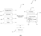
- FIG.1 shows a block diagram, illustrating different components of a system 100 to attenuate sound produced by a vehicle, in accordance with some embodiments of the present disclosure.
- the system 100 comprises an Electronic Control Unit (ECU) 104 , a navigation device 101 , a light sensor 105 , a timer 106 , a switch 114 , a microphone 112 , a memory unit 113 , and an exhaust assembly 103 employed with a sound reduction unit 102 and an actuator 111 .
- ECU Electronic Control Unit
- the components of the system 100 - the navigation device 101 , the light sensor 105 , the timer 106 , the switch 114 , the memory unit 113 , the microphone 112 , and the exhaust assembly 103 are interfaced with the ECU 104 to communicate data.
- the system of the present disclosure is configured to selectively attenuate sound produced by the vehicle by considering location, ambient conditions, and time information of the vehicle.
- the ECU 104 of the system 100 is configured to detect a sound reduction location based on inputs from the navigation device 101 , the light sensor 105 , the timer 106 , and the switch 114 .
- the sound reduction location is the location where sound of the vehicle is to be reduced to a particular level, and such location may include, but is not limited to, schools, hospitals, courts, residential areas, and tunnels.
- the navigation device 101 of the system 100 may be associated with the vehicle, and is configured to determine location details of the vehicle.
- a Global Positioning System GPS
- the navigation device 101 interfaced with the ECU 104 transmits the determined location details to the ECU 104 .
- the ECU 104 may determine a sound reduction location i.e. a location where sound produced by the vehicle is to be reduced, based on inputs from the navigation device 101 .
- the sound reduction location may be identified based on pre-defined location data stored in the memory unit 113 of the system 100 .
- the location determined by the navigation device 101 is compared with the pre-defined location data and when the determined location corresponds with at least one of the pre-defined location data, such a location may be identified as the sound reduction location.
- the pre-defined location data may include areas or locations such as, but not limited to, hospitals, schools, courts etc. Thus, when the vehicle approaches any of these pre-defined locations, the ECU 104 recognizes that sound produced by the vehicle is to be reduced.
- the system 100 also comprises a light sensor 105 provisioned in the vehicle.
- the light sensor 105 may be communicatively coupled to the ECU 104 , and is configured to sense a change in illumination level around the vehicle.
- the light sensor 105 used in the system 100 may be at least one of photo resistors, photodiodes, and phototransistors. In areas, such as tunnels, the sound produced by the vehicle tends to amplify and may echo which is undesirable. Thus, to detect and attenuate sound of the vehicle in such areas, the light sensors 105 may be employed in the system 100 .
- the light sensor 105 may detect change in illumination level of the light.
- the ECU 104 Based on inputs from the light sensor 105 and the navigation device 101 , the ECU 104 identifies such areas as a sound reduction location where sound of the vehicle is to be reduced. In an embodiment, such areas may be referred to as illumination-based sound reduction locations. It is to be understood that an illumination-based sound reduction location is identified by the ECU 104 based on inputs from the light sensor 105 as well as the navigation device 101 . The inputs from navigation device 101 ensure that the usage of vehicle in tunnels during night times are taken into consideration.
- the ECU 104 also receives inputs from the timer 106 to determine the current time of the vehicle.
- the memory unit 113 may comprise pre-defined time data indicating times at which sound is to be reduced or attenuated in selective areas such as, but not limited to, hospitals and residential areas.
- the ECU 104 may identify the sound reduction location based on the inputs from the timer 106 and the navigation device 101 , and such location or area may be referred to as a time-based sound reduction location.
- the time-based sound reduction location is identified by the ECU 104 when time determined by the timer 106 corresponds to at least one pre-defined time data stored in the memory unit 113 and based on the location determined by the navigation device 101 .
- the pre-defined time data may include time data as say, 11 PM to 6 AM for residential areas.
- the ECU 104 identifies such location as a time-based sound reduction location where sound is to be attenuated to required intensity. Similar time configurations may be pre-defined for other locations such as schools or courts, where sound level is expected to be minimal during day time interval.
- the system may include a switch 114 which may be manually operated to send signals to the ECU 104 to reduce sound produced by the vehicle according to the desire of the vehicle user.
- the ECU 104 of the vehicle is operatively coupled to the sound reduction unit 102 .
- the sound reduction unit 102 may be employed in the exhaust assembly 103 of the vehicle, and is configured to attenuate the sound produced by the vehicle to optimum pre-defined level.
- the sound reduction unit 102 comprises a plurality of sound filters 107 (as shown in FIG.2 ), and each of the sound filters of the plurality of sound filters 107 is configured to reduce sound to different levels according to the requirements.
- the ECU 104 is configured to operate the sound reduction unit 102 , such that at least one of the plurality of sound filters 107 may be aligned with an exhaust path of the exhaust assembly 103 to attenuate the sound produced by vehicle to required level. Thus, the sound produced by the vehicle is attenuated before the exhaust is let into the surrounding environment.
- the system 100 further comprises a microphone 112 positioned at an outlet of the exhaust assembly 103 of the vehicle.
- the microphone 112 is configured to measure the intensity of sound produced by the vehicle upon attenuation by the sound reduction unit 102 .
- the microphone 112 is to ensure that the sound intensity of the vehicle is reduced to required level.
- the desired sound intensity to which the vehicle is to be attenuated may be pre-defined and stored in the memory unit 113 .
- the ECU 104 which is communicatively coupled to the microphone 112 receives the corresponding signal of sound intensity measured by the microphone 112 after attenuation by the sound reduction unit 102 .
- the ECU 104 compares the measured sound intensity with the pre-defined sound intensity to which the vehicle sound is to be reduced.
- the ECU 104 Upon comparison, if the ECU 104 identifies that the measured intensity of sound is greater than the desired pre-defined sound intensity to which the vehicle is to be attenuated, the ECU 104 operates the sound reduction unit 102 again.
- the sound reduction unit 102 is configured to attenuate the sound produced by the vehicle to pre-defined sound intensity.
- FIG.2 illustrates a schematic view of the sound reduction unit 102 (as shown in FIG.2 ) employed in the exhaust assembly 103 in accordance with some embodiments of the present disclosure.
- the sound reduction unit 102 is used to attenuate sound produced by the vehicle.
- the sound reduction unit 102 is configured to attenuate sound produced by an engine E of the vehicle.
- the ECU 104 operates the sound reduction unit 102 to attenuate sound produced by the vehicle, particularly engine E of the vehicle based on the inputs received from at least one of the navigation device 101 , the light sensor 105 , the timer 106 , and the manually operated switch 114 .
- the sound reduction unit 102 is configured in the exhaust assembly 103 of the vehicle.
- the sound reduction unit 102 is configured to reduce the sound before letting the exhaust into the surrounding environment.
- the sound reduction unit 102 comprises a plurality of sound filters 107 to attenuate the sound of the vehicle to required level.
- the plurality of sound filters 107 are arranged in a polar array, wherein each sound filter 107 is configured to attenuate sound intensity to a different level.
- each sound filter 107 may have a different rating to reduce the sound intensity.
- the sound reduction unit 102 comprises a support member 109 which further comprises a plurality of provisions 110 (as shown in FIG.3 ) to accommodate the plurality of sound filters 107 .
- the support member 109 is rotatably mounted on a shaft 109a provisioned in the exhaust assembly 103 .
- the sound reduction unit 102 also comprises an actuator 111 to impart rotational motion to the support member 109 .
- the actuator 111 may be at least one of a hydraulic, a pneumatic, an electric, or a mechanical actuator to impart rotary motion to the support member 109 .
- the support member 109 may be selectively driven by the actuator 111 through a drive means 115 which imparts rotary motion to the support member 109 .
- the drive means 115 used to drive the support member 109 may include a belt pulley drive, a chain drive, and/or a gear drive mechanism.
- the belt drive means 115 is used to drive the support member 109 by the actuator 111 .
- a shaft 109b of the actuator 111 is connected to the pulley to which rotary motion is transmitted.
- the pulley further transmits rotary motion to the support member 109 through the belt.
- usage of belt pulley drive means 115 to impart rotary motion to the support member 109 should not be construed as a limitation to the present disclosure, as any other suitable drive means may be used.
- the ECU 104 is configured to determine the sound intensity to which the vehicle is to be reduced based on the inputs, and operates the sound reduction unit 102 to align appropriate sound filter of the plurality of sound filters 107 with the exhaust path 108 to attenuate sound.
- the ECU operates the actuator 111 to align suitable sound filter of the plurality of sound filters with the exhaust path 108 to attenuate sound. For example, considering that there are four sound filters 107 in the sound reduction unit 102 rated 50 decibels (dB), 60dB, 70dB and 80dB and the ECU 104 determines that the sound level to which the vehicle is to be attenuated is 60dB.
- the ECU 104 operates the sound reduction unit 102 based on the determined value so as to align the sound filter rated 60dB with the exhaust path 108 and thus attenuating the sound of the vehicle to required level.
- FIG.3 which illustrates sectional front view of the sound reduction unit 102 .
- the sound reduction unit 102 comprises a position detector 107a proximal to the exhaust path 108 .
- the position detector 107a is configured to detect the position of the sound filters 107 with respect to the exhaust path 108 .
- the position detector 107a is interfaced with the ECU 104 and communicates the position details of the sound filter 107 .
- the ECU 104 is configured to regulate the actuator 111 to enable proper alignment of the appropriate sound filter 107 with the exhaust path 108 to attenuate sound.
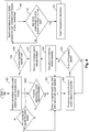
- FIG.4 illustrates a flowchart showing a method to attenuate sound produced by the vehicle in accordance with some embodiments of the present disclosure.
- the method comprises one or more blocks explaining an exemplary method in which the system 100 may be operated to attenuate the sound produced by the vehicle.
- the method may be described in the general context of computer executable instructions.
- computer executable instructions can include routines, programs, objects, components, data structures, procedures, modules, and functions, which may perform particular functions or implement particular abstract data types.
- the ECU 104 of the system 100 receives inputs from a plurality of associated components.
- the ECU 104 is associated with the navigation device 101 which is configured to determine location details of the vehicle.
- the ECU 104 then receives inputs regarding the location details of the vehicle through the navigation device 101 .
- the ECU 104 also receives inputs regarding changes in illumination level through the light sensor 105 associated with the ECU 104 .
- the ECU 104 receives time information from the timer 106 regarding current or instant time.
- the ECU 104 checks if there is a manual input from the user through switch 114 to attenuate sound produced by the vehicle. Further, the ECU 104 based on the inputs received from the navigation device 101 , the light sensor 105 , the timer 106 and the switch 114 , identifies sound reduction location. In an embodiment, the sound reduction location may be identified by the when the location details from the navigation device 101 correspond to pre-defined location data stored in the memory unit 113 . Further, the sound reduction location may also be based on changes in illumination level around the vehicle, which is referred to as illumination based sound reduction location.
- the illumination based sound reduction location is determined by the ECU 104 when the illumination level sensed by the light sensor 105 around the vehicle is below threshold illumination and based on location details from the navigation device 101 . Further, the sound reduction location may also be based on time information from the timer 106 . The ECU 104 identifies a particular location as time based sound reduction location if the time information from the timer corresponds to pre-defined time. The time-based sound reduction location also depends on location of the vehicle.
- the ECU 104 determines the sound intensity level to which the vehicle is to be brought upon identifying the sound reduction location, and accordingly operates the sound reduction unit 102 to attenuate sound produced by the vehicle.
- the sound reduction unit 102 is positioned in the exhaust assembly 103 of the vehicle.
- the sound is attenuated through a plurality of sound filters 107 provisioned in the support member 109 of the sound reduction unit 102 .
- the support member 109 is rotatably mounted in the exhaust assembly 103 and is driven by actuator 111 .
- appropriate sound filter 107 may be aligned with the exhaust path 108 of the exhaust assembly.
- sound filter 107 attenuates the sound of the vehicle in the exhaust path 108 , before letting exhaust to the surrounding environment.
- the ECU 104 analyzes the position of the sound filter 107 based on data received from the position detector 107a .
- the position detector 107a ensures that an appropriate sound filter 107 is aligned properly with the exhaust path 108 to attenuate sound of the vehicle. Subsequently, the ECU 104 performs a check at block 405 , if the sound filter 107 is aligned with the exhaust path 108 of the exhaust assembly 103 .
- the ECU 104 halts the operation of actuator 111 .
- the microphone 112 which is positioned at outlet of the exhaust path 108 measures the sound intensity upon sound attenuation by the sound reduction unit 102 .
- the microphone 112 is associated with the ECU 104 and communicates the measured intensity of sound by the microphone 112 to the ECU 104 . Further, at block 408 , the ECU 104 checks if the sound is regulated to the required pre-defined level.
- the sound reduction unit 102 is activated again and steps explained in blocks 403 to 406 may be repeated to further reduce the sound of the vehicle to required level.
- the ECU 104 checks if there is any manual input through switch 114 or receives and analyzes inputs from the navigation device 101 , the light sensor 105 , the timer 106 or manual operation of the switch 114 . The ECU 104 analyzes and identifies the location as shown in block 410 .
- the ECU 104 operates the sound reduction unit 102 as shown in block 411 to reset the filtering level to default level, thus allowing normal operation of the vehicle without any sound attenuation.
- the system 100 may use ECU 104 of the vehicle or a dedicated control unit.
- the Control unit may include specialized processing units such as integrated system (bus) controllers, memory management control units, floating point units, graphics processing units, digital signal processing units, etc.
- the processing unit may include a microprocessor, such as AMD Athlon, Duron or Opteron, ARM's application, embedded or secure processors, IBM PowerPC, Intel's Core, Itanium, Xeon, Celeron or other line of processors, etc.
- the control unit may be implemented using mainframe, distributed processor, multi-core, parallel, grid, or other architectures. Some embodiments may utilize embedded technologies like application-specific integrated circuits (ASICs), digital signal processors (DSPs), Field Programmable Gate Arrays (FPGAs), microcontroller, etc.
- ASICs application-specific integrated circuits
- DSPs digital signal processors
- FPGAs Field Programmable Gate Arrays
- control unit may be disposed in communication with one or more memory devices (e.g., RAM, ROM etc.) via a storage interface.
- the storage interface may connect to memory devices including, without limitation, memory drives, removable disc drives, etc., employing connection protocols such as serial advanced technology attachment (SATA), integrated drive electronics (IDE), IEEE-1394, universal serial bus (USB), fiber channel, small computing system interface (SCSI), etc.
- the memory drives may further include a drum, magnetic disc drive, magneto-optical drive, optical drive, redundant array of independent discs (RAID), solid-state memory devices, solid-state drives, etc.
- the present disclosure discloses a system to attenuate sound produced by the vehicle depending on the location of the vehicle.
- the system also takes into consideration illumination level changes around the vehicle and time information to attenuate sound produced by the vehicle.
Landscapes
- Engineering & Computer Science (AREA)
- Mechanical Engineering (AREA)
- Chemical & Material Sciences (AREA)
- Combustion & Propulsion (AREA)
- General Engineering & Computer Science (AREA)
- Physics & Mathematics (AREA)
- General Physics & Mathematics (AREA)
- Spectroscopy & Molecular Physics (AREA)
- Acoustics & Sound (AREA)
- Multimedia (AREA)
- Soundproofing, Sound Blocking, And Sound Damping (AREA)
- Navigation (AREA)
- Fittings On The Vehicle Exterior For Carrying Loads, And Devices For Holding Or Mounting Articles (AREA)
Abstract
Description
- The present disclosure generally relates to the field of automobiles. Particularly, but not exclusively the present disclosure relates to exhaust assembly of a vehicle. Further embodiments of the present disclosure disclose a system employed in the exhaust assembly for attenuating sound produced by the vehicle.
- As population continues to grow, the number of vehicles being used on the roads is also increasing. Due to the increase in the number of vehicles, the problems associated with vehicles, such as vehicle emissions, have also increased substantially. In many areas, certain environmental restrictions have been imposed to control vehicle emissions. Also, in some of the places, laws and regulations have been implemented to control speed at which people drive, and vehicle fuel efficiency, as well as the emissions produced by vehicles.
- One of the common vehicular emission problems may include the noise or sound generated by the vehicle. The noise generated by the vehicles may be disturbing and may pose other repercussions. For instance, elevated sound levels may cause health issues, including hearing impairment, hypertension, and sleep disturbance. Some birth defects have also been linked to excessive exposure to noise. However, very little attention has been given to address noise pollution produced by vehicles on the roads. To maintain orderly and responsible vehicle operation, there exists a need to deter excessive noise emission from the vehicles.
- Considering the above, various types of silencers and exhaust systems have been developed. These silencers aim to curb sound or noise produced by the vehicle with improvements in the effectiveness of the silencer over other known silencers.
- However, some vehicles, such as sport utility vehicles and cruiser vehicles are tuned to generate a loud engine noise to provide a good riding or driving sensation for the users. Hence, the sound attenuating silencers are not put into use in such vehicles. On the other hand, the sound produced by such vehicles may be problematic to the general public. Particularly, at some locations or sensitive areas including, but not limited to, schools, courts, hospitals, religious establishments, etc., vehicles producing high engine noise may cause disturbance and are undesirable.
- In some of the conventional developments, techniques for detecting the vehicle entering a geo-fenced area have been developed. In such technique, the user of the vehicle may be alerted about the drive requirements in such areas, and may control different driving parameters when the geo-fenced area is determined. Although location and surrounding conditions of the vehicle are taken into consideration, and various drive parameters are controlled depending on the location, the parameter of reducing the sound or noise of the vehicle is not taken into consideration by the conventional techniques.
- The present disclosure is directed to overcome one or more limitations stated above.
- One or more shortcomings of the conventional systems to attenuate the sound produced by the vehicle are overcome and additional advantages are provided through the present disclosure. Additional features and advantages are realized through the techniques of the present disclosure. Other embodiments and aspects of the disclosure are described in detail herein and are considered a part of the claimed disclosure.
- In a non-limiting embodiment of the disclosure, a system for attenuating the sound produced by a vehicle is disclosed. The system comprises a navigation device associated with the vehicle for determining location details of the vehicle, and a sound reduction unit provisioned in an exhaust assembly of the vehicle. The system further includes an Electronic Control Unit (ECU) of the vehicle communicatively coupled to the navigation device and the sound reduction unit. The ECU is configured to detect a sound reduction location by comparing the location details with a pre-defined location data, and to operate the sound reduction unit to attenuate the sound produced by the vehicle when the sound reduction location is detected.
- In another non-limiting embodiment of the disclosure, a method for attenuating the sound produced by a vehicle is disclosed. The method firstly comprises an act of determining, by a navigation device, location details of the vehicle. The method further comprises acts of detecting, by the Electronic Control Unit (ECU), sound reduction location by comparing the location details with a pre-defined location data and operating, by the ECU, the sound reduction unit to attenuate the sound produced by the vehicle when the sound reduction location is detected.
- In another embodiment, a non-transitory computer-readable storage medium for attenuating sound produced by a vehicle is disclosed which, when executed by a computing device, cause the computing device to perform operations including, determining location details of the vehicle. The operations further include detecting a sound reduction location by comparing the location details with a pre-defined location data. Finally, the operations include operating a sound reduction unit to attenuate sound produced by the vehicle when the sound reduction location is detected.
- The foregoing summary is illustrative only and is not intended to be in any way limiting. In addition to the illustrative aspects, embodiments, and features described above, further aspects, embodiments, and features will become apparent by reference to the drawings and the following detailed description.
- The accompanying drawings, which are incorporated in and constitute a part of this disclosure, illustrate exemplary embodiments and, together with the description, serve to explain the disclosed principles. The same numbers are used throughout the figures to reference like features and components. Some embodiments of device and/or methods in accordance with embodiments of the present subject matter are now described, by way of example only, and with reference to the accompanying figures, in which:
-
FIG.1 shows a block diagram of a system for attenuating sound produced by vehicle, in accordance with some embodiments of the present disclosure; -
FIG.2 illustrates schematic representation of vehicle exhaust assembly comprising asound reduction unit to attenuate sound produced by the engine of the vehicle, in accordance with some embodiments of the present disclosure; -
FIG.3 illustrates schematic front view of the sound reduction unit ofFIG.2 , in accordance with some embodiments of the present disclosure; and -
FIG.4 illustrates a flowchart showing a method to attenuate sound produced by the vehicle in accordance with some embodiments of the present disclosure. - It should be appreciated by those skilled in the art that any block diagrams herein represent conceptual views of illustrative device embodying the principles of the present subject matter. Similarly, it will be appreciated that any flow charts, flow diagrams, state transition diagrams, and the like represent various processes which may be substantially represented in computer readable medium and executed by a computer or processor, whether or not such computer or processor is explicitly shown.
- While the disclosure is susceptible to various modifications and alternative forms, specific embodiment thereof has been shown by way of example in the drawings and will be described in detail below. It should be understood, however that it is not intended to limit the disclosure to the particular forms disclosed, but on the contrary, the disclosure is to cover all modifications, equivalents, and alternative falling within the scope of the disclosure.
- Embodiments of the disclosure disclose a system to attenuate sound produced by the vehicle. The system attenuates the sound of the vehicle taking the surrounding conditions of the vehicle into consideration. The provision of such system in the vehicle allows attenuation of sound selectively in restricted or sensitive locations and normal operation of the vehicle without any attenuation of sound in unrestricted locations.
- The system to attenuate sound produced by the vehicle comprises an Electronic Control Unit (ECU) of the vehicle. The ECU may be communicatively interfaced to a number of devices and components associated with the vehicle. The system includes a navigation device to determine location details of the vehicle. In an embodiment, the navigation device may be a Global Positioning System (GPS) which is associated with the vehicle. The navigation device is interfaced with the ECU, and the ECU may receive inputs from the navigation device and identifies a sound reduction location. A particular location may be identified as the sound reduction location by the ECU when the location determined by the navigation device corresponds with at least one location in the pre-defined location data. In an embodiment, the pre-defined location data may be stored in a memory unit associated with the ECU. In one embodiment, the pre-defined location data where sound is to be attenuated, may include locations such as, but not limited to, hospitals, schools, courts, and residential areas. In some embodiments, the sound reduction location may also be identified by the ECU based on signals received from a light sensor and/or the timer associated with the vehicle.
- The system further comprises a sound reduction unit employed in an exhaust assembly of the vehicle. The sound reduction unit is operatively coupled to the ECU and is configured to attenuate sound to the required level. The sound reduction unit comprises a plurality of sound filters, and each of the plurality of sound filters may be configured to attenuate sound to a different level as per the requirement. The ECU is configured to operate the sound reduction unit, such that at least one of the plurality of sound filters may be aligned with an exhaust path of the exhaust assembly to attenuate the sound produced by vehicle to required level.
- Further, the system comprises a microphone provisioned at an outlet of the exhaust path. The microphone may be configured to measure the intensity of sound once the sound is attenuated selectively by the at least one sound filter. The microphone is communicatively coupled to the ECU and transmits the measured intensity of sound to the ECU. The ECU is further configured to compare the intensity of the sound measured by the microphone with a pre-defined sound data, and regulates the sound reduction unit based on the comparison. In an embodiment, the sound reduction unit is regulated to further attenuate sound if the measured intensity of sound by the microphone is greater than a pre-defined sound intensity stored in the memory unit.
- In the following detailed description, embodiments of the disclosure are explained with reference of accompanying figures that form a part hereof, and in which are shown by way of illustration specific embodiments in which the disclosure may be practiced. These embodiments are described in sufficient detail to enable those skilled in the art to practice the disclosure, and it is to be understood that other embodiments may be utilized and that changes may be made without departing from the scope of the present disclosure. The following description is, therefore, not to be taken in a limiting sense.
-
FIG.1 shows a block diagram, illustrating different components of asystem 100 to attenuate sound produced by a vehicle, in accordance with some embodiments of the present disclosure. - In an exemplary implementation, as shown in
FIG.1 , thesystem 100 comprises an Electronic Control Unit (ECU) 104, anavigation device 101, alight sensor 105, atimer 106, aswitch 114, amicrophone 112, amemory unit 113, and anexhaust assembly 103 employed with asound reduction unit 102 and anactuator 111. - As shown in
FIG.1 , the components of the system 100 - thenavigation device 101, thelight sensor 105, thetimer 106, theswitch 114, thememory unit 113, themicrophone 112, and theexhaust assembly 103 are interfaced with theECU 104 to communicate data. - The system of the present disclosure is configured to selectively attenuate sound produced by the vehicle by considering location, ambient conditions, and time information of the vehicle.
- The
ECU 104 of thesystem 100 is configured to detect a sound reduction location based on inputs from thenavigation device 101, thelight sensor 105, thetimer 106, and theswitch 114. The sound reduction location is the location where sound of the vehicle is to be reduced to a particular level, and such location may include, but is not limited to, schools, hospitals, courts, residential areas, and tunnels. - The
navigation device 101 of thesystem 100 may be associated with the vehicle, and is configured to determine location details of the vehicle. In an embodiment, a Global Positioning System (GPS) may be used to determine location details of the vehicle. Thenavigation device 101 interfaced with theECU 104 transmits the determined location details to theECU 104. TheECU 104 may determine a sound reduction location i.e. a location where sound produced by the vehicle is to be reduced, based on inputs from thenavigation device 101. The sound reduction location may be identified based on pre-defined location data stored in thememory unit 113 of thesystem 100. The location determined by thenavigation device 101 is compared with the pre-defined location data and when the determined location corresponds with at least one of the pre-defined location data, such a location may be identified as the sound reduction location. In an embodiment, the pre-defined location data may include areas or locations such as, but not limited to, hospitals, schools, courts etc. Thus, when the vehicle approaches any of these pre-defined locations, theECU 104 recognizes that sound produced by the vehicle is to be reduced. - The
system 100 also comprises alight sensor 105 provisioned in the vehicle. Thelight sensor 105 may be communicatively coupled to theECU 104, and is configured to sense a change in illumination level around the vehicle. In an embodiment, thelight sensor 105 used in thesystem 100 may be at least one of photo resistors, photodiodes, and phototransistors. In areas, such as tunnels, the sound produced by the vehicle tends to amplify and may echo which is undesirable. Thus, to detect and attenuate sound of the vehicle in such areas, thelight sensors 105 may be employed in thesystem 100. Thelight sensor 105 may detect change in illumination level of the light. Based on inputs from thelight sensor 105 and thenavigation device 101, theECU 104 identifies such areas as a sound reduction location where sound of the vehicle is to be reduced. In an embodiment, such areas may be referred to as illumination-based sound reduction locations. It is to be understood that an illumination-based sound reduction location is identified by theECU 104 based on inputs from thelight sensor 105 as well as thenavigation device 101. The inputs fromnavigation device 101 ensure that the usage of vehicle in tunnels during night times are taken into consideration. - Further, the
ECU 104 also receives inputs from thetimer 106 to determine the current time of the vehicle. In an embodiment, thememory unit 113 may comprise pre-defined time data indicating times at which sound is to be reduced or attenuated in selective areas such as, but not limited to, hospitals and residential areas. In an embodiment, theECU 104, may identify the sound reduction location based on the inputs from thetimer 106 and thenavigation device 101, and such location or area may be referred to as a time-based sound reduction location. The time-based sound reduction location is identified by theECU 104 when time determined by thetimer 106 corresponds to at least one pre-defined time data stored in thememory unit 113 and based on the location determined by thenavigation device 101. For instance, in locations such as residential areas, it is expected to maintain a minimal sound level during night times. The pre-defined time data may include time data as say, 11 PM to 6 AM for residential areas. Thus, when the vehicle approaches residential areas during above mentioned time interval, theECU 104 identifies such location as a time-based sound reduction location where sound is to be attenuated to required intensity. Similar time configurations may be pre-defined for other locations such as schools or courts, where sound level is expected to be minimal during day time interval. In some embodiments, the system may include aswitch 114 which may be manually operated to send signals to theECU 104 to reduce sound produced by the vehicle according to the desire of the vehicle user. - The
ECU 104 of the vehicle is operatively coupled to thesound reduction unit 102. Thesound reduction unit 102 may be employed in theexhaust assembly 103 of the vehicle, and is configured to attenuate the sound produced by the vehicle to optimum pre-defined level. Thesound reduction unit 102 comprises a plurality of sound filters 107 (as shown inFIG.2 ), and each of the sound filters of the plurality of sound filters 107 is configured to reduce sound to different levels according to the requirements. TheECU 104 is configured to operate thesound reduction unit 102, such that at least one of the plurality ofsound filters 107 may be aligned with an exhaust path of theexhaust assembly 103 to attenuate the sound produced by vehicle to required level. Thus, the sound produced by the vehicle is attenuated before the exhaust is let into the surrounding environment. - The
system 100 further comprises amicrophone 112 positioned at an outlet of theexhaust assembly 103 of the vehicle. Themicrophone 112 is configured to measure the intensity of sound produced by the vehicle upon attenuation by thesound reduction unit 102. Themicrophone 112 is to ensure that the sound intensity of the vehicle is reduced to required level. In an embodiment, the desired sound intensity to which the vehicle is to be attenuated may be pre-defined and stored in thememory unit 113. TheECU 104 which is communicatively coupled to themicrophone 112 receives the corresponding signal of sound intensity measured by themicrophone 112 after attenuation by thesound reduction unit 102. TheECU 104 then compares the measured sound intensity with the pre-defined sound intensity to which the vehicle sound is to be reduced. Upon comparison, if theECU 104 identifies that the measured intensity of sound is greater than the desired pre-defined sound intensity to which the vehicle is to be attenuated, theECU 104 operates thesound reduction unit 102 again. In an embodiment, thesound reduction unit 102 is configured to attenuate the sound produced by the vehicle to pre-defined sound intensity. - Referring now to
FIG.2 which illustrates a schematic view of the sound reduction unit 102 (as shown inFIG.2 ) employed in theexhaust assembly 103 in accordance with some embodiments of the present disclosure. Thesound reduction unit 102 is used to attenuate sound produced by the vehicle. In an exemplary embodiment as shown inFIG.2 , thesound reduction unit 102 is configured to attenuate sound produced by an engine E of the vehicle. As described in foregoing paragraphs, theECU 104 operates thesound reduction unit 102 to attenuate sound produced by the vehicle, particularly engine E of the vehicle based on the inputs received from at least one of thenavigation device 101, thelight sensor 105, thetimer 106, and the manually operatedswitch 114. As shown inFIG.2 , thesound reduction unit 102 is configured in theexhaust assembly 103 of the vehicle. Thesound reduction unit 102 is configured to reduce the sound before letting the exhaust into the surrounding environment. - The
sound reduction unit 102 comprises a plurality ofsound filters 107 to attenuate the sound of the vehicle to required level. In an embodiment, the plurality ofsound filters 107 are arranged in a polar array, wherein eachsound filter 107 is configured to attenuate sound intensity to a different level. Thus, eachsound filter 107 may have a different rating to reduce the sound intensity. In one embodiment, thesound reduction unit 102 comprises asupport member 109 which further comprises a plurality of provisions 110 (as shown inFIG.3 ) to accommodate the plurality of sound filters 107. Thesupport member 109 is rotatably mounted on ashaft 109a provisioned in theexhaust assembly 103. Thesound reduction unit 102 also comprises anactuator 111 to impart rotational motion to thesupport member 109. Theactuator 111 may be at least one of a hydraulic, a pneumatic, an electric, or a mechanical actuator to impart rotary motion to thesupport member 109. Thesupport member 109 may be selectively driven by theactuator 111 through a drive means 115 which imparts rotary motion to thesupport member 109. In an embodiment, the drive means 115 used to drive thesupport member 109 may include a belt pulley drive, a chain drive, and/or a gear drive mechanism. - In an exemplary embodiment, the belt drive means 115 is used to drive the
support member 109 by theactuator 111. In operation, ashaft 109b of theactuator 111 is connected to the pulley to which rotary motion is transmitted. The pulley further transmits rotary motion to thesupport member 109 through the belt. However, usage of belt pulley drive means 115 to impart rotary motion to thesupport member 109 should not be construed as a limitation to the present disclosure, as any other suitable drive means may be used. - The
ECU 104 is configured to determine the sound intensity to which the vehicle is to be reduced based on the inputs, and operates thesound reduction unit 102 to align appropriate sound filter of the plurality ofsound filters 107 with theexhaust path 108 to attenuate sound. In an embodiment of the disclosure, the ECU operates theactuator 111 to align suitable sound filter of the plurality of sound filters with theexhaust path 108 to attenuate sound. For example, considering that there are foursound filters 107 in thesound reduction unit 102 rated 50 decibels (dB), 60dB, 70dB and 80dB and theECU 104 determines that the sound level to which the vehicle is to be attenuated is 60dB. TheECU 104 operates thesound reduction unit 102 based on the determined value so as to align the sound filter rated 60dB with theexhaust path 108 and thus attenuating the sound of the vehicle to required level. Now referring toFIG.3 which illustrates sectional front view of thesound reduction unit 102. Thesound reduction unit 102 comprises aposition detector 107a proximal to theexhaust path 108. Theposition detector 107a is configured to detect the position of the sound filters 107 with respect to theexhaust path 108. Theposition detector 107a is interfaced with theECU 104 and communicates the position details of thesound filter 107. TheECU 104 is configured to regulate theactuator 111 to enable proper alignment of theappropriate sound filter 107 with theexhaust path 108 to attenuate sound. -
FIG.4 illustrates a flowchart showing a method to attenuate sound produced by the vehicle in accordance with some embodiments of the present disclosure. - As illustrated in
FIG.4 , the method comprises one or more blocks explaining an exemplary method in which thesystem 100 may be operated to attenuate the sound produced by the vehicle. The method may be described in the general context of computer executable instructions. - Generally, computer executable instructions can include routines, programs, objects, components, data structures, procedures, modules, and functions, which may perform particular functions or implement particular abstract data types.
- The order in which the method is described is not intended to be construed as a limitation, and any number of the described method blocks can be combined in any order to implement the method. Additionally, individual blocks may be deleted from the methods without departing from the scope of the subject matter described herein. Furthermore, the method can be implemented in any suitable hardware, software, firmware, or combination thereof.
- At
block 401, theECU 104 of thesystem 100 receives inputs from a plurality of associated components. TheECU 104 is associated with thenavigation device 101 which is configured to determine location details of the vehicle. TheECU 104 then receives inputs regarding the location details of the vehicle through thenavigation device 101. Further, theECU 104 also receives inputs regarding changes in illumination level through thelight sensor 105 associated with theECU 104. In addition to inputs from thenavigation device 101 and thelight sensor 105, theECU 104 receives time information from thetimer 106 regarding current or instant time. - At
blocks 402, theECU 104 checks if there is a manual input from the user throughswitch 114 to attenuate sound produced by the vehicle. Further, theECU 104 based on the inputs received from thenavigation device 101, thelight sensor 105, thetimer 106 and theswitch 114, identifies sound reduction location. In an embodiment, the sound reduction location may be identified by the when the location details from thenavigation device 101 correspond to pre-defined location data stored in thememory unit 113. Further, the sound reduction location may also be based on changes in illumination level around the vehicle, which is referred to as illumination based sound reduction location. In an embodiment, the illumination based sound reduction location is determined by theECU 104 when the illumination level sensed by thelight sensor 105 around the vehicle is below threshold illumination and based on location details from thenavigation device 101. Further, the sound reduction location may also be based on time information from thetimer 106. TheECU 104 identifies a particular location as time based sound reduction location if the time information from the timer corresponds to pre-defined time. The time-based sound reduction location also depends on location of the vehicle. - At
block 403, theECU 104 determines the sound intensity level to which the vehicle is to be brought upon identifying the sound reduction location, and accordingly operates thesound reduction unit 102 to attenuate sound produced by the vehicle. In an embodiment, thesound reduction unit 102 is positioned in theexhaust assembly 103 of the vehicle. The sound is attenuated through a plurality ofsound filters 107 provisioned in thesupport member 109 of thesound reduction unit 102. Thesupport member 109 is rotatably mounted in theexhaust assembly 103 and is driven byactuator 111. As per the determined regulation level of sound,appropriate sound filter 107 may be aligned with theexhaust path 108 of the exhaust assembly. Thus,sound filter 107 attenuates the sound of the vehicle in theexhaust path 108, before letting exhaust to the surrounding environment. - At
block 404, theECU 104 analyzes the position of thesound filter 107 based on data received from theposition detector 107a. Theposition detector 107a ensures that anappropriate sound filter 107 is aligned properly with theexhaust path 108 to attenuate sound of the vehicle. Subsequently, theECU 104 performs a check atblock 405, if thesound filter 107 is aligned with theexhaust path 108 of theexhaust assembly 103. - At
block 406, once thesound filter 107 is aligned appropriately, theECU 104 halts the operation ofactuator 111. - At
block 407, themicrophone 112 which is positioned at outlet of theexhaust path 108 measures the sound intensity upon sound attenuation by thesound reduction unit 102. Themicrophone 112 is associated with theECU 104 and communicates the measured intensity of sound by themicrophone 112 to theECU 104. Further, atblock 408, theECU 104 checks if the sound is regulated to the required pre-defined level. - If the sound is not regulated to the required level, the
sound reduction unit 102 is activated again and steps explained inblocks 403 to 406 may be repeated to further reduce the sound of the vehicle to required level. Atblock 409 if sound is regulated to the required level, theECU 104 checks if there is any manual input throughswitch 114 or receives and analyzes inputs from thenavigation device 101, thelight sensor 105, thetimer 106 or manual operation of theswitch 114. TheECU 104 analyzes and identifies the location as shown inblock 410. If the location is not identified as sound reduction location or the input signal from the manual switch has been received as shown inblock 410, theECU 104 operates thesound reduction unit 102 as shown inblock 411 to reset the filtering level to default level, thus allowing normal operation of the vehicle without any sound attenuation. - In an embodiment of the disclosure, the
system 100 may useECU 104 of the vehicle or a dedicated control unit. The Control unit may include specialized processing units such as integrated system (bus) controllers, memory management control units, floating point units, graphics processing units, digital signal processing units, etc. The processing unit may include a microprocessor, such as AMD Athlon, Duron or Opteron, ARM's application, embedded or secure processors, IBM PowerPC, Intel's Core, Itanium, Xeon, Celeron or other line of processors, etc. The control unit may be implemented using mainframe, distributed processor, multi-core, parallel, grid, or other architectures. Some embodiments may utilize embedded technologies like application-specific integrated circuits (ASICs), digital signal processors (DSPs), Field Programmable Gate Arrays (FPGAs), microcontroller, etc. - In some embodiments, the control unit may be disposed in communication with one or more memory devices (e.g., RAM, ROM etc.) via a storage interface. The storage interface may connect to memory devices including, without limitation, memory drives, removable disc drives, etc., employing connection protocols such as serial advanced technology attachment (SATA), integrated drive electronics (IDE), IEEE-1394, universal serial bus (USB), fiber channel, small computing system interface (SCSI), etc. The memory drives may further include a drum, magnetic disc drive, magneto-optical drive, optical drive, redundant array of independent discs (RAID), solid-state memory devices, solid-state drives, etc.
- Advantages of the embodiment of the present disclosure are illustrated herein.
- In an embodiment, the present disclosure discloses a system to attenuate sound produced by the vehicle depending on the location of the vehicle.
- In an embodiment, the system also takes into consideration illumination level changes around the vehicle and time information to attenuate sound produced by the vehicle.
- A description of an embodiment with several components in communication with each other does not imply that all such components are required. On the contrary a variety of optional components are described to illustrate the wide variety of possible embodiments of the invention.
- When a single device or article is described herein, it will be readily apparent that more than one device/article (whether or not they cooperate) may be used in place of a single device/article. Similarly, where more than one device or article is described herein (whether or not they cooperate), it will be readily apparent that a single device/article may be used in place of the more than one device or article or a different number of devices/articles may be used instead of the shown number of devices or programs. The functionality and/or the features of a device may be alternatively embodied by one or more other devices which are not explicitly described as having such functionality/features. Thus, other embodiments of the invention need not include the device itself.
- Finally, the language used in the specification has been principally selected for readability and instructional purposes. The scope of the invention is to be limited only by the claims. Accordingly, the embodiments of the present invention are intended to be illustrative, but not limiting, of the scope of the invention, which is set forth in the following claims.
- While various aspects and embodiments have been disclosed herein, other aspects and embodiments will be apparent to those skilled in the art. The various aspects and embodiments disclosed herein are for purposes of illustration and are not intended to be limiting, with the true scope being indicated by the following claims.
Claims (14)
- A system for attenuating sound produced by a vehicle, the system comprising:a navigation device associated with the vehicle for determining location details of the vehicle;a sound reduction unit provisioned in an exhaust assembly of the vehicle; andan Electronic Control Unit (ECU) of the vehicle communicatively coupled to the navigation device and the sound reduction unit, the ECU being configured to:detect a sound reduction location, by comparing the location details with a pre-defined location data; andoperate the sound reduction unit, to attenuate sound produced by the vehicle when the sound reduction location is detected.
- The system as claimed in claim 1, wherein a location is identified as the sound reduction location when the determined location corresponds with at least one location in the pre-defined location data.
- The system as claimed in claim 2, wherein a location is identified as the sound reduction location when there is a change in illumination level of light around the vehicle beyond a pre-defined threshold illumination level; the system optionally further comprising a light sensor mounted on the vehicle and communicatively coupled with the ECU, wherein the light sensor is configured to sense change in the illumination level of light around the vehicle.
- The system as claimed in claim 1, 2, or 3, wherein a location is identified as the sound reduction location based on a pre-defined time.
- The system as claimed in any preceding claim, further comprising a timer communicatively coupled with the ECU to determine current time.
- The system as claimed in any preceding claim, wherein the sound reduction unit comprises a plurality of sound filters rotatably mounted in the exhaust assembly of the vehicle; optionally wherein each of the plurality of sound filters is configured to attenuate sound to different levels; and further optionally wherein the ECU is configured to selectively align at least one sound filter of the plurality of sound filters with exhaust path in the exhaust assembly.
- The system as claimed in claim 6, wherein the sound reduction unit further comprises:a support member comprising a plurality of provisions, rotatably mounted in the exhaust assembly, wherein, each of the plurality of the provisions is configured to accommodate at least one sound filter of the plurality of sound filters; andan actuator coupled to the support member, wherein the actuator is operable by the ECU, to rotate the support member.
- The system as claimed in any preceding claim, further comprising a microphone communicatively coupled with the ECU, the microphone being positioned at an outlet portion of the exhaust path to measure intensity of sound at the outlet of the exhaust path; and optionally wherein the ECU is configured to:compare, the intensity of sound measured by the microphone with a pre-defined sound data; andregulate, the sound reduction unit based on the comparison.
- A method for attenuating sound produced by a vehicle, the method comprising:determining, by a navigation device, location details of the vehicle;detecting, by an Electronic Control Unit (ECU), a sound reduction location, by comparing the location details with a pre-defined location data; andoperating, by the ECU, a sound reduction unit to attenuate sound produced by the vehicle when the sound reduction location is detected.
- The method as claimed in claim 9, further comprising:sensing, by a light sensor, change in illumination level of light around the vehicle;identifying, by the ECU, the sound reduction location based on at least one of the change in the illumination level beyond a pre-defined threshold illumination level and when the determined location details corresponds with at least one location in the pre-defined location data.
- The method as claimed in claim 9 or 10, further comprising:determining, by the ECU, time information from a timer;identifying, by the ECU, the sound reduction location based on the time information corresponding to a pre-defined time and when the determined location details corresponds with at least one location in the pre-defined location data.
- The method as claimed in claim 9, 10, or 11, further comprising:measuring, by a microphone, intensity of sound at outlet of an exhaust path;comparing, by the ECU, the intensity of sound measured by the microphone with a pre-defined sound data; andregulating, by the ECU, the sound reduction unit based on the comparison.
- A vehicle comprising a system as claimed in any of claims 1 - 8.
- A non-transitory computer-readable medium storing instructions for attenuating sound produced by a vehicle, wherein upon execution of the instructions by one or more processors, the processors perform operations comprising the method of any of claims 9 - 12.
Applications Claiming Priority (1)
| Application Number | Priority Date | Filing Date | Title |
|---|---|---|---|
| IN201741002353 | 2017-01-20 |
Publications (2)
| Publication Number | Publication Date |
|---|---|
| EP3351757A1 true EP3351757A1 (en) | 2018-07-25 |
| EP3351757B1 EP3351757B1 (en) | 2019-07-24 |
Family
ID=58464318
Family Applications (1)
| Application Number | Title | Priority Date | Filing Date |
|---|---|---|---|
| EP17163931.3A Active EP3351757B1 (en) | 2017-01-20 | 2017-03-30 | System and method for attenuating sound produced by a vehicle |
Country Status (2)
| Country | Link |
|---|---|
| US (1) | US10319357B2 (en) |
| EP (1) | EP3351757B1 (en) |
Families Citing this family (1)
| Publication number | Priority date | Publication date | Assignee | Title |
|---|---|---|---|---|
| US20220092389A1 (en) * | 2020-09-21 | 2022-03-24 | Aondevices, Inc. | Low power multi-stage selectable neural network suppression |
Citations (7)
| Publication number | Priority date | Publication date | Assignee | Title |
|---|---|---|---|---|
| JPH0895581A (en) * | 1994-09-22 | 1996-04-12 | Fujitsu Ten Ltd | Noise controller |
| US20060151238A1 (en) * | 2005-01-11 | 2006-07-13 | Giordano Cal C | Tail gunner exhaust muffler |
| DE102011107150A1 (en) * | 2011-07-14 | 2012-01-05 | Daimler Ag | Device for controlling electro acoustic transducer in exhaust system of combustion engine of vehicle i.e. motor car, has control unit controlling electro acoustic transducer based on determined driving conditions |
| WO2012030222A1 (en) * | 2010-09-02 | 2012-03-08 | The Jekill & Hyde Company B.V. | Exhaust, valve housing, motorized vehicle, and method of mounting |
| US20140161671A1 (en) * | 2012-12-12 | 2014-06-12 | Continental Automotive Systems, Inc. | Exhaust mode selector system |
| US20150051819A1 (en) * | 2013-08-14 | 2015-02-19 | Honda Motor Co., Ltd. | Systems and methods for controlling sound generated by a vehicle during vehicle start-up operations |
| WO2017079156A1 (en) * | 2015-11-02 | 2017-05-11 | Roush Enterprises, Inc. | Muffler with selected exhaust pathways |
Family Cites Families (16)
| Publication number | Priority date | Publication date | Assignee | Title |
|---|---|---|---|---|
| US5822439A (en) * | 1992-05-01 | 1998-10-13 | Fujitsu Ten Limited | Noise control device |
| US6160892A (en) | 1993-12-30 | 2000-12-12 | Bbn Corporation | Active muffler |
| WO2008126287A1 (en) * | 2007-03-30 | 2008-10-23 | Fujitsu Limited | Active silencer and silencing method |
| KR101570369B1 (en) | 2008-10-14 | 2015-11-20 | 엘지전자 주식회사 | Telematics terminal and moving body control method of telematics terminal |
| JP5281488B2 (en) * | 2009-06-08 | 2013-09-04 | ヤンマー株式会社 | diesel engine |
| DE102009035738A1 (en) | 2009-08-01 | 2011-02-03 | J. Eberspächer GmbH & Co. KG | vehicle exhaust |
| DE102012200712B4 (en) * | 2012-01-19 | 2015-07-09 | Eberspächer Exhaust Technology GmbH & Co. KG | Exhaust device for an internal combustion engine |
| WO2015054412A1 (en) * | 2013-10-09 | 2015-04-16 | Tula Technology, Inc. | Noise/vibration reduction control |
| US9388718B2 (en) * | 2014-03-27 | 2016-07-12 | Ge Oil & Gas Compression Systems, Llc | System and method for tuned exhaust |
| US10443479B2 (en) * | 2014-10-30 | 2019-10-15 | Roush Enterprises, Inc. | Exhaust control system |
| DE102015119191A1 (en) * | 2015-11-06 | 2017-05-11 | Eberspächer Exhaust Technology GmbH & Co. KG | Sound generator for attachment to a vehicle for influencing noises of the vehicle |
| US9828893B2 (en) * | 2016-02-29 | 2017-11-28 | GM Global Technology Operations LLC | Sound control of an engine or other prime mover |
| TWI567292B (en) * | 2016-03-16 | 2017-01-21 | 中原大學 | Waste air exhaustingdevice having functionalityto abatenoise and modulate noise frequency |
| US10287937B2 (en) * | 2016-06-17 | 2019-05-14 | Ford Global Technologies, Llc | Exhaust system for an engine |
| KR101762281B1 (en) * | 2016-06-20 | 2017-07-31 | 현대자동차주식회사 | Variable Confluence portion Structure of Exhaust Pipe |
| KR101840205B1 (en) * | 2016-09-02 | 2018-05-04 | 현대자동차주식회사 | Sound control apparatus, vehicle and method of controlling thereof |
-
2017
- 2017-03-16 US US15/460,916 patent/US10319357B2/en active Active
- 2017-03-30 EP EP17163931.3A patent/EP3351757B1/en active Active
Patent Citations (7)
| Publication number | Priority date | Publication date | Assignee | Title |
|---|---|---|---|---|
| JPH0895581A (en) * | 1994-09-22 | 1996-04-12 | Fujitsu Ten Ltd | Noise controller |
| US20060151238A1 (en) * | 2005-01-11 | 2006-07-13 | Giordano Cal C | Tail gunner exhaust muffler |
| WO2012030222A1 (en) * | 2010-09-02 | 2012-03-08 | The Jekill & Hyde Company B.V. | Exhaust, valve housing, motorized vehicle, and method of mounting |
| DE102011107150A1 (en) * | 2011-07-14 | 2012-01-05 | Daimler Ag | Device for controlling electro acoustic transducer in exhaust system of combustion engine of vehicle i.e. motor car, has control unit controlling electro acoustic transducer based on determined driving conditions |
| US20140161671A1 (en) * | 2012-12-12 | 2014-06-12 | Continental Automotive Systems, Inc. | Exhaust mode selector system |
| US20150051819A1 (en) * | 2013-08-14 | 2015-02-19 | Honda Motor Co., Ltd. | Systems and methods for controlling sound generated by a vehicle during vehicle start-up operations |
| WO2017079156A1 (en) * | 2015-11-02 | 2017-05-11 | Roush Enterprises, Inc. | Muffler with selected exhaust pathways |
Also Published As
| Publication number | Publication date |
|---|---|
| US10319357B2 (en) | 2019-06-11 |
| EP3351757B1 (en) | 2019-07-24 |
| US20180211646A1 (en) | 2018-07-26 |
Similar Documents
| Publication | Publication Date | Title |
|---|---|---|
| US9056550B2 (en) | Vehicle speed limiting and/or controlling system that is responsive to GPS signals | |
| CN102562343B (en) | Engine sound enhancement implementation through varying vehicle condition | |
| US10198952B2 (en) | Operator alertness monitor | |
| US20110093149A1 (en) | Vehicle Capable of Low Noise Runs | |
| US20120206252A1 (en) | Lane departure warning system | |
| KR100494848B1 (en) | Method for sensing if person sleeps inside vehicle and device therefor | |
| JP2021140302A (en) | Dementia risk judgment in-vehicle system | |
| EP3351757B1 (en) | System and method for attenuating sound produced by a vehicle | |
| CN104828066A (en) | Vehicle and reversing protection control method thereof | |
| CN1325883C (en) | Method for diagnosing a noisy failure of a fuel level sensor in a vehicle | |
| US9148739B1 (en) | System for detecting vehicle noise and method | |
| JP5645635B2 (en) | Vehicle speed signal tamper detection device, vehicle speed suppression device, vehicle speed signal tamper detection method, and vehicle speed suppression method | |
| CN109421631A (en) | Vehicular wiper scraping blade monitoring based on accelerometer | |
| US20100014691A1 (en) | Autonomous volume control | |
| CN103699098A (en) | Device and method for monitoring non-flameout parking of motor vehicle | |
| CN102667111A (en) | Vehicle speed signal falsification detection device, vehicle speed suppression device, vehicle speed signal falsification detection method, and vehicle speed suppression method | |
| CN205871867U (en) | Safety warning ware is given precedence to to bus | |
| CN109552170B (en) | Method, apparatus, and computer-readable storage medium for specifying the exit side of a motor vehicle | |
| FR3013146B1 (en) | MOTOR VEHICLE DISPLAY INSTALLATION AND METHOD OF VERIFYING THE SAME | |
| WO2023233625A1 (en) | Driving control device, driving control method, and driving control program | |
| CN203063686U (en) | Intelligent control system for contact-type alcohol sensor | |
| US11187171B2 (en) | Automatic engine control for carbon monoxide conditions | |
| US7343233B2 (en) | Method and system for preventing erroneous starting of a vehicle having a manual transmission | |
| US20200300136A1 (en) | Method of selecting an operating mode of an active sound generating device of an exhaust system, exhaust system, and motor vehicle | |
| AU2013400008B2 (en) | Shock sensor and method for adjusting sensitivity thereof |
Legal Events
| Date | Code | Title | Description |
|---|---|---|---|
| PUAI | Public reference made under article 153(3) epc to a published international application that has entered the european phase |
Free format text: ORIGINAL CODE: 0009012 |
|
| STAA | Information on the status of an ep patent application or granted ep patent |
Free format text: STATUS: THE APPLICATION HAS BEEN PUBLISHED |
|
| AK | Designated contracting states |
Kind code of ref document: A1 Designated state(s): AL AT BE BG CH CY CZ DE DK EE ES FI FR GB GR HR HU IE IS IT LI LT LU LV MC MK MT NL NO PL PT RO RS SE SI SK SM TR |
|
| AX | Request for extension of the european patent |
Extension state: BA ME |
|
| STAA | Information on the status of an ep patent application or granted ep patent |
Free format text: STATUS: REQUEST FOR EXAMINATION WAS MADE |
|
| 17P | Request for examination filed |
Effective date: 20190125 |
|
| RBV | Designated contracting states (corrected) |
Designated state(s): AL AT BE BG CH CY CZ DE DK EE ES FI FR GB GR HR HU IE IS IT LI LT LU LV MC MK MT NL NO PL PT RO RS SE SI SK SM TR |
|
| RIC1 | Information provided on ipc code assigned before grant |
Ipc: F01N 13/02 20100101ALI20190226BHEP Ipc: F01N 1/18 20060101ALI20190226BHEP Ipc: G01J 1/16 20060101ALI20190226BHEP Ipc: F01N 1/16 20060101AFI20190226BHEP Ipc: G10K 11/04 20060101ALI20190226BHEP Ipc: F02D 41/02 20060101ALI20190226BHEP Ipc: G01H 17/00 20060101ALI20190226BHEP Ipc: F01N 1/00 20060101ALI20190226BHEP |
|
| GRAP | Despatch of communication of intention to grant a patent |
Free format text: ORIGINAL CODE: EPIDOSNIGR1 |
|
| STAA | Information on the status of an ep patent application or granted ep patent |
Free format text: STATUS: GRANT OF PATENT IS INTENDED |
|
| GRAS | Grant fee paid |
Free format text: ORIGINAL CODE: EPIDOSNIGR3 |
|
| INTG | Intention to grant announced |
Effective date: 20190426 |
|
| GRAA | (expected) grant |
Free format text: ORIGINAL CODE: 0009210 |
|
| STAA | Information on the status of an ep patent application or granted ep patent |
Free format text: STATUS: THE PATENT HAS BEEN GRANTED |
|
| AK | Designated contracting states |
Kind code of ref document: B1 Designated state(s): AL AT BE BG CH CY CZ DE DK EE ES FI FR GB GR HR HU IE IS IT LI LT LU LV MC MK MT NL NO PL PT RO RS SE SI SK SM TR |
|
| REG | Reference to a national code |
Ref country code: GB Ref legal event code: FG4D |
|
| REG | Reference to a national code |
Ref country code: CH Ref legal event code: EP |
|
| REG | Reference to a national code |
Ref country code: DE Ref legal event code: R096 Ref document number: 602017005421 Country of ref document: DE |
|
| REG | Reference to a national code |
Ref country code: AT Ref legal event code: REF Ref document number: 1158450 Country of ref document: AT Kind code of ref document: T Effective date: 20190815 |
|
| REG | Reference to a national code |
Ref country code: IE Ref legal event code: FG4D |
|
| REG | Reference to a national code |
Ref country code: NL Ref legal event code: MP Effective date: 20190724 |
|
| REG | Reference to a national code |
Ref country code: LT Ref legal event code: MG4D |
|
| REG | Reference to a national code |
Ref country code: AT Ref legal event code: MK05 Ref document number: 1158450 Country of ref document: AT Kind code of ref document: T Effective date: 20190724 |
|
| PG25 | Lapsed in a contracting state [announced via postgrant information from national office to epo] |
Ref country code: NO Free format text: LAPSE BECAUSE OF FAILURE TO SUBMIT A TRANSLATION OF THE DESCRIPTION OR TO PAY THE FEE WITHIN THE PRESCRIBED TIME-LIMIT Effective date: 20191024 Ref country code: BG Free format text: LAPSE BECAUSE OF FAILURE TO SUBMIT A TRANSLATION OF THE DESCRIPTION OR TO PAY THE FEE WITHIN THE PRESCRIBED TIME-LIMIT Effective date: 20191024 Ref country code: SE Free format text: LAPSE BECAUSE OF FAILURE TO SUBMIT A TRANSLATION OF THE DESCRIPTION OR TO PAY THE FEE WITHIN THE PRESCRIBED TIME-LIMIT Effective date: 20190724 Ref country code: NL Free format text: LAPSE BECAUSE OF FAILURE TO SUBMIT A TRANSLATION OF THE DESCRIPTION OR TO PAY THE FEE WITHIN THE PRESCRIBED TIME-LIMIT Effective date: 20190724 Ref country code: PT Free format text: LAPSE BECAUSE OF FAILURE TO SUBMIT A TRANSLATION OF THE DESCRIPTION OR TO PAY THE FEE WITHIN THE PRESCRIBED TIME-LIMIT Effective date: 20191125 Ref country code: LT Free format text: LAPSE BECAUSE OF FAILURE TO SUBMIT A TRANSLATION OF THE DESCRIPTION OR TO PAY THE FEE WITHIN THE PRESCRIBED TIME-LIMIT Effective date: 20190724 Ref country code: HR Free format text: LAPSE BECAUSE OF FAILURE TO SUBMIT A TRANSLATION OF THE DESCRIPTION OR TO PAY THE FEE WITHIN THE PRESCRIBED TIME-LIMIT Effective date: 20190724 Ref country code: FI Free format text: LAPSE BECAUSE OF FAILURE TO SUBMIT A TRANSLATION OF THE DESCRIPTION OR TO PAY THE FEE WITHIN THE PRESCRIBED TIME-LIMIT Effective date: 20190724 Ref country code: AT Free format text: LAPSE BECAUSE OF FAILURE TO SUBMIT A TRANSLATION OF THE DESCRIPTION OR TO PAY THE FEE WITHIN THE PRESCRIBED TIME-LIMIT Effective date: 20190724 |
|
| PG25 | Lapsed in a contracting state [announced via postgrant information from national office to epo] |
Ref country code: GR Free format text: LAPSE BECAUSE OF FAILURE TO SUBMIT A TRANSLATION OF THE DESCRIPTION OR TO PAY THE FEE WITHIN THE PRESCRIBED TIME-LIMIT Effective date: 20191025 Ref country code: AL Free format text: LAPSE BECAUSE OF FAILURE TO SUBMIT A TRANSLATION OF THE DESCRIPTION OR TO PAY THE FEE WITHIN THE PRESCRIBED TIME-LIMIT Effective date: 20190724 Ref country code: LV Free format text: LAPSE BECAUSE OF FAILURE TO SUBMIT A TRANSLATION OF THE DESCRIPTION OR TO PAY THE FEE WITHIN THE PRESCRIBED TIME-LIMIT Effective date: 20190724 Ref country code: ES Free format text: LAPSE BECAUSE OF FAILURE TO SUBMIT A TRANSLATION OF THE DESCRIPTION OR TO PAY THE FEE WITHIN THE PRESCRIBED TIME-LIMIT Effective date: 20190724 Ref country code: IS Free format text: LAPSE BECAUSE OF FAILURE TO SUBMIT A TRANSLATION OF THE DESCRIPTION OR TO PAY THE FEE WITHIN THE PRESCRIBED TIME-LIMIT Effective date: 20191124 Ref country code: RS Free format text: LAPSE BECAUSE OF FAILURE TO SUBMIT A TRANSLATION OF THE DESCRIPTION OR TO PAY THE FEE WITHIN THE PRESCRIBED TIME-LIMIT Effective date: 20190724 |
|
| PG25 | Lapsed in a contracting state [announced via postgrant information from national office to epo] |
Ref country code: TR Free format text: LAPSE BECAUSE OF FAILURE TO SUBMIT A TRANSLATION OF THE DESCRIPTION OR TO PAY THE FEE WITHIN THE PRESCRIBED TIME-LIMIT Effective date: 20190724 |
|
| PG25 | Lapsed in a contracting state [announced via postgrant information from national office to epo] |
Ref country code: RO Free format text: LAPSE BECAUSE OF FAILURE TO SUBMIT A TRANSLATION OF THE DESCRIPTION OR TO PAY THE FEE WITHIN THE PRESCRIBED TIME-LIMIT Effective date: 20190724 Ref country code: PL Free format text: LAPSE BECAUSE OF FAILURE TO SUBMIT A TRANSLATION OF THE DESCRIPTION OR TO PAY THE FEE WITHIN THE PRESCRIBED TIME-LIMIT Effective date: 20190724 Ref country code: EE Free format text: LAPSE BECAUSE OF FAILURE TO SUBMIT A TRANSLATION OF THE DESCRIPTION OR TO PAY THE FEE WITHIN THE PRESCRIBED TIME-LIMIT Effective date: 20190724 Ref country code: IT Free format text: LAPSE BECAUSE OF FAILURE TO SUBMIT A TRANSLATION OF THE DESCRIPTION OR TO PAY THE FEE WITHIN THE PRESCRIBED TIME-LIMIT Effective date: 20190724 Ref country code: DK Free format text: LAPSE BECAUSE OF FAILURE TO SUBMIT A TRANSLATION OF THE DESCRIPTION OR TO PAY THE FEE WITHIN THE PRESCRIBED TIME-LIMIT Effective date: 20190724 |
|
| PG25 | Lapsed in a contracting state [announced via postgrant information from national office to epo] |
Ref country code: SM Free format text: LAPSE BECAUSE OF FAILURE TO SUBMIT A TRANSLATION OF THE DESCRIPTION OR TO PAY THE FEE WITHIN THE PRESCRIBED TIME-LIMIT Effective date: 20190724 Ref country code: IS Free format text: LAPSE BECAUSE OF FAILURE TO SUBMIT A TRANSLATION OF THE DESCRIPTION OR TO PAY THE FEE WITHIN THE PRESCRIBED TIME-LIMIT Effective date: 20200224 Ref country code: SK Free format text: LAPSE BECAUSE OF FAILURE TO SUBMIT A TRANSLATION OF THE DESCRIPTION OR TO PAY THE FEE WITHIN THE PRESCRIBED TIME-LIMIT Effective date: 20190724 Ref country code: CZ Free format text: LAPSE BECAUSE OF FAILURE TO SUBMIT A TRANSLATION OF THE DESCRIPTION OR TO PAY THE FEE WITHIN THE PRESCRIBED TIME-LIMIT Effective date: 20190724 |
|
| REG | Reference to a national code |
Ref country code: DE Ref legal event code: R097 Ref document number: 602017005421 Country of ref document: DE |
|
| PLBE | No opposition filed within time limit |
Free format text: ORIGINAL CODE: 0009261 |
|
| STAA | Information on the status of an ep patent application or granted ep patent |
Free format text: STATUS: NO OPPOSITION FILED WITHIN TIME LIMIT |
|
| PG2D | Information on lapse in contracting state deleted |
Ref country code: IS |
|
| 26N | No opposition filed |
Effective date: 20200603 |
|
| PG25 | Lapsed in a contracting state [announced via postgrant information from national office to epo] |
Ref country code: SI Free format text: LAPSE BECAUSE OF FAILURE TO SUBMIT A TRANSLATION OF THE DESCRIPTION OR TO PAY THE FEE WITHIN THE PRESCRIBED TIME-LIMIT Effective date: 20190724 |
|
| PG25 | Lapsed in a contracting state [announced via postgrant information from national office to epo] |
Ref country code: MC Free format text: LAPSE BECAUSE OF FAILURE TO SUBMIT A TRANSLATION OF THE DESCRIPTION OR TO PAY THE FEE WITHIN THE PRESCRIBED TIME-LIMIT Effective date: 20190724 |
|
| REG | Reference to a national code |
Ref country code: CH Ref legal event code: PL |
|
| REG | Reference to a national code |
Ref country code: BE Ref legal event code: MM Effective date: 20200331 |
|
| PG25 | Lapsed in a contracting state [announced via postgrant information from national office to epo] |
Ref country code: LU Free format text: LAPSE BECAUSE OF NON-PAYMENT OF DUE FEES Effective date: 20200330 |
|
| PG25 | Lapsed in a contracting state [announced via postgrant information from national office to epo] |
Ref country code: IE Free format text: LAPSE BECAUSE OF NON-PAYMENT OF DUE FEES Effective date: 20200330 Ref country code: LI Free format text: LAPSE BECAUSE OF NON-PAYMENT OF DUE FEES Effective date: 20200331 Ref country code: CH Free format text: LAPSE BECAUSE OF NON-PAYMENT OF DUE FEES Effective date: 20200331 |
|
| PG25 | Lapsed in a contracting state [announced via postgrant information from national office to epo] |
Ref country code: BE Free format text: LAPSE BECAUSE OF NON-PAYMENT OF DUE FEES Effective date: 20200331 |
|
| PG25 | Lapsed in a contracting state [announced via postgrant information from national office to epo] |
Ref country code: MT Free format text: LAPSE BECAUSE OF FAILURE TO SUBMIT A TRANSLATION OF THE DESCRIPTION OR TO PAY THE FEE WITHIN THE PRESCRIBED TIME-LIMIT Effective date: 20190724 Ref country code: CY Free format text: LAPSE BECAUSE OF FAILURE TO SUBMIT A TRANSLATION OF THE DESCRIPTION OR TO PAY THE FEE WITHIN THE PRESCRIBED TIME-LIMIT Effective date: 20190724 |
|
| PG25 | Lapsed in a contracting state [announced via postgrant information from national office to epo] |
Ref country code: MK Free format text: LAPSE BECAUSE OF FAILURE TO SUBMIT A TRANSLATION OF THE DESCRIPTION OR TO PAY THE FEE WITHIN THE PRESCRIBED TIME-LIMIT Effective date: 20190724 |
|
| P01 | Opt-out of the competence of the unified patent court (upc) registered |
Effective date: 20230605 |
|
| PGFP | Annual fee paid to national office [announced via postgrant information from national office to epo] |
Ref country code: GB Payment date: 20260209 Year of fee payment: 10 |
|
| PGFP | Annual fee paid to national office [announced via postgrant information from national office to epo] |
Ref country code: DE Payment date: 20260204 Year of fee payment: 10 |
|
| PGFP | Annual fee paid to national office [announced via postgrant information from national office to epo] |
Ref country code: FR Payment date: 20260209 Year of fee payment: 10 |