EP3351403B1 - Wheel bearing for a motor vehicle - Google Patents
Wheel bearing for a motor vehicle Download PDFInfo
- Publication number
- EP3351403B1 EP3351403B1 EP17206766.2A EP17206766A EP3351403B1 EP 3351403 B1 EP3351403 B1 EP 3351403B1 EP 17206766 A EP17206766 A EP 17206766A EP 3351403 B1 EP3351403 B1 EP 3351403B1
- Authority
- EP
- European Patent Office
- Prior art keywords
- wheel bearing
- outer ring
- brake disc
- wheel
- contact surface
- Prior art date
- Legal status (The legal status is an assumption and is not a legal conclusion. Google has not performed a legal analysis and makes no representation as to the accuracy of the status listed.)
- Active
Links
- 230000002093 peripheral effect Effects 0.000 claims description 4
- 238000009434 installation Methods 0.000 description 5
- 238000005096 rolling process Methods 0.000 description 5
- 238000007789 sealing Methods 0.000 description 3
- 230000009286 beneficial effect Effects 0.000 description 1
- 238000005266 casting Methods 0.000 description 1
- 238000005520 cutting process Methods 0.000 description 1
- 238000005553 drilling Methods 0.000 description 1
- 230000000694 effects Effects 0.000 description 1
- 239000000835 fiber Substances 0.000 description 1
- 238000003754 machining Methods 0.000 description 1
- 238000004519 manufacturing process Methods 0.000 description 1
- 239000000725 suspension Substances 0.000 description 1
- 230000007704 transition Effects 0.000 description 1
- XLYOFNOQVPJJNP-UHFFFAOYSA-N water Substances O XLYOFNOQVPJJNP-UHFFFAOYSA-N 0.000 description 1
Images

Classifications
-
- F—MECHANICAL ENGINEERING; LIGHTING; HEATING; WEAPONS; BLASTING
- F16—ENGINEERING ELEMENTS AND UNITS; GENERAL MEASURES FOR PRODUCING AND MAINTAINING EFFECTIVE FUNCTIONING OF MACHINES OR INSTALLATIONS; THERMAL INSULATION IN GENERAL
- F16C—SHAFTS; FLEXIBLE SHAFTS; ELEMENTS OR CRANKSHAFT MECHANISMS; ROTARY BODIES OTHER THAN GEARING ELEMENTS; BEARINGS
- F16C19/00—Bearings with rolling contact, for exclusively rotary movement
- F16C19/02—Bearings with rolling contact, for exclusively rotary movement with bearing balls essentially of the same size in one or more circular rows
- F16C19/14—Bearings with rolling contact, for exclusively rotary movement with bearing balls essentially of the same size in one or more circular rows for both radial and axial load
- F16C19/18—Bearings with rolling contact, for exclusively rotary movement with bearing balls essentially of the same size in one or more circular rows for both radial and axial load with two or more rows of balls
- F16C19/181—Bearings with rolling contact, for exclusively rotary movement with bearing balls essentially of the same size in one or more circular rows for both radial and axial load with two or more rows of balls with angular contact
- F16C19/182—Bearings with rolling contact, for exclusively rotary movement with bearing balls essentially of the same size in one or more circular rows for both radial and axial load with two or more rows of balls with angular contact in tandem arrangement
-
- F—MECHANICAL ENGINEERING; LIGHTING; HEATING; WEAPONS; BLASTING
- F16—ENGINEERING ELEMENTS AND UNITS; GENERAL MEASURES FOR PRODUCING AND MAINTAINING EFFECTIVE FUNCTIONING OF MACHINES OR INSTALLATIONS; THERMAL INSULATION IN GENERAL
- F16C—SHAFTS; FLEXIBLE SHAFTS; ELEMENTS OR CRANKSHAFT MECHANISMS; ROTARY BODIES OTHER THAN GEARING ELEMENTS; BEARINGS
- F16C33/00—Parts of bearings; Special methods for making bearings or parts thereof
- F16C33/30—Parts of ball or roller bearings
- F16C33/58—Raceways; Race rings
- F16C33/583—Details of specific parts of races
-
- B—PERFORMING OPERATIONS; TRANSPORTING
- B60—VEHICLES IN GENERAL
- B60B—VEHICLE WHEELS; CASTORS; AXLES FOR WHEELS OR CASTORS; INCREASING WHEEL ADHESION
- B60B27/00—Hubs
- B60B27/0047—Hubs characterised by functional integration of other elements
- B60B27/0052—Hubs characterised by functional integration of other elements the element being a brake disc
-
- B—PERFORMING OPERATIONS; TRANSPORTING
- B60—VEHICLES IN GENERAL
- B60B—VEHICLE WHEELS; CASTORS; AXLES FOR WHEELS OR CASTORS; INCREASING WHEEL ADHESION
- B60B27/00—Hubs
- B60B27/0005—Hubs with ball bearings
-
- B—PERFORMING OPERATIONS; TRANSPORTING
- B60—VEHICLES IN GENERAL
- B60B—VEHICLE WHEELS; CASTORS; AXLES FOR WHEELS OR CASTORS; INCREASING WHEEL ADHESION
- B60B27/00—Hubs
- B60B27/0073—Hubs characterised by sealing means
-
- F—MECHANICAL ENGINEERING; LIGHTING; HEATING; WEAPONS; BLASTING
- F16—ENGINEERING ELEMENTS AND UNITS; GENERAL MEASURES FOR PRODUCING AND MAINTAINING EFFECTIVE FUNCTIONING OF MACHINES OR INSTALLATIONS; THERMAL INSULATION IN GENERAL
- F16C—SHAFTS; FLEXIBLE SHAFTS; ELEMENTS OR CRANKSHAFT MECHANISMS; ROTARY BODIES OTHER THAN GEARING ELEMENTS; BEARINGS
- F16C33/00—Parts of bearings; Special methods for making bearings or parts thereof
- F16C33/30—Parts of ball or roller bearings
- F16C33/58—Raceways; Race rings
- F16C33/583—Details of specific parts of races
- F16C33/586—Details of specific parts of races outside the space between the races, e.g. end faces or bore of inner ring
-
- F—MECHANICAL ENGINEERING; LIGHTING; HEATING; WEAPONS; BLASTING
- F16—ENGINEERING ELEMENTS AND UNITS; GENERAL MEASURES FOR PRODUCING AND MAINTAINING EFFECTIVE FUNCTIONING OF MACHINES OR INSTALLATIONS; THERMAL INSULATION IN GENERAL
- F16C—SHAFTS; FLEXIBLE SHAFTS; ELEMENTS OR CRANKSHAFT MECHANISMS; ROTARY BODIES OTHER THAN GEARING ELEMENTS; BEARINGS
- F16C33/00—Parts of bearings; Special methods for making bearings or parts thereof
- F16C33/30—Parts of ball or roller bearings
- F16C33/58—Raceways; Race rings
- F16C33/60—Raceways; Race rings divided or split, e.g. comprising two juxtaposed rings
-
- F—MECHANICAL ENGINEERING; LIGHTING; HEATING; WEAPONS; BLASTING
- F16—ENGINEERING ELEMENTS AND UNITS; GENERAL MEASURES FOR PRODUCING AND MAINTAINING EFFECTIVE FUNCTIONING OF MACHINES OR INSTALLATIONS; THERMAL INSULATION IN GENERAL
- F16C—SHAFTS; FLEXIBLE SHAFTS; ELEMENTS OR CRANKSHAFT MECHANISMS; ROTARY BODIES OTHER THAN GEARING ELEMENTS; BEARINGS
- F16C33/00—Parts of bearings; Special methods for making bearings or parts thereof
- F16C33/72—Sealings
- F16C33/76—Sealings of ball or roller bearings
- F16C33/78—Sealings of ball or roller bearings with a diaphragm, disc, or ring, with or without resilient members
- F16C33/7869—Sealings of ball or roller bearings with a diaphragm, disc, or ring, with or without resilient members mounted with a cylindrical portion to the inner surface of the outer race and having a radial portion extending inward
- F16C33/7873—Sealings of ball or roller bearings with a diaphragm, disc, or ring, with or without resilient members mounted with a cylindrical portion to the inner surface of the outer race and having a radial portion extending inward with a single sealing ring of generally L-shaped cross-section
- F16C33/7876—Sealings of ball or roller bearings with a diaphragm, disc, or ring, with or without resilient members mounted with a cylindrical portion to the inner surface of the outer race and having a radial portion extending inward with a single sealing ring of generally L-shaped cross-section with sealing lips
-
- F—MECHANICAL ENGINEERING; LIGHTING; HEATING; WEAPONS; BLASTING
- F16—ENGINEERING ELEMENTS AND UNITS; GENERAL MEASURES FOR PRODUCING AND MAINTAINING EFFECTIVE FUNCTIONING OF MACHINES OR INSTALLATIONS; THERMAL INSULATION IN GENERAL
- F16C—SHAFTS; FLEXIBLE SHAFTS; ELEMENTS OR CRANKSHAFT MECHANISMS; ROTARY BODIES OTHER THAN GEARING ELEMENTS; BEARINGS
- F16C33/00—Parts of bearings; Special methods for making bearings or parts thereof
- F16C33/72—Sealings
- F16C33/76—Sealings of ball or roller bearings
- F16C33/80—Labyrinth sealings
- F16C33/805—Labyrinth sealings in addition to other sealings, e.g. dirt guards to protect sealings with sealing lips
-
- F—MECHANICAL ENGINEERING; LIGHTING; HEATING; WEAPONS; BLASTING
- F16—ENGINEERING ELEMENTS AND UNITS; GENERAL MEASURES FOR PRODUCING AND MAINTAINING EFFECTIVE FUNCTIONING OF MACHINES OR INSTALLATIONS; THERMAL INSULATION IN GENERAL
- F16D—COUPLINGS FOR TRANSMITTING ROTATION; CLUTCHES; BRAKES
- F16D65/00—Parts or details
- F16D65/02—Braking members; Mounting thereof
- F16D65/12—Discs; Drums for disc brakes
- F16D65/123—Discs; Drums for disc brakes comprising an annular disc secured to a hub member; Discs characterised by means for mounting
-
- B—PERFORMING OPERATIONS; TRANSPORTING
- B60—VEHICLES IN GENERAL
- B60B—VEHICLE WHEELS; CASTORS; AXLES FOR WHEELS OR CASTORS; INCREASING WHEEL ADHESION
- B60B2380/00—Bearings
- B60B2380/10—Type
- B60B2380/12—Ball bearings
-
- B—PERFORMING OPERATIONS; TRANSPORTING
- B60—VEHICLES IN GENERAL
- B60B—VEHICLE WHEELS; CASTORS; AXLES FOR WHEELS OR CASTORS; INCREASING WHEEL ADHESION
- B60B2380/00—Bearings
- B60B2380/80—Shafts specially adapted to receive bearings
-
- B—PERFORMING OPERATIONS; TRANSPORTING
- B60—VEHICLES IN GENERAL
- B60B—VEHICLE WHEELS; CASTORS; AXLES FOR WHEELS OR CASTORS; INCREASING WHEEL ADHESION
- B60B27/00—Hubs
- B60B27/0015—Hubs for driven wheels
-
- B—PERFORMING OPERATIONS; TRANSPORTING
- B60—VEHICLES IN GENERAL
- B60B—VEHICLE WHEELS; CASTORS; AXLES FOR WHEELS OR CASTORS; INCREASING WHEEL ADHESION
- B60B27/00—Hubs
- B60B27/0078—Hubs characterised by the fixation of bearings
-
- B—PERFORMING OPERATIONS; TRANSPORTING
- B60—VEHICLES IN GENERAL
- B60B—VEHICLE WHEELS; CASTORS; AXLES FOR WHEELS OR CASTORS; INCREASING WHEEL ADHESION
- B60B27/00—Hubs
- B60B27/0094—Hubs one or more of the bearing races are formed by the hub
-
- B—PERFORMING OPERATIONS; TRANSPORTING
- B60—VEHICLES IN GENERAL
- B60B—VEHICLE WHEELS; CASTORS; AXLES FOR WHEELS OR CASTORS; INCREASING WHEEL ADHESION
- B60B27/00—Hubs
- B60B27/02—Hubs adapted to be rotatably arranged on axle
-
- B—PERFORMING OPERATIONS; TRANSPORTING
- B60—VEHICLES IN GENERAL
- B60B—VEHICLE WHEELS; CASTORS; AXLES FOR WHEELS OR CASTORS; INCREASING WHEEL ADHESION
- B60B2900/00—Purpose of invention
- B60B2900/10—Reduction of
- B60B2900/111—Weight
-
- B—PERFORMING OPERATIONS; TRANSPORTING
- B60—VEHICLES IN GENERAL
- B60B—VEHICLE WHEELS; CASTORS; AXLES FOR WHEELS OR CASTORS; INCREASING WHEEL ADHESION
- B60B2900/00—Purpose of invention
- B60B2900/10—Reduction of
- B60B2900/114—Size
-
- B—PERFORMING OPERATIONS; TRANSPORTING
- B60—VEHICLES IN GENERAL
- B60B—VEHICLE WHEELS; CASTORS; AXLES FOR WHEELS OR CASTORS; INCREASING WHEEL ADHESION
- B60B3/00—Disc wheels, i.e. wheels with load-supporting disc body
- B60B3/14—Attaching disc body to hub ; Wheel adapters
- B60B3/16—Attaching disc body to hub ; Wheel adapters by bolts or the like
-
- F—MECHANICAL ENGINEERING; LIGHTING; HEATING; WEAPONS; BLASTING
- F16—ENGINEERING ELEMENTS AND UNITS; GENERAL MEASURES FOR PRODUCING AND MAINTAINING EFFECTIVE FUNCTIONING OF MACHINES OR INSTALLATIONS; THERMAL INSULATION IN GENERAL
- F16C—SHAFTS; FLEXIBLE SHAFTS; ELEMENTS OR CRANKSHAFT MECHANISMS; ROTARY BODIES OTHER THAN GEARING ELEMENTS; BEARINGS
- F16C19/00—Bearings with rolling contact, for exclusively rotary movement
- F16C19/02—Bearings with rolling contact, for exclusively rotary movement with bearing balls essentially of the same size in one or more circular rows
- F16C19/14—Bearings with rolling contact, for exclusively rotary movement with bearing balls essentially of the same size in one or more circular rows for both radial and axial load
- F16C19/18—Bearings with rolling contact, for exclusively rotary movement with bearing balls essentially of the same size in one or more circular rows for both radial and axial load with two or more rows of balls
- F16C19/181—Bearings with rolling contact, for exclusively rotary movement with bearing balls essentially of the same size in one or more circular rows for both radial and axial load with two or more rows of balls with angular contact
- F16C19/183—Bearings with rolling contact, for exclusively rotary movement with bearing balls essentially of the same size in one or more circular rows for both radial and axial load with two or more rows of balls with angular contact with two rows at opposite angles
- F16C19/184—Bearings with rolling contact, for exclusively rotary movement with bearing balls essentially of the same size in one or more circular rows for both radial and axial load with two or more rows of balls with angular contact with two rows at opposite angles in O-arrangement
- F16C19/186—Bearings with rolling contact, for exclusively rotary movement with bearing balls essentially of the same size in one or more circular rows for both radial and axial load with two or more rows of balls with angular contact with two rows at opposite angles in O-arrangement with three raceways provided integrally on parts other than race rings, e.g. third generation hubs
-
- F—MECHANICAL ENGINEERING; LIGHTING; HEATING; WEAPONS; BLASTING
- F16—ENGINEERING ELEMENTS AND UNITS; GENERAL MEASURES FOR PRODUCING AND MAINTAINING EFFECTIVE FUNCTIONING OF MACHINES OR INSTALLATIONS; THERMAL INSULATION IN GENERAL
- F16C—SHAFTS; FLEXIBLE SHAFTS; ELEMENTS OR CRANKSHAFT MECHANISMS; ROTARY BODIES OTHER THAN GEARING ELEMENTS; BEARINGS
- F16C2326/00—Articles relating to transporting
- F16C2326/01—Parts of vehicles in general
- F16C2326/02—Wheel hubs or castors
-
- F—MECHANICAL ENGINEERING; LIGHTING; HEATING; WEAPONS; BLASTING
- F16—ENGINEERING ELEMENTS AND UNITS; GENERAL MEASURES FOR PRODUCING AND MAINTAINING EFFECTIVE FUNCTIONING OF MACHINES OR INSTALLATIONS; THERMAL INSULATION IN GENERAL
- F16D—COUPLINGS FOR TRANSMITTING ROTATION; CLUTCHES; BRAKES
- F16D65/00—Parts or details
- F16D65/02—Braking members; Mounting thereof
- F16D2065/13—Parts or details of discs or drums
- F16D2065/134—Connection
- F16D2065/1356—Connection interlocking
-
- Y—GENERAL TAGGING OF NEW TECHNOLOGICAL DEVELOPMENTS; GENERAL TAGGING OF CROSS-SECTIONAL TECHNOLOGIES SPANNING OVER SEVERAL SECTIONS OF THE IPC; TECHNICAL SUBJECTS COVERED BY FORMER USPC CROSS-REFERENCE ART COLLECTIONS [XRACs] AND DIGESTS
- Y02—TECHNOLOGIES OR APPLICATIONS FOR MITIGATION OR ADAPTATION AGAINST CLIMATE CHANGE
- Y02T—CLIMATE CHANGE MITIGATION TECHNOLOGIES RELATED TO TRANSPORTATION
- Y02T10/00—Road transport of goods or passengers
- Y02T10/80—Technologies aiming to reduce greenhouse gasses emissions common to all road transportation technologies
- Y02T10/86—Optimisation of rolling resistance, e.g. weight reduction
Definitions
- the invention relates to a wheel bearing arrangement for a motor vehicle according to the type defined in more detail in the preamble of claim 1.
- a generic wheel bearing assembly is from DE 31 40 373 A1 known.
- the brake disk is centered on the lateral surface of an axially projecting shoulder of a fastening flange.
- Another such wheel bearing is from the JP 2016 003709 A known. At this time, a part of the flange portion protrudes beyond the outer ring of the wheel bearing toward the inside of the vehicle to serve as a member of the wheel-side seal.
- Another such wheel bearing describes the WO 2007/0753862 A2 .
- the wheel hub is thicker in the area of the wheel bolts towards the inside of the vehicle in order to create a sufficient clamping length for the wheel bolts.
- the flange section of the inner ring of the wheel bearing has a contact surface on which the brake disc and the rim are fixed.
- a similar wheel bearing also shows the JP 2009 286238 A .
- the WO 2013/100285 A1 relates to a coupled wheel bearing structure having a wheel hub rotatably attached to a vehicle's suspension system.
- the stepped or cranked design of the flange section according to the invention results in a very compact design of the wheel bearing of the wheel bearing arrangement according to the invention, since the contact surface for the brake disc with a correspondingly large inner diameter is displaced in the direction of the inside of the vehicle, so that the installation space required in the axial direction is increased for the wheel bearing and for the brake disc fastened to it is reduced, since the thickness of the brake disc chamber disappears completely or at least partially from the axial chain of dimensions for the axial installation space.
- the rear flange section has an at least partially circumferential projection on the side opposite the contact surface for the brake disc, which increases the strength of the flange section or maintains it compared to a conventional, non-offset solution.
- this circumferential projection is located in the direction of the inside of the vehicle, it advantageously does not contribute to increasing the axial installation space of the wheel bearing according to the invention.
- the stepped design of the flange section is provided not only locally in the area of the wheel bolts or wheel bolts, but around the entire circumference of the wheel bearing.
- the invention also provides that the offset of the contact surface for attaching the brake disc compared to the section of the flange section that is furthest from the axial center of the outer ring corresponds in the axial direction to the thickness of the brake disc.
- the saving in installation space due to the stepping of the flange section according to the invention would correspond exactly to the thickness or strength of the brake disc.
- the contact surface for attaching the brake disc is arranged on the outside in the radial direction in relation to the section of the flange section that is spaced furthest from the axial center of the outer ring.
- the very compact design of the wheel bearing according to the invention can be further improved in that the at least partially circumferential projection located on the side opposite the contact surface for attaching the brake disc is arranged in the radial direction outside of parts of the outer ring, a wheel bearing seal or a rolling element set.
- the inner diameter of the brake disc is larger than the diameter of a running surface of the outer ring, measured in the contact angle, for example with a shortened outer ring.
- the inner diameter of the brake disc chamber is increased in order to expand the wheel bearing in the axial direction under the brake disc to the outside of the vehicle.
- the brake disc has an inner diameter such that wheel bolts attached to the wheel bearing are at least partially radially further outward than the inner diameter of the brake disc, i.e. the through bores for the wheel bolts in the brake disc do not have to be closed radially inward.
- One advantage of this design is that there is no need to laboriously produce the hole pattern for the brake disc (internal centering and holes for wheel bolts), since the positioning and centering link can already be provided in the mold.
- the wheel bearing 1 shows a wheel bearing 1 for a motor vehicle, not shown.
- the wheel bearing 1 has an outer ring 2 and an inner ring 3 arranged at least partially within the outer ring 2 .
- there are several rolling elements which form a rolling element set 4 and rest on a running surface 2a of the outer ring 2 and on a running surface 3a of the inner ring 3 .
- the wheel bearing 1 has a longitudinal axis 7 running from a vehicle inside 5 to a vehicle outside 6 in the axial direction of the outer ring 2 and the inner ring 3 denoted by “x”.
- a wheel not shown, can be attached in a manner known per se.
- the inner ring 3 has a flange section 8 on its end facing the vehicle outside 6, which has a first section 9, which is referred to as the section 9 spaced furthest from an axial center of the outer ring 2, and a second section, which has a contact surface 10 forms for attaching a brake disc 11, on which in turn the wheel, not shown, is fixed via wheel bolts 13.
- the flange section 8 is stepped or cranked in the area of the contact surface 10 .
- This gradation of the flange section 8 is designed such that the contact surface 10, which is used to attach the brake disc 11 to the wheel bearing 1, is offset relative to the section 9 of the flange section 8 in the axial direction x towards the vehicle interior 5.
- the offset of the contact surface 10 in relation to the section 9 therefore takes place in the opposite direction of the arrow x in 1 .
- the flange section 8 On the side opposite the contact surface 10 for the brake disc 11, the flange section 8 has a peripheral projection 12, at least in areas relevant to strength, in particular from the connection area of the wheel bolts 13 to the ball set located between the outer ring 2 and the inner ring 3. This results in greater wall thicknesses than would be the case with a pure shoulder. Since the flange is usually manufactured as a forged part with subsequent machining, this also results in a metallurgical fiber flow that is beneficial for strength. Nevertheless, this contour can also be produced using other production processes, for example by means of casting and/or by cutting.
- the peripheral projection 12 is, as well as from 1 shows, in the radial direction z outside of the outer ring 2, which also contributes to the compact design of the wheel bearing 1.
- the projection 12 is so large that the outer ring 2 forms an undercut with the step of the inner ring 3, which promotes the compact design of the wheel bearing 1 and simplifies sealing against the ingress of dirt and water thanks to a narrow pre-sealing gap.
- the projection 12 can also be arranged only radially outside the running surface 2a of the outer ring 2 or an area of the wheel-side wheel bearing seal.
- the offset of the contact surface 10 for the brake disc 11 compared to the section 9 of the flange section 8 for the wheel in the axial direction x corresponds in principle to the thickness of the brake disc 11, so that on the vehicle outside 6 of the wheel bearing 1 a smooth or even Area at the transition of the brake disc 11 to the flange portion 8 of the inner ring 3 is formed.
- FIG. 2 3 and 4 a first embodiment of the wheel bearing 1 and a matching brake disc 11 are shown.
- 4 shows the assembled state of the wheel bearing 1 with the brake disc 11.
- the brake disc 11 has such an inner diameter that the wheel bolts 13 attached to the wheel bearing 1 are at least partially radially outside the inner diameter of the brake disc 11.
- the brake disc 11 has recesses 14 in the Figures 3 and 4 are shown.
- the brake disc 11 can be positioned or centered via the wheel bolts 13 and the recesses 14 .
- the wheel bolts 13 serve to prevent the brake disk 11 from rotating, ie the brake disk 11 has a positive connection in addition to the conventional frictional connection.
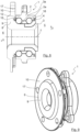
- the Figures 5 and 6 show another embodiment of the wheel bearing 1 and a matching brake disc 11. It can be seen that the contact surface 10 for the brake disc 11 in the radial direction z further outside than in the embodiment of FIG Figures 2 to 4 located. As a result, the inner diameter of the brake disc 11 can be increased even further, resulting in smaller recesses 14 for the wheel bolts 13 to pass through.
- the recesses 14 in the brake disc 11 are open in the direction of the inner diameter of the brake disc 11 otherwise necessary drilling of the same can be dispensed with. If the brake disk 11 is not centered via the recesses 14, they can remain in the raw state. The brake disc 11 can also be centered via the lower or the upper end of the second contact surface 10 for the brake disc 11 .
- a1 > a2 The end of the flange section 8 on the outside of the vehicle is closer to the outside of the vehicle 6 than the contact surface 10 for the brake disc 11.
- b1 > b2 The area referred to as the screw connection area, in which the wheel bolts 13 are located, is shifted radially in relation to the wheel hub outside of parts of the outer ring 2, the wheel bearing seal 15 or the rolling element set 4 in the direction of the inside 5 of the vehicle.
- c1 > c2 The inner diameter of the brake disc 11 is larger than the diameter of the running surface 2a of the outer ring 2, measured in contact angle.
- FIG. 8 to 10 several views of a further embodiment of the wheel bearing 1 are shown.
- wheel bearing seals 15 and 16 arranged between the outer ring 2 and the inner ring 3 can be seen.
- the projection 12 is arranged radially outside of the wheel-side wheel bearing seal 15.
- the wheel bolts 13 are replaced by corresponding bores 17 into which wheel bolts (not shown) are screwed in order to fasten the wheel. Also in this embodiment variant apply with reference to 7 described proportions.
Landscapes
- Engineering & Computer Science (AREA)
- General Engineering & Computer Science (AREA)
- Mechanical Engineering (AREA)
- Rolling Contact Bearings (AREA)
- Braking Arrangements (AREA)
Description
Die Erfindung betrifft eine Radlageranordnung für ein Kraftfahrzeug nach der im Oberbegriff von Anspruch 1 näher definierten Art.The invention relates to a wheel bearing arrangement for a motor vehicle according to the type defined in more detail in the preamble of
Eine gattungsgemäße Radlageranordnung ist aus der
Ein weiteres derartiges Radlager ist aus der
Ein weiteres derartiges Radlager beschreibt die
Die
Das Problem der bekannten Radlager ist deren verhältnismäßig großer Platzbedarf und das hohe Gewicht derselben.The problem with the known wheel bearings is their relatively large space requirement and the high weight of the same.
Es ist daher Aufgabe der vorliegenden Erfindung, eine Radlageranordnung für ein Kraftfahrzeug mit einer kompakten und gewichtsoptimierten Bauweise zu schaffen.It is therefore the object of the present invention to create a wheel bearing arrangement for a motor vehicle with a compact and weight-optimized design.
Erfindungsgemäß wird diese Aufgabe durch die in Anspruch 1 genannten Merkmale gelöst.According to the invention, this object is achieved by the features mentioned in
Durch die erfindungsgemäß gestufte bzw. gekröpfte Ausführung des Flanschabschnitts ergibt sich eine sehr kompakte Bauweise des Radlagers der erfindungsgemäßen Radlageranordnung, da die Anlagefläche für die Bremsscheibe mit einem entsprechend groß ausgeführten Innendurchmesser in Richtung der Fahrzeuginnenseite verschoben wird, so dass sich der in axialer Richtung notwendige Bauraum für das Radlager und für die an demselben befestigte Bremsscheibe verkleinert, da die Dicke des Bremsscheibentopfes ganz oder zumindest teilweise aus der axialen Maßkette für den axialen Bauraum verschwindet. Gleichzeitig weist der rückwärtige Flanschabschnitt auf der der Anlagefläche für die Bremsscheibe gegenüberliegenden Seite einen zumindest teilweise umlaufenden Vorsprung auf, der die Festigkeit des Flanschabschnitts erhöht bzw. gegenüber einer konventionellen, nicht gekröpften Lösung beibehält. Da sich dieser umlaufende Vorsprung in Richtung der Fahrzeuginnenseite befindet, trägt er vorteilhafterweise nicht zur Vergrößerung des axialen Bauraums des erfindungsgemäßen Radlagers bei. Die gestufte Ausführung des Flanschabschnitts ist dabei nicht nur lokal im Bereich der Radschrauben bzw. Radbolzen, sondern um den gesamten Umfang des Radlagers vorgesehen.The stepped or cranked design of the flange section according to the invention results in a very compact design of the wheel bearing of the wheel bearing arrangement according to the invention, since the contact surface for the brake disc with a correspondingly large inner diameter is displaced in the direction of the inside of the vehicle, so that the installation space required in the axial direction is increased for the wheel bearing and for the brake disc fastened to it is reduced, since the thickness of the brake disc chamber disappears completely or at least partially from the axial chain of dimensions for the axial installation space. At the same time, the rear flange section has an at least partially circumferential projection on the side opposite the contact surface for the brake disc, which increases the strength of the flange section or maintains it compared to a conventional, non-offset solution. Since this circumferential projection is located in the direction of the inside of the vehicle, it advantageously does not contribute to increasing the axial installation space of the wheel bearing according to the invention. The stepped design of the flange section is provided not only locally in the area of the wheel bolts or wheel bolts, but around the entire circumference of the wheel bearing.
Um eine im Bereich der Fahrzeugaußenseite annähernd ebene Fläche zu erzeugen, ist erfindungsgemäß des Weiteren vorgesehen, dass der Versatz der Anlagefläche zum Anbringen der Bremsscheibe gegenüber dem am weitesten von der axialen Mitte des Außenrings beabstandeten Abschnitt des Flanschabschnitts in axialer Richtung der Dicke der Bremsscheibe entspricht. Die Bauraumersparnis durch die erfindungsgemä-ße Stufung des Flanschabschnitts entspräche in dieser Variante damit exakt der Dicke bzw. der Stärke der Bremsscheibe.In order to produce an approximately flat surface in the area of the vehicle exterior, the invention also provides that the offset of the contact surface for attaching the brake disc compared to the section of the flange section that is furthest from the axial center of the outer ring corresponds in the axial direction to the thickness of the brake disc. In this variant, the saving in installation space due to the stepping of the flange section according to the invention would correspond exactly to the thickness or strength of the brake disc.
In einer sehr vorteilhaften Weiterbildung der Erfindung kann vorgesehen sein, dass die Anlagefläche zum Anbringen der Bremsscheibe gegenüber dem am weitesten von der axialen Mitte des Außenrings beabstandeten Abschnitt des Flanschabschnitts in radialer Richtung außen angeordnet ist. Dadurch ergibt sich ein im Vergleich zu bekannten Lösungen vergrößerter Innendurchmesser der Bremsscheibe, so dass im mittleren Bereich des Radlagers, also in dem Bereich um dessen Längsachse, zusätzlicher Platz entsteht. Durch die Vergrößerung des Innendurchmessers der Bremsscheibe kann außerdem das Gewicht derselben verringert werden. Des Weiteren lässt sich über den größeren Durchmesser der Bremsscheibe eine höhere Reibung übertragen.In a very advantageous development of the invention, it can be provided that the contact surface for attaching the brake disc is arranged on the outside in the radial direction in relation to the section of the flange section that is spaced furthest from the axial center of the outer ring. This results in an increased inner diameter of the brake disc compared to known solutions, so that additional space is created in the middle area of the wheel bearing, ie in the area around its longitudinal axis. In addition, by increasing the inner diameter of the brake disk, the weight of the same can be reduced. Furthermore, higher friction can be transmitted via the larger diameter of the brake disc.
Die erfindungsgemäße, sehr kompakte Bauweise des Radlagers kann noch dadurch verbessert werden, dass der sich auf der der Anlagefläche zum Anbringen der Bremsscheibe gegenüberliegenden Seite befindende, zumindest teilweise umlaufende Vorsprung in radialer Richtung außerhalb von Teilen des Außenrings, einer Radlagerdichtung oder eines Wälzkörpersatzes angeordnet ist.The very compact design of the wheel bearing according to the invention can be further improved in that the at least partially circumferential projection located on the side opposite the contact surface for attaching the brake disc is arranged in the radial direction outside of parts of the outer ring, a wheel bearing seal or a rolling element set.
Dasselbe gilt, wenn der Innendurchmesser der Bremsscheibe größer ist als der Durchmesser einer Lauffläche des Außenrings, gemessen im Kontaktwinkel, beispielsweise bei einem verkürzten Außenring.The same applies if the inner diameter of the brake disc is larger than the diameter of a running surface of the outer ring, measured in the contact angle, for example with a shortened outer ring.
In einer sehr vorteilhaften Weiterbildung der Erfindung wird der Innendurchmesser des Bremsscheibentopfes erhöht, um das Radlager in axialer Richtung unter der Bremsscheibe nach Fahrzeugaußen auszudehnen. Dadurch kann unter Beibehaltung des axialen Bauraums einer konventionellen Lösung ein größerer Reihenabstand oder mehr Dichtraum realisiert werden, was sich vorteilhaft auf die Lebensdauer und Dichtigkeit auswirkt. Außerdem werden doppelte Flansche vermieden und damit eine Reduzierung des Gewichts erreicht. Die Ausdehnung kann auch in den Bereich der Felge hineinragen.In a very advantageous further development of the invention, the inner diameter of the brake disc chamber is increased in order to expand the wheel bearing in the axial direction under the brake disc to the outside of the vehicle. As a result, while retaining the axial installation space of a conventional solution, a larger row spacing or more sealing space can be implemented, which has an advantageous effect on the service life and tightness. In addition, double flanges are avoided and thus a reduction in weight reached. The expansion can also protrude into the area of the rim.
Des Weiteren kann vorgesehen sein, dass die Bremsscheibe einen derartigen Innendurchmesser aufweist, dass an dem Radlager angebrachte Radbolzen zumindest teilweise radial weiter außen liegen als der Innendurchmesser der Bremsscheibe, d.h. die Durchgangsbohrungen für die Radbolzen in der Bremsscheibe müssen nach radial innen nicht geschlossen sein. Ein Vorteil dieser Ausführung ist, dass auf ein aufwändiges Herstellen des Bohrbildes der Bremsscheibe (Innenzentrierung und Bohrungen für Radbolzen) verzichtet werden kann, da die Positionier- und Zentrierkulisse bereits in der Gussform vorgehalten werden kann.Furthermore, it can be provided that the brake disc has an inner diameter such that wheel bolts attached to the wheel bearing are at least partially radially further outward than the inner diameter of the brake disc, i.e. the through bores for the wheel bolts in the brake disc do not have to be closed radially inward. One advantage of this design is that there is no need to laboriously produce the hole pattern for the brake disc (internal centering and holes for wheel bolts), since the positioning and centering link can already be provided in the mold.
Nachfolgend sind Ausführungsbeispiele der Erfindung anhand der Zeichnung prinzipmäßig dargestellt.In the following, exemplary embodiments of the invention are shown in principle with reference to the drawing.
Es zeigt:
- Fig. 1
- eine Schnittansicht des erfindungsgemäßen Radlagers im Zusammenbau mit Radträger und Bremsscheibe;
- Fig. 2
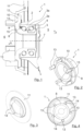
- eine perspektivische Ansicht einer ersten Ausführungsform des erfindungsgemäßen Radlagers;
- Fig. 3
- eine perspektivische Ansicht einer zu dem Radlager aus
Fig. 2 passenden Bremsscheibe; - Fig. 4
- eine Draufsicht auf eine mit dem Radlager aus
Fig. 2 montierte Bremsscheibe ausFig. 3 ; - Fig. 5
- eine perspektivische Ansicht einer zweiten Ausführungsform des erfindungsgemäßen Radlagers;
- Fig. 6
- eine perspektivische Ansicht einer zu dem Radlager aus
Fig. 5 passenden Bremsscheibe; - Fig. 7
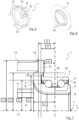
- eine Schnittansicht des erfindungsgemäßen Radlagers mit darin eingezeichneten Maßen;
- Fig. 8
- eine Schnittansicht einer weiteren Ausführungsform des erfindungsgemäßen Radlagers;
- Fig. 9
- eine perspektivische Ansicht des Radlagers aus
Fig. 8 ; - Fig. 10
- eine weitere perspektivische Ansicht des Radlagers aus
Fig. 8 ; und - Fig. 11
- eine Seitenansicht des Radlagers aus
Fig. 8 .
- 1
- a sectional view of the wheel bearing according to the invention in assembly with wheel carrier and brake disc;
- 2
- a perspective view of a first embodiment of the wheel bearing according to the invention;
- 3
- a perspective view of the wheel bearing
2 matching brake disc; - 4
- a top view of one with the wheel bearing off
2 installedbrake disc 3 ; - figure 5
- a perspective view of a second embodiment of the wheel bearing according to the invention;
- 6
- a perspective view of the wheel bearing
figure 5 matching brake disc; - 7
- a sectional view of the wheel bearing according to the invention with dimensions drawn therein;
- 8
- a sectional view of a further embodiment of the wheel bearing according to the invention;
- 9
- a perspective view of the
wheel bearing 8 ; - 10
- Another perspective view of the
wheel bearing 8 ; and - 11
- a side view of the
wheel bearing 8 .
Das Radlager 1 weist eine in der mit "x" bezeichneten axialen Richtung des Außenrings 2 und des Innenrings 3 von einer Fahrzeuginnenseite 5 zu einer Fahrzeugaußenseite 6 verlaufende Längsachse 7 auf. An der Fahrzeugaußenseite 6 des Radlagers 1 kann in an sich bekannter Weise ein nicht dargestelltes Rad befestigt werden. Hierzu weist der Innenring 3 an seinem der Fahrzeugaußenseite 6 zugerichteten Ende einen Flanschabschnitt 8 auf, der einen ersten Abschnitt 9, der als am weitesten von einer axialen Mitte des Außenrings 2 beabstandeter Abschnitt 9 bezeichnet wird, und einen zweiten Abschnitt aufweist, der eine Anlagefläche 10 zum Anbringen einer Bremsscheibe 11 bildet, an der wiederum das nicht dargestellte Rad über Radbolzen 13 fixiert wird.The
Wie in
Auf der der Anlagefläche 10 für die Bremsscheibe 11 gegenüberliegenden Seite weist der Flanschabschnitt 8 einen zumindest in festigkeitsrelevanten Bereichen, insbesondere vom Verbindungsbereich der Radbolzen 13 zu dem zwischen dem Außenring 2 und dem Innenring 3 befindlichen Kugelsatz, umlaufenden Vorsprung 12 auf. Dadurch ergeben sich größere Wandstärken als es bei einem reinen Absatz der Fall wäre. Da der Flansch i.d.R. als Schmiedeteil mit anschließender spanender Bearbeitung hergestellt wird, ergibt sich dadurch außerdem ein für die Festigkeit zuträglicher metallurgischer Faserverlauf. Dennoch kann diese Kontur auch mit anderen Fertigungsverfahren hergestellt werden, beispielweise mittels Gießen und/oder spanend.On the side opposite the
Der umlaufende Vorsprung 12 befindet sich, wie ebenfalls aus
Der Vorsprung 12 kann je nach Geometrie des Außenrings 2 jedoch auch nur radial außerhalb der Lauffläche 2a des Außenrings 2 oder eines Bereich der radseitigen Radlagerdichtung angeordnet sein.Depending on the geometry of the
Des Weiteren ist in
In den
Die
Aufgrund der in Richtung des Innendurchmessers der Bremsscheibe 11 geöffneten Ausführung der Ausnehmungen 14 in der Bremsscheibe 11 kann auf ein ansonsten notwendiges Bohren derselben verzichtet werden. Wenn über die Ausnehmungen 14 keine Zentrierung der Bremsscheibe 11 erfolgt, können diese im rohen Zustand verbleiben. Eine Zentrierung der Bremsscheibe 11 ist auch über das untere oder das obere Ende der zweiten Anlagefläche 10 für die Bremsscheibe 11 möglich.Because the
In
- a1 =
- Abstand des fahrzeugaußenseitigen Endes des Flanschabschnitts 8 von der Mitte des
Radlagers 1. - a2 =
Abstand der Anlagefläche 10 für dieBremsscheibe 11 von der Mitte desRadlagers 1.- b1 =
- Abstand des Flanschabschnitts 8 im Bereich radial innerhalb des Durchmessers c4 von der Mitte des
Radlagers 1. - b2 =
- Abstand des Flanschabschnitts 8 im Bereich radial außerhalb des Durchmessers c4 von der Mitte des
Radlagers 1. - c1 =
- Abstand des unteren Absatzes der Anlagefläche 10 für die
Bremsscheibe 11von der Längsachse 7 desRadlagers 1. - c2 =
Abstand der Lauffläche 2a desAußenrings 2von der Längsachse 7 desRadlagers 1.- c3 =
- Abstand der äußeren Kante des
Flanschabschnitts 8von der Längsachse 7 desRadlagers 1. - c4 =
- Abstand der Aussparung des Innenrings 3 für Teile des
Außenrings 2,der Radlagerdichtung 15 oder des Wälzkörpersatzes 4von der Längsachse 7 desRadlagers 1.
- a1 =
- Distance of the end of the
flange section 8 on the outside of the vehicle from the center of thewheel bearing 1. - a2 =
- Distance of the
contact surface 10 for thebrake disc 11 from the center of thewheel bearing 1. - b1 =
- Distance of the
flange section 8 in the area radially inside the diameter c4 from the center of thewheel bearing 1. - b2 =
- Distance of the
flange section 8 in the area radially outside the diameter c4 from the center of thewheel bearing 1. - c1 =
- Distance of the lower shoulder of the
contact surface 10 for thebrake disc 11 from thelongitudinal axis 7 of thewheel bearing 1. - c2 =
- Distance of the running
surface 2a of theouter ring 2 from thelongitudinal axis 7 of thewheel bearing 1. - c3 =
- Distance of the outer edge of the
flange section 8 from thelongitudinal axis 7 of thewheel bearing 1. - c4 =
- Distance of the recess of the
inner ring 3 for parts of theouter ring 2, thewheel bearing seal 15 or the rolling element set 4 from thelongitudinal axis 7 of thewheel bearing 1.
Hierbei gelten im vorliegenden Fall folgende Verhältnisse:
In den
Claims (6)
- Radial bearing arrangement (1) for a motor vehicle with an outer ring (2), with an inner ring (3) arranged at least partially inside the outer ring (2), with a longitudinal axis (7) extending in axial direction (x) of the outer ring (2) and the inner ring (3) from a vehicle inner side (5) to a vehicle outer side (6) and with a brake disc (11), wherein the inner ring (3) is provided at its end facing the vehicle outer side (6) with a flange section (8) having a first section (9) arranged spaced at the furthest point from an axial centre of the outer ring (2), and a second section, which forms a contact surface (10) for attaching the brake disk (11), wherein the flange section (8) is configured to be stepped such that the contact surface (10) for attaching the brake disk (11) is arranged offset relative to the section (9) of the flange section (8) spaced at the furthest point from the axial centre of the outer ring (2) in axial direction (x) towards the vehicle inner side (5), wherein on the side opposite the contact surface (10) for attaching the brake disk (11) an at least partially peripheral projection (12) is arranged, and the projection (12) forms an undercut into which at least one wheel bearing seal (15) projects, characterised in that the offset of the contact surface (10) for attaching the brake disc (11) with respect to the section (9) of the flange section (8) furthest from the axial centre of the outer ring (2) corresponds in axial direction (x) to the thickness of the brake disc (11).
- Wheel bearing arrangement according to claim 1,
characterised in that
the contact surface (10) for attaching the brake disk (11) is arranged outside relative to the section (9) of the flange section (8) in radial direction (z) at the furthest point from the axial centre of the outer ring (2). - Wheel bearing arrangement according to claim 1 or 2,
characterised in that
the at least partially peripheral projection (12) located on the side opposite the contact surface (10) for attaching the brake disc (11) is arranged in radial direction (z) outside parts of the outer ring (2), a wheel bearing seal (15) or a roller element set (4). - Wheel bearing arrangement according to claim 1, 2 or 3,
characterised in that
the inner diameter of the brake disk (11) is larger than the diameter of a bearing surface (2a) of the outer ring (2) measured in a contact angle. - Wheel bearing arrangement according to any of claims 1 to 4,
characterised in that
the brake disk (11) has such an inner diameter that wheel bolts (13) attached to the wheel bearing (1) lie at least partly radially further out than the inner diameter of the brake disk (11). - Wheel bearing arrangement according to claim 5,
characterised in that
the brake disk (11) is provided with recesses (14) for feeding through the wheel bolts (13).
Applications Claiming Priority (1)
| Application Number | Priority Date | Filing Date | Title |
|---|---|---|---|
| DE102017200338.3A DE102017200338A1 (en) | 2017-01-11 | 2017-01-11 | Wheel bearing for a motor vehicle |
Publications (2)
| Publication Number | Publication Date |
|---|---|
| EP3351403A1 EP3351403A1 (en) | 2018-07-25 |
| EP3351403B1 true EP3351403B1 (en) | 2023-07-05 |
Family
ID=58490472
Family Applications (1)
| Application Number | Title | Priority Date | Filing Date |
|---|---|---|---|
| EP17206766.2A Active EP3351403B1 (en) | 2017-01-11 | 2017-12-12 | Wheel bearing for a motor vehicle |
Country Status (4)
| Country | Link |
|---|---|
| US (1) | US10267355B2 (en) |
| EP (1) | EP3351403B1 (en) |
| CN (1) | CN108297615B (en) |
| DE (1) | DE102017200338A1 (en) |
Families Citing this family (3)
| Publication number | Priority date | Publication date | Assignee | Title |
|---|---|---|---|---|
| DE102017204203A1 (en) | 2017-03-14 | 2017-07-20 | Audi Ag | Wheel bearing arrangement for a motor vehicle |
| JP7365769B2 (en) * | 2019-01-25 | 2023-10-20 | Ntn株式会社 | Bearing device for wheels |
| DE102019205782B4 (en) | 2019-04-23 | 2022-04-28 | Audi Ag | Wheel bearing arrangement for a motor vehicle |
Family Cites Families (20)
| Publication number | Priority date | Publication date | Assignee | Title |
|---|---|---|---|---|
| DE3024397A1 (en) * | 1980-06-28 | 1982-01-21 | Skf Kugellagerfabriken Gmbh | ROLLER BEARING |
| DE3140373A1 (en) | 1981-10-10 | 1983-04-28 | Skf Kugellagerfabriken Gmbh, 8720 Schweinfurt | WHEEL BEARING UNIT FOR DRIVED WHEELS OF MOTOR VEHICLES |
| JP2000227132A (en) * | 1998-12-02 | 2000-08-15 | Ntn Corp | Wheel bearing device with brake rotor |
| US6575637B1 (en) | 1999-09-10 | 2003-06-10 | Ntn Corporation | Brake rotor and wheel bearing assembly |
| EP1470935B8 (en) * | 2002-01-30 | 2008-09-03 | Nsk Ltd., | Bearing unit for vehicle wheel |
| ITTO20040316A1 (en) | 2004-05-14 | 2004-08-14 | Skf Ab | DEVICE FOR CONNECTION OF A ROLLING BEARING TO AN EXTERNAL BODY |
| JP2006248373A (en) * | 2005-03-10 | 2006-09-21 | Ntn Corp | Bearing device for wheel |
| US7913374B2 (en) | 2005-08-09 | 2011-03-29 | Ntn Corporation | Processing method for brake rotor-equipped wheel bearing devices |
| WO2007078616A2 (en) | 2005-12-22 | 2007-07-12 | Timken Us Corporation | Tapered bearing and method for manufacturing |
| JP2009286238A (en) | 2008-05-29 | 2009-12-10 | Ntn Corp | Wheel bearing device |
| DE102008034627A1 (en) * | 2008-07-25 | 2010-01-28 | Schaeffler Kg | Rolling bearings with flange |
| DE102011003704B4 (en) * | 2011-02-07 | 2018-09-13 | Schaeffler Technologies AG & Co. KG | Labyrinth seal of a radial bearing with radial flange |
| CN202345276U (en) * | 2011-11-15 | 2012-07-25 | 杭州萧山鼎立机械有限公司 | Hub unit of steel ball retainer |
| WO2013100285A1 (en) * | 2011-12-26 | 2013-07-04 | 주식회사 일진글로벌 | Coupled wheel bearing structure |
| ITTO20120309A1 (en) * | 2012-04-06 | 2013-10-07 | Skf Ab | BEARING GROUP HUB SHIELDED FOR THE WHEEL OF A MOTOR VEHICLE |
| ITTO20120604A1 (en) * | 2012-07-09 | 2014-01-10 | Skf Ab | BEARING-HUB ASSEMBLY UNIT WITH SEALING DEVICE |
| JP2015010681A (en) | 2013-07-01 | 2015-01-19 | 株式会社ジェイテクト | Bearing unit |
| JP6309326B2 (en) * | 2014-03-31 | 2018-04-11 | 本田技研工業株式会社 | Wheel support mechanism |
| JP2016003709A (en) | 2014-06-17 | 2016-01-12 | Ntn株式会社 | Wheel bearing device |
| CN204398747U (en) * | 2015-01-30 | 2015-06-17 | 浙江长兴加泰尔汽车部件制造有限公司 | There is the automobile hub unit of ABS function |
-
2017
- 2017-01-11 DE DE102017200338.3A patent/DE102017200338A1/en not_active Withdrawn
- 2017-12-12 EP EP17206766.2A patent/EP3351403B1/en active Active
- 2017-12-27 US US15/855,040 patent/US10267355B2/en active Active
-
2018
- 2018-01-10 CN CN201810021703.0A patent/CN108297615B/en active Active
Also Published As
| Publication number | Publication date |
|---|---|
| CN108297615B (en) | 2021-03-16 |
| US10267355B2 (en) | 2019-04-23 |
| EP3351403A1 (en) | 2018-07-25 |
| CN108297615A (en) | 2018-07-20 |
| DE102017200338A1 (en) | 2017-04-27 |
| US20180195552A1 (en) | 2018-07-12 |
Similar Documents
| Publication | Publication Date | Title |
|---|---|---|
| DE69612916T2 (en) | HYDRAULICALLY ACTUATED RELEASE BEARING FOR VEHICLE CLUTCH WITH DIAPHRAGM SPRING | |
| WO2012019799A1 (en) | Wheel bearing unit | |
| EP3351403B1 (en) | Wheel bearing for a motor vehicle | |
| EP3212433B1 (en) | Vehicle wheel having a connection between a wheel rim and a wheel disc and method for the production thereof | |
| WO2012107118A1 (en) | Labyrinth seal of a radial rolling contact bearing having a radial flange | |
| WO2008086764A1 (en) | Roller bearing cage for guiding rolling bodies in a rolling body bearing, and rolling body bearing | |
| WO2008086765A2 (en) | Pocket cage for a rolling body bearing and rolling body bearing comprising a pocket cage | |
| DE112005002498T5 (en) | Wheel support bearing assembly | |
| WO2009049755A1 (en) | Rolling bearing which can be loaded radially and axially | |
| DE102008044136A1 (en) | Wheel carrier of a motor vehicle | |
| EP2831453A1 (en) | Disk brake, in particular for a utility vehicle | |
| WO2015082454A2 (en) | Can, and a method for producing same | |
| DE2137595A1 (en) | Axis spindle and process for their manufacture | |
| DE102005034717A1 (en) | Outer race for double-row sealed anti-friction bearing is divided into two joined outer race sections with seal e.g. O-ring, plastic ring, at their juncture | |
| EP1731778B1 (en) | Bearing arrangement | |
| EP1704339A1 (en) | Outer ring of a wheel bearing, and axial securing element for said outer ring | |
| WO2015082428A1 (en) | Arrangement of a brake disk on a wheel hub | |
| EP2265834B1 (en) | Cage for a rolling element bearing | |
| DE112005000496T5 (en) | Hub unit for a wheel | |
| EP2661375B1 (en) | Wheel bearing arrangement for trucks | |
| WO2017080794A1 (en) | Wheel bearing device, and method for mounting a wheel bearing device | |
| WO2005058614A1 (en) | Wheel bearing module in a wheel carrier | |
| DE102004034217A1 (en) | Split stabilizer with optimized spring rate | |
| EP3638918B1 (en) | Friction ring element, friction ring set for arranging on the wheel web of a track wheel, and track wheel brake | |
| DE19836239C2 (en) | vehicle |
Legal Events
| Date | Code | Title | Description |
|---|---|---|---|
| PUAI | Public reference made under article 153(3) epc to a published international application that has entered the european phase |
Free format text: ORIGINAL CODE: 0009012 |
|
| STAA | Information on the status of an ep patent application or granted ep patent |
Free format text: STATUS: THE APPLICATION HAS BEEN PUBLISHED |
|
| AK | Designated contracting states |
Kind code of ref document: A1 Designated state(s): AL AT BE BG CH CY CZ DE DK EE ES FI FR GB GR HR HU IE IS IT LI LT LU LV MC MK MT NL NO PL PT RO RS SE SI SK SM TR |
|
| AX | Request for extension of the european patent |
Extension state: BA ME |
|
| STAA | Information on the status of an ep patent application or granted ep patent |
Free format text: STATUS: REQUEST FOR EXAMINATION WAS MADE |
|
| 17P | Request for examination filed |
Effective date: 20181011 |
|
| RBV | Designated contracting states (corrected) |
Designated state(s): AL AT BE BG CH CY CZ DE DK EE ES FI FR GB GR HR HU IE IS IT LI LT LU LV MC MK MT NL NO PL PT RO RS SE SI SK SM TR |
|
| STAA | Information on the status of an ep patent application or granted ep patent |
Free format text: STATUS: REQUEST FOR EXAMINATION WAS MADE |
|
| STAA | Information on the status of an ep patent application or granted ep patent |
Free format text: STATUS: EXAMINATION IS IN PROGRESS |
|
| STAA | Information on the status of an ep patent application or granted ep patent |
Free format text: STATUS: EXAMINATION IS IN PROGRESS |
|
| 17Q | First examination report despatched |
Effective date: 20211020 |
|
| RIC1 | Information provided on ipc code assigned before grant |
Ipc: B60B 27/02 20060101ALN20230216BHEP Ipc: B60B 27/00 20060101AFI20230216BHEP |
|
| RIC1 | Information provided on ipc code assigned before grant |
Ipc: B60B 27/02 20060101ALN20230315BHEP Ipc: B60B 27/00 20060101AFI20230315BHEP |
|
| GRAP | Despatch of communication of intention to grant a patent |
Free format text: ORIGINAL CODE: EPIDOSNIGR1 |
|
| STAA | Information on the status of an ep patent application or granted ep patent |
Free format text: STATUS: GRANT OF PATENT IS INTENDED |
|
| RIC1 | Information provided on ipc code assigned before grant |
Ipc: B60B 27/02 20060101ALN20230328BHEP Ipc: B60B 27/00 20060101AFI20230328BHEP |
|
| GRAS | Grant fee paid |
Free format text: ORIGINAL CODE: EPIDOSNIGR3 |
|
| INTG | Intention to grant announced |
Effective date: 20230503 |
|
| GRAA | (expected) grant |
Free format text: ORIGINAL CODE: 0009210 |
|
| STAA | Information on the status of an ep patent application or granted ep patent |
Free format text: STATUS: THE PATENT HAS BEEN GRANTED |
|
| AK | Designated contracting states |
Kind code of ref document: B1 Designated state(s): AL AT BE BG CH CY CZ DE DK EE ES FI FR GB GR HR HU IE IS IT LI LT LU LV MC MK MT NL NO PL PT RO RS SE SI SK SM TR |
|
| P01 | Opt-out of the competence of the unified patent court (upc) registered |
Effective date: 20230529 |
|
| REG | Reference to a national code |
Ref country code: CH Ref legal event code: EP |
|
| REG | Reference to a national code |
Ref country code: AT Ref legal event code: REF Ref document number: 1584522 Country of ref document: AT Kind code of ref document: T Effective date: 20230715 |
|
| REG | Reference to a national code |
Ref country code: DE Ref legal event code: R096 Ref document number: 502017015000 Country of ref document: DE |
|
| REG | Reference to a national code |
Ref country code: IE Ref legal event code: FG4D Free format text: LANGUAGE OF EP DOCUMENT: GERMAN |
|
| REG | Reference to a national code |
Ref country code: LT Ref legal event code: MG9D |
|
| REG | Reference to a national code |
Ref country code: NL Ref legal event code: MP Effective date: 20230705 |
|
| PG25 | Lapsed in a contracting state [announced via postgrant information from national office to epo] |
Ref country code: NL Free format text: LAPSE BECAUSE OF FAILURE TO SUBMIT A TRANSLATION OF THE DESCRIPTION OR TO PAY THE FEE WITHIN THE PRESCRIBED TIME-LIMIT Effective date: 20230705 |
|
| PG25 | Lapsed in a contracting state [announced via postgrant information from national office to epo] |
Ref country code: GR Free format text: LAPSE BECAUSE OF FAILURE TO SUBMIT A TRANSLATION OF THE DESCRIPTION OR TO PAY THE FEE WITHIN THE PRESCRIBED TIME-LIMIT Effective date: 20231006 |
|
| PGFP | Annual fee paid to national office [announced via postgrant information from national office to epo] |
Ref country code: GB Payment date: 20231218 Year of fee payment: 7 |
|
| PG25 | Lapsed in a contracting state [announced via postgrant information from national office to epo] |
Ref country code: ES Free format text: LAPSE BECAUSE OF FAILURE TO SUBMIT A TRANSLATION OF THE DESCRIPTION OR TO PAY THE FEE WITHIN THE PRESCRIBED TIME-LIMIT Effective date: 20230705 |
|
| PG25 | Lapsed in a contracting state [announced via postgrant information from national office to epo] |
Ref country code: IS Free format text: LAPSE BECAUSE OF FAILURE TO SUBMIT A TRANSLATION OF THE DESCRIPTION OR TO PAY THE FEE WITHIN THE PRESCRIBED TIME-LIMIT Effective date: 20231105 |
|
| PG25 | Lapsed in a contracting state [announced via postgrant information from national office to epo] |
Ref country code: SE Free format text: LAPSE BECAUSE OF FAILURE TO SUBMIT A TRANSLATION OF THE DESCRIPTION OR TO PAY THE FEE WITHIN THE PRESCRIBED TIME-LIMIT Effective date: 20230705 Ref country code: RS Free format text: LAPSE BECAUSE OF FAILURE TO SUBMIT A TRANSLATION OF THE DESCRIPTION OR TO PAY THE FEE WITHIN THE PRESCRIBED TIME-LIMIT Effective date: 20230705 Ref country code: PT Free format text: LAPSE BECAUSE OF FAILURE TO SUBMIT A TRANSLATION OF THE DESCRIPTION OR TO PAY THE FEE WITHIN THE PRESCRIBED TIME-LIMIT Effective date: 20231106 Ref country code: NO Free format text: LAPSE BECAUSE OF FAILURE TO SUBMIT A TRANSLATION OF THE DESCRIPTION OR TO PAY THE FEE WITHIN THE PRESCRIBED TIME-LIMIT Effective date: 20231005 Ref country code: LV Free format text: LAPSE BECAUSE OF FAILURE TO SUBMIT A TRANSLATION OF THE DESCRIPTION OR TO PAY THE FEE WITHIN THE PRESCRIBED TIME-LIMIT Effective date: 20230705 Ref country code: LT Free format text: LAPSE BECAUSE OF FAILURE TO SUBMIT A TRANSLATION OF THE DESCRIPTION OR TO PAY THE FEE WITHIN THE PRESCRIBED TIME-LIMIT Effective date: 20230705 Ref country code: IS Free format text: LAPSE BECAUSE OF FAILURE TO SUBMIT A TRANSLATION OF THE DESCRIPTION OR TO PAY THE FEE WITHIN THE PRESCRIBED TIME-LIMIT Effective date: 20231105 Ref country code: HR Free format text: LAPSE BECAUSE OF FAILURE TO SUBMIT A TRANSLATION OF THE DESCRIPTION OR TO PAY THE FEE WITHIN THE PRESCRIBED TIME-LIMIT Effective date: 20230705 Ref country code: GR Free format text: LAPSE BECAUSE OF FAILURE TO SUBMIT A TRANSLATION OF THE DESCRIPTION OR TO PAY THE FEE WITHIN THE PRESCRIBED TIME-LIMIT Effective date: 20231006 Ref country code: FI Free format text: LAPSE BECAUSE OF FAILURE TO SUBMIT A TRANSLATION OF THE DESCRIPTION OR TO PAY THE FEE WITHIN THE PRESCRIBED TIME-LIMIT Effective date: 20230705 Ref country code: ES Free format text: LAPSE BECAUSE OF FAILURE TO SUBMIT A TRANSLATION OF THE DESCRIPTION OR TO PAY THE FEE WITHIN THE PRESCRIBED TIME-LIMIT Effective date: 20230705 |
|
| PGFP | Annual fee paid to national office [announced via postgrant information from national office to epo] |
Ref country code: FR Payment date: 20231220 Year of fee payment: 7 Ref country code: DE Payment date: 20231231 Year of fee payment: 7 |
|
| PG25 | Lapsed in a contracting state [announced via postgrant information from national office to epo] |
Ref country code: PL Free format text: LAPSE BECAUSE OF FAILURE TO SUBMIT A TRANSLATION OF THE DESCRIPTION OR TO PAY THE FEE WITHIN THE PRESCRIBED TIME-LIMIT Effective date: 20230705 |
|
| REG | Reference to a national code |
Ref country code: DE Ref legal event code: R097 Ref document number: 502017015000 Country of ref document: DE |
|
| PG25 | Lapsed in a contracting state [announced via postgrant information from national office to epo] |
Ref country code: SM Free format text: LAPSE BECAUSE OF FAILURE TO SUBMIT A TRANSLATION OF THE DESCRIPTION OR TO PAY THE FEE WITHIN THE PRESCRIBED TIME-LIMIT Effective date: 20230705 Ref country code: RO Free format text: LAPSE BECAUSE OF FAILURE TO SUBMIT A TRANSLATION OF THE DESCRIPTION OR TO PAY THE FEE WITHIN THE PRESCRIBED TIME-LIMIT Effective date: 20230705 Ref country code: EE Free format text: LAPSE BECAUSE OF FAILURE TO SUBMIT A TRANSLATION OF THE DESCRIPTION OR TO PAY THE FEE WITHIN THE PRESCRIBED TIME-LIMIT Effective date: 20230705 Ref country code: DK Free format text: LAPSE BECAUSE OF FAILURE TO SUBMIT A TRANSLATION OF THE DESCRIPTION OR TO PAY THE FEE WITHIN THE PRESCRIBED TIME-LIMIT Effective date: 20230705 Ref country code: CZ Free format text: LAPSE BECAUSE OF FAILURE TO SUBMIT A TRANSLATION OF THE DESCRIPTION OR TO PAY THE FEE WITHIN THE PRESCRIBED TIME-LIMIT Effective date: 20230705 Ref country code: SK Free format text: LAPSE BECAUSE OF FAILURE TO SUBMIT A TRANSLATION OF THE DESCRIPTION OR TO PAY THE FEE WITHIN THE PRESCRIBED TIME-LIMIT Effective date: 20230705 |
|
| PLBE | No opposition filed within time limit |
Free format text: ORIGINAL CODE: 0009261 |
|
| STAA | Information on the status of an ep patent application or granted ep patent |
Free format text: STATUS: NO OPPOSITION FILED WITHIN TIME LIMIT |
|
| PG25 | Lapsed in a contracting state [announced via postgrant information from national office to epo] |
Ref country code: IT Free format text: LAPSE BECAUSE OF FAILURE TO SUBMIT A TRANSLATION OF THE DESCRIPTION OR TO PAY THE FEE WITHIN THE PRESCRIBED TIME-LIMIT Effective date: 20230705 |
|
| 26N | No opposition filed |
Effective date: 20240408 |
|
| PG25 | Lapsed in a contracting state [announced via postgrant information from national office to epo] |
Ref country code: SI Free format text: LAPSE BECAUSE OF FAILURE TO SUBMIT A TRANSLATION OF THE DESCRIPTION OR TO PAY THE FEE WITHIN THE PRESCRIBED TIME-LIMIT Effective date: 20230705 |
|
| REG | Reference to a national code |
Ref country code: CH Ref legal event code: PL |
|
| PG25 | Lapsed in a contracting state [announced via postgrant information from national office to epo] |
Ref country code: LU Free format text: LAPSE BECAUSE OF NON-PAYMENT OF DUE FEES Effective date: 20231212 |
|
| PG25 | Lapsed in a contracting state [announced via postgrant information from national office to epo] |
Ref country code: MC Free format text: LAPSE BECAUSE OF FAILURE TO SUBMIT A TRANSLATION OF THE DESCRIPTION OR TO PAY THE FEE WITHIN THE PRESCRIBED TIME-LIMIT Effective date: 20230705 |
|
| REG | Reference to a national code |
Ref country code: BE Ref legal event code: MM Effective date: 20231231 |
|
| PG25 | Lapsed in a contracting state [announced via postgrant information from national office to epo] |
Ref country code: MC Free format text: LAPSE BECAUSE OF FAILURE TO SUBMIT A TRANSLATION OF THE DESCRIPTION OR TO PAY THE FEE WITHIN THE PRESCRIBED TIME-LIMIT Effective date: 20230705 Ref country code: LU Free format text: LAPSE BECAUSE OF NON-PAYMENT OF DUE FEES Effective date: 20231212 |
|
| REG | Reference to a national code |
Ref country code: IE Ref legal event code: MM4A |
|
| PG25 | Lapsed in a contracting state [announced via postgrant information from national office to epo] |
Ref country code: IE Free format text: LAPSE BECAUSE OF NON-PAYMENT OF DUE FEES Effective date: 20231212 |
|
| PG25 | Lapsed in a contracting state [announced via postgrant information from national office to epo] |
Ref country code: BE Free format text: LAPSE BECAUSE OF NON-PAYMENT OF DUE FEES Effective date: 20231231 |