EP3351318A1 - Vertical casting equipment and vertical casting method using same - Google Patents
Vertical casting equipment and vertical casting method using same Download PDFInfo
- Publication number
- EP3351318A1 EP3351318A1 EP15904193.8A EP15904193A EP3351318A1 EP 3351318 A1 EP3351318 A1 EP 3351318A1 EP 15904193 A EP15904193 A EP 15904193A EP 3351318 A1 EP3351318 A1 EP 3351318A1
- Authority
- EP
- European Patent Office
- Prior art keywords
- guide
- slab
- mold
- disposed
- continuous casting
- Prior art date
- Legal status (The legal status is an assumption and is not a legal conclusion. Google has not performed a legal analysis and makes no representation as to the accuracy of the status listed.)
- Granted
Links
Images







Classifications
-
- B—PERFORMING OPERATIONS; TRANSPORTING
- B22—CASTING; POWDER METALLURGY
- B22D—CASTING OF METALS; CASTING OF OTHER SUBSTANCES BY THE SAME PROCESSES OR DEVICES
- B22D11/00—Continuous casting of metals, i.e. casting in indefinite lengths
- B22D11/12—Accessories for subsequent treating or working cast stock in situ
- B22D11/128—Accessories for subsequent treating or working cast stock in situ for removing
- B22D11/1281—Vertical removing
-
- B—PERFORMING OPERATIONS; TRANSPORTING
- B22—CASTING; POWDER METALLURGY
- B22D—CASTING OF METALS; CASTING OF OTHER SUBSTANCES BY THE SAME PROCESSES OR DEVICES
- B22D11/00—Continuous casting of metals, i.e. casting in indefinite lengths
- B22D11/04—Continuous casting of metals, i.e. casting in indefinite lengths into open-ended moulds
- B22D11/041—Continuous casting of metals, i.e. casting in indefinite lengths into open-ended moulds for vertical casting
-
- B—PERFORMING OPERATIONS; TRANSPORTING
- B22—CASTING; POWDER METALLURGY
- B22D—CASTING OF METALS; CASTING OF OTHER SUBSTANCES BY THE SAME PROCESSES OR DEVICES
- B22D11/00—Continuous casting of metals, i.e. casting in indefinite lengths
- B22D11/04—Continuous casting of metals, i.e. casting in indefinite lengths into open-ended moulds
- B22D11/053—Means for oscillating the moulds
-
- B—PERFORMING OPERATIONS; TRANSPORTING
- B22—CASTING; POWDER METALLURGY
- B22D—CASTING OF METALS; CASTING OF OTHER SUBSTANCES BY THE SAME PROCESSES OR DEVICES
- B22D11/00—Continuous casting of metals, i.e. casting in indefinite lengths
- B22D11/12—Accessories for subsequent treating or working cast stock in situ
-
- B—PERFORMING OPERATIONS; TRANSPORTING
- B22—CASTING; POWDER METALLURGY
- B22D—CASTING OF METALS; CASTING OF OTHER SUBSTANCES BY THE SAME PROCESSES OR DEVICES
- B22D11/00—Continuous casting of metals, i.e. casting in indefinite lengths
- B22D11/12—Accessories for subsequent treating or working cast stock in situ
- B22D11/124—Accessories for subsequent treating or working cast stock in situ for cooling
- B22D11/1245—Accessories for subsequent treating or working cast stock in situ for cooling using specific cooling agents
-
- B—PERFORMING OPERATIONS; TRANSPORTING
- B22—CASTING; POWDER METALLURGY
- B22D—CASTING OF METALS; CASTING OF OTHER SUBSTANCES BY THE SAME PROCESSES OR DEVICES
- B22D11/00—Continuous casting of metals, i.e. casting in indefinite lengths
- B22D11/12—Accessories for subsequent treating or working cast stock in situ
- B22D11/128—Accessories for subsequent treating or working cast stock in situ for removing
-
- B—PERFORMING OPERATIONS; TRANSPORTING
- B22—CASTING; POWDER METALLURGY
- B22D—CASTING OF METALS; CASTING OF OTHER SUBSTANCES BY THE SAME PROCESSES OR DEVICES
- B22D11/00—Continuous casting of metals, i.e. casting in indefinite lengths
- B22D11/14—Plants for continuous casting
-
- B—PERFORMING OPERATIONS; TRANSPORTING
- B22—CASTING; POWDER METALLURGY
- B22D—CASTING OF METALS; CASTING OF OTHER SUBSTANCES BY THE SAME PROCESSES OR DEVICES
- B22D11/00—Continuous casting of metals, i.e. casting in indefinite lengths
- B22D11/14—Plants for continuous casting
- B22D11/141—Plants for continuous casting for vertical casting
Definitions
- the present disclosure relates to vertical semi-continuous casting equipment and a vertical semi-continuous casting method using the same, and more particularly, to vertical semi-continuous casting equipment that is capable of improving productivity and recovery and a method semi-continuous casting method using the same.
- the slab In casting of a slab having a thick thickness (about 400 mm to about 1,000 mm), since it is difficult to cast the slab by using general curved casting equipment, the slab may be cast by using vertical casting equipment, but not using the curved casting equipment. However, when a slab having a very thick thickness is cast, it takes a very long time to completely solidify the slab. Thus, in case of continuous casting, there is a limitation in that a vertical part of the equipment has a very long length. Thus, a vertical semi-continuous casting method, in which casting is finished after casting a slab S having a predetermined length, and then a slab S is cast through the next charging, is used.
- the vertical semi-continuous casting equipment using the vertical semi-continuous casting method includes a tundish T receiving molten steel supplied from a ladle L, a mold M continuously receiving the molten steel from the tundish T to solidify the molten steel, an elevatable plate 10 inserted into the mold M during the casting and descending while supporting the slab S that is solidified in the mold M to draw the slab S from the mold M, and a foot roll 30 assisting and guiding the drawing of the slab S from the mold M.
- the vertical semi-continuous casting equipment includes a heater disposed above the mold to heat an upper portion (top portion) of the slab S, thereby to minimize a pipe defect at the upper portion of the slab S.
- the molten steel is injected into the mold M in a state in which the plate 10 is inserted to cover a lower opening of the mold M.
- the molten steel supplied into the mold M is solidified by cooling water flowing through the inside of a wall of the mold M.
- the slab S is drawn from the mold M.
- the slab S having the predetermined length may be drawn from the mold S by the descending plate 10.
- the slab S having the predetermined length is cast, the casting is finished, and the upper portion (top portion) of the slab S is heated by the heater.
- the casting is finished after the casting through one charging (or one heating) is performed, and then, casting through the next charging is prepared. That is, the slab S is cast as much as an amount of molten steel supplied from one ladle S to the tundish T, and then, the casting is finished.
- productivity and recovery of the slab S may be deteriorated.
- Patent Document 1 Korean Patent Registration No. 1272712 .
- the present disclosure provides vertical semi-continuous casting equipment that is capable of improving productivity and recovery and a vertical semi-continuous casting method using the same.
- the present disclosure also provide vertical semi-continuous casting equipment that is capable of vertically casting a slab having a length greater than that of a slab in accordance with the related art and a vertical semi-continuous casting method using the same.
- vertical semi-continuous casting equipment includes: a mold configured to cool molten steel, thereby casting a slab; an elevatable plate descending while supporting a lower portion of the slab that is cast in the mold to draw the slab from the mold in a state in which the slab is disposed in a direction perpendicular to the ground; and a guide device disposed under the mold to support the slab drawn from the plate, the guide device being configured to guide the descending of the slab, wherein the guide device includes first and second guide parts including: a plurality of guide rolls respectively disposed on both sides of a moving path of the plate under the mold to support the slab moving by the plate and gu
- a braking unit connected to each of the guide rolls to apply braking force to the guide roll that rotates by the movement of the slab.
- Each of the first and second guide parts may include a roll driving unit connected to each of the guide rolls to allow the guide roll to move forward or backward toward the moving path of the slab and the plate.
- the roll driving unit may include: a support block connected to an end of the guide roll; and a horizontal moving part connected to the support block to apply forward moving force and backward moving force.
- Each of the first and second guide parts may include a plurality of nozzles disposed between the plurality of guide rolls that are vertically arranged to inject cooling water to the slab.
- the vertical semi-continuous casting equipment may further include a movement guide device disposed under the mold to extend in the direction perpendicular to the ground and including a guide body having an inner space along which the slab and the plate move in the direction perpendicular to the ground, the movement guide device being configured to guide the movement of the slab and the plate, wherein the first and second guide parts may be disposed on one side and the other side of the movement guide device, respectivley.
- a movement guide device disposed under the mold to extend in the direction perpendicular to the ground and including a guide body having an inner space along which the slab and the plate move in the direction perpendicular to the ground, the movement guide device being configured to guide the movement of the slab and the plate, wherein the first and second guide parts may be disposed on one side and the other side of the movement guide device, respectivley.
- First openings vertically arranged to be spaced apart from each other may be defined in one surface of the guide body facing the first guide part
- second openings vertically arranged to be spaced apart from each other may be defined in the other surface of the guide body facing the second guide part
- the plurality of guide rolls of the first guide part may be arranged to correspond to the first openings, the plurality of guide rolls moving forward and backward to pass through the first openings by a horizontal driving part of the first guide part
- the plurality of guide rolls of the second guide part may be arranged to correspond to the second openings, the plurality of guide rolls moving forward and backward to pass through the second openings by a horizontal driving part of the second guide part.
- the guide body may include: first and second support members vertically extending in a direction crossing positions of the plurality of first and second openings, the first and second support members being disposed to face each other; a plurality of first frames extending in a direction crossing the extension direction of the first and second support members to connect the first support member to the second support member at one side of the first and second support members, the plurality of first frames being arranged to be spaced apart from each other in the extension direction of the first and second support members; and a plurality of second frames extending in a direction crossing the extension direction of the first and second support members to connect the first support member to the second support member at the other side of the first and second support members, the plurality of second frames being arranged to be spaced apart from each other in the extension direction of the first and second support members, wherein a spaced space between the first frames may be defined as the first opening, and a spaced space between the second frames may be defined as the second opening.
- the movement guide device may include a guide member disposed on an inner surface of each of the first and second support members of the guide body to extend along the extension direction of each of the first and second support members.
- the vertical semi-continuous casting equipment may further include a moving cart disposed in the inner space of the guide body to support the plate, the moving cart being elevated along the extension direction of the guide body.
- the vertical semi-continuous casting equipment may further include a plate moving device connected to the moving cart to elevate the moving cart.
- the moving cart may include: a cart body on which the plate is seated on an upper portion thereof; a pair of rotatable first sheaves disposed to be connected both side surfaces of the cart body; a pair of rotatable second sheaves disposed on one sides of the pair of fist sheaves, respectivley; and first and second gliding parts mounted on both side surfaces of the cart body, the first and second gliding parts being configured to be glided along the first and second guide members of the movement guide device.
- the plate moving device may include: a rotatable first winch disposed above the outside of the movement guide device; a first wire wound to connect the first sheaves of the moving cart to the first winch; a rotatable first drum around which the first wire wound around the first winch is wound; a first motor connected to the first drum to rotate the first drum; a rotatable second winch disposed under the outside of the movement guide device; a second wire wound to connect the second sheaves of the moving cart to the second winch; a rotatable second drum around which the second wire wound around the second winch is wound; and a second motor connected to the second drum to rotate the second drum.
- the vertical semi-continuous casting equipment may further include: an unloading device disposed outside the first frame of the guide body to receive the cast slab, thereby unloading the slab; and a separation device disposed outside the second frame to face the unloading device, the separation device being configured to push the cast slab disposed in the guide body toward the unloading device, thereby separating the slab from the plate.
- the lowermost first frame of the plurality of first frames that are arranged to be spaced apart from each other in the extension direction of the first and second support members may be disposed at a height higher than that of the unloading device to allow a region of the guide body, which is under the lowermost first frame, to be defined as a space in which the cast slab is unloaded from the guide body.
- the unloading device may receive the slab that is in the vertical state from the plate to rotate to a horizontal state.
- the vertical semi-continuous casting equipment may further include a first stirring device disposed around the outside of the mold to stir the molten steel within the mold.
- the vertical semi-continuous casting equipment may further include a second stirring device disposed around an upper portion of the movement guide device or in the guide roll outside the movement guide device to stir non-solidified molten steel of the slab during or after the casting.
- the vertical semi-continuous casting equipment may further include a heating device that is movable between the mold and the movement guide device, wherein, when a top portion of the slab within the movement guide device ascends to be disposed between the mold and the movement guide device after the drawing of the slab from the mold is finished, the heating device may heat the top portion of the slab.
- a vertical semi-continuous casting method includes: allowing a plate to ascend, thereby closing a lower opening of a mold; supplying molten steel into the mold to cool the molten steel in the mold; allowing the plate to descend in a direction perpendicular to the ground, thereby continuously drawing a slab from the mold; and oscillating the mold, wherein the continuously drawing of the slab includes: allowing the slab to descend between a plurality of first guide rolls arranged in the direction perpendicular to the ground at a lower side of the mold and a plurality of second guide rolls disposed to face the plurality of first guide rolls at the lower side of the mold; and applying braking force to each of the plurality of first guide rolls and the plurality of second guide rolls according to a casting speed while the slab descends between the plurality of first guide rolls and the plurality of second guide rolls.
- the vertical semi-continuous casting method may further include injecting cooling water to the slab while the slab moves between the first guide rolls and the second guide rolls.
- each of the first and second guide rolls may horizontally move to adjust a distance between the first and second guide rolls according to a thickness of the slab to be cast so that the first guide rolls contact one surface of the slab, and the second guide rolls contact the other surface of the slab.
- a movement guide device having an inner space and extending in the direction perpendicular to the ground may be disposed under the mold, first and second openings may be defined in one surface and the other surface of the movement guide device to correspond to the plurality of first and second guide rolls, respectively, and before the slab is drawn from the mold, the first guide rolls may horizontally move to pass through the first opening according to the thickness of the slab, and the second guide rolls may horizontally move to pass through the second opening according to the thickness of the slab.
- the slab continuously drawn by the plate may move to pass through the inside of the movement guide device.
- the vertical semi-continuous casting method may further include operating the first stirring device disposed around the outside of the mold to stir the molten steel within the mold.
- the vertical semi-continuous casting method may further include stirring non-solidified molten steel of the slab that moves into the movement guide device during the casting or is being solidified after the casting by using a second stirring device disposed on each of one side of the first guide roll and the other side of the second guide roll.
- a heating device may move between the mold and the first and second guide rolls, and a top portion of the slab may ascend to be disposed between the first and second guide rolls and be heated by using the heating device.
- FIG. 2 is a conceptual view of vertical semi-continuous casting equipment in accordance with an exemplary embodiment.
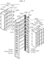
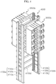
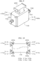
- FIGS. 3 and 4 are solid views of a movement guide device and a guide device in accordance with an exemplary embodiment.
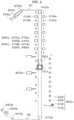
- FIG. 5 is a schematic view illustrating a state in which a guide roll of the guide device is disposed to correspond to a spaced space between a plurality of frames in a direction in which the plurality of frames of the movement guide device are disposed.
- FIG. 6 is a schematic view illustrating a state in which the guide roll and a nozzle of the guide device are disposed to correspond to the spaced space between the plurality of frames in a direction in which first and second guide members of the movement guide device are disposed.
- FIG. 5 is a schematic view illustrating a state in which a guide roll of the guide device is disposed to correspond to a spaced space between a plurality of frames in a direction in which first and second guide members of the movement guide device are disposed.
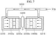
- FIG. 7 is a view for a blocked braking unit in accordance with an exemplary embodiment.
- FIG. 8 is a view illustrating a state in which first and second horizontal moving parts are connected to first and second guide rolls to explain their operations in accordance with an exemplary embodiment.
- FIG. 9 is a solid view of a plate and a moving cart for moving the plate in accordance with an exemplary embodiment.
- FIG. 10 is a top view illustrating a coupled relationship between the moving cart and the movement guide device in accordance with an exemplary embodiment.
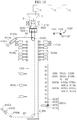
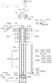
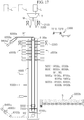
- FIGS. 11 to 17 are conceptual views for explaining a vertical semi-continuous casting method using the vertical semi-continuous casting equipment in accordance with an exemplary embodiment.
- vertical semi-continuous casting equipment in accordance with an exemplary embodiment includes a tundish T receiving molten steel from a ladle L to temporarily store the molten steel, a mold M receiving the molten steel from the tundish T to primarily solidify the molten steel, a first stirring device 2100 disposed outside the mold M to stir the molten steel within the mold M, a foot roll 3000 disposed under the mold M to guide and assist drawing of a slab S from the mold M, a plate 6000 that is vertically movable and draws the slab S from the mold M, a movement guide device 4000 disposed under the mold M and the foot roll 3000 to extend in a direction perpendicular to the ground so that the slab S and the plate 6000 stably descend, and a guide device 5000 in which a pair of guide parts 5000a and 5000b including a plurality of guide rolls 5100a and 5100b that are disposed to be arranged in the extension direction of the movement guide device 4000
- the vertical casting equipment includes a moving cart 7000 disposed inside the movement guide device 4000 to support the plate 6000 and being elevatable in the extension direction of the movement guide device 4000 and a plate moving device 8000 connected too the moving cart 7000 to provide elevation driving force to the moving cart 7000.
- the vertical casting equipment includes an oscillation generation device (not shown) disposed outside the mold M to oscillate the mold M, a separation device 9000a disposed on one side of the movement guide device 4000 to push the cast slab S and separate the slab S from the plate 6000, and an unloading device 9000b disposed on the other side of the movement guide device 400 to face the separation device 9000a, the unloading device 9000b vertically supporting the slab S by an operation of the separation device 9000a and horizontally rotating to unload the slab S to the outside.
- an oscillation generation device (not shown) disposed outside the mold M to oscillate the mold M
- a separation device 9000a disposed on one side of the movement guide device 4000 to push the cast slab S and separate the slab S from the plate 6000
- an unloading device 9000b disposed on the other side of the movement guide device 400 to face the separation device 9000a
- the vertical casting equipment include a second stirring device 2200 disposed above one side of the movement guide device 4000 or the pair of guide parts 5000a and 5000b to stir non-solidified molten steel of the slab S drawn from the mold M or non-solidified molten steel of the slab S during the solidification and a heating device 2300 moving between the foot roll 3000 and the movement guide device 4000 to heat a top area of the cast slab S.
- the ladle L, the tundish T, the mold M, the oscillation device (not shown), and the foot roll 3000 are the same as those of the general casting equipment, and thus, their detailed descriptions will be omitted, or the above-described components will be simply described.
- the vertical casting equipment including the above-described constituents in accordance with an exemplary embodiment may be called vertical semi-continuous casting equipment in that slabs are continuously cast through the plurality of ladles, and then the casting is finished.
- the mold M may cool and solidify molten liquid steel supplied from the tundish T to continuously cast a slab S having a rectangular section.
- the mold M has a cylindrical shape that has an inner space and is opened upward and downward. That is, the mold M may have a shape corresponding to that of the slab S to be cast, for example, a rectangular section.
- the mold M has a pair of shot side and long side and has a space with a rectangular section therein. Of cause, the mold M may vary in shape and size according to the shape of the slab S to be cast.
- the first stirring device 2100 is disposed around the outside of the mold M to stir molten steel within the mold M.
- the first stirring device 2100 in accordance with an exemplary embodiment may be an electro magnetic stirrer (EMS) for generating magnetic fields in the molten steel to stir the molten steel.
- EMS electro magnetic stirrer
- an initially solidified layer of the slab S may be uniform, and also, equiaxed grain within the slab S may increase by a uniform temperature of the molten steel within the mold M to improve internal quality of the slab S.
- the first stirring device 2100 is not limited to the above-described electro magnetic stirrer (EMS).
- EMS electro magnetic stirrer
- various units that are capable of stirring the molten steel within the mold M may be applied.
- the plate 6000 is inserted into the mold M before the casting to close the lower opening of the mold M. After the casting starts, the plate 6000 supports the slab S that is primarily solidified to descend, thereby drawing the slab S from the mold M. A portion or the whole of the plate 6000 may be inserted into the mold M before the molten steel is introduced into the mold M. Then, when the molten steel is introduced into the mold M to start the primary solidification of the molten steel, the plate 6000 gradually descends. In the state in which the plate 6000 is inserted into the mold M, an air gap between an outer circumferential surface of the plate 6000 and an inner wall of the mold M may be sealed.
- a special groove may be defined in the plate 6000 so that the slab S is easily drawn and easily separated from the plate 6000 after the solidification of the slab S is completed.
- the movement guide device 4000 is disposed to extend from a lower portion of the mold M in the vertical casting direction of the slab S so that the slab S, the plate 6000, and the moving cart 7000 stably move.
- the movement guide device 4000 includes a guide body 4100 extending in a vertical direction and having an inner space along which the slab S drawn from the mold M, the plate 6000, and the moving cart 7000 move in a vertical direction, i.e., an upward/downward direction, a plurality of openings 4200a and 4200b that are defined in the guide body 4100 and arranged to be spaced apart from each other in the vertical direction from both side direction of the guide body 4100 facing the pair of guide parts 5000a and 5000b, and guide members 4300a and 4300b disposed on an inner wall of the guide body 4100 in the vertical extension direction to assist the movement of the moving cart 7000.
- the guide body 4100 may be a unit for allowing the slab S, the plate 6000, and the moving cart 7000 to stably move in the vertical direction.
- the guide body 4100 has an inner space that extends in the vertical direction and is opened upward and downward.
- the guide body 4100 has a section with an approximate shape corresponding to that of the slab S or the mold M. For example, when the slab S having a rectangular section is manufactured, the guide body 4100 may have a hollow with a rectangular section.
- the guide body 4100 includes first and second support members 4100a and 4100b vertically extending from positions corresponding to both short sides of the mold M or the slab S and disposed to face each other and a plurality of first and second frames 4100c and 4100d disposed on positions corresponding to both long sides of the mold M or the slab S to extend in a direction crossing or perpendicular to in the extension direction of the first and second support members 4100a and 4100b and arranged to be spaced apart from each other in the extension direction of the first and second support members 4100a and 4100b.
- a spaced space between the first frames 4100c disposed to be spaced apart from each other may be the first opening 4200a through which the first guide roll 5100a of the first guide part 5000a that will be described below in detail passes
- a spaced space between the second frames 4100d disposed to be spaced apart from each other may be the second opening 4200b through which the second guide roll 5100b of the second guide part 5000b that will be described below in detail passes.
- the plurality of first openings 4200a are vertically arranged to be spaced apart from each other at positions corresponding to one long side of the mold M or the slab S
- the plurality of second openings 4200b are vertically arranged to be spaced apart from each other at positions corresponding to the other long side of the mold M or the slab S.
- the unloading device 9000b is disposed outside one side of both long sides of the guide body 4100, and the separation device 9000a is disposed outside the other side of both long sides of the guide body 4100.
- the separation device 9000a is disposed outside the first frame 4100c of the guide body 4100, and the unloading device 9000b is disposed outside the second frame 4100d.
- first and second support members 4100a and 4100b of the movement guide device 4000 in accordance with an exemplary embodiment has a section with the same shape as " " that is a consonant in Korean Alphabet.
- the first support member 4100a includes a pair of first supports 4110a and 4120a that vertically extend and are disposed to be spaced apart from each other in a direction of the short side of the mold M or the slab S and a plurality of first connection members 4130a that connect the pair of first supports 4110a and 4120a to each other and are arranged to be spaced apart from each other in the extension direction of the first supports 4110a and 4120a.
- each of the pair of first supports 4110a and 4120a in accordance with an exemplary embodiment has a " " or " " shape that is a consonant in Korean Alphabet.
- each of the pair of first supports 4110a and 4120a includes first members 4111 and 4121 extending in a direction corresponding to the short side direction of the slab S and second members 4112 and 4122 extending in a direction corresponding to the long side direction of the slab S.
- the first members 4111 and 4121 and the second members 4112 and 4122 are connected to each other in directions crossing or perpendicular to each other.
- the two first members 4111 and 4121 constituting each of the pair of first supports 4110a and 4120a are disposed to be spaced apart from each other.
- the second support member 4100b may have the same shape and constituent as the above-described first support member 4100a.
- the second support member 4100b includes a pair of second supports 4110b and 4120b that vertically extend and are disposed to face the pair of first supports 4110a and 4120a of the first support member 4100a and a plurality of second connection members 4130b that connect the pair of second supports 4110b and 4120b to each other and are arranged to be spaced apart from each other in the extension direction of the second supports 4110b and 4120b.
- each of the pair of second supports 4110b and 4120b in accordance with an exemplary embodiment has a " " or " " shape that is a consonant in Korean Alphabet.
- each of the pair of second supports 4110b and 4120b includes first members 4111 and 4121 extending in a direction corresponding to the short side direction of the slab S and second members 4112 and 4122 extending in a direction corresponding to the long side direction of the slab S.
- the first members 4111 and 4121 and the second members 4112 and 4122 are connected to each other in directions crossing or perpendicular to each other.
- the two first members 4111 and 4121 constituting each of the pair of first supports 4110a and 4120a are disposed to be spaced apart from each other.
- the separation device 9000a disposed outside one side of the guide body of the movement guide device 4000 pushes the slab S in an outer direction of the other side of the guide body 4100 to seat the slab S on the unloading device 9000b. That is, the cast slab S is unloaded in the direction of the other side of the guide body 4100.
- the plurality of second frames 4100d disposed in the direction of the other side of the guide body 4100 on which the unloading device 9000b is disposed are not arranged up to lower portions of the first and second support members 4100a and 4100b, but arranged up to an upper portion of the unloading device 9000b that vertically stands up.
- a region defined under the lowermost second frame 4100d of the plurality of second frames 4100d in the guide body 4100 may be defined in a space in which the slab S is separated from the movement guide device 4000.
- the guide members 4300a and 4300b vertically extend inward from the first and second support members 4100a and 4100b to guide the vertical movement of the moving cart 7000, respectively. That is, the first guide member 4300a is disposed inside the first support member 4100a, and the second guide member 4300b is disposed inside the second support member 4100b.
- Each of the first and second guide members 4300a and 4300b in accordance with an exemplary embodiment may have a rail shape, but is not limited thereto. For example, various units that are capable of guiding the movement of the moving cart 700 may be applied.
- the first guide member 4300a is disposed on each of the pair of first supports 4110a and 4120a constituting the first support member 4100a
- the second guide member 4300b is disposed each of the pair of second supports 4110b and 4120b constituting the second support member 4100b.
- the first guide member 4300a is disposed on an inner surface of each of the first members 4111 and 4121 and the second members 4112 and 4122 respectively constituting the pair of first supports 4110a and 4120a
- the second guide member 4300b is disposed on an inner surface of each of the first members 4111 and 4121 and the second members 4112 and 4122 respectively constituting the pair of second supports 4110b and 4120b.
- the guide device 5000 may operate to support an outer surface of the slab S that is drawn from the mold M by the plate 6000, and then to assist the descending of the slab S and inject the cooling water onto the descending slab S, thereby secondarily cooling the slab S.
- the guide device 5000 in accordance with an exemplary embodiment includes a first guide part 5000a disposed on one side of the movement guide device 4000 and a second guide part 5000b disposed on the other side of the movement guide device 4000 to face the first guide part 5000a.
- Each of the first and second guide parts 5000a and 5000b is disposed to face the long side of the descending slab S or each of the first and second frames 4100c and 4100d of the movement guide device 4000.
- the first guide part 5000a is disposed in a direction that faces one long side of the slab S or the first frame 4100c of the movement guide device 4000
- the second guide part 5000b is disposed in a direction that faces the other long side of the slab S or the second frame 4100d.
- the first guide part includes a plurality of first guide rolls 5100a vertically arranged to be spaced apart from each other at positions facing the first opening 4200a of the movement guide device 4000 and support one long side of the descending slab S, a first roll driving unit 5200a connected to each of the plurality of first guide rolls 5100a to allow the first guide rolls 5100a to easily rotate and move horizontally or forward/backward, a first braking unit 5300a connected to each of the plurality of first guide rolls 5100a to apply braking force to the first guide rolls 5100a, thereby to adjust rotation force of the first guide rolls 5100a, a plurality of nozzles 5400a vertically spaced apart from each other between the plurality of first guide rolls 5100a to inject the cooling water onto the slab S descending into the movement guide device 4000, and a first body 5500a disposed to support and fix the plurality of first guide rolls 5100a, the plurality of first roll driving units 5200a, the plurality of first nozzles 5400a.
- the second guide part includes a plurality of second guide rolls 5100b vertically arranged to be spaced apart from each other at positions facing the second opening 4200b of the movement guide device 4000 and support the other long side of the descending slab S, a second roll driving unit 5200b connected to each of the plurality of second guide rolls 5100b to allow the second guide rolls 5100b to easily rotate and move horizontally or forward/backward, a second braking unit 5300b connected to each of the plurality of second guide rolls 5100b to apply braking force to the second guide rolls 5100b, thereby to adjust rotation force of the second guide rolls 5100b, a plurality of nozzles 5400b vertically spaced apart from each other between the plurality of second guide rolls 5100b to inject the cooling water onto the slab S descending into the movement guide device 4000, and a second body 5500b disposed to support and fix the plurality of second guide rolls 5 100b, the plurality of second roll driving units 5200b, the plurality of second nozzles 5400b.
- the first guide roll 5100a extends in a direction corresponding to one long side of the mold M or the slab S to rotate by the movement of the slab S. Also, the plurality of first guide rolls 5100a are disposed to correspond to the plurality of first openings 4200a that are vertically arranged, respectively. That is, each of the plurality of first guide rolls 5100a is disposed to correspond to the spaced space (the first opening 4200a) between the plurality of first frames 4100c that are vertically arranged. The first guide roll 5100a move horizontally or forward/backward to pass through the first opening 4200a by the first roll driving unit 5200a.
- the second guide roll 5100b extends in a direction corresponding to the other long side of the mold M or the slab S to rotate. Also, the plurality of second guide rolls 5100b are disposed to correspond to the plurality of second openings 4200b that are vertically arranged, respectively. That is, each of the plurality of second guide rolls 5100b is disposed to correspond to the spaced space (the second opening 4200b) between the plurality of second frames 4100d that are vertically arranged. The second guide roll 5100b move horizontally or forward/backward to pass through the second opening 4200b by the second roll driving unit 5200b.
- the first roll driving unit 5200a, the second roll driving unit 5200b, the first braking unit 5300a, and the second braking unit 5300b have the same constituent and structure, thus, the first driving units 5200a and the first braking unit 5300a will be described, and description with respect to the second roll driving unit 5200b and the second braking unit 5300b will be omitted or simplified.
- the first roll driving unit 5200a includes a pair of first support blocks 5210a connected to one end and the other end of the first guide roll 5100a and a first horizontal moving part 5220a connected to each of the pair of first support blocks 5210a to provide driving force for the horizontal or forward/backward movement.
- the pair of first support blocks 5210a may be connected to one end and the other end of the first guide roll 5100a, and a unit such as a bearing for smooth rotation of the first guide roll 5100a may be disposed in each of the pair of first support blocks 5210a. That is, the bearing is disposed in each of the pair of first support blocks 5210a, and one end and the other end of the first guide roll 5100a are connected to the bearing disposed in the first support block 5210.
- the first support block 5210a covers the bearing and the one end and the other end of the first guide roll 5100a connected to the bearing.
- the first and second horizontal moving parts 5220a and 5220b may horizontally move the first and second guide rolls 5100a and 5100b according to a thickness of the slab S to be cast to adjust a distance between the first and second guide rolls 5100a and 5100b.
- the pair of first horizontal moving part 5220a may be respectivley connected to the pair of first support blocks 5210a to provide horizontal driving force, i.e., forward/backward moving force to the pair of first support blocks 5210a, and the pair of second horizontal moving part 5220b may be respectively connected to the pair of second support blocks 5210a to provide horizontal moving force, i.e., forward/backward moving force to the pair of second support blocks 5210b.
- each of the first and second horizontal moving parts 5220a and 5220b includes driving shafts 5221a and 5221b connected to the support blocks 5210a and 5210b to move forward and backward and driving sources 5222a and 5222b for moving the driving shafts 5221a and 5221b forward and backward.
- Each of the first and second horizontal moving parts 5220a and 5220b in accordance with an exemplary embodiment may be a hy7draulic cylinder, but is not limited thereto.
- various units that are capable of moving the first and second guide rolls 5100a and 5100b forward and backward may be applied.
- the first and second guide rolls 5100a and 5100b support one surface and the other surface of the descending slab S that is drawn from the mold M to rotate by the descending force of the slab S.
- the mold M may be oscillated by using a separate oscillation device to prevent the molten stall from being stuck on the inner wall of the mold M during the casting.
- the slab S drawn from the mold M may be vertically oscillated or shaken.
- the casting speed of the slab S may not be controlled to a designated or set speed due to the shaking of the slab S.
- the slab S may be cast at an unstable or inaccurate casting speed. This may deteriorate surface quality of the slab S and cause casting accidents.
- first and second braking units 5300a and 5300b may be respectivley provided on the first and second guide rolls 5100a and 5100b to control the rotation force of the first and second guide rolls 5100a and 5100b that rotate by the descending force of the slab S, thereby preventing the slab S from being shaken.
- Each of the first and second braking units 5300a and 5300b in accordance with an exemplary embodiment may be provided as a hydraulic disc brake to adjust a hydraulic pressure, thereby controlling the braking force.
- the hydraulic pressure and the braking force of each of the first and second braking units 5300a and 5300b may be adequately adjusted according to the casting speed and the intensity of the oscillation.
- the first and second braking units 5300a and 5300b may operate to add predetermined braking force to the first and second guide rolls 5100a and 5100b, thereby controlling the rotation force of each of the first and second guide rolls 5100a and 5100b.
- the first and second guide rolls 5100a and 5100b may not rotate by being synchronized with the descending speed of the plate 6000.
- the first and second guide rolls 5100a and 5100b may apply force to the slab S to interrupt the vertical movement of the slab S, thereby preventing the slab S from being shaken.
- each of the first and second braking units 5300a and 5300b includes a housing 5310 having an inner space, a disc 5320 connected to the guide rolls 5100a and 5100b to rotate together with the guide rolls 5100a and 5100b, first and second pads 5330a and 5330b disposed to be respectivley spaced apart from one surface and the other surface of the disc 5320, first and second pistons 5400a and 5400b disposed in the housing 5310 and respectively connected to rear portions of the first and second pads 5330a and 5330b to move forward and backward, and a supply tube 5500 connected to the housing 5310 to supply hydraulic oil into the housing 5310.
- a front side of each of the first and second pads 5330a and 5330b and a front side of each of the first and second pistons 5400a and 5400b may be a direction in which the disc 5320 is disposed, and a rear side may be an opposite direction.
- the supply tube 5500 is connected to a main body to supply oil to a rear side of each of the first and second pistons 5400a and 5400b.
- the first and second pistons 5400a and 5400b may advance to a disc direction, and thus, the first and second pads 5330a and 5330b may contact the disc.
- the first and second pads 5330a and 5330b respectively contact one surface and the other surface of the rotating disc, braking force may be applied to the disc by friction force.
- the braking force may be applied to the guide rolls 5100a and 5100b connected to the disc.
- each of the first and second braking units 5300a and 5300b in accordance with an exemplary embodiment is provided as the hydraulic disc brake, the present disclosure is not limited thereto.
- various units that are capable of applying the braking force to the rotation of the first and second guide rolls 5100a and 5100b to control the rotation may be applied.
- the plate moving device 8000 may be a unit for allowing the plate 600 to ascend or descend.
- the plate moving device 800 in accordance with an exemplary embodiment may be a driving unit using a wire or a wire rope.
- the plate moving device 8000 in accordance with an exemplary embodiment includes a first driving unit 8000a disposed in an upper portion of the movement guide device 4000, a second driving unit 8000b disposed in a lower portion of the movement guide device 4000, a first wire W1 wound to connect a first sheave 7200 disposed on the moving cart 7000 to the first driving unit 8000a, and a second wire W2 wound to connect a second sheave 7300 to the second driving unit 8000b.
- the first driving unit 8000a includes a pair of rotatable first winches 8100a disposed to face each other outside the upper portion of the movement guide device and around which the first wire W1 is wound, a rotatable first drum 8300a around which the first wire W1 is wound, and a first motor 8400a connected to the first drum 8300a to provide rotation force. Also, the first driving unit 8000a includes a rotatable first direction adjusting part 8200a disposed between the first winches 8100a and the first drum 8300a and around which the first wire W1 is wound to switch a direction.
- the pair of first winches 8100a may be disposed to face the first and second support members 4100a and 4100b outside the first and second support members 4100a and 4100b of the guide body 4100.
- the second driving unit 8000b includes a pair of rotatable second winches 8100b disposed to face each other outside the upper portion of the movement guide device and around which the first wire W1 is wound, a rotatable second drum 8300b around which the second wire W2 is wound, and a second motor 8400b connected to the second drum 8300b to provide rotation force.
- the second driving unit 8000b includes a rotatable first direction adjusting part 8200a disposed between the second winches 8100b and the second drum 8300b and around which the second wire W2 is wound to switch a direction.
- the pair of second winches 8100b may be disposed to face the first and second support members 4100a and 4100b outside the first and second support members 4100a and 4100b of the guide body 4100.
- the first driving unit 8000a may pull or unwind the first wire W1 to allow the moving cart 700 to ascend or descend.
- the second driving unit 8000b may allow the second wire W2 to have tension according to the ascending or descending of the moving cart, thereby allowing the plate 6000 and the moving cart 7000 to stably move.
- a unit in which the winch is provided to each of the first and second driving units 8000a and 8000b to wind or unwind the wires W1 and W2, thereby moving the plate 600 is described as an example.
- the first and second driving units 8000a and 8000b are not limited thereto.
- various units that are capable of moving the plate 6000, i.e., a hydraulic cylinder may be applied.
- the guide device 5000 includes the two guide parts 5000a and 500b, the present disclosure is not limited thereto.
- an additional guide part may be further provided according to various casting conditions and equipment constituents.
- the moving cart 7000 supports the plate 6000 and is disposed inside the movement guide device 4000 to ascend or descend along an extension direction of the movement guide device 4000 by the plate moving device 8000 that will be described below in detail.
- the moving cart 7000 includes a cart body 7100 supporting the plate 6000, a pair of rotatable first sheaves 7200 spaced apart from both side surfaces of the cart body 7100 in a direction facing the first and second support members 4100a and 4100b of the movement guide device 4000 and around which the first wire W1 is wound, a pair of rotatable second sheaves 7300 spaced apart from both outsides of the pair of first sheaves 7200 and around which the second wire W2 is wound, and gliding parts 7400a and 7400b respectively disposed on both side surfaces of an outer surface of the moving cart 7000, which face the first and second support members 4100a and 4100b and glided along the first and second guide members 4300a and 4300b.
- the first and second sheaves 7200 and 7300 are fixedly disposed to be connected to the movement guide body 4100 to move together with the ascending/descending cart body.
- the cart body 7100 may have a shape corresponding to that of the section of the movement guide device 4000, for example, a rectangular shape.
- the cart body 7100 may be elevated along the guide members 4300a and 4300b disposed inside the guide body 4100 and the movement guide device 4000.
- first and second gliding parts 7400a and 7400b that are capable of being glided along the first and second guide members 4300a and 4300b are disposed on outer surfaces of the moving cart 7000, which faces the first and second support members 4100a and 4100b, respectivley.
- the first and second gliding parts 7400a and 7400b are disposed at positions corresponding to the first and second guide members 4300a and 4300b on each of one surface and the other surface of the moving cart 700 facing the first and second support members 4100a and 4100b of the guide member 4100 of the movement guide device 4000.
- the gliding parts may be disposed at four corners on each of the one side and the other side of the moving cart 700.
- the first and second gliding parts 7400a and 7400b disposed on the moving cart 7000 may be disposed to be glided along the first and second guide members 4300a and 4300b.
- the plurality of first gliding parts 7400a may be disposed on the one surface of the moving cart 7000 and glided along the first guide member 4300a disposed on the first support member 4100a.
- the plurality of second gliding part may be disposed on the other surface of the moving cart 7000 and glided along the second guide member 4300b disposed on the second support member 4100b. That is to say, the first and second gliding parts 7400a and 7400b may be disposed on the four corners on each of the one surface and the other surface of the moving cart 7000.
- Each of the first and second gliding parts 7400 and 7400b includes a first gliding member 7411 and a second gliding member 7412.
- the first gliding member 7411 may be disposed closer to the corner than the second gliding member 7412.
- the first gliding member 7411 may be glided along the first and second guide members 4300a and 4300b disposed on the second members 4112 and 4122 respectively constituting the first and second support members 4100a and 4100b
- the second gliding member 7412 may be glided along the first and second guide members 4300a and 4300b disposed on the first members 4111 and 4121 respectively constituting the first and second support members 4100a and 4100b.
- a ball-shaped unit or various units that are capable of being glided along the guide member may be applied as each of the first and second gliding members 7411 and 7412 in accordance with an exemplary embodiment.
- the heating device 2300 may heat the top portion of the slab S before the slab S is unloaded to prevent the slab S from being solidified first from the top portion, thereby reducing the pipe defect on the top portion of the slab S.
- the heating device 2300 includes a heating body 2310 having a hollow with an opening through which the slab S passes and a heater 2320 disposed in the heating body 2310.
- the heating device 2300 in accordance with an exemplary embodiment may be an electro magnetic heater (EMH), and the heater may be an induction heating coil.
- EMH electro magnetic heater
- the unloading device 9000b may receive the slab S that is placed in a vertical state from the plate 6000 to rotate to a horizontal state.
- the unloading device 900b includes a first seating part 9100 supporting and seating a lower portion of the slab S that is in the vertical state and separated from the plate 6000, a second seating part 9200 extending in a direction crossing the first seating part 9100 and connected to the first seating part 9100 to face a side surface of the slab S, a plurality of rotatable unloading rollers 9300 arranged in the extension direction of the second seating part 9200, and a rotation driving part 9400 disposed to connect the first and second seating parts 9100 and 9200 to each other to rotate or tilt the unloading device 9000b.
- the separation device 9000a is disposed outside the movement guide device 4000 to face the unloading device 9000b and push the cast slab S toward the unloading device 9000b, thereby separating the slab S from the plate 600.
- the separation device 9000a may be provided in plurality and spaced apart from each other in a vertical direction or upward/downward direction with respect to the ground.
- the separation device 9000a in accordance with an exemplary embodiment may be provided as the hydraulic cylinder, but the present disclosure is not limited thereto. For example, various unit that are capable of pushing the slab S to the unloading device 9000b to separate the slab S from the plate 6000 may be applied.
- the moving cart 7000 ascends through the plate moving device 8000. Then, as illustrated in FIG. 11 , the plate 6000 is inserted into a lower side of the mold M to close the lower side of the mold M. That is, when the first winch 8100a rotates to pull the first wire W1, the moving cart 7000 and the plate 6000 ascend. Here, the plate 6000 moves to close the lower opening of the mold M. Also, the first and second horizontal moving parts 5220a and 5220b of the guide device 5000 operate to allow each of the first and second guide rolls 5100a and 5100b to move forward or backward according to a thickness of the slab S to be cast, thereby adjusting a spaced distance between the first and second guide rolls 5100a and 5100b.
- the ladle L in which the molten steel is accommodated moves above the tundish T to tap the molten steel of the ladle L to the tundish.
- the molten steel of the tundish T When the molten steel of the tundish T is supplied into the mold M through the nozzle, the molten steel is primarily solidified in the mold M. Here, the solidification of the molten steel starts on the plate 6000. While the molten steel is supplied into the mold M, the first stirring device 2100 disposed outside the mold M operates to stir the molten steel within the mold M. Also, a separate oscillation device oscillates the mold M to prevent the molten steel from being stuck on the inner wall of the mold M.
- the moving cart 7000 and the plate 6000 descend through the plate moving device 8000, as illustrated in FIG. 12 , the primarily solidified slab S is drawn from the mold M.
- the plate 6000 descends to cast a slab S having a predetermined length (see FIG. 13 ).
- the molten steel may be continuously supplied through the plurality of ladles L to perform the continuous casting.
- the slab S is cast as much as an amount of molten steel supplied from one ladle L in accordance with the related art, the slab S may be continuously cast as much as an amount of molten steel continuously supplied from at least two ladles L in accordance with an exemplary embodiment.
- the slab S cast and drawn from the mold M descends to pass through the inside of the movement guide device 4000 as illustrated in FIGS. 12 to 14 .
- the slab S descends in the state in which the side surface of the slab S is supported by the first and second guide rolls 5100a and 5100b, and the first and second guide rolls 5100a and 5100b rotate by the descending force of the slab S.
- the slab S is secondarily cooled by the cooling water injected from the plurality of first and second nozzles 5400a and 5400b.
- the second stirring device 2200 disposed outside each of the first and second guide parts 5000a and 5000b operates to stir the non-solidified molten steel on the top portion of the slab S, thereby minimizing the pipe defect.
- the braking units 5300a and 5300b are respectively disposed on the first and second guide rolls 5100a and 5100b to prevent the slab S from being shaken. That is, when the slab S is cast, the first and second braking units 5300a and 5300b may operate to add predetermined braking force to the first and second guide rolls 5100a and 5100b, thereby controlling the rotation force of each of the first and second guide rolls 5100a and 5100b.
- the first and second guide rolls 5100a and 5100b may apply force to the slab S to interrupt the vertical movement of the slab S, thereby preventing the slab S from being shaken. Also, the slab S, the plate 6000, and the moving cart 7000 descend to pass through the inside of the movement guide device 4000.
- the second winch 8100b tensionally supports the second wire W2 at the lower side of the plate 6000, the stable descending may be enabled.
- the heating device is disposed above the movement guide device 4000. Also, the plate 6000 and the moving cart 7000 ascend by a predetermined distance to allow the top portion of the slab S to be inserted into the opening of the heating device. Thereafter, when the heating device 2300 operates, the top portion of the slab S may be heated to minimize the pipe defect at the top portion of the slab S.
- the slab S descends up to an unloading position. That is, the top portion of the slab S may be disposed under the lowermost first frame 4100c of the plurality of first frames 4100c. Thereafter, when the separation device 9000a operates to push the slab S, the slab S moves to the unloading device 9000b that vertically stands up. Also, as illustrated in FIG. 17 , the unloading device 9000b may be tilt to allow the slab S to be placed in the horizontal direction, thereby unloading the slab S.
- the molten steel may be continuously supplied through the plurality of ladles L to continuously perform the vertical casting of the slab, thereby casting a thick slab S having a thickness of about 400 mm to about 1,000 mm. That is, in case of the casting of a very large-section slab having the very thick thickness, only the casting through one charging is performed as much as an amount of molten steel that supplied from one ladle L by using the vertical semi-continuous casting equipment due to the solidification characteristics and quality limitations, and then, the casting is finished.
- the guide device 5000 and the movement guide device 4000 may be disposed under the mold M, and the braking units 5300a and 5300b may be connected to the guide rolls 5100a and 5100b to control the rotation force of the guide rolls 5100a and 5100b.
- the slab having the length longer than that of the slab in accordance with the related art may stably descend, the shaking of the slab S may be prevented, and the casting speed may be stabilized. Therefore, since the vertical semi-continuous casting may be performed by using the molten steel supplied from the plurality of ladles L, but not one ladle L, to improve the productivity and recovery of the slab by more than two times.
- the molten steel may be continuously supplied through the plurality of ladles to continuously perform the vertical casting of the slab. That is, in the related art, only the casting through the one charging is performed by using an amount of molten steel supplied from one ladle, and then, the casting is finished.
- the slab may be unstable in movement to cause the casting accident.
- the guide device and the movement guide device may be disposed under the mold, and the braking unit may be connected to the guide roll to control the rotation force of the guide roll.
- the slab having the length longer than that of the slab in accordance with the related art may stably descend, the shaking of the slab may be prevented, and the casting speed may be stabilized. Therefore, since the vertical semi-continuous casting may be performed by using the molten steel supplied from the plurality of ladles, but not one ladle, to improve the productivity and recovery of the slab by more than two times.
Landscapes
- Engineering & Computer Science (AREA)
- Mechanical Engineering (AREA)
- Continuous Casting (AREA)
- Moulds For Moulding Plastics Or The Like (AREA)
Abstract
Description
- The present disclosure relates to vertical semi-continuous casting equipment and a vertical semi-continuous casting method using the same, and more particularly, to vertical semi-continuous casting equipment that is capable of improving productivity and recovery and a method semi-continuous casting method using the same.
- In casting of a slab having a thick thickness (about 400 mm to about 1,000 mm), since it is difficult to cast the slab by using general curved casting equipment, the slab may be cast by using vertical casting equipment, but not using the curved casting equipment. However, when a slab having a very thick thickness is cast, it takes a very long time to completely solidify the slab. Thus, in case of continuous casting, there is a limitation in that a vertical part of the equipment has a very long length. Thus, a vertical semi-continuous casting method, in which casting is finished after casting a slab S having a predetermined length, and then a slab S is cast through the next charging, is used.
- The vertical semi-continuous casting equipment using the vertical semi-continuous casting method includes a tundish T receiving molten steel supplied from a ladle L, a mold M continuously receiving the molten steel from the tundish T to solidify the molten steel, an
elevatable plate 10 inserted into the mold M during the casting and descending while supporting the slab S that is solidified in the mold M to draw the slab S from the mold M, and afoot roll 30 assisting and guiding the drawing of the slab S from the mold M. Also, the vertical semi-continuous casting equipment includes a heater disposed above the mold to heat an upper portion (top portion) of the slab S, thereby to minimize a pipe defect at the upper portion of the slab S. - In accordance with the casting method using the above-described vertical semi-continuous casting equipment, the molten steel is injected into the mold M in a state in which the
plate 10 is inserted to cover a lower opening of the mold M. The molten steel supplied into the mold M is solidified by cooling water flowing through the inside of a wall of the mold M. Here, when theplate 10 vertically descends, the slab S is drawn from the mold M. As described above, when the injection of the molten steel into the mold M and the descending of theplate 10 are continuously performed, the slab S having the predetermined length may be drawn from the mold S by thedescending plate 10. Also, when the slab S having the predetermined length is cast, the casting is finished, and the upper portion (top portion) of the slab S is heated by the heater. - In accordance with the vertical semi-continuous casting equipment, the casting is finished after the casting through one charging (or one heating) is performed, and then, casting through the next charging is prepared. That is, the slab S is cast as much as an amount of molten steel supplied from one ladle S to the tundish T, and then, the casting is finished. Thus, since casting through multi charging by supplying the molten steel from a plurality of ladles L to the tundish is not performed, productivity and recovery of the slab S may be deteriorated.
- (Patent Document 1) Korean Patent Registration No.
1272712 - The present disclosure provides vertical semi-continuous casting equipment that is capable of improving productivity and recovery and a vertical semi-continuous casting method using the same.
- The present disclosure also provide vertical semi-continuous casting equipment that is capable of vertically casting a slab having a length greater than that of a slab in accordance with the related art and a vertical semi-continuous casting method using the same.
- In accordance with an exemplary embodiment, vertical semi-continuous casting equipment includes: a mold configured to cool molten steel, thereby casting a slab; an elevatable plate descending while supporting a lower portion of the slab that is cast in the mold to draw the slab from the mold in a state in which the slab is disposed in a direction perpendicular to the ground; and a guide device disposed under the mold to support the slab drawn from the plate, the guide device being configured to guide the descending of the slab, wherein the guide device includes first and second guide parts including: a plurality of guide rolls respectively disposed on both sides of a moving path of the plate under the mold to support the slab moving by the plate and gu
- ide the movement of the slab; and a braking unit connected to each of the guide rolls to apply braking force to the guide roll that rotates by the movement of the slab.
- Each of the first and second guide parts may include a roll driving unit connected to each of the guide rolls to allow the guide roll to move forward or backward toward the moving path of the slab and the plate.
- The roll driving unit may include: a support block connected to an end of the guide roll; and a horizontal moving part connected to the support block to apply forward moving force and backward moving force.
- Each of the first and second guide parts may include a plurality of nozzles disposed between the plurality of guide rolls that are vertically arranged to inject cooling water to the slab.
- The vertical semi-continuous casting equipment may further include a movement guide device disposed under the mold to extend in the direction perpendicular to the ground and including a guide body having an inner space along which the slab and the plate move in the direction perpendicular to the ground, the movement guide device being configured to guide the movement of the slab and the plate, wherein the first and second guide parts may be disposed on one side and the other side of the movement guide device, respectivley.
- First openings vertically arranged to be spaced apart from each other may be defined in one surface of the guide body facing the first guide part, second openings vertically arranged to be spaced apart from each other may be defined in the other surface of the guide body facing the second guide part, the plurality of guide rolls of the first guide part may be arranged to correspond to the first openings, the plurality of guide rolls moving forward and backward to pass through the first openings by a horizontal driving part of the first guide part; and the plurality of guide rolls of the second guide part may be arranged to correspond to the second openings, the plurality of guide rolls moving forward and backward to pass through the second openings by a horizontal driving part of the second guide part.
- The guide body may include: first and second support members vertically extending in a direction crossing positions of the plurality of first and second openings, the first and second support members being disposed to face each other; a plurality of first frames extending in a direction crossing the extension direction of the first and second support members to connect the first support member to the second support member at one side of the first and second support members, the plurality of first frames being arranged to be spaced apart from each other in the extension direction of the first and second support members; and a plurality of second frames extending in a direction crossing the extension direction of the first and second support members to connect the first support member to the second support member at the other side of the first and second support members, the plurality of second frames being arranged to be spaced apart from each other in the extension direction of the first and second support members, wherein a spaced space between the first frames may be defined as the first opening, and a spaced space between the second frames may be defined as the second opening.
- The movement guide device may include a guide member disposed on an inner surface of each of the first and second support members of the guide body to extend along the extension direction of each of the first and second support members.
- The vertical semi-continuous casting equipment may further include a moving cart disposed in the inner space of the guide body to support the plate, the moving cart being elevated along the extension direction of the guide body.
- The vertical semi-continuous casting equipment may further include a plate moving device connected to the moving cart to elevate the moving cart.
- The moving cart may include: a cart body on which the plate is seated on an upper portion thereof; a pair of rotatable first sheaves disposed to be connected both side surfaces of the cart body; a pair of rotatable second sheaves disposed on one sides of the pair of fist sheaves, respectivley; and first and second gliding parts mounted on both side surfaces of the cart body, the first and second gliding parts being configured to be glided along the first and second guide members of the movement guide device.
- The plate moving device may include: a rotatable first winch disposed above the outside of the movement guide device; a first wire wound to connect the first sheaves of the moving cart to the first winch; a rotatable first drum around which the first wire wound around the first winch is wound; a first motor connected to the first drum to rotate the first drum; a rotatable second winch disposed under the outside of the movement guide device; a second wire wound to connect the second sheaves of the moving cart to the second winch; a rotatable second drum around which the second wire wound around the second winch is wound; and a second motor connected to the second drum to rotate the second drum.
- The vertical semi-continuous casting equipment may further include: an unloading device disposed outside the first frame of the guide body to receive the cast slab, thereby unloading the slab; and a separation device disposed outside the second frame to face the unloading device, the separation device being configured to push the cast slab disposed in the guide body toward the unloading device, thereby separating the slab from the plate.
- The lowermost first frame of the plurality of first frames that are arranged to be spaced apart from each other in the extension direction of the first and second support members may be disposed at a height higher than that of the unloading device to allow a region of the guide body, which is under the lowermost first frame, to be defined as a space in which the cast slab is unloaded from the guide body.
- The unloading device may receive the slab that is in the vertical state from the plate to rotate to a horizontal state.
- The vertical semi-continuous casting equipment may further include a first stirring device disposed around the outside of the mold to stir the molten steel within the mold.
- The vertical semi-continuous casting equipment may further include a second stirring device disposed around an upper portion of the movement guide device or in the guide roll outside the movement guide device to stir non-solidified molten steel of the slab during or after the casting.
- The vertical semi-continuous casting equipment may further include a heating device that is movable between the mold and the movement guide device, wherein, when a top portion of the slab within the movement guide device ascends to be disposed between the mold and the movement guide device after the drawing of the slab from the mold is finished, the heating device may heat the top portion of the slab.
- In accordance with another exemplary embodiment, a vertical semi-continuous casting method includes: allowing a plate to ascend, thereby closing a lower opening of a mold; supplying molten steel into the mold to cool the molten steel in the mold; allowing the plate to descend in a direction perpendicular to the ground, thereby continuously drawing a slab from the mold; and oscillating the mold, wherein the continuously drawing of the slab includes: allowing the slab to descend between a plurality of first guide rolls arranged in the direction perpendicular to the ground at a lower side of the mold and a plurality of second guide rolls disposed to face the plurality of first guide rolls at the lower side of the mold; and applying braking force to each of the plurality of first guide rolls and the plurality of second guide rolls according to a casting speed while the slab descends between the plurality of first guide rolls and the plurality of second guide rolls.
- The vertical semi-continuous casting method may further include injecting cooling water to the slab while the slab moves between the first guide rolls and the second guide rolls.
- Before the plate descends, each of the first and second guide rolls may horizontally move to adjust a distance between the first and second guide rolls according to a thickness of the slab to be cast so that the first guide rolls contact one surface of the slab, and the second guide rolls contact the other surface of the slab.
- A movement guide device having an inner space and extending in the direction perpendicular to the ground may be disposed under the mold, first and second openings may be defined in one surface and the other surface of the movement guide device to correspond to the plurality of first and second guide rolls, respectively, and before the slab is drawn from the mold, the first guide rolls may horizontally move to pass through the first opening according to the thickness of the slab, and the second guide rolls may horizontally move to pass through the second opening according to the thickness of the slab.
- The slab continuously drawn by the plate may move to pass through the inside of the movement guide device.
- The vertical semi-continuous casting method may further include operating the first stirring device disposed around the outside of the mold to stir the molten steel within the mold.
- The vertical semi-continuous casting method may further include stirring non-solidified molten steel of the slab that moves into the movement guide device during the casting or is being solidified after the casting by using a second stirring device disposed on each of one side of the first guide roll and the other side of the second guide roll.
- When the casting of the slab is finished, a heating device may move between the mold and the first and second guide rolls, and a top portion of the slab may ascend to be disposed between the first and second guide rolls and be heated by using the heating device.
- Exemplary embodiments can be understood in more detail from the following description taken in conjunction with the accompanying drawings, in which:
-
FIG. 1 is a conceptual view of general vertical semi-continuous casting equipment; -
FIG. 2 is a conceptual view of vertical semi-continuous casting equipment in accordance with an exemplary embodiment; -
FIGS. 3 and4 are solid views of a movement guide device and a guide device in accordance with an exemplary embodiment; -
FIG. 5 is a schematic view illustrating a state in which a guide roll of the guide device is disposed to correspond to a spaced space between a plurality of frames in a direction in which the plurality of frames of the movement guide device are disposed; -
FIG. 6 is a schematic view illustrating a state in which the guide roll and a nozzle of the guide device are disposed to correspond to the spaced space between the plurality of frames in a direction in which first and second guide members of the movement guide device are disposed; -
FIG. 7 is a view for a blocked braking unit in accordance with an exemplary embodiment; -
FIG. 8 is a view illustrating a state in which first and second horizontal moving parts are connected to first and second guide rolls to explain their operations in accordance with an exemplary embodiment; -
FIG. 9 is a solid view of a plate and a moving cart for moving the plate in accordance with an exemplary embodiment; -
FIG. 10 is a top view illustrating a coupled relationship between the moving cart and the movement guide device in accordance with an exemplary embodiment; and -
FIGS. 11 to 17 are conceptual views for explaining a vertical semi-continuous casting method using the vertical semi-continuous casting equipment in accordance with an exemplary embodiment. - Hereinafter, specific embodiments will be described in detail with reference to the accompanying drawings. The present invention may, however, be embodied in different forms and should not be construed as limited to the embodiments set forth herein. Rather, these embodiments are provided so that this disclosure will be thorough and complete, and will fully convey the scope of the present invention to those skilled in the art.
-
FIG. 2 is a conceptual view of vertical semi-continuous casting equipment in accordance with an exemplary embodiment.FIGS. 3 and4 are solid views of a movement guide device and a guide device in accordance with an exemplary embodiment.FIG. 5 is a schematic view illustrating a state in which a guide roll of the guide device is disposed to correspond to a spaced space between a plurality of frames in a direction in which the plurality of frames of the movement guide device are disposed.FIG. 6 is a schematic view illustrating a state in which the guide roll and a nozzle of the guide device are disposed to correspond to the spaced space between the plurality of frames in a direction in which first and second guide members of the movement guide device are disposed.FIG. 7 is a view for a blocked braking unit in accordance with an exemplary embodiment.FIG. 8 is a view illustrating a state in which first and second horizontal moving parts are connected to first and second guide rolls to explain their operations in accordance with an exemplary embodiment.FIG. 9 is a solid view of a plate and a moving cart for moving the plate in accordance with an exemplary embodiment.FIG. 10 is a top view illustrating a coupled relationship between the moving cart and the movement guide device in accordance with an exemplary embodiment.FIGS. 11 to 17 are conceptual views for explaining a vertical semi-continuous casting method using the vertical semi-continuous casting equipment in accordance with an exemplary embodiment. - Referring to
FIG. 2 , vertical semi-continuous casting equipment in accordance with an exemplary embodiment includes a tundish T receiving molten steel from a ladle L to temporarily store the molten steel, a mold M receiving the molten steel from the tundish T to primarily solidify the molten steel, afirst stirring device 2100 disposed outside the mold M to stir the molten steel within the mold M, afoot roll 3000 disposed under the mold M to guide and assist drawing of a slab S from the mold M, aplate 6000 that is vertically movable and draws the slab S from the mold M, amovement guide device 4000 disposed under the mold M and thefoot roll 3000 to extend in a direction perpendicular to the ground so that the slab S and theplate 6000 stably descend, and aguide device 5000 in which a pair ofguide parts movement guide device 4000 are disposed to face both sides of themovement guide device 4000 so that the slab S stably descends, theguide device 5000 injecting cooling water onto the primarily solidified slab S to secondarily solidify the slab S. - Also, the vertical casting equipment includes a moving
cart 7000 disposed inside themovement guide device 4000 to support theplate 6000 and being elevatable in the extension direction of themovement guide device 4000 and aplate moving device 8000 connected too the movingcart 7000 to provide elevation driving force to the movingcart 7000. Also, the vertical casting equipment includes an oscillation generation device (not shown) disposed outside the mold M to oscillate the mold M, aseparation device 9000a disposed on one side of themovement guide device 4000 to push the cast slab S and separate the slab S from theplate 6000, and anunloading device 9000b disposed on the other side of the movement guide device 400 to face theseparation device 9000a, theunloading device 9000b vertically supporting the slab S by an operation of theseparation device 9000a and horizontally rotating to unload the slab S to the outside. - Also, the vertical casting equipment include a
second stirring device 2200 disposed above one side of themovement guide device 4000 or the pair ofguide parts heating device 2300 moving between thefoot roll 3000 and themovement guide device 4000 to heat a top area of the cast slab S. - In the vertical casting equipment in accordance with an exemplary embodiment, the ladle L, the tundish T, the mold M, the oscillation device (not shown), and the
foot roll 3000 are the same as those of the general casting equipment, and thus, their detailed descriptions will be omitted, or the above-described components will be simply described. - The vertical casting equipment including the above-described constituents in accordance with an exemplary embodiment may be called vertical semi-continuous casting equipment in that slabs are continuously cast through the plurality of ladles, and then the casting is finished.
- The mold M may cool and solidify molten liquid steel supplied from the tundish T to continuously cast a slab S having a rectangular section. The mold M has a cylindrical shape that has an inner space and is opened upward and downward. That is, the mold M may have a shape corresponding to that of the slab S to be cast, for example, a rectangular section. In detail, the mold M has a pair of shot side and long side and has a space with a rectangular section therein. Of cause, the mold M may vary in shape and size according to the shape of the slab S to be cast.
- The
first stirring device 2100 is disposed around the outside of the mold M to stir molten steel within the mold M. Thefirst stirring device 2100 in accordance with an exemplary embodiment may be an electro magnetic stirrer (EMS) for generating magnetic fields in the molten steel to stir the molten steel. As the molten steel within the mold M is stirred by thefirst stirring device 2100, an initially solidified layer of the slab S may be uniform, and also, equiaxed grain within the slab S may increase by a uniform temperature of the molten steel within the mold M to improve internal quality of the slab S. - Of cause, the
first stirring device 2100 is not limited to the above-described electro magnetic stirrer (EMS). For example, various units that are capable of stirring the molten steel within the mold M may be applied. - The
plate 6000 is inserted into the mold M before the casting to close the lower opening of the mold M. After the casting starts, theplate 6000 supports the slab S that is primarily solidified to descend, thereby drawing the slab S from the mold M. A portion or the whole of theplate 6000 may be inserted into the mold M before the molten steel is introduced into the mold M. Then, when the molten steel is introduced into the mold M to start the primary solidification of the molten steel, theplate 6000 gradually descends. In the state in which theplate 6000 is inserted into the mold M, an air gap between an outer circumferential surface of theplate 6000 and an inner wall of the mold M may be sealed. Thus, when the molten steel is introduced into the mold M, leakage of the molten steel through a fine spaced space between theplate 6000 and the cooling mold M may be prevented. Also, a special groove may be defined in theplate 6000 so that the slab S is easily drawn and easily separated from theplate 6000 after the solidification of the slab S is completed. - Referring to
FIGS. 2 to 6 , themovement guide device 4000 is disposed to extend from a lower portion of the mold M in the vertical casting direction of the slab S so that the slab S, theplate 6000, and the movingcart 7000 stably move. Themovement guide device 4000 includes a guide body 4100 extending in a vertical direction and having an inner space along which the slab S drawn from the mold M, theplate 6000, and the movingcart 7000 move in a vertical direction, i.e., an upward/downward direction, a plurality ofopenings guide parts guide members cart 7000. - The guide body 4100 may be a unit for allowing the slab S, the
plate 6000, and the movingcart 7000 to stably move in the vertical direction. The guide body 4100 has an inner space that extends in the vertical direction and is opened upward and downward. The guide body 4100 has a section with an approximate shape corresponding to that of the slab S or the mold M. For example, when the slab S having a rectangular section is manufactured, the guide body 4100 may have a hollow with a rectangular section. - Hereinafter, a structure of the guide body 4100 will be described in more detail.
- Referring to
FIGS. 3 to 6 , the guide body 4100 includes first andsecond support members second frames second support members second support members first frames 4100c disposed to be spaced apart from each other may be thefirst opening 4200a through which thefirst guide roll 5100a of thefirst guide part 5000a that will be described below in detail passes, and a spaced space between thesecond frames 4100d disposed to be spaced apart from each other may be thesecond opening 4200b through which thesecond guide roll 5100b of thesecond guide part 5000b that will be described below in detail passes. That is, the plurality offirst openings 4200a are vertically arranged to be spaced apart from each other at positions corresponding to one long side of the mold M or the slab S, and the plurality ofsecond openings 4200b are vertically arranged to be spaced apart from each other at positions corresponding to the other long side of the mold M or the slab S. - The
unloading device 9000b is disposed outside one side of both long sides of the guide body 4100, and theseparation device 9000a is disposed outside the other side of both long sides of the guide body 4100. In the vertical semi-continuous casting equipment in accordance with an exemplary embodiment, theseparation device 9000a is disposed outside thefirst frame 4100c of the guide body 4100, and theunloading device 9000b is disposed outside thesecond frame 4100d. - Each of the first and
second support members movement guide device 4000 in accordance with an exemplary embodiment has a section with the same shape as "" that is a consonant in Korean Alphabet. In more detail, the
first support member 4100a includes a pair offirst supports first connection members 4130a that connect the pair offirst supports first supports - Here, each of the pair of
first supports " or " " shape that is a consonant in Korean Alphabet. In more detail, each of the pair of
first supports first members second members first members second members first members first supports - The
second support member 4100b may have the same shape and constituent as the above-describedfirst support member 4100a. Thesecond support member 4100b includes a pair ofsecond supports first supports first support member 4100a and a plurality ofsecond connection members 4130b that connect the pair ofsecond supports - Here, each of the pair of
second supports " or "" shape that is a consonant in Korean Alphabet. In more detail, each of the pair ofsecond supports first members second members first members second members first members first supports - When the casting of the slab S is finished, the
separation device 9000a disposed outside one side of the guide body of themovement guide device 4000 pushes the slab S in an outer direction of the other side of the guide body 4100 to seat the slab S on theunloading device 9000b. That is, the cast slab S is unloaded in the direction of the other side of the guide body 4100. Thus, the plurality ofsecond frames 4100d disposed in the direction of the other side of the guide body 4100 on which theunloading device 9000b is disposed are not arranged up to lower portions of the first andsecond support members unloading device 9000b that vertically stands up. Thus, a region defined under the lowermostsecond frame 4100d of the plurality ofsecond frames 4100d in the guide body 4100 may be defined in a space in which the slab S is separated from themovement guide device 4000. - The
guide members second support members cart 7000, respectively. That is, thefirst guide member 4300a is disposed inside thefirst support member 4100a, and thesecond guide member 4300b is disposed inside thesecond support member 4100b. Each of the first andsecond guide members - In an exemplary embodiment, the
first guide member 4300a is disposed on each of the pair offirst supports first support member 4100a, and thesecond guide member 4300b is disposed each of the pair ofsecond supports second support member 4100b. In more detail, thefirst guide member 4300a is disposed on an inner surface of each of thefirst members second members first supports second guide member 4300b is disposed on an inner surface of each of thefirst members second members second supports - The
guide device 5000 may operate to support an outer surface of the slab S that is drawn from the mold M by theplate 6000, and then to assist the descending of the slab S and inject the cooling water onto the descending slab S, thereby secondarily cooling the slab S. Referring toFIGS. 2 to 6 , theguide device 5000 in accordance with an exemplary embodiment includes afirst guide part 5000a disposed on one side of themovement guide device 4000 and asecond guide part 5000b disposed on the other side of themovement guide device 4000 to face thefirst guide part 5000a. Each of the first andsecond guide parts second frames movement guide device 4000. That is, thefirst guide part 5000a is disposed in a direction that faces one long side of the slab S or thefirst frame 4100c of themovement guide device 4000, and thesecond guide part 5000b is disposed in a direction that faces the other long side of the slab S or thesecond frame 4100d. - The first guide part includes a plurality of
first guide rolls 5100a vertically arranged to be spaced apart from each other at positions facing thefirst opening 4200a of themovement guide device 4000 and support one long side of the descending slab S, a firstroll driving unit 5200a connected to each of the plurality offirst guide rolls 5100a to allow thefirst guide rolls 5100a to easily rotate and move horizontally or forward/backward, afirst braking unit 5300a connected to each of the plurality offirst guide rolls 5100a to apply braking force to the first guide rolls 5100a, thereby to adjust rotation force of the first guide rolls 5100a, a plurality ofnozzles 5400a vertically spaced apart from each other between the plurality offirst guide rolls 5100a to inject the cooling water onto the slab S descending into themovement guide device 4000, and afirst body 5500a disposed to support and fix the plurality of first guide rolls 5100a, the plurality of firstroll driving units 5200a, the plurality offirst nozzles 5400a. - The second guide part includes a plurality of second guide rolls 5100b vertically arranged to be spaced apart from each other at positions facing the
second opening 4200b of themovement guide device 4000 and support the other long side of the descending slab S, a secondroll driving unit 5200b connected to each of the plurality of second guide rolls 5100b to allow the second guide rolls 5100b to easily rotate and move horizontally or forward/backward, asecond braking unit 5300b connected to each of the plurality of second guide rolls 5100b to apply braking force to the second guide rolls 5100b, thereby to adjust rotation force of the second guide rolls 5100b, a plurality ofnozzles 5400b vertically spaced apart from each other between the plurality of second guide rolls 5100b to inject the cooling water onto the slab S descending into themovement guide device 4000, and asecond body 5500b disposed to support and fix the plurality of second guide rolls 5 100b, the plurality of secondroll driving units 5200b, the plurality ofsecond nozzles 5400b. - The
first guide roll 5100a extends in a direction corresponding to one long side of the mold M or the slab S to rotate by the movement of the slab S. Also, the plurality offirst guide rolls 5100a are disposed to correspond to the plurality offirst openings 4200a that are vertically arranged, respectively. That is, each of the plurality of first guide rolls 5100a is disposed to correspond to the spaced space (thefirst opening 4200a) between the plurality offirst frames 4100c that are vertically arranged. Thefirst guide roll 5100a move horizontally or forward/backward to pass through thefirst opening 4200a by the firstroll driving unit 5200a. - The
second guide roll 5100b extends in a direction corresponding to the other long side of the mold M or the slab S to rotate. Also, the plurality of second guide rolls 5100b are disposed to correspond to the plurality ofsecond openings 4200b that are vertically arranged, respectively. That is, each of the plurality of second guide rolls 5100b is disposed to correspond to the spaced space (thesecond opening 4200b) between the plurality ofsecond frames 4100d that are vertically arranged. Thesecond guide roll 5100b move horizontally or forward/backward to pass through thesecond opening 4200b by the secondroll driving unit 5200b. - The first
roll driving unit 5200a, the secondroll driving unit 5200b, thefirst braking unit 5300a, and thesecond braking unit 5300b have the same constituent and structure, Thus, thefirst driving units 5200a and thefirst braking unit 5300a will be described, and description with respect to the secondroll driving unit 5200b and thesecond braking unit 5300b will be omitted or simplified. - The first
roll driving unit 5200a includes a pair offirst support blocks 5210a connected to one end and the other end of thefirst guide roll 5100a and a first horizontal movingpart 5220a connected to each of the pair offirst support blocks 5210a to provide driving force for the horizontal or forward/backward movement. - The pair of
first support blocks 5210a may be connected to one end and the other end of thefirst guide roll 5100a, and a unit such as a bearing for smooth rotation of thefirst guide roll 5100a may be disposed in each of the pair offirst support blocks 5210a. That is, the bearing is disposed in each of the pair offirst support blocks 5210a, and one end and the other end of thefirst guide roll 5100a are connected to the bearing disposed in the first support block 5210. Thefirst support block 5210a covers the bearing and the one end and the other end of thefirst guide roll 5100a connected to the bearing. - The first and second horizontal moving
parts - The pair of first horizontal moving
part 5220a may be respectivley connected to the pair offirst support blocks 5210a to provide horizontal driving force, i.e., forward/backward moving force to the pair offirst support blocks 5210a, and the pair of second horizontal movingpart 5220b may be respectively connected to the pair ofsecond support blocks 5210a to provide horizontal moving force, i.e., forward/backward moving force to the pair of second support blocks 5210b. - As illustrated in
FIG. 8 , each of the first and second horizontal movingparts shafts sources shafts - Each of the first and second horizontal moving
parts - The first and second guide rolls 5100a and 5100b support one surface and the other surface of the descending slab S that is drawn from the mold M to rotate by the descending force of the slab S. Also, the mold M may be oscillated by using a separate oscillation device to prevent the molten stall from being stuck on the inner wall of the mold M during the casting. However, when the mold M is oscillated, the slab S drawn from the mold M may be vertically oscillated or shaken. Thus, since the first and second guide rolls 5100a and 5100b support the slab S, the slab S may be slipped. The casting speed of the slab S may not be controlled to a designated or set speed due to the shaking of the slab S. Thus, the slab S may be cast at an unstable or inaccurate casting speed. This may deteriorate surface quality of the slab S and cause casting accidents.
- Thus, the first and
second braking units - Each of the first and
second braking units second braking units - Thus, when the slab S is cast, the first and
second braking units plate 6000. Thus, when the shaking of the slab S occurs, the first and second guide rolls 5100a and 5100b may apply force to the slab S to interrupt the vertical movement of the slab S, thereby preventing the slab S from being shaken. - As illustrated in
FIG. 7 , each of the first andsecond braking units housing 5310 having an inner space, adisc 5320 connected to the guide rolls 5100a and 5100b to rotate together with the guide rolls 5100a and 5100b, first andsecond pads disc 5320, first andsecond pistons housing 5310 and respectively connected to rear portions of the first andsecond pads supply tube 5500 connected to thehousing 5310 to supply hydraulic oil into thehousing 5310. Here, a front side of each of the first andsecond pads second pistons disc 5320 is disposed, and a rear side may be an opposite direction. Thesupply tube 5500 is connected to a main body to supply oil to a rear side of each of the first andsecond pistons - In accordance with the first and
second braking units supply tube 5500 to the main body, the first andsecond pistons second pads second pads - Although each of the first and
second braking units - The
plate moving device 8000 may be a unit for allowing the plate 600 to ascend or descend. The plate moving device 800 in accordance with an exemplary embodiment may be a driving unit using a wire or a wire rope. Theplate moving device 8000 in accordance with an exemplary embodiment includes afirst driving unit 8000a disposed in an upper portion of themovement guide device 4000, asecond driving unit 8000b disposed in a lower portion of themovement guide device 4000, a first wire W1 wound to connect afirst sheave 7200 disposed on the movingcart 7000 to thefirst driving unit 8000a, and a second wire W2 wound to connect asecond sheave 7300 to thesecond driving unit 8000b. - The
first driving unit 8000a includes a pair of rotatablefirst winches 8100a disposed to face each other outside the upper portion of the movement guide device and around which the first wire W1 is wound, a rotatablefirst drum 8300a around which the first wire W1 is wound, and afirst motor 8400a connected to thefirst drum 8300a to provide rotation force. Also, thefirst driving unit 8000a includes a rotatable firstdirection adjusting part 8200a disposed between thefirst winches 8100a and thefirst drum 8300a and around which the first wire W1 is wound to switch a direction. Here, the pair offirst winches 8100a may be disposed to face the first andsecond support members second support members - The
second driving unit 8000b includes a pair of rotatablesecond winches 8100b disposed to face each other outside the upper portion of the movement guide device and around which the first wire W1 is wound, a rotatablesecond drum 8300b around which the second wire W2 is wound, and asecond motor 8400b connected to thesecond drum 8300b to provide rotation force. Also, thesecond driving unit 8000b includes a rotatable firstdirection adjusting part 8200a disposed between thesecond winches 8100b and thesecond drum 8300b and around which the second wire W2 is wound to switch a direction. Here, the pair ofsecond winches 8100b may be disposed to face the first andsecond support members second support members - The
first driving unit 8000a may pull or unwind the first wire W1 to allow the moving cart 700 to ascend or descend. Thesecond driving unit 8000b may allow the second wire W2 to have tension according to the ascending or descending of the moving cart, thereby allowing theplate 6000 and the movingcart 7000 to stably move. - In an exemplary embodiment, a unit in which the winch is provided to each of the first and
second driving units second driving units plate 6000, i.e., a hydraulic cylinder may be applied. - Although the
guide device 5000 includes the twoguide parts 5000a and 500b, the present disclosure is not limited thereto. For example, an additional guide part may be further provided according to various casting conditions and equipment constituents. - The moving
cart 7000 supports theplate 6000 and is disposed inside themovement guide device 4000 to ascend or descend along an extension direction of themovement guide device 4000 by theplate moving device 8000 that will be described below in detail. - As illustrated in
FIGS. 2 ,9, and 10 , the movingcart 7000 includes acart body 7100 supporting theplate 6000, a pair of rotatablefirst sheaves 7200 spaced apart from both side surfaces of thecart body 7100 in a direction facing the first andsecond support members movement guide device 4000 and around which the first wire W1 is wound, a pair of rotatablesecond sheaves 7300 spaced apart from both outsides of the pair offirst sheaves 7200 and around which the second wire W2 is wound, and glidingparts cart 7000, which face the first andsecond support members second guide members second sheaves - The
cart body 7100 may have a shape corresponding to that of the section of themovement guide device 4000, for example, a rectangular shape. Thecart body 7100 may be elevated along theguide members movement guide device 4000. For this, first andsecond gliding parts second guide members cart 7000, which faces the first andsecond support members - That is, the first and
second gliding parts second guide members second support members movement guide device 4000. For example, if the moving cart has the rectangular shape, as illustrated inFIG. 9 , the gliding parts may be disposed at four corners on each of the one side and the other side of the moving cart 700. Also, the first andsecond gliding parts cart 7000 may be disposed to be glided along the first andsecond guide members first gliding parts 7400a may be disposed on the one surface of the movingcart 7000 and glided along thefirst guide member 4300a disposed on thefirst support member 4100a. Also, the plurality of second gliding part may be disposed on the other surface of the movingcart 7000 and glided along thesecond guide member 4300b disposed on thesecond support member 4100b. That is to say, the first andsecond gliding parts cart 7000. - Each of the first and
second gliding parts 7400 and 7400b includes afirst gliding member 7411 and asecond gliding member 7412. Thefirst gliding member 7411 may be disposed closer to the corner than thesecond gliding member 7412. Thus, thefirst gliding member 7411 may be glided along the first andsecond guide members second members second support members second gliding member 7412 may be glided along the first andsecond guide members first members second support members - A ball-shaped unit or various units that are capable of being glided along the guide member may be applied as each of the first and
second gliding members - The
heating device 2300 may heat the top portion of the slab S before the slab S is unloaded to prevent the slab S from being solidified first from the top portion, thereby reducing the pipe defect on the top portion of the slab S. Theheating device 2300 includes aheating body 2310 having a hollow with an opening through which the slab S passes and aheater 2320 disposed in theheating body 2310. Theheating device 2300 in accordance with an exemplary embodiment may be an electro magnetic heater (EMH), and the heater may be an induction heating coil. - The
unloading device 9000b may receive the slab S that is placed in a vertical state from theplate 6000 to rotate to a horizontal state. The unloading device 900b includes afirst seating part 9100 supporting and seating a lower portion of the slab S that is in the vertical state and separated from theplate 6000, asecond seating part 9200 extending in a direction crossing thefirst seating part 9100 and connected to thefirst seating part 9100 to face a side surface of the slab S, a plurality ofrotatable unloading rollers 9300 arranged in the extension direction of thesecond seating part 9200, and arotation driving part 9400 disposed to connect the first andsecond seating parts unloading device 9000b. - The
separation device 9000a is disposed outside themovement guide device 4000 to face theunloading device 9000b and push the cast slab S toward theunloading device 9000b, thereby separating the slab S from the plate 600. Theseparation device 9000a may be provided in plurality and spaced apart from each other in a vertical direction or upward/downward direction with respect to the ground. Theseparation device 9000a in accordance with an exemplary embodiment may be provided as the hydraulic cylinder, but the present disclosure is not limited thereto. For example, various unit that are capable of pushing the slab S to theunloading device 9000b to separate the slab S from theplate 6000 may be applied. - Hereinafter, a vertical semi-continuous casting method using the semi-continuous casting equipment in accordance with an exemplary embodiment will be described with reference to
FIGS. 11 to 17 . - First, the moving
cart 7000 ascends through theplate moving device 8000. Then, as illustrated inFIG. 11 , theplate 6000 is inserted into a lower side of the mold M to close the lower side of the mold M. That is, when thefirst winch 8100a rotates to pull the first wire W1, the movingcart 7000 and theplate 6000 ascend. Here, theplate 6000 moves to close the lower opening of the mold M. Also, the first and second horizontal movingparts guide device 5000 operate to allow each of the first and second guide rolls 5100a and 5100b to move forward or backward according to a thickness of the slab S to be cast, thereby adjusting a spaced distance between the first and second guide rolls 5100a and 5100b. - Also, the ladle L in which the molten steel is accommodated moves above the tundish T to tap the molten steel of the ladle L to the tundish.
- When the molten steel of the tundish T is supplied into the mold M through the nozzle, the molten steel is primarily solidified in the mold M. Here, the solidification of the molten steel starts on the
plate 6000. While the molten steel is supplied into the mold M, thefirst stirring device 2100 disposed outside the mold M operates to stir the molten steel within the mold M. Also, a separate oscillation device oscillates the mold M to prevent the molten steel from being stuck on the inner wall of the mold M. - Also, when the moving
cart 7000 and theplate 6000 descend through theplate moving device 8000, as illustrated inFIG. 12 , the primarily solidified slab S is drawn from the mold M. When the molten steel is continuously injected into the mold M, theplate 6000 descends to cast a slab S having a predetermined length (seeFIG. 13 ). In the casting through one charging in accordance with an exemplary embodiment, the molten steel may be continuously supplied through the plurality of ladles L to perform the continuous casting. In other words, although the slab S is cast as much as an amount of molten steel supplied from one ladle L in accordance with the related art, the slab S may be continuously cast as much as an amount of molten steel continuously supplied from at least two ladles L in accordance with an exemplary embodiment. - The slab S cast and drawn from the mold M descends to pass through the inside of the
movement guide device 4000 as illustrated inFIGS. 12 to 14 . Here, the slab S descends in the state in which the side surface of the slab S is supported by the first and second guide rolls 5100a and 5100b, and the first and second guide rolls 5100a and 5100b rotate by the descending force of the slab S. Then, the slab S is secondarily cooled by the cooling water injected from the plurality of first andsecond nozzles second stirring device 2200 disposed outside each of the first andsecond guide parts - When the mold M is oscillated, the slab S drawn from the mold M is vertically shaken. In accordance with an exemplary embodiment, to prevent the slab S from being shaken, the
braking units second braking units plate 6000, and the movingcart 7000 descend to pass through the inside of themovement guide device 4000. Here, since thesecond winch 8100b tensionally supports the second wire W2 at the lower side of theplate 6000, the stable descending may be enabled. - When the slab S having a desired length is cast by the continuous casting in which the molten steel is supplied through the plurality of ladles L, as illustrated in
FIG. 15 , the heating device is disposed above themovement guide device 4000. Also, theplate 6000 and the movingcart 7000 ascend by a predetermined distance to allow the top portion of the slab S to be inserted into the opening of the heating device. Thereafter, when theheating device 2300 operates, the top portion of the slab S may be heated to minimize the pipe defect at the top portion of the slab S. - When the heating of the top portion of the slab S is finished, as illustrated in
FIG. 16 , the slab S descends up to an unloading position. That is, the top portion of the slab S may be disposed under the lowermostfirst frame 4100c of the plurality offirst frames 4100c. Thereafter, when theseparation device 9000a operates to push the slab S, the slab S moves to theunloading device 9000b that vertically stands up. Also, as illustrated inFIG. 17 , theunloading device 9000b may be tilt to allow the slab S to be placed in the horizontal direction, thereby unloading the slab S. - In accordance with the embodiment, the molten steel may be continuously supplied through the plurality of ladles L to continuously perform the vertical casting of the slab, thereby casting a thick slab S having a thickness of about 400 mm to about 1,000 mm. That is, in case of the casting of a very large-section slab having the very thick thickness, only the casting through one charging is performed as much as an amount of molten steel that supplied from one ladle L by using the vertical semi-continuous casting equipment due to the solidification characteristics and quality limitations, and then, the casting is finished. However, the
guide device 5000 and themovement guide device 4000 may be disposed under the mold M, and thebraking units - In accordance with the embodiments, the molten steel may be continuously supplied through the plurality of ladles to continuously perform the vertical casting of the slab. That is, in the related art, only the casting through the one charging is performed by using an amount of molten steel supplied from one ladle, and then, the casting is finished. Here, if the casting length of the slab having a relatively thick thickness is long, the slab may be unstable in movement to cause the casting accident. Also, since it is difficult to perform the cast at a uniform casting speed due to the unstable movement of the slab, the slab may be deteriorated in quality. However, the guide device and the movement guide device may be disposed under the mold, and the braking unit may be connected to the guide roll to control the rotation force of the guide roll. Thus, the slab having the length longer than that of the slab in accordance with the related art may stably descend, the shaking of the slab may be prevented, and the casting speed may be stabilized. Therefore, since the vertical semi-continuous casting may be performed by using the molten steel supplied from the plurality of ladles, but not one ladle, to improve the productivity and recovery of the slab by more than two times.
- Although the vertical semi-continuous casting equipment and the vertical semi-continuous casting method using the same have been described with reference to the specific embodiments, they are not limited thereto. Therefore, it will be readily understood by those skilled in the art that various modifications and changes can be made thereto without departing from the spirit and scope of the present invention defined by the appended claims.
Claims (26)
- Semi-continuous casting equipment of vertical type comprising:a mold configured to cool molten steel, thereby casting a slab;an elevatable plate descending while supporting a lower portion of the slab that is cast in the mold to draw the slab from the mold in a state in which the slab is disposed in a direction perpendicular to the ground; anda guide device disposed under the mold to support the slab drawn from the plate, the guide device being configured to guide the descending of the slab,wherein the guide device comprises first and second guide parts comprising:
a plurality of guide rolls respectively disposed on both sides of a moving path of the plate under the mold to support the slab moving by the plate and guide the movement of the slab; and a braking unit connected to each of the guide rolls to apply braking force to the guide roll that rotates by the movement of the slab. - The semi-continuous casting equipment of vertical type of claim 1, wherein each of the first and second guide parts comprises a roll driving unit connected to each of the guide rolls to allow the guide roll to move forward or backward toward the moving path of the slab and the plate.
- The semi-continuous casting equipment of vertical type of claim 2, wherein the roll driving unit comprises:a support block connected to an end of the guide roll; anda horizontal moving part connected to the support block to apply forward moving force and backward moving force.
- The semi-continuous casting equipment of vertical type of claim 2, wherein each of the first and second guide parts comprises a plurality of nozzles disposed between the plurality of guide rolls that are vertically arranged to inject cooling water to the slab.
- The semi-continuous casting equipment of vertical type of claim 1, further comprising a movement guide device disposed under the mold to extend in the direction perpendicular to the ground and comprising a guide body having an inner space along which the slab and the plate move in the direction perpendicular to the ground, the movement guide device being configured to guide the movement of the slab and the plate,
wherein the first and second guide parts are disposed on one side and the other side of the movement guide device, respectivley. - The semi-continuous casting equipment of vertical type of claim 5, wherein first openings vertically arranged to be spaced apart from each other are defined in one surface of the guide body facing the first guide part,
second openings vertically arranged to be spaced apart from each other are defined in the other surface of the guide body facing the second guide part,
the plurality of guide rolls of the first guide part are arranged to correspond to the first openings, the plurality of guide rolls moving forward and backward to pass through the first openings by a horizontal driving part of the first guide part; and
the plurality of guide rolls of the second guide part are arranged to correspond to the second openings, the plurality of guide rolls moving forward and backward to pass through the first openings by a horizontal driving part of the second guide part. - The semi-continuous casting equipment of vertical type of claim 6, wherein the guide body comprises:first and second support members vertically extending in a direction crossing positions of the plurality of first and second openings, the first and second support members being disposed to face each other;a plurality of first frames extending in a direction crossing the extension direction of the first and second support members to connect the first support member to the second support member at one side of the first and second support members, the plurality of first frames being arranged to be spaced apart from each other in the extension direction of the first and second support members; anda plurality of second frames extending in a direction crossing the extension direction of the first and second support members to connect the first support member to the second support member at the other side of the first and second support members, the plurality of second frames being arranged to be spaced apart from each other in the extension direction of the first and second support members,wherein a spaced space between the first frames is defined as the first opening, and a spaced space between the second frames is defined as the second opening.
- The semi-continuous casting equipment of vertical type of claim 7, wherein the movement guide device comprises a guide member disposed on an inner surface of each of the first and second support members of the guide body to extend along the extension direction of each of the first and second support members.
- The semi-continuous casting equipment of vertical type of claim 8, further comprising a moving cart disposed in the inner space of the guide body to support the plate, the moving cart being elevated along the extension direction of the guide body.
- The semi-continuous casting equipment of vertical type of claim 6, further comprising a plate moving device connected to the moving cart to elevate the moving cart.
- The semi-continuous casting equipment of vertical type of claim 10, wherein the moving cart comprises:a cart body on which the plate is seated on an upper portion thereof;a pair of rotatable first sheaves disposed to be connected both side surfaces of the cart body;a pair of rotatable second sheaves disposed on one sides of the pair of fist sheaves, respectivley; andfirst and second gliding parts mounted on both side surfaces of the cart body, the first and second gliding parts being configured to be glided along the first and second guide members of the movement guide device.
- The semi-continuous casting equipment of vertical type of claim 11, wherein the plate moving device comprises:a rotatable first winch disposed above the outside of the movement guide device;a first wire wound to connect the first sheaves of the moving cart to the first winch;a rotatable first drum around which the first wire wound around the first winch is wound;a first motor connected to the first drum to rotate the first drum;a rotatable second winch disposed under the outside of the movement guide device;a second wire wound to connect the second sheaves of the moving cart to the second winch;a rotatable second drum around which the second wire wound around the second winch is wound; anda second motor connected to the second drum to rotate the second drum.
- The semi-continuous casting equipment of vertical type of claim 7, further comprising:an unloading device disposed outside the first frame of the guide body to receive the cast slab, thereby unloading the slab; anda separation device disposed outside the second frame to face the unloading device, the separation device being configured to push the cast slab disposed in the guide body toward the unloading device, thereby separating the slab from the plate.
- The semi-continuous casting equipment of vertical type of claim 13, wherein the lowermost first frame of the plurality of first frames that are arranged to be spaced apart from each other in the extension direction of the first and second support members is disposed at a height higher than that of the unloading device to allow a region of the guide body, which is under the lowermost first frame, to be defined as a space in which the cast slab is unloaded from the guide body.
- The semi-continuous casting equipment of vertical type of claim 13, wherein the unloading device receives the slab that is in the vertical state from the plate to rotate to a horizontal state.
- The semi-continuous casting equipment of vertical type of any one of claims 1 to 15, further comprising a first stirring device disposed around the outside of the mold to stir the molten steel within the mold.
- The semi-continuous casting equipment of vertical type of any one of claims 4 to 15, further comprising a second stirring device disposed around an upper portion of the movement guide device or in the guide roll outside the movement guide device to stir non-solidified molten steel of the slab during or after the casting.
- The semi-continuous casting equipment of vertical type of any one of claims 4 to 15, further comprising a heating device that is movable between the mold and the movement guide device,
wherein, when a top portion of the slab within the movement guide device ascends to be disposed between the mold and the movement guide device after the drawing of the slab from the mold is finished, the heating device heats the top portion of the slab. - A vertical semi-continuous casting method comprising:allowing a plate to ascend, thereby closing a lower opening of a mold;supplying molten steel into the mold to cool the molten steel in the mold;allowing the plate to descend in a direction perpendicular to the ground, thereby continuously drawing a slab from the mold; andoscillating the mold,wherein the continuously drawing of the slab comprises:allowing the slab to descend between a plurality of first guide rolls arranged in the direction perpendicular to the ground at a lower side of the mold and a plurality of second guide rolls disposed to face the plurality of first guide rolls at the lower side of the mold; andapplying braking force to each of the plurality of first guide rolls and the plurality of second guide rolls according to a casting speed while the slab descends between the plurality of first guide rolls and the plurality of second guide rolls.
- The vertical semi-continuous casting method of claim 19, further comprising injecting cooling water to the slab while the slab moves between the first guide rolls and the second guide rolls.
- The vertical semi-continuous casting method of claim 19, wherein, before the plate descends, each of the first and second guide rolls horizontally moves to adjust a distance between the first and second guide rolls according to a thickness of the slab to be cast so that the first guide rolls contact one surface of the slab, and the second guide rolls contact the other surface of the slab.
- The vertical semi-continuous casting method of claim 21, wherein a movement guide device having an inner space and extending in the direction perpendicular to the ground is disposed under the mold,
first and second openings are defined in one surface and the other surface of the movement guide device to correspond to the plurality of first and second guide rolls, respectively, and
before the slab is drawn from the mold, the first guide rolls horizontally move to pass through the first opening according to the thickness of the slab, and the second guide rolls horizontally move to pass through the second opening according to the thickness of the slab. - The vertical semi-continuous casting method of claim 22, wherein the slab continuously drawn by the plate moves to pass through the inside of the movement guide device.
- The vertical semi-continuous casting method of any one of claims 19 to 23, further comprising operating the first stirring device disposed around the outside of the mold to stir the molten steel within the mold.
- The vertical semi-continuous casting method of claim 22 or 23, further comprising stirring non-solidified molten steel of the slab that moves into the movement guide device during the casting or is being solidified after the casting by using a second stirring device disposed on each of one side of the first guide roll and the other side of the second guide roll.
- The vertical semi-continuous casting method of any one of claims 19 to 23, wherein, when the casting of the slab is finished, a heating device moves between the mold and the first and second guide rolls, and
a top portion of the slab ascends to be disposed between the first and second guide rolls and is heated by using the heating device.
Applications Claiming Priority (2)
| Application Number | Priority Date | Filing Date | Title |
|---|---|---|---|
| KR1020150130729A KR101755400B1 (en) | 2015-09-16 | 2015-09-16 | Semi-continuous casting equipment of vertical type |
| PCT/KR2015/011283 WO2017047863A1 (en) | 2015-09-16 | 2015-10-23 | Vertical casting equipment and vertical casting method using same |
Publications (3)
| Publication Number | Publication Date |
|---|---|
| EP3351318A1 true EP3351318A1 (en) | 2018-07-25 |
| EP3351318A4 EP3351318A4 (en) | 2018-12-05 |
| EP3351318B1 EP3351318B1 (en) | 2020-10-21 |
Family
ID=58289562
Family Applications (1)
| Application Number | Title | Priority Date | Filing Date |
|---|---|---|---|
| EP15904193.8A Active EP3351318B1 (en) | 2015-09-16 | 2015-10-23 | Vertical semi-continuous casting equipment and method using it |
Country Status (9)
| Country | Link |
|---|---|
| US (1) | US10913109B2 (en) |
| EP (1) | EP3351318B1 (en) |
| JP (1) | JP6736664B2 (en) |
| KR (1) | KR101755400B1 (en) |
| CN (1) | CN108025351B (en) |
| AR (1) | AR105272A1 (en) |
| BR (1) | BR112018005160B1 (en) |
| ES (1) | ES2838800T3 (en) |
| WO (1) | WO2017047863A1 (en) |
Families Citing this family (5)
| Publication number | Priority date | Publication date | Assignee | Title |
|---|---|---|---|---|
| KR102031431B1 (en) | 2017-12-13 | 2019-10-11 | 주식회사 포스코 | Continuous casting equipment of vertical type |
| CN108941493A (en) * | 2018-08-30 | 2018-12-07 | 东北大学 | A kind of use for laboratory small billet vertical casting machine roller column and its application method |
| NO345211B1 (en) * | 2018-09-10 | 2020-11-09 | Norsk Hydro As | Method to determining a presence or absence of water in a DC casting starter block and DC casting equipment |
| CN109158567A (en) * | 2018-09-30 | 2019-01-08 | 武汉钢铁有限公司 | Continuous casting production even pours process constant liquis position control method |
| KR102871795B1 (en) | 2019-03-27 | 2025-10-17 | 프라운호퍼-게젤샤프트 츄어 푀르더룽 데어 안게반텐 포르슝에.파우. | Exhaust gas emission control device, internal combustion engine equipped with same, and exhaust gas emission control method |
Family Cites Families (20)
| Publication number | Priority date | Publication date | Assignee | Title |
|---|---|---|---|---|
| US2740177A (en) * | 1953-07-21 | 1956-04-03 | American Smelting Refining | Continuous metal casting process |
| JPS5684159A (en) | 1979-12-11 | 1981-07-09 | Kawasaki Steel Corp | Pinch roll speed control device |
| DE3027789A1 (en) * | 1980-07-23 | 1982-02-18 | Schloemann-Siemag AG, 4000 Düsseldorf | Vertical continuous casting plant of low overall height - used for casting steel billets, has billet guide track which can be swivelled between horizontal and vertical positions |
| JPS597469A (en) | 1982-07-02 | 1984-01-14 | Sumitomo Metal Ind Ltd | Driving method of pinch roll for continuous casting |
| DE3621234A1 (en) * | 1986-06-25 | 1988-01-21 | Thyssen Edelstahlwerke Ag | Vertical casting plant for part-length strands |
| JPS6340656A (en) | 1986-08-02 | 1988-02-22 | Sumitomo Metal Ind Ltd | Continuous caster for cast slab having large section |
| IT1220116B (en) * | 1987-07-30 | 1990-06-06 | Danieli Off Mecc | VERTICAL CONTINUOUS CASTING EXTRACTION AND EVACUATION DEVICE |
| JPH07144255A (en) | 1993-11-22 | 1995-06-06 | Kobe Steel Ltd | Vertical semicontinuous casting device for large cross section cast slab and carrying out method of cast slab |
| JPH11701A (en) | 1997-06-09 | 1999-01-06 | Nkk Corp | Manufacturing method of extra heavy steel plate by continuous casting slab |
| JP2000140906A (en) | 1998-11-09 | 2000-05-23 | Kawasaki Steel Corp | Manufacturing method of extra heavy steel plate with extremely large reduction ratio |
| DE10236367A1 (en) | 2002-08-08 | 2004-02-19 | Sms Demag Ag | Dynamic control of a casting strand made from steel on both sides of roll segments used in a continuous casting installation comprises using the roll segments in a cold strand, hot strand and/or soft reduction region |
| DE102006043797A1 (en) | 2006-09-19 | 2008-03-27 | Sms Demag Ag | Method for continuous casting of a metal strand |
| US8302662B2 (en) | 2008-01-14 | 2012-11-06 | Sms Concast Ag | Continuous casting plant particularly for long steel products, and a method for continuous casting |
| KR101149373B1 (en) * | 2009-12-24 | 2012-05-30 | 주식회사 포스코 | Apparatus for casting of vertical type and method for casting using it |
| EP2422900A1 (en) | 2010-08-26 | 2012-02-29 | SMS Concast AG | Arrangement for measuring physical parameters in continuous casting moulds |
| KR101272712B1 (en) | 2010-12-28 | 2013-06-10 | 주식회사 포스코 | Continuous casting method and apparatus |
| KR101197850B1 (en) | 2011-05-13 | 2012-11-05 | 주식회사 포스코 | Guide Apparatus For Continuous Casing |
| US8689856B1 (en) | 2013-03-05 | 2014-04-08 | Rti International Metals, Inc. | Method of making long ingots (cutting in furnace) |
| KR101511723B1 (en) | 2013-03-15 | 2015-04-13 | 주식회사 포스코 | Casting apparatus and method using it |
| DE112016000811A5 (en) * | 2015-02-19 | 2017-11-02 | Michael Merz | Method and plant for producing steel strands |
-
2015
- 2015-09-16 KR KR1020150130729A patent/KR101755400B1/en active Active
- 2015-10-23 JP JP2018512629A patent/JP6736664B2/en active Active
- 2015-10-23 EP EP15904193.8A patent/EP3351318B1/en active Active
- 2015-10-23 WO PCT/KR2015/011283 patent/WO2017047863A1/en not_active Ceased
- 2015-10-23 US US15/760,451 patent/US10913109B2/en active Active
- 2015-10-23 CN CN201580083184.5A patent/CN108025351B/en active Active
- 2015-10-23 BR BR112018005160-8A patent/BR112018005160B1/en active IP Right Grant
- 2015-10-23 ES ES15904193T patent/ES2838800T3/en active Active
-
2016
- 2016-07-06 AR ARP160102052A patent/AR105272A1/en unknown
Also Published As
| Publication number | Publication date |
|---|---|
| AR105272A1 (en) | 2017-09-20 |
| CN108025351A (en) | 2018-05-11 |
| JP6736664B2 (en) | 2020-08-05 |
| JP2018526225A (en) | 2018-09-13 |
| US20180250736A1 (en) | 2018-09-06 |
| EP3351318B1 (en) | 2020-10-21 |
| BR112018005160A2 (en) | 2018-10-02 |
| BR112018005160B1 (en) | 2021-10-13 |
| KR101755400B1 (en) | 2017-07-27 |
| US10913109B2 (en) | 2021-02-09 |
| KR20170032988A (en) | 2017-03-24 |
| WO2017047863A1 (en) | 2017-03-23 |
| EP3351318A4 (en) | 2018-12-05 |
| ES2838800T3 (en) | 2021-07-02 |
| CN108025351B (en) | 2020-07-10 |
Similar Documents
| Publication | Publication Date | Title |
|---|---|---|
| EP3351318B1 (en) | Vertical semi-continuous casting equipment and method using it | |
| KR101053975B1 (en) | Vertical semicontinuous casting device and casting method using the same | |
| US3976117A (en) | Method of and apparatus for converting molten metal into a semi-finished or finished product | |
| US6938674B2 (en) | Device and a method for continuous casting | |
| KR101149373B1 (en) | Apparatus for casting of vertical type and method for casting using it | |
| EP2974810B1 (en) | Casting equipment and casting method using same | |
| US4456054A (en) | Method and apparatus for horizontal continuous casting | |
| KR101143827B1 (en) | Adjusting the mode of electromagnetic stirring over the height of a continuous casting mould | |
| WO1997027015A1 (en) | Metal delivery system for continuous caster | |
| KR101533271B1 (en) | Coolant control and wiper system for a continuous casting molten metal mold | |
| JP6608052B2 (en) | Molten steel processing apparatus and method | |
| JPS59130652A (en) | Method and device for bidirectional horizontal continuous casting | |
| KR101755397B1 (en) | Casting equipment of vertical type and casting method therewith | |
| JPH1110302A (en) | Electromagnetic pressurized forming machine | |
| WO2017137094A1 (en) | Apparatus and method for casting ingots | |
| JPS63140745A (en) | Tundish for continuous casting | |
| KR102312119B1 (en) | Apparatus for controlling the molten metal flows in continuous casting process and method of controlling the molten metal flows in continuous casting process using the same | |
| JPH10328790A (en) | Electromagnetic brake device for continuous casting mold and continuous casting method using the same | |
| JPS6340290Y2 (en) | ||
| KR820001360B1 (en) | Process for the continuous casting of tubular products | |
| AU710986B2 (en) | Metal delivery system for continuous caster | |
| JPH0323255B2 (en) | ||
| JPH08215827A (en) | Closed hot water supply device and hot water supply method | |
| JP2010075970A (en) | Continuous casting method for steel | |
| JPS6328700B2 (en) |
Legal Events
| Date | Code | Title | Description |
|---|---|---|---|
| STAA | Information on the status of an ep patent application or granted ep patent |
Free format text: STATUS: THE INTERNATIONAL PUBLICATION HAS BEEN MADE |
|
| PUAI | Public reference made under article 153(3) epc to a published international application that has entered the european phase |
Free format text: ORIGINAL CODE: 0009012 |
|
| STAA | Information on the status of an ep patent application or granted ep patent |
Free format text: STATUS: REQUEST FOR EXAMINATION WAS MADE |
|
| 17P | Request for examination filed |
Effective date: 20180306 |
|
| AK | Designated contracting states |
Kind code of ref document: A1 Designated state(s): AL AT BE BG CH CY CZ DE DK EE ES FI FR GB GR HR HU IE IS IT LI LT LU LV MC MK MT NL NO PL PT RO RS SE SI SK SM TR |
|
| AX | Request for extension of the european patent |
Extension state: BA ME |
|
| A4 | Supplementary search report drawn up and despatched |
Effective date: 20181025 |
|
| RIC1 | Information provided on ipc code assigned before grant |
Ipc: B22D 11/053 20060101ALI20181020BHEP Ipc: B22D 11/124 20060101ALI20181020BHEP Ipc: B22D 11/128 20060101ALI20181020BHEP Ipc: B22D 11/14 20060101ALI20181020BHEP Ipc: B22D 11/12 20060101ALI20181020BHEP Ipc: B22D 11/041 20060101AFI20181020BHEP |
|
| DAV | Request for validation of the european patent (deleted) | ||
| DAX | Request for extension of the european patent (deleted) | ||
| GRAP | Despatch of communication of intention to grant a patent |
Free format text: ORIGINAL CODE: EPIDOSNIGR1 |
|
| STAA | Information on the status of an ep patent application or granted ep patent |
Free format text: STATUS: GRANT OF PATENT IS INTENDED |
|
| INTG | Intention to grant announced |
Effective date: 20191002 |
|
| GRAS | Grant fee paid |
Free format text: ORIGINAL CODE: EPIDOSNIGR3 |
|
| GRAJ | Information related to disapproval of communication of intention to grant by the applicant or resumption of examination proceedings by the epo deleted |
Free format text: ORIGINAL CODE: EPIDOSDIGR1 |
|
| GRAL | Information related to payment of fee for publishing/printing deleted |
Free format text: ORIGINAL CODE: EPIDOSDIGR3 |
|
| STAA | Information on the status of an ep patent application or granted ep patent |
Free format text: STATUS: REQUEST FOR EXAMINATION WAS MADE |
|
| STAA | Information on the status of an ep patent application or granted ep patent |
Free format text: STATUS: EXAMINATION IS IN PROGRESS |
|
| INTC | Intention to grant announced (deleted) | ||
| 17Q | First examination report despatched |
Effective date: 20200127 |
|
| GRAP | Despatch of communication of intention to grant a patent |
Free format text: ORIGINAL CODE: EPIDOSNIGR1 |
|
| STAA | Information on the status of an ep patent application or granted ep patent |
Free format text: STATUS: GRANT OF PATENT IS INTENDED |
|
| INTG | Intention to grant announced |
Effective date: 20200506 |
|
| GRAS | Grant fee paid |
Free format text: ORIGINAL CODE: EPIDOSNIGR3 |
|
| GRAA | (expected) grant |
Free format text: ORIGINAL CODE: 0009210 |
|
| STAA | Information on the status of an ep patent application or granted ep patent |
Free format text: STATUS: THE PATENT HAS BEEN GRANTED |
|
| AK | Designated contracting states |
Kind code of ref document: B1 Designated state(s): AL AT BE BG CH CY CZ DE DK EE ES FI FR GB GR HR HU IE IS IT LI LT LU LV MC MK MT NL NO PL PT RO RS SE SI SK SM TR |
|
| REG | Reference to a national code |
Ref country code: GB Ref legal event code: FG4D |
|
| REG | Reference to a national code |
Ref country code: CH Ref legal event code: EP |
|
| REG | Reference to a national code |
Ref country code: DE Ref legal event code: R096 Ref document number: 602015060989 Country of ref document: DE |
|
| REG | Reference to a national code |
Ref country code: IE Ref legal event code: FG4D |
|
| REG | Reference to a national code |
Ref country code: AT Ref legal event code: REF Ref document number: 1325323 Country of ref document: AT Kind code of ref document: T Effective date: 20201115 |
|
| REG | Reference to a national code |
Ref country code: NL Ref legal event code: MP Effective date: 20201021 |
|
| PG25 | Lapsed in a contracting state [announced via postgrant information from national office to epo] |
Ref country code: GR Free format text: LAPSE BECAUSE OF FAILURE TO SUBMIT A TRANSLATION OF THE DESCRIPTION OR TO PAY THE FEE WITHIN THE PRESCRIBED TIME-LIMIT Effective date: 20210122 Ref country code: FI Free format text: LAPSE BECAUSE OF FAILURE TO SUBMIT A TRANSLATION OF THE DESCRIPTION OR TO PAY THE FEE WITHIN THE PRESCRIBED TIME-LIMIT Effective date: 20201021 Ref country code: RS Free format text: LAPSE BECAUSE OF FAILURE TO SUBMIT A TRANSLATION OF THE DESCRIPTION OR TO PAY THE FEE WITHIN THE PRESCRIBED TIME-LIMIT Effective date: 20201021 Ref country code: PT Free format text: LAPSE BECAUSE OF FAILURE TO SUBMIT A TRANSLATION OF THE DESCRIPTION OR TO PAY THE FEE WITHIN THE PRESCRIBED TIME-LIMIT Effective date: 20210222 Ref country code: NO Free format text: LAPSE BECAUSE OF FAILURE TO SUBMIT A TRANSLATION OF THE DESCRIPTION OR TO PAY THE FEE WITHIN THE PRESCRIBED TIME-LIMIT Effective date: 20210121 |
|
| REG | Reference to a national code |
Ref country code: LT Ref legal event code: MG4D |
|
| PG25 | Lapsed in a contracting state [announced via postgrant information from national office to epo] |
Ref country code: SE Free format text: LAPSE BECAUSE OF FAILURE TO SUBMIT A TRANSLATION OF THE DESCRIPTION OR TO PAY THE FEE WITHIN THE PRESCRIBED TIME-LIMIT Effective date: 20201021 Ref country code: LV Free format text: LAPSE BECAUSE OF FAILURE TO SUBMIT A TRANSLATION OF THE DESCRIPTION OR TO PAY THE FEE WITHIN THE PRESCRIBED TIME-LIMIT Effective date: 20201021 Ref country code: PL Free format text: LAPSE BECAUSE OF FAILURE TO SUBMIT A TRANSLATION OF THE DESCRIPTION OR TO PAY THE FEE WITHIN THE PRESCRIBED TIME-LIMIT Effective date: 20201021 Ref country code: IS Free format text: LAPSE BECAUSE OF FAILURE TO SUBMIT A TRANSLATION OF THE DESCRIPTION OR TO PAY THE FEE WITHIN THE PRESCRIBED TIME-LIMIT Effective date: 20210221 Ref country code: BG Free format text: LAPSE BECAUSE OF FAILURE TO SUBMIT A TRANSLATION OF THE DESCRIPTION OR TO PAY THE FEE WITHIN THE PRESCRIBED TIME-LIMIT Effective date: 20210121 |
|
| REG | Reference to a national code |
Ref country code: CH Ref legal event code: PL |
|
| PG25 | Lapsed in a contracting state [announced via postgrant information from national office to epo] |
Ref country code: LU Free format text: LAPSE BECAUSE OF NON-PAYMENT OF DUE FEES Effective date: 20201023 Ref country code: NL Free format text: LAPSE BECAUSE OF FAILURE TO SUBMIT A TRANSLATION OF THE DESCRIPTION OR TO PAY THE FEE WITHIN THE PRESCRIBED TIME-LIMIT Effective date: 20201021 Ref country code: HR Free format text: LAPSE BECAUSE OF FAILURE TO SUBMIT A TRANSLATION OF THE DESCRIPTION OR TO PAY THE FEE WITHIN THE PRESCRIBED TIME-LIMIT Effective date: 20201021 |
|
| REG | Reference to a national code |
Ref country code: ES Ref legal event code: FG2A Ref document number: 2838800 Country of ref document: ES Kind code of ref document: T3 Effective date: 20210702 |
|
| REG | Reference to a national code |
Ref country code: BE Ref legal event code: MM Effective date: 20201031 |
|
| REG | Reference to a national code |
Ref country code: DE Ref legal event code: R097 Ref document number: 602015060989 Country of ref document: DE |
|
| PG25 | Lapsed in a contracting state [announced via postgrant information from national office to epo] |
Ref country code: LT Free format text: LAPSE BECAUSE OF FAILURE TO SUBMIT A TRANSLATION OF THE DESCRIPTION OR TO PAY THE FEE WITHIN THE PRESCRIBED TIME-LIMIT Effective date: 20201021 Ref country code: MC Free format text: LAPSE BECAUSE OF FAILURE TO SUBMIT A TRANSLATION OF THE DESCRIPTION OR TO PAY THE FEE WITHIN THE PRESCRIBED TIME-LIMIT Effective date: 20201021 Ref country code: SM Free format text: LAPSE BECAUSE OF FAILURE TO SUBMIT A TRANSLATION OF THE DESCRIPTION OR TO PAY THE FEE WITHIN THE PRESCRIBED TIME-LIMIT Effective date: 20201021 Ref country code: CZ Free format text: LAPSE BECAUSE OF FAILURE TO SUBMIT A TRANSLATION OF THE DESCRIPTION OR TO PAY THE FEE WITHIN THE PRESCRIBED TIME-LIMIT Effective date: 20201021 Ref country code: EE Free format text: LAPSE BECAUSE OF FAILURE TO SUBMIT A TRANSLATION OF THE DESCRIPTION OR TO PAY THE FEE WITHIN THE PRESCRIBED TIME-LIMIT Effective date: 20201021 Ref country code: RO Free format text: LAPSE BECAUSE OF FAILURE TO SUBMIT A TRANSLATION OF THE DESCRIPTION OR TO PAY THE FEE WITHIN THE PRESCRIBED TIME-LIMIT Effective date: 20201021 Ref country code: SK Free format text: LAPSE BECAUSE OF FAILURE TO SUBMIT A TRANSLATION OF THE DESCRIPTION OR TO PAY THE FEE WITHIN THE PRESCRIBED TIME-LIMIT Effective date: 20201021 |
|
| PLBE | No opposition filed within time limit |
Free format text: ORIGINAL CODE: 0009261 |
|
| STAA | Information on the status of an ep patent application or granted ep patent |
Free format text: STATUS: NO OPPOSITION FILED WITHIN TIME LIMIT |
|
| PG25 | Lapsed in a contracting state [announced via postgrant information from national office to epo] |
Ref country code: LI Free format text: LAPSE BECAUSE OF NON-PAYMENT OF DUE FEES Effective date: 20201031 Ref country code: BE Free format text: LAPSE BECAUSE OF NON-PAYMENT OF DUE FEES Effective date: 20201031 Ref country code: DK Free format text: LAPSE BECAUSE OF FAILURE TO SUBMIT A TRANSLATION OF THE DESCRIPTION OR TO PAY THE FEE WITHIN THE PRESCRIBED TIME-LIMIT Effective date: 20201021 Ref country code: CH Free format text: LAPSE BECAUSE OF NON-PAYMENT OF DUE FEES Effective date: 20201031 |
|
| 26N | No opposition filed |
Effective date: 20210722 |
|
| PG25 | Lapsed in a contracting state [announced via postgrant information from national office to epo] |
Ref country code: IE Free format text: LAPSE BECAUSE OF NON-PAYMENT OF DUE FEES Effective date: 20201023 Ref country code: AL Free format text: LAPSE BECAUSE OF FAILURE TO SUBMIT A TRANSLATION OF THE DESCRIPTION OR TO PAY THE FEE WITHIN THE PRESCRIBED TIME-LIMIT Effective date: 20201021 |
|
| PG25 | Lapsed in a contracting state [announced via postgrant information from national office to epo] |
Ref country code: SI Free format text: LAPSE BECAUSE OF FAILURE TO SUBMIT A TRANSLATION OF THE DESCRIPTION OR TO PAY THE FEE WITHIN THE PRESCRIBED TIME-LIMIT Effective date: 20201021 |
|
| PG25 | Lapsed in a contracting state [announced via postgrant information from national office to epo] |
Ref country code: IS Free format text: LAPSE BECAUSE OF FAILURE TO SUBMIT A TRANSLATION OF THE DESCRIPTION OR TO PAY THE FEE WITHIN THE PRESCRIBED TIME-LIMIT Effective date: 20210221 Ref country code: TR Free format text: LAPSE BECAUSE OF FAILURE TO SUBMIT A TRANSLATION OF THE DESCRIPTION OR TO PAY THE FEE WITHIN THE PRESCRIBED TIME-LIMIT Effective date: 20201021 Ref country code: MT Free format text: LAPSE BECAUSE OF FAILURE TO SUBMIT A TRANSLATION OF THE DESCRIPTION OR TO PAY THE FEE WITHIN THE PRESCRIBED TIME-LIMIT Effective date: 20201021 Ref country code: CY Free format text: LAPSE BECAUSE OF FAILURE TO SUBMIT A TRANSLATION OF THE DESCRIPTION OR TO PAY THE FEE WITHIN THE PRESCRIBED TIME-LIMIT Effective date: 20201021 |
|
| PG25 | Lapsed in a contracting state [announced via postgrant information from national office to epo] |
Ref country code: MK Free format text: LAPSE BECAUSE OF FAILURE TO SUBMIT A TRANSLATION OF THE DESCRIPTION OR TO PAY THE FEE WITHIN THE PRESCRIBED TIME-LIMIT Effective date: 20201021 |
|
| REG | Reference to a national code |
Ref country code: DE Ref legal event code: R081 Ref document number: 602015060989 Country of ref document: DE Owner name: POSCO CO., LTD, POHANG-SI, KR Free format text: FORMER OWNER: POSCO, POHANG-SI, GYEONGSANGBUK-DO, KR Ref country code: DE Ref legal event code: R081 Ref document number: 602015060989 Country of ref document: DE Owner name: POSCO CO., LTD, POHANG- SI, KR Free format text: FORMER OWNER: POSCO, POHANG-SI, GYEONGSANGBUK-DO, KR Ref country code: DE Ref legal event code: R081 Ref document number: 602015060989 Country of ref document: DE Owner name: POSCO HOLDINGS INC., KR Free format text: FORMER OWNER: POSCO, POHANG-SI, GYEONGSANGBUK-DO, KR |
|
| REG | Reference to a national code |
Ref country code: AT Ref legal event code: UEP Ref document number: 1325323 Country of ref document: AT Kind code of ref document: T Effective date: 20201021 |
|
| REG | Reference to a national code |
Ref country code: GB Ref legal event code: 732E Free format text: REGISTERED BETWEEN 20221027 AND 20221102 |
|
| REG | Reference to a national code |
Ref country code: ES Ref legal event code: PC2A Owner name: POSCO HOLDINGS INC. Effective date: 20230303 |
|
| REG | Reference to a national code |
Ref country code: AT Ref legal event code: PC Ref document number: 1325323 Country of ref document: AT Kind code of ref document: T Owner name: POSCO CO., LTD, KR Effective date: 20230228 |
|
| REG | Reference to a national code |
Ref country code: DE Ref legal event code: R081 Ref document number: 602015060989 Country of ref document: DE Owner name: POSCO CO., LTD, POHANG-SI, KR Free format text: FORMER OWNER: POSCO HOLDINGS INC., SEOUL, KR Ref country code: DE Ref legal event code: R081 Ref document number: 602015060989 Country of ref document: DE Owner name: POSCO CO., LTD, POHANG- SI, KR Free format text: FORMER OWNER: POSCO HOLDINGS INC., SEOUL, KR |
|
| PGFP | Annual fee paid to national office [announced via postgrant information from national office to epo] |
Ref country code: IT Payment date: 20250924 Year of fee payment: 11 |
|
| PGFP | Annual fee paid to national office [announced via postgrant information from national office to epo] |
Ref country code: GB Payment date: 20250922 Year of fee payment: 11 |
|
| PGFP | Annual fee paid to national office [announced via postgrant information from national office to epo] |
Ref country code: FR Payment date: 20250925 Year of fee payment: 11 |
|
| PGFP | Annual fee paid to national office [announced via postgrant information from national office to epo] |
Ref country code: DE Payment date: 20250922 Year of fee payment: 11 |
|
| PGFP | Annual fee paid to national office [announced via postgrant information from national office to epo] |
Ref country code: AT Payment date: 20250922 Year of fee payment: 11 |
|
| PGFP | Annual fee paid to national office [announced via postgrant information from national office to epo] |
Ref country code: ES Payment date: 20251117 Year of fee payment: 11 |