EP3351298A1 - Liquid nanocluster dispersion, nanocluster film, solid nanocluster dispersion, method for producing liquid nanocluster dispersion, and device for producing liquid nanocluster dispersion - Google Patents
Liquid nanocluster dispersion, nanocluster film, solid nanocluster dispersion, method for producing liquid nanocluster dispersion, and device for producing liquid nanocluster dispersion Download PDFInfo
- Publication number
- EP3351298A1 EP3351298A1 EP16837077.3A EP16837077A EP3351298A1 EP 3351298 A1 EP3351298 A1 EP 3351298A1 EP 16837077 A EP16837077 A EP 16837077A EP 3351298 A1 EP3351298 A1 EP 3351298A1
- Authority
- EP
- European Patent Office
- Prior art keywords
- nanocluster
- nanoclusters
- liquid dispersion
- dispersion
- dispersion medium
- Prior art date
- Legal status (The legal status is an assumption and is not a legal conclusion. Google has not performed a legal analysis and makes no representation as to the accuracy of the status listed.)
- Granted
Links
- 239000006185 dispersion Substances 0.000 title claims abstract description 246
- 239000007788 liquid Substances 0.000 title claims abstract description 236
- 238000004519 manufacturing process Methods 0.000 title claims description 23
- 239000007787 solid Substances 0.000 title description 6
- 239000002612 dispersion medium Substances 0.000 claims description 175
- 238000000034 method Methods 0.000 claims description 66
- 238000003860 storage Methods 0.000 claims description 64
- 239000011261 inert gas Substances 0.000 claims description 38
- 239000002904 solvent Substances 0.000 claims description 37
- 239000000758 substrate Substances 0.000 claims description 35
- 229910052710 silicon Inorganic materials 0.000 claims description 27
- 238000003756 stirring Methods 0.000 claims description 26
- 238000004544 sputter deposition Methods 0.000 claims description 22
- 239000000470 constituent Substances 0.000 claims description 21
- 238000009835 boiling Methods 0.000 claims description 14
- 239000007962 solid dispersion Substances 0.000 claims description 14
- 230000002776 aggregation Effects 0.000 claims description 13
- 238000004220 aggregation Methods 0.000 claims description 13
- 238000001514 detection method Methods 0.000 claims description 13
- -1 acyclic siloxane Chemical class 0.000 claims description 12
- 229910052751 metal Inorganic materials 0.000 claims description 10
- RTZKZFJDLAIYFH-UHFFFAOYSA-N ether Substances CCOCC RTZKZFJDLAIYFH-UHFFFAOYSA-N 0.000 claims description 9
- 238000001755 magnetron sputter deposition Methods 0.000 claims description 8
- 239000002184 metal Substances 0.000 claims description 8
- 238000007599 discharging Methods 0.000 claims description 7
- XUIMIQQOPSSXEZ-UHFFFAOYSA-N Silicon Chemical compound [Si] XUIMIQQOPSSXEZ-UHFFFAOYSA-N 0.000 claims description 6
- 238000001816 cooling Methods 0.000 claims description 6
- 239000010703 silicon Substances 0.000 claims description 6
- 125000001424 substituent group Chemical group 0.000 claims description 6
- 229910052715 tantalum Inorganic materials 0.000 claims description 6
- 229910052719 titanium Inorganic materials 0.000 claims description 6
- 230000007246 mechanism Effects 0.000 claims description 5
- 150000001298 alcohols Chemical class 0.000 claims description 4
- 150000001350 alkyl halides Chemical class 0.000 claims description 4
- 150000001555 benzenes Chemical class 0.000 claims description 4
- 150000004292 cyclic ethers Chemical class 0.000 claims description 4
- 150000002825 nitriles Chemical class 0.000 claims description 4
- 229910052707 ruthenium Inorganic materials 0.000 claims description 4
- 150000001408 amides Chemical class 0.000 claims description 3
- 150000003462 sulfoxides Chemical class 0.000 claims description 3
- HIXDQWDOVZUNNA-UHFFFAOYSA-N 2-(3,4-dimethoxyphenyl)-5-hydroxy-7-methoxychromen-4-one Chemical compound C=1C(OC)=CC(O)=C(C(C=2)=O)C=1OC=2C1=CC=C(OC)C(OC)=C1 HIXDQWDOVZUNNA-UHFFFAOYSA-N 0.000 claims description 2
- 229910052765 Lutetium Inorganic materials 0.000 claims description 2
- 125000002015 acyclic group Chemical group 0.000 claims description 2
- 229910052750 molybdenum Inorganic materials 0.000 claims description 2
- 239000007921 spray Substances 0.000 claims description 2
- 229910052721 tungsten Inorganic materials 0.000 claims description 2
- 125000004429 atom Chemical group 0.000 description 48
- 230000008569 process Effects 0.000 description 30
- 239000007789 gas Substances 0.000 description 26
- 239000002245 particle Substances 0.000 description 21
- 239000012071 phase Substances 0.000 description 17
- IJGRMHOSHXDMSA-UHFFFAOYSA-N Atomic nitrogen Chemical compound N#N IJGRMHOSHXDMSA-UHFFFAOYSA-N 0.000 description 15
- 238000009826 distribution Methods 0.000 description 15
- 150000002500 ions Chemical class 0.000 description 15
- 239000000523 sample Substances 0.000 description 15
- 230000004931 aggregating effect Effects 0.000 description 14
- 230000007935 neutral effect Effects 0.000 description 14
- 229910008484 TiSi Inorganic materials 0.000 description 13
- 229920001223 polyethylene glycol Polymers 0.000 description 13
- 238000001556 precipitation Methods 0.000 description 11
- WYURNTSHIVDZCO-UHFFFAOYSA-N Tetrahydrofuran Chemical compound C1CCOC1 WYURNTSHIVDZCO-UHFFFAOYSA-N 0.000 description 10
- 238000001819 mass spectrum Methods 0.000 description 10
- WEVYAHXRMPXWCK-UHFFFAOYSA-N Acetonitrile Chemical compound CC#N WEVYAHXRMPXWCK-UHFFFAOYSA-N 0.000 description 9
- 239000007791 liquid phase Substances 0.000 description 9
- 230000007423 decrease Effects 0.000 description 8
- 239000000463 material Substances 0.000 description 8
- 239000002202 Polyethylene glycol Substances 0.000 description 7
- 229910052757 nitrogen Inorganic materials 0.000 description 7
- YXFVVABEGXRONW-UHFFFAOYSA-N Toluene Chemical compound CC1=CC=CC=C1 YXFVVABEGXRONW-UHFFFAOYSA-N 0.000 description 6
- 238000004458 analytical method Methods 0.000 description 6
- 238000004128 high performance liquid chromatography Methods 0.000 description 6
- VLKZOEOYAKHREP-UHFFFAOYSA-N n-Hexane Chemical compound CCCCCC VLKZOEOYAKHREP-UHFFFAOYSA-N 0.000 description 6
- 239000004065 semiconductor Substances 0.000 description 6
- 238000006243 chemical reaction Methods 0.000 description 5
- 238000000576 coating method Methods 0.000 description 5
- 230000004907 flux Effects 0.000 description 5
- BASFCYQUMIYNBI-UHFFFAOYSA-N platinum Chemical compound [Pt] BASFCYQUMIYNBI-UHFFFAOYSA-N 0.000 description 5
- YLQBMQCUIZJEEH-UHFFFAOYSA-N tetrahydrofuran Natural products C=1C=COC=1 YLQBMQCUIZJEEH-UHFFFAOYSA-N 0.000 description 5
- OKTJSMMVPCPJKN-UHFFFAOYSA-N Carbon Chemical compound [C] OKTJSMMVPCPJKN-UHFFFAOYSA-N 0.000 description 4
- XTHFKEDIFFGKHM-UHFFFAOYSA-N Dimethoxyethane Chemical compound COCCOC XTHFKEDIFFGKHM-UHFFFAOYSA-N 0.000 description 4
- 229910019895 RuSi Inorganic materials 0.000 description 4
- 230000008859 change Effects 0.000 description 4
- 238000001953 recrystallisation Methods 0.000 description 4
- 239000000126 substance Substances 0.000 description 4
- 229910052723 transition metal Inorganic materials 0.000 description 4
- YMWUJEATGCHHMB-UHFFFAOYSA-N Dichloromethane Chemical compound ClCCl YMWUJEATGCHHMB-UHFFFAOYSA-N 0.000 description 3
- OKKJLVBELUTLKV-UHFFFAOYSA-N Methanol Chemical compound OC OKKJLVBELUTLKV-UHFFFAOYSA-N 0.000 description 3
- 239000004793 Polystyrene Substances 0.000 description 3
- 238000002835 absorbance Methods 0.000 description 3
- 229910045601 alloy Inorganic materials 0.000 description 3
- 239000000956 alloy Substances 0.000 description 3
- JFDZBHWFFUWGJE-UHFFFAOYSA-N benzonitrile Chemical compound N#CC1=CC=CC=C1 JFDZBHWFFUWGJE-UHFFFAOYSA-N 0.000 description 3
- 239000003054 catalyst Substances 0.000 description 3
- 239000011248 coating agent Substances 0.000 description 3
- 229910052802 copper Inorganic materials 0.000 description 3
- 239000010949 copper Substances 0.000 description 3
- 239000000032 diagnostic agent Substances 0.000 description 3
- 229940039227 diagnostic agent Drugs 0.000 description 3
- 230000000694 effects Effects 0.000 description 3
- 230000002349 favourable effect Effects 0.000 description 3
- 239000011521 glass Substances 0.000 description 3
- 239000002608 ionic liquid Substances 0.000 description 3
- 125000002496 methyl group Chemical group [H]C([H])([H])* 0.000 description 3
- 239000000203 mixture Substances 0.000 description 3
- 230000002093 peripheral effect Effects 0.000 description 3
- 229910052697 platinum Inorganic materials 0.000 description 3
- 229920002223 polystyrene Polymers 0.000 description 3
- 230000002265 prevention Effects 0.000 description 3
- 238000005507 spraying Methods 0.000 description 3
- XKRFYHLGVUSROY-UHFFFAOYSA-N Argon Chemical compound [Ar] XKRFYHLGVUSROY-UHFFFAOYSA-N 0.000 description 2
- HEDRZPFGACZZDS-UHFFFAOYSA-N Chloroform Chemical compound ClC(Cl)Cl HEDRZPFGACZZDS-UHFFFAOYSA-N 0.000 description 2
- LFQSCWFLJHTTHZ-UHFFFAOYSA-N Ethanol Chemical compound CCO LFQSCWFLJHTTHZ-UHFFFAOYSA-N 0.000 description 2
- 229910052782 aluminium Inorganic materials 0.000 description 2
- QVGXLLKOCUKJST-UHFFFAOYSA-N atomic oxygen Chemical compound [O] QVGXLLKOCUKJST-UHFFFAOYSA-N 0.000 description 2
- 229910052799 carbon Inorganic materials 0.000 description 2
- 229910052804 chromium Inorganic materials 0.000 description 2
- 238000004440 column chromatography Methods 0.000 description 2
- 125000000118 dimethyl group Chemical group [H]C([H])([H])* 0.000 description 2
- 238000001035 drying Methods 0.000 description 2
- 229910052737 gold Inorganic materials 0.000 description 2
- 239000010931 gold Substances 0.000 description 2
- 239000001307 helium Substances 0.000 description 2
- 229910052734 helium Inorganic materials 0.000 description 2
- SWQJXJOGLNCZEY-UHFFFAOYSA-N helium atom Chemical compound [He] SWQJXJOGLNCZEY-UHFFFAOYSA-N 0.000 description 2
- XEEYBQQBJWHFJM-UHFFFAOYSA-N iron Substances [Fe] XEEYBQQBJWHFJM-UHFFFAOYSA-N 0.000 description 2
- 239000011159 matrix material Substances 0.000 description 2
- 239000003960 organic solvent Substances 0.000 description 2
- 239000001301 oxygen Substances 0.000 description 2
- 229910052760 oxygen Inorganic materials 0.000 description 2
- 238000000746 purification Methods 0.000 description 2
- 239000013557 residual solvent Substances 0.000 description 2
- 229920002545 silicone oil Polymers 0.000 description 2
- 229910052709 silver Inorganic materials 0.000 description 2
- 238000004528 spin coating Methods 0.000 description 2
- 238000004809 thin layer chromatography Methods 0.000 description 2
- OCJBOOLMMGQPQU-UHFFFAOYSA-N 1,4-dichlorobenzene Chemical compound ClC1=CC=C(Cl)C=C1 OCJBOOLMMGQPQU-UHFFFAOYSA-N 0.000 description 1
- VFZRCLLDPCNXPS-UHFFFAOYSA-N 2,2,4,4,6,6,8,8,10,10-decamethyl-1,3,5,7,9,11-hexaoxa-2,4,6,8,10,12-hexasilacyclododecane Chemical compound C[Si]1(C)O[SiH2]O[Si](C)(C)O[Si](C)(C)O[Si](C)(C)O[Si](C)(C)O1 VFZRCLLDPCNXPS-UHFFFAOYSA-N 0.000 description 1
- 229910018979 CoPt Inorganic materials 0.000 description 1
- RYGMFSIKBFXOCR-UHFFFAOYSA-N Copper Chemical compound [Cu] RYGMFSIKBFXOCR-UHFFFAOYSA-N 0.000 description 1
- 208000005156 Dehydration Diseases 0.000 description 1
- 229910005335 FePt Inorganic materials 0.000 description 1
- 229910001218 Gallium arsenide Inorganic materials 0.000 description 1
- 229910016006 MoSi Inorganic materials 0.000 description 1
- BQCADISMDOOEFD-UHFFFAOYSA-N Silver Chemical compound [Ag] BQCADISMDOOEFD-UHFFFAOYSA-N 0.000 description 1
- 229910008812 WSi Inorganic materials 0.000 description 1
- 239000000654 additive Substances 0.000 description 1
- 125000000217 alkyl group Chemical group 0.000 description 1
- XAGFODPZIPBFFR-UHFFFAOYSA-N aluminium Chemical compound [Al] XAGFODPZIPBFFR-UHFFFAOYSA-N 0.000 description 1
- 229910052786 argon Inorganic materials 0.000 description 1
- 239000012298 atmosphere Substances 0.000 description 1
- HSLXOARVFIWOQF-UHFFFAOYSA-N bis(trifluoromethylsulfonyl)azanide;1-butyl-1-methylpyrrolidin-1-ium Chemical compound CCCC[N+]1(C)CCCC1.FC(F)(F)S(=O)(=O)[N-]S(=O)(=O)C(F)(F)F HSLXOARVFIWOQF-UHFFFAOYSA-N 0.000 description 1
- 229910052796 boron Inorganic materials 0.000 description 1
- 238000004364 calculation method Methods 0.000 description 1
- 239000002041 carbon nanotube Substances 0.000 description 1
- 229910021393 carbon nanotube Inorganic materials 0.000 description 1
- 239000000919 ceramic Substances 0.000 description 1
- 238000004587 chromatography analysis Methods 0.000 description 1
- 239000011651 chromium Substances 0.000 description 1
- 239000000084 colloidal system Substances 0.000 description 1
- 239000004020 conductor Substances 0.000 description 1
- 150000003983 crown ethers Chemical class 0.000 description 1
- 230000003247 decreasing effect Effects 0.000 description 1
- 238000007872 degassing Methods 0.000 description 1
- 230000018044 dehydration Effects 0.000 description 1
- 238000006297 dehydration reaction Methods 0.000 description 1
- 230000036425 denaturation Effects 0.000 description 1
- 238000004925 denaturation Methods 0.000 description 1
- 229940117389 dichlorobenzene Drugs 0.000 description 1
- 238000007607 die coating method Methods 0.000 description 1
- 239000004205 dimethyl polysiloxane Substances 0.000 description 1
- 238000002296 dynamic light scattering Methods 0.000 description 1
- 238000001493 electron microscopy Methods 0.000 description 1
- 238000010828 elution Methods 0.000 description 1
- 238000005516 engineering process Methods 0.000 description 1
- 238000001704 evaporation Methods 0.000 description 1
- 230000007717 exclusion Effects 0.000 description 1
- 239000010419 fine particle Substances 0.000 description 1
- PCHJSUWPFVWCPO-UHFFFAOYSA-N gold Chemical compound [Au] PCHJSUWPFVWCPO-UHFFFAOYSA-N 0.000 description 1
- 229910002804 graphite Inorganic materials 0.000 description 1
- 239000010439 graphite Substances 0.000 description 1
- HTDJPCNNEPUOOQ-UHFFFAOYSA-N hexamethylcyclotrisiloxane Chemical compound C[Si]1(C)O[Si](C)(C)O[Si](C)(C)O1 HTDJPCNNEPUOOQ-UHFFFAOYSA-N 0.000 description 1
- AMGQUBHHOARCQH-UHFFFAOYSA-N indium;oxotin Chemical compound [In].[Sn]=O AMGQUBHHOARCQH-UHFFFAOYSA-N 0.000 description 1
- 229910052742 iron Inorganic materials 0.000 description 1
- QRXWMOHMRWLFEY-UHFFFAOYSA-N isoniazide Chemical compound NNC(=O)C1=CC=NC=C1 QRXWMOHMRWLFEY-UHFFFAOYSA-N 0.000 description 1
- 238000004811 liquid chromatography Methods 0.000 description 1
- 229940057995 liquid paraffin Drugs 0.000 description 1
- 238000012423 maintenance Methods 0.000 description 1
- 238000004949 mass spectrometry Methods 0.000 description 1
- 238000005259 measurement Methods 0.000 description 1
- 229910021645 metal ion Inorganic materials 0.000 description 1
- 229910044991 metal oxide Inorganic materials 0.000 description 1
- 150000004706 metal oxides Chemical class 0.000 description 1
- 125000000956 methoxy group Chemical group [H]C([H])([H])O* 0.000 description 1
- 238000007645 offset printing Methods 0.000 description 1
- 230000005693 optoelectronics Effects 0.000 description 1
- 125000004430 oxygen atom Chemical group O* 0.000 description 1
- 229920000435 poly(dimethylsiloxane) Polymers 0.000 description 1
- 229920003216 poly(methylphenylsiloxane) Polymers 0.000 description 1
- 229920001921 poly-methyl-phenyl-siloxane Polymers 0.000 description 1
- 229920001451 polypropylene glycol Polymers 0.000 description 1
- 239000000843 powder Substances 0.000 description 1
- 239000003223 protective agent Substances 0.000 description 1
- 239000012925 reference material Substances 0.000 description 1
- 239000011347 resin Substances 0.000 description 1
- 229920005989 resin Polymers 0.000 description 1
- 229910052594 sapphire Inorganic materials 0.000 description 1
- 239000010980 sapphire Substances 0.000 description 1
- 238000007650 screen-printing Methods 0.000 description 1
- 239000004332 silver Substances 0.000 description 1
- 239000010944 silver (metal) Substances 0.000 description 1
- 238000001228 spectrum Methods 0.000 description 1
- 239000010935 stainless steel Substances 0.000 description 1
- 229910001220 stainless steel Inorganic materials 0.000 description 1
- 238000010345 tape casting Methods 0.000 description 1
- XOLBLPGZBRYERU-UHFFFAOYSA-N tin dioxide Chemical compound O=[Sn]=O XOLBLPGZBRYERU-UHFFFAOYSA-N 0.000 description 1
- 229910001887 tin oxide Inorganic materials 0.000 description 1
- 239000010936 titanium Substances 0.000 description 1
- 239000011882 ultra-fine particle Substances 0.000 description 1
- 238000001771 vacuum deposition Methods 0.000 description 1
- XLYOFNOQVPJJNP-UHFFFAOYSA-N water Substances O XLYOFNOQVPJJNP-UHFFFAOYSA-N 0.000 description 1
Images


Classifications
-
- B—PERFORMING OPERATIONS; TRANSPORTING
- B01—PHYSICAL OR CHEMICAL PROCESSES OR APPARATUS IN GENERAL
- B01J—CHEMICAL OR PHYSICAL PROCESSES, e.g. CATALYSIS OR COLLOID CHEMISTRY; THEIR RELEVANT APPARATUS
- B01J13/00—Colloid chemistry, e.g. the production of colloidal materials or their solutions, not otherwise provided for; Making microcapsules or microballoons
- B01J13/0004—Preparation of sols
- B01J13/0043—Preparation of sols containing elemental metal
-
- B—PERFORMING OPERATIONS; TRANSPORTING
- B01—PHYSICAL OR CHEMICAL PROCESSES OR APPARATUS IN GENERAL
- B01J—CHEMICAL OR PHYSICAL PROCESSES, e.g. CATALYSIS OR COLLOID CHEMISTRY; THEIR RELEVANT APPARATUS
- B01J13/00—Colloid chemistry, e.g. the production of colloidal materials or their solutions, not otherwise provided for; Making microcapsules or microballoons
- B01J13/0004—Preparation of sols
- B01J13/0026—Preparation of sols containing a liquid organic phase
-
- B—PERFORMING OPERATIONS; TRANSPORTING
- B01—PHYSICAL OR CHEMICAL PROCESSES OR APPARATUS IN GENERAL
- B01J—CHEMICAL OR PHYSICAL PROCESSES, e.g. CATALYSIS OR COLLOID CHEMISTRY; THEIR RELEVANT APPARATUS
- B01J13/00—Colloid chemistry, e.g. the production of colloidal materials or their solutions, not otherwise provided for; Making microcapsules or microballoons
- B01J13/0004—Preparation of sols
- B01J13/0039—Post treatment
-
- B—PERFORMING OPERATIONS; TRANSPORTING
- B01—PHYSICAL OR CHEMICAL PROCESSES OR APPARATUS IN GENERAL
- B01J—CHEMICAL OR PHYSICAL PROCESSES, e.g. CATALYSIS OR COLLOID CHEMISTRY; THEIR RELEVANT APPARATUS
- B01J13/00—Colloid chemistry, e.g. the production of colloidal materials or their solutions, not otherwise provided for; Making microcapsules or microballoons
- B01J13/02—Making microcapsules or microballoons
- B01J13/04—Making microcapsules or microballoons by physical processes, e.g. drying, spraying
-
- B—PERFORMING OPERATIONS; TRANSPORTING
- B22—CASTING; POWDER METALLURGY
- B22F—WORKING METALLIC POWDER; MANUFACTURE OF ARTICLES FROM METALLIC POWDER; MAKING METALLIC POWDER; APPARATUS OR DEVICES SPECIALLY ADAPTED FOR METALLIC POWDER
- B22F1/00—Metallic powder; Treatment of metallic powder, e.g. to facilitate working or to improve properties
- B22F1/05—Metallic powder characterised by the size or surface area of the particles
- B22F1/054—Nanosized particles
- B22F1/0545—Dispersions or suspensions of nanosized particles
-
- B—PERFORMING OPERATIONS; TRANSPORTING
- B22—CASTING; POWDER METALLURGY
- B22F—WORKING METALLIC POWDER; MANUFACTURE OF ARTICLES FROM METALLIC POWDER; MAKING METALLIC POWDER; APPARATUS OR DEVICES SPECIALLY ADAPTED FOR METALLIC POWDER
- B22F9/00—Making metallic powder or suspensions thereof
- B22F9/16—Making metallic powder or suspensions thereof using chemical processes
- B22F9/18—Making metallic powder or suspensions thereof using chemical processes with reduction of metal compounds
- B22F9/24—Making metallic powder or suspensions thereof using chemical processes with reduction of metal compounds starting from liquid metal compounds, e.g. solutions
-
- B—PERFORMING OPERATIONS; TRANSPORTING
- B82—NANOTECHNOLOGY
- B82Y—SPECIFIC USES OR APPLICATIONS OF NANOSTRUCTURES; MEASUREMENT OR ANALYSIS OF NANOSTRUCTURES; MANUFACTURE OR TREATMENT OF NANOSTRUCTURES
- B82Y5/00—Nanobiotechnology or nanomedicine, e.g. protein engineering or drug delivery
-
- C—CHEMISTRY; METALLURGY
- C23—COATING METALLIC MATERIAL; COATING MATERIAL WITH METALLIC MATERIAL; CHEMICAL SURFACE TREATMENT; DIFFUSION TREATMENT OF METALLIC MATERIAL; COATING BY VACUUM EVAPORATION, BY SPUTTERING, BY ION IMPLANTATION OR BY CHEMICAL VAPOUR DEPOSITION, IN GENERAL; INHIBITING CORROSION OF METALLIC MATERIAL OR INCRUSTATION IN GENERAL
- C23C—COATING METALLIC MATERIAL; COATING MATERIAL WITH METALLIC MATERIAL; SURFACE TREATMENT OF METALLIC MATERIAL BY DIFFUSION INTO THE SURFACE, BY CHEMICAL CONVERSION OR SUBSTITUTION; COATING BY VACUUM EVAPORATION, BY SPUTTERING, BY ION IMPLANTATION OR BY CHEMICAL VAPOUR DEPOSITION, IN GENERAL
- C23C14/00—Coating by vacuum evaporation, by sputtering or by ion implantation of the coating forming material
- C23C14/22—Coating by vacuum evaporation, by sputtering or by ion implantation of the coating forming material characterised by the process of coating
- C23C14/34—Sputtering
-
- B—PERFORMING OPERATIONS; TRANSPORTING
- B82—NANOTECHNOLOGY
- B82Y—SPECIFIC USES OR APPLICATIONS OF NANOSTRUCTURES; MEASUREMENT OR ANALYSIS OF NANOSTRUCTURES; MANUFACTURE OR TREATMENT OF NANOSTRUCTURES
- B82Y30/00—Nanotechnology for materials or surface science, e.g. nanocomposites
-
- B—PERFORMING OPERATIONS; TRANSPORTING
- B82—NANOTECHNOLOGY
- B82Y—SPECIFIC USES OR APPLICATIONS OF NANOSTRUCTURES; MEASUREMENT OR ANALYSIS OF NANOSTRUCTURES; MANUFACTURE OR TREATMENT OF NANOSTRUCTURES
- B82Y40/00—Manufacture or treatment of nanostructures
Abstract
Description
- The present invention relates to a nanocluster liquid dispersion, a nanocluster film, a nanocluster solid dispersion, a method for producing a nanocluster liquid dispersion and a device for producing a nanocluster liquid dispersion.
- Nanoclusters are ultrafine particles in which several to several thousands of atoms or molecules are collected. Nanoclusters are larger than atoms and smaller than bulk solids and have a particle diameter of about 0.2 to 8 nm. Nanoclusters have unique properties and functions and are expected to be able to be applied to various applications such as catalysts, optoelectronic devices, magnetic devices, biosensors, probes, and diagnostic agents (indicators).
- Nanoclusters are generated by various methods.
- For example, Patent Document 1 and 2, and Non Patent Document 1 to 3 describe that nanoclusters are generated by neutral atoms or atomic ions generated by a magnetron sputtering method being injected into a liquid phase, and atoms aggregating on a surface of or in the liquid phase .
- Patent Document 3 discloses a method of aggregating neutral atoms or atomic ions generated by a magnetron sputtering method in a gas phase. According to aggregation in the gas phase, a distribution of the number of atoms constituting a nanocluster (hereinafter referred to as a cluster size) is controlled.
-
- [Patent Document 1] Japanese Unexamined Patent Application, First Publication No.
2007-231306 - [Patent Document 2] Japanese Unexamined Patent Application, First Publication No.
2012-158785 - [Patent Document 3] Japanese Patent No.
5493139 -
- [Non Patent Document 1] Hatakeyama Yoshikiyo, Kato Junichi, Ohnishi Kei, Nishikawa Keiko; Nano Society Proceedings, Vol, 10, No. 1.
- [Non Patent Document 2] M. Wagener et al., Progr Colloid Polym Sci, 1998, 111, 78-81.
- [Non Patent Document 3] Yujin Hwang et al., Powder Technology, 186 (2008) 145-153.
- The properties of nanoclusters may change greatly with an increase or decrease of a single atom. Therefore, it is required to efficiently obtain nanoclusters having uniform cluster sizes.
- However, in the methods described in Patent Document 1 and 2, and Non Patent Document 1 to 3, neutral atoms or atomic ions aggregate on the surface of or in a liquid phase. Thus, neutral atoms or atomic ions that self-aggregate need to be elements that have a low ionization tendency (are easily reduced) and easily aggregate. When neutral atoms or atomic ions that self-aggregate are not elements that easily aggregate, it is not possible to generate nanoclusters.
- In addition, in the methods described in Patent Document 1 and 2, and Non Patent Document 1 to 3, when the temperatures, stirring conditions, amounts of additives, and the like are changed, the nanocluster size distributions become wider. That is, it is not possible to efficiently obtain nanoclusters with uniform cluster sizes.
- In the method described in Patent Document 3, fine particles were generated by aggregating neutral atoms and atomic ions in a gas phase. For this reason, unlike Patent Document 1 and 2, and Non Patent Document 1 to 3, types of atoms (elements) for generating nanoclusters are not limited. In addition, the nanoclusters obtained by the method described in Patent Document 3 have uniform cluster sizes. However, when nanoclusters in a gas phase are collected, they are deposited on a solid substrate. When nanoclusters are deposited on a solid substrate, the nanoclusters may aggregate and combine with each other on the substrate. In addition, it is extremely difficult to peel off the nanoclusters and collect them from the solid substrate. That is, while it is possible to generate nanoclusters whose cluster sizes are controlled, it is difficult to efficiently collect the nanoclusters.
- An object of the present invention is to provide a nanocluster liquid dispersion in which nanoclusters with a predetermined number of atoms (clusters with a controlled cluster size) are dispersed, a nanocluster solid dispersion and a nanocluster dispersion film. In addition, an object of the present invention is to provide a method for producing a nanocluster liquid dispersion through which it is possible to efficiently collect nanoclusters and a production device.
- The inventors postulated that nanoclusters could be collected three-dimensionally using a liquid phase to increase a yield of the nanoclusters. Thus, the inventors found that, when nanoclusters with a predetermined cluster size are generated and the generated nanoclusters are collected in a dispersion medium, it is possible to efficiently collect nanoclusters whose cluster sizes are controlled.
- That is, in order to solve the above problem, the following aspects are used.
- (1) In a nanocluster liquid dispersion according to a first aspect, nanoclusters with a predetermined number of atoms are dispersed.
- (2) In the nanocluster liquid dispersion according to the above aspect, nanoclusters with a predetermined number of atoms may be uniformly dispersed.
- (3) In the nanocluster liquid dispersion according to the above aspect, a dispersion medium in which the nanoclusters are dispersed may be a solvent having low volatility.
- (4) In the nanocluster liquid dispersion according to the above aspect, the dispersion medium may have an ether bond or a siloxane bond.
- (5) In the nanocluster liquid dispersion according to the above aspect, an end of the ether bond or the siloxane bond may have an inert substituent terminal.
- (6) In the nanocluster liquid dispersion according to the above aspect, a dispersion medium in which the nanoclusters are dispersed may be a volatile solvent.
- (7) In the nanocluster liquid dispersion according to the above aspect, the dispersion medium may be any one selected from the group consisting of acyclic ethers, cyclic ethers, acyclic siloxanes, nitriles, haloalkanes, alcohols, amides, sulfoxides, and benzene derivatives.
- (8) In the nanocluster liquid dispersion according to the above aspect, a constituent unit of the nanocluster may be a metal element or a main group element whose ionization tendency is higher than Ag, or a complex thereof.
- (9) In the nanocluster liquid dispersion according to the above aspect, the nanocluster may be a metal-ion-encapsulating silicon cage cluster represented by M@Si.
- (10) In the nanocluster liquid dispersion according to the above aspect, the nanocluster may be any one selected from the group consisting of a binary cluster of Ta and Si, a binary cluster of Ti and Si, a binary cluster of Lu and Si, a binary cluster of Mo and Si, a binary cluster of W and Si, and a binary cluster of Ru and Si.
- (11) In the nanocluster liquid dispersion according to the above aspect, a proportion of the nanoclusters with a predetermined number of atoms with respect to nanoclusters included in the nanocluster liquid dispersion may be 5% or more.
- (12) A nanocluster solid dispersion according to an aspect of the present invention includes nanoclusters with a predetermined number of atoms.
- (13) A nanocluster film according to an aspect of the present invention includes nanoclusters with a predetermined number of atoms
- (14) A method for producing a nanocluster liquid dispersion according to a second aspect includes generating nanoclusters and collecting the nanoclusters in a dispersion medium while flowing the dispersion medium on which the generated nanoclusters are incident.
- (15) In the method for producing a nanocluster liquid dispersion according to the above aspect, the dispersion medium may flow so that a density of nanoclusters on the surface of the dispersion medium may not exceed an aggregation limit in the collecting.
- (16) In the method for producing a nanocluster liquid dispersion according to the above aspect, the dispersion medium may be a solvent having low volatility with a boiling point of 160 °C or more and a vapor pressure of 100 Pa or less at room temperature.
- (17) In the method for producing a nanocluster liquid dispersion according to the above aspect, after the collecting, replacing the dispersion medium with a volatile dispersion medium having a lower boiling point than the dispersion medium may be additionally included.
- (18) In the method for producing a nanocluster liquid dispersion according to the above aspect, detecting whether predetermined nanoclusters are generated in the generating may be additionally included between the generating and the collecting.
- (19) A device for producing a nanocluster liquid dispersion according to a third aspect includes a nanocluster generation unit; and a nanocluster collection unit that is arranged in a traveling direction of nanoclusters generated in the nanocluster generation unit.
- (20) In the device for producing a nanocluster liquid dispersion according to the above aspect, the nanocluster generation unit may include a vacuum chamber, a sputtering source including a target as a cathode and configured to perform magnetron sputtering and generate a plasma, a pulse power supply configured to supply power to the sputtering source, a first inert gas supply unit configured to supply a first inert gas to the sputtering source, and a nanocluster growth cell that is housed in the vacuum chamber.
- (21) In the device for producing a nanocluster liquid dispersion according to the above aspect, the nanocluster collection unit may include a storage chamber in which a dispersion medium is able to be stored and a flowing unit that is able to flow the dispersion medium on a surface on which the nanoclusters are incident.
- (22) In the device for producing a nanocluster liquid dispersion according to the above aspect, the flowing unit may be a stirring bar that is provided in the storage chamber.
- (23) In the device for producing a nanocluster liquid dispersion according to the above aspect, the flowing unit may be a rotating body having an axis of rotation in a direction perpendicular to a direction in which the nanoclusters travel, and the rotating body may be arranged so that a part thereof is immersed in the dispersion medium stored in the storage chamber.
- (24) In the device for producing a nanocluster liquid dispersion according to the above aspect, the nanocluster collection unit may include a substrate that intersects the traveling direction of the nanocluster, a cooling mechanism configured to cool the substrate, a dispersion medium supply unit configured to spray a dispersion medium onto the substrate, and a collection container that is provided below the substrate.
- (25) In the device for producing a nanocluster liquid dispersion according to the above aspect, a detection unit configured to detect the nanoclusters may be additionally included between the nanocluster generation unit and the nanocluster collection unit.
- In a nanocluster liquid dispersion according to an aspect of the present invention, nanoclusters with a controlled cluster size (number of atoms) are dispersed. Thus, it is possible to prepare a nanocluster film by an existing method such as coating.
- In a nanocluster film according to an aspect of the present invention, a cluster size is controlled and functions unique to nanoclusters can be exhibited. Thus, it can be appropriately used for various applications, for example, catalysts, electronic devices, magnetic devices, biosensors, probes, and diagnostic agents (indicators).
- In a method for producing a nanocluster liquid dispersion according to an aspect of the present invention, it is possible to efficiently collect nanoclusters without aggregating in the liquid dispersion.
- In a device for producing a nanocluster liquid dispersion according to an aspect of the present invention, it is possible to efficiently collect nanoclusters.
-
-
Fig. 1 is a schematic cross-sectional view of a device for producing a nanocluster liquid dispersion according to a first embodiment. -
Fig. 2 is a schematic cross-sectional view of a storage chamber in the device for producing a nanocluster liquid dispersion according to the first embodiment. -
Fig. 3 is a schematic cross-sectional view of another form of the storage chamber in the device for producing a nanocluster liquid dispersion according to the first embodiment. -
Fig. 4 is a schematic cross-sectional view of a device for producing a nanocluster liquid dispersion according to a second embodiment. -
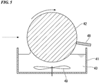
Fig. 5 is a schematic cross-sectional view of an enlarged nanocluster collection unit according to the second embodiment. -
Fig. 6 is a schematic cross-sectional view of a device for producing a nanocluster liquid dispersion according to a third embodiment. -
Fig. 7 is a mass spectrum of nanoclusters in a gas phase obtained when nanoclusters including Ta and Si as constituent elements were generated in a nanocluster generation unit. -
Fig. 8 is a high performance liquid chromatograph of a nanocluster liquid dispersion in which nanoclusters including Ta and Si as constituent elements were dispersed. -
Fig. 9 shows negative ion mass spectra of a sample obtained by performing column purification on a nanocluster liquid dispersion prepared using a method for producing a nanocluster liquid dispersion according to an aspect of the present invention,Fig. 9(a) shows the entire image of the mass spectrum, andFig. 9(b) is an enlarged view in which the peak part is enlarged. -
Fig. 10 is a high performance liquid chromatograph of a single component polystyrene. -
Fig. 11 is a high performance liquid chromatograph of a nanocluster liquid dispersion in which nanoclusters including Ti and Si as constituent elements are dispersed. -
Fig. 12 is a high performance liquid chromatograph of a nanocluster liquid dispersion in which nanoclusters including Ru and Si as constituent elements are dispersed. -
Fig. 13 is a picture of a nanocluster solid dispersion obtained when a dispersion medium of a nanocluster liquid dispersion is removed. -
Fig. 14 is a picture of a nanocluster dispersion film obtained when a dispersion medium of a nanocluster liquid dispersion is removed. - Configurations of the present invention will be described below with reference to the drawings as necessary. In the drawings used in the following description, in order to facilitate understanding of features, characteristic parts are enlarged for convenience of illustration in some cases, and dimensional ratios between components may not be the same as actual ones. The exemplified materials, dimensions, and the like are only examples, and the present invention is not limited thereto and can be appropriately changed and implemented within a range not changing the scope and spirit of the invention.
- A nanocluster liquid dispersion according to an aspect of the present invention includes nanoclusters and a dispersion medium. The nanoclusters mainly include a nanocluster with a predetermined number of atoms (cluster size). Here, "mainly" means that, when the horizontal axis represents the number of atoms in the nanocluster and the vertical axis represents the number of nanoclusters (signal strength), a peak can be observed. The number of atoms in which a peak occurs is a predetermined number of atoms. The number of peaks generated is not limited to one.
- Nanoclusters are dispersed in the dispersion medium without aggregating, and preferably uniformly dispersed.
- Here, "dispersion" means that no precipitation, which is nanocluster aggregates in a macro-perspective, is observed visually. In addition, "uniform dispersion" means that no precipitation, which is nanocluster aggregates in a macro-perspective, is observed visually, and nanoclusters are not associated with each other in a micro-perspective.
- Here, "not associated" means that, among nanoclusters in a dispersion medium immediately after dispersion, 60% or more of the nanoclusters are not associated with each other after one day. In addition, among nanoclusters in a dispersion medium immediately after dispersion, preferably, 80% or more of the nanoclusters are not associated with each other after one day and more preferably, 90% or more of the nanoclusters are not associated with each other after one day. In addition, preferably, nanoclusters are not associated with each other even after 1 week.
- Among nanoclusters in a dispersion medium immediately after dispersion, a proportion of the associated nanoclusters can be measured by the following procedure.
- First, nanoclusters are dispersed in a dispersion medium. Then, immediately after dispersion (within 1 hour), part thereof is extracted, and a particle size distribution is measured through chromatography or the like. Then, the same operation is performed after one day. The obtained particle size distribution immediately after dispersion and the obtained particle size distribution after one day are compared. At this time, in the particle size distribution after one day, when a peak occurs in part of an integer multiple of the main peak in the particle size distribution immediately after dispersion, it is said that they are associated. Since association means that nanoclusters are bonded to each other, an apparent size of nanoclusters after association is an integer multiple of nanoclusters before association.
- When it is confirmed that association has occurred, a proportion of the associated nanoclusters is calculated. First, nanoclusters with a predetermined cluster size that are most abundant in the liquid dispersion immediately after dispersion are identified. Then, an area (first area) occupied by the identified nanoclusters with a predetermined cluster size in a dispersion curve of the particle size distribution immediately after dispersion is calculated. Next, an area (second area) occupied by the identified nanoclusters with a predetermined cluster size in a dispersion curve of the particle size distribution after one day is calculated. When predetermined nanoclusters are associated with each other, the second area is smaller than the first area. A change in the area is caused by a decrease in the number of nanoclusters with a predetermined cluster size due to association. That is, when a ratio of the second area with respect to the first area is determined, a proportion of the associated nanocluster is calculated.
- Here, while details will be described below, in a nanocluster liquid dispersion according to an aspect of the present invention, in principle, a reaction of Mn+M→Mn+1···(1) through which atoms are bonded to nanoclusters is unlikely to occur and a reaction of Mn+Mn→M2n···(2) is likely to occur. In the above chemical formulae, a subscript indicates the number of constituent atoms. Formula (1) indicates that one atom is bonded to a cluster including n constituent atoms. Formula (2) indicates that a cluster including n constituent atoms and a cluster including n constituent atoms are bonded to form a cluster including 2n constituent atoms.
- When the reaction of Formula (1) is dominant, with respect to the particle size distribution immediately after dispersion, a position of the main peak in the particle size distribution after one day is significantly deviated. In this case, although it does not mean association occurs, it does not mean that nanoclusters are uniformly dispersed. Here, "significantly deviated" means that a particle size showing the main peak in the particle size distribution after one day is larger than a particle size showing the main peak in the particle size distribution immediately after dispersion by 20% or more.
- Among nanoclusters dispersed in a nanocluster liquid dispersion according to an aspect of the present invention, preferably, 5% or more of the nanoclusters have a predetermined cluster size. That is, a proportion of nanoclusters with a predetermined number of atoms with respect to all nanoclusters is preferably 5% or more.
- Among nanoclusters dispersed in a nanocluster liquid dispersion, a ratio of the predetermined nanoclusters can be calculated through liquid chromatography, thin layer chromatography, high performance liquid chromatography, X-ray small angle scattering, dynamic light scattering, electron microscopy, mass spectrometry or the like.
- When a case in which high performance liquid chromatography is performed is exemplified, a proportion of nanoclusters with a cluster size showing a representative peak selected from peaks appearing in the high performance liquid chromatograph (HPLC) of the nanocluster liquid dispersion with respect to all nanoclusters is preferably 5% or more. A higher proportion of nanoclusters with a cluster size showing the representative peak is more preferable. For example, a proportion of nanoclusters with a predetermined number of atoms with respect to all nanoclusters is preferably 10% or more, and more preferably 15% or more.
- In the field of nanoclusters, when one atom increases, properties and functions of nanoclusters change. Therefore, control of the nanocluster size using the number of atoms as a unit is extremely important. On the other hand, when nanoclusters are generated, nanoclusters with various cluster sizes are generated in many cases. This is because an energy gain according to the growth of nanoclusters is always positive and, nanoclusters grow. That is, it is extremely difficult to control the cluster size. Here, the growth of nanoclusters means that atoms are bonded to nanoclusters and a reaction of Mn+M→Mn+1···(1) occurs. A nanocluster liquid dispersion in which a cluster size is controlled with high accuracy has not been available until now.
- In addition, the fact that a proportion of nanoclusters with a predetermined cluster size among the all nanoclusters is 5% or more means that the number of nanoclusters with a predetermined cluster size is extremely large in consideration of the number of generated nanoclusters. For example, when there is 100 g of a nanocluster liquid dispersion with a concentration of 1 weight%, a weight of nanoclusters included in the liquid dispersion is 1 g, and 5% (50 mg) of them are nanoclusters with a predetermined cluster size. Since the number of atoms included in 1 mol of a material is 6.02×10²³ (Avogadro's number), the number of nanoclusters with a predetermined cluster size is about 6.02×10¹⁸ to 6.02×10¹⁹. That is, it is possible to obtain quite a large number of nanoclusters with a predetermined size from the nanocluster liquid dispersion according to an aspect of the present invention.
- On the other hand, in a nanocluster liquid dispersion of the related art, nanoclusters in which neutral atoms aggregate with each other or atomic ion and neutral atoms aggregate in a liquid dispersion are prepared. The nanocluster liquid dispersion of the related art refers to a liquid dispersion prepared by a method in which neutral atoms or atomic ions generated by a magnetron sputtering method are injected into a liquid phase. In principle, since neutral atoms aggregate to each other or atomic ions and neutral atoms aggregate in a liquid, it is extremely difficult to control in units of one atom. In this method also, it is possible to control a nanocluster size to a certain extent by examining various conditions, but it is not possible to control it to the extent of the nanocluster liquid dispersion according to an aspect of the present invention.
- A representative peak of the nanocluster can be measured through thin layer chromatography, high performance liquid chromatography, or the like. A procedure of setting a representative peak will be described below based on the example of high performance liquid chromatography.
- First, based on measurement results of HPLC, a peak having the highest intensity is set as a first representative peak. An intensity obtained by multiplying an intensity of the first representative peak by 0.9 is set as a threshold value, and when a peak has an intensity that exceeds the threshold value, the peak is set as a representative peak. That is, there may be a plurality of representative peaks.
- As will be described below, when a device for producing a nanocluster liquid dispersion according to an aspect of the present invention is used, it is possible to prepare a nanocluster liquid dispersion whose representative peak is isolated as one and a nanocluster liquid dispersion whose representative peaks are intentionally plural.
- Various nanoclusters constituting a nanocluster liquid dispersion according to an aspect of the present invention can be used. For example, nanoclusters such as a metal nanocluster consisting of a single metal element, an alloy nanocluster including a plurality of metal elements as constituent elements, and a semiconductor nanocluster including silicon as a constituent element are exemplified. As an example of the semiconductor nanocluster including silicon as a constituent element, a metal-ion-encapsulating silicon cage cluster represented by M@Si (M is a metal ion) is exemplified.
- The constituent unit of the nanocluster is preferably a transition metal element or a main group element whose ionization tendency is higher than Ag, or a complex thereof. Examples of the transition metal element whose ionization tendency is higher than Ag include Cr, Fe, Cu, and Ti, examples of the main group element include B, Al, and Si, and examples of the complex thereof include TaSi, TiSi, RuSi, and AlB.
- In the method in which neutral atoms or atomic ions generated by a magnetron sputtering method of the related art are injected into a liquid phase, neutral atoms or atomic ions are assumed to aggregate in the liquid phase. However, transition metal elements or main group elements whose ionization tendency is higher than Ag, or complexes thereof are unlikely to aggregate in the liquid phase. Thus, a nanocluster liquid dispersion in which the constituent unit of the nanocluster is a transition metal element or a main group element whose ionization tendency is higher than Ag or a complex thereof cannot be obtained in the method of the related art.
- The dispersion medium constituting the nanocluster liquid dispersion may be a solvent having low volatility or a volatile solvent. The solvent having low volatility refers to a solvent with a boiling point of 160 °C or more and a vapor pressure of 100 Pa or less at room temperature. On the other hand, the volatile solvent refers to a solvent whose boiling point is lower than the solvent having low volatility. A liquid dispersion in which nanoclusters are uniformly dispersed in a solvent having low volatility can be particularly appropriately used for applications for which volatilization of a solvent causes a problem such as a radiator. In addition, in consideration of a production process to be described below, the solvent having low volatility is preferable. On the other hand, the volatile solvent can be particularly appropriately used for applications in which a solvent is removed and a nanocluster film or the like is formed.
- The hardly volatile dispersion medium constituting the nanocluster liquid dispersion preferably has an ether bond or a siloxane bond. It is experimentally confirmed that nanoclusters do not easily aggregate in a solvent having oxygen atoms in molecules. It is thought that unshared electron pairs (also referred to as a lone pair of electrons) of oxygen in a molecular chain are coordinately bonded with nanoclusters, and are attached to the surface of nanoclusters, and aggregation between nanoclusters is inhibited. In the case of nanoclusters polarized in a liquid, for example TaSi, TiSi, RuSi or the like, an effect thereof is significant.
- More preferably, ends of the ether bond and the siloxane bond have an inert substituent terminal. Termination of the end with an inert substituent refers to termination with an alkyl group, for example, a methyl group. When the ends of the ether bond and the siloxane bond have an inert substituent terminal, it is possible to prevent molecular species used in the dispersion medium from reacting with the nanocluster. That is, it is possible to further suppress denaturation and aggregation of nanoclusters.
- On the other hand, in consideration of the use mode, a volatile dispersion medium with a lower boiling point is preferably used. If the volatile solvent is used, it is possible to avoid the residual solvent when a nanocluster film is produced.
- As the volatile dispersion medium with a low boiling point constituting the nanocluster liquid dispersion, any one selected from the group consisting of acyclic ethers, cyclic ethers, acyclic siloxanes, cyclic siloxanes, nitriles, haloalkanes, alcohols, amides, sulfoxides and benzene derivatives is preferable. It has been experimentally confirmed that, in such dispersion mediums, even if a liquid dispersion after nanoclusters are dispersed is left for a long time, the nanoclusters do not aggregate again. That is, it is possible to stably retain the form of a nanocluster liquid dispersion.
- As specific examples of the dispersion medium, examples of the acyclic ether include polyethylene glycol, polypropylene glycol, methoxy polyethylene glycol, examples of the acyclic siloxane include polydimethylsiloxane and polymethylphenylsiloxane, examples of the cyclic siloxane include hexamethylcyclotrisiloxane, and decamethylcyclohexasiloxane, examples of the cyclic ether include tetrahydrofuran, and crown ether, examples of the nitriles include acetonitrile and benzonitrile, examples of the haloalkanes include chloroform and dichloromethane, examples of the alcohols include methanol and ethanol, and examples of the benzene derivative include toluene, and dichlorobenzene.
- In the nanocluster liquid dispersion according to an aspect of the present invention, it is possible to easily transport nanoclusters with a predetermined cluster size without aggregating, and it is easy to handle when used. In addition, when the cluster size is controlled, a nanocluster film or the like prepared using a nanocluster liquid dispersion can have uniform performance.
- In the nanocluster liquid dispersion according to an aspect of the present invention, it is possible to separate nanocluster with a predetermined cluster size with a high yield using high performance liquid chromatography, a recrystallization method, or the like. In addition, since nanoclusters are dispersed in a liquid phase, it is possible to produce a nanocluster film including nanoclusters by a method of coating and the like more easily. That is, it is possible to increase applicability of nanoclusters for various applications such as catalysts, electronic devices, magnetic devices, biosensors, probes, and diagnostic agents (indicators).
- A nanocluster solid dispersion according to an aspect of the present invention mainly includes nanoclusters with a predetermined number of atoms (nanocluster size). The nanocluster solid dispersion is obtained by drying the above nanocluster liquid dispersion. In addition, the dispersion medium may be removed from the liquid dispersion using column chromatography, a recrystallization method, or the like.
Fig. 13 is a picture of the nanocluster solid dispersion obtained by drying the nanocluster liquid dispersion.Fig. 13 is a picture of the nanocluster solid dispersion represented by TaSi16 as an example. - Here, a proportion of the nanoclusters with a predetermined number of atoms with respect to all nanoclusters included in the nanocluster solid dispersion is preferably 5% or more, more preferably 10% or more, and most preferably 15% or more.
- The nanocluster solid dispersion is put into the dispersion medium to prepare a nanocluster liquid dispersion. That is, nanoclusters constituting the nanocluster solid dispersion do not aggregate with each other.
- The surface of nanoclusters constituting the nanocluster solid dispersion is covered with an organic substance. The organic substance may be a molecule constituting the dispersion medium or a protective agent that is intentionally added in a process of producing a liquid dispersion. When the surface of nanoclusters is covered with the organic substance, it is possible to prevent nanoclusters from aggregating with each other in a dried state.
- A nanocluster dispersion film according to an aspect of the present invention is formed by applying a nanocluster liquid dispersion on a substrate. The nanocluster dispersion film mainly includes nanoclusters with a predetermined number of atoms (nanocluster size). According to applications, the dispersion medium in the liquid dispersion may be removed.
Fig. 14 is a picture of a nanocluster dispersion film obtained by spin coating a nanocluster liquid dispersion. In the nanocluster dispersion film shown inFig. 14 , a nanocluster dispersion film CL with a thickness of 60 nm is formed on a Si substrate Sub. - As described above, 5% or more of nanoclusters dispersed in the nanocluster liquid dispersion with respect to all generated nanoclusters have a predetermined nanocluster size. Therefore, a proportion of nanoclusters with a predetermined nanocluster size constituting the nanocluster dispersion film with respect to all nanoclusters is 5% or more. In addition, according to high performance liquid chromatography or a recrystallization method, a liquid dispersion in which a content of nanoclusters with a predetermined cluster size increases is used, and thus it is possible to increase a proportion of nanoclusters with a predetermined nanocluster size constituting the dispersion film. A proportion of nanoclusters with a predetermined nanocluster size constituting the nanocluster dispersion film with respect to all nanoclusters is preferably 10% or more and more preferably 15% or more.
- A device for producing a nanocluster liquid dispersion includes a nanocluster generation unit and a nanocluster collection unit that is arranged in a direction in which nanoclusters generated in the nanocluster generation unit travel.
- The nanocluster generation unit generates nanoclusters in a gas phase. A generation method is not particularly limited and various methods can be used. For example, a DC discharging method, a laser evaporation method, an ion sputtering method, or a vacuum evaporation method using a Knudsen cell or the like can be used.
- As the nanocluster generation unit, a nanocluster generation device described in Patent Document 3 is preferably used. Specifically, the nanocluster generation unit preferably includes a vacuum chamber, a sputtering source, a power supply, a first inert gas supply unit, and a nanocluster growth cell. The sputtering source performs magnetron sputtering and generates a plasma. A target is provided on a cathode of the sputtering source. The power supply supplies power to the sputtering source. The first inert gas supply unit supplies a first inert gas to the sputtering source. The nanocluster growth cell is housed in the vacuum chamber. In addition, as necessary, a second inert gas introduction unit configured to introduce a second inert gas in the nanocluster growth cell may be included. In magnetron sputtering, in order to increase uniformity of generated nanoclusters, pulse discharging is preferably performed.
- In a device for producing nanocluster liquid dispersion, the nanoclusters generated in the nanocluster generation unit are collected in the nanocluster collection unit without change. When a cluster size of the nanoclusters generated in the nanocluster generation unit is uniform, the cluster size in the obtained nanocluster liquid dispersion is controlled.
- A case in which the nanocluster generation device described in Patent Document 3 which is an aspect of the nanocluster generation unit is used will be described below in detail with reference to the drawings.
-
Fig. 1 is a schematic cross-sectional view of a device for producing a nanocluster liquid dispersion according to a first embodiment. A device for producing ananocluster liquid dispersion 100 according to the first embodiment includes ananocluster generation unit 10 and ananocluster collection unit 20. - The
nanocluster generation unit 10 includes avacuum chamber 11, ananocluster growth cell 12, a sputteringsource 13, aliquid nitrogen jacket 14, acontrol device 15, apulse power supply 16, a first inertgas introduction unit 17, and a second inertgas introduction unit 18. - As the
vacuum chamber 11, a known vacuum chamber can be used. Anexhaust unit 19 is connected to thevacuum chamber 11. Theexhaust unit 19 increases a degree of vacuum in thevacuum chamber 11. As theexhaust unit 19, a turbo molecular pump or the like can be used. Theexhaust unit 19 can increase a degree of vacuum in thevacuum chamber 11 to, for example, a 10-1 to 10-4 Pa. - The
nanocluster growth cell 12 is installed in thevacuum chamber 11. The outer circumference of thenanocluster growth cell 12 is surrounded by theliquid nitrogen jacket 14. Liquid nitrogen (N2) flows in a region surrounded by the outer circumference of thenanocluster growth cell 12 and the inner circumference of theliquid nitrogen jacket 14. When liquid nitrogen flows in the region, it is possible to prevent a temperature in thenanocluster growth cell 12 from increasing and it is possible to cool helium supplied from the second inertgas introduction unit 18 to be described below. - The sputtering
source 13 includes atarget 131, ananode 132, and amagnet unit 133. The sputteringsource 13 is arranged inside thenanocluster growth cell 12 that is arranged in thevacuum chamber 11. The sputteringsource 13 is freely movable in a tube axis direction in thenanocluster growth cell 12. Thus, it is possible to freely set a stretching distance of a region in which nanoclusters grow in the tube axis direction. In other words, it is possible to freely set a length of a growth region that is a distance from the surface of thetarget 131 to ananocluster outlet 121 of thenanocluster growth cell 12. - The
target 131 functions as a cathode and is connected to thepulse power supply 16. Thepulse power supply 16 is controlled by thecontrol device 15. When power with a pulse is supplied from thepulse power supply 16 to the sputteringsource 13, a voltage is applied between thetarget 131 and theanode 132. Themagnet unit 133 applies a magnetic field to the vicinity of the surface of thetarget 131. - A material used for the
target 131 can be variously changed according to nanoclusters to be prepared. For example, in order to prepare platinum nanoclusters, platinum is used for thetarget 131, and in order to prepare TaSi nanoclusters, TaSi is used for thetarget 131. - The
control device 15 controls thepulse power supply 16. Thepulse power supply 16 applies a voltage at an on time ton and stops voltage application at an off time toff according to an on signal and an off signal from thecontrol device 15, and applies a voltage with a pulse to the sputteringsource 13. For example, as thepulse power supply 16, a modulated pulse power supply that can control power according to a duty ratio (ton/ton+toff) and a DC voltage DCV can be used. - When a duty ratio (ton/ton+toff) of the pulse signal of the
pulse power supply 16 and the like are changed, it is possible to separately form a nanocluster liquid dispersion having one representative peak and a nanocluster liquid dispersion having two or more representative peaks. - The first inert
gas introduction unit 17 is a gas flow path of which an end is arranged between thetarget 131 and theanode 132. The gas flow path can be constituted by a known pipe or the like. InFig. 1 , an inlet of the first inertgas introduction unit 17 is provided at only one place between thetarget 131 and theanode 132. The first inertgas introduction unit 17 is not limited to this configuration, and the first inertgas introduction unit 17 may be branched along the way with inlets provided at a plurality of places. A configuration in which a first inert gas can be introduced to the surface of thetarget 131 may be used. - The first inert gas may be any gas that can be used for general sputtering, and argon gas can be generally used.
- When a first inert gas is supplied from the first inert
gas introduction unit 17 to the surface of thetarget 131, strong glow discharging is generated in the vicinity of the surface of thetarget 131. When the first inert gas is ionized due to the glow discharging and collides with thetarget 131, sputtered particles are released from the target. The sputtered particles are made of neutral atoms, ions and the like derived from thetarget 131. - The second inert
gas introduction unit 18 is a gas flow path which spirally circulates inside theliquid nitrogen jacket 14 and whose end protrudes into thenanocluster growth cell 12. The gas flow path can be constituted by a known pipe or the like. The second inert gas is not particularly limited as long as it is a gas species that does not react with the generated sputtered particles. For example, helium gas or the like can be appropriately used. - The second inert
gas introduction unit 18 supplies a second inert gas that is cooled by liquid nitrogen into thenanocluster growth cell 12. The second inertgas introduction unit 18 is preferably controlled by a pressure gauge, a mass flow controller, or the like. A pressure in thenanocluster growth cell 12 can be maintained at about 10 to 40 Pa by the pressure gauge or the like. - The second inert gas introduced from the second inert
gas introduction unit 18 has a certain flow direction and the sputtered particles generated in thetarget 131 move in the flow direction. In this case, in a second inert gas atmosphere, the sputtered particles are bonded to each other and various nanoclusters are generated. - As described in Patent Document 3, the nanocluster size can be freely selected by controlling discharging power in the sputtering
source 13, a duty ratio in thepulse power supply 16, a length of a growth region in thenanocluster growth cell 12, a flow rate of the first inert gas supplied from the first inertgas introduction unit 17, a flow rate of the second inert gas supplied from the second inertgas introduction unit 18, and the like. - The
nanocluster collection unit 20 shown inFig. 1 includes astorage chamber 21 in which adispersion medium 23 can be stored, and a stirringbar 22 for flowing thedispersion medium 23 of nanoclusters. The stirringbar 22 is an aspect of a flowing unit in the scope of the claims. - The
nanocluster collection unit 20 is arranged in direction in which nanoclusters generated in thenanocluster generation unit 10 travel. While thenanocluster collection unit 20 is arranged in thevacuum chamber 11 constituting thenanocluster generation unit 10 inFig. 1 , it may be arranged in another chamber connected to the side of thevacuum chamber 11 in the direction in which nanoclusters travel. - The
nanocluster collection unit 20 collects nanoclusters in thedispersion medium 23 without aggregating. Thus, when the nanocluster size is controlled in thenanocluster generation unit 10, it is possible to isolate desired nanoclusters. - The
storage chamber 21 is a container in which thedispersion medium 23 is stored. Thestorage chamber 21 is preferably made of a material that does not serve as a gas generation source in the vacuum chamber. For example, a material such as stainless steel, glass, or the like can be used for thestorage chamber 21. - It is possible to appropriately set a capacity at which the
dispersion medium 23 of thestorage chamber 21 can be stored. When the capacity is too small, there is an increased risk of nanoclusters aggregating in thedispersion medium 23. That is, a yield of nanoclusters with a desired nanocluster size decreases. On the other hand, when the capacity is too large, it is necessary to continue sputtering for about several days to several weeks in order to obtain a liquid dispersion in which nanoclusters are dispersed at a high concentration. For example, when a time average discharging power of thepulse power supply 16 is 300 W, a flow rate of the first inert gas is 70 sccm, and a flow rate of the second inert gas is 0 sccm, an amount of thedispersion medium 23 is preferably 40 ml or more. -
Fig. 2 is a schematic cross-sectional view of a storage chamber of the device for producing a nanocluster liquid dispersion according to the first embodiment of the present invention. - The shape of the
storage chamber 21 in a plan view in the direction in which nanoclusters travel may be a circular shape or a rectangular shape. When thestorage chamber 21 is viewed in a plan view in the direction in which nanoclusters travel, a diameter r of a circle inscribed in thestorage chamber 21 is preferably 60 mm or more. The sputtered particles generated in thetarget 131 generate nanoclusters in thenanocluster growth cell 12. The generated nanoclusters are released from thenanocluster outlet 121 to thevacuum chamber 11 with a high degree of vacuum and move toward thestorage chamber 21. When the diameter of thenanocluster outlet 121 is 12 mm, and the distance between thenanocluster outlet 121 and thestorage chamber 21 is 90 mm, a spatial extent of nanoclusters on the surface of thedispersion medium 23 falls within a range of a circle with a diameter of 40 mm around a center axis of thecluster growth cell 12. Thus, when the diameter r of the circle inscribed in thestorage chamber 21 is 60 mm or more, it is possible to collect the generated nanoclusters without leakage. - When flow rates of the first and second inert gases are high, or when the length of the growth region in the
nanocluster growth cell 12 is long, a case in which a position at which nanoclusters are incident is not fallen within a range of a circle with a diameter of 40 mm can be conceivable. In this case, preferably, a position of thestorage chamber 21 in the tube axis direction is set close to thenanocluster outlet 121 so that nanoclusters can be collected without leakage, or the diameter of the circle inscribed in thestorage chamber 21 is set to be larger. - A depth d of the
storage chamber 21 is preferably 2 cm or more. The generated nanoclusters are collected in thedispersion medium 23 stored in thestorage chamber 21. A depth from a liquid surface of thedispersion medium 23 to the bottom of thestorage chamber 21 is preferably 2 cm or more although it depends on a generation rate of the nanoclusters that are incident on thedispersion medium 23 and a rotational speed of the stirringbar 22. This is because the incident nanoclusters do not reach the bottom of thestorage chamber 21 and the nanoclusters are appropriately dispersed in thedispersion medium 23. While it is possible to lower a generation rate of nanoclusters that are incident on thedispersion medium 23, a yield per unit time of nanoclusters decreases. - An
inner wall 21A in which thedispersion medium 23 of thestorage chamber 21 is stored is preferably formed of a curved surface as shown inFig. 2 . When the shape of theinner wall 21A is formed in a curved surface, it is possible to secure an area in a plan view when viewed the direction in which nanoclusters travel and prevent the capacity of thedispersion medium 23 from increasing too much. - The
storage chamber 21 preferably includes a liquid spill prevention structure that prevents thedispersion medium 23 from spilling out of thestorage chamber 21. This is because, when thedispersion medium 23 spills out of thestorage chamber 21, an amount of thedispersion medium 23 in thestorage chamber 21 decreases and there is an increased risk of aggregation. - As the liquid spill prevention structure, for example, as shown in
Fig. 3 , alid 24 having an opening may be provided in thestorage chamber 21. In order to return the dispersion medium adhered to the inner wall of thelid 24 into thestorage chamber 21, the inner wall of thelid 24 is preferably arranged inside the inner wall of thestorage chamber 21. - Since nanoclusters are incident on the
dispersion medium 23 through the opening, the diameter of the opening is preferably 40 mm or more. - The liquid spill prevention structure is not limited to this form, and, for example, an inclined surface that increases in diameter from the uppermost part of the
storage chamber 21 may be provided. In this structure, thedispersion medium 23 overflowing from thestorage chamber 21 is supplied again into thestorage chamber 21 along the inclined surface. - The
storage chamber 21 is preferably arranged so that a center position on thestorage chamber 21 and thenanocluster outlet 121 do no overlap in a plan view, and the center position of thestorage chamber 21 and thenanocluster outlet 121 are preferably separated by 20 mm or more in a plan view. - Nanoclusters generated in a
nanocluster generation device 10 are emitted in the form of a beam from thenanocluster outlet 121. On the other hand, thedispersion medium 23 stored in thestorage chamber 21 is rotated by the stirringbar 22. According to rotation by the stirringbar 22, a liquid amount of thedispersion medium 23 decreases at the central part and increases at the peripheral part of thestorage chamber 21. In addition, a flow rate of thedispersion medium 23 is higher at the peripheral part than at the center. When thestorage chamber 21 is arranged so that the center position of thestorage chamber 21 and thenanocluster outlet 121 do not overlap in a plan view, it is possible to ensure a sufficient liquid amount of a part on which nanoclusters are incident. In addition, since a flow rate of the part (peripheral part) is high, dispersibility of nanoclusters in thedispersion medium 23 is further improved. - The stirring
bar 22 rotates thedispersion medium 23 stored in thestorage chamber 21. A direction in which the stirringbar 22 rotates thedispersion medium 23 is an in-plane direction perpendicular to the direction in which nanoclusters travel. That is, thedispersion medium 23 of nanoclusters always flows in the direction in which nanoclusters travel. When thedispersion medium 23 flows, a concentration of nanoclusters on the surface on which nanoclusters are incident is prevented from being extremely higher. As a result, aggregation of nanoclusters on the incidence surface of thedispersion medium 23 and inside thedispersion medium 23 is avoided. - The rotational speed of the stirring
bar 22 is set as a rotational speed at which nanoclusters do not aggregate in thedispersion medium 23. The rotational speed at which nanoclusters do not aggregate differs according to a volume of thestorage chamber 21, a type of a solution of thedispersion medium 23, a generation rate of nanoclusters that are incident, and the like, and an appropriate rotational speed can be confirmed by a prior examination. When it is described that nanoclusters do not aggregate, this means that a cluster size of a representative peak of nanoclusters collected in thedispersion medium 23 is not larger than a cluster size of a representative peak of nanoclusters in a gas phase state prepared in thenanocluster generation unit 10 by 10% or more. Determination of whether nanoclusters have aggregated with each other can be confirmed according to whether precipitation has occurred in thedispersion medium 23. - For example, when the
storage chamber 21 has a cylindrical shape with a diameter of 90 mm, the stirringbar 22 has a size of 8 mm in diameter and 40 mm in length, and thedispersion medium 23 is polyethylene glycol, the rotational speed of the stirringbar 22 is preferably 400 rpm or more and 1000 rpm or less. In this case, when the rotational speed of the stirringbar 22 is less than 400 rpm, aggregation of nanoclusters proceeds and precipitation in thedispersion medium 23 is confirmed. On the other hand, when the rotational speed exceeds 1000 rpm, rotation becomes faster and there is an increased risk of a liquid spilling out. - As the
dispersion medium 23 stored in thestorage chamber 21, dispersion mediums constituting the above nanocluster liquid dispersion can be used. Among them, a dispersion medium is preferably a solvent having low volatility with a boiling point of 160 °C or more and a vapor pressure of 100 Pa or less at room temperature. Thedispersion medium 23 is stored in thestorage chamber 21 provided in thevacuum chamber 11. When a boiling point of thedispersion medium 23 is low, an amount of thedispersion medium 23 decreases with the passages of time, and there is an increased risk of nanoclusters aggregating thedispersion medium 23. - A
detection unit 30 configured to detect nanoclusters may be provided between thenanocluster generation unit 10 and thenanocluster collection unit 20. Thedetection unit 30 is a probe plate that is retractable in the vertical direction with respect to the direction in which nanoclusters travel. - When the
detection unit 30 as a probe plate is inserted between thenanocluster outlet 121 of thenanocluster generation unit 10 and thestorage chamber 21 of thenanocluster collection unit 20, nanoclusters emitted from thenanocluster outlet 121 collide on the probe plate. For example, when Ta and Si are used as elements constituting nanoclusters, if nanoclusters are appropriately generated, the probe plate is colored. On the other hand, if nanoclusters are not appropriately generated, a transparent film is formed on the surface of the probe plate. - The
detection unit 30 confirms whether desired nanoclusters have been generated. When it is confirmed using thedetection unit 30 that desired nanoclusters are generated in thenanocluster generation unit 10, it is possible to increase a concentration of nanoclusters with a desired cluster size in the obtained nanocluster liquid dispersion. - In the device for producing a
nanocluster liquid dispersion 100 according to the first embodiment, the nanocluster size can be controlled by thenanocluster generation unit 10 and the nanoclusters can be dispersed without aggregating by thenanocluster collection unit 20. That is, it is possible to isolate nanoclusters with a desired cluster size. -
Fig. 4 is a schematic cross-sectional view of a device for producing a nanocluster liquid dispersion according to a second embodiment. A difference between a device for producing ananocluster liquid dispersion 200 according to the second embodiment and the device for producing ananocluster liquid dispersion 100 according to the first embodiment is ananocluster collection unit 40. Description of the same parts as in the first embodiment will be omitted below. - The configuration of the
nanocluster generation unit 10 is the same as that in the first embodiment. The only difference is that thenanocluster generation unit 10 is of a vertical type in the first embodiment and is of a horizontal type in the second embodiment. Thenanocluster generation unit 10 may also be of a vertical type in the second embodiment. - The
nanocluster collection unit 40 in the device for producing ananocluster liquid dispersion 200 according to the second embodiment includes astorage chamber 41 and arotating body 42. InFig. 4 , adispersion medium 43 is stored in thestorage chamber 41. Thevacuum chamber 11 constituting thenanocluster generation unit 10 and avacuum chamber 44 constituting thenanocluster collection unit 40 are shown as separate members inFig. 4 , but they may be one large chamber. Anexhaust device 47 for increasing a degree of vacuum of the inside is connected to thevacuum chamber 44. As theexhaust device 47, a turbo molecular pump or the like can be used. Theexhaust device 47 can increase a degree of vacuum in thevacuum chamber 44 to, for example, 10-2 to 10-6 Pa. - The size, shape, and the like of the
storage chamber 41 can be the same as those in thestorage chamber 21 of the first embodiment. As shown inFig. 4 , a configuration in which a flow path is provided below thestorage chamber 41, and thedispersion medium 43 stored in thestorage chamber 41 can be easily discharged by opening apetcock 45 may be used. The same dispersion medium as in the first embodiment can be used as a dispersion medium stored. - The rotating
body 42 is a rotating body having an axis of rotation in a direction perpendicular to the direction in which nanoclusters travel. The rotatingbody 42 is an aspect of a flowing unit in the scope of the claims. The rotatingbody 42 is supported by asupport 46 and is disposed so that a part thereof is immersed in the dispersion medium stored in thestorage chamber 41. InFig. 4 , thesupport 46 supports the rotating body from above, but it is not limited to this form. Thesupport 46 may support the rotatingbody 42 from below or side. In consideration of maintenance, thesupport 46 preferably supports therotating body 42 from below. Preferably, the rotatingbody 42 and thesupport 46 are freely attachable. This is because it is preferable to replace therotating body 42 for each type of the dispersion medium used and for each type of the nanocluster. -
Fig. 5 is a schematic cross-sectional view in which a part of thenanocluster collection unit 40 according to the second embodiment is enlarged. As shown inFig. 5 , when therotating body 42 rotates, thedispersion medium 43 stored in thestorage chamber 41 is pulled up. The pulled-updispersion medium 43 follows the surface of therotating body 42 according to the rotation of therotating body 42. - Nanoclusters emitted from the
nanocluster outlet 121 of thenanocluster generation unit 10 are incident on a side surface of therotating body 42. A liquid dispersion with a high nanocluster concentration on the surface on which one nanocluster is incident the rotatingbody 42 is transported in the rotation direction. Thus, when the next nanocluster is incident, it is possible to lower a nanocluster concentration on the incidence surface. That is, a nanocluster concentration on the surface on which nanocluster are incident is prevented from being extremely higher. When a nanocluster concentration is prevented from being extremely higher at a part, aggregation of nanoclusters on the incidence surface of thedispersion medium 43 and inside thedispersion medium 43 is avoided. - The rotational speed of the
rotating body 42 is set as a rotational speed at which nanoclusters do not aggregate in thedispersion medium 43. A higher rotational speed of therotating body 42 is preferable. - The rotational speed at which nanoclusters do not aggregate differs according to a volume of the
storage chamber 41, an amount of thedispersion medium 43 pulled-up on the surface of therotating body 42, a type of a solution of thedispersion medium 43, a speed of nanoclusters that are incident, and the like. An appropriate level of the rotational speed can be confirmed by a prior examination. When the rotational speed is higher, it is possible to increase an amount of thedispersion medium 43 pulled-up on the surface of therotating body 42. When the liquid dispersion is efficiently transported in the rotation direction, it is possible to prevent the occurrence of a part in which a nanocluster concentration is high locally. - Diamond-like carbon is preferably applied to the surface of the
rotating body 42. When diamond-like carbon is applied, it is possible to increase wettability of thedispersion medium 43 and it is possible to increase an amount of thedispersion medium 43 pulled-up on the surface of therotating body 42. - The interior of the
rotating body 42 preferably has a hollow structure. When the interior of therotating body 42 has a hollow structure, it is possible to reduce a weight of therotating body 42 and increase a rotational speed. - A position at which the
rotating body 42 is disposed is preferably within 350 mm from thenanocluster outlet 121. When the position is too far from thenanocluster outlet 121, nanoclusters diffuse and do not collide on the surface of therotating body 42 appropriately. - A
squeegee 48 is preferably provided behind the rotatingbody 42 in the rotation direction. Thesqueegee 48 may be supported by thesupport 46 or may be connected to another part and supported. Thesqueegee 48 is substantially in close contact with the rotatingbody 42 and it is preferable to control a distance to therotating body 42 with an accuracy of 0.1 mm or less. - The
squeegee 48 removes a part of thedispersion medium 43 applied to the surface of therotating body 42. Thedispersion medium 43 is a liquid dispersion after nanoclusters are dispersed. When thesqueegee 48 is provided, it is possible to separate thedispersion medium 43 pulled-up on therotating body 42 and the liquid dispersion after nanoclusters are dispersed. A liquid dispersion separated by providing a guide plate or the like may be prevented from being mixed into inside thestorage chamber 41. - Preferably, in the
storage chamber 41, a stirringunit 49 configured to stir thedispersion medium 43 stored in thestorage chamber 41 may be provided. As shown inFig. 5 , the stirringunit 49 may be a stirring blade provided below the rotatingbody 42, a stirring bar, or the like. When the storeddispersion medium 43 is stirred by the stirringunit 49, it is possible to obtain a uniform concentration of nanoclusters dispersed in thedispersion medium 43. - In the device for producing a
nanocluster liquid dispersion 200 according to the second embodiment, the detection unit may also be provided. - In the device for producing a
nanocluster liquid dispersion 200 according to the second embodiment, the nanocluster size can be controlled by thenanocluster generation unit 10. In addition, according to therotating body 42 of thenanocluster collection unit 40, thedispersion medium 43 on the surface on which nanoclusters are incident can flow about at a speed at which nanoclusters do not aggregate on the surface of thedispersion medium 43. Accordingly, it is possible to prepare a nanocluster liquid dispersion on which nanoclusters are incident thedispersion medium 43 do not aggregate, but they are uniformly dispersed. That is, it is possible to isolate nanoclusters with a desired cluster size. -
Fig. 6 is a schematic cross-sectional view of a device for producing a nanocluster liquid dispersion according to a third embodiment. A difference between a device for producing ananocluster liquid dispersion 300 according to the third embodiment and the device for producing ananocluster liquid dispersion 100 according to the first embodiment is ananocluster collection unit 50. Description of the same parts as in the first embodiment will be omitted below. - The
nanocluster generation unit 10 in the third embodiment is of a horizontal type as in the second embodiment. - The
nanocluster collection unit 50 includes asubstrate 51, acooling mechanism 52, a dispersionmedium supply unit 53, and acollection container 54. InFig. 6 , thevacuum chamber 11 constituting thenanocluster generation unit 10 and avacuum chamber 56 constituting thenanocluster collection unit 50 are shown as separate members, but they may be one large chamber. Theexhaust device 57 for increasing a degree of vacuum in the inside is connected to thevacuum chamber 56. As theexhaust device 57, a turbo molecular pump or the like can be used. Theexhaust device 57 can increase a degree of vacuum in thevacuum chamber 56 to, for example, 10-2 to 10-6 Pa. - The
substrate 51 is arranged to cross the direction in which nanoclusters travel. The material of thesubstrate 51 is preferably a material with favorable conductivity, and oxygen-free copper or the like can be used. - A dispersion medium is sprayed onto the
substrate 51 from the dispersionmedium supply unit 53. As the dispersion medium, a highly volatile solvent can also be used in addition to the same dispersion medium as in the first embodiment. For example, tetrahydrofuran can be used. In the third embodiment, since the dispersion medium is not stored, but it is sprayed, a solvent that is more volatile than the dispersion mediums of the first embodiment and the second embodiment can be used. - One end of the dispersion
medium supply unit 53 is connected to an external tank in which a dispersion medium is stored and the other end thereof is provided in the vicinity of thesubstrate 51. When the dispersion medium supplied from the dispersionmedium supply unit 53 is sprayed onto thesubstrate 51, it is cooled by thecooling mechanism 52 and becomes a solid. At this time, nanoclusters and the dispersion medium are co-deposited, and the nanoclusters are dispersed in a solvent matrix. Then, when the solvent matrix is dissolved, a liquid dispersion is obtained. As thecooling mechanism 52, a known cold trap or the like can be used. - The nanocluster and the dispersion medium that are co-deposited on the surface of the
substrate 51 become a nanocluster liquid dispersion when thesubstrate 51 is heated. The nanocluster liquid dispersion flows on the surface of thesubstrate 51 and is added dropwise to thecollection container 54. A configuration in which a flow path is provided below thecollection container 54 and the liquid dispersion collected in thecollection container 54 can be easily discharged by opening apetcock 55 may be used. - In the device for producing a
nanocluster liquid dispersion 300 according to the third embodiment, a nanocluster liquid dispersion is prepared by spraying the dispersion medium onto the surface of thesubstrate 51 on which nanoclusters are incident by the dispersionmedium supply unit 53. Therefore, whenever nanoclusters are incident on thesubstrate 51, a new dispersion medium is supplied by spraying. Therefore, it is possible to prevent a cluster concentration in the liquid dispersion from increasing. Accordingly, it is possible to prepare a nanocluster liquid dispersion in which nanoclusters do not aggregate, but they are uniformly dispersed. - In the device for producing a
nanocluster liquid dispersion 300 according to the third embodiment, when the nanocluster size generated in thenanocluster generation unit 10 is controlled, it is possible to isolate nanoclusters with a desired cluster size. - A method for producing a nanocluster liquid dispersion according to the present embodiment includes a nanocluster generation process in which nanoclusters are generated and a nanocluster collection process in which nanoclusters are collected in a dispersion medium while flowing on an incidence surface of the dispersion medium on which the generated nanoclusters are incident.
- The nanocluster generation process is not particularly limited. The nanocluster generation process can be appropriately set according to a type and a cluster size of nanoclusters dispersed in the nanocluster liquid dispersion.
- On the other hand, in the nanocluster generation process, it is preferable to control the cluster size. This is because the nanoclusters generated in the nanocluster generation process are collected in the nanocluster collection process. The nanocluster generation process in which the cluster size is controlled refers to a process in which a nanocluster with a cluster size showing a representative peak selected from a peak of a mass spectrum of the nanocluster generated in a gas phase is generated. A proportion of nanoclusters with a predetermined cluster size (showing a representative peak) with respect to all of the generated nanoclusters is preferably 5% or more.
- Specifically, in the nanocluster generation process, the nanocluster generation device described in Patent Document 3 and the nanocluster generation unit in the above device for producing a nanocluster liquid dispersion can be used. The cluster size of the nanoclusters generated in the nanocluster generation process is controlled with an extremely high accuracy in a gas phase state. In the nanocluster generation process, when nanoclusters with a desired cluster size are generated in advance, the cluster size of the nanoclusters collected in a liquid dispersion collection process to be described below can be constant.
- A type of the nanocluster generated in the nanocluster generation process is not particularly limited. Elements constituting the nanocluster may aggregate in a gas phase. Examples of the generated nanocluster include a metal nanocluster including a single metal element as a constituent element, an alloy nanocluster including a plurality of metal elements as constituent elements, and a semiconductor nanocluster including silicon as a constituent element. A nanocluster of Pt, Au, Ag, Cu, Cr, Ti, or Fe can be generated as the metal nanocluster, a nanocluster of CoPt, FePt, or the like can be generated as the alloy nanocluster, and Si, TaSi, TiSi, LuSi, RuSi, WSi, and MoSi can be generated as the semiconductor nanocluster.
- Preferably, a nanocluster detection process is performed between the nanocluster generation process and the nanocluster collection process. In the nanocluster detection process, it is checked whether predetermined nanoclusters have been formed. As a result, it is possible to confirm that nanoclusters with a predetermined cluster size are included in the liquid dispersion and it is possible to increase a concentration of predetermined nanoclusters in the prepared nanocluster liquid dispersion.
- In the nanocluster collection process, the dispersion medium on which nanoclusters are incident flows. This is because the nanoclusters generated in the nanocluster generation process are collected without aggregating.
- For example, as in the
above detection unit 30, when a probe plate is installed in the direction in which nanoclusters travel, the probe plate is colored in about several seconds. That is, nanoclusters are incident on the dispersion medium with a high frequency. Thus, when the dispersion medium does not flow, the nanoclusters that are incident on the dispersion medium aggregate with each other on the liquid surface or in the liquid. When the dispersion medium on which nanoclusters are incident flows, it is possible to prevent a nanocluster concentration from locally increasing on the surface of the dispersion medium and in the dispersion medium, and it is possible to increase dispersibility of the nanoclusters. - In the nanocluster collection process, on the surface of the liquid dispersion, nanoclusters are most likely to aggregate with each other. This is because, when nanoclusters are incident on the liquid surface, they receive resistance, and a speed of the nanoclusters temporarily decreases on the surface of the liquid dispersion.
- Thus, in the nanocluster collection process, preferably, the dispersion medium flows so that a density of nanoclusters on the surface of the dispersion medium is equal to or less than an aggregation limit.
- The aggregation limit refers to a density at which nanoclusters do not come in contact with each other on the surface of the dispersion medium. For example, if the nanocluster has a size of 1 nm in diameter, when there are 1014 nanoclusters or more in 1 cm2, the nanoclusters come in contact with each other. Although the nanoclusters contacting with each other do not immediately aggregate, a density of nanoclusters on the surface of the dispersion medium is preferably 1014 nanoclusters/cm2 or less for the nanocluster having a size of 1 nm in diameter,.
- The density of nanoclusters on the surface of the dispersion medium is greatly influenced also by a nanocluster incident flux. The incident flux refers to the number of particles of nanocluster that are incident in 1 cm2 per second. When the incident flux is high, it is preferable to increase a flow velocity. When the incident flux is low, it is not as necessary to accelerate a stirring speed. In both cases, the dispersion medium flows so that the density of nanoclusters on the surface of the dispersion medium is an aggregation limit or less, and thus it is possible to further suppress aggregation of nanoclusters.
- More specifically, for example, in order to collect 10 mg nanoclusters per hour, nanoclusters are incident on the liquid dispersion at 6 nmol (=3.3×10¹⁵ nanoclusters)/sec in an area of 12 cm2 (calculated area of nanoclusters on the incidence surface at a diameter of 40 mm). An incident amount when the dispersion medium is fixed, 2.8×10¹⁴ nanoclusters/sec·cm2 is obtained. In this case, when a flow velocity is 10 cm/sec or more, the density of nanoclusters on the surface of the dispersion medium can be to 1014 nanoclusters/cm2 or less. In consideration of a limit value of the current nanocluster incident flux, a surface speed of the nanocluster liquid dispersion is preferably 20 cm/sec or more and more preferably 100 cm/sec or more.
- A method of flowing the dispersion medium on which nanoclusters are incident is not particularly limited. For example, the stirring bar, the rotating body, or the like described in the device for producing a nanocluster liquid dispersion can be used.
- As described in the device for producing a nanocluster liquid dispersion, in principle, since the nanocluster liquid dispersion is prepared in the vacuum chamber, a solvent having low volatility with a high boiling point is preferably used. On the other hand, in consideration of the use mode, when a solvent having low volatility is used, the residual solvent is conceivable. Thus, the dispersion medium of the nanocluster liquid dispersion is preferably a volatile solvent.
- Thus, a replacement process in which a dispersion medium is replaced with a volatile solvent having a lower boiling point than the dispersion medium used during collection may be additionally included after the nanocluster collection process. For replacement of the dispersion medium, first, only nanoclusters are extracted from the liquid dispersion according to, for example, column chromatography or a recrystallization method. Then, when the extracted nanoclusters are added to the volatile solvent again while stirring, a liquid dispersion in which nanoclusters are dispersed in the volatile solvent is obtained. When the replacement process is performed in the presence of oxygen or water, there is a risk of nanoclusters aggregating. The replacement process is preferably performed under oxygen-free and anhydrous conditions using a glove box or the like. The solvent used for replacement is preferably subjected to a degassing and dehydration treatment.
- When such a liquid dispersion is used, it is possible to easily apply the nanocluster liquid dispersion to the substrate. For coating, a spray coating method, a dispenser coating method, a spin coating method, a knife coating method, an inkjet coating method, a screen printing method, an offset printing method, or a die coating method can be used. When the solvent is removed from the applied liquid dispersion, a nanocluster dispersion film is easily obtained. A proportion of nanoclusters with a predetermined nanocluster size constituting the obtained nanocluster dispersion film with respect to all nanoclusters is 5% or more.
- Here, the substrate is not particularly limited, and a conductive substrate, a non-conductive substrate, and the like are appropriately selected according to applications. Examples of the conductive substrate include a metal such as gold, silver, and aluminum, a metal oxide such as indium tin oxide (ITO), fluorine-doped tin oxide (FTO), and sapphire, and an organic conductor such as graphite and carbon nanotubes. In addition, examples of the non-conductive substrate include glass, a ceramic, and a resin. In addition, examples of the semiconductors include a semiconductor of Si, GaAs, and the like.
- When the method for producing a nanocluster liquid dispersion according to the present embodiment is used, a nanocluster liquid dispersion in which nanoclusters are uniformly dispersed is obtained. In addition, in the nanocluster generation process, when the nanocluster size is controlled in advance, it is possible to isolate nanoclusters with a desired cluster size.
- Hereinafter, effects of the present invention will become more apparent from examples. The present invention is not limited to the following examples, but can be appropriately changed and implemented within ranges in which the scope and spirit of the invention are not changed.
- First, nanocluster including Ta and Si as constituent elements in a gas phase were generated using the nanocluster generation unit described in the first embodiment.
-
Fig. 7 is a mass spectrum of nanoclusters generated in a gas phase. The nanoclusters generated in the gas phase were confirmed as TaSi16 + from the mass spectrum. - Next, the nanoclusters generated in a gas phase were incident on the dispersion medium stored in the storage chamber to obtain a nanocluster liquid dispersion. As the dispersion medium, a polyethylene glycol dimethyl ether (PEG, molecular weight of about 250 u, boiling point 250 °C or more) having a methyl group as an inert substituent terminal was used. The dispersion medium was stirred by the stirring bar.
-
Fig. 8 is a high performance liquid chromatograph (HPLC) of a nanocluster liquid dispersion of TaSi. The horizontal axis represents an amount of a solution supplied to a column and the vertical axis represents an absorbance. As the dispersion medium, a polyethylene glycol dimethyl ether (PEG, molecular weight of about 250 u, boiling point 250 °C or more) whose end was terminated with an inert methyl group was used and TaSin -, TaSin +, and TaSin (0) were generated as nanoclusters. - In the HPLC, while a solution was supplied from one side of an analysis column, an absorbance was measured using a spectrophotometer installed at the other side of the column. A size exclusion column was used for analysis. The analysis column had a porous structure therein, and a traveling speed in the analysis column differed according to the nanocluster size. Since nanoclusters with a small size traveled past the interior of the porous structure in the traveling direction, they had a lower traveling speed than nanoclusters with a large size. Therefore, nanoclusters with a relatively large size (large mass) were confirmed in a stage in which a volume of supplied solution into the analysis column was small. Subsequently, the nanocluster size decreased (small mass) as a volume of the solution supplied increased.
- That is, the HPLC spectrum shown in
Fig. 8 shows an abundance ratio of all nanoclusters included in the liquid dispersion. The horizontal axis represents an elution volume, that is, a cluster size, and the vertical axis represents an absorbance, that is, an abundance of clusters. Based on the graph, it was confirmed that there was a maximum peak at 8.5 mL (supply rate of a solvent at 0.5 mL/min, 17 minutes after the solvent was supplied) in the horizontal axis. - Next, a mass spectrum of a fraction component with respect to the representative peak of the nanocluster liquid dispersion was confirmed.
Fig. 9 shows negative ion mass spectra of a sample obtained by performing column purification on a nanocluster liquid dispersion prepared using the method for producing a nanocluster liquid dispersion according to an aspect of the present invention,Fig. 9(a) shows the entire image of the mass spectrum, andFig. 9(b) is an enlarged view in which the peak part is enlarged. The mass spectrum inFigs. 9(a) and 9(b) was measured using the sample at a part of 8.5 mL inFig. 8 . The horizontal axis represents an m/z value obtained by dividing a mass number by a charge and the vertical axis represents a detection intensity. - As shown in
Figs. 9(a) and 9(b) , based on the result of mass analysis, it was found that TaSi13 -(m/z≅545u), TaSi14 -(m/z≅574u), TaSi15 -(m/z≅602u), and TaSi16 - (m/z≅630u) were generated. These were assumed as fragmented products of TaSi16 +. That is, a nanocluster showing the representative peak was TaSi16 + and it showed that TaSi16 + was included in the liquid dispersion as a main component. On the other hand, Sin - with different sizes and different compositions were not observed. That is, inFig. 7 andFigs. 9(a) and 9(b) , it was confirmed that nanoclusters in a gas phase were dispersed in the dispersion medium without aggregating. - Next, a proportion of the confirmed nanoclusters with a predetermined cluster size (TaSi16 +) with respect to all nanoclusters was calculated. The calculation was performed according to the following procedure.
- First, the HPLC result obtained when a material of a single component (molecular weight was determined in one operation) was measured was confirmed.
Fig. 10 is an HPLC of a single component polystyrene. A half width of a peak obtained in this case was 0.63 mL and a peak value was 8.28 mL. The polystyrene having the same molecular weight was used as a reference material, and was detected as a peak curve with a certain width in the chromatogram. - That is, in the HPLC of the nanocluster liquid dispersion of TaSi shown in
Fig. 8 , a single TaSi16 is detected as a peak curve with a certain width. Thus, the HPLC shown inFig. 8 was fitted to a peak curve with a half width of 0.63 mL around a top point of the peak. A dotted line inFig. 8 shows a fitting result. In other words, in the HPLC of the nanocluster liquid dispersion of TaSi, a dotted line part shows a peak generated due to TaSi16. Thus, an area proportion of the dotted line part with respect to the area of the solid line part can be converted into a proportion of the confirmed nanoclusters with a predetermined cluster size (TaSi16 +) with respect to all nanoclusters. - As the result obtained by conversion in the above procedure, a proportion of the confirmed nanoclusters with a predetermined cluster size (TaSi16 +) with respect to all nanoclusters was 57.2%.
- As described above, a nanocluster liquid dispersion in which nanoclusters including TaSi as a constituent element were dispersed was obtained. In addition, the obtained nanocluster liquid dispersion was stable and precipitation of nanoclusters was not observed after the liquid dispersion was left for about 6 months. That is, it was found that nanoclusters with a predetermined size were uniformly dispersed in the nanocluster liquid dispersion.
- The PEG liquid dispersion of the TaSi nanoclusters prepared in Example 1 was recrystallized using a hexane/acetonitrile mixture solvent and the TaSi nanoclusters were separated from the dispersion medium. The separated TaSi nanoclusters were dispersed in tetrahydrofuran, and toluene again. In both cases, the TaSi nanoclusters after re-dispersion were not precipitated, but they were stably dispersed. It was confirmed that the dispersion medium could be replaced with a volatile organic solvent with a high volatility from a PEG with a low volatility. In addition, the liquid dispersion after replacement was stable and precipitation of the nanoclusters was not observed.
- Example 3 was the same as Example 1 except that elements constituting nanoclusters generated in a gas phase in the nanocluster generation unit were Ti and Si. The obtained nanocluster was TiSin.
-
Fig. 11 is an HPLC of a nanocluster liquid dispersion of TiSi prepared using the method for producing a nanocluster liquid dispersion according to an aspect of the present invention. The solid line shows HPLC results of all nanoclusters, and the dotted line shows a distribution of nanoclusters with a cluster size in the process confirmed through fitting. - In the same procedure as in Example 1, a calculated proportion of nanoclusters with a predetermined cluster size with respect to all nanoclusters was 40.2%. In addition, the obtained nanocluster liquid dispersion was stable and precipitation of nanoclusters was not observed after the liquid dispersion was left for about 6 months.
- The PEG liquid dispersion of the TiSi nanoclusters prepared in Example 3 was recrystallized using a hexane/acetonitrile mixture solvent. Then, the TiSi nanoclusters were separated from the dispersion medium. The TiSi nanocluster sample separated from the dispersion medium included Si at 15 weight% or more and Ti at 1 weight% or more, and the remaining component that was polyethylene glycol dimethyl ether bonded to the nanocluster. The TiSi nanoclusters separated from the dispersion medium were dispersed in tetrahydrofuran again. The TiSi nanoclusters after re-dispersion were not precipitated and were stably dispersed. It was confirmed that the dispersion medium could be replaced with a volatile organic solvent with a high volatility from a PEG with a low volatility. In addition, the liquid dispersion after replacement was stable and precipitation of the nanoclusters was not observed.
- Example 5 was the same as Example 1 except that elements constituting nanoclusters generated in a gas phase in the nanocluster generation unit were Ru and Si. The obtained nanocluster was RuSin +.
-
Fig. 12 is an HPLC of a nanocluster liquid dispersion of RuSi prepared using the method for producing a nanocluster liquid dispersion according to an aspect of the present invention. The solid line shows HPLC results of all nanoclusters, and the dotted line shows a distribution of nanoclusters with a cluster size in the process confirmed through fitting. - In the same procedure as in Example 1, a calculated proportion of nanoclusters with a predetermined cluster size with respect to all nanoclusters was 42.1%. In addition, the obtained nanocluster liquid dispersion was stable and precipitation of nanoclusters was not observed after the liquid dispersion was left for about 3 months.
- TaSi and TiSi nanocluster liquid dispersions that were dispersed in tetrahydrofuran again, which were obtained in Example 2 and Example 4, were applied to a glass substrate and a Si substrate. More specifically, a solution of 10 mg/mL was applied to a Si substrate with an oxide film (111) using a spin coater (device: model number SC2005 commercially available from Aiden) at a rotational speed of 3000 rpm. The coated sample was dried by air to prepare a TaSi nanocluster dispersion film.
Fig. 14 is a cross-sectional view of the nanocluster dispersion film. - TiSi nanocluster liquid dispersions were prepared in the same method as in Example 4 except that, as a hardly volatile dispersion medium used when a nanocluster liquid dispersion was prepared, a dimethyl silicone oil (Example 7,
viscosity 200 mm2/s), a dimethyl silicone oil (Example 8,viscosity 1000 mm2/s) and a methylphenyl silicone oil (Example 9, viscosity 160 mm2/s) were used in place of the polyethylene glycol dimethyl ether. In addition, the obtained nanocluster liquid dispersion was stable and precipitation of nanoclusters was not observed after the liquid dispersion was left for about 6 months. Precipitation of the nanoclusters was visually evaluated. - An ionic liquid was used as a hardly volatile dispersion medium used when a nanocluster liquid dispersion was prepared. As the ionic liquid, 1-butyl-3-methylimidazolium hexafluorophosphate was used in Example 11 and 1-butyl-1-methylpyrrolidinium bis(trifluoromethanesulfonyl)imide was used in Example 12. When the TiSi nanocluster liquid dispersion was prepared using such an ionic liquid and left for 1 week, slight association between the nanoclusters was observed. Compared to the nanocluster liquid dispersions prepared in Examples 1 to 5 and 8 to 10, dispersibility was not favorable.
- A TiSi nanocluster liquid dispersion was prepared using a liquid paraffin as a hardly volatile dispersion medium used when a nanocluster liquid dispersion was prepared. When the prepared nanocluster liquid dispersion was left for 1 week, slight association between the nanoclusters was observed. Compared to the nanocluster liquid dispersions prepared in Examples 1 to 5 and 8 to 10, dispersibility was not favorable.
-
- 100 Device for producing nanocluster liquid dispersion
- 10 Nanocluster generation unit
- 11, 44, 56 Vacuum chambers
- 12 Nanocluster growth cell
- 13 Sputtering source
- 14 Liquid nitrogen jacket
- 15 Control device
- 16 Pulse power supply
- 17 First inert gas introduction unit
- 18 Second inert gas introduction unit
- 19, 47, 57 Exhaust device
- 20, 40, 50 Nanocluster collection unit
- 21, 41 Storage chamber
- 22 Stirring bar
- 23, 43 Dispersion medium
- 30 Detection unit
- 42 Rotating body
- 45, 55 Petcock
- 46 Support
- 48 Squeegee
- 49 Stirring unit
- 51 Substrate
- 52 Cooling unit
- 53 Dispersion medium supply unit
- 54 Collection container
Claims (25)
- A nanocluster liquid dispersion in which nanoclusters with a predetermined number of atoms are dispersed.
- The nanocluster liquid dispersion according to claim 1,
wherein the nanoclusters with a predetermined number of atoms are uniformly dispersed. - The nanocluster liquid dispersion according to claim 1 or 2,
wherein a dispersion medium in which nanoclusters are dispersed is a solvent having low volatility. - The nanocluster liquid dispersion according to claim 3,
wherein the dispersion medium has an ether bond or a siloxane bond. - The nanocluster liquid dispersion according to claim 4,
wherein an end of the ether bond or the siloxane bond has an inert substituent terminal. - The nanocluster liquid dispersion according to claim 1 or 2,
wherein a dispersion medium in which nanoclusters are dispersed is a volatile solvent. - The nanocluster liquid dispersion according to claim 6,
wherein the dispersion medium is any one selected from the group consisting of a acyclic ether, a cyclic ether, a acyclic siloxane, nitriles, haloalkanes, alcohols, amides, sulfoxides, and benzene derivatives. - The nanocluster liquid dispersion according to any one of claims 1 to 7,
wherein a constituent unit of the nanocluster is a metal element or a main group element whose ionization tendency is higher than Ag, or a complex thereof. - The nanocluster liquid dispersion according to any one of claims 1 to 8,
wherein the nanocluster is a metal-ion-encapsulating silicon cage cluster represented by M@Si. - The nanocluster liquid dispersion according to any one of claims 1 to 9,
wherein the nanocluster is any one selected from the group consisting of a complex cluster of Ta and Si, a complex cluster of Ti and Si, a complex cluster of Lu and Si, a complex cluster of Mo and Si, a complex cluster of W and Si, and a complex cluster of Ru and Si. - The nanocluster liquid dispersion according to any one of claims 1 to 10,
wherein a proportion of the nanoclusters with a predetermined number of atoms with respect to nanoclusters included in the nanocluster liquid dispersion is 5% or more. - A nanocluster solid dispersion comprising nanoclusters with a predetermined number of atoms.
- A nanocluster dispersion film comprising nanoclusters with a predetermined number of atoms
- A method for producing a nanocluster liquid dispersion, the method comprising:generating nanoclusters; andcollecting the nanoclusters in a dispersion medium while flowing the dispersion medium where the generated nanoclusters are incident.
- The method for producing a nanocluster liquid dispersion according to claim 14,
wherein, the dispersion medium flows so that a density of nanoclusters on the surface of the dispersion medium does not exceed an aggregation limit, in the collecting. - The method for producing a nanocluster liquid dispersion according to claim 14 or 15,
wherein the dispersion medium is a solvent having low volatility with a boiling point of 160 °C or more and a vapor pressure of 100 Pa or less at room temperature. - The method for producing a nanocluster liquid dispersion according to any one of claims 14 to 16, further comprising after the collecting:
replacing the dispersion medium with a volatile dispersion medium having a lower boiling point than the dispersion medium. - The method for producing a nanocluster liquid dispersion according to any one of claims 14 to 17, further comprising between the generating and the collecting:
detecting whether predetermined nanoclusters are generated in the generating. - A device for producing a nanocluster liquid dispersion comprising:a nanocluster generation unit; anda nanocluster collection unit that is arranged in a traveling direction of nanoclusters which is generated in the nanocluster generation unit.
- The device for producing a nanocluster liquid dispersion according to claim 19,
wherein the nanocluster generation unit includes:a vacuum chamber;a sputtering source which includes a target as a cathode and which is configured to perform magnetron sputtering by discharging and which generates a plasma;a power supply which is configured to supply power to the sputtering source;a first inert gas supply unit which is configured to supply a first inert gas to the sputtering source; anda nanocluster growth cell which is housed in the vacuum chamber. - The device for producing a nanocluster liquid dispersion according to claim 19 or 20,
wherein the nanocluster collection unit includes:a storage chamber which can store a dispersion medium is able to be stored; anda flowing unit which can flow the dispersion medium on a surface that the nanoclusters are incident. - The device for producing a nanocluster liquid dispersion according to claim 21,
wherein the flowing unit is a stirring bar which is provided in the storage chamber. - The device for producing a nanocluster liquid dispersion according to claim 21,
wherein the flowing unit is a rotating body which has an axis of rotation in a direction perpendicular to a traveling direction of the nanoclusters, and
the rotating body is arranged so that a part thereof is immersed in the dispersion medium stored in the storage chamber. - The device for producing a nanocluster liquid dispersion according to claim 19 or 20,
wherein the nanocluster collection unit includes:a substrate which intersects the traveling direction of the nanocluster;a cooling mechanism which is configured to cool the substrate;a dispersion medium supply unit which is configured to spray a dispersion medium onto the substrate; anda collection container which is provided below the substrate. - The device for producing a nanocluster liquid dispersion according to any one of claims 19 to 24, further comprising between the nanocluster generation unit and the nanocluster collection unit:
a detection unit which is configured to detect the nanocluster.
Applications Claiming Priority (2)
| Application Number | Priority Date | Filing Date | Title |
|---|---|---|---|
| JP2015160680 | 2015-08-17 | ||
| PCT/JP2016/073737 WO2017030087A1 (en) | 2015-08-17 | 2016-08-12 | Liquid nanocluster dispersion, nanocluster film, solid nanocluster dispersion, method for producing liquid nanocluster dispersion, and device for producing liquid nanocluster dispersion |
Publications (3)
| Publication Number | Publication Date |
|---|---|
| EP3351298A1 true EP3351298A1 (en) | 2018-07-25 |
| EP3351298A4 EP3351298A4 (en) | 2019-09-25 |
| EP3351298B1 EP3351298B1 (en) | 2022-04-13 |
Family
ID=58051754
Family Applications (1)
| Application Number | Title | Priority Date | Filing Date |
|---|---|---|---|
| EP16837077.3A Active EP3351298B1 (en) | 2015-08-17 | 2016-08-12 | Method for producing liquid nanocluster dispersion, and device for producing liquid nanocluster dispersion |
Country Status (5)
| Country | Link |
|---|---|
| US (1) | US11059014B2 (en) |
| EP (1) | EP3351298B1 (en) |
| JP (1) | JP6910029B2 (en) |
| CN (1) | CN108136357A (en) |
| WO (1) | WO2017030087A1 (en) |
Families Citing this family (3)
| Publication number | Priority date | Publication date | Assignee | Title |
|---|---|---|---|---|
| JP7387952B2 (en) | 2019-10-21 | 2023-11-29 | 株式会社ジェネライツ | Apparatus for producing metal fine particle dispersed oil and method for producing metal fine particle dispersed oil using the apparatus |
| US20230203642A1 (en) | 2020-06-08 | 2023-06-29 | Keio University | Loaded body, apparatus for producingloaded body and method for producing loaded body |
| CN114318280B (en) * | 2021-12-02 | 2023-12-01 | 北京航空航天大学合肥创新研究院(北京航空航天大学合肥研究生院) | Method for measuring and controlling nanocluster growth |
Family Cites Families (18)
| Publication number | Priority date | Publication date | Assignee | Title |
|---|---|---|---|---|
| US5759634A (en) | 1994-03-11 | 1998-06-02 | Jet Process Corporation | Jet vapor deposition of nanocluster embedded thin films |
| US6494932B1 (en) * | 2000-06-06 | 2002-12-17 | Birch Mountain Resources, Ltd. | Recovery of natural nanoclusters and the nanoclusters isolated thereby |
| JP4147460B2 (en) | 2002-07-23 | 2008-09-10 | 富士通株式会社 | Nanomagnetic metal particle cluster, manufacturing method thereof, processing method thereof, and recording medium utilizing at least magnetism |
| JP4035587B2 (en) | 2003-07-17 | 2008-01-23 | 独立行政法人科学技術振興機構 | Quantum mechanical switching method and apparatus using metal atoms and metal clusters |
| US20060222790A1 (en) * | 2003-07-30 | 2006-10-05 | The Regents Of The University Of California | Preparation of library that includes monodisperse nanoclusters |
| JP2006316237A (en) | 2005-05-13 | 2006-11-24 | Kobe Tennenbutsu Kagaku Kk | Nano-cluster that disperses stably in water and has fluorescence |
| US7268662B2 (en) | 2005-09-07 | 2007-09-11 | Applied Sensor Research & Development Corporation | Passive SAW-based hydrogen sensor and system |
| CA2633380A1 (en) | 2005-12-16 | 2007-07-05 | University Of Kansas | Nanoclusters for delivery of therapeutics |
| JP5232988B2 (en) * | 2006-02-27 | 2013-07-10 | 国立大学法人名古屋大学 | Method for producing nanoparticles |
| JP5058665B2 (en) * | 2007-04-24 | 2012-10-24 | 株式会社Dnpファインケミカル | Method for producing fine particle dispersion and fine particle dispersion of metal or metal compound produced using the same |
| JP4675398B2 (en) * | 2007-10-17 | 2011-04-20 | 株式会社栗本鐵工所 | Magnetorheological fluid and method for producing magnetorheological fluid |
| JP5546737B2 (en) | 2008-03-31 | 2014-07-09 | 大日本印刷株式会社 | Manufacturing method of semiconductor substrate |
| KR101265093B1 (en) * | 2008-12-26 | 2013-05-16 | 한국과학기술연구원 | Nano powder, nano ink and micro rod, and the fabrication method thereof |
| KR101151147B1 (en) * | 2010-04-05 | 2012-06-01 | 주식회사 나노브릭 | Manufacturing method of magnetic cluster colloid and magnetic cluster colloid made by the same |
| JP5807893B2 (en) | 2011-01-31 | 2015-11-10 | 国立大学法人 千葉大学 | Method for producing fine particles |
| CA2829629A1 (en) | 2011-03-10 | 2012-09-13 | Board Of Regents, The University Of Texas System | Protein nanoparticle dispersions |
| JP5493139B1 (en) * | 2013-05-29 | 2014-05-14 | 独立行政法人科学技術振興機構 | Nanocluster generator |
| US20160091445A1 (en) | 2013-06-10 | 2016-03-31 | United Arab Emirates University | Hydrogen Gas Sensor And Method For Fabrication Thereof |
-
2016
- 2016-08-12 JP JP2017535517A patent/JP6910029B2/en active Active
- 2016-08-12 CN CN201680059724.0A patent/CN108136357A/en active Pending
- 2016-08-12 WO PCT/JP2016/073737 patent/WO2017030087A1/en active Application Filing
- 2016-08-12 EP EP16837077.3A patent/EP3351298B1/en active Active
- 2016-08-12 US US15/752,986 patent/US11059014B2/en active Active
Also Published As
| Publication number | Publication date |
|---|---|
| CN108136357A (en) | 2018-06-08 |
| US11059014B2 (en) | 2021-07-13 |
| JP6910029B2 (en) | 2021-07-28 |
| EP3351298A4 (en) | 2019-09-25 |
| WO2017030087A1 (en) | 2017-02-23 |
| US20180361340A1 (en) | 2018-12-20 |
| EP3351298B1 (en) | 2022-04-13 |
| JPWO2017030087A1 (en) | 2018-09-27 |
Similar Documents
| Publication | Publication Date | Title |
|---|---|---|
| Wang et al. | Morphology and mechanism of highly selective Cu (II) oxide nanosheet catalysts for carbon dioxide electroreduction | |
| GyoáKoo et al. | Platinum nanoparticles prepared by a plasma-chemical reduction method | |
| Shelemin et al. | Preparation of metal oxide nanoparticles by gas aggregation cluster source | |
| Wender et al. | Synthesis of gold nanoparticles in a biocompatible fluid from sputtering deposition onto castor oil | |
| Bratescu et al. | Size-controlled gold nanoparticles synthesized in solution plasma | |
| Hatakeyama et al. | Effects of sputtering conditions on formation of gold nanoparticles in sputter deposition technique | |
| US11059014B2 (en) | Nanocluster liquid dispersion, nanocluster film, nanocluster solid dispersion, method for producing nanocluster liquid dispersion, and device for producing nanocluster liquid dispersion | |
| Kaneko et al. | Novel gas‐liquid interfacial plasmas for synthesis of metal nanoparticles | |
| Brettholle et al. | Plasma electrochemistry in ionic liquids: deposition of copper nanoparticles | |
| Vasil'kov et al. | XPS/TEM characterisation of Pt Au/C cathode electrocatalysts prepared by metal vapour synthesis | |
| Van Steenberge et al. | Influence of oxygen flow and film thickness on the texture and microstructure of sputtered ceria thin films | |
| Ahadi et al. | Stable production of TiOx nanoparticles with narrow size distribution by reactive pulsed dc magnetron sputtering | |
| Maicu et al. | Synthesis and deposition of metal nanoparticles by gas condensation process | |
| Ballarin et al. | RF-sputtering preparation of gold-nanoparticle-modified ITO electrodes for electrocatalytic applications | |
| JP2015092017A (en) | Silver coated copper powder and manufacturing method therefor, and conductive paste | |
| Nguyen et al. | Control of nanoparticles synthesized via vacuum sputter deposition onto liquids: a review | |
| Imanishi et al. | Formation of Au nanoparticles in an ionic liquid by electron beam irradiation | |
| Machino et al. | Synthesis of platinum nanoparticles on two-dimensional carbon nanostructures with an ultrahigh aspect ratio employing supercritical fluid chemical vapor deposition process | |
| Sergievskaya et al. | Magnetron sputter deposition of silver onto castor oil: The effect of plasma parameters on nanoparticle properties | |
| Polášek et al. | Effects of oxygen addition in reactive cluster beam deposition of tungsten by magnetron sputtering with gas aggregation | |
| Prysiazhnyi et al. | Silver nanoparticles for solvent-free detection of small molecules and mass-to-charge calibration of laser desorption/ionization mass spectrometry | |
| Sergievskaya et al. | Insights on the formation of nanoparticles prepared by magnetron sputtering onto liquids: gold sputtered onto castor oil as a case study | |
| Butenko et al. | X-ray induced decomposition of gold nitride | |
| Cummings et al. | Electrodeposition of protocrystalline germanium from supercritical difluoromethane | |
| McNally et al. | Silver nanoparticles by atomic vapour deposition on an alcohol micro-jet |
Legal Events
| Date | Code | Title | Description |
|---|---|---|---|
| STAA | Information on the status of an ep patent application or granted ep patent |
Free format text: STATUS: THE INTERNATIONAL PUBLICATION HAS BEEN MADE |
|
| PUAI | Public reference made under article 153(3) epc to a published international application that has entered the european phase |
Free format text: ORIGINAL CODE: 0009012 |
|
| STAA | Information on the status of an ep patent application or granted ep patent |
Free format text: STATUS: REQUEST FOR EXAMINATION WAS MADE |
|
| 17P | Request for examination filed |
Effective date: 20180315 |
|
| AK | Designated contracting states |
Kind code of ref document: A1 Designated state(s): AL AT BE BG CH CY CZ DE DK EE ES FI FR GB GR HR HU IE IS IT LI LT LU LV MC MK MT NL NO PL PT RO RS SE SI SK SM TR |
|
| AX | Request for extension of the european patent |
Extension state: BA ME |
|
| DAV | Request for validation of the european patent (deleted) | ||
| DAX | Request for extension of the european patent (deleted) | ||
| RIC1 | Information provided on ipc code assigned before grant |
Ipc: C23C 14/00 20060101ALI20190704BHEP Ipc: B82Y 5/00 20110101ALI20190704BHEP Ipc: B01J 13/00 20060101AFI20190704BHEP Ipc: C23C 14/34 20060101ALI20190704BHEP |
|
| RIC1 | Information provided on ipc code assigned before grant |
Ipc: C23C 14/34 20060101ALI20190708BHEP Ipc: C23C 14/00 20060101ALI20190708BHEP Ipc: B82Y 5/00 20110101ALI20190708BHEP Ipc: B01J 13/00 20060101AFI20190708BHEP |
|
| A4 | Supplementary search report drawn up and despatched |
Effective date: 20190823 |
|
| RIC1 | Information provided on ipc code assigned before grant |
Ipc: C23C 14/34 20060101ALI20190819BHEP Ipc: B01J 13/00 20060101AFI20190819BHEP Ipc: B82Y 5/00 20110101ALI20190819BHEP Ipc: C23C 14/00 20060101ALI20190819BHEP |
|
| STAA | Information on the status of an ep patent application or granted ep patent |
Free format text: STATUS: EXAMINATION IS IN PROGRESS |
|
| 17Q | First examination report despatched |
Effective date: 20200630 |
|
| STAA | Information on the status of an ep patent application or granted ep patent |
Free format text: STATUS: EXAMINATION IS IN PROGRESS |
|
| GRAP | Despatch of communication of intention to grant a patent |
Free format text: ORIGINAL CODE: EPIDOSNIGR1 |
|
| STAA | Information on the status of an ep patent application or granted ep patent |
Free format text: STATUS: GRANT OF PATENT IS INTENDED |
|
| INTG | Intention to grant announced |
Effective date: 20211210 |
|
| GRAS | Grant fee paid |
Free format text: ORIGINAL CODE: EPIDOSNIGR3 |
|
| GRAA | (expected) grant |
Free format text: ORIGINAL CODE: 0009210 |
|
| STAA | Information on the status of an ep patent application or granted ep patent |
Free format text: STATUS: THE PATENT HAS BEEN GRANTED |
|
| AK | Designated contracting states |
Kind code of ref document: B1 Designated state(s): AL AT BE BG CH CY CZ DE DK EE ES FI FR GB GR HR HU IE IS IT LI LT LU LV MC MK MT NL NO PL PT RO RS SE SI SK SM TR |
|
| REG | Reference to a national code |
Ref country code: GB Ref legal event code: FG4D |
|
| REG | Reference to a national code |
Ref country code: CH Ref legal event code: EP |
|
| REG | Reference to a national code |
Ref country code: DE Ref legal event code: R096 Ref document number: 602016071126 Country of ref document: DE |
|
| REG | Reference to a national code |
Ref country code: IE Ref legal event code: FG4D |
|
| REG | Reference to a national code |
Ref country code: AT Ref legal event code: REF Ref document number: 1482962 Country of ref document: AT Kind code of ref document: T Effective date: 20220515 |
|
| REG | Reference to a national code |
Ref country code: LT Ref legal event code: MG9D |
|
| REG | Reference to a national code |
Ref country code: NL Ref legal event code: MP Effective date: 20220413 |
|
| REG | Reference to a national code |
Ref country code: AT Ref legal event code: MK05 Ref document number: 1482962 Country of ref document: AT Kind code of ref document: T Effective date: 20220413 |
|
| PG25 | Lapsed in a contracting state [announced via postgrant information from national office to epo] |
Ref country code: NL Free format text: LAPSE BECAUSE OF FAILURE TO SUBMIT A TRANSLATION OF THE DESCRIPTION OR TO PAY THE FEE WITHIN THE PRESCRIBED TIME-LIMIT Effective date: 20220413 |
|
| PG25 | Lapsed in a contracting state [announced via postgrant information from national office to epo] |
Ref country code: SE Free format text: LAPSE BECAUSE OF FAILURE TO SUBMIT A TRANSLATION OF THE DESCRIPTION OR TO PAY THE FEE WITHIN THE PRESCRIBED TIME-LIMIT Effective date: 20220413 Ref country code: PT Free format text: LAPSE BECAUSE OF FAILURE TO SUBMIT A TRANSLATION OF THE DESCRIPTION OR TO PAY THE FEE WITHIN THE PRESCRIBED TIME-LIMIT Effective date: 20220816 Ref country code: NO Free format text: LAPSE BECAUSE OF FAILURE TO SUBMIT A TRANSLATION OF THE DESCRIPTION OR TO PAY THE FEE WITHIN THE PRESCRIBED TIME-LIMIT Effective date: 20220713 Ref country code: LT Free format text: LAPSE BECAUSE OF FAILURE TO SUBMIT A TRANSLATION OF THE DESCRIPTION OR TO PAY THE FEE WITHIN THE PRESCRIBED TIME-LIMIT Effective date: 20220413 Ref country code: HR Free format text: LAPSE BECAUSE OF FAILURE TO SUBMIT A TRANSLATION OF THE DESCRIPTION OR TO PAY THE FEE WITHIN THE PRESCRIBED TIME-LIMIT Effective date: 20220413 Ref country code: GR Free format text: LAPSE BECAUSE OF FAILURE TO SUBMIT A TRANSLATION OF THE DESCRIPTION OR TO PAY THE FEE WITHIN THE PRESCRIBED TIME-LIMIT Effective date: 20220714 Ref country code: FI Free format text: LAPSE BECAUSE OF FAILURE TO SUBMIT A TRANSLATION OF THE DESCRIPTION OR TO PAY THE FEE WITHIN THE PRESCRIBED TIME-LIMIT Effective date: 20220413 Ref country code: ES Free format text: LAPSE BECAUSE OF FAILURE TO SUBMIT A TRANSLATION OF THE DESCRIPTION OR TO PAY THE FEE WITHIN THE PRESCRIBED TIME-LIMIT Effective date: 20220413 Ref country code: BG Free format text: LAPSE BECAUSE OF FAILURE TO SUBMIT A TRANSLATION OF THE DESCRIPTION OR TO PAY THE FEE WITHIN THE PRESCRIBED TIME-LIMIT Effective date: 20220713 Ref country code: AT Free format text: LAPSE BECAUSE OF FAILURE TO SUBMIT A TRANSLATION OF THE DESCRIPTION OR TO PAY THE FEE WITHIN THE PRESCRIBED TIME-LIMIT Effective date: 20220413 |
|
| PG25 | Lapsed in a contracting state [announced via postgrant information from national office to epo] |
Ref country code: RS Free format text: LAPSE BECAUSE OF FAILURE TO SUBMIT A TRANSLATION OF THE DESCRIPTION OR TO PAY THE FEE WITHIN THE PRESCRIBED TIME-LIMIT Effective date: 20220413 Ref country code: PL Free format text: LAPSE BECAUSE OF FAILURE TO SUBMIT A TRANSLATION OF THE DESCRIPTION OR TO PAY THE FEE WITHIN THE PRESCRIBED TIME-LIMIT Effective date: 20220413 Ref country code: LV Free format text: LAPSE BECAUSE OF FAILURE TO SUBMIT A TRANSLATION OF THE DESCRIPTION OR TO PAY THE FEE WITHIN THE PRESCRIBED TIME-LIMIT Effective date: 20220413 Ref country code: IS Free format text: LAPSE BECAUSE OF FAILURE TO SUBMIT A TRANSLATION OF THE DESCRIPTION OR TO PAY THE FEE WITHIN THE PRESCRIBED TIME-LIMIT Effective date: 20220813 |
|
| REG | Reference to a national code |
Ref country code: DE Ref legal event code: R097 Ref document number: 602016071126 Country of ref document: DE |
|
| PG25 | Lapsed in a contracting state [announced via postgrant information from national office to epo] |
Ref country code: SM Free format text: LAPSE BECAUSE OF FAILURE TO SUBMIT A TRANSLATION OF THE DESCRIPTION OR TO PAY THE FEE WITHIN THE PRESCRIBED TIME-LIMIT Effective date: 20220413 Ref country code: SK Free format text: LAPSE BECAUSE OF FAILURE TO SUBMIT A TRANSLATION OF THE DESCRIPTION OR TO PAY THE FEE WITHIN THE PRESCRIBED TIME-LIMIT Effective date: 20220413 Ref country code: RO Free format text: LAPSE BECAUSE OF FAILURE TO SUBMIT A TRANSLATION OF THE DESCRIPTION OR TO PAY THE FEE WITHIN THE PRESCRIBED TIME-LIMIT Effective date: 20220413 Ref country code: EE Free format text: LAPSE BECAUSE OF FAILURE TO SUBMIT A TRANSLATION OF THE DESCRIPTION OR TO PAY THE FEE WITHIN THE PRESCRIBED TIME-LIMIT Effective date: 20220413 Ref country code: DK Free format text: LAPSE BECAUSE OF FAILURE TO SUBMIT A TRANSLATION OF THE DESCRIPTION OR TO PAY THE FEE WITHIN THE PRESCRIBED TIME-LIMIT Effective date: 20220413 Ref country code: CZ Free format text: LAPSE BECAUSE OF FAILURE TO SUBMIT A TRANSLATION OF THE DESCRIPTION OR TO PAY THE FEE WITHIN THE PRESCRIBED TIME-LIMIT Effective date: 20220413 |
|
| PLBE | No opposition filed within time limit |
Free format text: ORIGINAL CODE: 0009261 |
|
| STAA | Information on the status of an ep patent application or granted ep patent |
Free format text: STATUS: NO OPPOSITION FILED WITHIN TIME LIMIT |
|
| 26N | No opposition filed |
Effective date: 20230116 |
|
| PG25 | Lapsed in a contracting state [announced via postgrant information from national office to epo] |
Ref country code: MC Free format text: LAPSE BECAUSE OF FAILURE TO SUBMIT A TRANSLATION OF THE DESCRIPTION OR TO PAY THE FEE WITHIN THE PRESCRIBED TIME-LIMIT Effective date: 20220413 Ref country code: AL Free format text: LAPSE BECAUSE OF FAILURE TO SUBMIT A TRANSLATION OF THE DESCRIPTION OR TO PAY THE FEE WITHIN THE PRESCRIBED TIME-LIMIT Effective date: 20220413 |
|
| REG | Reference to a national code |
Ref country code: CH Ref legal event code: PL |
|
| GBPC | Gb: european patent ceased through non-payment of renewal fee |
Effective date: 20220812 |
|
| PG25 | Lapsed in a contracting state [announced via postgrant information from national office to epo] |
Ref country code: LU Free format text: LAPSE BECAUSE OF NON-PAYMENT OF DUE FEES Effective date: 20220812 Ref country code: LI Free format text: LAPSE BECAUSE OF NON-PAYMENT OF DUE FEES Effective date: 20220831 Ref country code: CH Free format text: LAPSE BECAUSE OF NON-PAYMENT OF DUE FEES Effective date: 20220831 |
|
| REG | Reference to a national code |
Ref country code: BE Ref legal event code: MM Effective date: 20220831 |
|
| PG25 | Lapsed in a contracting state [announced via postgrant information from national office to epo] |
Ref country code: SI Free format text: LAPSE BECAUSE OF FAILURE TO SUBMIT A TRANSLATION OF THE DESCRIPTION OR TO PAY THE FEE WITHIN THE PRESCRIBED TIME-LIMIT Effective date: 20220413 |
|
| PG25 | Lapsed in a contracting state [announced via postgrant information from national office to epo] |
Ref country code: IE Free format text: LAPSE BECAUSE OF NON-PAYMENT OF DUE FEES Effective date: 20220812 |
|
| PG25 | Lapsed in a contracting state [announced via postgrant information from national office to epo] |
Ref country code: BE Free format text: LAPSE BECAUSE OF NON-PAYMENT OF DUE FEES Effective date: 20220831 |
|
| PG25 | Lapsed in a contracting state [announced via postgrant information from national office to epo] |
Ref country code: GB Free format text: LAPSE BECAUSE OF NON-PAYMENT OF DUE FEES Effective date: 20220812 |
|
| PGFP | Annual fee paid to national office [announced via postgrant information from national office to epo] |
Ref country code: FR Payment date: 20230705 Year of fee payment: 8 Ref country code: DE Payment date: 20230705 Year of fee payment: 8 |
|
| PG25 | Lapsed in a contracting state [announced via postgrant information from national office to epo] |
Ref country code: IT Free format text: LAPSE BECAUSE OF FAILURE TO SUBMIT A TRANSLATION OF THE DESCRIPTION OR TO PAY THE FEE WITHIN THE PRESCRIBED TIME-LIMIT Effective date: 20220413 |
|
| PG25 | Lapsed in a contracting state [announced via postgrant information from national office to epo] |
Ref country code: HU Free format text: LAPSE BECAUSE OF FAILURE TO SUBMIT A TRANSLATION OF THE DESCRIPTION OR TO PAY THE FEE WITHIN THE PRESCRIBED TIME-LIMIT; INVALID AB INITIO Effective date: 20160812 |
|
| PG25 | Lapsed in a contracting state [announced via postgrant information from national office to epo] |
Ref country code: CY Free format text: LAPSE BECAUSE OF FAILURE TO SUBMIT A TRANSLATION OF THE DESCRIPTION OR TO PAY THE FEE WITHIN THE PRESCRIBED TIME-LIMIT Effective date: 20220413 |