EP3351284A1 - Stabilisateur de masque auto-réglable - Google Patents
Stabilisateur de masque auto-réglable Download PDFInfo
- Publication number
- EP3351284A1 EP3351284A1 EP18162340.6A EP18162340A EP3351284A1 EP 3351284 A1 EP3351284 A1 EP 3351284A1 EP 18162340 A EP18162340 A EP 18162340A EP 3351284 A1 EP3351284 A1 EP 3351284A1
- Authority
- EP
- European Patent Office
- Prior art keywords
- mask
- frame
- cushion
- forehead
- extension cylinder
- Prior art date
- Legal status (The legal status is an assumption and is not a legal conclusion. Google has not performed a legal analysis and makes no representation as to the accuracy of the status listed.)
- Withdrawn
Links
Images


Classifications
-
- A—HUMAN NECESSITIES
- A61—MEDICAL OR VETERINARY SCIENCE; HYGIENE
- A61M—DEVICES FOR INTRODUCING MEDIA INTO, OR ONTO, THE BODY; DEVICES FOR TRANSDUCING BODY MEDIA OR FOR TAKING MEDIA FROM THE BODY; DEVICES FOR PRODUCING OR ENDING SLEEP OR STUPOR
- A61M16/00—Devices for influencing the respiratory system of patients by gas treatment, e.g. mouth-to-mouth respiration; Tracheal tubes
- A61M16/06—Respiratory or anaesthetic masks
- A61M16/0683—Holding devices therefor
-
- A—HUMAN NECESSITIES
- A61—MEDICAL OR VETERINARY SCIENCE; HYGIENE
- A61M—DEVICES FOR INTRODUCING MEDIA INTO, OR ONTO, THE BODY; DEVICES FOR TRANSDUCING BODY MEDIA OR FOR TAKING MEDIA FROM THE BODY; DEVICES FOR PRODUCING OR ENDING SLEEP OR STUPOR
- A61M16/00—Devices for influencing the respiratory system of patients by gas treatment, e.g. mouth-to-mouth respiration; Tracheal tubes
- A61M16/06—Respiratory or anaesthetic masks
- A61M16/0605—Means for improving the adaptation of the mask to the patient
- A61M16/0616—Means for improving the adaptation of the mask to the patient with face sealing means comprising a flap or membrane projecting inwards, such that sealing increases with increasing inhalation gas pressure
- A61M16/0622—Means for improving the adaptation of the mask to the patient with face sealing means comprising a flap or membrane projecting inwards, such that sealing increases with increasing inhalation gas pressure having an underlying cushion
-
- A—HUMAN NECESSITIES
- A61—MEDICAL OR VETERINARY SCIENCE; HYGIENE
- A61M—DEVICES FOR INTRODUCING MEDIA INTO, OR ONTO, THE BODY; DEVICES FOR TRANSDUCING BODY MEDIA OR FOR TAKING MEDIA FROM THE BODY; DEVICES FOR PRODUCING OR ENDING SLEEP OR STUPOR
- A61M16/00—Devices for influencing the respiratory system of patients by gas treatment, e.g. mouth-to-mouth respiration; Tracheal tubes
- A61M16/06—Respiratory or anaesthetic masks
- A61M16/0605—Means for improving the adaptation of the mask to the patient
- A61M16/0633—Means for improving the adaptation of the mask to the patient with forehead support
- A61M16/0638—Means for improving the adaptation of the mask to the patient with forehead support in the form of a pivot
-
- A—HUMAN NECESSITIES
- A61—MEDICAL OR VETERINARY SCIENCE; HYGIENE
- A61M—DEVICES FOR INTRODUCING MEDIA INTO, OR ONTO, THE BODY; DEVICES FOR TRANSDUCING BODY MEDIA OR FOR TAKING MEDIA FROM THE BODY; DEVICES FOR PRODUCING OR ENDING SLEEP OR STUPOR
- A61M16/00—Devices for influencing the respiratory system of patients by gas treatment, e.g. mouth-to-mouth respiration; Tracheal tubes
- A61M16/06—Respiratory or anaesthetic masks
- A61M16/0605—Means for improving the adaptation of the mask to the patient
- A61M16/0633—Means for improving the adaptation of the mask to the patient with forehead support
- A61M16/0644—Means for improving the adaptation of the mask to the patient with forehead support having the means for adjusting its position
- A61M16/065—Means for improving the adaptation of the mask to the patient with forehead support having the means for adjusting its position in the form of a pivot
-
- A—HUMAN NECESSITIES
- A61—MEDICAL OR VETERINARY SCIENCE; HYGIENE
- A61M—DEVICES FOR INTRODUCING MEDIA INTO, OR ONTO, THE BODY; DEVICES FOR TRANSDUCING BODY MEDIA OR FOR TAKING MEDIA FROM THE BODY; DEVICES FOR PRODUCING OR ENDING SLEEP OR STUPOR
- A61M16/00—Devices for influencing the respiratory system of patients by gas treatment, e.g. mouth-to-mouth respiration; Tracheal tubes
- A61M16/06—Respiratory or anaesthetic masks
- A61M16/0605—Means for improving the adaptation of the mask to the patient
- A61M16/0633—Means for improving the adaptation of the mask to the patient with forehead support
- A61M16/0644—Means for improving the adaptation of the mask to the patient with forehead support having the means for adjusting its position
- A61M16/0655—Means for improving the adaptation of the mask to the patient with forehead support having the means for adjusting its position in the form of a linear or curvilinear slide
-
- A—HUMAN NECESSITIES
- A61—MEDICAL OR VETERINARY SCIENCE; HYGIENE
- A61M—DEVICES FOR INTRODUCING MEDIA INTO, OR ONTO, THE BODY; DEVICES FOR TRANSDUCING BODY MEDIA OR FOR TAKING MEDIA FROM THE BODY; DEVICES FOR PRODUCING OR ENDING SLEEP OR STUPOR
- A61M16/00—Devices for influencing the respiratory system of patients by gas treatment, e.g. mouth-to-mouth respiration; Tracheal tubes
- A61M16/06—Respiratory or anaesthetic masks
Definitions
- Sample embodiments of the present invention relates to an automatically adjusting stabilizer for a patient interface used to supply breathable gas to a patient's airways.
- Sample embodiments of the invention have been developed primarily for use in supporting a mask used in Continuous Positive Airway Pressure (CPAP) treatment of, for example, Obstructive Sleep Apnea (OSA), and other ventilatory assistance treatments such as Non-Invasive Positive Pressure Ventilation (NIPPV) and will be described hereinafter with reference to this application.
- CPAP Continuous Positive Airway Pressure
- OSA Obstructive Sleep Apnea
- NIPPV Non-Invasive Positive Pressure Ventilation
- the sample embodiments of the invention are not limited to these particular uses and are also suitable for use with, for example, nasal (nose only), mouth only, or full-face (i.e. nose and mouth) masks, or prongs, nozzles, puffs or the like.
- CPAP treatment is a common ameliorative treatment for breathing disorders including OSA.
- CPAP treatment as described in U.S. Patent 4,944,310 , provides pressurized air or other breathable gas to the entrance of a patient's airways at a pressure elevated above atmospheric pressure, typically in the range 4-20 cm H 2 O.
- NIPPV is another form of treatment for breathing disorders which can involve a relatively higher pressure of gas being provided in the patient mask during the inspiratory phase of respiration and a relatively lower pressure or atmospheric pressure being provided in the patient mask during the expiratory phase of respiration.
- the pressure can be made to vary in a complex manner throughout the respiratory cycle.
- the pressure at the mask during inspiration or expiration can be varied through the period of treatment.
- the ventilatory assistance for CPAP or NIPPV treatment is delivered to the patient by way of a nasal mask.
- a mouth mask or full face mask or nasal prongs can be used.
- any reference to a mask is to be understood as incorporating a reference to a nasal mask, mouth mask, full face mask or nasal prongs.
- a CPAP apparatus broadly comprises a flow generator constituted by a continuous source of air or other breathable gas such as a hospital piped supply or a blower.
- a flow generator constituted by a continuous source of air or other breathable gas such as a hospital piped supply or a blower.
- an electric motor drives the blower and is typically controlled by a servo-controller under the control of a microcontroller unit.
- the gas supply is connected to a conduit or tube which in turn is connected to a patient nasal or full-face mask which incorporates, or has in close proximity, an exhaust to atmosphere for venting exhaled gases. Examples of prior art nasal masks are shown in U.S. Patents 4,782,832 and 5,243,971 .
- the supply conduit delivers gas into a chamber formed by walls of the mask.
- the mask is normally secured to the wearer's head by straps. The straps are adjusted to pull the mask against the face with sufficient force to achieve a gas tight seal between the mask and the wearer's face.
- a stabilizing support such as a forehead support, which provides a support mechanism between the mask and the forehead.
- This forehead support prevents both the mask from pushing too strongly against the wearer's nose and/or facial region (by distributing forces) as well as minimizing movement of the mask with the addition of a contact point between the mask and the wearer's head thereby reducing uncomfortable pressure points.
- the forehead support can be arranged to prevent the gas supply conduit from contacting the wearer's forehead or face.
- the cushion In order to fit a mask system to a patient, the cushion is fitted to the face of the patient and an ideal position is found.
- the ideal position is one in which a good seal is formed and the mask feels comfortable to the patient.
- the forehead support is brought into contact with the patient's head to provide stability to the ideal position of the mask relative to the patient's head.
- the adjustment of the forehead support changes the inclination between the forehead support pads and the patient's forehead.
- the forehead support shown in U.S. Patent 6,532,961 includes a frame that is movably (e.g. pivotably) adjustable with respect to the mask. Pivoting of the forehead support during the adjustment process changes the inclination between the pad and the patient's forehead and may result in an undesirable change in the amount of support provided by the forehead support.
- the inventors have appreciated a need to address one or more of the above problems.
- One aspect of the invention relates to an auto-adjusting mask stabilizer that permits automatic and/or semi-automatic adjustment of a stabilizer (e.g., a forehead support or facial support) for a mask with a minimal level of dexterity and in a shorter amount of time than is currently possible.
- a stabilizer e.g., a forehead support or facial support
- Another aspect of the invention relates to an auto-adjusting mask stabilizer that has fewer parts, is less complex, and is of reduced overall dimensions than currently available stabilizers and/or supports.
- Still another aspect of the present invention relates to an auto-adjusting mask stabilizer that permits the determination of the ideal mask position, based on comfort and seal, and securement of the ideal position in a shorter amount of time and with less effort than is currently possible.
- Yet another aspect of the present invention relates to an auto-adjusting mask stabilizer that may be operated with one hand.
- An even further aspect of the present invention relates to an auto-adjusting mask stabilizer that maintains an angle of inclination between the stabilizer and the patient's forehead regardless of the relative position of the stabilizer to the mask.
- Another aspect of the present invention relates to an auto-adjusting mask stabilizer that permits the mask stabilizer to be locked in a plurality of positions, including in continuously variable positions.
- a forehead support for a facial mask.
- the mask includes a frame.
- the forehead support is adapted to be moveable between a first position with respect to the frame and a second position with respect to the frame.
- the forehead support comprises a biasing mechanism that urges the forehead support towards the second position.
- a mask for positive airway pressure comprises a forehead support according to the above an/or other embodiments.
- a stabilizer for a patient interface.
- the patient interface includes a frame.
- the stabilizer is adapted to be moveable between a first position with respect to the frame and a second position with respect to the frame.
- the stabilizer comprises a biasing mechanism that urges the stabilizer towards the second position.
- the stabilizer may include one or more of the following features:
- the frame extension may comprise a cylinder and the pad support element may comprise a shaft supported in the cylinder for movement with respect to the cylinder.
- the lock mechanism may comprise at least one projection on the cylinder that engages the shaft.
- the at least one projection may comprise a pawl or a projection on an inner surface of the cylinder.
- the pawl may comprise ratchet teeth that engage corresponding ratchet teeth on the shaft.
- the at projection comprises a radial projection on the inner surface of the cylinder that frictionally engages an outer surface of the shaft.
- the release mechanism comprises a release button on the cylinder, wherein depressing the release button disengages the at least one projection from the shaft.
- the biasing mechanism comprises a spring, an air bladder or bellows, a foam, or an elastic band.
- an inclination angle between the stabilizer and the frame remains constant as the stabilizer moves with respect to the frame.
- a patient interface comprises a stabilizer according to the above and/or other embodiments.
- the patient interface comprises a mask for positive airway pressure therapy.
- a method of positioning a forehead support with respect to a frame of a patient interface comprises (i) positioning the forehead support with respect to the frame in a first position; (ii) disengaging a forehead support locking mechanism; (iii) allowing a biasing mechanism of the forehead support to move the forehead support from the first position to a second position; and (iv) engaging the forehead support locking mechanism to lock the forehead support in the second position.
- the first position conforms to a position on the patient's face in which the patient interface is not stable and the second position conforms to a position on the patient's face in which the patient interface is stable.
- a method of fitting a mask assembly to a patient's face comprises a mask frame, a cushion attached to the mask frame, a stabilizer element supported by the mask frame for translation with respect to the mask frame, a biasing element that biases the stabilizer element with respect to the mask frame, and a lock mechanism that locks the stabilizer element at a position relative to the mask frame against the bias of the biasing element.
- the method comprises placing the cushion against the patient's face to establish a substantially airtight seal at a first comfortable position; unlocking the lock mechanism to permit the biasing element to bias the stabilizer element against the patient's face when the cushion is in the first comfortable position; and locking the lock mechanism to lock the stabilizer element and stabilize the cushion at the first comfortable position.
- air will be taken to include breathable gases, for example air with supplemental oxygen. It is also acknowledged that the blowers described herein may be designed to pump fluids other than air.
- an auto-adjusting mask stabilizer e.g., forehead support, 10 according to one embodiment of the invention includes a cushion frame 12 mounted to a frame extension 14.
- the frame extension 14 is connected to, or formed integrally with, a mask 16 used to supply breathable gas to a patient.
- a separate frame extension allows the auto-adjusting mask stabilizer of the present invention to be adapted to existing mask frames.
- the mask 16 includes a mask frame 17 and a mask cushion 19.
- the mask frame 17 includes an angled connector 18 (e.g., in the form of a swivel elbow) which has a distal end 20 for connection to a gas supply hose (not shown) and a proximal end 22 for connection to the mask 16.
- the connector 18 communicates the supplied gas from the gas supply hose to the interior of the mask 16.
- the mask frame 17 also includes a pair of slotted connectors 24 to which are respectively connected ends of a lower head strap (not shown) for securing the mask 16 to the patient's head.
- the frame extension 14 is provided on top of the mask frame 17 generally adjacent and above the patient's nose.
- the mask 16 shown in Fig. 1 is just one example of a respiratory mask that may be supported by the mask stabilizer 10.
- the mask stabilizer 10 may also be used in supporting a nasal mask, a full-face (i.e. nose and mouth) mask, or nasal prongs, puffs, nozzles or the like.
- the mask stabilizer 10 may also be used with facial masks in which the angled connector 18 is incorporated into the mask in the general position of the frame extension 14. In this type of mask, the supplied gas flows through or past the mask stabilizer 10.
- the cushion frame 12 includes a pair of pads, or cushions (e.g., forehead cushions) 25 mounted at each end of the upper portion of the frame 12 on the side adapted to contact the face of the patient (e.g., the patient's forehead).
- cushions 25 include open or closed cell foam, silicone, dual durometer foams, single pads or multiple pads joined together.
- the cushions 25 may be integrally molded with the cushion frame 12 or attached thereto by clips or adhesives or the like.
- the cushion frame 12 also includes slotted connectors 26 adjacent each of the cushions 25 to which are respectively connected ends of an upper head strap (not shown) for securing the mask 16, including the mask stabilizer 10, to the patient's head.
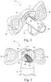
- the frame extension 14 includes a frame extension cylinder 30.
- the frame extension cylinder 30 includes a bore 36.
- a cantilevered lever 34 is formed in an outer peripheral surface of the frame extension cylinder 30.
- a lock mechanism release button 32 is provided on the free end of the lever 34.
- the cushion frame 12 includes a shaft 40 that is received in the bore 36 of the frame extension cylinder 30.
- the shaft 40 is also in the form of a cylinder.
- a biasing element 42 e.g. a compression coil spring, is provided inside the shaft 40.
- the biasing element 42 may be secured to the cushion frame 12 at the end of the shaft, i.e., on the portion of the cushion frame 12 that supports the cushions 25.
- the mask stabilizer 10 may be adjusted to control the deflection of the mask cushion 19, for example in the region of the patient's nasal bridge.
- the frame extension cylinder 30 includes radial projections 38 on the inner cylindrical surface of the cylinder 30.
- the radial projections 38 extend axially along the cylinder 30.
- the radial projections 38 are received in radial grooves 44 formed in the outer circumferential surface of the shaft 40 of the cushion frame 12.
- the frame extension cylinder 30 and the shaft 40 of the cushion frame 12 are shown having circular cross-sections, it should be appreciated that the cylinder and shaft may have a polygonal cross-section, for example.
- the lock mechanism release button 32 has a pawl 50 which extends from the release button 32 radially inward of the frame extension cylinder 30.
- the pawl 50 has ratchet teeth 52 provided on opposite sides.
- the pawl 50 and the release button 32 are resiliently supported at the end of the cantilevered lever 34.
- the shaft 40 of the cushion frame 12 includes an axial slot 45.
- the slot 45 includes ratchet teeth 46 on each side.
- the pawl 50 of the lock release button 32 is received in the axial slot 45 of the shaft 40 so that the ratchet teeth 52 of the pawl 50 engage the ratchet teeth 46 of the axial slot 45.
- the engagement of the radial projections 38 of the frame extension cylinder 30 into the radial grooves 44 of the shaft 40 of the cushion frame 12 ensure that the cushion frame 12 and the frame extension cylinder 30 are properly aligned for assembly of the mask stabilizer 10.
- the position shown in Fig. 5 is the locked position of the auto-adjusting mask stabilizer 10 and relative movement between the cushion frame 12 and the mask extension 14 is prevented, or locked, by the engagement of the ratchet teeth 52 of the pawl 50 with the ratchet teeth 46 of the slot 45 or by high friction coefficient material on the pawl 50 and/or the ratchet teeth 52 to lock the movement, e.g. a clutch.
- the biasing element 42 operates to bias the shaft 40 of the cushion frame 12 away from the cylinder 30 of the frame extension 14.
- the lock mechanism When the lock mechanism is in the position shown in Fig. 5 , movement of the cushion frame 12 caused by the biasing force of the biasing element 42 away from the frame extension 14 is prevented by the engagement of the ratchet teeth 52 with the ratchet teeth 46.
- the release button 32 In order to release the lock mechanism, the release button 32 is pressed downwardly to release the engagement of the ratchet teeth 52 from the ratchet teeth 46.
- the biasing element 42 biases the cushion frame 12 in a direction away from the frame extension 14 toward the forehead of the patient.
- the engagement of the shaft 40 of the cushion frame 12 into the bore 36 of the mask extension cylinder 30 allows the cushion frame 12 to translate with respect to the mask frame 17.
- the inclination between the cushion pads 25 and the patient's forehead does not change during adjustment, i.e., movement of the cushion frame 12 with respect to frame extension 14.
- the mask stabilizer 10 of the present invention thus provides the ability to stabilize the vertical angle of the position of the mask 16 relative to the patient's forehead and also stabilizes the relative set position of the mask 16 throughout the patient's sleep session.
- the shaft 40 of the cushion frame 12 is fully inserted into the mask extension cylinder 30.
- the biasing element 42 is under compression and the forehead pads 25 are in the most outward set position so that the compression of the biasing element 42 is at a maximum and the forehead pads 25 are at their closest position to the frame extension 14.
- the mask 16 is placed in contact with the patient's face and adjusted so that a good seal and comfortable fit are obtained.
- the lock mechanism release button 32 is then pressed down and the engagement between the ratchet teeth 52 and the ratchet teeth 46 is released.
- the biasing element 42 then acts to bias the cushion frame 12 toward the patient's forehead and into contact with the patient's forehead.
- the lock mechanism release button 32 is released and the lock mechanism returns to the locked position (i.e. the ratchet teeth 52 of the pawl 50 return to engagement with the ratchet teeth 46 of the slot 45).
- Fine tuning of the fit may be achieved by re-pressing the release button 32, which releases the lock mechanism, and moving the mask 16 relative to the patient's face. Once the fine tuning is complete, the release button 32 is again released and the lock mechanism returns to the locked position to lock the cushion frame 12 into position.
- the adjustment may be performed with one hand.
- the patient, or clinic worker simply presses the release button 32 and adjusts the position of the mask 16 with the same hand used to depress the release button 32.
- This allows adjustment of the fit of the mask 16 according to the present invention in a quicker manner than mask systems of the prior art.
- a mask system including the auto-adjusting stabilizer according to the invention may be initially fit in under one second, almost instantaneously, as opposed to up to five seconds as may be required for forehead supports according to the prior art.
- the mask system of the present invention requires less dexterity to adjust than masks of the prior art.
- the biasing element 42 may be a coiled compression spring.
- the spring could be a stainless steel or nickel-plated spring.
- the biasing element 42 may take other forms.
- the biasing element 42 may be a compressible open cell foam or silicone rubber elastic band.
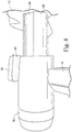
- the biasing element 42 may be an air spring having a reservoir, or an air bladder or integrally spring-loaded bellows 42a with an elastic memory so as the air is compressed the bladder can stretch and provide a spring force.
- the air bladder may be in communication with the air being delivered to the mask so that an air line 60 is provided between the inside of the mask frame and the air bladder or bellows 42a so that the air bladder or bellows 42a is under the influence of air pressure which influences or biases the movement of the cushion frame 12 toward the patient's face.
- the air bladder may be provided with a valve 62 allowing the deflation of the air bladder. In operation, the air bladder or bellows 42a is normally in an extended position. Prior to fitting the mask to the patient, the valve 60 is opened and the air bladder or bellows 42a is compressed during fitting. The valve 60 is then closed to fix the support in position.
- a bushing 61 may be provided between the release button 32 and the outer surface of the mask extension cylinder 30.
- the bushing 61 serves to adjust the force required to depress the release button 32.
- the bushing 61 may also serve to prevent accidental release of the locking mechanism, for example during movement of the patient during the sleep session.
- the bushing 61 may also bias the locking mechanism into the locked position.
- the lock mechanism release button 32 is shown in the attached drawings as being provided on top of the mask frame extension cylinder 30, it should be appreciated that the release button could also be provided anywhere along the circumference of the mask frame extension cylinder 30, with a corresponding movement of the slot 45 and ratchet teeth 46 of the shaft 40 of the cushion frame 12. It should also be appreciated that the release button could be provided at the closed end of the mask frame extension cylinder 30. However, positioning the release button 32 on top of the frame extension cylinder 30 allows the patient to activate the release button in a natural way and the force that is required to activate the release button is in a plane normal to the direction along which the patient or fitter is positioning the mask. This minimizes the chance of moving the mask while adjusting the position of the cushion frame 12.
- Spacing of the ratchet teeth 46 in the slot 45 of the shaft 40 of the cushion frame 12 may be, for example, 1 mm.
- the position of the cushion frame 12 may thus be adjusted in 1 mm increments. It should be appreciated, however, that other spacings of the ratchet teeth 46 are within the spirit and scope of the invention.
- an auto-adjusting stabilizer includes a frame extension 14a having a frame extension cylinder 30a.
- a shaft 40a of a cushion frame (not shown) is received in the frame extension cylinder 30a.
- a biasing element (not shown) is provided between the cylinder 30a and the shaft 40a to bias the shaft 40a relative to the frame 30a.
- Radial projections 38a of the frame extension cylinder 30a frictionally engage the outer surface of the shaft 40a to retain the shaft 40a against movement relative to the cylinder 30a caused by the biasing element.
- a lock mechanism release button 32a is provided for releasing the engagement of the radial projections 38a from the shaft 40a to permit relative movement between the shaft 40a and the cylinder 30a by the biasing element. Depressing the release button 32a causes the cylinder 30a to deform, thus disengaging the projections 38a from the cylinder 40a.
- a lock mechanism 32j includes a lock mechanism release button 32b engagable by the patient or clinician.
- the release button 32b is supported by a release button support 32c.
- the release button support 32c includes a cylindrical portion 32d that receives a release mechanism sleeve 32e.
- the sleeve 32e is concentrically supported by the cylindrical portion 32d to permit relative movement between the release button support 32c and the sleeve 32e.
- Resilient, curved legs 32f couple the support 32c to the sleeve 32e and a cylindrical plug 32g connected to the release button 32b couples the release button 32b to the support 32c.
- a biasing element 32k e.g., a spring, is provided between the cylindrical plug 32g and a cross element 32i in the sleeve 32e to bias the lock mechanism 32 into the position shown in Fig. 10 .
- Depressing the release button 32b causes the plug 32g to compress the biasing element 32k.
- the biasing element 32k is initially compressed by movement of the release button 32b, and then transfers further depression of the release button 32b to the sleeve 32e through engagement of the biasing element and the cross element 32i.
- the release button 32b of the lock release mechanism includes a pawl 50b.
- the pawl 50b includes an engagement surface 53 on each side that engages a corresponding engagement surface 47 of the slot 45b of the shaft 40b of the cushion frame to lock the cushion frame in position.
- the engagement surfaces 53 of the pawl 50b and the engagement surfaces 47 of the slot 45b may be textured, such as by knurling, to increase the friction between the pawl 50b and the sides of the slot 45b.
- the use of a friction lock would provide for continuous, or infinite, variability of the position of the cushion frame 12 with respect to the mask 16.
- Figs. 11 and 12 include a space between the engagement surfaces 47 and 53 for illustrative purposes, it should be appreciated that the surfaces are in contact.
- the release button 32b is biased into the locked position shown in Fig. 11 and 12 by a biasing element 32k, e.g., a spring.
- a projecting rim 41b in the slot 45b of the shaft 40b engages a shoulder 33b of the release button 32b to maintain the release button 32b in the locked position shown in Fig. 11 .
- the release button 32b is depressed, as shown in Fig. 12 , the amount of engagement between the engagement surfaces 47 and 53 is reduced and the amount of friction is correspondingly reduced.
- the shaft 40b of the cushion frame is then movable relative to the mask extension cylinder that supports the release button 32b to permit adjustment of the position of the cushion frame.
- the cushion frame 12 may include a flexible member 72 which has two side by side spaced apart tongues 74 and a middle protruding button 76 on its distal end.
- the frame extension14 may include two generally arcuate shaped portions 78 that each have a pair of four grooves 80. It should be appreciated that the pair of four grooves is merely an example and that only two or more grooves are required. It should also be appreciated that the flexible member 72 can be on the frame extension 14 and the grooves 40 can be on the cushion frame 12.
- the tongue 74 and the grooves 80 extend in a direction substantially parallel to a line extending radially from the axis 70.
- the cushion frame 12 may be constructed from a plastic material, such as polypropylene or polycarbonate, which allows the member 72 to be flexed relative to the cushion frame 12 upon which is mounted when pressure is applied to the button 76 in the direction of arrow 82.
- the corresponding movement of the tongues 74 releases them from engagement with one of the pairs of grooves 80 (as shown in Fig. 15 ) to allow angular adjustment between the cushion frame 12 and the joining member 14 about the axis 30.
- Releasing the button 76 allows the tongue 74 to resiliently flex back towards the grooves 80.
- the tongues 74 and one of the pairs of grooves 80 are aligned (as shown in Fig. 14 ) the tongues 74 engage one of the pair of grooves 80.
- the cushion frame 12 and joining member 14 are locked against pivotal movement therebetween at a predetermined angle.
- a biasing member such as a torsion spring (not shown), may be provided between the cushion frame 12 and the mask extension 14 to bias the cushion frame 12 into a position when the button 76 is released.
- the biasing member may be configured to bias the cushion frame 12 toward the face of the patient when the button 76 is pressed.
- the biasing member may be configured to bias the cushion frame 12 away from the face of the patient when the button 76 is pressed.
- the cushions 25 may be supported on the cushion frame 12 by a resilient member 90.
- the resilient member 90 may be a silicone rubber stem-like member. As the cushion frame 12 rotates about the axis 70, the resilient member 90 is able to flex or bend to maintain the contact face of the cushion 25 flush against the face of the patient, e.g. against the patient's forehead.
- the auto-adjusting mask stabilizer may be incorporated into any mask system where the fitting and correct adjustment of the mask relative to the wearer's head or face can be achieved.
- the auto-adjusting mask stabilizer of the invention may be used in mask systems that are not provided with a forehead support, but instead utilize, for example, a cheek support or upper lip support.
- the auto-adjusting mask stabilizer of the invention may be utilized in a mask system in which the forehead support is located or otherwise attached to a headgear system.
- the auto-adjusting mask stabilizer may not include a lock mechanism. In such case, the cushion frame would be biased against the patient's head, e.g., forehead, by the biasing element and its position would self-adjust to the patient.
Applications Claiming Priority (3)
| Application Number | Priority Date | Filing Date | Title |
|---|---|---|---|
| US94538007P | 2007-06-21 | 2007-06-21 | |
| EP08158797.4A EP2005985B1 (fr) | 2007-06-21 | 2008-06-23 | Stabilisateur de masque auto-réglable |
| EP14169108.9A EP2826512B1 (fr) | 2007-06-21 | 2008-06-23 | Stabilisateur de masque auto-réglable |
Related Parent Applications (2)
| Application Number | Title | Priority Date | Filing Date |
|---|---|---|---|
| EP14169108.9A Division EP2826512B1 (fr) | 2007-06-21 | 2008-06-23 | Stabilisateur de masque auto-réglable |
| EP08158797.4A Division EP2005985B1 (fr) | 2007-06-21 | 2008-06-23 | Stabilisateur de masque auto-réglable |
Publications (1)
| Publication Number | Publication Date |
|---|---|
| EP3351284A1 true EP3351284A1 (fr) | 2018-07-25 |
Family
ID=39745284
Family Applications (3)
| Application Number | Title | Priority Date | Filing Date |
|---|---|---|---|
| EP14169108.9A Active EP2826512B1 (fr) | 2007-06-21 | 2008-06-23 | Stabilisateur de masque auto-réglable |
| EP08158797.4A Active EP2005985B1 (fr) | 2007-06-21 | 2008-06-23 | Stabilisateur de masque auto-réglable |
| EP18162340.6A Withdrawn EP3351284A1 (fr) | 2007-06-21 | 2008-06-23 | Stabilisateur de masque auto-réglable |
Family Applications Before (2)
| Application Number | Title | Priority Date | Filing Date |
|---|---|---|---|
| EP14169108.9A Active EP2826512B1 (fr) | 2007-06-21 | 2008-06-23 | Stabilisateur de masque auto-réglable |
| EP08158797.4A Active EP2005985B1 (fr) | 2007-06-21 | 2008-06-23 | Stabilisateur de masque auto-réglable |
Country Status (3)
| Country | Link |
|---|---|
| US (2) | US9707367B2 (fr) |
| EP (3) | EP2826512B1 (fr) |
| NZ (1) | NZ569187A (fr) |
Families Citing this family (38)
| Publication number | Priority date | Publication date | Assignee | Title |
|---|---|---|---|---|
| US9155855B2 (en) | 2002-12-06 | 2015-10-13 | Fisher & Paykel Healthcare Limited | Mouthpiece |
| US8783257B2 (en) | 2004-02-23 | 2014-07-22 | Fisher & Paykel Healthcare Limited | Breathing assistance apparatus |
| WO2005094928A1 (fr) | 2004-04-02 | 2005-10-13 | Fisher & Paykel Healthcare Limited | Appareil d'assistance a la respiration |
| CN102512739B (zh) * | 2006-06-16 | 2015-11-25 | 瑞思迈有限公司 | 面罩的前额支架 |
| US11660413B2 (en) | 2008-07-18 | 2023-05-30 | Fisher & Paykel Healthcare Limited | Breathing assistance apparatus |
| CA2761741C (fr) * | 2009-05-12 | 2017-04-25 | Fisher & Paykel Healthcare Limited | Interface pour patient et aspects correspondants |
| WO2010133218A2 (fr) * | 2009-05-18 | 2010-11-25 | Weinmann Geräte für Medizin GmbH + Co. KG | Appareil d'assistance respiratoire à dispositif de fixation |
| PL2453989T3 (pl) * | 2009-07-17 | 2020-05-18 | Cleanspace Ip Pty Ltd. | Maska oddechowa |
| US8176919B2 (en) * | 2009-10-28 | 2012-05-15 | Hsiner Co., Ltd. | Respiratory mask including an adjustable forehead abutment member |
| ES2425744T3 (es) * | 2009-12-02 | 2013-10-17 | Air Liquide Medical Systems | Mascarilla respiratoria nasal con brazo pivotante para sujetar y orientar el soporte delantero |
| USD679799S1 (en) | 2010-01-08 | 2013-04-09 | Resmed Limited | Mask assembly |
| US20110209708A1 (en) * | 2010-02-26 | 2011-09-01 | New York University | Ventilation Interface Device |
| WO2011110968A2 (fr) * | 2010-03-12 | 2011-09-15 | Koninklijke Philips Electronics N.V. | Dispositif d'interface pour patient avec réglage dynamique du masque |
| TWI396566B (zh) * | 2010-07-16 | 2013-05-21 | Apex Medical Corp | 陽壓呼吸面罩的可置換額墊 |
| US9561338B2 (en) | 2010-10-08 | 2017-02-07 | Fisher & Paykel Healthcare Limited | Breathing assistance apparatus |
| US9446214B2 (en) | 2011-03-18 | 2016-09-20 | Koninklijke Philips N.V. | Patient interface device including a moveable wedge forehead adjustment assembly |
| EP2707070A1 (fr) * | 2011-05-12 | 2014-03-19 | Koninklijke Philips N.V. | Dispositif d'interface de patient comprenant un support de front à réglage pneumatique |
| RU2604700C2 (ru) | 2011-05-17 | 2016-12-10 | Конинклейке Филипс Н.В. | Регулируемая фиксирующая налобная опора для устройства интерфейса с пациентом |
| WO2012156929A2 (fr) * | 2011-05-17 | 2012-11-22 | Koninklijke Philips Electronics N.V. | Support de front réglable à élément souple et renvoi à des applications connexes |
| ES2704823T3 (es) * | 2011-07-01 | 2019-03-20 | Fisher & Paykel Healthcare Ltd | Conjunto de interfaz de máscara nasal |
| MX343065B (es) * | 2011-11-15 | 2016-10-24 | Koninklijke Philips Nv | Dispositivo de interfaz de paciente con ajuste para el puente de la nariz. |
| EP2601993B1 (fr) * | 2011-12-07 | 2018-02-14 | Löwenstein Medical Technology S.A. | Dispositif destiné au positionnement d'une interface patient |
| CN103182126B (zh) * | 2011-12-29 | 2017-04-12 | 皇家飞利浦电子股份有限公司 | 具有可调节前额支撑件的患者界面系统 |
| EP2858705B1 (fr) | 2012-06-08 | 2018-10-24 | Koninklijke Philips N.V. | Interface patient avec coussin pour prévenir les marques rouges |
| WO2013190421A1 (fr) * | 2012-06-20 | 2013-12-27 | Koninklijke Philips N.V. | Système d'interface de patient ayant une attache de tampon avant articulée |
| EP2863978A1 (fr) * | 2012-06-22 | 2015-04-29 | Koninklijke Philips N.V. | Dispositif d'interface patient |
| CN104428028B (zh) | 2012-07-03 | 2017-06-23 | 皇家飞利浦有限公司 | 患者界面系统 |
| JP6581501B2 (ja) * | 2012-07-11 | 2019-09-25 | コーニンクレッカ フィリップス エヌ ヴェKoninklijke Philips N.V. | 患者インターフェース |
| JP2015521936A (ja) * | 2012-07-11 | 2015-08-03 | コーニンクレッカ フィリップス エヌ ヴェ | 患者インターフェイス |
| WO2014009838A1 (fr) * | 2012-07-11 | 2014-01-16 | Koninklijke Philips N.V. | Interface patient |
| DE102013018897A1 (de) * | 2012-11-15 | 2014-05-15 | Weinmann Geräte für Medizin GmbH + Co. KG | Vorrichtung zur Positionierung eines Patienten Interfaces |
| US20140230822A1 (en) * | 2013-02-20 | 2014-08-21 | Yen-Ting Kuo | Forehead Abutting Device for Use with Respiratory Mask without Adjustment Thereof |
| CN103536996B (zh) * | 2013-10-25 | 2015-10-28 | 长沙比扬医疗器械有限公司 | 一种呼吸面罩前额支撑架及具有该支撑架的呼吸面罩 |
| USD754328S1 (en) | 2014-05-22 | 2016-04-19 | Intersurgical Ag | Respiratory mask |
| CN104906676B (zh) * | 2015-06-23 | 2017-11-14 | 北京怡和嘉业医疗科技股份有限公司 | 一种面罩组件 |
| USD895105S1 (en) | 2016-10-24 | 2020-09-01 | ResMed Pty Ltd | Combined cushion and frame module for patient interface |
| US20180361093A1 (en) * | 2017-06-19 | 2018-12-20 | Loewenstein Medical Technology S.A. | Breathing mask interface with small required operating force |
| USD892304S1 (en) * | 2019-01-04 | 2020-08-04 | Sleepnet Corporation | Facemask pressure adjustment device |
Citations (9)
| Publication number | Priority date | Publication date | Assignee | Title |
|---|---|---|---|---|
| US4782832A (en) | 1987-07-30 | 1988-11-08 | Puritan-Bennett Corporation | Nasal puff with adjustable sealing means |
| US4944310A (en) | 1981-04-24 | 1990-07-31 | Somed Pty. Ltd. | Device for treating snoring sickness |
| EP0526824A2 (fr) * | 1991-08-07 | 1993-02-10 | Becton, Dickinson and Company | Pulvérisateur à seringue |
| US5243971A (en) | 1990-05-21 | 1993-09-14 | The University Of Sydney | Nasal mask for CPAP having ballooning/moulding seal with wearer's nose and facial contours |
| US5245995A (en) | 1987-06-26 | 1993-09-21 | Rescare Limited | Device and method for monitoring breathing during sleep, control of CPAP treatment, and preventing of apnea |
| WO1998005374A1 (fr) * | 1996-08-07 | 1998-02-12 | Vadus, Inc. | Montage protecteur a rochet pour aiguille |
| US6532961B1 (en) | 1999-06-18 | 2003-03-18 | Resmed Limited | Forehead support for facial mask |
| WO2006074517A1 (fr) * | 2005-01-12 | 2006-07-20 | Resmed Limited | Supports pour le front pour masques faciaux |
| WO2007143793A1 (fr) * | 2006-06-16 | 2007-12-21 | Resmed Ltd | Supports de front pour masques faciaux |
Family Cites Families (20)
| Publication number | Priority date | Publication date | Assignee | Title |
|---|---|---|---|---|
| US2984726A (en) * | 1959-01-26 | 1961-05-16 | Illinois Tool Works | Sealed push button control switch |
| US3904280A (en) * | 1973-12-28 | 1975-09-09 | Clegg Jr Giles C | Method and apparatus for determining the distance between the surface of an eye and a reference point |
| DE2549979C3 (de) * | 1975-11-07 | 1978-05-24 | Draegerwerk Ag, 2400 Luebeck | Schutzhelm kombiniert mit Atemschutzmaske |
| US4461551A (en) * | 1981-05-27 | 1984-07-24 | Carl-Zeiss-Stiftung | Portable ophthalmological instrument for selective examination of anterior or posterior regions of the eye |
| US4695252A (en) * | 1985-12-05 | 1987-09-22 | Ab Dentatus | Quick mount face-bow device for an articulator |
| DK0409784T3 (da) * | 1989-07-17 | 1994-07-25 | Draeger Joerg | Applanationstonometer |
| JPH08164114A (ja) * | 1994-12-12 | 1996-06-25 | Nikon Corp | 手持ち式眼科装置 |
| AUPP949999A0 (en) | 1999-03-29 | 1999-04-22 | Resmed Limited | Forehead support for facial mask II |
| JP3880294B2 (ja) * | 2000-07-19 | 2007-02-14 | キヤノン株式会社 | 頭部装着機構及びそれを用いた頭部装着装置 |
| DE10035946C2 (de) * | 2000-07-21 | 2002-06-27 | Map Gmbh | Halterung für eine Atemmaske |
| EP1205205B1 (fr) * | 2000-11-14 | 2005-06-15 | Weinmann Geräte für Medizin GmbH & Co. KG | Masque respiratoire muni d'un support frontal |
| US7047971B2 (en) * | 2003-10-03 | 2006-05-23 | Ric Investments, Llc. | Patient interface with forehead and chin support |
| DE102004002870B4 (de) * | 2004-01-19 | 2017-01-19 | Löwenstein Medical Technology S.A. | Atemmaske mit Stirnstütze |
| NZ551715A (en) * | 2004-06-16 | 2011-02-25 | Resmed Ltd | Single piece, gussetted cushion for a respiratory mask assembly |
| US7975692B2 (en) * | 2004-09-03 | 2011-07-12 | Weinmann Geräte für Medizin GmbH & Co. KG | Respiratory device |
| WO2006024288A2 (fr) * | 2004-09-03 | 2006-03-09 | Weinmann Geräte für Medizin GmbH & Co. KG | Masque respiratoire |
| US20070062537A1 (en) * | 2005-09-14 | 2007-03-22 | Paul Chiesa | Forehead support for a respiratory mask |
| US20080264422A1 (en) * | 2007-04-27 | 2008-10-30 | Fishman Graham A | Sleep apnea CPAP headgear |
| WO2010133218A2 (fr) * | 2009-05-18 | 2010-11-25 | Weinmann Geräte für Medizin GmbH + Co. KG | Appareil d'assistance respiratoire à dispositif de fixation |
| US8176919B2 (en) | 2009-10-28 | 2012-05-15 | Hsiner Co., Ltd. | Respiratory mask including an adjustable forehead abutment member |
-
2008
- 2008-06-06 US US12/134,871 patent/US9707367B2/en active Active
- 2008-06-18 NZ NZ569187A patent/NZ569187A/en unknown
- 2008-06-23 EP EP14169108.9A patent/EP2826512B1/fr active Active
- 2008-06-23 EP EP08158797.4A patent/EP2005985B1/fr active Active
- 2008-06-23 EP EP18162340.6A patent/EP3351284A1/fr not_active Withdrawn
-
2017
- 2017-06-09 US US15/618,798 patent/US20170274168A1/en not_active Abandoned
Patent Citations (9)
| Publication number | Priority date | Publication date | Assignee | Title |
|---|---|---|---|---|
| US4944310A (en) | 1981-04-24 | 1990-07-31 | Somed Pty. Ltd. | Device for treating snoring sickness |
| US5245995A (en) | 1987-06-26 | 1993-09-21 | Rescare Limited | Device and method for monitoring breathing during sleep, control of CPAP treatment, and preventing of apnea |
| US4782832A (en) | 1987-07-30 | 1988-11-08 | Puritan-Bennett Corporation | Nasal puff with adjustable sealing means |
| US5243971A (en) | 1990-05-21 | 1993-09-14 | The University Of Sydney | Nasal mask for CPAP having ballooning/moulding seal with wearer's nose and facial contours |
| EP0526824A2 (fr) * | 1991-08-07 | 1993-02-10 | Becton, Dickinson and Company | Pulvérisateur à seringue |
| WO1998005374A1 (fr) * | 1996-08-07 | 1998-02-12 | Vadus, Inc. | Montage protecteur a rochet pour aiguille |
| US6532961B1 (en) | 1999-06-18 | 2003-03-18 | Resmed Limited | Forehead support for facial mask |
| WO2006074517A1 (fr) * | 2005-01-12 | 2006-07-20 | Resmed Limited | Supports pour le front pour masques faciaux |
| WO2007143793A1 (fr) * | 2006-06-16 | 2007-12-21 | Resmed Ltd | Supports de front pour masques faciaux |
Also Published As
| Publication number | Publication date |
|---|---|
| US20170274168A1 (en) | 2017-09-28 |
| NZ569187A (en) | 2010-02-26 |
| US20080314390A1 (en) | 2008-12-25 |
| EP2005985A3 (fr) | 2009-03-18 |
| EP2826512B1 (fr) | 2018-03-21 |
| EP2005985B1 (fr) | 2014-05-21 |
| EP2826512A1 (fr) | 2015-01-21 |
| EP2005985A2 (fr) | 2008-12-24 |
| US9707367B2 (en) | 2017-07-18 |
Similar Documents
| Publication | Publication Date | Title |
|---|---|---|
| EP2005985B1 (fr) | Stabilisateur de masque auto-réglable | |
| EP1165166B1 (fr) | Support frontal pour masque facial | |
| AU2006279974B2 (en) | Patient interface with an adjustable cushion | |
| AU2004201915B2 (en) | Forehead Support for Facial Mask | |
| EP1621225B1 (fr) | Support frontal pour masque facial | |
| EP2452716B1 (fr) | Interface de patient | |
| AU2020202201A1 (en) | Breathing assistance apparatus | |
| EP2608835A1 (fr) | Système pap | |
| US20130098359A1 (en) | Nares mask and support apparatus | |
| WO2014045136A1 (fr) | Masque facial intégral articulé | |
| US11541197B2 (en) | Breathing assistance apparatus | |
| CN111936192A (zh) | 用于界面装置的可调节框架 | |
| US20140230820A1 (en) | Adjustable locking forehread support for a patient interface device | |
| US20150217071A1 (en) | Leak correction for a patient interface device | |
| AU774142B2 (en) | Forehead support for a facial mask | |
| AU2018201975A1 (en) | Breathing assistance apparatus |
Legal Events
| Date | Code | Title | Description |
|---|---|---|---|
| PUAI | Public reference made under article 153(3) epc to a published international application that has entered the european phase |
Free format text: ORIGINAL CODE: 0009012 |
|
| AC | Divisional application: reference to earlier application |
Ref document number: 2826512 Country of ref document: EP Kind code of ref document: P Ref document number: 2005985 Country of ref document: EP Kind code of ref document: P |
|
| AK | Designated contracting states |
Kind code of ref document: A1 Designated state(s): AT BE BG CH CY CZ DE DK EE ES FI FR GB GR HR HU IE IS IT LI LT LU LV MC MT NL NO PL PT RO SE SI SK TR |
|
| STAA | Information on the status of an ep patent application or granted ep patent |
Free format text: STATUS: THE APPLICATION IS DEEMED TO BE WITHDRAWN |
|
| 18D | Application deemed to be withdrawn |
Effective date: 20190126 |