EP3351172A1 - Procédé d'analyse de forme d'oreille, dispositif d'analyse de forme d'oreille, et procédé de génération de modèle de forme d'oreille - Google Patents
Procédé d'analyse de forme d'oreille, dispositif d'analyse de forme d'oreille, et procédé de génération de modèle de forme d'oreille Download PDFInfo
- Publication number
- EP3351172A1 EP3351172A1 EP16846180.4A EP16846180A EP3351172A1 EP 3351172 A1 EP3351172 A1 EP 3351172A1 EP 16846180 A EP16846180 A EP 16846180A EP 3351172 A1 EP3351172 A1 EP 3351172A1
- Authority
- EP
- European Patent Office
- Prior art keywords
- ear
- shape
- candidate
- ear shape
- image
- Prior art date
- Legal status (The legal status is an assumption and is not a legal conclusion. Google has not performed a legal analysis and makes no representation as to the accuracy of the status listed.)
- Granted
Links
- 238000000034 method Methods 0.000 title claims description 117
- 238000004458 analytical method Methods 0.000 title claims description 58
- 239000013598 vector Substances 0.000 claims abstract description 201
- 210000005069 ears Anatomy 0.000 claims description 78
- 239000011159 matrix material Substances 0.000 claims description 78
- 238000012546 transfer Methods 0.000 claims description 60
- 230000009466 transformation Effects 0.000 claims description 55
- 238000013519 translation Methods 0.000 claims description 51
- 238000013528 artificial neural network Methods 0.000 claims description 28
- 238000000513 principal component analysis Methods 0.000 claims description 16
- 230000006870 function Effects 0.000 description 85
- 230000008569 process Effects 0.000 description 83
- 238000012545 processing Methods 0.000 description 54
- 230000005236 sound signal Effects 0.000 description 37
- 238000003860 storage Methods 0.000 description 30
- 238000010586 diagram Methods 0.000 description 23
- 238000004364 calculation method Methods 0.000 description 21
- 230000008901 benefit Effects 0.000 description 19
- 238000004891 communication Methods 0.000 description 15
- 238000009826 distribution Methods 0.000 description 7
- 238000010801 machine learning Methods 0.000 description 6
- 238000010606 normalization Methods 0.000 description 5
- 230000004048 modification Effects 0.000 description 4
- 238000012986 modification Methods 0.000 description 4
- 241000282414 Homo sapiens Species 0.000 description 3
- 230000000694 effects Effects 0.000 description 3
- 230000002547 anomalous effect Effects 0.000 description 2
- 238000003384 imaging method Methods 0.000 description 2
- 238000009434 installation Methods 0.000 description 2
- 238000005304 joining Methods 0.000 description 2
- 230000003287 optical effect Effects 0.000 description 2
- 238000005457 optimization Methods 0.000 description 2
- 230000004044 response Effects 0.000 description 2
- 239000004065 semiconductor Substances 0.000 description 2
- 238000013179 statistical model Methods 0.000 description 2
- 230000001960 triggered effect Effects 0.000 description 2
- 238000004422 calculation algorithm Methods 0.000 description 1
- 238000000354 decomposition reaction Methods 0.000 description 1
- 238000005516 engineering process Methods 0.000 description 1
- 230000010365 information processing Effects 0.000 description 1
- 238000013178 mathematical model Methods 0.000 description 1
- 238000005259 measurement Methods 0.000 description 1
- 239000000203 mixture Substances 0.000 description 1
- 238000010295 mobile communication Methods 0.000 description 1
- 238000012821 model calculation Methods 0.000 description 1
- 238000011176 pooling Methods 0.000 description 1
- 230000001902 propagating effect Effects 0.000 description 1
- 238000009877 rendering Methods 0.000 description 1
Images


Classifications
-
- G—PHYSICS
- G06—COMPUTING; CALCULATING OR COUNTING
- G06T—IMAGE DATA PROCESSING OR GENERATION, IN GENERAL
- G06T7/00—Image analysis
- G06T7/60—Analysis of geometric attributes
-
- G—PHYSICS
- G06—COMPUTING; CALCULATING OR COUNTING
- G06T—IMAGE DATA PROCESSING OR GENERATION, IN GENERAL
- G06T17/00—Three dimensional [3D] modelling, e.g. data description of 3D objects
-
- A—HUMAN NECESSITIES
- A61—MEDICAL OR VETERINARY SCIENCE; HYGIENE
- A61B—DIAGNOSIS; SURGERY; IDENTIFICATION
- A61B5/00—Measuring for diagnostic purposes; Identification of persons
- A61B5/0059—Measuring for diagnostic purposes; Identification of persons using light, e.g. diagnosis by transillumination, diascopy, fluorescence
- A61B5/0077—Devices for viewing the surface of the body, e.g. camera, magnifying lens
-
- A—HUMAN NECESSITIES
- A61—MEDICAL OR VETERINARY SCIENCE; HYGIENE
- A61B—DIAGNOSIS; SURGERY; IDENTIFICATION
- A61B5/00—Measuring for diagnostic purposes; Identification of persons
- A61B5/103—Detecting, measuring or recording devices for testing the shape, pattern, colour, size or movement of the body or parts thereof, for diagnostic purposes
- A61B5/107—Measuring physical dimensions, e.g. size of the entire body or parts thereof
- A61B5/1077—Measuring of profiles
-
- A—HUMAN NECESSITIES
- A61—MEDICAL OR VETERINARY SCIENCE; HYGIENE
- A61B—DIAGNOSIS; SURGERY; IDENTIFICATION
- A61B5/00—Measuring for diagnostic purposes; Identification of persons
- A61B5/103—Detecting, measuring or recording devices for testing the shape, pattern, colour, size or movement of the body or parts thereof, for diagnostic purposes
- A61B5/107—Measuring physical dimensions, e.g. size of the entire body or parts thereof
- A61B5/1079—Measuring physical dimensions, e.g. size of the entire body or parts thereof using optical or photographic means
-
- G—PHYSICS
- G01—MEASURING; TESTING
- G01B—MEASURING LENGTH, THICKNESS OR SIMILAR LINEAR DIMENSIONS; MEASURING ANGLES; MEASURING AREAS; MEASURING IRREGULARITIES OF SURFACES OR CONTOURS
- G01B11/00—Measuring arrangements characterised by the use of optical techniques
- G01B11/24—Measuring arrangements characterised by the use of optical techniques for measuring contours or curvatures
-
- G—PHYSICS
- G06—COMPUTING; CALCULATING OR COUNTING
- G06T—IMAGE DATA PROCESSING OR GENERATION, IN GENERAL
- G06T19/00—Manipulating 3D models or images for computer graphics
- G06T19/20—Editing of 3D images, e.g. changing shapes or colours, aligning objects or positioning parts
-
- G—PHYSICS
- G06—COMPUTING; CALCULATING OR COUNTING
- G06T—IMAGE DATA PROCESSING OR GENERATION, IN GENERAL
- G06T7/00—Image analysis
-
- G—PHYSICS
- G06—COMPUTING; CALCULATING OR COUNTING
- G06T—IMAGE DATA PROCESSING OR GENERATION, IN GENERAL
- G06T7/00—Image analysis
- G06T7/10—Segmentation; Edge detection
- G06T7/149—Segmentation; Edge detection involving deformable models, e.g. active contour models
-
- G—PHYSICS
- G06—COMPUTING; CALCULATING OR COUNTING
- G06V—IMAGE OR VIDEO RECOGNITION OR UNDERSTANDING
- G06V20/00—Scenes; Scene-specific elements
- G06V20/60—Type of objects
- G06V20/64—Three-dimensional objects
- G06V20/653—Three-dimensional objects by matching three-dimensional models, e.g. conformal mapping of Riemann surfaces
-
- A—HUMAN NECESSITIES
- A61—MEDICAL OR VETERINARY SCIENCE; HYGIENE
- A61B—DIAGNOSIS; SURGERY; IDENTIFICATION
- A61B2503/00—Evaluating a particular growth phase or type of persons or animals
- A61B2503/12—Healthy persons not otherwise provided for, e.g. subjects of a marketing survey
-
- A—HUMAN NECESSITIES
- A61—MEDICAL OR VETERINARY SCIENCE; HYGIENE
- A61B—DIAGNOSIS; SURGERY; IDENTIFICATION
- A61B2576/00—Medical imaging apparatus involving image processing or analysis
- A61B2576/02—Medical imaging apparatus involving image processing or analysis specially adapted for a particular organ or body part
-
- G—PHYSICS
- G06—COMPUTING; CALCULATING OR COUNTING
- G06T—IMAGE DATA PROCESSING OR GENERATION, IN GENERAL
- G06T2207/00—Indexing scheme for image analysis or image enhancement
- G06T2207/20—Special algorithmic details
- G06T2207/20081—Training; Learning
-
- G—PHYSICS
- G06—COMPUTING; CALCULATING OR COUNTING
- G06T—IMAGE DATA PROCESSING OR GENERATION, IN GENERAL
- G06T2207/00—Indexing scheme for image analysis or image enhancement
- G06T2207/20—Special algorithmic details
- G06T2207/20084—Artificial neural networks [ANN]
-
- G—PHYSICS
- G06—COMPUTING; CALCULATING OR COUNTING
- G06T—IMAGE DATA PROCESSING OR GENERATION, IN GENERAL
- G06T2207/00—Indexing scheme for image analysis or image enhancement
- G06T2207/30—Subject of image; Context of image processing
- G06T2207/30196—Human being; Person
-
- G—PHYSICS
- G06—COMPUTING; CALCULATING OR COUNTING
- G06T—IMAGE DATA PROCESSING OR GENERATION, IN GENERAL
- G06T2207/00—Indexing scheme for image analysis or image enhancement
- G06T2207/30—Subject of image; Context of image processing
- G06T2207/30196—Human being; Person
- G06T2207/30201—Face
-
- H—ELECTRICITY
- H04—ELECTRIC COMMUNICATION TECHNIQUE
- H04S—STEREOPHONIC SYSTEMS
- H04S2420/00—Techniques used stereophonic systems covered by H04S but not provided for in its groups
- H04S2420/01—Enhancing the perception of the sound image or of the spatial distribution using head related transfer functions [HRTF's] or equivalents thereof, e.g. interaural time difference [ITD] or interaural level difference [ILD]
-
- H—ELECTRICITY
- H04—ELECTRIC COMMUNICATION TECHNIQUE
- H04S—STEREOPHONIC SYSTEMS
- H04S7/00—Indicating arrangements; Control arrangements, e.g. balance control
- H04S7/30—Control circuits for electronic adaptation of the sound field
- H04S7/302—Electronic adaptation of stereophonic sound system to listener position or orientation
- H04S7/303—Tracking of listener position or orientation
Definitions
- the present invention relates to a technology for analyzing an ear shape that is used in calculating head-related transfer functions.
- Head-related transfer functions may for instance be calculated from a sound recorded at the ear holes of either the head of a listener or a dummy head of a given shape.
- use of a dummy head for the calculation involves a problem in that the listener is unable to perceive a location of a sound image appropriately if the shape of the head of the listener and that of the dummy head do not match each other.
- Measuring a head-related transfer function directly from the head of the listener also involves a problem in that considerable physical and psychological burdens are imposed on the listener during measurement.
- Non-Patent Document 1 proposes a technique in which a head-related transfer function is calculated for a listener from images of the head of the listener that have been captured from different directions.
- the head shape of the listener is estimated by use of a morphing technique in which a standard head shape prepared in advance is deformed so as to resemble the head shape of the listener as captured in the images, and a head-related transfer function is calculated for the listener from the results of this estimation.
- Non-Patent Document 1 Dellepiane Matteo, et al. "Reconstructing head models from photographs for individualized 3D audio processing," Computer Graphics Forum. Vol.27 NO.7, Blackwell Publishing Ltd., 2008 .
- the head shape of the listener is estimated by moving (morphing) feature points that are extracted from images of the head of the listener, and there is a problem in that an unrealistic, collapsed head shape is estimated when an image process (e.g., extracting feature points) is not carried out appropriately.
- An inappropriate image process leads to a failure to estimate an ear shape with high precision.
- an object of the present invention is to reduce a probability of misestimating an ear shape used in calculating head-related transfer functions.
- an ear shape analysis method is implemented by a computer, the method including: generating an ear shape data set by applying a principal component weight vector to an ear shape model, the ear shape model indicating a relation between ear shape data sets and principal component weight vectors, each ear shape data set indicating a difference between a point group representing a three-dimensional shape of an ear and a point group representing a three-dimensional shape of a reference ear, and each principal component weight vector indicating weights of principal components of the corresponding ear shape data set; and identifying from the generated ear shape data set generated by an ear shape data generator an estimated three-dimensional shape of a target ear corresponding to a target ear image represented by image data.
- an estimated three-dimensional shape of the target ear is identified from ear shape data generated by applying a principal component weight vector to an ear shape model indicating a relation between ear shape data sets and principal component weight vectors. Accordingly, a probability of misestimating an ear shape is reduced, compared to a configuration in which the three-dimensional shape of a target ear is estimated by deforming (morphing) a given shape.
- An ear shape analysis device includes: an ear shape data generator configured to generate an ear shape data set by applying a principal component weight vector to an ear shape model, the ear shape model indicating a relation between ear shape data sets and principal component weight vectors, each ear shape data set indicating a difference between a point group representing a three-dimensional shape of an ear and a point group representing a three-dimensional shape of a reference ear, and each principal component weight vector indicating weights of principal components of the corresponding ear shape data set; and an ear shape identifier configured to identify, from the ear shape data set generated by the ear shape data generator, an estimated three-dimensional shape of a target ear corresponding to a target ear image represented by image data.
- an estimated three-dimensional shape of the target ear is identified from ear shape data generated by applying a principal component weight vector to an ear shape model representing a relation between ear shape data sets and principal component weight vectors. Accordingly, a probability of misestimating an ear shape can be reduced, compared to a configuration in which the three-dimensional shape of a target ear is estimated by deforming a given shape.
- An ear shape model generation method is implemented by a computer to generate an ear shape model used in generating a candidate ear image for comparison with a target ear image represented by image data, the method including: generating, for a plurality of sample ears, a plurality of ear shape data sets, each indicating a difference between a point group representing a three-dimensional shape of a corresponding sample ear and a point group representing a three-dimensional shape of a reference ear, and calculating a transformation matrix for translating ear shape data into a principal component weight vector indicating weights of principal components, by performing principal component analysis on the plurality of generated ear shape data sets, to generate the ear shape model including the transformation matrix or an inverse matrix of the transformation matrix.
- the ear shape model used in estimating the three-dimensional shape of the target ear reflects statistical tendencies of three-dimensional shapes of a plurality of sample ears. Accordingly, an advantage is obtained in that the three-dimensional shape of the target ear can be estimated with high precision.
- Fig. 1 is a block diagram showing a configuration of an audio processing device 100 according to a first embodiment of the present invention.
- a signal supply device 12 and a sound output device 14 are connected to the audio processing device 100 of the first embodiment.
- the signal supply device 12 supplies an audio signal X A representing a sound, such as a voice and a music sound, to the audio processing device 100.
- Specific examples of the signal supply device 12 include: a sound receiving device that receives a sound in the surroundings to generate an audio signal X A ; and a playback device that acquires an audio signal X A from a recording medium (either portable or in-built) and supplies the same to the audio processing device 100.
- the audio processing device 100 is a signal processing device that generates an audio signal X B by applying audio processing to the audio signal X A supplied from the signal supply device 12.
- the audio signal X B is a stereo signal having two (left and right) channels.
- the audio processing device 100 generates the audio signal X B by convolving a head-related transfer function (HRTF) F of a specific user (hereinafter, "subject") into the audio signal X A .
- the sound output device 14 headphones, earphones, etc.
- a user listening to a playback sound output from the sound output device 14 is able to clearly perceive a location of a sound source of a sound component.
- a D/A converter which converts the audio signal X B generated by the audio processing device 100 from digital to analog, has been omitted from the drawings. Both or either one of the signal supply device 12 and the sound output device 14 may be mounted in the audio processing device 100.
- the audio processing device 100 is realized by a computer system including a control device 22 and a storage device 24.
- the storage device 24 stores therein a program executed by the control device 22 and various data used by the control device 22.
- a freely-selected form of well-known storage media such as a semiconductor storage medium and a magnetic storage medium, or a combination of various types of storage media may be employed as the storage device 24.
- a configuration in which the audio signal X A is stored in the storage device 24 (accordingly, the signal supply device 12 may be omitted) is also preferable.
- the control device 22 is an arithmetic unit (such as a central processing unit (CPU)), and by executing the program stored in the storage device 24, realizes different functions (an ear shape model generator 30, an ear shape analyzer 40, and an audio processor 50).
- a configuration in which the functions of the control device 22 are dividedly allocated to a plurality of devices, or a configuration which employs electronic circuitry that is dedicated to realize part of the functions of the control device 22, are also applicable.
- the ear shape model generator 30 generates a statistical model (hereinafter, "ear shape model”) E, which reflects statistical tendencies of shapes of a large number of ears that are prepared in advance as samples (hereinafter, “sample ears”).
- ear shape model a statistical model
- sample ears a statistical model
- the ear shape analyzer 40 estimates a shape of an ear of the subject (hereinafter, “target ear”) using the ear shape model E generated by the ear shape model generator 30, and based on the estimated shape of the target ear, generates a head-related transfer function F from a given direction up to either ear hole of the subject.
- the audio processor 50 convolves the head-related transfer function F generated by the ear shape analyzer 40 into the audio signal X A , so as to generate the audio signal X B .
- control device 22 Details of elements realized by the control device 22 will be described below.
- Fig. 2 is a block diagram showing a configuration of the ear shape model generator 30.
- the storage device 24 of the first embodiment stores three-dimensional shape data D 0 for each of N sample ears (N is a natural number of 2 or more) and one ear prepared in advance (hereinafter, "reference ear"). For example, from among a large number of ears (e.g., right ears) of a large number of unspecified human beings for whom three-dimensional shapes of these ears were measured in advance, one specific ear is selected as the reference ear while the rest of the ears are selected as sample ears, and three-dimensional shape data D 0 is generated for each of the selected ears.
- N is a natural number of 2 or more
- reference ear for example, from among a large number of ears (e.g., right ears) of a large number of unspecified human beings for whom three-dimensional shapes of these ears were measured in advance, one specific ear is selected as the reference ear while the rest of the ears are selected as sample ears, and three-
- Each three-dimensional shape data D 0 represents a three-dimensional shape of each of the sample ears and the reference ear.
- polygon mesh data representing an ear shape in a form of a collection of polygons may preferably be used as the three-dimensional shape data D 0 , for example.
- the ear shape model generator 30 of the first embodiment includes a point group identifier 32, a sample ear analyzer 34, and a statistics processor 36.
- the point group identifier 32 identifies a collection of multiple points (hereinafter, "point group") representing a three-dimensional shape of each sample ear and a point group representing a three-dimensional shape of the reference ear.
- the sample ear analyzer 34 generates, for each of the N sample ears, ear shape data v (n) (one among ear shape data v (1) to v (N) ) indicating a difference between a point group P S(n) of a sample ear and the point group P R of the reference ear, the point groups P S(n) and P R having been identified by the point group identifier 32.
- Fig. 3 is a flowchart showing a flow of a process S A2 for generating ear shape data v (n) of any one of the sample ears (hereinafter, "sample ear analysis process”), the process being executed by the sample ear analyzer 34.
- sample ear analysis process N ear shape data v (1) to v (N) are generated.
- the sample ear analyzer 34 Upon start of the sample ear analysis process S A2 , the sample ear analyzer 34 performs point matching (associates) between a point group P S(n) of one sample ear to be processed and (with) the point group P R of the reference ear in three-dimensional space (S A21 ). Specifically, for each of the plurality of points p R (p R1 , p R2 , ...) included in the point group P R of the reference ear, the sample ear analyzer 34 identifies a corresponding point p S (P S1 , p S2 , ...) in the point group P S(n) , as shown in Fig. 4 .
- a freely-selected one of publicly-known methods can be employed.
- the preferable methods is the method disclosed in Chui, Halil, and Anand Rangarajan, "A new point matching algorithm for non-rigid registration,” Computer Vision and Image Understanding 89.2 (2003); 114-141 , or the method disclosed in Jian, Bing, and Baba C. Vemuri, "Robust point set registration using Gaussian mixture models,” Pattern Analysis and Machine Intelligence, IEEE Transaction on 33.8(2011);1633-1645 .
- the sample ear analyzer 34 For each of m A points p R (m A is a natural number of 2 or more) constituting the point group P R of the reference ear, the sample ear analyzer 34 generates a vector ⁇ indicating a difference between each point p R and a corresponding point ps in a point group P S(n) of a sample ear (S A22 ) (this vector will hereinafter be referred to as a "translation vector").
- a freely selected translation vector ⁇ is a three-dimensional vector, elements of which are constituted by coordinate values of axes set in three-dimensional space.
- a translation vector ⁇ of a point p R in the point group P R expresses a location of a point p S of the point group P S(n) in three-dimensional space, based on the point p R serving as a point of reference. That is, as a result of a translation vector ⁇ of a point p R in the point group P R being added to the point p R , a point p S corresponding to the point p R in a point group P S(n) is reconstructed.
- a translation vector ⁇ corresponding to a point p R in the point group P R of the reference ear may be expressed as a vector (warping vector) that serves to move or translate the point P R to another point (a point ps in a point group P S(n) ) corresponding to the point p R .
- the sample ear analyzer 34 generates ear shape data v (n) of a sample ear (S A23 ), the ear shape data v (n) including m A translation vectors ⁇ generated by the above procedure.
- ear shape data v (n) that indicates a difference between a point group P S(n) representing a three-dimensional shape of a freely selected sample ear and the point group P R representing the three-dimensional shape of the reference ear.
- the statistics processor 36 in Fig. 2 calculates a transformation matrix W by performing principal component analysis on the N ear shape data v (1) to v (N) generated by the sample ear analyzer 34 in the sample ear analysis process S A2 described above.
- the transformation matrix W as expressed by equation (1) below, is a square matrix with M rows and M columns, which serves to translate ear shape data v (n) into a principal component weight vector w (n) .
- a principal component weight vector w (n) is an M-dimensional vector, elements of which are respective weights of M principal components.
- the sign ⁇ in equation (1) stands for a mean vector of the N ear shape data v (1) to v (N) .
- the statistics processor 36 of the first embodiment generates an ear shape model E including the transformation matrix W and the mean vector ⁇ .
- w n W v n ⁇ ⁇
- Fig. 5 is a flowchart showing a flow of a process S A3 executed by the statistics processor 36 of the first embodiment, wherein the statistics processor 36 calculates the transformation matrix W by performing principal component analysis on the N ear shape data v (1) to v (N) (this process will hereinafter be referred to as a "statistics process").
- the statistics process S A3 shown in Fig. 5 is started by being triggered by the generation of the N ear shape data v (1) to v (N) by the sample ear analyzer 34.
- the statistics processor 36 calculates a covariance matrix C of a matrix V in which the N ear shape data v (1) to v (N) generated by the sample ear analyzer 34 are arranged laterally, and which has M rows and N columns (the matrix V will hereinafter be referred to as an "ear shape matrix” V) (S A31 ).
- the sign "T” in equation (2) stands for transpose of a matrix.
- the statistics processor 36 performs an eigenvalue decomposition expressed by equation (3) below on the covariance matrix C of the ear shape matrix V, thereby calculating matrices L and U (S A32 ).
- C UL U T
- the statistics processor 36 calculates equation (4) below in which the matrices L and U calculated by calculation of equation (3) are used, thereby calculating a transformation matrix W (S A33 ).
- W L ⁇ 0.5 U T
- the statistics processor 36 calculates a mean vector ⁇ of the N ear shape data v (1) to v (N) (S A34 ).
- S A34 a statistics process S A3 in which the statistics processor 36 calculates a transformation matrix W by performing principal component analysis on the N ear shape data v (1) to v (N) (ear shape matrix V).
- Fig. 6 is a flowchart showing a flow of a process S A for generating an ear shape model E (hereinafter, "ear shape model generation process"), the process being executed by the ear shape model generator 30 of the first embodiment described above.
- the ear shape model generation process S A in Fig. 6 is executed when, for example, an instruction is given by the user to generate the ear shape model E.
- the point group identifier 32 identifies the point group P R of the reference ear and the point groups P S(n) (P S(1) to P S(N) ) of the N sample ears from the respective sets of three-dimensional shape data D 0 of the reference ear and the N sample ears (S A1 ).
- the sample ear analysis process S A2 S A21 to S A23 ) in Fig.
- the sample ear analyzer 34 generates the N ear shape data v (1) to v (N) (each corresponding to a different sample ear) from the point group P R of the reference ear and the point groups P S(n) of the sample ears that have been identified by the point group identifier 32.
- the statistics processor 36 executes the statistics process S A3 in Fig. 5 , which includes the principal component analysis of the N ear shape data v (1) to v (N) generated by the sample ear analyzer 34 (S A31 ) to S A33 ), and thereby generates an ear shape model E including the transformation matrix W and the mean vector ⁇ .
- the ear shape model E generated in the statistics process S A3 is stored in the storage device 24 (S A4 ).
- the ear shape model E reflecting statistical tendencies of shapes of the N sample ears is generated.
- the ear shape model E is a statistical model indicating a relation between ear shape data sets v (n) and a principal component weight vectors w (n) .
- Fig. 7 is a block diagram showing a configuration of the ear shape analyzer 40. As shown in Fig. 7 , there is stored in the storage device 24 of the first embodiment image data D G representing an external appearance of the target ear of the subject.
- the subject (or an assistant present near the subject) captures an image of the target ear using an image-capturing device mounted in an information terminal, such as a portable telephone and a smartphone, or a dedicated image-capturing device, such as a digital still camera.
- the image of the target ear is captured in a state where an index of a magnification ratio of the image capture (for example, a sticker of a prescribed size) is attached to the target ear.
- Image data D G representative of an image G U of the target ear of the subject captured by the above method (hereinafter, "target ear image") is stored in the storage device 24.
- the ear shape analyzer 40 of the first embodiment includes an ear shape data generator 42, an ear shape identifier 44, and a function calculator 48.
- the ear shape data generator 42 generates ear shape data v (k) (v (1) to v (K) ) (K is a natural number of 2 or more) for each of the K different candidate ears.
- ear shape data v (k) of a freely selected candidate ear indicates a difference between the point group P R of the reference ear and a point group P C(k) representing a three-dimensional shape of that candidate ear, as does the aforementioned ear shape data v (n) of the sample ear.
- the ear shape data v (k) is an M-dimensional vector in which translation vectors ⁇ are arranged for the respective m A points P R constituting the point group P R of the reference ear, each translation vector ⁇ corresponding to a difference between each point p R (p R1 , p R2 , ...) in the point group P R of the reference ear and each point p C (p C1 , p C2 , ...) of a point group P C(k) of a candidate ear.
- the ear shape data generator 42 of the first embodiment uses the ear shape model E (the transformation matrix W and the mean vector ⁇ ) generated by the ear shape model generator 30 and K principal component weight vectors w (1) to w (K) differing from each other, to generate ear shape data v (1) to v (K) for the K candidate ears.
- the principal component weight vector w (k) is an M-dimensional vector having the weights of the respective M principal components as elements thereof, similarly to the principal component weight vector w (n) of the above equation (1).
- Elements of a principal component weight vector w (k) of a candidate ear are set, for example, to random numbers within a prescribed range.
- a method of setting a principal component weight vector w (k) is not limited to the above example (random numbers). For example, numerical values distributed at equal intervals within a prescribed range may be employed as elements of a principal component weight vector w (k) .
- the ear shape data generator 42 calculates ear shape data v (k) of a candidate ear by calculating equation (5) below in which equation (1) above is deformed (inverse operation of equation (1)). Specifically, the ear shape data generator 42 calculates ear shape data v (k) of a candidate ear by multiplying any one principal component weight vector w (k) by an inverse matrix W -1 of the transformation matrix W and adding the resultant to the mean vector ⁇ .
- equation (5) expresses an ear shape model E indicating a relation between an ear shape data v (n) set and a principal component weight vector w (n) .
- equation (1) expresses an ear shape model E for generating a principal component weight vector w (n) from ear shape data v (n)
- equation (5) expresses an ear shape model E for generating ear shape data v (n) from a principal component weight vector w (n)
- v k W ⁇ 1 w k + ⁇
- the ear shape identifier 44 in Fig. 7 identifies a three-dimensional shape (hereinafter, "estimated three-dimensional shape") Z A of the target ear corresponding to the target ear image G U represented by the image data D G .
- the ear shape identifier 44 of the first embodiment includes an image generator 441 and an image searcher 442.
- Fig. 9 is a flowchart showing a flow of a process S B2 for generating a candidate ear image G C(k) for a freely selected k-th candidate ear (hereinafter, "image generation process"), the process being executed by the image generator 441.
- K candidate ear images G C(1) to G C(K) are generated as a result of the image generation process S B2 in Fig. 9 being executed for the respective K candidate ears.
- ear shape data v (k) of a freely selected candidate ear includes the m A translation vectors ⁇ corresponding to the respective points p R of the point group P R of the reference ear.
- the image generator 441 adds to coordinates of each of the m A points p R a translation vector ⁇ corresponding to the point p R in the ear shape data v (k) ; the m A points p R being specified by the three-dimensional shape data D 0 of the reference ear.
- the image generator 441 generates three-dimensional shape data D C(k) representing a three-dimensional shape of each k-th candidate ear (S B21 ).
- the image generator 441 generates a candidate ear image G C(k) of each candidate ear by rendering the three-dimensional shape data D C(k) of each candidate ear (S B22 ).
- the candidate ear image G C(k) is an image obtained by observing the candidate ear, which is defined by the three-dimensional shape data D C(k) in three-dimensional space, from a viewpoint conforming to a certain condition.
- the "certain condition” means a condition (direction and angle of view) that approximates to the imaging condition of the target ear when the image of the target ear in the target ear image G U represented by the image data D G was captured.
- the K candidate ear images G C(1) to G C(k) corresponding to the principal component weight vectors w (k) differing from each other are generated as a result of the image generation process S B2 illustrated above being executed for the respective ones of the K candidate ears. That is, K candidate ear images corresponding to K candidate ears having different shapes are generated.
- the image searcher 442 in Fig. 7 compares the target ear image G U of the target ear represented by the image data D G with each of the K candidate ear images G C(1) to G C(k) generated by the image generator 441. Then, the image searcher 442 selects one candidate ear image from among K candidate ear images G C(1) to G C(K) , and identifies the ear shape corresponding to the candidate ear of the selected one candidate ear image as an estimated three-dimensional shape Z A of the target ear. Specifically, the image searcher 442 selects a candidate ear image having the smallest difference ⁇ (k) from the target ear image G U .
- the image searcher 442 of the first embodiment searches for a candidate ear corresponding a candidate ear image G C(k) having the smallest difference ⁇ (k) from the target ear image G U ; and identifies the three-dimensional shape data D C(k) generated by the image generator 441 for that candidate ear in the image generation process S B2 (step S B21 ), as three-dimensional shape data D Z representing the estimated three-dimensional shape Z A of the target ear.
- a known optimization technique such as Bayesian optimization
- the target ear image G U is either enlarged or reduced such that the index of the magnification ratio included in the target ear image G U has a prescribed size. In this way, the size of the target ear in the target ear image G U and the size of a candidate ear in a candidate ear image G C(k) are adjusted to be substantially the same.
- a known image-comparison technique may be used to compare the target ear image G U and a candidate ear image G C(k) .
- an area in which the target ear is present is extracted from the target ear image G U and an area in which a candidate ear is present is extracted from a candidate ear image G C(k) , and the two areas are thus compared with each other.
- the function calculator 48 in Fig. 7 calculates a head-related transfer function F of the subject, which corresponds to the estimated three-dimensional shape Z A of the target ear identified by the image searcher 442.
- the head-related transfer function F may be expressed as a head-related impulse response (HRIR) in a time domain.
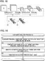
- Fig. 10 is a flowchart showing a flow of a process S B4 for calculating a head-related transfer function F (hereinafter, "function calculation process”), the process being executed by the function calculator 48.
- the function calculation process S B4 is executed by being triggered by identification of an estimated three-dimensional shape Z A of the target ear performed by the image searcher 442.
- the function calculator 48 identifies an estimated three-dimensional shape Z B of the left ear of the subject from the estimated three-dimensional shape Z A of the target ear (right ear) identified by the image searcher 442 (S B41 ), as shown in Fig. 11 . Specifically, the function calculator 48 identifies, as the estimated three-dimensional shape Z B of the left ear, an ear shape that has a symmetrical relation to the estimated three-dimensional shape Z A represented by the three-dimensional shape data D Z of the target ear. Then, as shown in Fig.
- the function calculator 48 joins the estimated three-dimensional shapes Z A and Z B to a head shape Z H , and thereby identifies a shape Z of the entire head including the head and the ears (S B42 ) (hereinafter, "target shape").
- the head shape Z H is a shape of a specific dummy head, or an average shape of heads of a large number of unspecified human beings.
- the function calculator 48 calculates head-related transfer functions F by carrying out acoustic analysis on the target shape Z (S B43 ). Specifically, the function calculator 48 of the first embodiment calculates, for each of the right ear and the left ear, a plurality of head-related transfer functions corresponding to different directions (different azimuth angles and different elevation angles) in which a sound arrives at the target shape Z.
- a known analysis method such as a boundary element method and a finite element method, may be used to calculate head-related transfer functions F. For example, techniques, such as that disclosed in Katz, Brian FG. "Boundary element method calculation of individual head-related transfer function. I. Rigid model calculation.” The Journal of the Acoustical Society of America 110.5 (2001): 2440-2448 , may be used to calculate head-related transfer functions F corresponding to the target shape Z.
- Fig. 12 is a flowchart showing a flow of a process S B for generating a head-related transfer function F (hereinafter, "ear shape analysis process”), the process being executed by the ear shape analyzer 40 of the first embodiment.
- the ear shape analysis process S B in Fig. 12 is executed when, for example, an instruction is given by the user to generate a head-related transfer function F after the ear shape model generator 30 has generated the ear shape model E.
- the ear shape data generator 42 Upon start of the ear shape analysis process S B , the ear shape data generator 42 generates the ear shape data v (1) to v (K) of the K candidate ears, using the ear shape model E, and the K principal component weight vectors w (1) to w (K) (S B1 ) differing from each other.
- the image generator 441 uses the point group P R of the reference ear and the sets of ear shape data v (k) of the candidate ears generated by the ear shape data generator 42 to generate, for each k-th candidate ear of the K candidate ears, three-dimensional shape data D C(k) of a candidate ear image G C(k) (one among the candidate ear images G C(1) to G C(K) ) representing a corresponding candidate ear (S B2 ). Then, the image searcher 442 identifies, as the estimated three-dimensional shape Z A of the target ear, an ear shape of a candidate ear image G C(k) having the smallest difference ⁇ (k) from the target ear image G U represented by the image data D G (S B3 ).
- the function calculator 48 calculates head-related transfer functions F for the target shape Z of the entire head, the target shape Z including the estimated three-dimensional shape Z A identified by the image searcher 442.
- head-related transfer functions F each reflecting an ear shape peculiar to the subject are generated, and the head-related transfer functions F are stored in the storage device 24.
- the audio processor 50 in Fig. 1 convolves the head-related transfer function F generated by the ear shape analyzer 40 into the audio signal X A , to generate the audio signal X B .
- Fig. 13 is a block diagram showing a configuration of the audio processor 50. As shown in Fig. 13 , the audio processor 50 of the first embodiment includes a sound field controller 52 and convolution calculators 54 R and 54 L .
- the user can instruct to the audio processing device 100 sound field conditions including a sound source location and a listening location in a virtual acoustic space.
- the sound field controller 52 calculates a direction in which a sound arrives to the listening location in the acoustic space. From among the multiple head-related transfer functions F calculated by the ear shape analyzer 40 and stored in the storage device 24, the sound field controller 52 selects for the respective ones of the left and right ears a head-related transfer function F corresponding to the direction in which the sound arrives at the listening location.
- the convolution calculator 54 R By convolving into the audio signal X A the head-related transfer function F of the right ear selected by the sound field controller 52, the convolution calculator 54 R generates an audio signal X B_R for a right channel. By convolving into the audio signal X A the head-related transfer function F of the left ear selected by the sound field controller 52, the convolution calculator 54 L generates an audio signal X B_L for a left channel. Convolution of the head-related transfer function F in a time domain (head-related impulse response) may be replaced by multiplication in a frequency domain.
- the shape of the candidate ear represented by the candidate ear image G C(k) found in the search is identified as the estimated three-dimensional shape Z A of the target ear. Accordingly, a probability of misestimating an ear shape can be reduced, compared to a configuration in which the shape of a target ear is estimated by deforming (morphing) a given shape.
- a head-related transfer function F that corresponds to the estimated three-dimensional shape Z A identified by the image searcher 442 is calculated. Consequently, an advantage is obtained in that it is possible to identify a head-related transfer function F, the use of which enables the subject to perceive an appropriate location of the sound image.
- a candidate ear image G C (k) of a candidate ear observed from a viewpoint conforming to a condition approximate to the imaging condition of the target ear image G U is generated. Accordingly, an advantage is obtained in that a candidate ear having a shape that approximates to the shape of the target ear can be appropriately selected, compared to a case where observation conditions for a candidate ear image G C(k) do not match those used when the target ear image G U was captured.
- the ear shape model E used in estimating the shape of the target ear reflects statistical tendencies of three-dimensional shapes of multiple sample ears.
- an advantage is obtained in that a three-dimensional shape of the target ear (estimated three-dimensional shape Z A ) can be estimated with high precision.
- an ear shape model E that includes not only a transformation matrix W but also a mean vector ⁇ is generated, and therefore, a candidate ear image G C(k) can be generated appropriately using the ear shape model E.
- the point groups P S(n) of the sample ears and the point group P R of the reference ear are identified from respective three-dimensional shape data D 0 representing three-dimensional shapes of the sample ears and the reference ear, and therefore, there is obtained an additional advantage in that these already available three-dimensional shape data D 0 (such as polygon mesh data) can be used to generate an ear shape model E.
- a translation vector ⁇ is calculated for every point p R of the point group P R of the reference ear, in relation to each corresponding point ps of a sample ear.
- a translation vector ⁇ is calculated for each of m A points p R constituting a part (hereinafter, "first group") of the point group P R of the reference ear, in relation to each corresponding point p S of a sample ear.
- ear shape data v (n) of a sample ear in the second embodiment includes m A translation vectors ⁇ corresponding to the respective points p R constituting the first group of the point group P R of the reference ear.
- Fig. 14 is a flowchart showing a flow of an operation of an ear shape data generator 42 of the second embodiment.
- Fig. 15 is a diagram explaining an operation of the ear shape data generator 42. The process in Fig. 14 is executed in step S B1 of the ear shape analysis process S B shown in Fig. 12 .
- the ear shape data generator 42 applies a principal component weight vector w (k) of a candidate ear to an ear shape model E, and thereby generates ear shape data v (k) of the candidate ear (S B11 ).
- the ear shape model E (a transformation matrix W and a mean vector ⁇ ) is generated by executing an ear shape model generation process S A that employs ear shape data v (n) of a sample ear including m A translation vectors ⁇ corresponding to the respective points p R constituting the first group of the point group P R of the reference ear, as described above.
- ear shape data v (k) of a candidate ear generated by applying a principal component weight vector w (k) to the ear shape model E is constituted by the m A translation vectors ⁇ corresponding to the respective points p R constituting the first group of the point group P R of the reference ear, as shown in Fig. 15 .
- translation vectors ⁇ of points p R constituting a group other than the first group are not generated by the process of applying a principal component weight vector w (k) to the ear shape model E, and are not included in ear shape data v (K) of a candidate ear.
- the ear shape data generator 42 of the second embodiment generates m B translation vectors ⁇ corresponding to the respective points p R constituting the second group of the point group P R of the reference ear by interpolation using the m A translation vectors ⁇ included in the ear shape data v (k) of a candidate ear (S B12 ).
- the sign "e” is a base of a natural logarithm
- the sign " ⁇ ” is a prescribed constant (positive number).
- the sign d (q) stands for a distance between a point p R(q) in the first group and the specific point p R (for example, a Euclidean distance).
- a weighted sum of the Q translation vectors ⁇ (1) to ⁇ (Q) which is calculated by using weighted values corresponding to respective distances d (q) between the specific point p R and the respective points p R(q) , is obtained as the translation vector ⁇ of the specific point p R .
- a translation vector ⁇ is calculated for all (m A + m B ) points p R of the reference ear.
- the number Q of points p R(q) in the first group that are taken into account in calculating the translation vector ⁇ of the specific point p R is typically set to a numerical value that is lower than the number m A of the points p R constituting the first group.
- the number Q of points p R(q) may be set to a numerical value corresponding to the number m A (that is, the translation vector ⁇ of the specific point p R may be calculated by interpolation of translation vectors ⁇ of all points p R belonging to the first group).
- step S B21 of the image generation process S B2 in Fig. 9 the ear shape data generator 42 translates the coordinates of each of m A points p R of the first group in the point group P R of the reference ear, by using a corresponding one of m A translation vectors ⁇ of the ear shape data v (k) of the candidate ear.
- the ear shape data generator 42 translates coordinates of each of the m B points p R constituting the second group of the point group P R of the reference ear, using a corresponding one of the m B translation vectors ⁇ having been obtained by the interpolation according to equation (6) (specifically, the translation vector ⁇ obtained by the interpolation is added to the coordinates of each point p R ). In this way, the ear shape data generator 42 generates three-dimensional shape data D C(k) of a candidate ear. The rest of the operation is substantially the same as that of the first embodiment.
- translation vectors ⁇ corresponding to the respective points p R constituting the second group of the point group P R of the reference ear are generated by interpolation of Q translation vectors ⁇ (1) to ⁇ (Q) included in ear shape data v (k) of a candidate ear.
- an advantage is obtained in that a load is reduced in a process executed by the ear shape data generator 42 to generate ear shape data v (k) of a candidate ear by applying a principal component weight vector w (k) to an ear shape model E, or in a process executed by the ear shape model generator 30 to generate an ear shape model E.
- the statistics processor 36 generates a transformation matrix W with M rows and M columns.
- a statistics processor 36 of the third embodiment removes (a) prescribed row(s) from the lower rows of the transformation matrix W with M rows and M columns (that is, (a) prescribed row(s) corresponding to small eigenvalues), the transformation matrix W having been generated by performing principal component analysis on N ear shape data v (1) to v (N) , and generates an ear shape model E including a transformation matrix W' that has been obtained by the removal and has M' rows and M columns (here, M' ⁇ M).
- the statistical processor 36 deletes (M - M') rows from the (M' + 1) th row to the Mth row in the matrix with M rows and M columns generated by the principal component analysis, and thereby obtains the transformation matrix W' with M' rows and M columns. Elements of rows from the first row to the M'th row are the same between the transformation matrix W and the transformation matrix W'.
- An ear shape data generator 42 of the third embodiment generates ear shape data v (1) to v (k) of K candidate ears using the transformation matrix W' of the ear shape model E. Specifically, the ear shape data generator 42 generates a transformation matrix W with M rows and M columns by adding (M minus M') rows to the transformation matrix W' (elements of the (M minus M') rows having a prescribed value (e.g., zero)), and generates ear shape data v (k) of a candidate ear by calculation of equation (5) using the transformation matrix W obtained by the addition.
- a transformation matrix W' is generated for the ear shape model E, which transformation matrix W' is obtained by removing (a) prescribed row(s) from the lower rows of the transformation matrix W with M rows and M columns, the transformation matrix W having been generated by performing principal component analysis on N ear shape data v (1) to v (N) of sample ears.
- a data amount of the ear shape model E can be reduced.
- the configuration of the second embodiment may be applied in the third embodiment.
- Fig. 16 is a block diagram showing a configuration of an audio processing system 200 according to a fourth embodiment.
- the audio processing system 200 of the fourth embodiment is a computer system including a terminal device 62 and an analysis processing device 64.
- the terminal device 62 is an information processing device, such as a portable telephone, a smartphone, a tablet terminal, and a personal computer; and the analysis processing device 64 is, for example, a server device, such as a web server.
- the audio processing system 200 includes multiple ones of the terminal device 62, but for the sake of convenience, the description below focuses on a freely selected, single terminal device 62.
- the terminal device 62 includes an audio processor 50, a sound output device 14, and a communication device 72 (communicator).
- the audio processor 50 convolves a head-related transfer function F into an audio signal X A in order to generate an audio signal X B
- the sound output device 14 outputs a sound that is in accordance with the audio signal X B generated by the audio processor 50.
- the communication device 72 communicates with the analysis processing device 64 via a communication network 16, such as a mobile communication network and the Internet. For example, the communication device 72 transmits to the analysis processing device 64 a distribution request Y for a head-related transfer function F.
- the distribution request Y includes image data D G of a target ear image Gu captured of a target ear of the user (subject) of the terminal device 62.
- the distribution request Y includes sound field conditions designating a sound source location and a listening location in an acoustic space.
- the analysis processing device 64 includes an ear shape model generator 30, an ear shape analyzer 40, a storage device 24, and a communication device 74.
- the communication device 74 communicates with the terminal device 62 via the communication network 16. For example, the communication device 74 receives the distribution request Y transmitted from the terminal device 62.
- the storage device 24 stores multiple sets of three-dimensional shape data D 0 that are substantially the same as those in the first embodiment.
- the ear shape model generator 30 generates an ear shape model E by executing the ear shape model generation process S A ( Fig. 6 ) using multiple three-dimensional shape data D 0 .
- the ear shape analyzer 40 executes the ear shape analysis process S B ( Fig. 12 ) using the ear shape model E generated by the ear shape model generator 30 and the image data D G received by the communication device 74 from the terminal device 62, thereby generating head-related transfer functions F corresponding to the sound field conditions designated by the distribution request Y.
- the communication device 74 transmits the head-related transfer functions F generated by the ear shape analyzer 40 to the terminal device 62 that has transmitted the distribution request Y.
- the head-related transfer functions F for the left and right ears which correspond to the sound field conditions designated by the distribution request Y, are transmitted from the analysis processing device 64 to the terminal device 62.
- the communication device 72 of the terminal device 62 receives the head-related transfer functions F transmitted from the analysis processing device 64.
- the audio processing device 100 convolves each of the head-related transfer functions F received by the communication device 72 into the audio signal X A so as to generate the audio signal X B .
- the user (subject) of the terminal device 62 is enabled to perceive a location of a sound image of a sound that is played by the sound output device 14.
- Fig. 17 is a block diagram showing a configuration of an ear shape analyzer 40 according to a fifth embodiment.
- the ear shape analyzer 40 of the fifth embodiment includes an estimation processor 46, an ear shape data generator 42, an ear shape identifier 44, and a function calculator 48.
- image data D G representing a target ear image G U , an ear shape model E (a transformation matrix W and a mean vector ⁇ ), and three-dimensional shape data D 0 of the reference ear are stored in a storage device 24.
- the image data D G in the first embodiment represents multiple target ear images G U in which the same target ear is captured from different angles.
- the estimation processor 46 applies the target ear image G U represented by the image data D G to a neural network v, so as to generate a principal component weight vector w of the target ear.
- the neural network v is a mathematical model indicating a relation between ear images and principal component weight vectors w, and is generated by machine learning using a large amount of learning data including ear images of sample ears and principal component weight vectors of the sample ears.
- Fig. 18 is a diagram explaining a neural network v used by the estimation processor 46.
- Multiple feature maps ⁇ 1 are generated by performing an arithmetic processing operation C 1 on multiple ear images G of an ear that have been captured from different angles.
- the arithmetic processing operation C 1 is expressed by equation (7a) below.
- the sign "Conv(G,K 1 )" in expression (7a) stands for calculation of convolving a convolution kernel K 1 into each of the multiple ear images G and adding up the results of convolution.
- the sign "b 1 " is a vector indicative of a compensation term (bias), and the sign "tanh” is a hyperbolic tangent function.
- the sign "Pool" in equation (7a) is a maximum pooling function for reducing the image subject to the arithmetic processing by selecting the maximum value of a plurality of pixel values in each of rectangular areas obtained by dividing the image subject to the arithmetic processing.
- ⁇ 1 Pool tanh Conv G , K 1 + b 1
- An arithmetic processing operation C 2 is carried out on the multiple feature maps ⁇ 1 having been generated in the arithmetic processing operation C 1 , and multiple feature maps ⁇ 2 are generated as a result.
- the arithmetic processing operation C 2 is expressed by equation (7b) below.
- the sign "Conv( ⁇ 1 ,K 2 )" in expression (7b) stands for calculation of convolving a convolution kernel K 2 into each of the multiple feature map ⁇ 1 and adding up the results of convolution.
- the sign "b 2 " is a vector indicative of a compensation term.
- An arithmetic processing operation C 4 is carried out on the connection vectors ⁇ 3 having been generated in the arithmetic processing operation C 3 , and a principal component weight vector v is generated as a result.
- the arithmetic processing operation C 4 is expressed by equation (7d) below.
- the variables (b 1 , b 2 , b 3 , K 1 , K 2 , ⁇ 3 , and ⁇ 4 ) used in the processing operations above define the neural network v.
- numerical values of the variables defining the neural network v are set using machine learning and are stored in the storage device 24.
- the estimation processor 46 of the fifth embodiment carries out, on the target ear image G U , the arithmetic processing operations C 1 to C 4 in which the numerical values stored in the storage device 24 are used, to thereby generate a principal component weight vector v of the target ear. Generation of the neural network v by machine learning will be described later.
- the ear shape data generator 42 in Fig. 17 applies to the ear shape model E the principal component weight vector w of the target ear generated by the estimation processor 46, and thereby generates ear shape data v of the target ear.
- the ear shape data generator 42 multiplies the principal component weight vector w estimated by the estimation processor 46 by an inverse matrix W -1 of the transformation matrix W and adds to the resultant a mean vector ⁇ , thereby calculating ear shape data v of the target ear.
- the ear shape data v of the target ear is an M-dimensional vector indicating a difference between the point group P R of the reference ear and a point group representing a three-dimensional shape of the target ear.
- the ear shape identifier 44 identifies an estimated three-dimensional shape Z A of the target ear from the ear shape data v generated by the ear shape data generator 42. Specifically, in accordance with the ear shape data v of the target ear, the ear shape identifier 44 moves points p R of the point group P R specified by the three-dimensional shape data D 0 of the reference ear, and thereby identifies three-dimensional shape data D Z representing the three-dimensional shape of the target ear. That is, for each point of the m A points p R of the point group P R of the reference ear, the translation vector ⁇ corresponding to that point in the ear shape data v of the target ear is added to the coordinates of that point. In this way, three-dimensional shape data D Z of the target ear is generated.
- the function calculator 48 in Fig. 17 calculates a head-related transfer function F of the subject, which corresponds to the estimated three-dimensional shape Z A of the target ear identified by the ear shape identifier 44.
- a method of calculating a head-related transfer function F from the estimated three-dimensional shape Z A , and a method of generating an audio signal X B from an audio signal X A using a head-related transfer function F are substantially the same as those of the first embodiment.
- Fig. 19 is a flowchart showing a flow of an ear shape analysis process S C executed by the ear shape analyzer 40 of the fifth embodiment to generate a head-related transfer function F.
- the ear shape analysis process S C in Fig. 19 is executed when, for example, an instruction is given by the user to generate a head-related transfer function F.
- the estimation processor 46 Upon start of the ear shape analysis process S C , the estimation processor 46 applies the target ear image G U represented by the image data D G to the neural network v, and thereby generates a principal component weight vector w of the target ear (S C1 ).
- the ear shape data generator 42 applies the principal component weight vector w of the target ear generated by the estimation processor 46 to the ear shape model E, and thereby generates ear shape data v of the target ear (S C2 ).
- the ear shape identifier 44 identifies an estimated three-dimensional shape Z A of the target ear from the ear shape data v generated by the ear shape data generator 42 (S C3 ).
- the function calculator 48 calculates head-related transfer functions F for a target shape Z of the entire head (S B4 ), the target shape Z including the estimated three-dimensional shape Z A of the target ear identified by the ear shape identifier 44.
- ear shape data v of the target ear is generated by applying a principal component weight vector w to an ear shape model E, and an estimated three-dimensional shape Z A of the target ear is identified from the ear shape data v. Accordingly, in substantially the same way as in the first embodiment, a probability of misestimating an ear shape can be reduced, compared to a configuration in which the shape of a target ear is estimated by deforming (morphing) a given shape.
- the ear shape of the candidate ear for which the difference ⁇ (k) between the target ear image G U and each of the K candidate ear images G C(k) respectively corresponding to the K candidate ears is the smallest, is searched for as the estimated three-dimensional shape Z A of the target ear.
- generation of a candidate ear image G C(k) image generation process Sb 2
- comparison of a candidate ear image G C(k) with the target ear image G U (calculation of a difference ⁇ (k) ) be performed repeatedly for K candidate ears.
- ear shape data v of the target ear is generated by applying, to the ear shape model E, a principal component weight vector w of the target ear identified from the target ear image G U .
- a candidate ear image G C(k) and comparison of a candidate ear image G C(k) with the target ear image G U are no need to repeat generation of a candidate ear image G C(k) and comparison of a candidate ear image G C(k) with the target ear image G U .
- an advantage is obtained in the fifth embodiment in that an amount of calculation necessary for the ear shape analyzer 40 to identify an estimated three-dimensional shape Z A of the target ear is reduced, compared to the first embodiment.
- the neural network v may include a process to normalize (hereinafter, "normalization process") the principal component weight vector w of the target ear generated in the process of step S C1 mentioned above. That is, a normalization layer may be added to the uppermost layer of the neural network v.
- the normalization process serves to divide each of M elements constituting the principal component weight vector w by a standard deviation of the M elements.
- the principal component weight vector w having undergone the normalization process (that is, a principal component weight vector w generated by the neural network v) is applied to the ear shape model E as in the example given above (S C2 ).
- an advantage is obtained in that, as a result of executing the normalization process described above, a probability of estimating an excessively anomalous principal component weight vector w (and in turn an excessively anomalous estimated three-dimensional shape Z A of the target ear) can be reduced.
- Fig. 20 is a block diagram showing a configuration of an ear shape model generator 30 of the fifth embodiment.
- the ear shape model generator 30 of the fifth embodiment includes a learning processor 38 in addition to elements for generating an ear shape model E (a point group identifier 32, a sample ear analyzer 34, and a statistics processor 36) that are substantially the same as those in the first embodiment.
- the learning processor 38 determines numerical values for the variables of the neural network v that are used by the estimation processor 46 to generate the principal component weight vector w.
- Each learning data D T includes an ear image G of a sample ear and an already-known principal component weight vector w of that ear image G.
- the learning processor 38 determines numerical values for the variables (b 1 , b 2 , b 3 , K 1 , K 2 , ⁇ 3 , and ⁇ 4 ) defining the neural network v such that, according to these numerical values, a vector calculated by applying an ear image G of a sample ear to the neural network v approximates to the already known principal component weight vector w of that ear image G.
- the numerical values of the variables determined by the learning processor 38 are stored in the storage device 24 and, as described above, used in generation of a principal component weight vector w (arithmetic processing operations C 1 to C 4 ) by the estimation processor 46.
- the learning processor 38 determines the numerical value of each variable of the neural network v so that the error function ⁇ defined by equation (8) below is minimized.
- ⁇
- 2 " in equation (8) stands for a 2-norm (Euclidean norm).
- the sign "w_est” is a principal component weight vector w calculated by applying an ear image G of a sample ear to the neural network v
- the sign "w_truth” is a principal component weight vector w (correct solution) included in the learning data D T .
- numerical values of the variables of the neural network v are determined such that a difference is minimized between the principal component weight vector w_est calculated by the neural network v from the ear image G in the learning data D T and the principal component weight vector w_truth included in the learning data D T .
- ⁇ _reg ⁇ 1 mean w _ est * * 2 ⁇ 2 2 + ⁇ 3 mean w _ est ⁇ ⁇ 4 2
- Equation (9) stands for a mean of multiple elements of a vector x
- sign "x**2" stands for a vector obtained by squaring each element of the vector x.
- the signs " ⁇ 1 " to " ⁇ 4 " are prescribed real numbers.
- a configuration substantially the same as that of the second embodiment may be employed in the fifth embodiment.
- translation vectors ⁇ corresponding to the respective points p R constituting the second group of the point group P R of the reference ear may be generated by interpolation of Q translation vectors ⁇ (1) to ⁇ (Q) included in the ear shape data v (k) of the target ear generated by the ear shape data generator 42.
- the fifth embodiment may employ the configuration of the third embodiment in which a transformation matrix W' is generated as an ear shape model E, the transformation matrix W' being obtained by removing (a) prescribed row(s) from the lower rows of the transformation matrix W with M rows and M columns.
- the fifth embodiment may also employ the configuration of the fourth embodiment.
- an estimated three-dimensional shape Z A of the target ear is identified using the configuration and the processes of the fifth embodiment, and head-related transfer functions F corresponding to a target shape Z including the estimated three-dimensional shape Z A are distributed to the terminal device 62.
- An ear shape analysis method is implemented by a computer and the method includes: generating an ear shape data set by applying a principal component weight vector to an ear shape model, the ear shape model indicating a relation between ear shape data sets and principal component weight vectors, each ear shape data set indicating a difference between a point group representing a three-dimensional shape of an ear and a point group representing a three-dimensional shape of a reference ear, and each principal component weight vector indicating weights of principal components of the corresponding ear shape data set; and identifying from the generated ear shape data set generated by an ear shape data generator an estimated three-dimensional shape of a target ear corresponding to a target ear image represented by image data.
- an estimated three-dimensional shape of the target ear is identified from ear shape data generated by applying a principal component weight vector to an ear shape model indicating a relation between ear shape data sets and principal component weight vectors. Accordingly, a probability of misestimating an ear shape can be reduced, compared to a configuration in which the three-dimensional shape of a target ear is estimated by deforming (morphing) a given shape.
- the generated ear shape data set is one of a plurality of ear shape data sets, each corresponding to one of a plurality of candidate ears
- the generating the ear shape data set includes applying to the ear shape model each of a plurality of principal component weight vectors including the principal component weight vector, to generate each of the plurality of ear shape data sets
- the identifying the estimated three-dimensional shape includes, generating for the plurality of candidate ears a plurality of candidate ear images, each representing a corresponding candidate ear in accordance with the point group representing the three-dimensional shape of the reference ear and the ear shape data set of the candidate ear, and comparing the target ear image represented by the image data with each of the plurality of candidate ear images generated for the plurality of candidate ears, to identify as the estimated three-dimensional shape of the target ear an ear shape that corresponds to a candidate ear corresponding to a candidate ear image that has the smallest difference among differences existing between the target ear
- the target ear image and each of the plurality of candidate ear images generated using the ear shape model are compared with each other, and an ear shape that corresponds to a candidate ear of a candidate ear image having the smallest difference from the target ear image is identified as an estimated three-dimensional shape of the target ear. Accordingly, an advantage is obtained in that an estimated three-dimensional shape of the target ear can be identified by use of a simple image comparison process.
- the generating each candidate ear image includes generating a candidate ear image of each candidate ear observed from a viewpoint conforming to conditions close to conditions used when the target ear represented by the image data was captured.
- the third mode there is generated a candidate ear image that represents a candidate ear viewed from a direction close to a direction when the target ear was captured as the target ear image. Accordingly, an advantage is obtained in that an appropriate candidate ear having a three-dimensional shape close to that of the target ear can be selected; in contrast to a case where observation conditions for a candidate ear corresponding to a candidate ear image do not match those used when the target ear image was captured.
- the generating the ear shape data set includes, applying each of the principal component weight vectors to the ear shape model, to generate the ear shape data set of each candidate ear, the ear shape data set including a plurality of translation vectors corresponding to respective points constituting a first group that is a part of the point group of the reference ear, and by interpolation of the plurality of translation vectors included in the ear shape data set of each candidate ear, generating translation vectors corresponding to respective points constituting a second group of the point group of the reference ear, the second group being constituted by all points of the point group of the reference ear other than the points constituting the first group, and the generating each candidate ear image includes generating each candidate ear image by moving each of the points constituting the first group of the point group of the reference ear in accordance with a corresponding one of the plurality of translation vectors of the ear shape data set of the candidate ear, and by moving each of the points
- translation vectors corresponding to the points constituting the second group of the point group of the reference ear are generated by interpolation of a plurality of translation vectors included in ear shape data of a candidate ear, and therefore, there is no need to generate translation vectors for the entirety of the point group of the reference ear using the ear shape model. Accordingly, an advantage is obtained in that a load is reduced in a process of generating ear shape data of a candidate ear by applying a principal component weight vector to an ear shape model, or in a process of generating an ear shape model.
- the ear shape analysis method further includes generating a principal component weight vector by applying the target ear image represented by the image data to a neural network indicating a relation between ear images and principal component weight vectors, and the generating the ear shape data set includes generating an ear shape data set of the target ear by applying the principal component weight vector generated by the neural network to the ear shape model, and the identifying the estimated three-dimensional shape includes identifying the estimated three-dimensional shape of the target ear in accordance with the point group representing the three-dimensional shape of the reference ear and the ear shape data set of the target ear.
- a principal component weight vector generated by applying the target ear image to a neural network is applied to the ear shape model, and accordingly, there is no need to repeat generation of a candidate ear image and comparison of a candidate ear image with the target ear image.
- an advantage is obtained in that an amount of calculation necessary for identifying an estimated three-dimensional shape of the target ear is reduced, compared to the second mode in which generation of a candidate ear image and comparison of a candidate ear image with the target ear image are repeated multiple times.
- the ear shape analysis method further includes calculating a head-related transfer function corresponding to the estimated three-dimensional shape.
- a probability of misestimating an ear shape is reduced as described above, and therefore, an advantage is obtained in that it is possible to identify head-related transfer functions F, the use of which enables a listener with the target ear to perceive an appropriate location of the sound image.
- the ear shape analysis method further includes receiving the image data from a terminal device, and transmitting to the terminal device the head-related transfer function calculated from the image data.
- the seventh mode an estimated three-dimensional shape of the target ear is identified from the image data received from the terminal device, and a head-related transfer function corresponding to the estimated three-dimensional shape is transmitted to the terminal device. Accordingly, an advantage is obtained in that there is no need to perform at a terminal device identification of an estimated three-dimensional shape of the target ear or calculation of a head-related transfer function for the estimated three-dimensional shape.
- An ear shape analysis device includes: an ear shape data generator configured to generate an ear shape data set by applying a principal component weight vector to an ear shape model, the ear shape model indicating a relation between ear shape data sets and principal component weight vectors, each ear shape data set indicating a difference between a point group representing a three-dimensional shape of an ear and a point group representing a three-dimensional shape of a reference ear, and each principal component weight vector indicating weights of principal components of the corresponding ear shape data set; and an ear shape identifier configured to identify, from the ear shape data set generated by the ear shape data generator, an estimated three-dimensional shape of a target ear corresponding to a target ear image represented by image data.
- an estimated three-dimensional shape of the target ear is identified from ear shape data generated by applying a principal component weight vector to an ear shape model indicating a relation between ear shape data sets and principal component weight vectors. Accordingly, a probability of misestimating an ear shape can be reduced, compared to a configuration in which the three-dimensional shape of a target ear is estimated by deforming a given shape.
- the generated ear shape data set is one of a plurality of ear shape data sets, each corresponding to one of a plurality of candidate ears
- the ear shape data generator applies to the ear shape model each of a plurality of principal component weight vectors including the principal component weight vector, to generate each of the ear shape data sets for the plurality of candidate ears
- the ear shape identifier includes, an image generator configured to generate for the plurality of candidate ears a plurality of candidate ear images, each representing a corresponding candidate ear, in accordance with the point group representing the three-dimensional shape of the reference ear and the ear shape data set of the candidate ear, and an image searcher configured to compare the target ear image represented by the image data with each of the plurality of candidate ear images generated for the plurality of candidate ears, to identify as the estimated three-dimensional shape of the target ear an ear shape that corresponds to a candidate ear corresponding to a candidate ear image that has the smallest difference
- the ear shape analysis device further includes an estimation processor configured to generate a principal component weight vector by applying the target ear image represented by the image data to a neural network indicating a relation between ear images and principal component weight vectors, and the ear shape data generator generates an ear shape data set of the target ear by applying the principal component weight vector generated by the neural network to the ear shape model, and the ear shape identifier identifies the estimated three-dimensional shape of the target ear in accordance with the point group representing the three-dimensional shape of the reference ear and the ear shape data set of the target ear.
- a principal component weight vector generated by applying the target ear image to a neural network is applied to the ear shape model, and therefore, there is no need to repeat generation of a candidate ear image and comparison of a candidate ear image with the target ear image. Accordingly, an advantage is obtained in that an amount of calculation necessary for identifying an estimated three-dimensional shape of the target ear is reduced; in contrast to the ninth mode in which generation of a candidate ear image and comparison of a candidate ear image with the target ear image are repeated multiple times.
- a preferred example, namely, the eleventh mode of the present invention is an ear shape model generation method implemented by a computer to generate an ear shape model used in generating a candidate ear image for comparison with a target ear image represented by image data, the method including: generating, for a plurality of sample ears, a plurality of ear shape data sets, each indicating a difference between a point group representing a three-dimensional shape of a corresponding sample ear and a point group representing a three-dimensional shape of a reference ear, and calculating a transformation matrix for translating ear shape data into a principal component weight vector indicating weights of principal components, by performing principal component analysis on the plurality of generated ear shape data sets, to generate the ear shape model including the transformation matrix or an inverse matrix of the transformation matrix.
- the ear shape model used in estimating the three-dimensional shape of the target ear reflects statistical tendencies of three-dimensional shapes of a plurality of sample ears. Accordingly, an advantage is obtained in that the three-dimensional shape of the target ear can be estimated with high precision.
- the generating the ear shape model includes calculating, for the plurality of sample ears, a mean vector of the ear shape data sets, and generating the ear shape model including the mean vector.
- the twelfth mode there is generated an ear shape model that includes a mean vector of a plurality of ear shape data sets in addition to the transformation matrix for translating ear shape data into a principal component weight vector, or the inverse matrix of the transformation matrix. Accordingly, an advantage is obtained in that an appropriate candidate ear image can be generated using this ear shape model.
- the generating the ear shape model includes removing prescribed rows from lower rows of the transformation matrix calculated by the principal component analysis, and generating the ear shape model indicating a transformation matrix resulting from the removing of the prescribed rows.
- a prescribed row is removed from the lower rows of the transformation matrix calculated by the principal component analysis, and accordingly an amount of data of the ear shape model can be reduced.
Landscapes
- Health & Medical Sciences (AREA)
- Engineering & Computer Science (AREA)
- Life Sciences & Earth Sciences (AREA)
- Physics & Mathematics (AREA)
- General Physics & Mathematics (AREA)
- Animal Behavior & Ethology (AREA)
- Public Health (AREA)
- Veterinary Medicine (AREA)
- General Health & Medical Sciences (AREA)
- Biophysics (AREA)
- Pathology (AREA)
- Biomedical Technology (AREA)
- Heart & Thoracic Surgery (AREA)
- Medical Informatics (AREA)
- Molecular Biology (AREA)
- Surgery (AREA)
- Theoretical Computer Science (AREA)
- Dentistry (AREA)
- Oral & Maxillofacial Surgery (AREA)
- Software Systems (AREA)
- Computer Vision & Pattern Recognition (AREA)
- Geometry (AREA)
- Computer Graphics (AREA)
- Architecture (AREA)
- General Engineering & Computer Science (AREA)
- Computer Hardware Design (AREA)
- Multimedia (AREA)
- Image Processing (AREA)
- Image Analysis (AREA)
- Length Measuring Devices By Optical Means (AREA)
- Measurement Of The Respiration, Hearing Ability, Form, And Blood Characteristics Of Living Organisms (AREA)
- Image Generation (AREA)
Applications Claiming Priority (2)
| Application Number | Priority Date | Filing Date | Title |
|---|---|---|---|
| JP2015180993 | 2015-09-14 | ||
| PCT/JP2016/073829 WO2017047309A1 (fr) | 2015-09-14 | 2016-08-15 | Procédé d'analyse de forme d'oreille, dispositif d'analyse de forme d'oreille, et procédé de génération de modèle de forme d'oreille |
Publications (3)
| Publication Number | Publication Date |
|---|---|
| EP3351172A1 true EP3351172A1 (fr) | 2018-07-25 |
| EP3351172A4 EP3351172A4 (fr) | 2019-04-17 |
| EP3351172B1 EP3351172B1 (fr) | 2021-05-19 |
Family
ID=58288958
Family Applications (1)
| Application Number | Title | Priority Date | Filing Date |
|---|---|---|---|
| EP16846180.4A Active EP3351172B1 (fr) | 2015-09-14 | 2016-08-15 | Procédé d'analyse de forme d'oreille, dispositif d'analyse de forme d'oreille, et procédé de génération de modèle de forme d'oreille |
Country Status (5)
| Country | Link |
|---|---|
| US (1) | US10607358B2 (fr) |
| EP (1) | EP3351172B1 (fr) |
| JP (1) | JP6687032B2 (fr) |
| CN (1) | CN108024762B (fr) |
| WO (1) | WO2017047309A1 (fr) |
Cited By (2)
| Publication number | Priority date | Publication date | Assignee | Title |
|---|---|---|---|---|
| DE202019000718U1 (de) | 2019-02-14 | 2019-02-26 | WERRTA GmbH Düsen- und Zerstäubungstechnik | Inhalator |
| CN113039816A (zh) * | 2018-10-10 | 2021-06-25 | 索尼集团公司 | 信息处理装置、信息处理方法和信息处理程序 |
Families Citing this family (22)
| Publication number | Priority date | Publication date | Assignee | Title |
|---|---|---|---|---|
| FI20165211A (fi) | 2016-03-15 | 2017-09-16 | Ownsurround Ltd | Järjestely HRTF-suodattimien valmistamiseksi |
| FR3057981B1 (fr) * | 2016-10-24 | 2019-07-26 | Mimi Hearing Technologies GmbH | Procede d'elaboration d'un nuage de points 3d representatif d'une oreille 3d d'un individu, et systeme associe |
| US10701506B2 (en) | 2016-11-13 | 2020-06-30 | EmbodyVR, Inc. | Personalized head related transfer function (HRTF) based on video capture |
| JP2019536395A (ja) * | 2016-11-13 | 2019-12-12 | エンボディーヴィーアール、インコーポレイテッド | 耳介の画像を撮像し、耳介の画像を用いて人間の聴覚の解剖学的構造の特徴を示すためのシステムおよび方法 |
| WO2019094114A1 (fr) * | 2017-11-13 | 2019-05-16 | EmbodyVR, Inc. | Fonction de transfert asservie aux mouvements de la tête (hrtf) personnalisée sur la base de capture vidéo |
| CN107944117B (zh) * | 2017-11-17 | 2019-03-05 | 华中科技大学 | 一种基于流动特征获取注塑制品类型的方法 |
| AU2018377863B2 (en) * | 2017-12-01 | 2022-08-04 | Hearables 3D Pty Ltd | Customization method and apparatus |
| GB2569817B (en) * | 2017-12-29 | 2021-06-23 | Snugs Tech Ltd | Ear insert shape determination |
| FI20185300A1 (fi) | 2018-03-29 | 2019-09-30 | Ownsurround Ltd | Järjestely päähän liittyvien siirtofunktiosuodattimien muodostamiseksi |
| US10917735B2 (en) * | 2018-05-11 | 2021-02-09 | Facebook Technologies, Llc | Head-related transfer function personalization using simulation |
| CN108966083A (zh) * | 2018-08-09 | 2018-12-07 | 联想(北京)有限公司 | 一种控制方法及电子设备 |
| US11026039B2 (en) | 2018-08-13 | 2021-06-01 | Ownsurround Oy | Arrangement for distributing head related transfer function filters |
| KR102274581B1 (ko) * | 2018-10-16 | 2021-07-07 | 광주과학기술원 | 개인화된 hrtf 생성 방법 |
| JP7055762B2 (ja) * | 2019-03-05 | 2022-04-18 | アルパイン株式会社 | 顔特徴部検出装置、顔特徴部検出方法 |
| KR102249389B1 (ko) * | 2019-04-30 | 2021-05-07 | 전수진 | 아기 두상 성장 관리 시스템 |
| JP7358010B2 (ja) * | 2019-07-29 | 2023-10-10 | アルパイン株式会社 | 頭部伝達関数の推定モデル生成装置、頭部伝達関数の推定装置および頭部伝達関数の推定用プログラム |
| WO2021024747A1 (fr) | 2019-08-02 | 2021-02-11 | ソニー株式会社 | Dispositif de sortie audio, et système de sortie audio utilisant celui-ci |
| JP7344149B2 (ja) | 2020-02-07 | 2023-09-13 | キオクシア株式会社 | 最適化装置及び最適化方法 |
| US20230222687A1 (en) * | 2020-08-14 | 2023-07-13 | VisiSonics Corporation | Systems and methods for head related transfer function personalization |
| US11778408B2 (en) | 2021-01-26 | 2023-10-03 | EmbodyVR, Inc. | System and method to virtually mix and audition audio content for vehicles |
| CN114495171B (zh) * | 2022-01-28 | 2024-05-14 | 杭州师范大学 | 一种基于aam的耳像识别方法 |
| CN117291979B (zh) * | 2023-09-26 | 2024-04-26 | 北京鹰之眼智能健康科技有限公司 | 一种耳洞定位方法、电子设备及存储介质 |
Family Cites Families (11)
| Publication number | Priority date | Publication date | Assignee | Title |
|---|---|---|---|---|
| JP3521900B2 (ja) * | 2002-02-04 | 2004-04-26 | ヤマハ株式会社 | バーチャルスピーカアンプ |
| JPWO2005025270A1 (ja) * | 2003-09-08 | 2006-11-16 | 松下電器産業株式会社 | 音像制御装置の設計ツールおよび音像制御装置 |
| KR20070052296A (ko) * | 2004-09-08 | 2007-05-21 | 코닌클리케 필립스 일렉트로닉스 엔.브이. | 귀 자동인식을 위한 형상 추출 알고리즘 |
| JP2007299070A (ja) | 2006-04-27 | 2007-11-15 | Toshiba Corp | 顔形状モデル生成装置及びその方法 |
| CN101369309B (zh) * | 2008-09-26 | 2011-08-24 | 北京科技大学 | 基于主动表观模型和外耳长轴的人耳图像归一化方法 |
| WO2012028906A1 (fr) * | 2010-09-03 | 2012-03-08 | Sony Ericsson Mobile Communications Ab | Détermination de fonctions de transfert individualisées liées aux mouvements de la tête |
| JP5754595B2 (ja) * | 2011-11-22 | 2015-07-29 | 日本電信電話株式会社 | トランスオーラルシステム |
| US9030545B2 (en) * | 2011-12-30 | 2015-05-12 | GNR Resound A/S | Systems and methods for determining head related transfer functions |
| US20150073262A1 (en) * | 2012-04-02 | 2015-03-12 | Phonak Ag | Method for estimating the shape of an individual ear |
| CN102831390A (zh) * | 2012-07-02 | 2012-12-19 | 北京科技大学 | 一种人耳认证系统及方法 |
| FR3040807B1 (fr) * | 2015-09-07 | 2022-10-14 | 3D Sound Labs | Procede et systeme d'elaboration d'une fonction de transfert relative a la tete adaptee a un individu |
-
2016
- 2016-08-15 EP EP16846180.4A patent/EP3351172B1/fr active Active
- 2016-08-15 JP JP2017539786A patent/JP6687032B2/ja active Active
- 2016-08-15 CN CN201680052684.7A patent/CN108024762B/zh active Active
- 2016-08-15 WO PCT/JP2016/073829 patent/WO2017047309A1/fr active Application Filing
-
2018
- 2018-03-13 US US15/920,206 patent/US10607358B2/en active Active
Cited By (6)
| Publication number | Priority date | Publication date | Assignee | Title |
|---|---|---|---|---|
| CN113039816A (zh) * | 2018-10-10 | 2021-06-25 | 索尼集团公司 | 信息处理装置、信息处理方法和信息处理程序 |
| EP3866492A4 (fr) * | 2018-10-10 | 2021-12-08 | Sony Group Corporation | Dispositif, procédé et programme de traitement d'informations |
| US11595772B2 (en) | 2018-10-10 | 2023-02-28 | Sony Group Corporation | Information processing device, information processing method, and information processing program |
| CN113039816B (zh) * | 2018-10-10 | 2023-06-06 | 索尼集团公司 | 信息处理装置、信息处理方法和信息处理程序 |
| DE202019000718U1 (de) | 2019-02-14 | 2019-02-26 | WERRTA GmbH Düsen- und Zerstäubungstechnik | Inhalator |
| WO2020165356A1 (fr) | 2019-02-14 | 2020-08-20 | WERRTA GmbH Düsen- und Zerstäubungstechnik | Dispositif portable pour l'administration d'un liquide physiologiquement actif |
Also Published As
| Publication number | Publication date |
|---|---|
| US20180204341A1 (en) | 2018-07-19 |
| JPWO2017047309A1 (ja) | 2018-06-28 |
| JP6687032B2 (ja) | 2020-04-22 |
| CN108024762A (zh) | 2018-05-11 |
| US10607358B2 (en) | 2020-03-31 |
| EP3351172A4 (fr) | 2019-04-17 |
| WO2017047309A1 (fr) | 2017-03-23 |
| CN108024762B (zh) | 2020-09-22 |
| EP3351172B1 (fr) | 2021-05-19 |
Similar Documents
| Publication | Publication Date | Title |
|---|---|---|
| US10607358B2 (en) | Ear shape analysis method, ear shape analysis device, and ear shape model generation method | |
| US10313818B2 (en) | HRTF personalization based on anthropometric features | |
| US9681250B2 (en) | Statistical modelling, interpolation, measurement and anthropometry based prediction of head-related transfer functions | |
| Zotkin et al. | Regularized HRTF fitting using spherical harmonics | |
| US9906884B2 (en) | Methods, systems, and computer readable media for utilizing adaptive rectangular decomposition (ARD) to generate head-related transfer functions | |
| Geronazzo et al. | Do we need individual head-related transfer functions for vertical localization? The case study of a spectral notch distance metric | |
| WO2014147442A1 (fr) | Appareil audio spatial | |
| US10917735B2 (en) | Head-related transfer function personalization using simulation | |
| TWI699709B (zh) | 視線追蹤設備中確定參數的方法和裝置 | |
| CN109754464B (zh) | 用于生成信息的方法和装置 | |
| CN111524216A (zh) | 生成三维人脸数据的方法和装置 | |
| Grijalva et al. | Anthropometric-based customization of head-related transfer functions using Isomap in the horizontal plane | |
| CN114298997B (zh) | 一种伪造图片检测方法、装置及存储介质 | |
| US20180242080A1 (en) | Covariance matrix estimation with acoustic imaging | |
| US10390167B2 (en) | Ear shape analysis device and ear shape analysis method | |
| CN113038356A (zh) | 一种个性化hrtf快速建模获取方法 | |
| CN106874592B (zh) | 虚拟听觉重放方法及系统 | |
| Wang et al. | Prediction of head-related transfer function based on tensor completion | |
| Luo et al. | Gaussian process data fusion for heterogeneous HRTF datasets | |
| Zhao et al. | Efficient prediction of individual head-related transfer functions based on 3D meshes | |
| Grijalva et al. | A Virtual Listener For HRTF-Based Sound Source Localization Using Support Vector Regression | |
| US20240089689A1 (en) | Method for determining a personalized head-related transfer function | |
| CN113835065B (zh) | 基于深度学习的声源方向确定方法、装置、设备及介质 | |
| CN114141265A (zh) | 语音视频的降噪方法、装置、存储介质和设备 |
Legal Events
| Date | Code | Title | Description |
|---|---|---|---|
| STAA | Information on the status of an ep patent application or granted ep patent |
Free format text: STATUS: THE INTERNATIONAL PUBLICATION HAS BEEN MADE |
|
| PUAI | Public reference made under article 153(3) epc to a published international application that has entered the european phase |
Free format text: ORIGINAL CODE: 0009012 |
|
| STAA | Information on the status of an ep patent application or granted ep patent |
Free format text: STATUS: REQUEST FOR EXAMINATION WAS MADE |
|
| 17P | Request for examination filed |
Effective date: 20180413 |
|
| AK | Designated contracting states |
Kind code of ref document: A1 Designated state(s): AL AT BE BG CH CY CZ DE DK EE ES FI FR GB GR HR HU IE IS IT LI LT LU LV MC MK MT NL NO PL PT RO RS SE SI SK SM TR |
|
| AX | Request for extension of the european patent |
Extension state: BA ME |
|
| DAV | Request for validation of the european patent (deleted) | ||
| DAX | Request for extension of the european patent (deleted) | ||
| A4 | Supplementary search report drawn up and despatched |
Effective date: 20190314 |
|
| RIC1 | Information provided on ipc code assigned before grant |
Ipc: G06T 19/20 20110101ALI20190308BHEP Ipc: G06T 7/00 20170101ALI20190308BHEP Ipc: G01B 11/24 20060101ALI20190308BHEP Ipc: A61B 5/107 20060101AFI20190308BHEP |
|
| GRAP | Despatch of communication of intention to grant a patent |
Free format text: ORIGINAL CODE: EPIDOSNIGR1 |
|
| STAA | Information on the status of an ep patent application or granted ep patent |
Free format text: STATUS: GRANT OF PATENT IS INTENDED |
|
| INTG | Intention to grant announced |
Effective date: 20201214 |
|
| GRAS | Grant fee paid |
Free format text: ORIGINAL CODE: EPIDOSNIGR3 |
|
| GRAA | (expected) grant |
Free format text: ORIGINAL CODE: 0009210 |
|
| STAA | Information on the status of an ep patent application or granted ep patent |
Free format text: STATUS: THE PATENT HAS BEEN GRANTED |
|
| AK | Designated contracting states |
Kind code of ref document: B1 Designated state(s): AL AT BE BG CH CY CZ DE DK EE ES FI FR GB GR HR HU IE IS IT LI LT LU LV MC MK MT NL NO PL PT RO RS SE SI SK SM TR |
|
| REG | Reference to a national code |
Ref country code: GB Ref legal event code: FG4D |
|
| REG | Reference to a national code |
Ref country code: CH Ref legal event code: EP |
|
| REG | Reference to a national code |
Ref country code: DE Ref legal event code: R096 Ref document number: 602016058190 Country of ref document: DE |
|
| REG | Reference to a national code |
Ref country code: AT Ref legal event code: REF Ref document number: 1393197 Country of ref document: AT Kind code of ref document: T Effective date: 20210615 |
|
| REG | Reference to a national code |
Ref country code: IE Ref legal event code: FG4D |
|
| REG | Reference to a national code |
Ref country code: LT Ref legal event code: MG9D |
|
| REG | Reference to a national code |
Ref country code: AT Ref legal event code: MK05 Ref document number: 1393197 Country of ref document: AT Kind code of ref document: T Effective date: 20210519 |
|
| REG | Reference to a national code |
Ref country code: NL Ref legal event code: MP Effective date: 20210519 |
|
| PG25 | Lapsed in a contracting state [announced via postgrant information from national office to epo] |
Ref country code: FI Free format text: LAPSE BECAUSE OF FAILURE TO SUBMIT A TRANSLATION OF THE DESCRIPTION OR TO PAY THE FEE WITHIN THE PRESCRIBED TIME-LIMIT Effective date: 20210519 Ref country code: LT Free format text: LAPSE BECAUSE OF FAILURE TO SUBMIT A TRANSLATION OF THE DESCRIPTION OR TO PAY THE FEE WITHIN THE PRESCRIBED TIME-LIMIT Effective date: 20210519 Ref country code: HR Free format text: LAPSE BECAUSE OF FAILURE TO SUBMIT A TRANSLATION OF THE DESCRIPTION OR TO PAY THE FEE WITHIN THE PRESCRIBED TIME-LIMIT Effective date: 20210519 Ref country code: AT Free format text: LAPSE BECAUSE OF FAILURE TO SUBMIT A TRANSLATION OF THE DESCRIPTION OR TO PAY THE FEE WITHIN THE PRESCRIBED TIME-LIMIT Effective date: 20210519 Ref country code: BG Free format text: LAPSE BECAUSE OF FAILURE TO SUBMIT A TRANSLATION OF THE DESCRIPTION OR TO PAY THE FEE WITHIN THE PRESCRIBED TIME-LIMIT Effective date: 20210819 |
|
| PG25 | Lapsed in a contracting state [announced via postgrant information from national office to epo] |
Ref country code: NO Free format text: LAPSE BECAUSE OF FAILURE TO SUBMIT A TRANSLATION OF THE DESCRIPTION OR TO PAY THE FEE WITHIN THE PRESCRIBED TIME-LIMIT Effective date: 20210819 Ref country code: PL Free format text: LAPSE BECAUSE OF FAILURE TO SUBMIT A TRANSLATION OF THE DESCRIPTION OR TO PAY THE FEE WITHIN THE PRESCRIBED TIME-LIMIT Effective date: 20210519 Ref country code: PT Free format text: LAPSE BECAUSE OF FAILURE TO SUBMIT A TRANSLATION OF THE DESCRIPTION OR TO PAY THE FEE WITHIN THE PRESCRIBED TIME-LIMIT Effective date: 20210920 Ref country code: SE Free format text: LAPSE BECAUSE OF FAILURE TO SUBMIT A TRANSLATION OF THE DESCRIPTION OR TO PAY THE FEE WITHIN THE PRESCRIBED TIME-LIMIT Effective date: 20210519 Ref country code: RS Free format text: LAPSE BECAUSE OF FAILURE TO SUBMIT A TRANSLATION OF THE DESCRIPTION OR TO PAY THE FEE WITHIN THE PRESCRIBED TIME-LIMIT Effective date: 20210519 Ref country code: IS Free format text: LAPSE BECAUSE OF FAILURE TO SUBMIT A TRANSLATION OF THE DESCRIPTION OR TO PAY THE FEE WITHIN THE PRESCRIBED TIME-LIMIT Effective date: 20210919 Ref country code: LV Free format text: LAPSE BECAUSE OF FAILURE TO SUBMIT A TRANSLATION OF THE DESCRIPTION OR TO PAY THE FEE WITHIN THE PRESCRIBED TIME-LIMIT Effective date: 20210519 Ref country code: GR Free format text: LAPSE BECAUSE OF FAILURE TO SUBMIT A TRANSLATION OF THE DESCRIPTION OR TO PAY THE FEE WITHIN THE PRESCRIBED TIME-LIMIT Effective date: 20210820 |
|
| PG25 | Lapsed in a contracting state [announced via postgrant information from national office to epo] |
Ref country code: NL Free format text: LAPSE BECAUSE OF FAILURE TO SUBMIT A TRANSLATION OF THE DESCRIPTION OR TO PAY THE FEE WITHIN THE PRESCRIBED TIME-LIMIT Effective date: 20210519 |
|
| PG25 | Lapsed in a contracting state [announced via postgrant information from national office to epo] |
Ref country code: SK Free format text: LAPSE BECAUSE OF FAILURE TO SUBMIT A TRANSLATION OF THE DESCRIPTION OR TO PAY THE FEE WITHIN THE PRESCRIBED TIME-LIMIT Effective date: 20210519 Ref country code: SM Free format text: LAPSE BECAUSE OF FAILURE TO SUBMIT A TRANSLATION OF THE DESCRIPTION OR TO PAY THE FEE WITHIN THE PRESCRIBED TIME-LIMIT Effective date: 20210519 Ref country code: CZ Free format text: LAPSE BECAUSE OF FAILURE TO SUBMIT A TRANSLATION OF THE DESCRIPTION OR TO PAY THE FEE WITHIN THE PRESCRIBED TIME-LIMIT Effective date: 20210519 Ref country code: DK Free format text: LAPSE BECAUSE OF FAILURE TO SUBMIT A TRANSLATION OF THE DESCRIPTION OR TO PAY THE FEE WITHIN THE PRESCRIBED TIME-LIMIT Effective date: 20210519 Ref country code: EE Free format text: LAPSE BECAUSE OF FAILURE TO SUBMIT A TRANSLATION OF THE DESCRIPTION OR TO PAY THE FEE WITHIN THE PRESCRIBED TIME-LIMIT Effective date: 20210519 Ref country code: RO Free format text: LAPSE BECAUSE OF FAILURE TO SUBMIT A TRANSLATION OF THE DESCRIPTION OR TO PAY THE FEE WITHIN THE PRESCRIBED TIME-LIMIT Effective date: 20210519 Ref country code: ES Free format text: LAPSE BECAUSE OF FAILURE TO SUBMIT A TRANSLATION OF THE DESCRIPTION OR TO PAY THE FEE WITHIN THE PRESCRIBED TIME-LIMIT Effective date: 20210519 |
|
| REG | Reference to a national code |
Ref country code: DE Ref legal event code: R097 Ref document number: 602016058190 Country of ref document: DE |
|
| PLBE | No opposition filed within time limit |
Free format text: ORIGINAL CODE: 0009261 |
|
| STAA | Information on the status of an ep patent application or granted ep patent |
Free format text: STATUS: NO OPPOSITION FILED WITHIN TIME LIMIT |
|
| REG | Reference to a national code |
Ref country code: CH Ref legal event code: PL |
|
| PG25 | Lapsed in a contracting state [announced via postgrant information from national office to epo] |
Ref country code: MC Free format text: LAPSE BECAUSE OF FAILURE TO SUBMIT A TRANSLATION OF THE DESCRIPTION OR TO PAY THE FEE WITHIN THE PRESCRIBED TIME-LIMIT Effective date: 20210519 |
|
| REG | Reference to a national code |
Ref country code: BE Ref legal event code: MM Effective date: 20210831 |
|
| 26N | No opposition filed |
Effective date: 20220222 |
|
| GBPC | Gb: european patent ceased through non-payment of renewal fee |
Effective date: 20210819 |
|
| PG25 | Lapsed in a contracting state [announced via postgrant information from national office to epo] |
Ref country code: LI Free format text: LAPSE BECAUSE OF NON-PAYMENT OF DUE FEES Effective date: 20210831 Ref country code: CH Free format text: LAPSE BECAUSE OF NON-PAYMENT OF DUE FEES Effective date: 20210831 |
|
| PG25 | Lapsed in a contracting state [announced via postgrant information from national office to epo] |
Ref country code: IS Free format text: LAPSE BECAUSE OF FAILURE TO SUBMIT A TRANSLATION OF THE DESCRIPTION OR TO PAY THE FEE WITHIN THE PRESCRIBED TIME-LIMIT Effective date: 20210919 Ref country code: LU Free format text: LAPSE BECAUSE OF NON-PAYMENT OF DUE FEES Effective date: 20210815 Ref country code: AL Free format text: LAPSE BECAUSE OF FAILURE TO SUBMIT A TRANSLATION OF THE DESCRIPTION OR TO PAY THE FEE WITHIN THE PRESCRIBED TIME-LIMIT Effective date: 20210519 |
|
| PG25 | Lapsed in a contracting state [announced via postgrant information from national office to epo] |
Ref country code: IT Free format text: LAPSE BECAUSE OF FAILURE TO SUBMIT A TRANSLATION OF THE DESCRIPTION OR TO PAY THE FEE WITHIN THE PRESCRIBED TIME-LIMIT Effective date: 20210519 Ref country code: IE Free format text: LAPSE BECAUSE OF NON-PAYMENT OF DUE FEES Effective date: 20210815 Ref country code: GB Free format text: LAPSE BECAUSE OF NON-PAYMENT OF DUE FEES Effective date: 20210819 Ref country code: FR Free format text: LAPSE BECAUSE OF NON-PAYMENT OF DUE FEES Effective date: 20210831 Ref country code: BE Free format text: LAPSE BECAUSE OF NON-PAYMENT OF DUE FEES Effective date: 20210831 |
|
| PG25 | Lapsed in a contracting state [announced via postgrant information from national office to epo] |
Ref country code: HU Free format text: LAPSE BECAUSE OF FAILURE TO SUBMIT A TRANSLATION OF THE DESCRIPTION OR TO PAY THE FEE WITHIN THE PRESCRIBED TIME-LIMIT; INVALID AB INITIO Effective date: 20160815 |
|
| PG25 | Lapsed in a contracting state [announced via postgrant information from national office to epo] |
Ref country code: CY Free format text: LAPSE BECAUSE OF FAILURE TO SUBMIT A TRANSLATION OF THE DESCRIPTION OR TO PAY THE FEE WITHIN THE PRESCRIBED TIME-LIMIT Effective date: 20210519 |
|
| PGFP | Annual fee paid to national office [announced via postgrant information from national office to epo] |
Ref country code: DE Payment date: 20230821 Year of fee payment: 8 |
|
| PG25 | Lapsed in a contracting state [announced via postgrant information from national office to epo] |
Ref country code: MK Free format text: LAPSE BECAUSE OF FAILURE TO SUBMIT A TRANSLATION OF THE DESCRIPTION OR TO PAY THE FEE WITHIN THE PRESCRIBED TIME-LIMIT Effective date: 20210519 |