EP3351089A1 - Image evaluation method - Google Patents
Image evaluation method Download PDFInfo
- Publication number
- EP3351089A1 EP3351089A1 EP16846685.2A EP16846685A EP3351089A1 EP 3351089 A1 EP3351089 A1 EP 3351089A1 EP 16846685 A EP16846685 A EP 16846685A EP 3351089 A1 EP3351089 A1 EP 3351089A1
- Authority
- EP
- European Patent Office
- Prior art keywords
- unit
- sensor
- server
- image
- environmental information
- Prior art date
- Legal status (The legal status is an assumption and is not a legal conclusion. Google has not performed a legal analysis and makes no representation as to the accuracy of the status listed.)
- Granted
Links
Images








Classifications
-
- G—PHYSICS
- G06—COMPUTING OR CALCULATING; COUNTING
- G06V—IMAGE OR VIDEO RECOGNITION OR UNDERSTANDING
- G06V20/00—Scenes; Scene-specific elements
- G06V20/20—Scenes; Scene-specific elements in augmented reality scenes
-
- A—HUMAN NECESSITIES
- A01—AGRICULTURE; FORESTRY; ANIMAL HUSBANDRY; HUNTING; TRAPPING; FISHING
- A01G—HORTICULTURE; CULTIVATION OF VEGETABLES, FLOWERS, RICE, FRUIT, VINES, HOPS OR SEAWEED; FORESTRY; WATERING
- A01G7/00—Botany in general
-
- G—PHYSICS
- G06—COMPUTING OR CALCULATING; COUNTING
- G06F—ELECTRIC DIGITAL DATA PROCESSING
- G06F16/00—Information retrieval; Database structures therefor; File system structures therefor
-
- G—PHYSICS
- G06—COMPUTING OR CALCULATING; COUNTING
- G06F—ELECTRIC DIGITAL DATA PROCESSING
- G06F16/00—Information retrieval; Database structures therefor; File system structures therefor
- G06F16/50—Information retrieval; Database structures therefor; File system structures therefor of still image data
- G06F16/58—Retrieval characterised by using metadata, e.g. metadata not derived from the content or metadata generated manually
- G06F16/583—Retrieval characterised by using metadata, e.g. metadata not derived from the content or metadata generated manually using metadata automatically derived from the content
- G06F16/5838—Retrieval characterised by using metadata, e.g. metadata not derived from the content or metadata generated manually using metadata automatically derived from the content using colour
-
- G—PHYSICS
- G06—COMPUTING OR CALCULATING; COUNTING
- G06F—ELECTRIC DIGITAL DATA PROCESSING
- G06F16/00—Information retrieval; Database structures therefor; File system structures therefor
- G06F16/50—Information retrieval; Database structures therefor; File system structures therefor of still image data
- G06F16/58—Retrieval characterised by using metadata, e.g. metadata not derived from the content or metadata generated manually
- G06F16/5866—Retrieval characterised by using metadata, e.g. metadata not derived from the content or metadata generated manually using information manually generated, e.g. tags, keywords, comments, manually generated location and time information
-
- G—PHYSICS
- G06—COMPUTING OR CALCULATING; COUNTING
- G06T—IMAGE DATA PROCESSING OR GENERATION, IN GENERAL
- G06T1/00—General purpose image data processing
-
- G—PHYSICS
- G06—COMPUTING OR CALCULATING; COUNTING
- G06V—IMAGE OR VIDEO RECOGNITION OR UNDERSTANDING
- G06V20/00—Scenes; Scene-specific elements
- G06V20/60—Type of objects
- G06V20/68—Food, e.g. fruit or vegetables
Definitions
- Embodiments discussed in the present specification relates to an image evaluation method for a captured image.
- a disease and insect damage search system which searches for the name of disease or insect damage based on, e.g., crop name and symptom input information or captured image information of an agricultural field for breeding a crop is known as a system which automatically searches for an insect pest inhabiting a crop or symptoms of a disease of the crop.
- Patent literature 1 discloses a plant disease identification system including an image capture unit, an image processing unit, and a phytopathological database which stores the name of a specific plant disease and image information representing the characteristics of the specific disease in association with each other.
- the image capture unit acquires cultivated plant image information
- the image processing unit analyzes the cultivated plant image information acquired by the image capture unit to acquire image information representing a zone suspected to be diseased.
- the image processing unit compares the acquired image information of the zone suspected to be diseased with the image information of the characteristics of the disease in the phytopathological database. When the image information of the zone suspected to be diseased matches the image information of the characteristics of the disease in the phytopathological database, the image processing unit acquires the name of the corresponding specific plant disease as a disease identification result.
- Patent literature 1 Japanese Unexamined Patent Publication (Kokai) No. 2013-111078 Summary
- the image evaluation method has been made to solve such a conventional problem, and has as its object to provide an image evaluation method which can improve the accuracy of evaluation of a captured image.
- an image evaluation method using a server for communicating with a portable terminal and a sensor terminal located in an agricultural field.
- the server including a storage unit.
- the method including the steps of, by the server, storing in the storage unit, living organism images corresponding to respective aspects of a living organism, and pieces of occurrence environmental information representing ranges of environmental information suitable for the aspects of the living organism, receiving a captured image transmitted from the portable terminal, receiving the environmental information measured by the sensor terminal from the sensor terminal, searching for a living organism image similar to the received captured image of the living organism images and assigning points to names related to the aspect of the living organism corresponding to the found living organism image, weighting the points of the names related to the aspect of the living organism, associated with the occurrence environmental information comprising the environmental information received from the sensor terminal, by extracting the names, and transmitting a name having a highest point of the points to the portable terminal having transmitted the captured image as an evaluation result name.
- the server extracts the names related to the aspect of the living organism, associated with the occurrence environmental information comprising the environmental information received from a sensor terminal near an image capture position of the portable terminal when the aspect of the living organism is captured by the portable terminal.
- the image evaluation method further comprising the step of, by the server, storing in the storage unit, the names related to the aspect of the living organism, in association with an agricultural field recognized to have the aspect of the living organism, wherein in the step of weighting, the server extracts the names related to the aspect of the living organism recognized in a different agricultural field around the agricultural field in which the sensor terminal near the image capture position is located, and further weights the points of the extracted names.
- the image evaluation method can improve the accuracy of evaluation of a captured image.
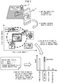
- FIG. 1 is a schematic diagram for explaining an outline of an image evaluation system.
- the image evaluation system includes a sensor terminal 2 located for each agricultural field, a portable terminal 4 owned by each user who runs the corresponding agricultural field, and a server 5 which communicates with the portable terminal 4.
- the server 5 searches for a living organism image similar to a captured image transmitted from the portable terminal 4 and transmits a name related to the aspect of a living organism corresponding to the found living organism image to the portable terminal 4 as an evaluation result name.
- the living organism image may include images of living organisms such as plants, animals, and insects, and images of symptoms of diseases of plants including, e.g., crops, and examples of the name related to the aspect of a living organism may include the names of living organisms such as the names of plants, animals, and insects, and the names of diseases.
- the name of an insect pest or a disease corresponding to a captured image of an insect pest or a captured image of symptoms of a disease of a crop is searched for, and the found name of an insect pest or a disease is transmitted to the portable terminal 4 as an evaluation result name.
- the portable terminal 4 is implemented as a multifunctional mobile phone (so-called “smartphone”), but it may also be implemented as, e.g., a mobile phone (so-called “feature phone”), a PDA (Personal Digital Assistant), a portable game machine, a portable music player, or a tablet PC.
- An image evaluation system which searches for the name of an insect pest or a disease corresponding to a captured image of an insect pest or a captured image of symptoms of a disease of a crop and transmits the found name of an insect pest or a disease to the portable terminal 4 as an evaluation result name will be taken as an example below.
- An insect pest or a crop disease will sometimes be referred to as disease or insect damage hereinafter, and the name of an insect pest or a disease will sometimes be referred to as the name of disease or insect damage hereinafter.
- an image capture function built into the portable terminal 4 is used to capture an insect pest inhabiting an agricultural field A run by a user who owns the portable terminal 4, or symptoms of a disease of a crop bred in the agricultural field A (1).
- the portable terminal 4 transmits the captured image to the server 5 (2).
- the server 5 stores disease or insect damage images corresponding to respective types of disease or insect damage, and occurrence environmental information representing the range of environmental information in which these types of disease or insect damage easily occur.
- the environmental information in which disease or insect damage easily occurs exemplifies environmental information suitable for the aspect of a living organism.
- the disease or insect damage image is an image obtained by capturing actual disease or insect damage and is stored in the server 5 in association with the name of disease or insect damage evaluated by an agricultural expert or the like.
- the environmental information means data representing environmental factors such as the ambient temperature, the relative humidity, the soil temperature, the soil moisture content, the amount of solar radiation, the soil electrical conductivity, the soil pH level, the wind direction and speed, the saturation deficit, the dew-point temperature, the water level, the water temperature, and CO 2 measured by the sensor terminal 2 located in each agricultural field, and precipitation information acquired from an external server.
- the occurrence environmental information means data representing, e.g., the range of environmental information or the conditions of an agricultural field in which disease or insect damage easily occurs, and the occurrence environmental information of rice blast, for example, includes an ambient temperature range of 15°C to 25°C and a leaf wetting time of 8 or more hours.
- the server 5 receives the captured image transmitted from the portable terminal 4.
- the server 5 searches for a disease or insect damage image similar to the captured image received from the portable terminal 4 among the stored disease or insect damage images and assigns points to the names of respective types of disease or insect damage based on the found disease or insect damage image (3).
- the server 5 uses, e.g., the SURF (Speeded Up Robust Features) method to extract feature points from each stored disease or insect damage image to calculate a local feature amount for each feature point.
- the server 5 represents the calculated local feature amounts using feature vectors such as Fisher vectors and generates a classification model for the feature vectors using machine learning such as Random Forest.
- the server 5 extracts feature points from the captured image transmitted from the portable terminal 4, calculates local feature amounts for the feature points, and represents the calculated local feature amounts using feature vectors. Using the feature vectors and the classification model for the captured image, a disease or insect damage image similar to the captured image transmitted from the portable terminal 4 is searched for, and a point is assigned to the name of each type of disease or insect damage corresponding to the found disease or insect damage image.
- the classification model uses, e.g., decision trees in Random Forest.
- the point means, e.g., the number of votes for the name of disease or insect damage corresponding to a disease or insect damage image decided for each decision tree in Random Forest.
- the server 5 receives from the sensor terminal 2, environmental information measured by the sensor terminal 2.
- the server 5 specifies environmental information in the agricultural field A received from the sensor terminal 2 and evaluates occurrence environmental information including the specified environmental information.
- the server 5 extracts the name of disease or insect damage associated with the occurrence environmental information determined to include the specified environmental information and weights a point corresponding to the extracted name of disease or insect damage (4).
- the server 5 transmits the name of disease or insect damage corresponding to the highest point among points corresponding to the names of respective types of disease or insect damage to the portable terminal 4 as an evaluation result name.
- the user transmits an image of disease or insect damage captured by the portable terminal 4 to the server 5, in order to know, as an evaluation result name, the name of disease or insect damage that is based on image classification using the captured image of disease or insect damage and is adapted to environmental information in an agricultural field run by him or her.
- the image evaluation system can search for disease or insect damage based not only on image information representing disease or insect damage accumulated in advance, but also on environmental information in an agricultural field, thus improving the accuracy of evaluation of a captured image of disease or insect damage.
- FIG. 1 The above description with reference to FIG. 1 is merely to foster an understanding of details of the present invention. More specifically, the present invention may be carried out in each following embodiment and by various modifications without substantially departing from the principles of the present invention. All such modifications fall within the scope of disclosure of the present invention and the present specification.
- FIG. 2 is a block diagram illustrating an exemplary schematic architecture of an agricultural management system 1.
- the agricultural management system 1 includes one or more sensor terminals 2, a sensor base station 3, portable terminals 4, and a server 5.
- the agricultural management system 1 exemplifies an image evaluation system.
- the sensor terminal or sensor terminals 2 and the sensor base station 3 are connected to each other via a sensor network 7.
- the sensor terminals 2 and the server 5 are connected to each other via a communication network and via, e.g., the sensor network 7, the sensor base station 3, a base station 6, a backbone network 9, a gateway 10, and the Internet 11.
- the agricultural management system 1 may even include sensor base stations 3 in correspondence with the number of sensor terminals 2.
- the portable terminals 4 and a base station 6 are connected to each other via a wireless communication network 8.
- the portable terminals 4 and the server 5 are connected to each other via a communication network and via, e.g., the wireless communication network 8, the base station 6, the backbone network 9, the gateway 10, and the Internet 11.
- the base station 6 serves as a wireless device which connects the sensor base station 3 and the backbone network 9 to each other, connects the portable terminals 4 to each other, or connects the portable terminals 4 and the backbone network 9 to each other, and a plurality of base stations 6 are connected to the backbone network 9.
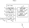
- FIG. 3 is a block diagram illustrating an exemplary schematic configuration of the sensor terminal 2.
- the sensor terminal 2 acquires environmental information representing measured environmental factors, transmits the environmental information, and the like. Therefore, the sensor terminal 2 includes a sensor terminal communication unit 21, a sensor terminal storage unit 22, a GPS (Global Positioning System) unit 23, a sensor connection unit 24, a sensor unit 25, and a sensor terminal processing unit 26.
- a sensor terminal communication unit 21 a sensor terminal storage unit 22 a GPS (Global Positioning System) unit 23 a sensor connection unit 24, a sensor unit 25, and a sensor terminal processing unit 26.
- GPS Global Positioning System
- the sensor terminal communication unit 21 includes a communication interface circuit, including an antenna mainly having a 920-MHz sensitive band, and connects the sensor terminal 2 to the sensor network 7.
- the sensor terminal communication unit 21 uses a specific channel to wirelessly communicate with the sensor base station 3 based on, e.g., the specified low-power wireless scheme.
- the frequency band of the sensor terminal communication unit 21 is not limited to the above-mentioned one.
- the sensor terminal communication unit 21 transmits environmental information supplied from the sensor terminal processing unit 26 to the sensor base station 3.
- the sensor terminal storage unit 22 includes, e.g., a semiconductor memory.
- the sensor terminal storage unit 22 stores, e.g., driver programs, operating system programs, and data used in processing by the sensor terminal processing unit 26.
- the sensor terminal storage unit 22 stores, as the driver programs, a wireless communication device driver program for controlling the sensor terminal communication unit 21, a GPS driver program for controlling the GPS unit 23, a sensor driver program for controlling the sensor unit 25, and the like.
- the sensor terminal storage unit 22 further stores, as the operating system programs, a wireless control program for executing, e.g., the specified low-power wireless scheme, and the like.
- the sensor terminal storage unit 22 further stores, as the data, environmental information representing environmental factors measured by the sensor unit 25.
- the GPS unit 23 includes a GPS circuit, including an antenna mainly having a 1.5-GHz sensitive band, and receives a GPS signal from a GPS satellite (not illustrated).
- the GPS unit 23 decodes the GPS signal to acquire time instant information and the like.
- the GPS unit 23 calculates the pseudo-distance from the GPS satellite to the sensor terminal 2 based on the time instant information and the like and solves simultaneous equations obtained by substituting this pseudo-distance to detect the position (e.g., the latitude, the longitude, and the altitude) of the sensor terminal 2.
- the GPS unit 23 associates positional information representing the detected position and the acquired time instant information with each other and periodically outputs them to the sensor terminal processing unit 26.
- the sensor connection unit 24 includes a sensor terminal to be connected to the sensor unit 25 and is connected to the sensor unit 25 for measuring one or more types of environmental factors.
- the sensor unit 25 includes various sensors for measuring environmental factors such as the ambient temperature, the relative humidity, the soil temperature, the soil moisture content, the amount of solar radiation, the soil electrical conductivity, the soil pH level, the wind direction and speed, the saturation deficit, the dew-point temperature, the water level, the water temperature, and CO 2 .
- the sensor unit 25 includes at least one of, e.g., an ambient temperature sensor for measuring the ambient temperature, a relative humidity sensor for measuring the humidity, a soil temperature sensor for measuring the soil temperature, a soil moisture sensor for measuring the soil moisture content, a solar radiation sensor for measuring the amount of solar radiation, a soil EC (Electrical Conductivity) sensor for measuring the soil electrical conductivity, a soil pH sensor for measuring the soil pH level, wind direction and speed sensors, a dew-point temperature sensor, a water level sensor, a water temperature sensor, and a CO 2 sensor.
- an ambient temperature sensor for measuring the ambient temperature
- a relative humidity sensor for measuring the humidity
- a soil temperature sensor for measuring the soil temperature
- a soil moisture sensor for measuring the soil moisture content
- a solar radiation sensor for measuring the amount of solar radiation
- a soil EC (Electrical Conductivity) sensor for measuring the soil electrical conductivity
- a soil pH sensor for measuring the soil pH level
- wind direction and speed sensors e.g., a dew-point
- the sensor terminal processing unit 26 includes one or more processors and their peripheral circuits.
- the sensor terminal processing unit 26 performs centralized control over the operation of the entire sensor terminal 2 and serves as, e.g., a CPU (Central Processing Unit).
- the sensor terminal processing unit 26 controls the operations of, e.g., the sensor terminal communication unit 21, the GPS unit 23, and the sensor unit 25 to perform various processes of the sensor terminal 2 in an appropriate order in accordance with, e.g., the programs stored in the sensor terminal storage unit 22.
- the sensor terminal processing unit 26 performs processing based on the programs (e.g., driver programs and operating system programs) stored in the sensor terminal storage unit 22.
- the sensor terminal processing unit 26 includes a measured information acquisition unit 261 and a measured information transmission unit 262. Each of these units of the sensor terminal processing unit 26 serves as a functional module implemented by a program executed on the processor of the sensor terminal processing unit 26. Alternatively, each of these units of the sensor terminal processing unit 26 may be implemented in the sensor terminal 2 as an independent integrated circuit, microprocessor, or firmware.
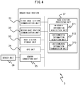
- FIG. 4 is a block diagram illustrating an exemplary schematic configuration of the sensor base station 3.
- the sensor base station 3 receives environmental information from the sensor terminal 2, acquires environmental information representing measured environmental factors, transmits the environmental information, and the like. Therefore, the sensor base station 3 includes a first base station communication unit 31, a second base station communication unit 32, a base station storage unit 33, a GPS unit 34, a sensor connection unit 35, a sensor unit 36, and a base station processing unit 37.
- the first base station communication unit 31 includes a communication interface circuit, including an antenna mainly having a 920-MHz sensitive band, and connects the sensor base station 3 to the sensor network 7.
- the first base station communication unit 31 uses a specific channel to wirelessly communicate with the sensor terminal 2 based on, e.g., the specified low-power wireless scheme.
- the frequency band of the first base station communication unit 31 is not limited to the above-mentioned one.
- the first base station communication unit 31 receives environmental information transmitted from the sensor terminal 2 and supplies the received environmental information to the base station processing unit 37.
- the second base station communication unit 32 includes a communication interface circuit, including an antenna mainly having a 2.4- or 5-GHz sensitive band or the like, and wirelessly communicates with the base station 6 of a wireless LAN (Local Area Network) (not illustrated) based on the IEEE (The Institute of Electrical and Electronics Engineers, Inc.) 802.11 standard wireless communication scheme.
- the frequency band of the second base station communication unit 32 is not limited to the above-mentioned one.
- the second base station communication unit 32 transmits environmental information supplied from the base station processing unit 37 to the base station 6.
- the base station storage unit 33 includes, e.g., a semiconductor memory.
- the base station storage unit 33 stores, e.g., driver programs, operating system programs, and data used in processing by the base station processing unit 37.
- the base station storage unit 33 stores, as the driver programs, a wireless communication device driver program for controlling the first base station communication unit 31, a wireless LAN communication device driver program for controlling the second base station communication unit 32, a GPS driver program for controlling the GPS unit 34, a sensor driver program for controlling the sensor unit 25, and the like.
- the base station storage unit 33 further stores, as the operating system programs, a wireless control program for executing, e.g., the specified low-power wireless scheme, a connection control program for executing the IEEE 802.11 standard wireless communication scheme, and the like.
- the base station storage unit 33 further stores, as the data, environmental information representing environmental factors measured by the sensor unit 36, and environmental information received from the sensor terminal 2.
- the GPS unit 34 includes a GPS circuit, including an antenna mainly having a 1.5-GHz sensitive band, and receives a GPS signal from a GPS satellite (not illustrated).
- the GPS unit 34 decodes the GPS signal to acquire time instant information and the like.
- the GPS unit 34 calculates the pseudo-distance from the GPS satellite to the sensor base station 3 based on the time instant information and the like and solves simultaneous equations obtained by substituting this pseudo-distance to detect the position (e.g., the latitude, the longitude, and the altitude) of the sensor base station 3.
- the GPS unit 34 associates positional information representing the detected position and the acquired time instant information with each other and periodically outputs them to the base station processing unit 37.
- the sensor connection unit 35 includes a sensor terminal to be connected to the sensor unit 36 and is connected to the sensor unit 36 for measuring one or more types of environmental factors.
- the sensor unit 36 includes various sensors for measuring environmental factors such as the ambient temperature, the relative humidity, the soil temperature, the soil moisture content, the amount of solar radiation, the soil electrical conductivity, the soil pH level, the wind direction and speed, the saturation deficit, the dew-point temperature, the water level, the water temperature, and CO 2 .
- the sensor unit 36 includes at least one of, e.g., an ambient temperature sensor for measuring the ambient temperature, a relative humidity sensor for measuring the humidity, a soil temperature sensor for measuring the soil temperature, a soil moisture sensor for measuring the soil moisture content, a solar radiation sensor for measuring the amount of solar radiation, a soil EC (Electrical Conductivity) sensor for measuring the soil electrical conductivity, a soil pH sensor for measuring the soil pH level, wind direction and speed sensors, a dew-point temperature sensor, a water level sensor, a water temperature sensor, and a CO 2 sensor.
- an ambient temperature sensor for measuring the ambient temperature
- a relative humidity sensor for measuring the humidity
- a soil temperature sensor for measuring the soil temperature
- a soil moisture sensor for measuring the soil moisture content
- a solar radiation sensor for measuring the amount of solar radiation
- a soil EC (Electrical Conductivity) sensor for measuring the soil electrical conductivity
- a soil pH sensor for measuring the soil pH level
- wind direction and speed sensors e.g., a dew-point
- the base station processing unit 37 includes one or more processors and their peripheral circuits.
- the base station processing unit 37 performs centralized control over the operation of the entire sensor base station 3 and serves as, e.g., a CPU (Central Processing Unit).
- the base station processing unit 37 controls the operations of, e.g., the first base station communication unit 31, the second base station communication unit 32, the GPS unit 34, and the sensor unit 36 to perform various processes of the sensor base station 3 in an appropriate order in accordance with, e.g., the programs stored in the base station storage unit 33.
- the base station processing unit 37 performs processing based on the programs (e.g., driver programs and operating system programs) stored in the base station storage unit 33.
- the base station processing unit 37 includes a measured information acquisition unit 371, an environmental information reception unit 372, and an environmental information transmission unit 373. Each of these units of the base station processing unit 37 serves as a functional module implemented by a program executed on the processor of the base station processing unit 37. Alternatively, each of these units of the base station processing unit 37 may be implemented in the sensor base station 3 as an independent integrated circuit, microprocessor, or firmware.
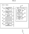
- FIG. 5 is a block diagram illustrating an exemplary schematic configuration of the portable terminal 4.
- the portable terminal 4 transmits user information, receives the history and range information of environmental information in an agricultural field, displays the history and range information of the environmental information, and the like. Therefore, the portable terminal 4 includes a first wireless communication unit 41, a second wireless communication unit 42, a terminal storage unit 43, an operation unit 44, a display unit 45, an image capture unit 46, and a terminal processing unit 47.
- the first wireless communication unit 41 includes a communication interface circuit, including an antenna mainly having a 2.1-GHz sensitive band, and connects the portable terminal 4 to a communication network (not illustrated).
- the first wireless communication unit 41 establishes a wireless signal channel based on, e.g., CDMA (Code Division Multiple Access) with the base station 6 via a channel assigned by the base station 6 to communicate with the base station 6.
- CDMA Code Division Multiple Access
- the scheme of communication with the base station 6 is not limited to CDMA, and other communication schemes such as W-CDMA (Wideband Code Division Multiple Access) or LTE (Long Term Evolution) may also be employed, or communication schemes to be used in the future may even be employed.
- the scheme of communication with the base station 6 may even be other communication schemes such as PHS (Personal Handy-phone System).
- the frequency band of the first wireless communication unit 41 is not limited to the above-mentioned one.
- the first wireless communication unit 41 supplies data received from the base station 6 to the terminal processing unit 47 and transmits
- the second wireless communication unit 42 includes a communication interface circuit, including an antenna mainly having a 2.4- or 5-GHz sensitive band or the like, and wirelessly communicates with an access point of a wireless LAN (Local Area Network) (not illustrated) based on the IEEE (The Institute of Electrical and Electronics Engineers, Inc.) 802.11 standard wireless communication scheme.
- the frequency band of the second wireless communication unit 42 is not limited to the above-mentioned one.
- the second wireless communication unit 42 supplies data received from the base station 6 to the terminal processing unit 47 and transmits data supplied from the terminal processing unit 47 to the base station 6.
- the terminal storage unit 43 includes, e.g., a semiconductor memory.
- the terminal storage unit 43 stores, e.g., driver programs, operating system programs, application programs, and data used in processing by the terminal processing unit 47.
- the terminal storage unit 43 stores, as the driver programs, a mobile phone communication device driver program for controlling the first wireless communication unit 41, a wireless LAN communication device driver program for controlling the second wireless communication unit 42, an input device driver program for controlling the operation unit 44, an output device driver program for controlling the display unit 45, and the like.
- the terminal storage unit 43 further stores, as the operating system programs, a connection control program for executing the IEEE 802.11 standard wireless communication scheme, a mobile phone connection control program, and the like.
- the terminal storage unit 43 further stores, as the application programs, a Web browser program for retrieving and displaying a Web page, an email program for sending and receiving email, and the like.
- Computer programs may also be installed on the terminal storage unit 43 using, e.g., a known setup program from a computer-readable portable recording medium such as a CD-ROM (Compact Disk Read Only Memory) or a DVD-ROM (Digital Versatile Disk Read Only Memory).
- the operation unit 44 may be implemented as any device as long as it allows the operation of the portable terminal 4, and a touch panel input device or a keypad, for example, may be used.
- the owner can input characters, figures, and the like using this device.
- the operation unit 44 upon being operated by the owner, generates a signal corresponding to the operation.
- the generated signal is input to the terminal processing unit 47 as an owner's instruction.
- the display unit 45 may be implemented as any device as long as it can output video and still images, and the like, and a touch panel display, a liquid crystal display, or an organic EL (Electro-Luminescence) display, for example, may be used.
- the display unit 45 displays a video image according to video image data, a still image according to still image data, and the like supplied from the terminal processing unit 47.
- the image capture unit 46 includes, e.g., an imaging optical system, an image sensor, and an image processing unit.
- the imaging optical system is implemented as, e.g., an optical lens and forms an image of a light beam from an object on the image sensing plane of the image sensor.
- the image sensor is implemented as, e.g., a CCD (Charge Coupled Device) or a CMOS (Complementary Metal Oxide Semiconductor) and outputs an image signal of the object image formed on the image sensing plane.
- the image processing unit creates and outputs image data in a predetermined file format from the image signal generated by the image sensor.
- the terminal processing unit 47 includes one or more processors and their peripheral circuits.
- the terminal processing unit 47 performs centralized control over the operation of the entire portable terminal 4 and serves as, e.g., a CPU (Central Processing Unit).
- the terminal processing unit 47 controls the operations of, e.g., the first wireless communication unit 41, the second wireless communication unit 42, and the display unit 45 to perform various processes of the portable terminal 4 in an appropriate order in accordance with, e.g., the programs stored in the terminal storage unit 43 and output from the operation of the operation unit 44.
- the terminal processing unit 47 performs processing based on the programs (e.g., driver programs, operating system programs, and application programs) stored in the terminal storage unit 43.
- the terminal processing unit 47 can also execute a set of programs (e.g., application programs) in parallel.
- the terminal processing unit 47 includes a browsing execution unit 471, an acquisition unit 472, and a terminal transmission unit 473. Each of these units of the terminal processing unit 47 serves as a functional module implemented by a program executed on the processor of the terminal processing unit 47. Alternatively, each of these units of the terminal processing unit 47 may be implemented in the portable terminal 4 as an independent integrated circuit, microprocessor, or firmware.
- FIG. 6 is a block diagram illustrating an exemplary schematic configuration of the server 5.
- FIGS. 7A to 7D are tables illustrating exemplary data structures of various tables stored in a server storage unit 52.
- the server 5 upon receiving environmental information from the sensor terminal 2 or the sensor base station 3, accumulates and manages the environmental information and transmits, e.g., the environmental information and the range information of the environmental information to the portable terminal 4. Further, the server 5, upon receiving a captured image of disease or insect damage transmitted from the portable terminal 4, searches for the name of disease or insect damage corresponding to the captured image and transmits the found name of disease or insect damage to the portable terminal 4 as an evaluation result name. Therefore, the server 5 includes a server communication unit 51, a server storage unit 52, and a server processing unit 53.
- the server communication unit 51 includes a communication interface circuit for connecting the server 5 to the Internet 11.
- the server communication unit 51 receives data transmitted from the sensor terminal 2 or the sensor base station 3 and data transmitted from the portable terminal 4 and supplies these received data to the server processing unit 53.
- the server storage unit 52 includes at least one of, e.g., a semiconductor memory, a magnetic disk device, and an optical disk device.
- the server storage unit 52 stores, e.g., driver programs, operating system programs, application programs, and data used in processing by the server processing unit 53.
- the server storage unit 52 stores, as the driver programs, a communication device driver program for controlling the server communication unit 51, and the like.
- Computer programs may also be installed on the server storage unit 52 using, e.g., a known setup program from a computer-readable portable recording medium such as a CD-ROM or a DVD-ROM.
- the server storage unit 52 further stores, as the data, a user management table illustrated in FIG. 7A , a sensor management table illustrated in FIG. 7B , a range management table illustrated in FIG. 7C , an evaluation history table illustrated in FIG. 7D , various image data associated with screen display, and the like.
- the server storage unit 52 may further temporarily store temporary data associated with predetermined processing.
- FIG. 7A illustrates a user management table for managing users.
- the user management table stores, for each user, pieces of information such as the identification number of this user (user ID), the name of this user, the email address of this user, and the identification number of the sensor terminal 2 and the sensor base station 3 (sensor ID) in association with each other.
- the sensor terminal ID means the identification number of the sensor terminal 2 owned by the user.
- FIG. 7B illustrates a sensor management table for managing the sensor terminals 2 and the sensor base station 3.
- the sensor management table stores, for each sensor terminal 2 and the sensor base station 3, pieces of information such as the identification number of this sensor terminal 2 and the sensor base station 3 (sensor ID), the sensor position, the identification number of an agricultural field (agricultural field ID), the identification number of a crop (crop ID), the current growth stage, the lower limit evaluation value, and pieces of record-specific environmental information in association with each other.
- the sensor position is defined by the latitude and longitude acquired by the GPS units of each sensor terminal 2 and the sensor base station 3, transmitted from this sensor terminal 2 and the sensor base station 3.
- the agricultural field ID means the identification number of an agricultural field in which each sensor terminal 2 and the sensor base station 3 are located.
- the crop ID means the identification number of a crop cultivated in an agricultural field in which each sensor terminal 2 and the sensor base station 3 are located.
- the growth stage is defined by growth condition-specific divisions of the growth duration in which each crop is bred, and a plurality of growth stages are set for each type of crop. Examples of the growth stage may include the sowing, seedling cultivation, and rooting stages.
- the current growth stage is of a crop bred in an agricultural field in which each sensor terminal 2 and the sensor base station 3 are located.
- the current growth stage is updated to the next growth stage when the server 5 receives a growth stage update request transmitted from the user.
- the lower limit evaluation value means the lower limit of the outcome value desired by the user among the outcome values of a crop bred in an agricultural field in which each sensor terminal 2 and the sensor base station 3 are located.
- the lower limit evaluation value is set by the user, but it may also be set to a certain evaluation value.
- the pieces of record-specific environmental information are stored as sequentially associated in accordance with the measurement time for each sensor ID, based on the sensor ID, the environmental information, and the measurement time transmitted from the sensor base station 3 in a predetermined server transmission cycle.
- environmental information at the first measurement time is stored as one record, and each record is stored as record 1, record 2, record 3,... in the order of measurement.
- the environmental information includes the ambient temperature, the relative humidity, the soil temperature, the soil moisture content, the amount of solar radiation, the soil electrical conductivity, the soil pH level, the wind direction and speed, the saturation deficit, the dew-point temperature, the water level, the water temperature, and/or CO 2 , but it may also include other environmental factors, or it may even include the accumulated value of each environmental factor.
- the growth stage included in each record the current growth stage at the moment of storage of environmental information is stored.
- FIG. 7C illustrates a range management table for managing the range information of environmental information.
- the range management table stores, for each crop, the identification number of this crop (crop ID), the range information of environmental information involved to harvest a crop for each growth stage, and the like in association with each other.
- FIG. 7D illustrates an evaluation history table for managing the evaluation value of a crop bred in the past.
- the evaluation history table stores, for each sensor terminal 2 and sensor base station 3, the identification number of this sensor terminal 2 and sensor base station 3 (sensor ID), the evaluation history of a crop harvested in an agricultural field in which this sensor terminal 2 and sensor base station 3 are located, and the like in association with each other.
- the evaluation history includes, e.g., the growth duration of a crop harvested in the past, and an evaluation value representing the outcome value of the crop.
- a storage processing unit 535 may also store the evaluation history stored in the evaluation history table and the agricultural field ID and/or the crop ID stored in the sensor management table, in the server storage unit 52 in association with each other.
- the server processing unit 53 includes one or more processors and their peripheral circuits.
- the server processing unit 53 performs centralized control over the operation of the entire server 5 and serves as, e.g., a CPU.
- the server processing unit 53 controls the operation of, e.g., the server communication unit 51 to perform various processes of the server 5 in an appropriate order in accordance with, e.g., the programs stored in the server storage unit 52.
- the server processing unit 53 performs processing based on the programs (e.g., driver programs, operating system programs, and application programs) stored in the server storage unit 52.
- the server processing unit 53 can also execute a set of programs (e.g., application programs) in parallel.
- the server processing unit 53 includes a server reception unit 531, a registration unit 532, a screen creation unit 533, a server transmission unit 534, a storage processing unit 535, a warning unit 536, a correction unit 537, a specifying unit 538, and an image evaluation unit 539.
- Each of these units of the server processing unit 53 serves as a functional module implemented by a program executed on the processor of the server processing unit 53.
- each of these units of the server processing unit 53 may be implemented in the server 5 as an independent integrated circuit, microprocessor, or firmware.
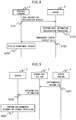
- FIG. 8 is a chart illustrating an exemplary operation sequence associated with the agricultural management system 1.
- the operation sequence illustrated in FIG. 8 exemplifies user information registration processing shared between the portable terminal 4 and the server 5.
- the following operation sequence is executed mainly by the terminal processing unit 47 and the server processing unit 53 in cooperation with the elements of the portable terminal 4 and the server 5, based on the programs stored in the terminal storage unit 43 and the server storage unit 52 in advance.
- the browsing execution unit 471 of the portable terminal 4 transmits user information input using the operation unit 44 by the user to the server 5 via the second wireless communication unit 42, together with a user information registration request (step S101).
- the server reception unit 531 of the server 5 receives via the server communication unit 51, the user information transmitted from the portable terminal 4.
- the user information includes, e.g., the name of the user, the email address of the user, the sensor ID of the sensor terminal 2 owned by the user and the sensor base station, an agricultural field ID corresponding to this sensor ID, the crop ID, the current growth stage, the lower limit evaluation value, and the range information of environmental information involved to harvest a crop for each growth stage.
- a unique ID may be assigned by the server 5 based on the name of an agricultural field input using the operation unit 44 by the user.
- a unique ID may be assigned by the server 5 based on the type of crop input using the operation unit 44 by the user.
- the registration unit 532 performs user information registration processing for registering the user information received by the server reception unit 531 in various tables recorded in the server storage unit 52 (step S102).
- the screen creation unit 533 creates management screen display data including the user information registered by the registration unit 532.
- the server transmission unit 534 transmits the created management screen display data to the portable terminal 4 via the server communication unit 51 (step S103).
- the browsing execution unit 471 of the portable terminal 4 displays a management screen (not illustrated) including the registered user information, based on the management screen display data received via the second wireless communication unit 42 (step S104).
- FIG. 9 is a chart illustrating another exemplary operation sequence associated with the agricultural management system 1.
- the operation sequence illustrated in FIG. 9 exemplifies environmental information storage processing shared among the sensor terminal 2, the sensor base station 3, and the server 5.
- the following operation sequence is executed mainly by the sensor terminal processing unit 26, the base station processing unit 37, and the server processing unit 53 in cooperation with the elements of the sensor terminal 2, the sensor base station 3, and the server 5, based on the programs stored in the sensor terminal storage unit 22, the base station storage unit 33, and the server storage unit 52 in advance.
- the measured information acquisition unit 261 of the sensor terminal 2 acquires environmental information representing environmental factors measured by the sensor unit 25 from the sensor unit 25 via the sensor connection unit 24 in a predetermined measurement cycle and also acquires time instant information periodically output from the GPS unit 23.
- the measured information acquisition unit 261 stores the environmental information acquired from the sensor unit 25 and the time instant information acquired from the GPS unit 23 in the sensor terminal storage unit 22 in association with a sensor ID for identifying the sensor terminal 2.
- the measured information transmission unit 262 transmits the sensor ID, the environmental information, and the measurement time stored in the sensor terminal storage unit 22 to the sensor base station 3 via the sensor terminal communication unit 21 in a predetermined transmission cycle (step S201).
- the measured information acquisition unit 371 of the sensor base station 3 acquires environmental information representing environmental factors measured by the sensor unit 36 from the sensor unit 36 via the sensor connection unit 35 in a predetermined measurement cycle and also acquires time instant information periodically output from the GPS unit 34.
- the measured information acquisition unit 371 stores the environmental information acquired from the sensor unit 36 and the time instant information acquired from the GPS unit 34 in the base station storage unit 33 in association with a sensor ID for identifying the sensor base station 3.
- the environmental information reception unit 372 receives via the first base station communication unit 31, the sensor ID, the environmental information, and the measurement time transmitted from the sensor terminal 2 in a predetermined transmission cycle.
- the environmental information reception unit 372 stores the received sensor ID, the environmental information, and the measurement time in the base station storage unit 33.
- the environmental information transmission unit 373 transmits the sensor ID, the environmental information, and the measurement time stored in the base station storage unit 33 to the server 5 via the second base station communication unit 32 in a predetermined server transmission cycle (step S202).
- the server reception unit 531 of the server 5 receives via the server communication unit 51, the sensor ID, the environmental information, and the measurement time transmitted from the sensor base station 3 in a predetermined server transmission cycle.
- the storage processing unit 535 sequentially stores the received measurement time and environmental information in the sensor management table of the server storage unit 52 for each record in association with the sensor ID received at the same time (step S203).
- FIG. 10 is a chart illustrating still another exemplary operation sequence associated with the agricultural management system 1.
- the operation sequence illustrated in FIG. 10 exemplifies range information registration processing shared between the portable terminal 4 and the server 5.
- the following operation sequence is executed mainly by the terminal processing unit 47 and the server processing unit 53 in cooperation with the elements of the portable terminal 4 and the server 5, based on the programs stored in the terminal storage unit 43 and the server storage unit 52 in advance.
- the browsing execution unit 471 of the portable terminal 4 transmits a crop ID for identifying a crop input using the operation unit 44 by the user and the range information of environmental information involved to harvest a crop having each evaluation value to the server 5 via the second wireless communication unit 42, together with a request to register the range information of the environmental information (step S301).
- the range information of environmental information involved to harvest a crop having each evaluation value will sometimes be referred to as the range information of environmental information corresponding to each evaluation value hereinafter.
- the server reception unit 531 of the server 5 receives via the server communication unit 51, the crop ID and the range information of environmental information corresponding to each evaluation value transmitted from the portable terminal 4.
- the registration unit 532 associates the crop ID with the range information of environmental information corresponding to each evaluation value and records them in the range management table of the server storage unit 52 (step S302).
- the screen creation unit 533 creates management screen display data including a crop indicated by the crop ID and the range information of environmental information corresponding to both the crop and each evaluation value, recorded in the range management table of the registration unit 532.
- the server transmission unit 534 transmits the created management screen display data to the portable terminal 4 via the server communication unit 51 (step S303).
- the browsing execution unit 471 of the portable terminal 4 displays a management screen (not illustrated) including the registered range information of the environmental information, based on the management screen display data received via the second wireless communication unit 42 (step S304).
- FIG. 11 is a chart illustrating still another exemplary operation sequence associated with the agricultural management system 1.
- the operation sequence illustrated in FIG. 11 exemplifies warning email output processing shared between the portable terminal 4 and the server 5.
- the following operation sequence is executed mainly by the terminal processing unit 47 and the server processing unit 53 in cooperation with the elements of the portable terminal 4 and the server 5, based on the programs stored in the terminal storage unit 43 and the server storage unit 52 in advance.
- the warning unit 536 and the screen creation unit 533 of the server 5 perform warning email output processing in a predetermined warning cycle (step S401).
- the warning email output processing will be described in detail later.
- the server transmission unit 534 receives warning email from the warning unit 536 and transmits the warning email to the portable terminal 4 indicated by the transmission destination address included in the warning email (step S402).
- FIG. 12 is a flowchart illustrating an exemplary operation sequence of warning email output processing by the warning unit 536 and the screen creation unit 533.
- the warning email output processing illustrated in FIG. 12 is performed in step S401 of FIG. 11 .
- the warning unit 536 looks up the sensor management table stored in the server storage unit 52 to acquire environmental information of the latest record in a predetermined warning cycle for each sensor ID (step S501).
- the warning unit 536 further looks up the sensor management table stored in the server storage unit 52 to extract a crop ID and a lower limit evaluation value associated with each sensor ID, for each sensor ID.
- the warning unit 536 looks up the range management table stored in the server storage unit 52 to acquire the range information of environmental information equal to or greater than the lower limit evaluation value (e.g., predetermined values of 4 and 5 when the lower limit evaluation value is 4) in the current growth stage, associated with the extracted crop ID (step S502).
- the lower limit evaluation value exemplifies a predetermined evaluation value.
- the warning unit 536 determines, for each sensor ID, whether the environmental information of the latest record falls within the range information of environmental information equal to or greater than the lower limit evaluation value corresponding to the crop ID associated with each sensor ID (step S503).
- the warning unit 536 determines that the environmental information of the latest record for each sensor ID falls within the range information of environmental information equal to the lower limit evaluation value corresponding to the crop ID associated with each sensor ID (Yes in step S503), it advances the process to step S506 (to be described later).
- the warning unit 536 determines that the environmental information of the latest record for each sensor ID falls outside the range information of environmental information equal to the lower limit evaluation value corresponding to the crop ID associated with each sensor ID (No in step S503), it creates environmental suitability information representing an environment involved to harvest a crop having the lower limit evaluation value.
- the environmental suitability information includes, e.g., information representing the difference between the environmental information of the latest record and the range information of environmental information equal to or greater than the lower limit evaluation value.
- the screen creation unit 533 creates management screen display data including the environmental suitability information created by the warning unit 536 (step S504).
- the warning unit 536 creates warning email including information indicating that the current environmental information falls outside the range information of the environmental information (step S505).
- the warning unit 536 looks up the user management table to specify a user ID associated with a sensor ID corresponding to the environmental information of the latest record determined to fall outside the range information of environmental information equal to the lower limit evaluation value to acquire an email address associated with the specified user ID.
- the warning unit 536 further creates warning email having the acquired email address set as a transmission destination, and information indicating that the current environmental information falls outside the range information of the environmental information set as a text.
- the warning unit 536 passes the created warning email to the server transmission unit 534.
- the warning unit 536 may also include in the warning email, a URL (Uniform Resource Locator) indicating the storage location of management screen display data including the environmental suitability information.
- a URL Uniform Resource Locator
- the warning unit 536 determines whether the processes in steps S503 to S504 have been performed for all sensor IDs stored in the sensor management table (step S506). When the warning unit 536 determines that the processes in steps S503 to S504 have not been performed for all sensor IDs (No in step S506), it returns the process to step S503. When the warning unit 536 determines that the processes in steps S503 to S504 have been performed for all sensor IDs (Yes in step S506), it ends a series of steps.
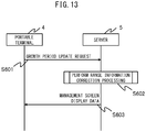
- FIG. 13 is a chart illustrating still another exemplary operation sequence associated with the agricultural management system 1.
- the operation sequence illustrated in FIG. 13 exemplifies range information correction processing shared between the portable terminal 4 and the server 5.
- the following operation sequence is executed mainly by the terminal processing unit 47 and the server processing unit 53 in cooperation with the elements of the portable terminal 4 and the server 5, based on the programs stored in the terminal storage unit 43 and the server storage unit 52 in advance.
- the browsing execution unit 471 of the portable terminal 4 transmits a growth stage update request including the sensor ID and the user ID of the user who owns the portable terminal 4 to the server 5 via the second wireless communication unit 42 (step S601).
- the ended growth stage will be referred to as the current growth stage hereinafter, and the growth stage to be updated by the growth stage update request will be referred to as the next growth stage hereinafter.
- the sensor ID is of the sensor terminal 2 and the sensor base station 3 located in an agricultural field in which a crop whose growth stage has ended is bred.
- the server reception unit 531 of the server 5 receives via the server communication unit 51, the growth stage update request transmitted from the portable terminal 4, the correction unit 537 and the screen creation unit 533 perform range information correction processing (step S602).
- the range information correction processing will be described in detail later.
- the server transmission unit 534 receives management screen display data from the screen creation unit 533 and transmits the management screen display data to the portable terminal 4 (step S603).
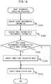
- FIG. 14 is a flowchart illustrating an exemplary operation sequence of range information correction processing by the correction unit 537 and the screen creation unit 533.
- the range information correction processing illustrated in FIG. 14 is performed in step S602 of FIG. 13 .
- the correction unit 537 looks up the sensor management table to acquire environmental information of records in the current growth stage among pieces of environmental information of respective records associated with the sensor ID included in the growth stage update request received by the server reception unit 531 (step S701).
- the correction unit 537 further looks up the sensor management table to extract a crop ID and a lower limit evaluation value associated with the sensor ID included in the growth stage update request and then looks up the range management table to acquire the range information of environmental information equal to or greater than the lower limit evaluation value in the current growth stage associated with the extracted crop ID (step S702).
- the range information of environmental information equal to or greater than the lower limit evaluation value in the current growth stage associated with the extracted crop ID will sometimes be referred to as target range information hereinafter.
- the correction unit 537 determines whether the average of environmental information of records in the current growth stage falls within the target range information (step S703).
- the correction unit 537 may determine that the environmental information of records in the current growth stage falls within the target range information when the number of records of pieces of environmental information that fall within the target range information is equal to or larger than a predetermined number.
- the correction unit 537 advances the process to step S706.
- the correction unit 537 extracts an evaluation value lower than the lower limit evaluation value extracted in step S702 and stores the evaluation value extracted as a lower limit evaluation value associated with the sensor ID included in the growth stage update request in the sensor management table (step S704).
- the lower limit evaluation value and the evaluation value lower than the lower limit evaluation value exemplify a predetermined evaluation value and a second evaluation value.
- the second evaluation value is not limited to such an evaluation value lower than the lower limit evaluation value.
- the correction unit 537 determines whether the average of environmental information of records in the current growth stage falls within the range information of environmental information equal to or greater than the lower limit evaluation value acquired in step S702. When the average of environmental information of records in the current growth stage falls within the range information of environmental information equal to or greater than the lower limit evaluation value, the correction unit 537 sets an evaluation value corresponding to the environmental information equal to or greater than the lower limit evaluation value as a second evaluation value. In this manner, a second evaluation value different from the predetermined evaluation value is extracted in accordance with the environmental information, and the evaluation value is stored in the sensor management table.
- the correction unit 537 acquires the range information of environmental information equal to the second evaluation value in the next growth stage associated with the crop ID extracted in step S702, and the screen creation unit 533 creates management screen display data for displaying a management screen including the extracted range information of the environmental information (step S705).
- the screen creation unit 533 passes the created management screen display data to the server transmission unit 534 and ends a series of steps.
- the warning unit 536 performs the above-mentioned warning email output processing using an evaluation value lower than the lower limit evaluation value.
- FIG. 15 is a chart illustrating still another exemplary operation sequence associated with the agricultural management system 1.
- the operation sequence illustrated in FIG. 15 exemplifies range information update processing shared between the portable terminal 4 and the server 5.
- the following operation sequence is executed mainly by the terminal processing unit 47 and the server processing unit 53 in cooperation with the elements of the portable terminal 4 and the server 5, based on the programs stored in the terminal storage unit 43 and the server storage unit 52 in advance.
- the user uses the operation unit 44 to input the sensor ID of the sensor terminal 2 and the sensor base station 3 located in an agricultural field in which each harvested crop has been bred, and the crop ID, evaluation value, and growth duration of this harvested crop.
- the acquisition unit 472 of the portable terminal 4 acquires the input sensor ID and crop ID, evaluation value, and growth duration.
- the terminal transmission unit 473 transmits to the server 5 via the second wireless communication unit 42, the user ID of the user who owns the portable terminal 4, and harvest data including the sensor ID and the crop ID, evaluation value, and growth duration acquired by the acquisition unit 472 (step S801).
- the server reception unit 531 of the server 5 receives via the server communication unit 51, the harvest data transmitted from the portable terminal 4, the specifying unit 538 and the screen creation unit 533 perform range information update processing (step S802).
- the range information update processing will be described in detail later.
- the server transmission unit 534 receives management screen display data from the screen creation unit 533 and transmits the management screen display data to the portable terminal 4 (step S803).
- FIG. 16 is a flowchart illustrating an exemplary operation sequence of range information update processing by the specifying unit 538 and the screen creation unit 533.
- the range information update processing illustrated in FIG. 16 is performed in step S802 of FIG. 15 .
- the specifying unit 538 looks up the sensor management table to acquire environmental information for each growth stage included in each record among pieces of environmental information of all records associated with the sensor ID and the crop ID included in the harvest data received by the server reception unit 531 (step S901).
- the environmental information acquired in step S901 is related to, but not limited to, the sensor ID included in the harvest data received by the server reception unit 531.
- the specifying unit 538 may acquire pieces of environmental information of all records associated with all sensor IDs stored in the server storage unit 52 and also associated with the crop ID.
- the specifying unit 538 may even classify agricultural fields into groups based on, e.g., the latitude and longitude, the height above sea level, the climate conditions, and the type of soil in each agricultural field and acquire pieces of environmental information of all records associated with a sensor ID corresponding to an agricultural field classified into the same group as that of an agricultural field corresponding to the sensor ID included in the harvest data received by the server reception unit 531 and also associated with the crop ID.
- the specifying unit 538 performs update processing for acquiring the sensor ID and the crop evaluation value and growth duration included in the harvest data received by the server reception unit 531, associating them with the acquired sensor ID, and storing the acquired crop evaluation value and growth duration in the evaluation history table, and looks up the evaluation history table after the update processing to acquire all evaluation histories associated with the sensor ID included in the harvest data received by the server reception unit 531 (step S902).
- the specifying unit 538 associates all pieces of environmental information acquired in step S901 with evaluation values associated with a growth duration including the measurement times of these pieces of environmental information, for each growth stage (step S903).
- a data set obtained by associating an evaluation value and pieces of environmental information with each other will be referred to as an environmental information history D hereinafter.
- the specifying unit 538 selects environmental information having a great influence on the evaluation value from environmental information histories D (step S904).
- the specifying unit 538 performs principal component analysis using the pieces of environmental information of the environmental information histories D as variables to calculate a principal component loading (factor loading) for each variable in the first principal component.
- the specifying unit 538 selects a variable (environmental information) having a principal component loading greater than a predetermined value.
- the specifying unit 538 may select not only the principal component loadings on the first principal component, but also a variable having principal component loadings on the second principal component greater than a predetermined value.
- the range information update processing may be ended without executing subsequent steps S905 to S907.
- the process may advance to step S905 without executing step S904.
- the specifying unit 538 determines whether the evaluation value in the selected environmental information history D and the environmental information have a specific correlation between them (step S905). The correlation between the evaluation value and the environmental information will be described below.
- FIG. 17 is a schematic graph illustrating an environmental information history D mapped onto a two-dimensional plane having the evaluation value and the environmental information as its axes.
- the environmental information illustrated in FIG. 17 uses the accumulated value of the soil temperature, but it may use the accumulated values of other environmental factors (e.g., the ambient temperature or the amount of solar radiation).
- a crop is known to be preferably bred within the range of optimum environmental information in each growth stage to harvest a crop having a high evaluation value.
- a crop having a high evaluation value is harvested at accumulated soil temperatures around 2,300°C. The lower the accumulated soil temperature from 2,300°C, the lower the evaluation value of a harvested crop, and the higher the accumulated soil temperature from 2,300°C, the lower the evaluation value of a harvested crop again.
- a and b are given by equations (3) and (4), respectively.
- [Mathematical 4] b Y ⁇ aX
- step S905 the specifying unit 538 calculates a regression line describing a positive correlation and a regression line describing a negative correlation between the evaluation value and the environmental information and determines that the evaluation value and the environmental information have a specific correlation between them when the absolute value of the coefficient of correlation R xy according to the calculated regression line is 0.8 or more.
- step S905 When the specifying unit 538 determines that the evaluation value and the environmental information have no specific correlation between them (No in step S905), it advances the process to step S907.
- the specifying unit 538 determines that the evaluation value and the environmental information have a specific correlation between them (Yes in step S905), it calculates a lower limit for the environmental information corresponding to each evaluation value in accordance with the regression line describing a positive correlation and also calculates an upper limit for the environmental information corresponding to each evaluation value in accordance with the regression line describing a negative correlation.
- the specifying unit 538 updates and stores the calculated lower and upper limits corresponding to each evaluation value as the range information of the environmental information in the range management table stored in the server storage unit 52 (step S906).
- the screen creation unit 533 creates management screen display data for displaying a management screen including a notification indicating that the range information of the environmental information in the range management table has been updated (step S907).
- the screen creation unit 533 passes the created management screen display data to the server transmission unit 534 and ends a series of steps.
- the specifying unit 538 may determine whether the first principal component score in principal component analysis performed in step S904 and the evaluation value have a specific correlation between them. First, the specifying unit 538 performs principal component analysis using the pieces of environmental information of the environmental information histories D as variables to calculate a first principal component score corresponding to each variable (environmental information). The specifying unit 538 calculates a coefficient of correlation R xy upon defining the first principal component score as x i , the evaluation value associated with a variable (environmental information) corresponding to the first principal component score as y i , and the averages of x i and y i as X and Y in equation (1).
- the specifying unit 538 calculates a regression line describing a positive correlation and a regression line describing a negative correlation between the evaluation value and the first principal component score in accordance with equations (2) to (5), and determines that the evaluation value and the first principal component score have a specific correlation between them when the absolute value of the coefficient of correlation R xy according to the calculated regression line is 0.8 or more.
- the specifying unit 538 determines that the evaluation value and the first principal component score have a specific correlation between them, it calculates a lower limit for the first principal component score corresponding to each evaluation value in accordance with the regression line describing a positive correlation and also calculates an upper limit for the first principal component score corresponding to each evaluation value in accordance with the regression line describing a negative correlation.
- the specifying unit 538 multiplies the calculated lower and upper limits corresponding to each evaluation value by a matrix inverse to an eigenvector calculated by principal component analysis and updates and stores the upper and lower limits corresponding to each variable (environmental information) selected in step S904 as the range information of each piece of environmental information in the range management table stored in the server storage unit 52. This can calculate range information for pieces of environmental information which influence the evaluation value of a harvested crop.
- the server 5 can provide management information for a crop suited to each agricultural field, based on the outcome value and the environmental information history of a crop harvested in the past, in this agricultural field. Therefore, the server 5 can manage an environment suitable for crop breeding for each agricultural field.
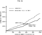
- the screen creation unit 533 of the server 5 may create display data for displaying a screen including agricultural field environment characteristic curves obtained by plotting the accumulated values of the soil temperature and the amount of solar radiation of each record stored in the sensor management table onto a two-dimensional plane having the accumulated soil temperature and the accumulated amount of solar radiation as its axes, and the server transmission unit 534 may transmit the display data to the portable terminal 4 via the server communication unit 51.
- FIG. 18 is a schematic graph illustrating agricultural field environment characteristic curves indicated on a two-dimensional plane having the accumulated soil temperature and the accumulated amount of solar radiation as its axes.
- FIG. 18 represents an agricultural field environment characteristic curve in laboratory X in which a crop having a specific evaluation value of 5 has been harvested, and an agricultural field environment characteristic curve in agricultural field Z of town Y in which a specific crop is bred. This allows visual observation of the discrepancy between the current agricultural field environment characteristic curve in agricultural field Z of town Y and the agricultural field environment characteristic curve in laboratory X.
- FIG. 19 is a chart illustrating still another exemplary operation sequence associated with the agricultural management system 1.
- the operation sequence illustrated in FIG. 19 exemplifies image evaluation processing shared between the portable terminal 4 and the server 5.
- the agricultural management system 1 that executes the operation sequence illustrated in FIG. 19 exemplifies an image evaluation system which executes an image evaluation method.
- the server storage unit 52 stores a disease and insect damage image management table which stores, e.g., disease or insect damage images, the name of disease or insect damage, the name of a crop, an occurrence site, and occurrence environmental information in association with each other, for each type of disease or insect damage.
- the name of a crop means the name of a crop suffering from disease or insect damage.
- Disease or insect damage images are stored in association with each type of disease or insect damage, but only one disease or insect damage image may be stored in association with each type of disease or insect damage.
- the occurrence site means a crop site suffering from disease or insect damage.
- the occurrence environmental information means data representing the range of environmental information or the conditions of an agricultural field, in which disease or insect damage easily occurs. One or more types of environmental information may be used for the occurrence environmental information.
- the acquisition unit 472 acquires a captured image of disease or insect damage obtained by image capturing of the image capture unit 46 in accordance with operation using the operation unit 44 by the user of the portable terminal 4 (step S1001).
- the captured disease or insect damage includes, e.g., an insect inhabiting an agricultural field run by the user who owns the portable terminal 4, or symptoms of a disease of a crop bred in the agricultural field.
- the terminal transmission unit 473 of the portable terminal 4 transmits an image evaluate request including the captured image of disease or insect damage obtained by image capturing of the image capture unit 46 of the portable terminal 4 and the user ID of the user who owns the portable terminal 4 to the server 5 via the second wireless communication unit 42 (step S1002).
- the server reception unit 531 of the server 5 receives via the server communication unit 51, the image evaluate request transmitted from the portable terminal 4, the image evaluation unit 539 and the screen creation unit 533 perform captured image evaluation processing (step S1003).
- the captured image evaluation processing will be described in detail later.
- the server transmission unit 534 receives evaluation result screen display data from the screen creation unit 533 and transmits the evaluation result screen display data to the portable terminal 4 (step S1004).
- the browsing execution unit 471 of the portable terminal 4 displays an evaluation result screen (not illustrated) including an evaluation result name, based on the evaluation result screen display data received via the second wireless communication unit 42 (step S1005).
- FIG. 20 is a flowchart illustrating an exemplary operation sequence of captured image evaluation processing by the image evaluation unit 539 and the screen creation unit 533.
- the captured image evaluation processing illustrated in FIG. 20 is performed in step S 1003 of FIG. 19 .
- the image evaluation unit 539 acquires disease or insect damage images stored in the disease and insect damage image management table and extracts feature points for each acquired disease or insect damage image, using a local feature amount extraction method such as the SURF method, to calculate a local feature amount for each feature point (step S1101).
- the local feature amount extraction method is not limited to the SURF method, and the SIFT (Scale-Invariant Feature Transform) method, for example, may also be used.
- the local feature amount calculated by the local feature amount extraction method has 128 dimensions, but it may also have 64 dimensions or a different number of dimensions without being limited to this example.
- the image evaluation unit 539 represents each disease or insect damage image using feature vectors, based on the local feature amounts calculated for each disease or insect damage image (step S1102).
- the processing for representing a disease or insect damage image using feature vectors is performed using a method for representation by feature vectors such as Fisher vectors.
- feature vectors such as Fisher vectors.
- the image evaluation unit 539 generates a classification model based on the feature vectors representing each disease or insect damage image (step S1103).
- the classification model uses, e.g., decision trees in Random Forest.
- the classification model may be expressed by an objective function introducing a slack variable ⁇ when feature vectors representing each disease or insect damage image are used as learning data in Soft Margin Support Vector Machine.
- the image evaluation unit 539 extracts feature points using a local feature amount extraction method for a captured image included in the image evaluate request received by the server reception unit 531 to calculate a local feature amount for each feature point (step S1104).
- the image evaluation unit 539 represents the captured image using feature vectors, based on the local feature amounts calculated for the captured image (step S1105).
- the image evaluation unit 539 assigns points in association with the name of disease or insect damage similar to the feature vectors representing the captured image, based on the generated classification model (step S1106).
- the point means, e.g., the number of votes for the name of disease or insect damage corresponding to a disease or insect damage image decided for each decision tree in Random Forest.
- the point also acts as a parameter for controlling the penalty of the slack variable ⁇ and the distribution of the margin size in Soft Margin Support Vector Machine.
- the image evaluation unit 539 weights any point associated with the name of disease or insect damage (step S1107).
- the weighting processing will be described hereinafter.
- the image evaluation unit 539 looks up the user management table to acquire a sensor ID associated with a user ID included in the image evaluate request received by the server reception unit 531.
- the image evaluation unit 539 looks up the sensor management table to acquire environmental information and a crop ID of a record in a predetermined duration associated with the acquired sensor ID.
- the predetermined duration is defined as one year, but it may be defined as the growth duration of a crop corresponding to the crop ID associated with the sensor ID.
- the image evaluation unit 539 looks up the disease and insect damage image management table to extract occurrence environmental information associated with the acquired crop ID to determine whether the acquired environmental information is included in the extracted occurrence environmental information.
- the image evaluation unit 539 determines that the acquired environmental information is included in the extracted occurrence environmental information, it looks up the disease and insect damage image management table to specify the name of disease or insect damage associated with the occurrence environmental information determined to include the acquired environmental information and weights the point of the specified name of disease or insect damage. Examples of the processing for weighting the point may include processing for multiplying the point by 1.2.
- the image evaluation unit 539 compares the points associated with the names of respective types of disease or insect damage to determine the name of disease or insect damage assigned with the highest point as an evaluation result name (step S1108).
- the screen creation unit 533 creates evaluation result screen display data including the evaluation result name determined by the image evaluation unit 539 (step S1109), passes the created evaluation result screen display data to the server transmission unit 534, and ends a series of steps.
- the server 5 can search for not only image information of disease or insect damage accumulated in advance, but also disease or insect damage based on environmental information in an agricultural field. Therefore, the server 5 can improve the accuracy of evaluation of a captured image of disease or insect damage.
- a captured image of disease or insect damage obtained by image capturing of the image capture unit 46 in accordance with operation using the operation unit 44 by the user of the portable terminal 4 may be provided by cutting only part of disease or insect damage in accordance with operation using the operation unit 44 by this user.
- the portable terminal 4 transmits an image evaluate request including an image of only part of disease or insect damage to the server 5, and the server 5 performs image evaluation processing using the image, since the image has a relatively small partial region other than the disease or insect damage, the accuracy of the image evaluation processing can be improved.
- step S1101 disease or insect damage images acquired from the disease and insect damage image management table are determined as disease or insect damage images corresponding to the name of a crop and/or the occurrence site included in the image evaluate request. This can determine disease or insect damage images corresponding to a crop and/or an occurrence site suffering from disease or insect damage as objects to be evaluated, thus improving the accuracy of image evaluation processing.
- a sensor ID is acquired from the user management table using, as a key, a user ID included in the image evaluate request received by the server reception unit 531, but it may also be acquired based on the position of the portable terminal 4 having transmitted the image evaluate request.
- the portable terminal 4 includes a GPS unit (not illustrated) which detects the position (e.g., the latitude, the longitude, and the altitude) of the portable terminal 4.
- the acquisition unit 472 of the portable terminal 4 acquires the position (e.g., the latitude, the longitude, and the altitude) detected by the GPS unit as an image capture position upon acquiring a captured image of disease or insect damage by image capturing of the image capture unit 46 in accordance with operation using the operation unit 44 by the user of the portable terminal 4.
- the terminal transmission unit 473 of the portable terminal 4 transmits to the server 5 via the second wireless communication unit 42, an image evaluate request including the captured image of disease or insect damage obtained by image capturing of the image capture unit 46 of the portable terminal 4, the image capture position, and the user ID of the user who owns the portable terminal 4.
- the image evaluation unit 539 looks up the sensor management table to acquire a sensor ID associated with a sensor position near the image capture position received by the server reception unit 531.
- the user can evaluate an image even in an area other than an agricultural field run by him or her.
- the server 5 may acquire from the portable terminal 4 having transmitted the image evaluate request, a sensor ID directly acquired from the sensor terminal 2 by the portable terminal 4.
- the portable terminal 4 having transmitted the image evaluate request establishes communication with a sensor terminal 2 located within the radio propagation range by short-range wireless communication between terminals such as Bluetooth® to directly acquire a sensor ID from the sensor terminal 2 having established communication.
- the portable terminal 4 includes a short-range wireless communication unit 48, in addition to the units illustrated in FIG. 5 .
- the short-range wireless communication unit 48 includes an interface circuit for performing short-range wireless communication in accordance with a communication scheme such as Bluetooth®.
- the acquisition unit 472 of the portable terminal 4 specifies a sensor terminal 2 located within a predetermined range communicable via the short-range wireless communication unit 48 and transmits a sensor ID request signal to the sensor terminal 2.
- the sensor terminal processing unit 26 of the sensor terminal 2 acquires its own sensor ID stored in the sensor terminal storage unit 22 and transmits the acquired sensor ID to the portable terminal 4 having transmitted the sensor ID request signal.
- the terminal transmission unit 473 of the portable terminal 4 further includes the received sensor ID in the image evaluate request and transmits the image evaluate request to the server 5.
- image evaluation processing may be performed based on the information of currently occurring disease or insect damage.
- the server reception unit 531 of the server 5 receives the name of disease or insect damage recognized to have occurred in each agricultural field from each user running this agricultural field, and the acquisition unit 472 of the server 5 stores in the server storage unit 52, a disease and insect damage occurrence table which stores this name of disease or insect damage in association with the agricultural field ID of an agricultural field suffering from disease or insect damage.
- the image evaluation unit 539 looks up the sensor management table to acquire an agricultural field ID associated with a sensor position near the image capture position received by the server reception unit 531.
- the image evaluation unit 539 looks up the disease and insect damage occurrence table to acquire the name of disease or insect damage associated with the agricultural field ID and weights the point of the acquired name of disease or insect damage. This allows image evaluation based on disease or insect damage occurring in an agricultural field around an agricultural field run by the user himself or herself, thus improving the accuracy of evaluation of a captured image of disease or insect damage.
- the server storage unit 52 associates the name of occurring disease or insect damage recognized to be currently occurring and the occurrence position information of the position where disease or insect damage is occurring with each other and stores them.
- the portable terminal 4 includes a GPS unit (not illustrated) which detects the position (e.g., the latitude, the longitude, and the altitude) of the portable terminal 4.
- the acquisition unit 472 of the portable terminal 4 acquires the position (e.g., the latitude, the longitude, and the altitude) detected by the GPS unit as an image capture position upon acquiring a captured image of disease or insect damage by image capturing of the image capture unit 46 in accordance with operation using the operation unit 44 by the user of the portable terminal 4.
- the terminal transmission unit 473 of the portable terminal 4 transmits to the server 5 via the second wireless communication unit 42, an image evaluate request including the captured image of disease or insect damage obtained by image capturing of the image capture unit 46 of the portable terminal 4, the image capture position, and the user ID of the user who owns the portable terminal 4.
- the image evaluation unit 539 determines whether the acquired image capture position falls within a predetermined range having the occurrence position information stored in the server storage unit 52 as its center.
- the image evaluation unit 539 determines that the image capture position falls within the predetermined range, it specifies the name of occurring disease or insect damage corresponding to the occurrence position information and weights the point of the specified name of disease or insect damage.
- the user can evaluate an image based on occurring disease or insect damage data currently occurring all over the country.
- the image evaluation processing by the image evaluation system may also be used to evaluate an animal or plant species other than disease or insect damage.
- the animal or plant species may include a plant, an animal, and an insect.
- the server 5 stores animal or plant species images corresponding to respective animal or plant species, and occurrence environmental information representing the range of environmental information in which this animal or plant species easily occurs.
- the server 5 receives a captured image transmitted from the portable terminal 4.
- the server 5 searches for an animal or plant species image similar to the captured image received from the portable terminal 4 among the stored animal or plant species images and assigns a point to the name of each animal or plant species based on the found animal or plant species image. A point is assigned by the image evaluation unit 539.
- the server 5 receives environmental information measured by the sensor terminal 2 from the sensor terminal 2.
- the server 5 specifies the environmental information in any agricultural field received from the sensor terminal 2 to evaluate occurrence environmental information including the specified environmental information.
- the server 5 extracts the name of an animal or plant species associated with the occurrence environmental information determined to include the specified environmental information and weights a point corresponding to the extracted name of an animal or plant species.
- the server 5 may store positional information in which an animal or plant species easily inhabits and weight a point corresponding to the name of an animal or plant species based on the positional information and the image capture position.
- the server 5 transmits the name of an animal or plant species corresponding to the highest point among points corresponding to the name of each animal or plant species to the portable terminal 4 as an evaluation result name.
- the user can know, as an evaluation result name, the name of an animal or plant species based on image classification using an image of the animal or plant species captured by the portable terminal 4, simply by transmitting the captured image of the animal or plant species to the server 5.
Landscapes
- Engineering & Computer Science (AREA)
- Theoretical Computer Science (AREA)
- General Physics & Mathematics (AREA)
- Physics & Mathematics (AREA)
- Data Mining & Analysis (AREA)
- General Engineering & Computer Science (AREA)
- Databases & Information Systems (AREA)
- Library & Information Science (AREA)
- Life Sciences & Earth Sciences (AREA)
- Ecology (AREA)
- Forests & Forestry (AREA)
- Environmental Sciences (AREA)
- Botany (AREA)
- Biodiversity & Conservation Biology (AREA)
- Multimedia (AREA)
- Management, Administration, Business Operations System, And Electronic Commerce (AREA)
- Processing Or Creating Images (AREA)
- Information Retrieval, Db Structures And Fs Structures Therefor (AREA)
- Testing, Inspecting, Measuring Of Stereoscopic Televisions And Televisions (AREA)
Abstract
Description
- Embodiments discussed in the present specification relates to an image evaluation method for a captured image.
- In recent years, a disease and insect damage search system which searches for the name of disease or insect damage based on, e.g., crop name and symptom input information or captured image information of an agricultural field for breeding a crop is known as a system which automatically searches for an insect pest inhabiting a crop or symptoms of a disease of the crop.
-
Patent literature 1, for example, discloses a plant disease identification system including an image capture unit, an image processing unit, and a phytopathological database which stores the name of a specific plant disease and image information representing the characteristics of the specific disease in association with each other. In the identification system, first, the image capture unit acquires cultivated plant image information, and the image processing unit analyzes the cultivated plant image information acquired by the image capture unit to acquire image information representing a zone suspected to be diseased. The image processing unit then compares the acquired image information of the zone suspected to be diseased with the image information of the characteristics of the disease in the phytopathological database. When the image information of the zone suspected to be diseased matches the image information of the characteristics of the disease in the phytopathological database, the image processing unit acquires the name of the corresponding specific plant disease as a disease identification result. - Patent literature 1: Japanese Unexamined Patent Publication (Kokai) No.
2013-111078 - However, in such a conventional disease and insect damage evaluation system using image search, since an image is classified based on only image information representing disease or insect damage accumulated in advance, the classification accuracy may dramatically degrade depending on the differences in the direction in which an image is captured, the lightness, the resolution, and the like.
- The image evaluation method has been made to solve such a conventional problem, and has as its object to provide an image evaluation method which can improve the accuracy of evaluation of a captured image.
- According to an aspect of an image evaluation method, there is provided an image evaluation method using a server for communicating with a portable terminal and a sensor terminal located in an agricultural field. The server including a storage unit. The method including the steps of, by the server, storing in the storage unit, living organism images corresponding to respective aspects of a living organism, and pieces of occurrence environmental information representing ranges of environmental information suitable for the aspects of the living organism, receiving a captured image transmitted from the portable terminal, receiving the environmental information measured by the sensor terminal from the sensor terminal, searching for a living organism image similar to the received captured image of the living organism images and assigning points to names related to the aspect of the living organism corresponding to the found living organism image, weighting the points of the names related to the aspect of the living organism, associated with the occurrence environmental information comprising the environmental information received from the sensor terminal, by extracting the names, and transmitting a name having a highest point of the points to the portable terminal having transmitted the captured image as an evaluation result name.
- According to an aspect of the image evaluation method, wherein in the step of weighting, the server extracts the names related to the aspect of the living organism, associated with the occurrence environmental information comprising the environmental information received from a sensor terminal near an image capture position of the portable terminal when the aspect of the living organism is captured by the portable terminal.
- According to an aspect of the image evaluation method, further comprising the step of, by the server, storing in the storage unit, the names related to the aspect of the living organism, in association with an agricultural field recognized to have the aspect of the living organism, wherein in the step of weighting, the server extracts the names related to the aspect of the living organism recognized in a different agricultural field around the agricultural field in which the sensor terminal near the image capture position is located, and further weights the points of the extracted names.
- The image evaluation method can improve the accuracy of evaluation of a captured image.
-
-
FIG. 1 is a schematic diagram for explaining an outline of anagricultural management system 1. -
FIG. 2 is a block diagram illustrating an exemplary schematic architecture of theagricultural management system 1. -
FIG. 3 is a block diagram illustrating an exemplary schematic configuration of asensor terminal 2. -
FIG. 4 is a block diagram illustrating an exemplary schematic configuration of asensor base station 3. -
FIG. 5 is a block diagram illustrating an exemplary schematic configuration of aportable terminal 4. -
FIG. 6 is a block diagram illustrating an exemplary schematic configuration of aserver 5. -
FIG. 7A is a table illustrating an exemplary data structure of a user management table. -
FIG. 7B is a table illustrating an exemplary data structure of a sensor management table. -
FIG. 7C is a table illustrating an exemplary data structure of a range management table. -
FIG. 7D is a table illustrating an exemplary data structure of an evaluation history table. -
FIG. 8 is a chart illustrating an exemplary operation sequence associated with theagricultural management system 1. -
FIG. 9 is a chart illustrating another exemplary operation sequence associated with theagricultural management system 1. -
FIG. 10 is a chart illustrating still another exemplary operation sequence associated with theagricultural management system 1. -
FIG. 11 is a chart illustrating still another exemplary operation sequence associated with theagricultural management system 1. -
FIG. 12 is a flowchart illustrating exemplary warning email output processing. -
FIG. 13 is a chart illustrating still another exemplary operation sequence associated with theagricultural management system 1. -
FIG. 14 is a flowchart illustrating exemplary range information correction processing. -
FIG. 15 is a chart illustrating still another exemplary operation sequence associated with theagricultural management system 1. -
FIG. 16 is a flowchart illustrating exemplary range information update processing. -
FIG. 17 is a schematic graph illustrating an example of an environmental information history D and a two-dimensional plane having the evaluation value and the environmental information as its axes. -
FIG. 18 is a schematic graph illustrating agricultural field environment characteristic curves indicated on a two-dimensional plane having the accumulated soil temperature and the accumulated amount of solar radiation as its axes. -
FIG. 19 is a chart illustrating still another exemplary operation sequence associated with theagricultural management system 1. -
FIG. 20 is a flowchart illustrating exemplary captured image evaluation processing. - Various embodiments of the present invention will be described below with reference to the drawings. However, it should be noted that the technical scope of the present invention is not limited to these embodiments and encompasses the invention described in the scope of claims and its equivalents.
-
FIG. 1 is a schematic diagram for explaining an outline of an image evaluation system. The image evaluation system includes asensor terminal 2 located for each agricultural field, aportable terminal 4 owned by each user who runs the corresponding agricultural field, and aserver 5 which communicates with theportable terminal 4. - In the image evaluation system, the
server 5 searches for a living organism image similar to a captured image transmitted from theportable terminal 4 and transmits a name related to the aspect of a living organism corresponding to the found living organism image to theportable terminal 4 as an evaluation result name. Examples of the living organism image may include images of living organisms such as plants, animals, and insects, and images of symptoms of diseases of plants including, e.g., crops, and examples of the name related to the aspect of a living organism may include the names of living organisms such as the names of plants, animals, and insects, and the names of diseases. The name of an insect pest or a disease corresponding to a captured image of an insect pest or a captured image of symptoms of a disease of a crop is searched for, and the found name of an insect pest or a disease is transmitted to theportable terminal 4 as an evaluation result name. Theportable terminal 4 is implemented as a multifunctional mobile phone (so-called "smartphone"), but it may also be implemented as, e.g., a mobile phone (so-called "feature phone"), a PDA (Personal Digital Assistant), a portable game machine, a portable music player, or a tablet PC. An image evaluation system which searches for the name of an insect pest or a disease corresponding to a captured image of an insect pest or a captured image of symptoms of a disease of a crop and transmits the found name of an insect pest or a disease to theportable terminal 4 as an evaluation result name will be taken as an example below. An insect pest or a crop disease will sometimes be referred to as disease or insect damage hereinafter, and the name of an insect pest or a disease will sometimes be referred to as the name of disease or insect damage hereinafter. - First, an image capture function built into the
portable terminal 4 is used to capture an insect pest inhabiting an agricultural field A run by a user who owns theportable terminal 4, or symptoms of a disease of a crop bred in the agricultural field A (1). Theportable terminal 4 transmits the captured image to the server 5 (2). - The
server 5 stores disease or insect damage images corresponding to respective types of disease or insect damage, and occurrence environmental information representing the range of environmental information in which these types of disease or insect damage easily occur. The environmental information in which disease or insect damage easily occurs exemplifies environmental information suitable for the aspect of a living organism. The disease or insect damage image is an image obtained by capturing actual disease or insect damage and is stored in theserver 5 in association with the name of disease or insect damage evaluated by an agricultural expert or the like. The environmental information means data representing environmental factors such as the ambient temperature, the relative humidity, the soil temperature, the soil moisture content, the amount of solar radiation, the soil electrical conductivity, the soil pH level, the wind direction and speed, the saturation deficit, the dew-point temperature, the water level, the water temperature, and CO2 measured by thesensor terminal 2 located in each agricultural field, and precipitation information acquired from an external server. The occurrence environmental information means data representing, e.g., the range of environmental information or the conditions of an agricultural field in which disease or insect damage easily occurs, and the occurrence environmental information of rice blast, for example, includes an ambient temperature range of 15°C to 25°C and a leaf wetting time of 8 or more hours. - The
server 5 receives the captured image transmitted from theportable terminal 4. Theserver 5 searches for a disease or insect damage image similar to the captured image received from theportable terminal 4 among the stored disease or insect damage images and assigns points to the names of respective types of disease or insect damage based on the found disease or insect damage image (3). First, theserver 5 uses, e.g., the SURF (Speeded Up Robust Features) method to extract feature points from each stored disease or insect damage image to calculate a local feature amount for each feature point. Theserver 5 represents the calculated local feature amounts using feature vectors such as Fisher vectors and generates a classification model for the feature vectors using machine learning such as Random Forest. Theserver 5 extracts feature points from the captured image transmitted from theportable terminal 4, calculates local feature amounts for the feature points, and represents the calculated local feature amounts using feature vectors. Using the feature vectors and the classification model for the captured image, a disease or insect damage image similar to the captured image transmitted from theportable terminal 4 is searched for, and a point is assigned to the name of each type of disease or insect damage corresponding to the found disease or insect damage image. - The classification model uses, e.g., decision trees in Random Forest. The point means, e.g., the number of votes for the name of disease or insect damage corresponding to a disease or insect damage image decided for each decision tree in Random Forest.
- The
server 5 receives from thesensor terminal 2, environmental information measured by thesensor terminal 2. Theserver 5 specifies environmental information in the agricultural field A received from thesensor terminal 2 and evaluates occurrence environmental information including the specified environmental information. Theserver 5 extracts the name of disease or insect damage associated with the occurrence environmental information determined to include the specified environmental information and weights a point corresponding to the extracted name of disease or insect damage (4). - The
server 5 transmits the name of disease or insect damage corresponding to the highest point among points corresponding to the names of respective types of disease or insect damage to theportable terminal 4 as an evaluation result name. Thus, the user transmits an image of disease or insect damage captured by theportable terminal 4 to theserver 5, in order to know, as an evaluation result name, the name of disease or insect damage that is based on image classification using the captured image of disease or insect damage and is adapted to environmental information in an agricultural field run by him or her. - As described above, the image evaluation system can search for disease or insect damage based not only on image information representing disease or insect damage accumulated in advance, but also on environmental information in an agricultural field, thus improving the accuracy of evaluation of a captured image of disease or insect damage.
- The above description with reference to
FIG. 1 is merely to foster an understanding of details of the present invention. More specifically, the present invention may be carried out in each following embodiment and by various modifications without substantially departing from the principles of the present invention. All such modifications fall within the scope of disclosure of the present invention and the present specification. -
FIG. 2 is a block diagram illustrating an exemplary schematic architecture of anagricultural management system 1. - The
agricultural management system 1 includes one ormore sensor terminals 2, asensor base station 3,portable terminals 4, and aserver 5. Theagricultural management system 1 exemplifies an image evaluation system. The sensor terminal orsensor terminals 2 and thesensor base station 3 are connected to each other via asensor network 7. Thesensor terminals 2 and theserver 5 are connected to each other via a communication network and via, e.g., thesensor network 7, thesensor base station 3, abase station 6, abackbone network 9, agateway 10, and theInternet 11. Theagricultural management system 1 may even includesensor base stations 3 in correspondence with the number ofsensor terminals 2. Theportable terminals 4 and abase station 6 are connected to each other via awireless communication network 8. Theportable terminals 4 and theserver 5 are connected to each other via a communication network and via, e.g., thewireless communication network 8, thebase station 6, thebackbone network 9, thegateway 10, and theInternet 11. - The
base station 6 serves as a wireless device which connects thesensor base station 3 and thebackbone network 9 to each other, connects theportable terminals 4 to each other, or connects theportable terminals 4 and thebackbone network 9 to each other, and a plurality ofbase stations 6 are connected to thebackbone network 9. -
FIG. 3 is a block diagram illustrating an exemplary schematic configuration of thesensor terminal 2. - The
sensor terminal 2 acquires environmental information representing measured environmental factors, transmits the environmental information, and the like. Therefore, thesensor terminal 2 includes a sensorterminal communication unit 21, a sensorterminal storage unit 22, a GPS (Global Positioning System)unit 23, asensor connection unit 24, asensor unit 25, and a sensorterminal processing unit 26. - The sensor
terminal communication unit 21 includes a communication interface circuit, including an antenna mainly having a 920-MHz sensitive band, and connects thesensor terminal 2 to thesensor network 7. The sensorterminal communication unit 21 uses a specific channel to wirelessly communicate with thesensor base station 3 based on, e.g., the specified low-power wireless scheme. The frequency band of the sensorterminal communication unit 21 is not limited to the above-mentioned one. The sensorterminal communication unit 21 transmits environmental information supplied from the sensorterminal processing unit 26 to thesensor base station 3. - The sensor
terminal storage unit 22 includes, e.g., a semiconductor memory. The sensorterminal storage unit 22 stores, e.g., driver programs, operating system programs, and data used in processing by the sensorterminal processing unit 26. For example, the sensorterminal storage unit 22 stores, as the driver programs, a wireless communication device driver program for controlling the sensorterminal communication unit 21, a GPS driver program for controlling theGPS unit 23, a sensor driver program for controlling thesensor unit 25, and the like. The sensorterminal storage unit 22 further stores, as the operating system programs, a wireless control program for executing, e.g., the specified low-power wireless scheme, and the like. The sensorterminal storage unit 22 further stores, as the data, environmental information representing environmental factors measured by thesensor unit 25. - The
GPS unit 23 includes a GPS circuit, including an antenna mainly having a 1.5-GHz sensitive band, and receives a GPS signal from a GPS satellite (not illustrated). TheGPS unit 23 decodes the GPS signal to acquire time instant information and the like. TheGPS unit 23 calculates the pseudo-distance from the GPS satellite to thesensor terminal 2 based on the time instant information and the like and solves simultaneous equations obtained by substituting this pseudo-distance to detect the position (e.g., the latitude, the longitude, and the altitude) of thesensor terminal 2. TheGPS unit 23 associates positional information representing the detected position and the acquired time instant information with each other and periodically outputs them to the sensorterminal processing unit 26. - The
sensor connection unit 24 includes a sensor terminal to be connected to thesensor unit 25 and is connected to thesensor unit 25 for measuring one or more types of environmental factors. - The
sensor unit 25 includes various sensors for measuring environmental factors such as the ambient temperature, the relative humidity, the soil temperature, the soil moisture content, the amount of solar radiation, the soil electrical conductivity, the soil pH level, the wind direction and speed, the saturation deficit, the dew-point temperature, the water level, the water temperature, and CO2. Thesensor unit 25 includes at least one of, e.g., an ambient temperature sensor for measuring the ambient temperature, a relative humidity sensor for measuring the humidity, a soil temperature sensor for measuring the soil temperature, a soil moisture sensor for measuring the soil moisture content, a solar radiation sensor for measuring the amount of solar radiation, a soil EC (Electrical Conductivity) sensor for measuring the soil electrical conductivity, a soil pH sensor for measuring the soil pH level, wind direction and speed sensors, a dew-point temperature sensor, a water level sensor, a water temperature sensor, and a CO2 sensor. - The sensor
terminal processing unit 26 includes one or more processors and their peripheral circuits. The sensorterminal processing unit 26 performs centralized control over the operation of theentire sensor terminal 2 and serves as, e.g., a CPU (Central Processing Unit). The sensorterminal processing unit 26 controls the operations of, e.g., the sensorterminal communication unit 21, theGPS unit 23, and thesensor unit 25 to perform various processes of thesensor terminal 2 in an appropriate order in accordance with, e.g., the programs stored in the sensorterminal storage unit 22. The sensorterminal processing unit 26 performs processing based on the programs (e.g., driver programs and operating system programs) stored in the sensorterminal storage unit 22. - The sensor
terminal processing unit 26 includes a measuredinformation acquisition unit 261 and a measuredinformation transmission unit 262. Each of these units of the sensorterminal processing unit 26 serves as a functional module implemented by a program executed on the processor of the sensorterminal processing unit 26. Alternatively, each of these units of the sensorterminal processing unit 26 may be implemented in thesensor terminal 2 as an independent integrated circuit, microprocessor, or firmware. -
FIG. 4 is a block diagram illustrating an exemplary schematic configuration of thesensor base station 3. - The
sensor base station 3 receives environmental information from thesensor terminal 2, acquires environmental information representing measured environmental factors, transmits the environmental information, and the like. Therefore, thesensor base station 3 includes a first basestation communication unit 31, a second basestation communication unit 32, a basestation storage unit 33, aGPS unit 34, asensor connection unit 35, asensor unit 36, and a basestation processing unit 37. - The first base
station communication unit 31 includes a communication interface circuit, including an antenna mainly having a 920-MHz sensitive band, and connects thesensor base station 3 to thesensor network 7. The first basestation communication unit 31 uses a specific channel to wirelessly communicate with thesensor terminal 2 based on, e.g., the specified low-power wireless scheme. The frequency band of the first basestation communication unit 31 is not limited to the above-mentioned one. The first basestation communication unit 31 receives environmental information transmitted from thesensor terminal 2 and supplies the received environmental information to the basestation processing unit 37. - The second base
station communication unit 32 includes a communication interface circuit, including an antenna mainly having a 2.4- or 5-GHz sensitive band or the like, and wirelessly communicates with thebase station 6 of a wireless LAN (Local Area Network) (not illustrated) based on the IEEE (The Institute of Electrical and Electronics Engineers, Inc.) 802.11 standard wireless communication scheme. The frequency band of the second basestation communication unit 32 is not limited to the above-mentioned one. The second basestation communication unit 32 transmits environmental information supplied from the basestation processing unit 37 to thebase station 6. - The base
station storage unit 33 includes, e.g., a semiconductor memory. The basestation storage unit 33 stores, e.g., driver programs, operating system programs, and data used in processing by the basestation processing unit 37. For example, the basestation storage unit 33 stores, as the driver programs, a wireless communication device driver program for controlling the first basestation communication unit 31, a wireless LAN communication device driver program for controlling the second basestation communication unit 32, a GPS driver program for controlling theGPS unit 34, a sensor driver program for controlling thesensor unit 25, and the like. The basestation storage unit 33 further stores, as the operating system programs, a wireless control program for executing, e.g., the specified low-power wireless scheme, a connection control program for executing the IEEE 802.11 standard wireless communication scheme, and the like. The basestation storage unit 33 further stores, as the data, environmental information representing environmental factors measured by thesensor unit 36, and environmental information received from thesensor terminal 2. - The
GPS unit 34 includes a GPS circuit, including an antenna mainly having a 1.5-GHz sensitive band, and receives a GPS signal from a GPS satellite (not illustrated). TheGPS unit 34 decodes the GPS signal to acquire time instant information and the like. TheGPS unit 34 calculates the pseudo-distance from the GPS satellite to thesensor base station 3 based on the time instant information and the like and solves simultaneous equations obtained by substituting this pseudo-distance to detect the position (e.g., the latitude, the longitude, and the altitude) of thesensor base station 3. TheGPS unit 34 associates positional information representing the detected position and the acquired time instant information with each other and periodically outputs them to the basestation processing unit 37. - The
sensor connection unit 35 includes a sensor terminal to be connected to thesensor unit 36 and is connected to thesensor unit 36 for measuring one or more types of environmental factors. - The
sensor unit 36 includes various sensors for measuring environmental factors such as the ambient temperature, the relative humidity, the soil temperature, the soil moisture content, the amount of solar radiation, the soil electrical conductivity, the soil pH level, the wind direction and speed, the saturation deficit, the dew-point temperature, the water level, the water temperature, and CO2. Thesensor unit 36 includes at least one of, e.g., an ambient temperature sensor for measuring the ambient temperature, a relative humidity sensor for measuring the humidity, a soil temperature sensor for measuring the soil temperature, a soil moisture sensor for measuring the soil moisture content, a solar radiation sensor for measuring the amount of solar radiation, a soil EC (Electrical Conductivity) sensor for measuring the soil electrical conductivity, a soil pH sensor for measuring the soil pH level, wind direction and speed sensors, a dew-point temperature sensor, a water level sensor, a water temperature sensor, and a CO2 sensor. - The base
station processing unit 37 includes one or more processors and their peripheral circuits. The basestation processing unit 37 performs centralized control over the operation of the entiresensor base station 3 and serves as, e.g., a CPU (Central Processing Unit). The basestation processing unit 37 controls the operations of, e.g., the first basestation communication unit 31, the second basestation communication unit 32, theGPS unit 34, and thesensor unit 36 to perform various processes of thesensor base station 3 in an appropriate order in accordance with, e.g., the programs stored in the basestation storage unit 33. The basestation processing unit 37 performs processing based on the programs (e.g., driver programs and operating system programs) stored in the basestation storage unit 33. - The base
station processing unit 37 includes a measuredinformation acquisition unit 371, an environmentalinformation reception unit 372, and an environmentalinformation transmission unit 373. Each of these units of the basestation processing unit 37 serves as a functional module implemented by a program executed on the processor of the basestation processing unit 37. Alternatively, each of these units of the basestation processing unit 37 may be implemented in thesensor base station 3 as an independent integrated circuit, microprocessor, or firmware. -
FIG. 5 is a block diagram illustrating an exemplary schematic configuration of theportable terminal 4. - The
portable terminal 4 transmits user information, receives the history and range information of environmental information in an agricultural field, displays the history and range information of the environmental information, and the like. Therefore, theportable terminal 4 includes a firstwireless communication unit 41, a secondwireless communication unit 42, aterminal storage unit 43, anoperation unit 44, adisplay unit 45, animage capture unit 46, and aterminal processing unit 47. - The first
wireless communication unit 41 includes a communication interface circuit, including an antenna mainly having a 2.1-GHz sensitive band, and connects theportable terminal 4 to a communication network (not illustrated). The firstwireless communication unit 41 establishes a wireless signal channel based on, e.g., CDMA (Code Division Multiple Access) with thebase station 6 via a channel assigned by thebase station 6 to communicate with thebase station 6. The scheme of communication with thebase station 6 is not limited to CDMA, and other communication schemes such as W-CDMA (Wideband Code Division Multiple Access) or LTE (Long Term Evolution) may also be employed, or communication schemes to be used in the future may even be employed. The scheme of communication with thebase station 6 may even be other communication schemes such as PHS (Personal Handy-phone System). The frequency band of the firstwireless communication unit 41 is not limited to the above-mentioned one. The firstwireless communication unit 41 supplies data received from thebase station 6 to theterminal processing unit 47 and transmits data supplied from theterminal processing unit 47 to thebase station 6. - The second
wireless communication unit 42 includes a communication interface circuit, including an antenna mainly having a 2.4- or 5-GHz sensitive band or the like, and wirelessly communicates with an access point of a wireless LAN (Local Area Network) (not illustrated) based on the IEEE (The Institute of Electrical and Electronics Engineers, Inc.) 802.11 standard wireless communication scheme. The frequency band of the secondwireless communication unit 42 is not limited to the above-mentioned one. The secondwireless communication unit 42 supplies data received from thebase station 6 to theterminal processing unit 47 and transmits data supplied from theterminal processing unit 47 to thebase station 6. - The
terminal storage unit 43 includes, e.g., a semiconductor memory. Theterminal storage unit 43 stores, e.g., driver programs, operating system programs, application programs, and data used in processing by theterminal processing unit 47. For example, theterminal storage unit 43 stores, as the driver programs, a mobile phone communication device driver program for controlling the firstwireless communication unit 41, a wireless LAN communication device driver program for controlling the secondwireless communication unit 42, an input device driver program for controlling theoperation unit 44, an output device driver program for controlling thedisplay unit 45, and the like. Theterminal storage unit 43 further stores, as the operating system programs, a connection control program for executing the IEEE 802.11 standard wireless communication scheme, a mobile phone connection control program, and the like. Theterminal storage unit 43 further stores, as the application programs, a Web browser program for retrieving and displaying a Web page, an email program for sending and receiving email, and the like. Computer programs may also be installed on theterminal storage unit 43 using, e.g., a known setup program from a computer-readable portable recording medium such as a CD-ROM (Compact Disk Read Only Memory) or a DVD-ROM (Digital Versatile Disk Read Only Memory). - The
operation unit 44 may be implemented as any device as long as it allows the operation of theportable terminal 4, and a touch panel input device or a keypad, for example, may be used. The owner can input characters, figures, and the like using this device. Theoperation unit 44, upon being operated by the owner, generates a signal corresponding to the operation. The generated signal is input to theterminal processing unit 47 as an owner's instruction. - The
display unit 45 may be implemented as any device as long as it can output video and still images, and the like, and a touch panel display, a liquid crystal display, or an organic EL (Electro-Luminescence) display, for example, may be used. Thedisplay unit 45 displays a video image according to video image data, a still image according to still image data, and the like supplied from theterminal processing unit 47. - The
image capture unit 46 includes, e.g., an imaging optical system, an image sensor, and an image processing unit. The imaging optical system is implemented as, e.g., an optical lens and forms an image of a light beam from an object on the image sensing plane of the image sensor. The image sensor is implemented as, e.g., a CCD (Charge Coupled Device) or a CMOS (Complementary Metal Oxide Semiconductor) and outputs an image signal of the object image formed on the image sensing plane. The image processing unit creates and outputs image data in a predetermined file format from the image signal generated by the image sensor. - The
terminal processing unit 47 includes one or more processors and their peripheral circuits. Theterminal processing unit 47 performs centralized control over the operation of the entireportable terminal 4 and serves as, e.g., a CPU (Central Processing Unit). Theterminal processing unit 47 controls the operations of, e.g., the firstwireless communication unit 41, the secondwireless communication unit 42, and thedisplay unit 45 to perform various processes of theportable terminal 4 in an appropriate order in accordance with, e.g., the programs stored in theterminal storage unit 43 and output from the operation of theoperation unit 44. Theterminal processing unit 47 performs processing based on the programs (e.g., driver programs, operating system programs, and application programs) stored in theterminal storage unit 43. Theterminal processing unit 47 can also execute a set of programs (e.g., application programs) in parallel. - The
terminal processing unit 47 includes abrowsing execution unit 471, anacquisition unit 472, and aterminal transmission unit 473. Each of these units of theterminal processing unit 47 serves as a functional module implemented by a program executed on the processor of theterminal processing unit 47. Alternatively, each of these units of theterminal processing unit 47 may be implemented in theportable terminal 4 as an independent integrated circuit, microprocessor, or firmware. -
FIG. 6 is a block diagram illustrating an exemplary schematic configuration of theserver 5.FIGS. 7A to 7D are tables illustrating exemplary data structures of various tables stored in aserver storage unit 52. - The
server 5, upon receiving environmental information from thesensor terminal 2 or thesensor base station 3, accumulates and manages the environmental information and transmits, e.g., the environmental information and the range information of the environmental information to theportable terminal 4. Further, theserver 5, upon receiving a captured image of disease or insect damage transmitted from theportable terminal 4, searches for the name of disease or insect damage corresponding to the captured image and transmits the found name of disease or insect damage to theportable terminal 4 as an evaluation result name. Therefore, theserver 5 includes aserver communication unit 51, aserver storage unit 52, and aserver processing unit 53. - The
server communication unit 51 includes a communication interface circuit for connecting theserver 5 to theInternet 11. Theserver communication unit 51 receives data transmitted from thesensor terminal 2 or thesensor base station 3 and data transmitted from theportable terminal 4 and supplies these received data to theserver processing unit 53. - The
server storage unit 52 includes at least one of, e.g., a semiconductor memory, a magnetic disk device, and an optical disk device. Theserver storage unit 52 stores, e.g., driver programs, operating system programs, application programs, and data used in processing by theserver processing unit 53. For example, theserver storage unit 52 stores, as the driver programs, a communication device driver program for controlling theserver communication unit 51, and the like. Computer programs may also be installed on theserver storage unit 52 using, e.g., a known setup program from a computer-readable portable recording medium such as a CD-ROM or a DVD-ROM. - The
server storage unit 52 further stores, as the data, a user management table illustrated inFIG. 7A , a sensor management table illustrated inFIG. 7B , a range management table illustrated inFIG. 7C , an evaluation history table illustrated inFIG. 7D , various image data associated with screen display, and the like. Theserver storage unit 52 may further temporarily store temporary data associated with predetermined processing. -
FIG. 7A illustrates a user management table for managing users. The user management table stores, for each user, pieces of information such as the identification number of this user (user ID), the name of this user, the email address of this user, and the identification number of thesensor terminal 2 and the sensor base station 3 (sensor ID) in association with each other. The sensor terminal ID means the identification number of thesensor terminal 2 owned by the user. -
FIG. 7B illustrates a sensor management table for managing thesensor terminals 2 and thesensor base station 3. The sensor management table stores, for eachsensor terminal 2 and thesensor base station 3, pieces of information such as the identification number of thissensor terminal 2 and the sensor base station 3 (sensor ID), the sensor position, the identification number of an agricultural field (agricultural field ID), the identification number of a crop (crop ID), the current growth stage, the lower limit evaluation value, and pieces of record-specific environmental information in association with each other. - The sensor position is defined by the latitude and longitude acquired by the GPS units of each
sensor terminal 2 and thesensor base station 3, transmitted from thissensor terminal 2 and thesensor base station 3. The agricultural field ID means the identification number of an agricultural field in which eachsensor terminal 2 and thesensor base station 3 are located. The crop ID means the identification number of a crop cultivated in an agricultural field in which eachsensor terminal 2 and thesensor base station 3 are located. The growth stage is defined by growth condition-specific divisions of the growth duration in which each crop is bred, and a plurality of growth stages are set for each type of crop. Examples of the growth stage may include the sowing, seedling cultivation, and rooting stages. - The current growth stage is of a crop bred in an agricultural field in which each
sensor terminal 2 and thesensor base station 3 are located. The current growth stage is updated to the next growth stage when theserver 5 receives a growth stage update request transmitted from the user. The lower limit evaluation value means the lower limit of the outcome value desired by the user among the outcome values of a crop bred in an agricultural field in which eachsensor terminal 2 and thesensor base station 3 are located. The lower limit evaluation value is set by the user, but it may also be set to a certain evaluation value. The pieces of record-specific environmental information are stored as sequentially associated in accordance with the measurement time for each sensor ID, based on the sensor ID, the environmental information, and the measurement time transmitted from thesensor base station 3 in a predetermined server transmission cycle. For example, for each sensor ID, environmental information at the first measurement time is stored as one record, and each record is stored asrecord 1,record 2,record 3,... in the order of measurement. The environmental information includes the ambient temperature, the relative humidity, the soil temperature, the soil moisture content, the amount of solar radiation, the soil electrical conductivity, the soil pH level, the wind direction and speed, the saturation deficit, the dew-point temperature, the water level, the water temperature, and/or CO2, but it may also include other environmental factors, or it may even include the accumulated value of each environmental factor. As the growth stage included in each record, the current growth stage at the moment of storage of environmental information is stored. -
FIG. 7C illustrates a range management table for managing the range information of environmental information. The range management table stores, for each crop, the identification number of this crop (crop ID), the range information of environmental information involved to harvest a crop for each growth stage, and the like in association with each other. -
FIG. 7D illustrates an evaluation history table for managing the evaluation value of a crop bred in the past. The evaluation history table stores, for eachsensor terminal 2 andsensor base station 3, the identification number of thissensor terminal 2 and sensor base station 3 (sensor ID), the evaluation history of a crop harvested in an agricultural field in which thissensor terminal 2 andsensor base station 3 are located, and the like in association with each other. The evaluation history includes, e.g., the growth duration of a crop harvested in the past, and an evaluation value representing the outcome value of the crop. Astorage processing unit 535 may also store the evaluation history stored in the evaluation history table and the agricultural field ID and/or the crop ID stored in the sensor management table, in theserver storage unit 52 in association with each other. - Referring back to
FIG. 6 , theserver processing unit 53 includes one or more processors and their peripheral circuits. Theserver processing unit 53 performs centralized control over the operation of theentire server 5 and serves as, e.g., a CPU. Theserver processing unit 53 controls the operation of, e.g., theserver communication unit 51 to perform various processes of theserver 5 in an appropriate order in accordance with, e.g., the programs stored in theserver storage unit 52. Theserver processing unit 53 performs processing based on the programs (e.g., driver programs, operating system programs, and application programs) stored in theserver storage unit 52. Theserver processing unit 53 can also execute a set of programs (e.g., application programs) in parallel. - The
server processing unit 53 includes aserver reception unit 531, aregistration unit 532, ascreen creation unit 533, aserver transmission unit 534, astorage processing unit 535, awarning unit 536, acorrection unit 537, a specifyingunit 538, and animage evaluation unit 539. Each of these units of theserver processing unit 53 serves as a functional module implemented by a program executed on the processor of theserver processing unit 53. Alternatively, each of these units of theserver processing unit 53 may be implemented in theserver 5 as an independent integrated circuit, microprocessor, or firmware. -
FIG. 8 is a chart illustrating an exemplary operation sequence associated with theagricultural management system 1. The operation sequence illustrated inFIG. 8 exemplifies user information registration processing shared between theportable terminal 4 and theserver 5. - The following operation sequence is executed mainly by the
terminal processing unit 47 and theserver processing unit 53 in cooperation with the elements of theportable terminal 4 and theserver 5, based on the programs stored in theterminal storage unit 43 and theserver storage unit 52 in advance. - First, the
browsing execution unit 471 of theportable terminal 4 transmits user information input using theoperation unit 44 by the user to theserver 5 via the secondwireless communication unit 42, together with a user information registration request (step S101). Theserver reception unit 531 of theserver 5 receives via theserver communication unit 51, the user information transmitted from theportable terminal 4. The user information includes, e.g., the name of the user, the email address of the user, the sensor ID of thesensor terminal 2 owned by the user and the sensor base station, an agricultural field ID corresponding to this sensor ID, the crop ID, the current growth stage, the lower limit evaluation value, and the range information of environmental information involved to harvest a crop for each growth stage. As the agricultural field ID, a unique ID may be assigned by theserver 5 based on the name of an agricultural field input using theoperation unit 44 by the user. As the crop ID, a unique ID may be assigned by theserver 5 based on the type of crop input using theoperation unit 44 by the user. - The
registration unit 532 performs user information registration processing for registering the user information received by theserver reception unit 531 in various tables recorded in the server storage unit 52 (step S102). - The
screen creation unit 533 creates management screen display data including the user information registered by theregistration unit 532. When management screen display data is created by thescreen creation unit 533, theserver transmission unit 534 transmits the created management screen display data to theportable terminal 4 via the server communication unit 51 (step S103). Thebrowsing execution unit 471 of theportable terminal 4 displays a management screen (not illustrated) including the registered user information, based on the management screen display data received via the second wireless communication unit 42 (step S104). -
FIG. 9 is a chart illustrating another exemplary operation sequence associated with theagricultural management system 1. The operation sequence illustrated inFIG. 9 exemplifies environmental information storage processing shared among thesensor terminal 2, thesensor base station 3, and theserver 5. - The following operation sequence is executed mainly by the sensor
terminal processing unit 26, the basestation processing unit 37, and theserver processing unit 53 in cooperation with the elements of thesensor terminal 2, thesensor base station 3, and theserver 5, based on the programs stored in the sensorterminal storage unit 22, the basestation storage unit 33, and theserver storage unit 52 in advance. - First, the measured
information acquisition unit 261 of thesensor terminal 2 acquires environmental information representing environmental factors measured by thesensor unit 25 from thesensor unit 25 via thesensor connection unit 24 in a predetermined measurement cycle and also acquires time instant information periodically output from theGPS unit 23. The measuredinformation acquisition unit 261 stores the environmental information acquired from thesensor unit 25 and the time instant information acquired from theGPS unit 23 in the sensorterminal storage unit 22 in association with a sensor ID for identifying thesensor terminal 2. The measuredinformation transmission unit 262 transmits the sensor ID, the environmental information, and the measurement time stored in the sensorterminal storage unit 22 to thesensor base station 3 via the sensorterminal communication unit 21 in a predetermined transmission cycle (step S201). - The measured
information acquisition unit 371 of thesensor base station 3 acquires environmental information representing environmental factors measured by thesensor unit 36 from thesensor unit 36 via thesensor connection unit 35 in a predetermined measurement cycle and also acquires time instant information periodically output from theGPS unit 34. The measuredinformation acquisition unit 371 stores the environmental information acquired from thesensor unit 36 and the time instant information acquired from theGPS unit 34 in the basestation storage unit 33 in association with a sensor ID for identifying thesensor base station 3. The environmentalinformation reception unit 372 receives via the first basestation communication unit 31, the sensor ID, the environmental information, and the measurement time transmitted from thesensor terminal 2 in a predetermined transmission cycle. The environmentalinformation reception unit 372 stores the received sensor ID, the environmental information, and the measurement time in the basestation storage unit 33. The environmentalinformation transmission unit 373 transmits the sensor ID, the environmental information, and the measurement time stored in the basestation storage unit 33 to theserver 5 via the second basestation communication unit 32 in a predetermined server transmission cycle (step S202). - The
server reception unit 531 of theserver 5 receives via theserver communication unit 51, the sensor ID, the environmental information, and the measurement time transmitted from thesensor base station 3 in a predetermined server transmission cycle. Thestorage processing unit 535 sequentially stores the received measurement time and environmental information in the sensor management table of theserver storage unit 52 for each record in association with the sensor ID received at the same time (step S203). -
FIG. 10 is a chart illustrating still another exemplary operation sequence associated with theagricultural management system 1. The operation sequence illustrated inFIG. 10 exemplifies range information registration processing shared between theportable terminal 4 and theserver 5. - The following operation sequence is executed mainly by the
terminal processing unit 47 and theserver processing unit 53 in cooperation with the elements of theportable terminal 4 and theserver 5, based on the programs stored in theterminal storage unit 43 and theserver storage unit 52 in advance. - First, the
browsing execution unit 471 of theportable terminal 4 transmits a crop ID for identifying a crop input using theoperation unit 44 by the user and the range information of environmental information involved to harvest a crop having each evaluation value to theserver 5 via the secondwireless communication unit 42, together with a request to register the range information of the environmental information (step S301). The range information of environmental information involved to harvest a crop having each evaluation value will sometimes be referred to as the range information of environmental information corresponding to each evaluation value hereinafter. - The
server reception unit 531 of theserver 5 receives via theserver communication unit 51, the crop ID and the range information of environmental information corresponding to each evaluation value transmitted from theportable terminal 4. Theregistration unit 532 associates the crop ID with the range information of environmental information corresponding to each evaluation value and records them in the range management table of the server storage unit 52 (step S302). - The
screen creation unit 533 creates management screen display data including a crop indicated by the crop ID and the range information of environmental information corresponding to both the crop and each evaluation value, recorded in the range management table of theregistration unit 532. When management screen display data is created by thescreen creation unit 533, theserver transmission unit 534 transmits the created management screen display data to theportable terminal 4 via the server communication unit 51 (step S303). - The
browsing execution unit 471 of theportable terminal 4 displays a management screen (not illustrated) including the registered range information of the environmental information, based on the management screen display data received via the second wireless communication unit 42 (step S304). -
FIG. 11 is a chart illustrating still another exemplary operation sequence associated with theagricultural management system 1. The operation sequence illustrated inFIG. 11 exemplifies warning email output processing shared between theportable terminal 4 and theserver 5. - The following operation sequence is executed mainly by the
terminal processing unit 47 and theserver processing unit 53 in cooperation with the elements of theportable terminal 4 and theserver 5, based on the programs stored in theterminal storage unit 43 and theserver storage unit 52 in advance. - First, the
warning unit 536 and thescreen creation unit 533 of theserver 5 perform warning email output processing in a predetermined warning cycle (step S401). The warning email output processing will be described in detail later. When warning email output processing is performed by thewarning unit 536 and thescreen creation unit 533, theserver transmission unit 534 receives warning email from thewarning unit 536 and transmits the warning email to theportable terminal 4 indicated by the transmission destination address included in the warning email (step S402). -
FIG. 12 is a flowchart illustrating an exemplary operation sequence of warning email output processing by thewarning unit 536 and thescreen creation unit 533. The warning email output processing illustrated inFIG. 12 is performed in step S401 ofFIG. 11 . - First, the
warning unit 536 looks up the sensor management table stored in theserver storage unit 52 to acquire environmental information of the latest record in a predetermined warning cycle for each sensor ID (step S501). Thewarning unit 536 further looks up the sensor management table stored in theserver storage unit 52 to extract a crop ID and a lower limit evaluation value associated with each sensor ID, for each sensor ID. Thewarning unit 536 then looks up the range management table stored in theserver storage unit 52 to acquire the range information of environmental information equal to or greater than the lower limit evaluation value (e.g., predetermined values of 4 and 5 when the lower limit evaluation value is 4) in the current growth stage, associated with the extracted crop ID (step S502). The lower limit evaluation value exemplifies a predetermined evaluation value. - The
warning unit 536 determines, for each sensor ID, whether the environmental information of the latest record falls within the range information of environmental information equal to or greater than the lower limit evaluation value corresponding to the crop ID associated with each sensor ID (step S503). When thewarning unit 536 determines that the environmental information of the latest record for each sensor ID falls within the range information of environmental information equal to the lower limit evaluation value corresponding to the crop ID associated with each sensor ID (Yes in step S503), it advances the process to step S506 (to be described later). - When the
warning unit 536 determines that the environmental information of the latest record for each sensor ID falls outside the range information of environmental information equal to the lower limit evaluation value corresponding to the crop ID associated with each sensor ID (No in step S503), it creates environmental suitability information representing an environment involved to harvest a crop having the lower limit evaluation value. The environmental suitability information includes, e.g., information representing the difference between the environmental information of the latest record and the range information of environmental information equal to or greater than the lower limit evaluation value. Thescreen creation unit 533 creates management screen display data including the environmental suitability information created by the warning unit 536 (step S504). - The
warning unit 536 creates warning email including information indicating that the current environmental information falls outside the range information of the environmental information (step S505). First, thewarning unit 536 looks up the user management table to specify a user ID associated with a sensor ID corresponding to the environmental information of the latest record determined to fall outside the range information of environmental information equal to the lower limit evaluation value to acquire an email address associated with the specified user ID. Thewarning unit 536 further creates warning email having the acquired email address set as a transmission destination, and information indicating that the current environmental information falls outside the range information of the environmental information set as a text. Thewarning unit 536 passes the created warning email to theserver transmission unit 534. Thewarning unit 536 may also include in the warning email, a URL (Uniform Resource Locator) indicating the storage location of management screen display data including the environmental suitability information. Thus, in response to the warning email, the user can display a management screen including the environmental suitability information on theportable terminal 4. - Upon creating warning email, the
warning unit 536 determines whether the processes in steps S503 to S504 have been performed for all sensor IDs stored in the sensor management table (step S506). When thewarning unit 536 determines that the processes in steps S503 to S504 have not been performed for all sensor IDs (No in step S506), it returns the process to step S503. When thewarning unit 536 determines that the processes in steps S503 to S504 have been performed for all sensor IDs (Yes in step S506), it ends a series of steps. -
FIG. 13 is a chart illustrating still another exemplary operation sequence associated with theagricultural management system 1. The operation sequence illustrated inFIG. 13 exemplifies range information correction processing shared between theportable terminal 4 and theserver 5. - The following operation sequence is executed mainly by the
terminal processing unit 47 and theserver processing unit 53 in cooperation with the elements of theportable terminal 4 and theserver 5, based on the programs stored in theterminal storage unit 43 and theserver storage unit 52 in advance. - First, when the user uses the
operation unit 44 to input information indicating that any growth stage in the growth duration of each crop has ended, thebrowsing execution unit 471 of theportable terminal 4 transmits a growth stage update request including the sensor ID and the user ID of the user who owns theportable terminal 4 to theserver 5 via the second wireless communication unit 42 (step S601). The ended growth stage will be referred to as the current growth stage hereinafter, and the growth stage to be updated by the growth stage update request will be referred to as the next growth stage hereinafter. The sensor ID is of thesensor terminal 2 and thesensor base station 3 located in an agricultural field in which a crop whose growth stage has ended is bred. - When the
server reception unit 531 of theserver 5 receives via theserver communication unit 51, the growth stage update request transmitted from theportable terminal 4, thecorrection unit 537 and thescreen creation unit 533 perform range information correction processing (step S602). The range information correction processing will be described in detail later. - When range information correction processing is performed by the
correction unit 537 and thescreen creation unit 533, theserver transmission unit 534 receives management screen display data from thescreen creation unit 533 and transmits the management screen display data to the portable terminal 4 (step S603). -
FIG. 14 is a flowchart illustrating an exemplary operation sequence of range information correction processing by thecorrection unit 537 and thescreen creation unit 533. The range information correction processing illustrated inFIG. 14 is performed in step S602 ofFIG. 13 . - First, the
correction unit 537 looks up the sensor management table to acquire environmental information of records in the current growth stage among pieces of environmental information of respective records associated with the sensor ID included in the growth stage update request received by the server reception unit 531 (step S701). Thecorrection unit 537 further looks up the sensor management table to extract a crop ID and a lower limit evaluation value associated with the sensor ID included in the growth stage update request and then looks up the range management table to acquire the range information of environmental information equal to or greater than the lower limit evaluation value in the current growth stage associated with the extracted crop ID (step S702). The range information of environmental information equal to or greater than the lower limit evaluation value in the current growth stage associated with the extracted crop ID will sometimes be referred to as target range information hereinafter. - The
correction unit 537 determines whether the average of environmental information of records in the current growth stage falls within the target range information (step S703). Thecorrection unit 537 may determine that the environmental information of records in the current growth stage falls within the target range information when the number of records of pieces of environmental information that fall within the target range information is equal to or larger than a predetermined number. - When the average of environmental information of records in the current growth stage falls within the target range information (Yes in step S703), the
correction unit 537 advances the process to step S706. When the average of environmental information of records in the current growth stage falls outside the target range information (No in step S703), thecorrection unit 537 extracts an evaluation value lower than the lower limit evaluation value extracted in step S702 and stores the evaluation value extracted as a lower limit evaluation value associated with the sensor ID included in the growth stage update request in the sensor management table (step S704). The lower limit evaluation value and the evaluation value lower than the lower limit evaluation value exemplify a predetermined evaluation value and a second evaluation value. The second evaluation value is not limited to such an evaluation value lower than the lower limit evaluation value. For example, thecorrection unit 537 determines whether the average of environmental information of records in the current growth stage falls within the range information of environmental information equal to or greater than the lower limit evaluation value acquired in step S702. When the average of environmental information of records in the current growth stage falls within the range information of environmental information equal to or greater than the lower limit evaluation value, thecorrection unit 537 sets an evaluation value corresponding to the environmental information equal to or greater than the lower limit evaluation value as a second evaluation value. In this manner, a second evaluation value different from the predetermined evaluation value is extracted in accordance with the environmental information, and the evaluation value is stored in the sensor management table. - The
correction unit 537 acquires the range information of environmental information equal to the second evaluation value in the next growth stage associated with the crop ID extracted in step S702, and thescreen creation unit 533 creates management screen display data for displaying a management screen including the extracted range information of the environmental information (step S705). Thescreen creation unit 533 passes the created management screen display data to theserver transmission unit 534 and ends a series of steps. Thewarning unit 536 performs the above-mentioned warning email output processing using an evaluation value lower than the lower limit evaluation value. -
FIG. 15 is a chart illustrating still another exemplary operation sequence associated with theagricultural management system 1. The operation sequence illustrated inFIG. 15 exemplifies range information update processing shared between theportable terminal 4 and theserver 5. - The following operation sequence is executed mainly by the
terminal processing unit 47 and theserver processing unit 53 in cooperation with the elements of theportable terminal 4 and theserver 5, based on the programs stored in theterminal storage unit 43 and theserver storage unit 52 in advance. - First, when the growth duration of each crop ends and this crop is harvested, the user uses the
operation unit 44 to input the sensor ID of thesensor terminal 2 and thesensor base station 3 located in an agricultural field in which each harvested crop has been bred, and the crop ID, evaluation value, and growth duration of this harvested crop. Theacquisition unit 472 of theportable terminal 4 acquires the input sensor ID and crop ID, evaluation value, and growth duration. Theterminal transmission unit 473 transmits to theserver 5 via the secondwireless communication unit 42, the user ID of the user who owns theportable terminal 4, and harvest data including the sensor ID and the crop ID, evaluation value, and growth duration acquired by the acquisition unit 472 (step S801). - When the
server reception unit 531 of theserver 5 receives via theserver communication unit 51, the harvest data transmitted from theportable terminal 4, the specifyingunit 538 and thescreen creation unit 533 perform range information update processing (step S802). The range information update processing will be described in detail later. - When the range information update processing is performed by the specifying
unit 538 and thescreen creation unit 533, theserver transmission unit 534 receives management screen display data from thescreen creation unit 533 and transmits the management screen display data to the portable terminal 4 (step S803). -
FIG. 16 is a flowchart illustrating an exemplary operation sequence of range information update processing by the specifyingunit 538 and thescreen creation unit 533. The range information update processing illustrated inFIG. 16 is performed in step S802 ofFIG. 15 . - First, the specifying
unit 538 looks up the sensor management table to acquire environmental information for each growth stage included in each record among pieces of environmental information of all records associated with the sensor ID and the crop ID included in the harvest data received by the server reception unit 531 (step S901). The environmental information acquired in step S901 is related to, but not limited to, the sensor ID included in the harvest data received by theserver reception unit 531. For example, the specifyingunit 538 may acquire pieces of environmental information of all records associated with all sensor IDs stored in theserver storage unit 52 and also associated with the crop ID. The specifyingunit 538 may even classify agricultural fields into groups based on, e.g., the latitude and longitude, the height above sea level, the climate conditions, and the type of soil in each agricultural field and acquire pieces of environmental information of all records associated with a sensor ID corresponding to an agricultural field classified into the same group as that of an agricultural field corresponding to the sensor ID included in the harvest data received by theserver reception unit 531 and also associated with the crop ID. - The specifying
unit 538 performs update processing for acquiring the sensor ID and the crop evaluation value and growth duration included in the harvest data received by theserver reception unit 531, associating them with the acquired sensor ID, and storing the acquired crop evaluation value and growth duration in the evaluation history table, and looks up the evaluation history table after the update processing to acquire all evaluation histories associated with the sensor ID included in the harvest data received by the server reception unit 531 (step S902). - The specifying
unit 538 associates all pieces of environmental information acquired in step S901 with evaluation values associated with a growth duration including the measurement times of these pieces of environmental information, for each growth stage (step S903). A data set obtained by associating an evaluation value and pieces of environmental information with each other will be referred to as an environmental information history D hereinafter. - The specifying
unit 538 selects environmental information having a great influence on the evaluation value from environmental information histories D (step S904). First, the specifyingunit 538 performs principal component analysis using the pieces of environmental information of the environmental information histories D as variables to calculate a principal component loading (factor loading) for each variable in the first principal component. The specifyingunit 538 selects a variable (environmental information) having a principal component loading greater than a predetermined value. The specifyingunit 538 may select not only the principal component loadings on the first principal component, but also a variable having principal component loadings on the second principal component greater than a predetermined value. When the contribution ratio of the first principal component is lower than a given value, the range information update processing may be ended without executing subsequent steps S905 to S907. When only a few types of environmental information of the environmental information histories D (e.g., three or fewer types of environmental information) are available, the process may advance to step S905 without executing step S904. - The specifying
unit 538 determines whether the evaluation value in the selected environmental information history D and the environmental information have a specific correlation between them (step S905). The correlation between the evaluation value and the environmental information will be described below. -
FIG. 17 is a schematic graph illustrating an environmental information history D mapped onto a two-dimensional plane having the evaluation value and the environmental information as its axes. The environmental information illustrated inFIG. 17 uses the accumulated value of the soil temperature, but it may use the accumulated values of other environmental factors (e.g., the ambient temperature or the amount of solar radiation). Generally, a crop is known to be preferably bred within the range of optimum environmental information in each growth stage to harvest a crop having a high evaluation value. For example, as illustrated inFIG. 17 , a crop having a high evaluation value is harvested at accumulated soil temperatures around 2,300°C. The lower the accumulated soil temperature from 2,300°C, the lower the evaluation value of a harvested crop, and the higher the accumulated soil temperature from 2,300°C, the lower the evaluation value of a harvested crop again. - Letting xi be the accumulated soil temperature, yi be the evaluation value, and X and Y be the averages of xi and yi, the coefficient of correlation Rxy is given by equation (1) where n is the number of data of the environmental information history D.
[Mathematical 1]
- A regression line is given by equation (2).
[Mathematical 2]
- In this case, a and b are given by equations (3) and (4), respectively.
[Mathematical 3]
[Mathematical 4]
- The standard deviation Se of estimated value of the evaluation value y is given by equation (5).
[Mathematical 5]
- Referring back to
FIG. 16 , in step S905, the specifyingunit 538 calculates a regression line describing a positive correlation and a regression line describing a negative correlation between the evaluation value and the environmental information and determines that the evaluation value and the environmental information have a specific correlation between them when the absolute value of the coefficient of correlation Rxy according to the calculated regression line is 0.8 or more. - When the specifying
unit 538 determines that the evaluation value and the environmental information have no specific correlation between them (No in step S905), it advances the process to step S907. - When the specifying
unit 538 determines that the evaluation value and the environmental information have a specific correlation between them (Yes in step S905), it calculates a lower limit for the environmental information corresponding to each evaluation value in accordance with the regression line describing a positive correlation and also calculates an upper limit for the environmental information corresponding to each evaluation value in accordance with the regression line describing a negative correlation. The specifyingunit 538 updates and stores the calculated lower and upper limits corresponding to each evaluation value as the range information of the environmental information in the range management table stored in the server storage unit 52 (step S906). - The
screen creation unit 533 creates management screen display data for displaying a management screen including a notification indicating that the range information of the environmental information in the range management table has been updated (step S907). Thescreen creation unit 533 passes the created management screen display data to theserver transmission unit 534 and ends a series of steps. - The specifying
unit 538 may determine whether the first principal component score in principal component analysis performed in step S904 and the evaluation value have a specific correlation between them. First, the specifyingunit 538 performs principal component analysis using the pieces of environmental information of the environmental information histories D as variables to calculate a first principal component score corresponding to each variable (environmental information). The specifyingunit 538 calculates a coefficient of correlation Rxy upon defining the first principal component score as xi, the evaluation value associated with a variable (environmental information) corresponding to the first principal component score as yi, and the averages of xi and yi as X and Y in equation (1). The specifyingunit 538 calculates a regression line describing a positive correlation and a regression line describing a negative correlation between the evaluation value and the first principal component score in accordance with equations (2) to (5), and determines that the evaluation value and the first principal component score have a specific correlation between them when the absolute value of the coefficient of correlation Rxy according to the calculated regression line is 0.8 or more. When the specifyingunit 538 determines that the evaluation value and the first principal component score have a specific correlation between them, it calculates a lower limit for the first principal component score corresponding to each evaluation value in accordance with the regression line describing a positive correlation and also calculates an upper limit for the first principal component score corresponding to each evaluation value in accordance with the regression line describing a negative correlation. The specifyingunit 538 multiplies the calculated lower and upper limits corresponding to each evaluation value by a matrix inverse to an eigenvector calculated by principal component analysis and updates and stores the upper and lower limits corresponding to each variable (environmental information) selected in step S904 as the range information of each piece of environmental information in the range management table stored in theserver storage unit 52. This can calculate range information for pieces of environmental information which influence the evaluation value of a harvested crop. - As described above, with the
agricultural management system 1, theserver 5 can provide management information for a crop suited to each agricultural field, based on the outcome value and the environmental information history of a crop harvested in the past, in this agricultural field. Therefore, theserver 5 can manage an environment suitable for crop breeding for each agricultural field. - The
screen creation unit 533 of theserver 5 may create display data for displaying a screen including agricultural field environment characteristic curves obtained by plotting the accumulated values of the soil temperature and the amount of solar radiation of each record stored in the sensor management table onto a two-dimensional plane having the accumulated soil temperature and the accumulated amount of solar radiation as its axes, and theserver transmission unit 534 may transmit the display data to theportable terminal 4 via theserver communication unit 51. -
FIG. 18 is a schematic graph illustrating agricultural field environment characteristic curves indicated on a two-dimensional plane having the accumulated soil temperature and the accumulated amount of solar radiation as its axes.FIG. 18 represents an agricultural field environment characteristic curve in laboratory X in which a crop having a specific evaluation value of 5 has been harvested, and an agricultural field environment characteristic curve in agricultural field Z of town Y in which a specific crop is bred. This allows visual observation of the discrepancy between the current agricultural field environment characteristic curve in agricultural field Z of town Y and the agricultural field environment characteristic curve in laboratory X. - The use of agricultural field environment characteristic curves allows determination of a type and species currently optimum in agricultural field Z of town Y and multidimensional analysis of flowering and harvest dates.
-
FIG. 19 is a chart illustrating still another exemplary operation sequence associated with theagricultural management system 1. The operation sequence illustrated inFIG. 19 exemplifies image evaluation processing shared between theportable terminal 4 and theserver 5. Theagricultural management system 1 that executes the operation sequence illustrated inFIG. 19 exemplifies an image evaluation system which executes an image evaluation method. - The following operation sequence is executed mainly by the
terminal processing unit 47 and theserver processing unit 53 in cooperation with the elements of theportable terminal 4 and theserver 5, based on the programs stored in theterminal storage unit 43 and theserver storage unit 52 in advance. Theserver storage unit 52 stores a disease and insect damage image management table which stores, e.g., disease or insect damage images, the name of disease or insect damage, the name of a crop, an occurrence site, and occurrence environmental information in association with each other, for each type of disease or insect damage. The name of a crop means the name of a crop suffering from disease or insect damage. Disease or insect damage images are stored in association with each type of disease or insect damage, but only one disease or insect damage image may be stored in association with each type of disease or insect damage. The occurrence site means a crop site suffering from disease or insect damage. The occurrence environmental information means data representing the range of environmental information or the conditions of an agricultural field, in which disease or insect damage easily occurs. One or more types of environmental information may be used for the occurrence environmental information. - First, the
acquisition unit 472 acquires a captured image of disease or insect damage obtained by image capturing of theimage capture unit 46 in accordance with operation using theoperation unit 44 by the user of the portable terminal 4 (step S1001). The captured disease or insect damage includes, e.g., an insect inhabiting an agricultural field run by the user who owns theportable terminal 4, or symptoms of a disease of a crop bred in the agricultural field. - The
terminal transmission unit 473 of theportable terminal 4 transmits an image evaluate request including the captured image of disease or insect damage obtained by image capturing of theimage capture unit 46 of theportable terminal 4 and the user ID of the user who owns theportable terminal 4 to theserver 5 via the second wireless communication unit 42 (step S1002). - When the
server reception unit 531 of theserver 5 receives via theserver communication unit 51, the image evaluate request transmitted from theportable terminal 4, theimage evaluation unit 539 and thescreen creation unit 533 perform captured image evaluation processing (step S1003). The captured image evaluation processing will be described in detail later. - When captured image evaluation processing is performed by the
image evaluation unit 539 and thescreen creation unit 533, theserver transmission unit 534 receives evaluation result screen display data from thescreen creation unit 533 and transmits the evaluation result screen display data to the portable terminal 4 (step S1004). - The
browsing execution unit 471 of theportable terminal 4 displays an evaluation result screen (not illustrated) including an evaluation result name, based on the evaluation result screen display data received via the second wireless communication unit 42 (step S1005). -
FIG. 20 is a flowchart illustrating an exemplary operation sequence of captured image evaluation processing by theimage evaluation unit 539 and thescreen creation unit 533. The captured image evaluation processing illustrated inFIG. 20 is performed in step S 1003 ofFIG. 19 . - First, the
image evaluation unit 539 acquires disease or insect damage images stored in the disease and insect damage image management table and extracts feature points for each acquired disease or insect damage image, using a local feature amount extraction method such as the SURF method, to calculate a local feature amount for each feature point (step S1101). The local feature amount extraction method is not limited to the SURF method, and the SIFT (Scale-Invariant Feature Transform) method, for example, may also be used. The local feature amount calculated by the local feature amount extraction method has 128 dimensions, but it may also have 64 dimensions or a different number of dimensions without being limited to this example. - The
image evaluation unit 539 represents each disease or insect damage image using feature vectors, based on the local feature amounts calculated for each disease or insect damage image (step S1102). The processing for representing a disease or insect damage image using feature vectors is performed using a method for representation by feature vectors such as Fisher vectors. When the code book size in the Fisher vector is 10 and the local feature amount has 128 dimensions, the number of elements of the Fisher vector is (2 × 128) × 10 - 1 = 2559. - The
image evaluation unit 539 generates a classification model based on the feature vectors representing each disease or insect damage image (step S1103). The classification model uses, e.g., decision trees in Random Forest. The classification model may be expressed by an objective function introducing a slack variable ξ when feature vectors representing each disease or insect damage image are used as learning data in Soft Margin Support Vector Machine. - The
image evaluation unit 539 extracts feature points using a local feature amount extraction method for a captured image included in the image evaluate request received by theserver reception unit 531 to calculate a local feature amount for each feature point (step S1104). - The
image evaluation unit 539 represents the captured image using feature vectors, based on the local feature amounts calculated for the captured image (step S1105). - The
image evaluation unit 539 assigns points in association with the name of disease or insect damage similar to the feature vectors representing the captured image, based on the generated classification model (step S1106). The point means, e.g., the number of votes for the name of disease or insect damage corresponding to a disease or insect damage image decided for each decision tree in Random Forest. The point also acts as a parameter for controlling the penalty of the slack variable ξ and the distribution of the margin size in Soft Margin Support Vector Machine. - The
image evaluation unit 539 weights any point associated with the name of disease or insect damage (step S1107). The weighting processing will be described hereinafter. First, theimage evaluation unit 539 looks up the user management table to acquire a sensor ID associated with a user ID included in the image evaluate request received by theserver reception unit 531. Theimage evaluation unit 539 then looks up the sensor management table to acquire environmental information and a crop ID of a record in a predetermined duration associated with the acquired sensor ID. The predetermined duration is defined as one year, but it may be defined as the growth duration of a crop corresponding to the crop ID associated with the sensor ID. Theimage evaluation unit 539 then looks up the disease and insect damage image management table to extract occurrence environmental information associated with the acquired crop ID to determine whether the acquired environmental information is included in the extracted occurrence environmental information. When theimage evaluation unit 539 determines that the acquired environmental information is included in the extracted occurrence environmental information, it looks up the disease and insect damage image management table to specify the name of disease or insect damage associated with the occurrence environmental information determined to include the acquired environmental information and weights the point of the specified name of disease or insect damage. Examples of the processing for weighting the point may include processing for multiplying the point by 1.2. - The
image evaluation unit 539 compares the points associated with the names of respective types of disease or insect damage to determine the name of disease or insect damage assigned with the highest point as an evaluation result name (step S1108). - The
screen creation unit 533 creates evaluation result screen display data including the evaluation result name determined by the image evaluation unit 539 (step S1109), passes the created evaluation result screen display data to theserver transmission unit 534, and ends a series of steps. - As described above, with the image evaluation system, the
server 5 can search for not only image information of disease or insect damage accumulated in advance, but also disease or insect damage based on environmental information in an agricultural field. Therefore, theserver 5 can improve the accuracy of evaluation of a captured image of disease or insect damage. - A captured image of disease or insect damage obtained by image capturing of the
image capture unit 46 in accordance with operation using theoperation unit 44 by the user of theportable terminal 4 may be provided by cutting only part of disease or insect damage in accordance with operation using theoperation unit 44 by this user. When theportable terminal 4 transmits an image evaluate request including an image of only part of disease or insect damage to theserver 5, and theserver 5 performs image evaluation processing using the image, since the image has a relatively small partial region other than the disease or insect damage, the accuracy of the image evaluation processing can be improved. - When the
portable terminal 4 transmits an image evaluate request including a captured image of disease or insect damage to theserver 5, the name of a crop and an occurrence site of disease or insect damage input in accordance with operation using theoperation unit 44 by the user of theportable terminal 4, for example, may be included in the image evaluate request. In this case, in step S1101, disease or insect damage images acquired from the disease and insect damage image management table are determined as disease or insect damage images corresponding to the name of a crop and/or the occurrence site included in the image evaluate request. This can determine disease or insect damage images corresponding to a crop and/or an occurrence site suffering from disease or insect damage as objects to be evaluated, thus improving the accuracy of image evaluation processing. - In the weighting processing, a sensor ID is acquired from the user management table using, as a key, a user ID included in the image evaluate request received by the
server reception unit 531, but it may also be acquired based on the position of theportable terminal 4 having transmitted the image evaluate request. In this case, theportable terminal 4 includes a GPS unit (not illustrated) which detects the position (e.g., the latitude, the longitude, and the altitude) of theportable terminal 4. First, in step S1001 ofFIG. 19 , theacquisition unit 472 of theportable terminal 4 acquires the position (e.g., the latitude, the longitude, and the altitude) detected by the GPS unit as an image capture position upon acquiring a captured image of disease or insect damage by image capturing of theimage capture unit 46 in accordance with operation using theoperation unit 44 by the user of theportable terminal 4. In step S1002 ofFIG. 19 , theterminal transmission unit 473 of theportable terminal 4 transmits to theserver 5 via the secondwireless communication unit 42, an image evaluate request including the captured image of disease or insect damage obtained by image capturing of theimage capture unit 46 of theportable terminal 4, the image capture position, and the user ID of the user who owns theportable terminal 4. In step S1107 ofFIG. 20 , theimage evaluation unit 539 looks up the sensor management table to acquire a sensor ID associated with a sensor position near the image capture position received by theserver reception unit 531. Thus, the user can evaluate an image even in an area other than an agricultural field run by him or her. - Further, in the weighting processing, the
server 5 may acquire from theportable terminal 4 having transmitted the image evaluate request, a sensor ID directly acquired from thesensor terminal 2 by theportable terminal 4. In this case, theportable terminal 4 having transmitted the image evaluate request establishes communication with asensor terminal 2 located within the radio propagation range by short-range wireless communication between terminals such as Bluetooth® to directly acquire a sensor ID from thesensor terminal 2 having established communication. Theportable terminal 4 includes a short-range wireless communication unit 48, in addition to the units illustrated inFIG. 5 . The short-range wireless communication unit 48 includes an interface circuit for performing short-range wireless communication in accordance with a communication scheme such as Bluetooth®. Theacquisition unit 472 of theportable terminal 4 specifies asensor terminal 2 located within a predetermined range communicable via the short-range wireless communication unit 48 and transmits a sensor ID request signal to thesensor terminal 2. Upon receiving the sensor ID request signal from theportable terminal 4, the sensorterminal processing unit 26 of thesensor terminal 2 acquires its own sensor ID stored in the sensorterminal storage unit 22 and transmits the acquired sensor ID to theportable terminal 4 having transmitted the sensor ID request signal. Theterminal transmission unit 473 of theportable terminal 4 further includes the received sensor ID in the image evaluate request and transmits the image evaluate request to theserver 5. Thus, even when the accuracy of a positioning system using, e.g., GPS mounted in theportable terminal 4 is poor, the sensor ID of asensor terminal 2 located around theportable terminal 4 can be acquired. - In the weighting processing, image evaluation processing may be performed based on the information of currently occurring disease or insect damage. In this case, the
server reception unit 531 of theserver 5 receives the name of disease or insect damage recognized to have occurred in each agricultural field from each user running this agricultural field, and theacquisition unit 472 of theserver 5 stores in theserver storage unit 52, a disease and insect damage occurrence table which stores this name of disease or insect damage in association with the agricultural field ID of an agricultural field suffering from disease or insect damage. In step S1107 ofFIG. 20 , theimage evaluation unit 539 looks up the sensor management table to acquire an agricultural field ID associated with a sensor position near the image capture position received by theserver reception unit 531. Theimage evaluation unit 539 looks up the disease and insect damage occurrence table to acquire the name of disease or insect damage associated with the agricultural field ID and weights the point of the acquired name of disease or insect damage. This allows image evaluation based on disease or insect damage occurring in an agricultural field around an agricultural field run by the user himself or herself, thus improving the accuracy of evaluation of a captured image of disease or insect damage. - As the information of currently occurring disease or insect damage, occurring disease or insect damage data acquired from an external server, or occurring disease or insect damage data registered by the server administrator of the image evaluation system may be used. In this case, the
server storage unit 52 associates the name of occurring disease or insect damage recognized to be currently occurring and the occurrence position information of the position where disease or insect damage is occurring with each other and stores them. Theportable terminal 4 includes a GPS unit (not illustrated) which detects the position (e.g., the latitude, the longitude, and the altitude) of theportable terminal 4. First, in step S1001 ofFIG. 19 , theacquisition unit 472 of theportable terminal 4 acquires the position (e.g., the latitude, the longitude, and the altitude) detected by the GPS unit as an image capture position upon acquiring a captured image of disease or insect damage by image capturing of theimage capture unit 46 in accordance with operation using theoperation unit 44 by the user of theportable terminal 4. In step S1002 ofFIG. 19 , theterminal transmission unit 473 of theportable terminal 4 transmits to theserver 5 via the secondwireless communication unit 42, an image evaluate request including the captured image of disease or insect damage obtained by image capturing of theimage capture unit 46 of theportable terminal 4, the image capture position, and the user ID of the user who owns theportable terminal 4. In step S1107 ofFIG. 20 , theimage evaluation unit 539 determines whether the acquired image capture position falls within a predetermined range having the occurrence position information stored in theserver storage unit 52 as its center. When theimage evaluation unit 539 determines that the image capture position falls within the predetermined range, it specifies the name of occurring disease or insect damage corresponding to the occurrence position information and weights the point of the specified name of disease or insect damage. Thus, the user can evaluate an image based on occurring disease or insect damage data currently occurring all over the country. - The image evaluation processing by the image evaluation system may also be used to evaluate an animal or plant species other than disease or insect damage. Examples of the animal or plant species may include a plant, an animal, and an insect. In this case, first, the
server 5 stores animal or plant species images corresponding to respective animal or plant species, and occurrence environmental information representing the range of environmental information in which this animal or plant species easily occurs. Theserver 5 receives a captured image transmitted from theportable terminal 4. Theserver 5 searches for an animal or plant species image similar to the captured image received from theportable terminal 4 among the stored animal or plant species images and assigns a point to the name of each animal or plant species based on the found animal or plant species image. A point is assigned by theimage evaluation unit 539. Theserver 5 receives environmental information measured by thesensor terminal 2 from thesensor terminal 2. Theserver 5 specifies the environmental information in any agricultural field received from thesensor terminal 2 to evaluate occurrence environmental information including the specified environmental information. Theserver 5 extracts the name of an animal or plant species associated with the occurrence environmental information determined to include the specified environmental information and weights a point corresponding to the extracted name of an animal or plant species. Theserver 5 may store positional information in which an animal or plant species easily inhabits and weight a point corresponding to the name of an animal or plant species based on the positional information and the image capture position. Theserver 5 transmits the name of an animal or plant species corresponding to the highest point among points corresponding to the name of each animal or plant species to theportable terminal 4 as an evaluation result name. Thus, the user can know, as an evaluation result name, the name of an animal or plant species based on image classification using an image of the animal or plant species captured by theportable terminal 4, simply by transmitting the captured image of the animal or plant species to theserver 5. - It will be understood by those skilled in the art that various changes, substitutions, and alterations can be made therein without departing from the spirit and scope of the present invention.
-
- 1 agricultural management system
- 2 sensor terminal
- 21 sensor terminal communication unit
- 22 sensor terminal storage unit
- 23 GPS unit
- 24 sensor connection unit
- 25 sensor unit
- 26 sensor terminal processing unit
- 261 measured information acquisition unit
- 262 measured information transmission unit
- 3 sensor base station
- 31 first base station communication unit
- 32 second base station communication unit
- 33 base station storage unit
- 34 GPS unit
- 35 sensor connection unit
- 36 sensor unit
- 37 base station processing unit
- 371 measured information acquisition unit
- 372 environmental information reception unit
- 373 environmental information transmission unit
- 4 portable terminal
- 41 first wireless communication unit
- 42 second wireless communication unit
- 43 terminal storage unit
- 44 operation unit
- 45 display unit
- 46 image capture unit
- 47 terminal processing unit
- 471 browsing execution unit
- 472 acquisition unit
- 473 terminal transmission unit
- 5 server
- 51 server communication unit
- 52 server storage unit
- 53 server processing unit
- 531 server reception unit
- 532 registration unit
- 533 screen creation unit
- 534 server transmission unit
- 535 storage processing unit
- 536 warning unit
- 537 correction unit
- 538 specifying unit
- 539 image evaluation unit
Claims (3)
- An image evaluation method using a server for communicating with a portable terminal and a sensor terminal located in an agricultural field, the server including a storage unit, the method comprising the steps of, by the server:storing in the storage unit, living organism images corresponding to respective aspects of a living organism, and pieces of occurrence environmental information representing ranges of environmental information suitable for the aspects of the living organism;receiving a captured image transmitted from the portable terminal;receiving the environmental information measured by the sensor terminal from the sensor terminal;searching for a living organism image similar to the received captured image of the living organism images and assigning points to names related to the aspect of the living organism corresponding to the found living organism image;weighting the points of the names related to the aspect of the living organism, associated with the occurrence environmental information comprising the environmental information received from the sensor terminal, by extracting the names; andtransmitting a name having a highest point of the points to the portable terminal having transmitted the captured image as an evaluation result name.
- The image evaluation method according to claim 1, wherein in the step of weighting, the server extracts the names related to the aspect of the living organism, associated with the occurrence environmental information comprising the environmental information received from a sensor terminal near an image capture position of the portable terminal when the aspect of the living organism is captured by the portable terminal.
- The image evaluation method according to claim 2, further comprising the step of, by the server:storing in the storage unit, the names related to the aspect of the living organism, in association with an agricultural field recognized to have the aspect of the living organism,wherein in the step of weighting, the server extracts the names related to the aspect of the living organism recognized in a different agricultural field around the agricultural field in which the sensor terminal near the image capture position is located, and further weights the points of the extracted names.
Applications Claiming Priority (2)
| Application Number | Priority Date | Filing Date | Title |
|---|---|---|---|
| JP2015185843A JP6357140B2 (en) | 2015-09-18 | 2015-09-18 | Image judgment method |
| PCT/JP2016/077728 WO2017047814A1 (en) | 2015-09-18 | 2016-09-20 | Image evaluation method |
Publications (3)
| Publication Number | Publication Date |
|---|---|
| EP3351089A1 true EP3351089A1 (en) | 2018-07-25 |
| EP3351089A4 EP3351089A4 (en) | 2019-05-01 |
| EP3351089B1 EP3351089B1 (en) | 2020-04-08 |
Family
ID=58289435
Family Applications (1)
| Application Number | Title | Priority Date | Filing Date |
|---|---|---|---|
| EP16846685.2A Active EP3351089B1 (en) | 2015-09-18 | 2016-09-20 | Image evaluation method |
Country Status (7)
| Country | Link |
|---|---|
| US (1) | US10262244B2 (en) |
| EP (1) | EP3351089B1 (en) |
| JP (1) | JP6357140B2 (en) |
| CN (1) | CN108024505B (en) |
| AU (1) | AU2016324766B2 (en) |
| NZ (1) | NZ741016A (en) |
| WO (1) | WO2017047814A1 (en) |
Cited By (2)
| Publication number | Priority date | Publication date | Assignee | Title |
|---|---|---|---|---|
| EP3675009A1 (en) * | 2018-12-26 | 2020-07-01 | Canon Kabushiki Kaisha | Information processing apparatus that manages image captured at site where agricultural crop is cultivated, method for controlling the same, storage medium, and system |
| US11403833B2 (en) | 2017-05-18 | 2022-08-02 | Semiconductor Energy Laboratory Co., Ltd. | Image detection module and information management system |
Families Citing this family (24)
| Publication number | Priority date | Publication date | Assignee | Title |
|---|---|---|---|---|
| US11058065B2 (en) * | 2015-10-08 | 2021-07-13 | Sony Corporation | Information processing device and information processing method |
| WO2018048741A1 (en) * | 2016-09-08 | 2018-03-15 | Wal-Mart Stores, Inc. | Systems and methods for identifying pests in crop-containing areas via unmanned vehicles based on crop damage detection |
| US10791037B2 (en) | 2016-09-21 | 2020-09-29 | Iunu, Inc. | Reliable transfer of numerous geographically distributed large files to a centralized store |
| US11244398B2 (en) | 2016-09-21 | 2022-02-08 | Iunu, Inc. | Plant provenance and data products from computer object recognition driven tracking |
| US10635274B2 (en) * | 2016-09-21 | 2020-04-28 | Iunu, Inc. | Horticultural care tracking, validation and verification |
| US11538099B2 (en) | 2016-09-21 | 2022-12-27 | Iunu, Inc. | Online data market for automated plant growth input curve scripts |
| JP6849950B2 (en) * | 2017-04-06 | 2021-03-31 | 日本電気株式会社 | Ground reference point device and SAR geodetic system |
| JP6307680B1 (en) * | 2017-05-24 | 2018-04-11 | 節三 田中 | Plant health diagnosis system |
| JOP20190145A1 (en) * | 2017-06-14 | 2019-06-16 | Grow Solutions Tech Llc | Systems and methods for bypassing harvesting for a grow pod |
| US10088816B1 (en) * | 2017-06-26 | 2018-10-02 | International Business Machines Corporation | Cognitive plant clinic |
| CN107742290A (en) * | 2017-10-18 | 2018-02-27 | 成都东谷利农农业科技有限公司 | Plant disease identifies method for early warning and device |
| KR101924393B1 (en) * | 2017-10-30 | 2018-12-03 | 주식회사 엑스티엘 | Pest identification and information monitoring system through image analysis and monitoring method using it |
| US11062516B2 (en) | 2018-02-07 | 2021-07-13 | Iunu, Inc. | Augmented reality based horticultural care tracking |
| CN108596254B (en) * | 2018-04-25 | 2021-07-13 | 福州大学 | A method for detecting the damage of Pseudomonas spp. coupled with multi-characteristics of leaves |
| CN110310291A (en) * | 2019-06-25 | 2019-10-08 | 四川省农业科学院农业信息与农村经济研究所 | A kind of rice blast hierarchy system and its method |
| CN110321868B (en) * | 2019-07-10 | 2024-09-24 | 杭州睿琪软件有限公司 | Object recognition and display method and system |
| JP2021033924A (en) * | 2019-08-29 | 2021-03-01 | キヤノン株式会社 | Information processing system |
| JP6974662B2 (en) * | 2019-12-17 | 2021-12-01 | 株式会社ミライ菜園 | Predictor |
| JP7525996B2 (en) * | 2019-12-19 | 2024-07-31 | キヤノンマーケティングジャパン株式会社 | System, program and system control method |
| CN111078732A (en) * | 2019-12-31 | 2020-04-28 | 新疆农业科学院园艺作物研究所 | Method for identifying almond variety |
| US11720980B2 (en) | 2020-03-25 | 2023-08-08 | Iunu, Inc. | Crowdsourced informatics for horticultural workflow and exchange |
| JP7359073B2 (en) * | 2020-04-14 | 2023-10-11 | トヨタ自動車株式会社 | Information processing system, information processing device and program |
| US11645733B2 (en) | 2020-06-16 | 2023-05-09 | Bank Of America Corporation | System and method for providing artificial intelligence architectures to people with disabilities |
| CN112948608B (en) * | 2021-02-01 | 2023-08-22 | 北京百度网讯科技有限公司 | Picture searching method and device, electronic equipment and computer readable storage medium |
Family Cites Families (16)
| Publication number | Priority date | Publication date | Assignee | Title |
|---|---|---|---|---|
| US6014451A (en) * | 1997-10-17 | 2000-01-11 | Pioneer Hi-Bred International, Inc. | Remote imaging system for plant diagnosis |
| US6919959B2 (en) * | 1999-06-30 | 2005-07-19 | Masten Opto-Diagnostics Co. | Digital spectral identifier-controller and related methods |
| JP2003004427A (en) * | 2001-06-22 | 2003-01-08 | Hitachi Ltd | Defect inspection method and apparatus using image comparison |
| IL150915A0 (en) * | 2002-07-25 | 2003-02-12 | Vet Tech Ltd | Imaging system and method for body condition evaluation |
| KR100601957B1 (en) * | 2004-07-07 | 2006-07-14 | 삼성전자주식회사 | Method and device for determining image correspondence for face recognition, Image correction method and device for achieving this |
| JP2007241377A (en) * | 2006-03-06 | 2007-09-20 | Sony Corp | Retrieval system, imaging device, data storage device, information processing device, captured image processing method, information processing method, program |
| WO2010127277A2 (en) * | 2009-05-01 | 2010-11-04 | Texas Tech University System | Remote contactless stereoscopic mass estimation system |
| JP2012080790A (en) * | 2010-10-07 | 2012-04-26 | Mega Chips Corp | Growing support system |
| US8755570B2 (en) * | 2011-04-27 | 2014-06-17 | Steve Gomas | Apparatus and method for estimation of livestock weight |
| JP5714452B2 (en) | 2011-08-29 | 2015-05-07 | 任天堂株式会社 | Information processing apparatus, information processing program, information processing method, and information processing system |
| JP5733158B2 (en) * | 2011-11-02 | 2015-06-10 | 富士通株式会社 | Recognition support device, recognition support method, and program |
| TWI435234B (en) * | 2011-11-24 | 2014-04-21 | 財團法人資訊工業策進會 | Plant disease identification method, system and record media |
| JP2014085114A (en) * | 2012-10-19 | 2014-05-12 | Nikon Corp | Substance identification system, substance identification device, substance identification method, and program |
| HK1216936A1 (en) * | 2012-12-19 | 2016-12-09 | Shulman, Alan | Methods and systems for automated micro farming |
| JP6260824B2 (en) | 2014-04-21 | 2018-01-17 | パナソニックIpマネジメント株式会社 | Cultivation support method, cultivation support apparatus, and computer program |
| CN204612755U (en) * | 2015-04-22 | 2015-09-02 | 仲恺农业工程学院 | Insect pest monitoring and early warning system based on cloud computing platform |
-
2015
- 2015-09-18 JP JP2015185843A patent/JP6357140B2/en active Active
-
2016
- 2016-09-20 WO PCT/JP2016/077728 patent/WO2017047814A1/en not_active Ceased
- 2016-09-20 US US15/760,561 patent/US10262244B2/en active Active
- 2016-09-20 NZ NZ74101616A patent/NZ741016A/en unknown
- 2016-09-20 CN CN201680054114.1A patent/CN108024505B/en active Active
- 2016-09-20 EP EP16846685.2A patent/EP3351089B1/en active Active
- 2016-09-20 AU AU2016324766A patent/AU2016324766B2/en active Active
Cited By (4)
| Publication number | Priority date | Publication date | Assignee | Title |
|---|---|---|---|---|
| US11403833B2 (en) | 2017-05-18 | 2022-08-02 | Semiconductor Energy Laboratory Co., Ltd. | Image detection module and information management system |
| US12557407B2 (en) | 2017-05-18 | 2026-02-17 | Semiconductor Energy Laboratory Co., Ltd. | Image detection module and information management system |
| EP3675009A1 (en) * | 2018-12-26 | 2020-07-01 | Canon Kabushiki Kaisha | Information processing apparatus that manages image captured at site where agricultural crop is cultivated, method for controlling the same, storage medium, and system |
| US11386651B2 (en) | 2018-12-26 | 2022-07-12 | Canon Kabushiki Kaisha | Information processing apparatus that manages image captured at site where agricultural crop is cultivated, method for controlling the same, storage medium, and system |
Also Published As
| Publication number | Publication date |
|---|---|
| JP6357140B2 (en) | 2018-07-11 |
| US20180276504A1 (en) | 2018-09-27 |
| AU2016324766A1 (en) | 2018-04-19 |
| CN108024505A (en) | 2018-05-11 |
| CN108024505B (en) | 2019-11-22 |
| JP2017055745A (en) | 2017-03-23 |
| NZ741016A (en) | 2019-09-27 |
| EP3351089A4 (en) | 2019-05-01 |
| US10262244B2 (en) | 2019-04-16 |
| EP3351089B1 (en) | 2020-04-08 |
| AU2016324766B2 (en) | 2019-06-20 |
| HK1257173A1 (en) | 2019-10-18 |
| WO2017047814A1 (en) | 2017-03-23 |
Similar Documents
| Publication | Publication Date | Title |
|---|---|---|
| EP3351089B1 (en) | Image evaluation method | |
| JP6609142B2 (en) | Agricultural management system, server, agricultural management method, server control method, and server program | |
| KR102200314B1 (en) | system for monitoring agricultural produce using drone | |
| JP6321029B2 (en) | Method and system for logging and processing data related to activities | |
| CN111767802B (en) | Method and device for detecting abnormal state of object | |
| US8571259B2 (en) | System and method for automatic identification of wildlife | |
| CN106060174A (en) | Data analysis based agricultural guidance system | |
| US20200311915A1 (en) | Growth status prediction system and method and computer-readable program | |
| US11442136B2 (en) | Collecting or triggering collecting positioning data for updating and/or generating a positioning map | |
| WO2008083062A1 (en) | Automated location-based information recall | |
| JP6590417B2 (en) | Discriminating device, discriminating method, discriminating program, discriminating system | |
| JP6035995B2 (en) | Weather information generating apparatus, program, and communication system | |
| WO2016199662A1 (en) | Image information processing system | |
| CN114760832A (en) | Prediction device | |
| JP7525996B2 (en) | System, program and system control method | |
| HK1257173B (en) | Image evaluation method | |
| WO2024155866A1 (en) | Data capture method for deermapper's animal movement mapping and prediction | |
| JP2020042528A (en) | Object identification system, model learning system, object identification method, model learning method, program | |
| JP2018096861A (en) | Ranking system, server, ranking method, ranking program, recording medium, and electronic device | |
| WO2021020113A1 (en) | Agricultural crop cultivation support system and agricultural crop cultivation method | |
| JP2022105923A (en) | Information processing equipment, information processing method | |
| JP2004145416A (en) | Image recognition server, image recognition portable terminal device, image recognition method, image recognition program, recording medium storing image recognition program | |
| JP2021039413A (en) | Information processing system, information processing apparatus, computer program and information processing method | |
| KR20190130807A (en) | Web-based apparatus and methods for managing marine environmental disturbance and harmful organisms | |
| CN121961803A (en) | Mobile checking collection circulation cloud platform |
Legal Events
| Date | Code | Title | Description |
|---|---|---|---|
| STAA | Information on the status of an ep patent application or granted ep patent |
Free format text: STATUS: THE INTERNATIONAL PUBLICATION HAS BEEN MADE |
|
| PUAI | Public reference made under article 153(3) epc to a published international application that has entered the european phase |
Free format text: ORIGINAL CODE: 0009012 |
|
| STAA | Information on the status of an ep patent application or granted ep patent |
Free format text: STATUS: REQUEST FOR EXAMINATION WAS MADE |
|
| 17P | Request for examination filed |
Effective date: 20180326 |
|
| AK | Designated contracting states |
Kind code of ref document: A1 Designated state(s): AL AT BE BG CH CY CZ DE DK EE ES FI FR GB GR HR HU IE IS IT LI LT LU LV MC MK MT NL NO PL PT RO RS SE SI SK SM TR |
|
| AX | Request for extension of the european patent |
Extension state: BA ME |
|
| DAV | Request for validation of the european patent (deleted) | ||
| DAX | Request for extension of the european patent (deleted) | ||
| A4 | Supplementary search report drawn up and despatched |
Effective date: 20190402 |
|
| RIC1 | Information provided on ipc code assigned before grant |
Ipc: A01G 7/00 20060101AFI20190327BHEP Ipc: G06K 9/00 20060101ALI20190327BHEP |
|
| REG | Reference to a national code |
Ref country code: HK Ref legal event code: DE Ref document number: 1257173 Country of ref document: HK |
|
| RAP1 | Party data changed (applicant data changed or rights of an application transferred) |
Owner name: SOFTBANK CORP. |
|
| GRAP | Despatch of communication of intention to grant a patent |
Free format text: ORIGINAL CODE: EPIDOSNIGR1 |
|
| STAA | Information on the status of an ep patent application or granted ep patent |
Free format text: STATUS: GRANT OF PATENT IS INTENDED |
|
| INTG | Intention to grant announced |
Effective date: 20191106 |
|
| GRAS | Grant fee paid |
Free format text: ORIGINAL CODE: EPIDOSNIGR3 |
|
| GRAA | (expected) grant |
Free format text: ORIGINAL CODE: 0009210 |
|
| STAA | Information on the status of an ep patent application or granted ep patent |
Free format text: STATUS: THE PATENT HAS BEEN GRANTED |
|
| AK | Designated contracting states |
Kind code of ref document: B1 Designated state(s): AL AT BE BG CH CY CZ DE DK EE ES FI FR GB GR HR HU IE IS IT LI LT LU LV MC MK MT NL NO PL PT RO RS SE SI SK SM TR |
|
| REG | Reference to a national code |
Ref country code: AT Ref legal event code: REF Ref document number: 1253114 Country of ref document: AT Kind code of ref document: T Effective date: 20200415 Ref country code: CH Ref legal event code: EP |
|
| REG | Reference to a national code |
Ref country code: DE Ref legal event code: R096 Ref document number: 602016033826 Country of ref document: DE |
|
| REG | Reference to a national code |
Ref country code: NL Ref legal event code: FP Ref country code: IE Ref legal event code: FG4D |
|
| REG | Reference to a national code |
Ref country code: LT Ref legal event code: MG4D |
|
| PG25 | Lapsed in a contracting state [announced via postgrant information from national office to epo] |
Ref country code: PT Free format text: LAPSE BECAUSE OF FAILURE TO SUBMIT A TRANSLATION OF THE DESCRIPTION OR TO PAY THE FEE WITHIN THE PRESCRIBED TIME-LIMIT Effective date: 20200817 Ref country code: IS Free format text: LAPSE BECAUSE OF FAILURE TO SUBMIT A TRANSLATION OF THE DESCRIPTION OR TO PAY THE FEE WITHIN THE PRESCRIBED TIME-LIMIT Effective date: 20200808 Ref country code: FI Free format text: LAPSE BECAUSE OF FAILURE TO SUBMIT A TRANSLATION OF THE DESCRIPTION OR TO PAY THE FEE WITHIN THE PRESCRIBED TIME-LIMIT Effective date: 20200408 Ref country code: GR Free format text: LAPSE BECAUSE OF FAILURE TO SUBMIT A TRANSLATION OF THE DESCRIPTION OR TO PAY THE FEE WITHIN THE PRESCRIBED TIME-LIMIT Effective date: 20200709 Ref country code: NO Free format text: LAPSE BECAUSE OF FAILURE TO SUBMIT A TRANSLATION OF THE DESCRIPTION OR TO PAY THE FEE WITHIN THE PRESCRIBED TIME-LIMIT Effective date: 20200708 Ref country code: SE Free format text: LAPSE BECAUSE OF FAILURE TO SUBMIT A TRANSLATION OF THE DESCRIPTION OR TO PAY THE FEE WITHIN THE PRESCRIBED TIME-LIMIT Effective date: 20200408 Ref country code: LT Free format text: LAPSE BECAUSE OF FAILURE TO SUBMIT A TRANSLATION OF THE DESCRIPTION OR TO PAY THE FEE WITHIN THE PRESCRIBED TIME-LIMIT Effective date: 20200408 |
|
| REG | Reference to a national code |
Ref country code: AT Ref legal event code: MK05 Ref document number: 1253114 Country of ref document: AT Kind code of ref document: T Effective date: 20200408 |
|
| PG25 | Lapsed in a contracting state [announced via postgrant information from national office to epo] |
Ref country code: RS Free format text: LAPSE BECAUSE OF FAILURE TO SUBMIT A TRANSLATION OF THE DESCRIPTION OR TO PAY THE FEE WITHIN THE PRESCRIBED TIME-LIMIT Effective date: 20200408 Ref country code: BG Free format text: LAPSE BECAUSE OF FAILURE TO SUBMIT A TRANSLATION OF THE DESCRIPTION OR TO PAY THE FEE WITHIN THE PRESCRIBED TIME-LIMIT Effective date: 20200708 Ref country code: LV Free format text: LAPSE BECAUSE OF FAILURE TO SUBMIT A TRANSLATION OF THE DESCRIPTION OR TO PAY THE FEE WITHIN THE PRESCRIBED TIME-LIMIT Effective date: 20200408 Ref country code: HR Free format text: LAPSE BECAUSE OF FAILURE TO SUBMIT A TRANSLATION OF THE DESCRIPTION OR TO PAY THE FEE WITHIN THE PRESCRIBED TIME-LIMIT Effective date: 20200408 |
|
| PG25 | Lapsed in a contracting state [announced via postgrant information from national office to epo] |
Ref country code: AL Free format text: LAPSE BECAUSE OF FAILURE TO SUBMIT A TRANSLATION OF THE DESCRIPTION OR TO PAY THE FEE WITHIN THE PRESCRIBED TIME-LIMIT Effective date: 20200408 |
|
| REG | Reference to a national code |
Ref country code: DE Ref legal event code: R097 Ref document number: 602016033826 Country of ref document: DE |
|
| PG25 | Lapsed in a contracting state [announced via postgrant information from national office to epo] |
Ref country code: ES Free format text: LAPSE BECAUSE OF FAILURE TO SUBMIT A TRANSLATION OF THE DESCRIPTION OR TO PAY THE FEE WITHIN THE PRESCRIBED TIME-LIMIT Effective date: 20200408 Ref country code: SM Free format text: LAPSE BECAUSE OF FAILURE TO SUBMIT A TRANSLATION OF THE DESCRIPTION OR TO PAY THE FEE WITHIN THE PRESCRIBED TIME-LIMIT Effective date: 20200408 Ref country code: EE Free format text: LAPSE BECAUSE OF FAILURE TO SUBMIT A TRANSLATION OF THE DESCRIPTION OR TO PAY THE FEE WITHIN THE PRESCRIBED TIME-LIMIT Effective date: 20200408 Ref country code: IT Free format text: LAPSE BECAUSE OF FAILURE TO SUBMIT A TRANSLATION OF THE DESCRIPTION OR TO PAY THE FEE WITHIN THE PRESCRIBED TIME-LIMIT Effective date: 20200408 Ref country code: DK Free format text: LAPSE BECAUSE OF FAILURE TO SUBMIT A TRANSLATION OF THE DESCRIPTION OR TO PAY THE FEE WITHIN THE PRESCRIBED TIME-LIMIT Effective date: 20200408 Ref country code: AT Free format text: LAPSE BECAUSE OF FAILURE TO SUBMIT A TRANSLATION OF THE DESCRIPTION OR TO PAY THE FEE WITHIN THE PRESCRIBED TIME-LIMIT Effective date: 20200408 Ref country code: RO Free format text: LAPSE BECAUSE OF FAILURE TO SUBMIT A TRANSLATION OF THE DESCRIPTION OR TO PAY THE FEE WITHIN THE PRESCRIBED TIME-LIMIT Effective date: 20200408 Ref country code: CZ Free format text: LAPSE BECAUSE OF FAILURE TO SUBMIT A TRANSLATION OF THE DESCRIPTION OR TO PAY THE FEE WITHIN THE PRESCRIBED TIME-LIMIT Effective date: 20200408 |
|
| PLBE | No opposition filed within time limit |
Free format text: ORIGINAL CODE: 0009261 |
|
| STAA | Information on the status of an ep patent application or granted ep patent |
Free format text: STATUS: NO OPPOSITION FILED WITHIN TIME LIMIT |
|
| PG25 | Lapsed in a contracting state [announced via postgrant information from national office to epo] |
Ref country code: PL Free format text: LAPSE BECAUSE OF FAILURE TO SUBMIT A TRANSLATION OF THE DESCRIPTION OR TO PAY THE FEE WITHIN THE PRESCRIBED TIME-LIMIT Effective date: 20200408 Ref country code: SK Free format text: LAPSE BECAUSE OF FAILURE TO SUBMIT A TRANSLATION OF THE DESCRIPTION OR TO PAY THE FEE WITHIN THE PRESCRIBED TIME-LIMIT Effective date: 20200408 |
|
| 26N | No opposition filed |
Effective date: 20210112 |
|
| REG | Reference to a national code |
Ref country code: CH Ref legal event code: PL |
|
| PG25 | Lapsed in a contracting state [announced via postgrant information from national office to epo] |
Ref country code: SI Free format text: LAPSE BECAUSE OF FAILURE TO SUBMIT A TRANSLATION OF THE DESCRIPTION OR TO PAY THE FEE WITHIN THE PRESCRIBED TIME-LIMIT Effective date: 20200408 |
|
| REG | Reference to a national code |
Ref country code: BE Ref legal event code: MM Effective date: 20200930 |
|
| PG25 | Lapsed in a contracting state [announced via postgrant information from national office to epo] |
Ref country code: LU Free format text: LAPSE BECAUSE OF NON-PAYMENT OF DUE FEES Effective date: 20200920 |
|
| PG25 | Lapsed in a contracting state [announced via postgrant information from national office to epo] |
Ref country code: BE Free format text: LAPSE BECAUSE OF NON-PAYMENT OF DUE FEES Effective date: 20200930 Ref country code: CH Free format text: LAPSE BECAUSE OF NON-PAYMENT OF DUE FEES Effective date: 20200930 Ref country code: IE Free format text: LAPSE BECAUSE OF NON-PAYMENT OF DUE FEES Effective date: 20200920 Ref country code: LI Free format text: LAPSE BECAUSE OF NON-PAYMENT OF DUE FEES Effective date: 20200930 |
|
| PG25 | Lapsed in a contracting state [announced via postgrant information from national office to epo] |
Ref country code: TR Free format text: LAPSE BECAUSE OF FAILURE TO SUBMIT A TRANSLATION OF THE DESCRIPTION OR TO PAY THE FEE WITHIN THE PRESCRIBED TIME-LIMIT Effective date: 20200408 Ref country code: MT Free format text: LAPSE BECAUSE OF FAILURE TO SUBMIT A TRANSLATION OF THE DESCRIPTION OR TO PAY THE FEE WITHIN THE PRESCRIBED TIME-LIMIT Effective date: 20200408 Ref country code: CY Free format text: LAPSE BECAUSE OF FAILURE TO SUBMIT A TRANSLATION OF THE DESCRIPTION OR TO PAY THE FEE WITHIN THE PRESCRIBED TIME-LIMIT Effective date: 20200408 |
|
| PG25 | Lapsed in a contracting state [announced via postgrant information from national office to epo] |
Ref country code: MK Free format text: LAPSE BECAUSE OF FAILURE TO SUBMIT A TRANSLATION OF THE DESCRIPTION OR TO PAY THE FEE WITHIN THE PRESCRIBED TIME-LIMIT Effective date: 20200408 Ref country code: MC Free format text: LAPSE BECAUSE OF FAILURE TO SUBMIT A TRANSLATION OF THE DESCRIPTION OR TO PAY THE FEE WITHIN THE PRESCRIBED TIME-LIMIT Effective date: 20200408 |
|
| REG | Reference to a national code |
Ref country code: DE Ref legal event code: R081 Ref document number: 602016033826 Country of ref document: DE Owner name: GREEIN INC., JP Free format text: FORMER OWNER: SOFTBANK CORP., TOKYO, JP |
|
| REG | Reference to a national code |
Ref country code: NL Ref legal event code: PD Owner name: GREEIN INC.; JP Free format text: DETAILS ASSIGNMENT: CHANGE OF OWNER(S), ASSIGNMENT; FORMER OWNER NAME: SOFTBANK CORP. Effective date: 20241017 Ref country code: GB Ref legal event code: 732E Free format text: REGISTERED BETWEEN 20240926 AND 20241002 |
|
| PGFP | Annual fee paid to national office [announced via postgrant information from national office to epo] |
Ref country code: NL Payment date: 20250814 Year of fee payment: 10 |
|
| PGFP | Annual fee paid to national office [announced via postgrant information from national office to epo] |
Ref country code: DE Payment date: 20250730 Year of fee payment: 10 |
|
| PGFP | Annual fee paid to national office [announced via postgrant information from national office to epo] |
Ref country code: GB Payment date: 20250731 Year of fee payment: 10 |
|
| PGFP | Annual fee paid to national office [announced via postgrant information from national office to epo] |
Ref country code: FR Payment date: 20250808 Year of fee payment: 10 |