EP3349816B1 - Microcapillary network based scaffold - Google Patents
Microcapillary network based scaffold Download PDFInfo
- Publication number
- EP3349816B1 EP3349816B1 EP16845844.6A EP16845844A EP3349816B1 EP 3349816 B1 EP3349816 B1 EP 3349816B1 EP 16845844 A EP16845844 A EP 16845844A EP 3349816 B1 EP3349816 B1 EP 3349816B1
- Authority
- EP
- European Patent Office
- Prior art keywords
- cells
- scaffold
- fibers
- micrometers
- microtubes
- Prior art date
- Legal status (The legal status is an assumption and is not a legal conclusion. Google has not performed a legal analysis and makes no representation as to the accuracy of the status listed.)
- Active
Links
- 210000004027 cell Anatomy 0.000 claims description 137
- 239000000835 fiber Substances 0.000 claims description 74
- 229920001610 polycaprolactone Polymers 0.000 claims description 57
- 239000004632 polycaprolactone Substances 0.000 claims description 57
- 210000001519 tissue Anatomy 0.000 claims description 57
- 239000002245 particle Substances 0.000 claims description 49
- 238000000034 method Methods 0.000 claims description 43
- 210000000988 bone and bone Anatomy 0.000 claims description 23
- 238000010899 nucleation Methods 0.000 claims description 18
- 239000012530 fluid Substances 0.000 claims description 17
- 229920000642 polymer Polymers 0.000 claims description 17
- 235000015097 nutrients Nutrition 0.000 claims description 16
- 230000035755 proliferation Effects 0.000 claims description 16
- 230000000975 bioactive effect Effects 0.000 claims description 14
- -1 poly(orthoester) Polymers 0.000 claims description 14
- 239000011148 porous material Substances 0.000 claims description 14
- VTYYLEPIZMXCLO-UHFFFAOYSA-L Calcium carbonate Chemical compound [Ca+2].[O-]C([O-])=O VTYYLEPIZMXCLO-UHFFFAOYSA-L 0.000 claims description 12
- 230000004069 differentiation Effects 0.000 claims description 12
- 229910052588 hydroxylapatite Inorganic materials 0.000 claims description 12
- 239000000463 material Substances 0.000 claims description 12
- 230000000278 osteoconductive effect Effects 0.000 claims description 12
- XYJRXVWERLGGKC-UHFFFAOYSA-D pentacalcium;hydroxide;triphosphate Chemical compound [OH-].[Ca+2].[Ca+2].[Ca+2].[Ca+2].[Ca+2].[O-]P([O-])([O-])=O.[O-]P([O-])([O-])=O.[O-]P([O-])([O-])=O XYJRXVWERLGGKC-UHFFFAOYSA-D 0.000 claims description 12
- 210000001612 chondrocyte Anatomy 0.000 claims description 11
- 229910052500 inorganic mineral Inorganic materials 0.000 claims description 11
- 239000007788 liquid Substances 0.000 claims description 11
- 239000011707 mineral Substances 0.000 claims description 11
- 108010067306 Fibronectins Proteins 0.000 claims description 10
- 102000016359 Fibronectins Human genes 0.000 claims description 10
- 238000004891 communication Methods 0.000 claims description 10
- 230000002792 vascular Effects 0.000 claims description 10
- 108010035532 Collagen Proteins 0.000 claims description 9
- 102000008186 Collagen Human genes 0.000 claims description 9
- 229920001436 collagen Polymers 0.000 claims description 9
- 230000001054 cortical effect Effects 0.000 claims description 9
- 108010073385 Fibrin Proteins 0.000 claims description 7
- 102000009123 Fibrin Human genes 0.000 claims description 7
- BWGVNKXGVNDBDI-UHFFFAOYSA-N Fibrin monomer Chemical compound CNC(=O)CNC(=O)CN BWGVNKXGVNDBDI-UHFFFAOYSA-N 0.000 claims description 7
- 229950003499 fibrin Drugs 0.000 claims description 7
- 229920000954 Polyglycolide Polymers 0.000 claims description 6
- 229920002988 biodegradable polymer Polymers 0.000 claims description 6
- 239000004621 biodegradable polymer Substances 0.000 claims description 6
- 229910000019 calcium carbonate Inorganic materials 0.000 claims description 6
- OSGAYBCDTDRGGQ-UHFFFAOYSA-L calcium sulfate Chemical compound [Ca+2].[O-]S([O-])(=O)=O OSGAYBCDTDRGGQ-UHFFFAOYSA-L 0.000 claims description 6
- 210000003494 hepatocyte Anatomy 0.000 claims description 6
- 210000004925 microvascular endothelial cell Anatomy 0.000 claims description 6
- 210000004409 osteocyte Anatomy 0.000 claims description 6
- 229920001606 poly(lactic acid-co-glycolic acid) Polymers 0.000 claims description 6
- 239000004633 polyglycolic acid Substances 0.000 claims description 6
- 230000001737 promoting effect Effects 0.000 claims description 6
- 210000000130 stem cell Anatomy 0.000 claims description 6
- 230000002293 adipogenic effect Effects 0.000 claims description 5
- 210000004271 bone marrow stromal cell Anatomy 0.000 claims description 5
- 230000021164 cell adhesion Effects 0.000 claims description 5
- 239000003795 chemical substances by application Substances 0.000 claims description 5
- 230000003511 endothelial effect Effects 0.000 claims description 5
- 210000003958 hematopoietic stem cell Anatomy 0.000 claims description 5
- 210000000963 osteoblast Anatomy 0.000 claims description 5
- 210000002997 osteoclast Anatomy 0.000 claims description 5
- 210000004509 vascular smooth muscle cell Anatomy 0.000 claims description 5
- 210000000227 basophil cell of anterior lobe of hypophysis Anatomy 0.000 claims description 4
- 150000004676 glycans Chemical class 0.000 claims description 4
- 229920001282 polysaccharide Polymers 0.000 claims description 4
- 239000005017 polysaccharide Substances 0.000 claims description 4
- 210000003556 vascular endothelial cell Anatomy 0.000 claims description 4
- 108010010803 Gelatin Proteins 0.000 claims description 3
- 239000004952 Polyamide Substances 0.000 claims description 3
- 229920001710 Polyorthoester Polymers 0.000 claims description 3
- 239000001506 calcium phosphate Substances 0.000 claims description 3
- 239000008273 gelatin Substances 0.000 claims description 3
- 229920000159 gelatin Polymers 0.000 claims description 3
- 235000019322 gelatine Nutrition 0.000 claims description 3
- 235000011852 gelatine desserts Nutrition 0.000 claims description 3
- 239000002745 poly(ortho ester) Substances 0.000 claims description 3
- 229920002627 poly(phosphazenes) Polymers 0.000 claims description 3
- 229920002647 polyamide Polymers 0.000 claims description 3
- 239000004626 polylactic acid Substances 0.000 claims description 3
- QORWJWZARLRLPR-UHFFFAOYSA-H tricalcium bis(phosphate) Chemical compound [Ca+2].[Ca+2].[Ca+2].[O-]P([O-])([O-])=O.[O-]P([O-])([O-])=O QORWJWZARLRLPR-UHFFFAOYSA-H 0.000 claims description 3
- 229940078499 tricalcium phosphate Drugs 0.000 claims description 3
- 229910000391 tricalcium phosphate Inorganic materials 0.000 claims description 3
- 235000019731 tricalcium phosphate Nutrition 0.000 claims description 3
- 108010088751 Albumins Proteins 0.000 claims description 2
- 102000009027 Albumins Human genes 0.000 claims description 2
- 239000002609 medium Substances 0.000 description 28
- 210000002901 mesenchymal stem cell Anatomy 0.000 description 28
- 239000001963 growth medium Substances 0.000 description 21
- 230000012010 growth Effects 0.000 description 20
- 230000003068 static effect Effects 0.000 description 20
- 241000700159 Rattus Species 0.000 description 19
- 230000017531 blood circulation Effects 0.000 description 19
- 239000000243 solution Substances 0.000 description 19
- 108090000623 proteins and genes Proteins 0.000 description 16
- 239000012867 bioactive agent Substances 0.000 description 15
- LOKCTEFSRHRXRJ-UHFFFAOYSA-I dipotassium trisodium dihydrogen phosphate hydrogen phosphate dichloride Chemical compound P(=O)(O)(O)[O-].[K+].P(=O)(O)([O-])[O-].[Na+].[Na+].[Cl-].[K+].[Cl-].[Na+] LOKCTEFSRHRXRJ-UHFFFAOYSA-I 0.000 description 15
- 239000003102 growth factor Substances 0.000 description 15
- 239000002953 phosphate buffered saline Substances 0.000 description 15
- 230000003872 anastomosis Effects 0.000 description 14
- 230000002188 osteogenic effect Effects 0.000 description 14
- 230000035699 permeability Effects 0.000 description 14
- 102000004169 proteins and genes Human genes 0.000 description 14
- 210000004204 blood vessel Anatomy 0.000 description 13
- 238000001523 electrospinning Methods 0.000 description 13
- 210000003462 vein Anatomy 0.000 description 13
- ZMXDDKWLCZADIW-UHFFFAOYSA-N N,N-Dimethylformamide Chemical compound CN(C)C=O ZMXDDKWLCZADIW-UHFFFAOYSA-N 0.000 description 12
- 238000002513 implantation Methods 0.000 description 11
- WZUVPPKBWHMQCE-UHFFFAOYSA-N Haematoxylin Chemical compound C12=CC(O)=C(O)C=C2CC2(O)C1C1=CC=C(O)C(O)=C1OC2 WZUVPPKBWHMQCE-UHFFFAOYSA-N 0.000 description 10
- 210000004369 blood Anatomy 0.000 description 10
- 239000008280 blood Substances 0.000 description 10
- 238000000338 in vitro Methods 0.000 description 10
- 238000001727 in vivo Methods 0.000 description 10
- 230000001939 inductive effect Effects 0.000 description 10
- 235000010755 mineral Nutrition 0.000 description 10
- 230000008569 process Effects 0.000 description 10
- 210000001367 artery Anatomy 0.000 description 9
- 239000000203 mixture Substances 0.000 description 9
- 230000002572 peristaltic effect Effects 0.000 description 9
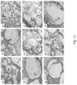
- 238000010186 staining Methods 0.000 description 9
- 239000000919 ceramic Substances 0.000 description 8
- 238000012258 culturing Methods 0.000 description 8
- 210000002889 endothelial cell Anatomy 0.000 description 8
- 239000002121 nanofiber Substances 0.000 description 8
- CURLTUGMZLYLDI-UHFFFAOYSA-N Carbon dioxide Chemical compound O=C=O CURLTUGMZLYLDI-UHFFFAOYSA-N 0.000 description 7
- 230000006698 induction Effects 0.000 description 7
- 238000002054 transplantation Methods 0.000 description 7
- 108091003079 Bovine Serum Albumin Proteins 0.000 description 6
- 241001465754 Metazoa Species 0.000 description 6
- 108010025020 Nerve Growth Factor Proteins 0.000 description 6
- QVGXLLKOCUKJST-UHFFFAOYSA-N atomic oxygen Chemical compound [O] QVGXLLKOCUKJST-UHFFFAOYSA-N 0.000 description 6
- 230000010261 cell growth Effects 0.000 description 6
- 210000001105 femoral artery Anatomy 0.000 description 6
- 230000014509 gene expression Effects 0.000 description 6
- 239000012510 hollow fiber Substances 0.000 description 6
- 230000000670 limiting effect Effects 0.000 description 6
- 229910052760 oxygen Inorganic materials 0.000 description 6
- 239000001301 oxygen Substances 0.000 description 6
- XLYOFNOQVPJJNP-UHFFFAOYSA-N water Substances O XLYOFNOQVPJJNP-UHFFFAOYSA-N 0.000 description 6
- 239000006144 Dulbecco’s modified Eagle's medium Substances 0.000 description 5
- HTTJABKRGRZYRN-UHFFFAOYSA-N Heparin Chemical compound OC1C(NC(=O)C)C(O)OC(COS(O)(=O)=O)C1OC1C(OS(O)(=O)=O)C(O)C(OC2C(C(OS(O)(=O)=O)C(OC3C(C(O)C(O)C(O3)C(O)=O)OS(O)(=O)=O)C(CO)O2)NS(O)(=O)=O)C(C(O)=O)O1 HTTJABKRGRZYRN-UHFFFAOYSA-N 0.000 description 5
- 108010009583 Transforming Growth Factors Proteins 0.000 description 5
- 102000009618 Transforming Growth Factors Human genes 0.000 description 5
- 238000004458 analytical method Methods 0.000 description 5
- YQGOJNYOYNNSMM-UHFFFAOYSA-N eosin Chemical compound [Na+].OC(=O)C1=CC=CC=C1C1=C2C=C(Br)C(=O)C(Br)=C2OC2=C(Br)C(O)=C(Br)C=C21 YQGOJNYOYNNSMM-UHFFFAOYSA-N 0.000 description 5
- 238000002474 experimental method Methods 0.000 description 5
- 229920000669 heparin Polymers 0.000 description 5
- 229960002897 heparin Drugs 0.000 description 5
- 239000002207 metabolite Substances 0.000 description 5
- 210000000056 organ Anatomy 0.000 description 5
- 230000010412 perfusion Effects 0.000 description 5
- 238000001356 surgical procedure Methods 0.000 description 5
- 239000002699 waste material Substances 0.000 description 5
- HEDRZPFGACZZDS-UHFFFAOYSA-N Chloroform Chemical compound ClC(Cl)Cl HEDRZPFGACZZDS-UHFFFAOYSA-N 0.000 description 4
- LFQSCWFLJHTTHZ-UHFFFAOYSA-N Ethanol Chemical compound CCO LFQSCWFLJHTTHZ-UHFFFAOYSA-N 0.000 description 4
- 108090000723 Insulin-Like Growth Factor I Proteins 0.000 description 4
- 102000013275 Somatomedins Human genes 0.000 description 4
- 102100032317 Transcription factor Sp7 Human genes 0.000 description 4
- 238000005273 aeration Methods 0.000 description 4
- 210000004102 animal cell Anatomy 0.000 description 4
- 229910002092 carbon dioxide Inorganic materials 0.000 description 4
- 238000004113 cell culture Methods 0.000 description 4
- 230000004087 circulation Effects 0.000 description 4
- 150000001875 compounds Chemical class 0.000 description 4
- 238000013461 design Methods 0.000 description 4
- 238000011161 development Methods 0.000 description 4
- 230000018109 developmental process Effects 0.000 description 4
- 210000003191 femoral vein Anatomy 0.000 description 4
- 239000012091 fetal bovine serum Substances 0.000 description 4
- 230000006870 function Effects 0.000 description 4
- 239000007789 gas Substances 0.000 description 4
- 238000011081 inoculation Methods 0.000 description 4
- 230000010354 integration Effects 0.000 description 4
- 238000002406 microsurgery Methods 0.000 description 4
- 210000003205 muscle Anatomy 0.000 description 4
- 238000002360 preparation method Methods 0.000 description 4
- 230000035899 viability Effects 0.000 description 4
- 102000004506 Blood Proteins Human genes 0.000 description 3
- 108010017384 Blood Proteins Proteins 0.000 description 3
- 238000002738 Giemsa staining Methods 0.000 description 3
- 102100022373 Homeobox protein DLX-5 Human genes 0.000 description 3
- 101000901627 Homo sapiens Homeobox protein DLX-5 Proteins 0.000 description 3
- 108091006905 Human Serum Albumin Proteins 0.000 description 3
- 102000008100 Human Serum Albumin Human genes 0.000 description 3
- 102000016943 Muramidase Human genes 0.000 description 3
- 108010014251 Muramidase Proteins 0.000 description 3
- 108010062010 N-Acetylmuramoyl-L-alanine Amidase Proteins 0.000 description 3
- 102000015336 Nerve Growth Factor Human genes 0.000 description 3
- 102000007072 Nerve Growth Factors Human genes 0.000 description 3
- 108010073929 Vascular Endothelial Growth Factor A Proteins 0.000 description 3
- 102000005789 Vascular Endothelial Growth Factors Human genes 0.000 description 3
- 108010019530 Vascular Endothelial Growth Factors Proteins 0.000 description 3
- 238000009825 accumulation Methods 0.000 description 3
- 230000033115 angiogenesis Effects 0.000 description 3
- 238000010171 animal model Methods 0.000 description 3
- 230000008901 benefit Effects 0.000 description 3
- 230000024245 cell differentiation Effects 0.000 description 3
- 238000000151 deposition Methods 0.000 description 3
- 230000005686 electrostatic field Effects 0.000 description 3
- 238000005516 engineering process Methods 0.000 description 3
- 210000003709 heart valve Anatomy 0.000 description 3
- 230000001965 increasing effect Effects 0.000 description 3
- 230000033001 locomotion Effects 0.000 description 3
- 229960000274 lysozyme Drugs 0.000 description 3
- 239000004325 lysozyme Substances 0.000 description 3
- 235000010335 lysozyme Nutrition 0.000 description 3
- 238000005259 measurement Methods 0.000 description 3
- 238000010369 molecular cloning Methods 0.000 description 3
- 230000035515 penetration Effects 0.000 description 3
- 108090000765 processed proteins & peptides Proteins 0.000 description 3
- 238000003753 real-time PCR Methods 0.000 description 3
- 230000001105 regulatory effect Effects 0.000 description 3
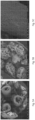
- 238000001878 scanning electron micrograph Methods 0.000 description 3
- 210000002966 serum Anatomy 0.000 description 3
- 210000003491 skin Anatomy 0.000 description 3
- 238000012360 testing method Methods 0.000 description 3
- 102100024506 Bone morphogenetic protein 2 Human genes 0.000 description 2
- 206010053567 Coagulopathies Diseases 0.000 description 2
- 108010071942 Colony-Stimulating Factors Proteins 0.000 description 2
- 102000007644 Colony-Stimulating Factors Human genes 0.000 description 2
- 102000004127 Cytokines Human genes 0.000 description 2
- 108090000695 Cytokines Proteins 0.000 description 2
- KCXVZYZYPLLWCC-UHFFFAOYSA-N EDTA Chemical compound OC(=O)CN(CC(O)=O)CCN(CC(O)=O)CC(O)=O KCXVZYZYPLLWCC-UHFFFAOYSA-N 0.000 description 2
- 102000010834 Extracellular Matrix Proteins Human genes 0.000 description 2
- 108010037362 Extracellular Matrix Proteins Proteins 0.000 description 2
- 108010049003 Fibrinogen Proteins 0.000 description 2
- 102000008946 Fibrinogen Human genes 0.000 description 2
- 102000018233 Fibroblast Growth Factor Human genes 0.000 description 2
- 108050007372 Fibroblast Growth Factor Proteins 0.000 description 2
- 102000003972 Fibroblast growth factor 7 Human genes 0.000 description 2
- 108090000385 Fibroblast growth factor 7 Proteins 0.000 description 2
- WSFSSNUMVMOOMR-UHFFFAOYSA-N Formaldehyde Chemical compound O=C WSFSSNUMVMOOMR-UHFFFAOYSA-N 0.000 description 2
- WQZGKKKJIJFFOK-GASJEMHNSA-N Glucose Natural products OC[C@H]1OC(O)[C@H](O)[C@@H](O)[C@@H]1O WQZGKKKJIJFFOK-GASJEMHNSA-N 0.000 description 2
- DHCLVCXQIBBOPH-UHFFFAOYSA-N Glycerol 2-phosphate Chemical compound OCC(CO)OP(O)(O)=O DHCLVCXQIBBOPH-UHFFFAOYSA-N 0.000 description 2
- 108010017080 Granulocyte Colony-Stimulating Factor Proteins 0.000 description 2
- 102000004269 Granulocyte Colony-Stimulating Factor Human genes 0.000 description 2
- 108010063738 Interleukins Proteins 0.000 description 2
- 102000015696 Interleukins Human genes 0.000 description 2
- 102000007547 Laminin Human genes 0.000 description 2
- 108010085895 Laminin Proteins 0.000 description 2
- 241000699670 Mus sp. Species 0.000 description 2
- 229920003171 Poly (ethylene oxide) Polymers 0.000 description 2
- 239000002202 Polyethylene glycol Substances 0.000 description 2
- 229920000331 Polyhydroxybutyrate Polymers 0.000 description 2
- 108020004511 Recombinant DNA Proteins 0.000 description 2
- PLXBWHJQWKZRKG-UHFFFAOYSA-N Resazurin Chemical compound C1=CC(=O)C=C2OC3=CC(O)=CC=C3[N+]([O-])=C21 PLXBWHJQWKZRKG-UHFFFAOYSA-N 0.000 description 2
- 102000002938 Thrombospondin Human genes 0.000 description 2
- 108060008245 Thrombospondin Proteins 0.000 description 2
- 102000004887 Transforming Growth Factor beta Human genes 0.000 description 2
- 108090001012 Transforming Growth Factor beta Proteins 0.000 description 2
- 102400001320 Transforming growth factor alpha Human genes 0.000 description 2
- 101800004564 Transforming growth factor alpha Proteins 0.000 description 2
- 210000000577 adipose tissue Anatomy 0.000 description 2
- 239000012996 alamarblue reagent Substances 0.000 description 2
- XAGFODPZIPBFFR-UHFFFAOYSA-N aluminium Chemical compound [Al] XAGFODPZIPBFFR-UHFFFAOYSA-N 0.000 description 2
- 229910052782 aluminium Inorganic materials 0.000 description 2
- 150000001413 amino acids Chemical class 0.000 description 2
- 230000003698 anagen phase Effects 0.000 description 2
- WQZGKKKJIJFFOK-VFUOTHLCSA-N beta-D-glucose Chemical compound OC[C@H]1O[C@@H](O)[C@H](O)[C@@H](O)[C@@H]1O WQZGKKKJIJFFOK-VFUOTHLCSA-N 0.000 description 2
- 230000015572 biosynthetic process Effects 0.000 description 2
- 239000006227 byproduct Substances 0.000 description 2
- 238000004364 calculation method Methods 0.000 description 2
- 239000006143 cell culture medium Substances 0.000 description 2
- 230000004663 cell proliferation Effects 0.000 description 2
- 230000035602 clotting Effects 0.000 description 2
- 229940047120 colony stimulating factors Drugs 0.000 description 2
- 210000002808 connective tissue Anatomy 0.000 description 2
- 238000013270 controlled release Methods 0.000 description 2
- 230000001276 controlling effect Effects 0.000 description 2
- 230000008021 deposition Effects 0.000 description 2
- 230000000694 effects Effects 0.000 description 2
- 210000002744 extracellular matrix Anatomy 0.000 description 2
- 239000012894 fetal calf serum Substances 0.000 description 2
- 210000003754 fetus Anatomy 0.000 description 2
- 229940012952 fibrinogen Drugs 0.000 description 2
- 238000001943 fluorescence-activated cell sorting Methods 0.000 description 2
- 230000004907 flux Effects 0.000 description 2
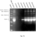
- 238000001502 gel electrophoresis Methods 0.000 description 2
- 239000008103 glucose Substances 0.000 description 2
- 210000001564 haversian system Anatomy 0.000 description 2
- 210000002216 heart Anatomy 0.000 description 2
- FFUAGWLWBBFQJT-UHFFFAOYSA-N hexamethyldisilazane Chemical compound C[Si](C)(C)N[Si](C)(C)C FFUAGWLWBBFQJT-UHFFFAOYSA-N 0.000 description 2
- 238000011534 incubation Methods 0.000 description 2
- 238000001802 infusion Methods 0.000 description 2
- 229940047122 interleukins Drugs 0.000 description 2
- 150000002632 lipids Chemical class 0.000 description 2
- 210000004962 mammalian cell Anatomy 0.000 description 2
- 238000004519 manufacturing process Methods 0.000 description 2
- 239000003550 marker Substances 0.000 description 2
- 239000011159 matrix material Substances 0.000 description 2
- 230000002503 metabolic effect Effects 0.000 description 2
- 230000000921 morphogenic effect Effects 0.000 description 2
- 239000002105 nanoparticle Substances 0.000 description 2
- 230000009818 osteogenic differentiation Effects 0.000 description 2
- 239000012188 paraffin wax Substances 0.000 description 2
- 239000012466 permeate Substances 0.000 description 2
- 239000005015 poly(hydroxybutyrate) Substances 0.000 description 2
- 229920002463 poly(p-dioxanone) polymer Polymers 0.000 description 2
- 239000000622 polydioxanone Substances 0.000 description 2
- 229920001223 polyethylene glycol Polymers 0.000 description 2
- 229920002451 polyvinyl alcohol Polymers 0.000 description 2
- 102000004196 processed proteins & peptides Human genes 0.000 description 2
- 238000011552 rat model Methods 0.000 description 2
- 230000000241 respiratory effect Effects 0.000 description 2
- 238000004626 scanning electron microscopy Methods 0.000 description 2
- 239000000126 substance Substances 0.000 description 2
- 230000004083 survival effect Effects 0.000 description 2
- 239000000725 suspension Substances 0.000 description 2
- ZRKFYGHZFMAOKI-QMGMOQQFSA-N tgfbeta Chemical compound C([C@H](NC(=O)[C@H](C(C)C)NC(=O)CNC(=O)[C@H](CCC(O)=O)NC(=O)[C@H](CCCNC(N)=N)NC(=O)[C@H](CC(N)=O)NC(=O)[C@H](CC(C)C)NC(=O)[C@H]([C@@H](C)O)NC(=O)[C@H](CCC(O)=O)NC(=O)[C@H]([C@@H](C)O)NC(=O)[C@H](CC(C)C)NC(=O)CNC(=O)[C@H](C)NC(=O)[C@H](CO)NC(=O)[C@H](CCC(N)=O)NC(=O)[C@@H](NC(=O)[C@H](C)NC(=O)[C@H](C)NC(=O)[C@@H](NC(=O)[C@H](CC(C)C)NC(=O)[C@@H](N)CCSC)C(C)C)[C@@H](C)CC)C(=O)N[C@@H]([C@@H](C)O)C(=O)N[C@@H](C(C)C)C(=O)N[C@@H](CC=1C=CC=CC=1)C(=O)N[C@@H](C)C(=O)N1[C@@H](CCC1)C(=O)N[C@@H]([C@@H](C)O)C(=O)N[C@@H](CC(N)=O)C(=O)N[C@@H](CCC(O)=O)C(=O)N[C@@H](C)C(=O)N[C@@H](CC=1C=CC=CC=1)C(=O)N[C@@H](CCCNC(N)=N)C(=O)N[C@@H](C)C(=O)N[C@@H](CC(C)C)C(=O)N1[C@@H](CCC1)C(=O)N1[C@@H](CCC1)C(=O)N[C@@H](CCCNC(N)=N)C(=O)N[C@@H](CCC(O)=O)C(=O)N[C@@H](CCCNC(N)=N)C(=O)N[C@@H](CO)C(=O)N[C@@H](CCCNC(N)=N)C(=O)N[C@@H](CC(C)C)C(=O)N[C@@H](CC(C)C)C(O)=O)C1=CC=C(O)C=C1 ZRKFYGHZFMAOKI-QMGMOQQFSA-N 0.000 description 2
- 230000009772 tissue formation Effects 0.000 description 2
- 230000008467 tissue growth Effects 0.000 description 2
- YFHICDDUDORKJB-UHFFFAOYSA-N trimethylene carbonate Chemical compound O=C1OCCCO1 YFHICDDUDORKJB-UHFFFAOYSA-N 0.000 description 2
- 230000004862 vasculogenesis Effects 0.000 description 2
- 231100000747 viability assay Toxicity 0.000 description 2
- 238000003026 viability measurement method Methods 0.000 description 2
- 239000011782 vitamin Substances 0.000 description 2
- 229940088594 vitamin Drugs 0.000 description 2
- 235000013343 vitamin Nutrition 0.000 description 2
- 229930003231 vitamin Natural products 0.000 description 2
- KIUKXJAPPMFGSW-DNGZLQJQSA-N (2S,3S,4S,5R,6R)-6-[(2S,3R,4R,5S,6R)-3-Acetamido-2-[(2S,3S,4R,5R,6R)-6-[(2R,3R,4R,5S,6R)-3-acetamido-2,5-dihydroxy-6-(hydroxymethyl)oxan-4-yl]oxy-2-carboxy-4,5-dihydroxyoxan-3-yl]oxy-5-hydroxy-6-(hydroxymethyl)oxan-4-yl]oxy-3,4,5-trihydroxyoxane-2-carboxylic acid Chemical compound CC(=O)N[C@H]1[C@H](O)O[C@H](CO)[C@@H](O)[C@@H]1O[C@H]1[C@H](O)[C@@H](O)[C@H](O[C@H]2[C@@H]([C@@H](O[C@H]3[C@@H]([C@@H](O)[C@H](O)[C@H](O3)C(O)=O)O)[C@H](O)[C@@H](CO)O2)NC(C)=O)[C@@H](C(O)=O)O1 KIUKXJAPPMFGSW-DNGZLQJQSA-N 0.000 description 1
- NMWKYTGJWUAZPZ-WWHBDHEGSA-N (4S)-4-[[(4R,7S,10S,16S,19S,25S,28S,31R)-31-[[(2S)-2-[[(1R,6R,9S,12S,18S,21S,24S,27S,30S,33S,36S,39S,42R,47R,53S,56S,59S,62S,65S,68S,71S,76S,79S,85S)-47-[[(2S)-2-[[(2S)-4-amino-2-[[(2S)-2-[[(2S)-2-[[(2S)-2-[[(2S)-2-[[(2S)-2-amino-3-methylbutanoyl]amino]-3-methylbutanoyl]amino]-3-hydroxypropanoyl]amino]-3-(1H-imidazol-4-yl)propanoyl]amino]-3-phenylpropanoyl]amino]-4-oxobutanoyl]amino]-3-carboxypropanoyl]amino]-18-(4-aminobutyl)-27,68-bis(3-amino-3-oxopropyl)-36,71,76-tribenzyl-39-(3-carbamimidamidopropyl)-24-(2-carboxyethyl)-21,56-bis(carboxymethyl)-65,85-bis[(1R)-1-hydroxyethyl]-59-(hydroxymethyl)-62,79-bis(1H-imidazol-4-ylmethyl)-9-methyl-33-(2-methylpropyl)-8,11,17,20,23,26,29,32,35,38,41,48,54,57,60,63,66,69,72,74,77,80,83,86-tetracosaoxo-30-propan-2-yl-3,4,44,45-tetrathia-7,10,16,19,22,25,28,31,34,37,40,49,55,58,61,64,67,70,73,75,78,81,84,87-tetracosazatetracyclo[40.31.14.012,16.049,53]heptaoctacontane-6-carbonyl]amino]-3-methylbutanoyl]amino]-7-(3-carbamimidamidopropyl)-25-(hydroxymethyl)-19-[(4-hydroxyphenyl)methyl]-28-(1H-imidazol-4-ylmethyl)-10-methyl-6,9,12,15,18,21,24,27,30-nonaoxo-16-propan-2-yl-1,2-dithia-5,8,11,14,17,20,23,26,29-nonazacyclodotriacontane-4-carbonyl]amino]-5-[[(2S)-1-[[(2S)-1-[[(2S)-3-carboxy-1-[[(2S)-1-[[(2S)-1-[[(1S)-1-carboxyethyl]amino]-4-methyl-1-oxopentan-2-yl]amino]-4-methyl-1-oxopentan-2-yl]amino]-1-oxopropan-2-yl]amino]-1-oxopropan-2-yl]amino]-3-(1H-imidazol-4-yl)-1-oxopropan-2-yl]amino]-5-oxopentanoic acid Chemical compound CC(C)C[C@H](NC(=O)[C@H](CC(C)C)NC(=O)[C@H](CC(O)=O)NC(=O)[C@H](C)NC(=O)[C@H](Cc1c[nH]cn1)NC(=O)[C@H](CCC(O)=O)NC(=O)[C@@H]1CSSC[C@H](NC(=O)[C@@H](NC(=O)[C@@H]2CSSC[C@@H]3NC(=O)[C@H](Cc4ccccc4)NC(=O)[C@H](CCC(N)=O)NC(=O)[C@@H](NC(=O)[C@H](Cc4c[nH]cn4)NC(=O)[C@H](CO)NC(=O)[C@H](CC(O)=O)NC(=O)[C@@H]4CCCN4C(=O)[C@H](CSSC[C@H](NC(=O)[C@@H](NC(=O)CNC(=O)[C@H](Cc4c[nH]cn4)NC(=O)[C@H](Cc4ccccc4)NC3=O)[C@@H](C)O)C(=O)N[C@@H](CCCNC(N)=N)C(=O)N[C@@H](Cc3ccccc3)C(=O)N[C@@H](CC(C)C)C(=O)N[C@@H](C(C)C)C(=O)N[C@@H](CCC(N)=O)C(=O)N[C@@H](CCC(O)=O)C(=O)N[C@@H](CC(O)=O)C(=O)N[C@@H](CCCCN)C(=O)N3CCC[C@H]3C(=O)N[C@@H](C)C(=O)N2)NC(=O)[C@H](CC(O)=O)NC(=O)[C@H](CC(N)=O)NC(=O)[C@H](Cc2ccccc2)NC(=O)[C@H](Cc2c[nH]cn2)NC(=O)[C@H](CO)NC(=O)[C@@H](NC(=O)[C@@H](N)C(C)C)C(C)C)[C@@H](C)O)C(C)C)C(=O)N[C@@H](Cc2c[nH]cn2)C(=O)N[C@@H](CO)C(=O)NCC(=O)N[C@@H](Cc2ccc(O)cc2)C(=O)N[C@@H](C(C)C)C(=O)NCC(=O)N[C@@H](C)C(=O)N[C@@H](CCCNC(N)=N)C(=O)N1)C(=O)N[C@@H](C)C(O)=O NMWKYTGJWUAZPZ-WWHBDHEGSA-N 0.000 description 1
- FHVDTGUDJYJELY-UHFFFAOYSA-N 6-{[2-carboxy-4,5-dihydroxy-6-(phosphanyloxy)oxan-3-yl]oxy}-4,5-dihydroxy-3-phosphanyloxane-2-carboxylic acid Chemical compound O1C(C(O)=O)C(P)C(O)C(O)C1OC1C(C(O)=O)OC(OP)C(O)C1O FHVDTGUDJYJELY-UHFFFAOYSA-N 0.000 description 1
- 102000007469 Actins Human genes 0.000 description 1
- 108010085238 Actins Proteins 0.000 description 1
- 102400000068 Angiostatin Human genes 0.000 description 1
- 108010079709 Angiostatins Proteins 0.000 description 1
- IYMAXBFPHPZYIK-BQBZGAKWSA-N Arg-Gly-Asp Chemical class NC(N)=NCCC[C@H](N)C(=O)NCC(=O)N[C@@H](CC(O)=O)C(O)=O IYMAXBFPHPZYIK-BQBZGAKWSA-N 0.000 description 1
- 108010049931 Bone Morphogenetic Protein 2 Proteins 0.000 description 1
- 108010049870 Bone Morphogenetic Protein 7 Proteins 0.000 description 1
- 102100022544 Bone morphogenetic protein 7 Human genes 0.000 description 1
- 241000283690 Bos taurus Species 0.000 description 1
- 108090000715 Brain-derived neurotrophic factor Proteins 0.000 description 1
- 102000004219 Brain-derived neurotrophic factor Human genes 0.000 description 1
- 102000000905 Cadherin Human genes 0.000 description 1
- 108050007957 Cadherin Proteins 0.000 description 1
- OYPRJOBELJOOCE-UHFFFAOYSA-N Calcium Chemical compound [Ca] OYPRJOBELJOOCE-UHFFFAOYSA-N 0.000 description 1
- 241000282836 Camelus dromedarius Species 0.000 description 1
- 241000283707 Capra Species 0.000 description 1
- OKTJSMMVPCPJKN-UHFFFAOYSA-N Carbon Chemical compound [C] OKTJSMMVPCPJKN-UHFFFAOYSA-N 0.000 description 1
- 244000132059 Carica parviflora Species 0.000 description 1
- 235000014653 Carica parviflora Nutrition 0.000 description 1
- 241000700199 Cavia porcellus Species 0.000 description 1
- 102000019034 Chemokines Human genes 0.000 description 1
- 108010012236 Chemokines Proteins 0.000 description 1
- 229920001661 Chitosan Polymers 0.000 description 1
- 102000012422 Collagen Type I Human genes 0.000 description 1
- 108010022452 Collagen Type I Proteins 0.000 description 1
- 241000699800 Cricetinae Species 0.000 description 1
- 108010014258 Elastin Proteins 0.000 description 1
- 102000016942 Elastin Human genes 0.000 description 1
- 108010044063 Endocrine-Gland-Derived Vascular Endothelial Growth Factor Proteins 0.000 description 1
- 102400001047 Endostatin Human genes 0.000 description 1
- 108010079505 Endostatins Proteins 0.000 description 1
- 108090000790 Enzymes Proteins 0.000 description 1
- 102000004190 Enzymes Human genes 0.000 description 1
- 241000283073 Equus caballus Species 0.000 description 1
- 241000282326 Felis catus Species 0.000 description 1
- 102000003974 Fibroblast growth factor 2 Human genes 0.000 description 1
- 108090000379 Fibroblast growth factor 2 Proteins 0.000 description 1
- 102000034615 Glial cell line-derived neurotrophic factor Human genes 0.000 description 1
- 108091010837 Glial cell line-derived neurotrophic factor Proteins 0.000 description 1
- 229930186217 Glycolipid Natural products 0.000 description 1
- 102000003886 Glycoproteins Human genes 0.000 description 1
- 108090000288 Glycoproteins Proteins 0.000 description 1
- 229920002683 Glycosaminoglycan Polymers 0.000 description 1
- 108090000100 Hepatocyte Growth Factor Proteins 0.000 description 1
- 102100021866 Hepatocyte growth factor Human genes 0.000 description 1
- 101000762366 Homo sapiens Bone morphogenetic protein 2 Proteins 0.000 description 1
- 108060003951 Immunoglobulin Proteins 0.000 description 1
- 238000012404 In vitro experiment Methods 0.000 description 1
- 206010061218 Inflammation Diseases 0.000 description 1
- 108010050904 Interferons Proteins 0.000 description 1
- 102000014150 Interferons Human genes 0.000 description 1
- YQEZLKZALYSWHR-UHFFFAOYSA-N Ketamine Chemical compound C=1C=CC=C(Cl)C=1C1(NC)CCCCC1=O YQEZLKZALYSWHR-UHFFFAOYSA-N 0.000 description 1
- ZDXPYRJPNDTMRX-VKHMYHEASA-N L-glutamine Chemical compound OC(=O)[C@@H](N)CCC(N)=O ZDXPYRJPNDTMRX-VKHMYHEASA-N 0.000 description 1
- 229930182816 L-glutamine Natural products 0.000 description 1
- 108010092277 Leptin Proteins 0.000 description 1
- 102000016267 Leptin Human genes 0.000 description 1
- 102000004895 Lipoproteins Human genes 0.000 description 1
- 108090001030 Lipoproteins Proteins 0.000 description 1
- 102000009571 Macrophage Inflammatory Proteins Human genes 0.000 description 1
- 108010009474 Macrophage Inflammatory Proteins Proteins 0.000 description 1
- 102000029749 Microtubule Human genes 0.000 description 1
- 108091022875 Microtubule Proteins 0.000 description 1
- 241000699666 Mus <mouse, genus> Species 0.000 description 1
- 241000283973 Oryctolagus cuniculus Species 0.000 description 1
- 108090000573 Osteocalcin Proteins 0.000 description 1
- 102000004067 Osteocalcin Human genes 0.000 description 1
- 108010077077 Osteonectin Proteins 0.000 description 1
- 102000009890 Osteonectin Human genes 0.000 description 1
- 101150042788 PROK2 gene Proteins 0.000 description 1
- 241001494479 Pecora Species 0.000 description 1
- 241000009328 Perro Species 0.000 description 1
- 102100040681 Platelet-derived growth factor C Human genes 0.000 description 1
- UQKKDJWFQBNZBJ-UHFFFAOYSA-N Polydin Natural products OC1C(O)C(O)COC1OC1=CC(O)=C(CC(O)C(O2)C=3C=C(O)C(O)=CC=3)C2=C1 UQKKDJWFQBNZBJ-UHFFFAOYSA-N 0.000 description 1
- 102100040126 Prokineticin-1 Human genes 0.000 description 1
- 239000004792 Prolene Substances 0.000 description 1
- 108010067787 Proteoglycans Proteins 0.000 description 1
- 102000016611 Proteoglycans Human genes 0.000 description 1
- 102000003800 Selectins Human genes 0.000 description 1
- 108090000184 Selectins Proteins 0.000 description 1
- 206010061363 Skeletal injury Diseases 0.000 description 1
- 108010043267 Sp7 Transcription Factor Proteins 0.000 description 1
- 241000282898 Sus scrofa Species 0.000 description 1
- 102000007000 Tenascin Human genes 0.000 description 1
- 108010008125 Tenascin Proteins 0.000 description 1
- 108090000190 Thrombin Proteins 0.000 description 1
- 208000007536 Thrombosis Diseases 0.000 description 1
- 108060008682 Tumor Necrosis Factor Proteins 0.000 description 1
- 108010031318 Vitronectin Proteins 0.000 description 1
- 102100035140 Vitronectin Human genes 0.000 description 1
- JCUALBCUIPQRGI-YTQCUDPKSA-H [O-]P([O-])(OC(C(O[C@@H]1[C@H](CO)O)=O)=C1O)=O.[O-]P([O-])(OC(C(O[C@@H]1[C@H](CO)O)=O)=C1O)=O.[O-]P([O-])(OC(C(O[C@@H]1[C@H](CO)O)=O)=C1O)=O.OC[C@@H]([C@H](C(O)=C1OP(O)(O)=O)OC1=O)O.OC[C@@H]([C@H](C(O)=C1OP(O)(O)=O)OC1=O)O.OC[C@@H]([C@H](C(O)=C1OP(O)(O)=O)OC1=O)O.[Mg+2].[Mg+2].[Mg+2] Chemical compound [O-]P([O-])(OC(C(O[C@@H]1[C@H](CO)O)=O)=C1O)=O.[O-]P([O-])(OC(C(O[C@@H]1[C@H](CO)O)=O)=C1O)=O.[O-]P([O-])(OC(C(O[C@@H]1[C@H](CO)O)=O)=C1O)=O.OC[C@@H]([C@H](C(O)=C1OP(O)(O)=O)OC1=O)O.OC[C@@H]([C@H](C(O)=C1OP(O)(O)=O)OC1=O)O.OC[C@@H]([C@H](C(O)=C1OP(O)(O)=O)OC1=O)O.[Mg+2].[Mg+2].[Mg+2] JCUALBCUIPQRGI-YTQCUDPKSA-H 0.000 description 1
- 230000003187 abdominal effect Effects 0.000 description 1
- 230000005856 abnormality Effects 0.000 description 1
- 229940072056 alginate Drugs 0.000 description 1
- 229920000615 alginic acid Polymers 0.000 description 1
- 235000010443 alginic acid Nutrition 0.000 description 1
- PNEYBMLMFCGWSK-UHFFFAOYSA-N aluminium oxide Inorganic materials [O-2].[O-2].[O-2].[Al+3].[Al+3] PNEYBMLMFCGWSK-UHFFFAOYSA-N 0.000 description 1
- 230000019552 anatomical structure morphogenesis Effects 0.000 description 1
- 239000002870 angiogenesis inducing agent Substances 0.000 description 1
- 230000002491 angiogenic effect Effects 0.000 description 1
- 239000003242 anti bacterial agent Substances 0.000 description 1
- 229940088710 antibiotic agent Drugs 0.000 description 1
- 239000000427 antigen Substances 0.000 description 1
- 102000036639 antigens Human genes 0.000 description 1
- 108091007433 antigens Proteins 0.000 description 1
- 210000000709 aorta Anatomy 0.000 description 1
- 239000012736 aqueous medium Substances 0.000 description 1
- 108010072041 arginyl-glycyl-aspartic acid Proteins 0.000 description 1
- FZCSTZYAHCUGEM-UHFFFAOYSA-N aspergillomarasmine B Natural products OC(=O)CNC(C(O)=O)CNC(C(O)=O)CC(O)=O FZCSTZYAHCUGEM-UHFFFAOYSA-N 0.000 description 1
- 210000001142 back Anatomy 0.000 description 1
- 239000000560 biocompatible material Substances 0.000 description 1
- 239000012620 biological material Substances 0.000 description 1
- 230000000740 bleeding effect Effects 0.000 description 1
- 230000000903 blocking effect Effects 0.000 description 1
- 230000008081 blood perfusion Effects 0.000 description 1
- 230000036770 blood supply Effects 0.000 description 1
- 230000008468 bone growth Effects 0.000 description 1
- 210000002805 bone matrix Anatomy 0.000 description 1
- 229940077737 brain-derived neurotrophic factor Drugs 0.000 description 1
- 230000005587 bubbling Effects 0.000 description 1
- 239000011575 calcium Substances 0.000 description 1
- 229910052791 calcium Inorganic materials 0.000 description 1
- 150000001720 carbohydrates Chemical class 0.000 description 1
- 235000014633 carbohydrates Nutrition 0.000 description 1
- 229910052799 carbon Inorganic materials 0.000 description 1
- 239000001569 carbon dioxide Substances 0.000 description 1
- 210000005242 cardiac chamber Anatomy 0.000 description 1
- 210000000845 cartilage Anatomy 0.000 description 1
- 230000015556 catabolic process Effects 0.000 description 1
- 230000003833 cell viability Effects 0.000 description 1
- 230000001413 cellular effect Effects 0.000 description 1
- 230000008859 change Effects 0.000 description 1
- 238000012512 characterization method Methods 0.000 description 1
- 238000006243 chemical reaction Methods 0.000 description 1
- 238000003501 co-culture Methods 0.000 description 1
- 239000011248 coating agent Substances 0.000 description 1
- 238000000576 coating method Methods 0.000 description 1
- 229910052681 coesite Inorganic materials 0.000 description 1
- 230000001427 coherent effect Effects 0.000 description 1
- 239000012141 concentrate Substances 0.000 description 1
- 230000002596 correlated effect Effects 0.000 description 1
- 229910052593 corundum Inorganic materials 0.000 description 1
- 229910052906 cristobalite Inorganic materials 0.000 description 1
- 210000004748 cultured cell Anatomy 0.000 description 1
- 230000006378 damage Effects 0.000 description 1
- 238000006731 degradation reaction Methods 0.000 description 1
- 230000001419 dependent effect Effects 0.000 description 1
- UREBDLICKHMUKA-CXSFZGCWSA-N dexamethasone Chemical compound C1CC2=CC(=O)C=C[C@]2(C)[C@]2(F)[C@@H]1[C@@H]1C[C@@H](C)[C@@](C(=O)CO)(O)[C@@]1(C)C[C@@H]2O UREBDLICKHMUKA-CXSFZGCWSA-N 0.000 description 1
- 229960003957 dexamethasone Drugs 0.000 description 1
- 230000003292 diminished effect Effects 0.000 description 1
- 201000010099 disease Diseases 0.000 description 1
- 208000037265 diseases, disorders, signs and symptoms Diseases 0.000 description 1
- 239000003814 drug Substances 0.000 description 1
- 230000002526 effect on cardiovascular system Effects 0.000 description 1
- 229920002549 elastin Polymers 0.000 description 1
- 239000003792 electrolyte Substances 0.000 description 1
- 210000002257 embryonic structure Anatomy 0.000 description 1
- 229940088598 enzyme Drugs 0.000 description 1
- 229920006332 epoxy adhesive Polymers 0.000 description 1
- 229920006335 epoxy glue Polymers 0.000 description 1
- 238000011156 evaluation Methods 0.000 description 1
- 230000005284 excitation Effects 0.000 description 1
- 239000003925 fat Substances 0.000 description 1
- 210000002950 fibroblast Anatomy 0.000 description 1
- 102000034240 fibrous proteins Human genes 0.000 description 1
- 108091005899 fibrous proteins Proteins 0.000 description 1
- 239000012737 fresh medium Substances 0.000 description 1
- 239000000499 gel Substances 0.000 description 1
- 238000010353 genetic engineering Methods 0.000 description 1
- 230000002518 glial effect Effects 0.000 description 1
- 239000003292 glue Substances 0.000 description 1
- PCHJSUWPFVWCPO-UHFFFAOYSA-N gold Chemical compound [Au] PCHJSUWPFVWCPO-UHFFFAOYSA-N 0.000 description 1
- 239000010931 gold Substances 0.000 description 1
- 229910052737 gold Inorganic materials 0.000 description 1
- 230000036541 health Effects 0.000 description 1
- 238000007490 hematoxylin and eosin (H&E) staining Methods 0.000 description 1
- 229940088597 hormone Drugs 0.000 description 1
- 239000005556 hormone Substances 0.000 description 1
- 229920002674 hyaluronan Polymers 0.000 description 1
- 229960003160 hyaluronic acid Drugs 0.000 description 1
- 210000001822 immobilized cell Anatomy 0.000 description 1
- 238000003018 immunoassay Methods 0.000 description 1
- 102000018358 immunoglobulin Human genes 0.000 description 1
- 229940072221 immunoglobulins Drugs 0.000 description 1
- 239000007943 implant Substances 0.000 description 1
- 230000001976 improved effect Effects 0.000 description 1
- 230000006872 improvement Effects 0.000 description 1
- 238000010348 incorporation Methods 0.000 description 1
- 208000015181 infectious disease Diseases 0.000 description 1
- 230000004054 inflammatory process Effects 0.000 description 1
- 230000002401 inhibitory effect Effects 0.000 description 1
- 229910010272 inorganic material Inorganic materials 0.000 description 1
- 239000011147 inorganic material Substances 0.000 description 1
- 102000006495 integrins Human genes 0.000 description 1
- 108010044426 integrins Proteins 0.000 description 1
- 230000003993 interaction Effects 0.000 description 1
- 230000008611 intercellular interaction Effects 0.000 description 1
- 229940047124 interferons Drugs 0.000 description 1
- 230000000968 intestinal effect Effects 0.000 description 1
- 230000003834 intracellular effect Effects 0.000 description 1
- 210000004153 islets of langerhan Anatomy 0.000 description 1
- 238000005304 joining Methods 0.000 description 1
- 229960003299 ketamine Drugs 0.000 description 1
- 210000003734 kidney Anatomy 0.000 description 1
- NRYBAZVQPHGZNS-ZSOCWYAHSA-N leptin Chemical compound O=C([C@H](CO)NC(=O)[C@H](CC(C)C)NC(=O)[C@H](CC(O)=O)NC(=O)[C@H](CC(C)C)NC(=O)[C@H](CCC(N)=O)NC(=O)[C@H](CC=1C2=CC=CC=C2NC=1)NC(=O)[C@H](CC(C)C)NC(=O)[C@@H](NC(=O)[C@H](CC(O)=O)NC(=O)[C@H](CCC(N)=O)NC(=O)[C@H](CC(C)C)NC(=O)[C@H](CO)NC(=O)CNC(=O)[C@H](CCC(N)=O)NC(=O)[C@@H](N)CC(C)C)CCSC)N1CCC[C@H]1C(=O)NCC(=O)N[C@@H](CS)C(O)=O NRYBAZVQPHGZNS-ZSOCWYAHSA-N 0.000 description 1
- 229940039781 leptin Drugs 0.000 description 1
- 208000032839 leukemia Diseases 0.000 description 1
- 210000005228 liver tissue Anatomy 0.000 description 1
- 230000007774 longterm Effects 0.000 description 1
- 210000002540 macrophage Anatomy 0.000 description 1
- 230000004060 metabolic process Effects 0.000 description 1
- 150000001247 metal acetylides Chemical class 0.000 description 1
- 230000002906 microbiologic effect Effects 0.000 description 1
- 239000003658 microfiber Substances 0.000 description 1
- 210000004688 microtubule Anatomy 0.000 description 1
- 210000004088 microvessel Anatomy 0.000 description 1
- 230000003278 mimic effect Effects 0.000 description 1
- 150000002772 monosaccharides Chemical class 0.000 description 1
- 230000000877 morphologic effect Effects 0.000 description 1
- 210000000663 muscle cell Anatomy 0.000 description 1
- 230000003387 muscular Effects 0.000 description 1
- 239000013642 negative control Substances 0.000 description 1
- 210000002569 neuron Anatomy 0.000 description 1
- 239000002858 neurotransmitter agent Substances 0.000 description 1
- 230000000508 neurotrophic effect Effects 0.000 description 1
- 230000007935 neutral effect Effects 0.000 description 1
- 150000004767 nitrides Chemical class 0.000 description 1
- 231100000252 nontoxic Toxicity 0.000 description 1
- 230000003000 nontoxic effect Effects 0.000 description 1
- 238000007899 nucleic acid hybridization Methods 0.000 description 1
- 108020004707 nucleic acids Proteins 0.000 description 1
- 102000039446 nucleic acids Human genes 0.000 description 1
- 150000007523 nucleic acids Chemical class 0.000 description 1
- 239000002773 nucleotide Substances 0.000 description 1
- 125000003729 nucleotide group Chemical group 0.000 description 1
- 239000002674 ointment Substances 0.000 description 1
- 238000002515 oligonucleotide synthesis Methods 0.000 description 1
- 229920001542 oligosaccharide Polymers 0.000 description 1
- 150000002482 oligosaccharides Chemical class 0.000 description 1
- 230000003287 optical effect Effects 0.000 description 1
- 229940094443 oxytocics prostaglandins Drugs 0.000 description 1
- 210000004738 parenchymal cell Anatomy 0.000 description 1
- 229920003023 plastic Polymers 0.000 description 1
- 239000004033 plastic Substances 0.000 description 1
- 108010017992 platelet-derived growth factor C Proteins 0.000 description 1
- 238000007747 plating Methods 0.000 description 1
- 108091033319 polynucleotide Proteins 0.000 description 1
- 102000040430 polynucleotide Human genes 0.000 description 1
- 239000002157 polynucleotide Substances 0.000 description 1
- 229920001184 polypeptide Polymers 0.000 description 1
- 239000013641 positive control Substances 0.000 description 1
- 150000003180 prostaglandins Chemical class 0.000 description 1
- 238000012514 protein characterization Methods 0.000 description 1
- 238000001742 protein purification Methods 0.000 description 1
- 230000002685 pulmonary effect Effects 0.000 description 1
- 238000011002 quantification Methods 0.000 description 1
- 230000009467 reduction Effects 0.000 description 1
- 230000002829 reductive effect Effects 0.000 description 1
- 210000005084 renal tissue Anatomy 0.000 description 1
- 230000033458 reproduction Effects 0.000 description 1
- 230000004044 response Effects 0.000 description 1
- 230000000717 retained effect Effects 0.000 description 1
- 230000002441 reversible effect Effects 0.000 description 1
- 230000033764 rhythmic process Effects 0.000 description 1
- 150000003839 salts Chemical class 0.000 description 1
- 238000005070 sampling Methods 0.000 description 1
- 229910052710 silicon Inorganic materials 0.000 description 1
- 239000010703 silicon Substances 0.000 description 1
- 239000000377 silicon dioxide Substances 0.000 description 1
- VYPSYNLAJGMNEJ-UHFFFAOYSA-N silicon dioxide Inorganic materials O=[Si]=O VYPSYNLAJGMNEJ-UHFFFAOYSA-N 0.000 description 1
- 230000009645 skeletal growth Effects 0.000 description 1
- 210000004927 skin cell Anatomy 0.000 description 1
- 239000002904 solvent Substances 0.000 description 1
- 238000000935 solvent evaporation Methods 0.000 description 1
- 241000894007 species Species 0.000 description 1
- 238000012453 sprague-dawley rat model Methods 0.000 description 1
- 230000001954 sterilising effect Effects 0.000 description 1
- 238000004659 sterilization and disinfection Methods 0.000 description 1
- 229910052682 stishovite Inorganic materials 0.000 description 1
- 239000004575 stone Substances 0.000 description 1
- 150000003568 thioethers Chemical class 0.000 description 1
- 229960004072 thrombin Drugs 0.000 description 1
- 239000011573 trace mineral Substances 0.000 description 1
- 235000013619 trace mineral Nutrition 0.000 description 1
- 238000013518 transcription Methods 0.000 description 1
- 230000035897 transcription Effects 0.000 description 1
- 238000013519 translation Methods 0.000 description 1
- 229910052905 tridymite Inorganic materials 0.000 description 1
- 102000003390 tumor necrosis factor Human genes 0.000 description 1
- 210000005166 vasculature Anatomy 0.000 description 1
- 238000009736 wetting Methods 0.000 description 1
- BPICBUSOMSTKRF-UHFFFAOYSA-N xylazine Chemical compound CC1=CC=CC(C)=C1NC1=NCCCS1 BPICBUSOMSTKRF-UHFFFAOYSA-N 0.000 description 1
- 229960001600 xylazine Drugs 0.000 description 1
- 229910001845 yogo sapphire Inorganic materials 0.000 description 1
Images


Classifications
-
- A—HUMAN NECESSITIES
- A61—MEDICAL OR VETERINARY SCIENCE; HYGIENE
- A61L—METHODS OR APPARATUS FOR STERILISING MATERIALS OR OBJECTS IN GENERAL; DISINFECTION, STERILISATION OR DEODORISATION OF AIR; CHEMICAL ASPECTS OF BANDAGES, DRESSINGS, ABSORBENT PADS OR SURGICAL ARTICLES; MATERIALS FOR BANDAGES, DRESSINGS, ABSORBENT PADS OR SURGICAL ARTICLES
- A61L27/00—Materials for grafts or prostheses or for coating grafts or prostheses
- A61L27/36—Materials for grafts or prostheses or for coating grafts or prostheses containing ingredients of undetermined constitution or reaction products thereof, e.g. transplant tissue, natural bone, extracellular matrix
- A61L27/38—Materials for grafts or prostheses or for coating grafts or prostheses containing ingredients of undetermined constitution or reaction products thereof, e.g. transplant tissue, natural bone, extracellular matrix containing added animal cells
- A61L27/3804—Materials for grafts or prostheses or for coating grafts or prostheses containing ingredients of undetermined constitution or reaction products thereof, e.g. transplant tissue, natural bone, extracellular matrix containing added animal cells characterised by specific cells or progenitors thereof, e.g. fibroblasts, connective tissue cells, kidney cells
-
- A—HUMAN NECESSITIES
- A61—MEDICAL OR VETERINARY SCIENCE; HYGIENE
- A61F—FILTERS IMPLANTABLE INTO BLOOD VESSELS; PROSTHESES; DEVICES PROVIDING PATENCY TO, OR PREVENTING COLLAPSING OF, TUBULAR STRUCTURES OF THE BODY, e.g. STENTS; ORTHOPAEDIC, NURSING OR CONTRACEPTIVE DEVICES; FOMENTATION; TREATMENT OR PROTECTION OF EYES OR EARS; BANDAGES, DRESSINGS OR ABSORBENT PADS; FIRST-AID KITS
- A61F2/00—Filters implantable into blood vessels; Prostheses, i.e. artificial substitutes or replacements for parts of the body; Appliances for connecting them with the body; Devices providing patency to, or preventing collapsing of, tubular structures of the body, e.g. stents
- A61F2/02—Prostheses implantable into the body
- A61F2/04—Hollow or tubular parts of organs, e.g. bladders, tracheae, bronchi or bile ducts
- A61F2/06—Blood vessels
-
- A—HUMAN NECESSITIES
- A61—MEDICAL OR VETERINARY SCIENCE; HYGIENE
- A61L—METHODS OR APPARATUS FOR STERILISING MATERIALS OR OBJECTS IN GENERAL; DISINFECTION, STERILISATION OR DEODORISATION OF AIR; CHEMICAL ASPECTS OF BANDAGES, DRESSINGS, ABSORBENT PADS OR SURGICAL ARTICLES; MATERIALS FOR BANDAGES, DRESSINGS, ABSORBENT PADS OR SURGICAL ARTICLES
- A61L27/00—Materials for grafts or prostheses or for coating grafts or prostheses
- A61L27/40—Composite materials, i.e. containing one material dispersed in a matrix of the same or different material
- A61L27/44—Composite materials, i.e. containing one material dispersed in a matrix of the same or different material having a macromolecular matrix
- A61L27/446—Composite materials, i.e. containing one material dispersed in a matrix of the same or different material having a macromolecular matrix with other specific inorganic fillers other than those covered by A61L27/443 or A61L27/46
-
- A—HUMAN NECESSITIES
- A61—MEDICAL OR VETERINARY SCIENCE; HYGIENE
- A61L—METHODS OR APPARATUS FOR STERILISING MATERIALS OR OBJECTS IN GENERAL; DISINFECTION, STERILISATION OR DEODORISATION OF AIR; CHEMICAL ASPECTS OF BANDAGES, DRESSINGS, ABSORBENT PADS OR SURGICAL ARTICLES; MATERIALS FOR BANDAGES, DRESSINGS, ABSORBENT PADS OR SURGICAL ARTICLES
- A61L27/00—Materials for grafts or prostheses or for coating grafts or prostheses
- A61L27/40—Composite materials, i.e. containing one material dispersed in a matrix of the same or different material
- A61L27/44—Composite materials, i.e. containing one material dispersed in a matrix of the same or different material having a macromolecular matrix
- A61L27/46—Composite materials, i.e. containing one material dispersed in a matrix of the same or different material having a macromolecular matrix with phosphorus-containing inorganic fillers
-
- A—HUMAN NECESSITIES
- A61—MEDICAL OR VETERINARY SCIENCE; HYGIENE
- A61L—METHODS OR APPARATUS FOR STERILISING MATERIALS OR OBJECTS IN GENERAL; DISINFECTION, STERILISATION OR DEODORISATION OF AIR; CHEMICAL ASPECTS OF BANDAGES, DRESSINGS, ABSORBENT PADS OR SURGICAL ARTICLES; MATERIALS FOR BANDAGES, DRESSINGS, ABSORBENT PADS OR SURGICAL ARTICLES
- A61L27/00—Materials for grafts or prostheses or for coating grafts or prostheses
- A61L27/50—Materials characterised by their function or physical properties, e.g. injectable or lubricating compositions, shape-memory materials, surface modified materials
- A61L27/54—Biologically active materials, e.g. therapeutic substances
-
- A—HUMAN NECESSITIES
- A61—MEDICAL OR VETERINARY SCIENCE; HYGIENE
- A61L—METHODS OR APPARATUS FOR STERILISING MATERIALS OR OBJECTS IN GENERAL; DISINFECTION, STERILISATION OR DEODORISATION OF AIR; CHEMICAL ASPECTS OF BANDAGES, DRESSINGS, ABSORBENT PADS OR SURGICAL ARTICLES; MATERIALS FOR BANDAGES, DRESSINGS, ABSORBENT PADS OR SURGICAL ARTICLES
- A61L27/00—Materials for grafts or prostheses or for coating grafts or prostheses
- A61L27/50—Materials characterised by their function or physical properties, e.g. injectable or lubricating compositions, shape-memory materials, surface modified materials
- A61L27/56—Porous materials, e.g. foams or sponges
-
- A—HUMAN NECESSITIES
- A61—MEDICAL OR VETERINARY SCIENCE; HYGIENE
- A61L—METHODS OR APPARATUS FOR STERILISING MATERIALS OR OBJECTS IN GENERAL; DISINFECTION, STERILISATION OR DEODORISATION OF AIR; CHEMICAL ASPECTS OF BANDAGES, DRESSINGS, ABSORBENT PADS OR SURGICAL ARTICLES; MATERIALS FOR BANDAGES, DRESSINGS, ABSORBENT PADS OR SURGICAL ARTICLES
- A61L27/00—Materials for grafts or prostheses or for coating grafts or prostheses
- A61L27/50—Materials characterised by their function or physical properties, e.g. injectable or lubricating compositions, shape-memory materials, surface modified materials
- A61L27/58—Materials at least partially resorbable by the body
-
- C—CHEMISTRY; METALLURGY
- C12—BIOCHEMISTRY; BEER; SPIRITS; WINE; VINEGAR; MICROBIOLOGY; ENZYMOLOGY; MUTATION OR GENETIC ENGINEERING
- C12N—MICROORGANISMS OR ENZYMES; COMPOSITIONS THEREOF; PROPAGATING, PRESERVING, OR MAINTAINING MICROORGANISMS; MUTATION OR GENETIC ENGINEERING; CULTURE MEDIA
- C12N5/00—Undifferentiated human, animal or plant cells, e.g. cell lines; Tissues; Cultivation or maintenance thereof; Culture media therefor
- C12N5/06—Animal cells or tissues; Human cells or tissues
- C12N5/0602—Vertebrate cells
- C12N5/0652—Cells of skeletal and connective tissues; Mesenchyme
-
- A—HUMAN NECESSITIES
- A61—MEDICAL OR VETERINARY SCIENCE; HYGIENE
- A61L—METHODS OR APPARATUS FOR STERILISING MATERIALS OR OBJECTS IN GENERAL; DISINFECTION, STERILISATION OR DEODORISATION OF AIR; CHEMICAL ASPECTS OF BANDAGES, DRESSINGS, ABSORBENT PADS OR SURGICAL ARTICLES; MATERIALS FOR BANDAGES, DRESSINGS, ABSORBENT PADS OR SURGICAL ARTICLES
- A61L2430/00—Materials or treatment for tissue regeneration
- A61L2430/02—Materials or treatment for tissue regeneration for reconstruction of bones; weight-bearing implants
Definitions
- the present invention relates to the field of tissue engineering, and more particularly to the use of synthetic scaffold for the preparation of prosthetic implants.
- Tissue engineering techniques generally require the use of a scaffold as a three-dimensional template for initial cell attachment and subsequent tissue formation.
- scaffold design is one of the most important aspects of tissue engineering. Appropriate selection of a scaffold is a key factor in the process of producing a viable and clinically relevant engineered tissue.
- a scaffold is expected to possess the following characteristics for use in tissue engineering: (i) a three-dimensional porous structure that allows cell/tissue growth and flow transport of nutrients and metabolic waste; (ii) biodegradable or bioresorbable with a controllable degradation and resorption rate to match cell/tissue growth in vitro and/or in vivo; (iii) conducive surface chemistry for cell attachment, proliferation, and differentiation; (iv) mechanical properties to match those of the tissues at the site of implantation; and (v) process ability to form a variety of shapes and sizes for various applications.
- Tissue vascularization is essential for delivery of nutrients (amino acids, glucose and oxygen) to the tissue and clearance of the metabolism byproducts from the tissue.
- nutrients amino acids, glucose and oxygen
- Numerous techniques for development of vascularized tissue have recently emerged and are classified into two major categories: (a) vasculogenesis and angiogenesis-based techniques and (b) prevascularization-based techniques.
- the former are characterized by the ingrowth of newly formed blood vessels from the host microvasculature into the implanted engineered tissue and includes (1) micropatterning of vascular morphogenesis, (2) use of functionalized biomaterials to promote vasculogenisis and angiogenesis, (3) use of growth factor gradients and (4) co-culture of multiple cell types and control of cell-cell interactions.
- micropatterning of vascular morphogenesis (2) use of functionalized biomaterials to promote vasculogenisis and angiogenesis, (3) use of growth factor gradients and (4) co-culture of multiple cell types and control of cell-cell interactions.
- the prevascularization-based techniques are founded on generating of preformed microvascular networks within tissue constructs prior to their implantation, which later further develop and interconnect with host blood vessels at the implantation site.
- the key advantage of these techniques is the capacity for immediate blood perfusion within the constructs upon implantation, which boosts the proliferation and growth of the cells.
- clinical use of engineered tissues and tissue substitutes is still largely restricted to avascular or thin tissues, and the marked progress achieved in small-scale tissue engineering applications in vitro was ultimately stalled due to the lack of vascular perfusion when scaled up to a sizes relevant for implantation and disease treatment.
- the invention provides a scaffold comprising:
- the scaffold further comprises a plurality of fibers having a diameter range of 0.5-1 0 micrometers.
- the plurality of fibers is dispersed upon a portion of each of said plurality of porous elongated microtubes and wherein a distance between adjacent fibers of the plurality of fibers range between 20 micrometers and 300 micrometers.
- the scaffold further comprises a plurality of bioactive particles embedded in between said plurality of fibers. In some embodiments, the scaffold further comprises a plurality of bioactive particles embedded in between said plurality of fibers and at least a portion of said porous elongated microtubes. In some embodiments, the bioactive particles have a range of 200-1500 micrometers in diameter.
- the plurality of bioactive particles comprises one or more type of osteoconductive particles.
- the one or more types of the osteoconductive particles are selected from the group consisting of: calcium carbonate, hydroxyapatite (HA), demineralized bone material, morselized bone graft, cortical cancellous allograft, cortical cancellous autograft, cortical cancellous xenograft, tricalcium phosphate, corraline mineral and calcium sulfate.
- the particles comprise hydroxylapatite (HA) and calcium carbonate.
- the scaffold is printed, molded, casted, polymerized, or electrospun.
- at least one of said inlet tube, said outlet tube are electrospun tubes.
- said plurality of fibers are electrospun fibers.
- the electrospun tubes or fibers comprise a polymer (or are formed from a polymeric solution) selected from the group consisting of: biodegradable polymers, non-biodegradable polymers and a combination thereof.
- the polymer is selected from the group consisting of: polycaprolactone (PCL), polylactic acid (PLA), polyglycolic acid (PGA), and poly(Lactide-co-Glycolide) (PLGA), poly(orthoester), a poly(phosphazene), poly(or polycaprolactone, polyamide, polysaccharide, albumine and collagen.
- the inlet tube and the outlet tube have, independently, an inner diameter of range of 2,000-1 0,000 micrometers.
- the inlet tube and the outlet tube have, independently, a wall thickness range of 50-2,000 micrometers.
- the plurality of porous elongated microtubes have a wall thickness range of 0.5-50 micrometers.
- an average diameter of a pore of the plurality of porous elongated m icrotubes is 0.1-5 micrometers.
- the scaffold further comprises at least one agent for promoting cell adhesion, colonization, proliferation and/or differentiation. In some embodiments, the scaffold further comprises at least one agent for promoting cell adhesion selected from the group consisting of: gelatin, fibrin, fibronectin and collagen.
- the scaffold further comprises a plurality of cells. In some embodiments, the scaffold further comprises a plurality of cells seeded on and/or within the plurality of fibers. In some embodiments, the scaffold is adapted for cellular growth.
- the plurality of cells is selected from the group consisting of: adipose-derived stem cells, mesenchymal cells, mesenchymal stem cells, vascular smooth muscle cells, adipogenic cells, osteoprogenitors cells, osteoblasts, osteocytes, chondroblasts, chondrocytes and osteoclasts, endothelial progenitor cells, hematopoietic progenitor cells, micro vascular endothelial cells and macro vascular endothelial cells, beta cells, hepatocytes and a combination thereof.
- the invention provides a method of producing a tissue, the method comprising:
- the scaffold further comprises a plurality of fibers dispersed upon each of said plurality of porous elongated microtubes and wherein a distance between adjacent fibers of the plurality of fibers ranges between 20 micrometers and 300 micrometers.
- the cells are seeded on and/or within said plurality of fibers.
- the tissue is suitable for being implanted into a subject in need thereof.
- the inlet and the outlet of the scaffold is suitable for being surgically connected to a vascular system of a subject in need thereof, thereby providing fluid communication between the subject's vascular system and said scaffold.
- the cells are selected from the group consisting of: adipose-derived stem cells, mesenchymal cells, mesenchymal stem cells, vascular smooth muscle cells, adipogenic cells, osteoprogenitors cells, osteoblasts, osteocytes, chondroblasts, chondrocytes and osteoclasts, endothelial progenitor cells, hematopoietic progenitor cells, micro vascular endothelial cells and macro vascular endothelial cells, beta cells, hepatocytes and a combination thereof.
- the scaffold further comprises plurality of bioactive particles embedded in between said plurality of fibers.
- the present invention in some embodiments, provides a 3-dimensional (3D) scaffold that supports growth of cells in a tissue construct, the scaffold comprises a porous tubular system that serves as a built-in vascular system.
- the invention provides a scaffold comprising at least one inlet tube; at least one outlet tube; and a plurality of porous elongated microtubes, wherein each one of said porous elongated microtube has an inner diameter of 5-100 micrometers, and wherein said plurality of elongated microtubes extend from said at least one inlet tube to said at least one outlet tube and is in fluid communication thereto.
- the scaffold provides therein a tubular system facilitating transport of nutrients, gases and metabolites from liquid flux within the tubular system through the pores to cells attached thereto.
- the scaffold's tubular system facilitates transport of by-products of metabolites from the cells.
- the present invention is based in part on the finding that the scaffold of the invention serves as an adequate extracellular matrix (ECM) for cell integration, attachment, proliferation, growth and differentiation as a result of its structure.
- ECM extracellular matrix
- the scaffold may bear features required for effective bone-tissue engineered constructs and is characterized by osteoconductiveness that induces mesenchymal stem cells (MSC) differentiation into bone-forming cells.
- the scaffold can serve as a bioreactor system providing appropriate growth conditions for MSC proliferation and differentiation into bone-forming cells in vitro and for their subsequent development into bone structure in vivo after anastomosis with host blood vessels.
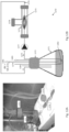
- Fig. 1A is a schematic illustration of a scaffold 100 according to an embodiment of the invention.
- Scaffold 100 comprises an inlet tube 102 which is fluidly-connected to plurality of porous elongated microtubes 104 which extend in fluid communication to an outlet tube 106.
- inlet tube 102 may consist of plurality of inlet tubes such as inlet tubes 102a, 102b, 102c.
- outlet tube 106 may consist of plurality of inlet tubes such as inlet tubes 106a, 106b, 106c.
- Fig. 1B is an enlarged view of a section of porous elongated microtubes 104.
- a plurality of fibers 108 that may serve as a release system of angiogenic/ growth factors are dispersed upon porous elongated microtubes 104.
- bioactive particles 110 e.g., osteoconductive particles
- a plurality of cells 112 may be seeded within plurality of fibers 108.
- plurality of cells may include bone forming cells.
- the wide arrow depicts the flow of blood within porous elongated microtubes 104 and narrow arrows depict the flow of nutrients and oxygen (O 2 ) from porous elongated microtubes 104 to plurality of cells 112.
- Figs 1C-D illustrates forming of cell tissue upon porous elongated microtubes 104.
- the present invention provides a scaffold comprising: at least one inlet tube; at least one outlet tube; and a plurality of porous elongated electrospun microtubes, wherein each one of said porous elongated microtube has an inner diameter of 5-100 micrometers, and wherein said plurality of elongated microtubes extend from said at least one inlet tube to said at least one outlet tube and is in fluid communication thereto; and a plurality of fibers having a diameter range of 0.5-10 micrometers, wherein said plurality of fibers is dispersed upon a portion of each of said plurality of porous elongated microtubes and wherein a distance between adjacent fibers of the plurality of fibers range between 20 micrometers and 300 micrometers.
- the diameters of the inlet and/or outlet tubes is 2-1000, or 200-1000, or 2-100 folds greater than the diameter of the porous elongated microtube.
- the inlet tube and the outlet tube have an inner diameter range of 2,000-10,000 micrometers.
- the inlet tube and the outlet tube have a wall thickness range of 50-2,000 micrometers.
- the plurality of porous elongated microtubes has a wall thickness range of 0.5-50 micrometers.
- the ratio between the number of porous elongated microtubes and any one of the inlet and outlet tubes is in the range of 1:1-10:1, or alternatively 1:1-5:1, or alternatively 1:1-3:1, or alternatively 1:1-50:1, or alternatively 1:1-100:1.
- pores as used herein relates to a plurality of openings, pores, or holes that may be filled (permeated) by water, air or other materials. In some embodiments, pores are not permeable to cells such as mammalian cells. In some embodiments, a diameter of a pore is less than 10 micrometers. In some embodiments, a diameter of a pore is between 0.1-5 micrometers. In some embodiments, a diameter of a pore is between 0.1-10 micrometers, between 0.5-5 micrometers, or alternatively between 1-10 micrometers.
- fluid communication means fluidically interconnected, and refers to the existence of a continuous coherent flow path from one of the components of the system to the other if there is, or can be established, liquid and/or gas flow through and between the ports, when desired, to impede fluid flow therebetween.
- the scaffold further comprises a plurality of fibers having a diameter range of 0.1-20 micrometers, or 1-5 micrometers.
- the fibers, or at least some of the fibers may be hollow.
- the fibers are arranged in a mesh.
- the mesh comprises openings defined between adjacent fibers.
- the openings have a diameter range of 20 micrometers and 300 micrometers.
- the plurality of fibers and/or the mesh is dispersed upon at least a portion of the scaffold.
- the plurality of fibers and/or the mesh is dispersed upon a portion of each of said plurality of porous elongated microtubes.
- scaffold refers to a porous, artificial, three-dimensional structure comprising biocompatible material that provides a surface suitable for adherence and proliferation of cells.
- Biocompatible as used herein, is intended to describe materials that, are non-toxic to cells in vitro and upon administration in vivo, do not induce undesirable long-term effects.
- in vitro refers to any process that occurs outside a living organism.
- in-vivo refers to any process that occurs inside a living organism.
- the term “diameter” refers to the largest linear distance between two points on the surface of a described element (e.g., tube, fiber, openings).
- the term “diameter”, as used herein, encompasses diameters of spherical elements as well as of non-spherical elements.
- the scaffold is biodegradable.
- Biodegradable as used herein, is intended to describe materials that are biologically degraded in vivo.
- Scaffold of the present invention may be printed, molded, casted, polymerized, or electrospun.
- the scaffold contains or consists of electrospun material (e.g. macro micro or nanofibers).
- the scaffold may consists of, or include, one or more polymers selected from the group consisting of: biodegradable polymers and non-biodegradable polymers.
- the scaffold may consists of or include any of the following materials: polycaprolactone (PCL), polylactic acid (PLA), polyglycolic acid (PGA), poly(Lactide-co-Glycolide) (PLGA), poly(orthoester), a poly(phosphazene), a polyamide, a polysaccharide, albumin, collagen (e.g., collagen I or IV), fibrin, hyaluronic acid, poly(vinyl alcohol) (PVA), Polyhydroxybutyrate (PHB), poly(ethylene oxide) (PEO), fibrin, polydioxanone (PDO), trimethylene carbonate (TMC), polyethyleneglycol (PEG), alginate, chitosan copolymers or mixtures thereof.
- PCL polycaprolactone
- PLA polylactic acid
- PGA polygly
- the scaffold further comprises bioactive agents.
- bioactive is used to refer to any effect on, interaction with, or response from living cells and/or tissue.
- bioactive agent refers to a molecule that exerts an effect on a cell or tissue.
- bioactive agents include therapeutics, vitamins, electrolytes, amino acids, peptides, polypeptides, proteins, carbohydrates, lipids, polysaccharides, nucleic acids, nucleotides, polynucleotides, glycoproteins, lipoproteins, glycolipids, glycosaminoglycans, proteoglycans, growth factors, differentiation factors, hormones, neurotransmitters, prostaglandins, immunoglobulins, cytokines, and antigens.
- cytokines include macrophage derived chemokines, macrophage inflammatory proteins, interleukins, tumor necrosis factors.
- proteins include fibrous proteins (e.g., collagen, elastin) and adhesion proteins (e.g., actin, fibrin, fibrinogen, fibronectin, vitronectin, laminin, cadherins, selectins, intracellular adhesion molecules, and integrins).
- fibrous proteins e.g., collagen, elastin
- adhesion proteins e.g., actin, fibrin, fibrinogen, fibronectin, vitronectin, laminin, cadherins, selectins, intracellular adhesion molecules, and integrins.
- the bioactive agent may be selected from fibronectin, laminin, thrombospondin, tenascin C, leptin, leukemia inhibitory factors, RGD peptides, anti-TNFs, endostatin, angiostatin, thrombospondin, osteogenic protein-1, bone morphogenic proteins, osteonectin, somatomedin-like peptide, osteocalcin, interferons, and interleukins.
- the bioactive agent includes a growth factor, differentiation factor, or a combination thereof.
- growth factor refers to a bioactive agent that promotes the proliferation of a cell or tissue.
- growth factors include transforming growth factor- ⁇ (TGF- ⁇ ), transforming growth factor- ⁇ (TGF- ⁇ ), platelet-derived growth factors (PDGF), fibroblast growth factors (FGF), nerve growth factors (11GF) including NGF 2.5s, NGF 7.0s and beta NGF and neurotrophins, brain derived neurotrophic factor, cartilage derived factor, bone growth factors (BGF), basic fibroblast growth factor, insulin-like growth factor (IGF), vascular endothelial growth factor (VEGF), EG-VEGF, VEGF-related protein, Bv8, VEGF-E, granulocyte colony stimulating factor (G-CSF), insulin like growth factor (IGF) I and II, hepatocyte growth factor, glial neurotrophic growth factor (GDNF), stem cell factor (SCF), keratinocyte growth factor (KGF), transforming growth factors (TGF),
- TGF transforming growth factor- ⁇
- the term "differentiation factor” refers to a bioactive agent that promotes the differentiation of cells. Representative examples include neurotrophins, colony stimulating factors (CSF), and transforming growth factors. Some growth factors may also promote differentiation of a cell or tissue. Some differentiation factors also may promote the growth of a cell or tissue. For example, TGF may promote growth and/or differentiation of cells.
- the scaffold comprises at least one bioactive agent for promoting cell adhesion, colonization, proliferation and/or differentiation. In some embodiments, the at least one agent for promoting cell adhesion is selected from the group consisting of: gelatin, fibrin, fibronectin and collagen.
- the bioactive agent may be incorporated into the scaffold in a variety of different ways.
- the bioactive agent is located and/or formulated for controlled release to affect the cells or tissues in or around the oriented nanofiber structures. For instance, it may be dispersed in a controlled release matrix material.
- the bioactive agent is provided in lipid microtubules or nanoparticles selected to modulate the release kinetics of the bioactive agent. Such particles may be dispersed among the nanofibers, or provided within the scaffold.
- the bioactive agent is actually integrated into, forms part of, the tubes, microtubes and/or fibers themselves.
- bioactive agent may be added to a polymer solution prior to electrospinning the solution to form the tubes, microtubes and/or fibers themselves.
- Release of the bioactive agent may be controlled, at least in part, by selection of the type and amounts of biodegradable matrix materials in the nanoparticles or nanofibers.
- the scaffold further comprises cells such as endothelial cells attached thereto within one or more the tubes or microtubes of the scaffold.
- cells such as endothelial cells attached thereto within one or more the tubes or microtubes of the scaffold.
- endothelial cells may enhance vascular tissue formation, e.g., so as to replace the scaffold's synthetic vascular tubes/microtubes which are degraded in vivo.
- the scaffold further comprises plurality of bioactive particles having a range of 200-1500 micrometers in diameter.
- particles of the invention are larger than 1 micrometer in diameter.
- Particles of the invention may have any shape or form (e.g., spherical, triangular, rectangular, etc.).
- the particles are embedded within the scaffold. In some embodiments, the particles are embedded in between the plurality of fibers dispersed upon the scaffold or a portion thereof.
- the bioactive particles are ceramic particles.
- ceramic is intended to refer to an inorganic, nonmetallic material, typically crystalline in nature, though it could be amorphous as well. Ceramics generally may be compounds formed between metallic and nonmetallic elements, such as, for example, aluminum and oxygen (e.g., alumina-Al 2 O 3 ), calcium and oxygen (e.g., calcia-CaO), silicon and oxygen (e.g., silica-SiO 2 ) and other analogous oxides, nitrides, borides, sulfides, and carbides as well as carbon matrices.
- aluminum and oxygen e.g., alumina-Al 2 O 3
- calcium and oxygen e.g., calcia-CaO
- silicon and oxygen e.g., silica-SiO 2
- other analogous oxides nitrides, borides, sulfides, and carbides as well as carbon matrices.
- ceramic should not be unduly construed as being limited to a ceramic body in the classical sense, that is, in the sense that it consists entirely of inorganic materials, but rather refers to a body which is predominantly ceramic with respect to either composition or dominant properties.
- the plurality of particles comprises one or more type of osteoconductive particles.
- osteoconductive refers to the ability of a substance to serve as a suitable template or substance along which bone may grow.
- the one or more types of the osteoconductive particles are osteoconductive ceramic particles selected from the group consisting of: calcium carbonate, hydroxyapatite (HA), demineralized bone material, morselized bone graft, cortical cancellous allograft, cortical cancellous autograft, cortical cancellous xenograft, tricalcium phosphate, coralline mineral and calcium sulfate.
- the bioactive particles comprise hydroxylapatite (HA) and calcium carbonate.
- a scaffold according to the present invention can be used for a wide variety of applications.
- Embodiments of the scaffolds disclosed herein are suitable for uses such as for cell culture and cell transplantation.
- the scaffold may serve as a bioreactor system providing appropriate growth conditions for cells in vitro.
- the scaffold may serve as perfusion bioreactor that provides for immediate supply of nutrients and gases to cells grown in a tissue culture.
- Fig. 12B is a schematic illustration of a hollow fiber reactor (HFR) system 1270 comprising a scaffold (also referred to as microcapillary system) 1273, according to an embodiment of the invention.
- Scaffold 1273 is connected to an inlet tube 1275 and an outlet tube 1276.
- inlet tube may be equipped with a peristaltic pump 1277 to facilitate constant circulation of a growth medium.
- the circulation of growth medium facilitates a turbulence movement of the growth medium.
- Scaffold 1273 is enclosed within a HFR vessel 1274.
- the HFR system may further include a medium reservoir 1271.
- medium reservoir 1271 is equipped with a cap 1272.
- inlet tube 1275 and outlet tube 1276 which are connected to scaffold 1270 contact medium reservoir 1271 via ports (not shown) in cap 1272.
- waste removal is done using a waste outlet 1279 via a port (not shown) in cap 1272.
- growth medium replenishment is done using a feed inlet 1280 via a port (not shown) in cap 1272.
- system 1270 is continuously aerated through aeration inlet 1281 with filtered air/CO 2 (95%/5%, respectively) gas mixture bubbling out through a sparger 1282 dipped into the growth medium.
- pressure is release through an output 1283.
- cell seeding is conducted through an HFR inoculation port 1278.
- inoculation port 1278 is closed and during closed system is maintained during the 3D growth phase of the cells.
- the flow rate of the growth medium is regulated.
- the required flow rate of growth medium is determined according to the characteristics of the scaffold (e.g. diameter).
- the RPM of pump 1277 motor is used as the main control of the flow rate.
- the required RPM is between 10 and 50.
- the required flow rates and RPM may be calculated (i.e. by applying equations 2-4) for specific applications.
- bioreactor as used herein means any apparatus, which provides biologically active, protected environment suitable for cultivation of cells.
- perfusion bioreactor as used herein means a fluidized-bed reactor for cell culture designed for continuous operation as a perfusion system, i.e., a system in which fresh medium is fed to the bioreactor at the same rate as spent medium is removed.
- the scaffold is implantable, and may be surgically connected to a subject's blood vessels.
- the scaffold may serve as a bioreactor system providing appropriate growth conditions for cells in vitro and for their subsequent development into bone structure in vivo after anastomosis with host blood vessels.
- anastomosis refers to the joining together of two hollow structures, for a non-limiting example, two arteries or veins, to achieve continuity.
- An anastomosis can be end-to-end, side-to-side, or end-to-side depending on the circumstances of the required reconstruction or bypass procedure.
- the scaffold is used to produce a tissue.
- the method for producing a tissue comprises: providing the scaffold of the invention, seeding cells on said plurality of porous elongated microtubes of said scaffold; and providing liquid containing nutrients through said inlet of said scaffold, so as to provide nutrients from pores of said plurality of porous elongated microtubes to said cells; thereby producing the tissue.
- the method comprises a preliminary step of determining a desired flow rate of said liquid containing nutrients through said scaffold.
- the desired flow rate is suitable for producing a tissue.
- the desired flow rate is suitable for the step of cells seeding.
- the desired flow rate is suitable for the step of cells culturing.
- the flow rate is controlled by a pump.
- an RPM range of the pump is determined according to a desired flow rate.
- subject refers to an animal, more particularly to non-human mammals and human organism.
- Non-human animal subjects may also include prenatal forms of animals, such as, e.g., embryos or fetuses.
- Non-limiting examples of non-human animals include: horse, cow, camel, goat, sheep, dog, cat, non-human primate, mouse, rat, rabbit, hamster, guinea pig, pig.
- the subject is a human.
- Human subjects may also include fetuses.
- a subject in need thereof is a subject afflicted with a fractured bone, a bone injury, diminished bone mass and/or bone abnormality.
- liquid refers to water or a solution based primarily on water such as phosphate buffered saline (PBS), or water containing a salt dissolved therein.
- aqueous medium can also refer to a cell culture medium.
- cell culture medium refers to any liquid medium which enables cells proliferation. Growth media are known in the art and can be selected depending of the type of cell to be grown. For example, a growth medium for use in growing mammalian cells is Dulbecco's Modified Eagle Medium (DMEM) which can be supplemented with heat inactivated fetal bovine serum.
- DMEM Dulbecco's Modified Eagle Medium
- nutrients may include but is not limited to fats, glucose, mono- or oligosaccharides, minerals, trace elements and/or vitamins. Nutrients may further include one or more gaseous components such as primarily oxygen and carbon dioxide. Nutrients may further include one or more metabolite.
- metabolite designates compounds that are naturally produced by an organism (such as a plant or animal) and that are directly involved in the normal growth, development or reproduction of the organism. This includes, but is not limited to, any compound produced by plant or animal cells, or genetically modified plant or animal cells, such as proteins or other types of chemical compounds.
- cell refers to isolated cells, cell lines (including cells engineered in vitro), any preparation of living tissue, including primary tissue explants and preparations thereof. Any type of cell can be added to the scaffold for culturing and possible implantation, including cells of the muscular and skeletal systems, such as chondrocytes, fibroblasts, muscle cells and osteocytes, parenchymal cells such as hepatocytes, pancreatic cells (including Islet cells), cells of intestinal origin, and other cells such as nerve cells and skin cells, either as obtained from donors, from established cell culture lines, or even before or after genetic engineering. Pieces of tissue can also be used, which may provide a number of different cell types in the same structure.
- the scaffold can also be used as a three-dimensional in vitro culture system for attachment-dependent cells, e.g., hepatocytes in a 3D micro environment which mimics the physiological micro environment more closely.
- cells are selected from the group consisting of: adipose-derived stem cells, mesenchymal cells, mesenchymal stem cells, vascular smooth muscle cells, adipogenic cells, osteoprogenitors cells, osteoblasts, osteocytes, chondroblasts, chondrocytes and osteoclasts, endothelial progenitor cells, hematopoietic progenitor cells and a combination thereof.
- Scaffolds or portions thereof described herein can be used to generate synthetic organs or tissues or portions thereof, including but not limited to, respiratory tissues (e.g., tracheal, bronchial, esophageal, alveolar, and other pulmonary or respiratory tissues), circulatory tissues (e.g., arterial, venous, capillary, and other cardiovascular tissue, for example, heart chambers of other heart regions or heart or cardiac valves or valve structures), renal tissue (for example renal pyramids of the kidney), liver tissue, cartilaginous tissue (e.g. nasal or auricular), bone tissue, skin tissue, and any other tissue or organ or portion thereof that is being engineered on a synthetic scaffold.
- respiratory tissues e.g., tracheal, bronchial, esophageal, alveolar, and other pulmonary or respiratory tissues
- circulatory tissues e.g., arterial, venous, capillary, and other cardiovascular tissue, for example, heart chambers of other heart regions or heart or cardiac valves or valve structures
- the cells may be allowed to proliferate on the scaffold for a time period, in which the cells can grow to form colonies, after which the colonies can fuse to form a network of cells, and subsequently forming a tissue.
- the time for proliferation can range from a few hours or days to a few weeks, such as about 1 day to about 4 weeks, or about 1 day to about 2 weeks, or about 1 day to about 1 week, or about 1 day to about 4 days.
- the time for proliferation can also depend on the cultivation conditions for the cells. Parameters of the cultivation condition can include, for example, temperature, pH, amount of water, pressure, nutrients present, and type of cell. Cultivation conditions of cells are known in the art and can therefore be adapted by a person skilled in the art depending on the desired cell type and application.
- tissue refers to a structure formed by related cells joined together, wherein the cells work together to accomplish specific functions.
- An organ refers to a differentiated structure of an organism composed of various cells or tissues and adapted for a specific function. Therefore, one or more species of living cells can be added into the mixture to form a specific organ.
- the heart which is an organ contains muscle tissue that contracts to pump blood, fibrous tissue that makes up the heart valves and special cells that maintain the rate and rhythm of heartbeats.
- seeding refers to plating, placing and/or dropping the cells of the present invention into the electrospun scaffold of the present invention. It will be appreciated that the concentration of cells which are seeded on or within the electrospun scaffold depends on the type of cells used and the composition of the scaffold.
- At least a portion of the scaffold is produced by electrospinning. In some embodiments, portions produced by electrospinning may be connected such as by epoxy glue.
- electrospun fibers e.g. nano fibers
- a dispenser e.g., a syringe with metallic needle
- a source of high voltage preferably of positive polarity
- the collector is grounded, thus forming an electrostatic field between the dispenser and the collector.
- the dispenser can be grounded while the collector is connected to a source of high voltage, preferably with negative polarity.
- any of the above configurations establishes motion of positively charged jet from the dispenser to the collector.
- Reverse polarity for establishing motions of a negatively charged jet from the dispenser to the collector is also contemplated.
- the charge repulsion begins to overcome the surface tension of the liquid drop.
- the charged jets depart from the dispenser and travel within the electrostatic field towards the collector. Moving with high velocity in the inter-electrode space, the jet stretches and the solvent therein evaporates, thus forming fibers which are collected on the collector forming the electrospun scaffold.
- the inner diameter and wall thickness of the tubes are adjusted by changing the collecting mandrels and controlling the deposition time of electrospinning, respectively.
- the porosity of a porous tube correlates with fiber diameter and polymer weight concentration, which enable manipulation of the scaffold porosity by changing the polymer weight concentration.
- Cell adherence is supported by the high surface area-to-volume ratios of the electrospun nanofibers, whose nanoscale architectures expose the cells to more binding sites compared with micro- and macro- scale architecture, and by that lead to a better adherence of every cell by allowing its attachment to multiple nanofibers.
- adjectives such as “substantially”, and “about” modifying a condition or relationship characteristic of a feature or features of an embodiment of the invention are understood to mean that the condition or characteristic is defined to within tolerances that are acceptable for operation of the embodiment for an application for which it is intended.
- the word “or” in the specification and claims is considered to be the inclusive “or” rather than the exclusive or, and indicates at least one of, or any combination of items it conjoins.
- each of the verbs, "comprise,” “include” and “have” and conjugates thereof, are used to indicate that the object or objects of the verb are not necessarily a complete listing of components, elements or parts of the subject or subjects of the verb.
- Other terms as used herein are meant to be defined by their well-known meanings in the art.
- PCL polycaprolactone
- Frutarom chloroform
- DMF dimethylformamide
- Inner diameter and wall thickness of electrospun tubular scaffolds can be adjusted by using mandrels with different external diameters and by controlling the electrospinning deposition time, respectively. The design may be adjusted according to a desired application.
- SEM images of the electrospun scaffolds are shown in Figs 2b-d . All scaffolds showed randomly oriented fibers and interconnected pore structure throughout the scaffold. However, fiber diameter and pore size were distinct.
- ⁇ ⁇ k ⁇ a ⁇ dP dx
- ⁇ the flux (discharge per unit area, with units of length per time[m/s])
- dP / dx the pressure gradient vector (Palm)
- ⁇ a the air viscosity (Pa.s).
- the complex scaffold is composed of a vasculature-like system embedded in a bulk scaffold.
- the vasculature-like system is comprised of electrospun PCL tubes, whereas the bulk surrounding scaffold includes bone-inducing material (Pro-Osteon particles of 0.5-1mm diameter, Bepex) and electrospun PCL fibers ( Fig. 4 & 5a ).
- the Pro-Osteon particles are dispersed in between and on the PCL tubes and are kept in place by the PCL fibers that also are dispersed around the tubes and Pro-Osteon ( Fig. 4a & 5b ).
- Each vasculature structure consists of three or more small electrospun PCL tubes (inner diameter. 0.5mm, Fig.
- inner diameter and wall thickness of electrospun tubular scaffolds can be adjusted.
- the average fiber diameter and pore size increased as a function of the PCL weight concentration in the electrospun polymer solution. More specifically, the mean diameter of fibers electrospun from the low concentration (8 wt. %) PCL solution was 200nm ⁇ 65nm, while for the higher PCL solution concentration (11 wt. %) mean fiber diameter was 550nm ⁇ 45nm.
- the porosity of the electrospun scaffold is correlated with the fiber diameter, namely, higher porosity was observed in scaffolds with fibers of larger diameter.
- the permeability of the scaffolds was quantified using Darcy equation, and the Darcy constant k was found to be in the range of 10 (-10) -10 (-12) [m 2 ].
- Flow and tube wall permeability were characterized by tube assembly in a homemade bioreactor.
- the tube was connected to an inlet and outlet ( Fig. 3 ) and immersed in a PBS bath (Invitrogen).
- a 10% solution of fetal calf serum (FCS) serum in PBS (Invitrogen) was pushed through the tube using a peristaltic pump, while the longitudinal pressure was regulated, in the range of 1-2 N/m2, with a valve close to the outlet.
- FCS fetal calf serum
- the serum that passed through the PCL wall tubes entered the surrounding bath and the excess fluid (concentrate) exited and collected in the feed reservoir ( Fig. 3 ).
- the permeate was collected during the experiment and protein concentration was measured using a native 10% gel electrophoresis system.
- the PCL tubes proved permeable, as demonstrated from the increasing protein concentrations measured over time in the PBS bath in which perfused tubes were immersed ( Figs. 7A-C ). The system reached saturation within 120 minutes of perfusion. The tubes were permeable to all protein sizes present in the serum.
- MSCs Human adipose-derived mesenchymal stem cells
- Inductive conditions were achieved by culturing MSCs in inductive medium comprised of DMEM, supplemented with 10% FBS, 10 -8 M dexamethasone and 100 ⁇ g/ml L-ascorbic acid 2-phosphate sesquimagnesium (both from Sigma Aldrich).
- osteogenic differentiation was induced by culturing the cell-seeded scaffolds in osteoconductive medium comprised of inductive medium further supplemented with 10mM ⁇ -glycerophosphate (Sigma Aldrich).
- MSCs were only seeded onto scaffold regions containing Pro-Osteons ( Fig. 2a ).
- the seeding region dimensions were approximately 2.2cm long and 1cm wide.
- PBS phosphate buffered saline
- trypsin-released cells were counted and re-suspended in 50 ⁇ l growth or inductive medium and were seeded onto the scaffold.
- the cell-seeded samples were then incubated for 70 min with slow rotation, and then re-suspended in growth or inductive medium, respectively.
- Proliferation of MSCs cells in a static culture To evaluate the proliferation rates and growth viability of the isolated MSCs, the Alamar blue-based viability assay was used. Cells were seeded on the scaffolds and cultured in growth medium for 28 days. Cell viability was assessed on days 1, 3, 7, 14, 21 and 28 post-seeding. At each time point, the cell-seeded scaffold was washed twice in PBS and incubated for 2 hours in medium containing 10% Alamar blue reagent (Serotec, UK). The fluorescence of Alamar blue reagent was recorded by FLUOstar galaxy fluorescence reader (BMG Labtech, Germany) at 540 nm excitation and 580 nm emission.
- FLUOstar galaxy fluorescence reader BMG Labtech, Germany
- MSCs were seeded on the complex scaffolds ( ⁇ 1 million cells per scaffold) and cultured for two weeks in a medium flow bioreactor system ( Fig. 6 ). During the first week, the cells were cultured in inductive medium, before being transferred to osteoconductive conditions.
- cell-seeded scaffolds were fixed in 10% neutral buffered formalin (NBF) for 48 hours, and then decalcified in 10% ethylenediaminetetraacetic acid (EDTA) solution for 1 week. The constructs were then embedded in paraffin after undergoing standard fixation. Transverse, 5 ⁇ m-thick sections were placed on silanized slides for hematoxylin & eosin (H&E) or Masson's Trichrome staining.
- NNF neutral buffered formalin
- EDTA ethylenediaminetetraacetic acid
- MSCs were seeded on complex scaffolds, which were then cultured in growth medium for approximately 1 month in a medium flow bioreactor system. Samples were then fixed in 10% NBF, dehydrated in graded ethanol solutions and soaked in hexamethyldisilazane for 15 minutes. The samples were then sputter-coated with gold and characterized using a Phenom desktop scanning electron microscope (SEM) (5 kV accelerating voltage, FEI Company).
- SEM desktop scanning electron microscope
- complex scaffolds were seeded with cells that were previously cultured for at least 10 days in inductive medium.
- a fibrin clot composed of 1:1 rat fibrinogen: rat thrombin (Sigma Aldrich), was added to the cell-seeded constructs to stabilize the sample.
- HFR Hollow Fiber Reactor
- a hollow fiber reactor (HFR) (1270) was developed for use with the microcapillary system to enable cell growth and differentiation prior to transplantation.
- the bioreactor system ( Figs.12 A and 12B ) is based on 500ml Erlenmeyer flask used as a medium reservoir (1271); it has a specially designed cap (1272) that contains inlets and outlets for feed, waste and aeration.
- the microcapillary system (1273) is placed into the HFR vessel (1274), connected to an inlet tube (1275) and an outlet tube (1276) and then the growth medium is constantly circulated throughout the system.
- Cell seeding is conducted using the HFR inoculation port (1278). Following cell seeding onto microcapillary system (1273), it is closed and during all of the 3D growth phase maintains closed system parameters.
- Seeding conditions 8-12 ⁇ 10 6 MSCs in 300ul growth medium were injected onto the construct (using the inoculation port of the HFR) in several points on the construct and incubated at static conditions for adequate cell adherence. Following 20 minutes, 2ml growth medium was added and incubation continued at static conditions (37°C, 5% CO2) for total of 120 minutes. After the incubation, the HFR vessel was connected to the system tubing and the growth medium (total volume of 150 ml) circulation through the microcapillary construct began (at 18 RPM based on preliminary studies). The circulating medium was aerated by air+5% CO2 mix into the medium reservoir using a sparger (aeration rate is 15 ml/hour).
- Histological evaluation (Hematoxylin & Eosin staining) after one week of culturing in the HFR system supports MSCs growth onto the scaffolds construct. As can be seen in the images ( Fig.14A and B ), the cells between the mineral particles, embedded within the PCL fibers, have generated organized connective tissue around and between the mineral particles.
- the experiments compared static and dynamic (HFR) growth systems.
- the static system is composed of a petri dish or in an Erlenmeyer in which cells are cultured on the microcapillary scaffold and medium is manually replaced.
- the dynamic system is composed of a fully closed bioreactor which enables medium aeration and flow along and within the microcapillary graft, as well as an automatic medium replacement by specific ports.
- Osteogenic induction was evaluated by the osteogenic marker ALP, using FACS ( Figs.16 A-B ). Results show that cells cultivated in the dynamic HFR system had a higher level of ALP positive cells (33.23%, 16B) compared to the level of ALP positive cells (18.65%) of cells cultivated in the static system (16A).
- Osteogenic differentiation was also evaluated using Real-Time PCR ( Figs.17A-C ).
- the RNA was extracted using the PureLink R RNA Mini Kit (Life technologies).
- TaqMan osteogenic primers (DLX5 and Osterix (SP7)) were used for Real-Time reactions preparation.
- the osteogenic genes expression following 2 days of osteogenic induction (day 9 of cultivation), was compared to the osteogenic genes expression at HFR seeding day (day 0). Both dynamic and static growth conditions were evaluated.
- Real time PCR results demonstrated DLX5 and SP7 gene expression are elevated post osteogenic induction (day 9) relative to day 0, indicating for osteogenic induction in both systems, with higher expression in dynamic HFR system compared to static system.
- ECs Endothelial cells
- HAMEC Human Adipose Microvascular Endothelial Cells
- the PCL tube was drained out of the fibronectin solution, and filled instead with the prepared suspension of endothelial cells.
- Cells were seeded at a density of 5 ⁇ 10 5 cells/cm 2 , and the tube was filled in the appropriate volume of medium.
- ECM medium was also used to submerge the PCL tube to cover the outside surfaces and the tube was rotated for two hours at 37° C incubator to allow even seeding of cells onto the inner surface of the tube.
- the PCL tube was opened from both sides and was connected to the dynamic system including peristaltic pump and aerated growth medium reservoir. The growth medium was circulated constantly as previously described. The medium flow was kept for 48 hours.
- Fig.18A Adequate cell coverage of the inner walls of the tubes is seen with characteristic cobble stone morphology.
- Fig.18B the HAMECs retained their AC-LDL uptake capabilities which points out that their biological functionality is intact.
- Figs. 19A-B The microcapillary construct permeability to human plasma proteins was tested using the system illustrated in Figs. 19A-B .
- a sample of human plasma (diluted 1:4) 1991 was streamed into the microcapillary system 1992 in a HFR vessel 1993 using a peristaltic pump 1994 in a circular manner.
- the microcapillary system wetted as planned and liquid droplets formed on the construct outer perimeter, the droplets were gathered using a collection tube 1995. Sampling the liquid gathered inside the collection tube was sampled every 30 min for Shr.
- Human serum albumin, IgG and lysozyme concentrations were determined in every sample (using IMPLEN's NanoPhotometer ® P-Class) and were compared to the concentrations in the plasma before the experiment. Results demonstrate that the system is permeable to all tested proteins: human serum albumin ( Fig. 20A ), IgG ( Fig. 20B ) and Lysozyme ( Fig. 20C ). Further a constant wetting rate was observed meaning there is no plugging of the system with time.
- the electrospinning machine includes syringe that contains the polymer solution which is 12% polycaprolactone (PCL, Mw 80,000 Da) in an 80:20 (wlw) mixture of chloroform and dimethylformamide (DMF).
- the polymer syringe (5 ml BD plastic syringe) is driven by a syringe pump which is used to control the flow rate (1 ml/hour) of the polymer being ejected.
- the electrospinning machine also includes high voltage power supply which apply a fixed voltage of 15-20kV to a metallic needle (21G) connected to the polymer syringe.
- the polymer solution (12% PCL) pass through the needle and is charged by the high voltage that is directly opposite to the surface tension of the polymer solution, leading to the elongation of the hemispherical surface of the solution at the tip of the syringe to form a conical shape known as "Taylor cone". Due to elongation and solvent evaporation, the charged jet forms randomly oriented nanofibers that are collected on a grounded metallic collector made of wire of 0.5mm diameter, or tubes of 0.86mm or 1.5mm diameter.
- Tubes of 0.5 mm diameter are the capillary-like tube and tubes of 0.86 mm and 1.5 mm diameter are the vein-like tube that is cut to two tubes and connected to both sides of the capillary-like tube.
- the vasculature-like system for in vitro experiments is made of three PCL tubes of 0.5mm (collection time 8 minutes, flow rate 1 rat/hour) which are connected together from both sides by PCL tubes of 1.5mm (collection time 40 minutes, flow rate 1 ml/hour), which resemble an inlet and outlet grafts for media infusion into the construct.
- the three tubes are surrounded with pro-osteon particles that are dispersed in between and onto the PCL tubes and are kept in place by the PCL fibers.
- a vein-like tube having a diameter of 0.86 mm was produced, using a collector of 0.86 mm by the electrospinning technique.
- the adjustment in the vein diameter was done to overcome any incompatibility between the diameters of the vein-like tube (inlet/outlet) and the rat femoral/artery vein that can lead to blood leakage from the anastomosis site the vein-like tube diameter.
- the number of capillary-like tubes connected to the vein-like tubes was adjusted to two capillary-like PCL tubes of 0.5mm. These two capillaries were surrounded by bone-inducing material (pro-osteon) and electrospun PCL fibers, and connected together to 0.86 mm vein-like tube in both sides using PCL solution as glue.
- the system was sterilized and transplanted in Sprague Dawley (SD) rat model using microsurgery technique.
- the vasculature-like system was fixated to the rat muscle tissue, then anastomosed to the femoral artery in one side and the femoral vein in the other one by 6-8 stitches in each side done with 10-0 Prolene microsurgical suture via "End to End” anastomosis ( Fig. 21A-H ).
- the blood flow in the artery and vein was measured ( Fig.
- Figs. 23A-B the blood still flowed through the anastomosed vasculature-like system but it was reduced by 41-47% according to the laser Doppler ( Figs. 23C and 23D ), probably as a result of blood clots.
- the rat was sacrificed and the transplant was extracted ( Fig 24 ).
- the scaffold was soaked with phosphate buffered Saline (PBS), and 2 ml of Heparin were injected (5000 unit/ml) through it to be soaked with heparin.
- PBS phosphate buffered Saline
- the heparin-soaked scaffold was anastomosed to the femoral artery from one side, blood passage through the scaffold was examined by releasing the blocking clamp for seconds ( Fig. 26A ).
- the other side was connected to the femoral vein. After releasing the clamps, the blood flowed through the scaffold without any leakage from the connection site ( Fig. 26B ).
- Fig. 26C Every rat was injected subcutaneously with 75 Units/kg of heparin after completing the surgery. Three weeks later, the rats were anesthetized; their blood flow through the transplants was measured ( Fig. 26C ), and the laser Doppler showed that although much improved, there is still a slight reduction in the blood flow ( Fig. 26D ).
- the flow rates were evaluated using a calibrated peristaltic pump and relevant blood flow rates obtained from the Literature.
- the pressure on the blood vessel wall is influence by the blood flow rate inside the blood vessels and this pressure in turn is the driving force for blood penetration throws the walls.
- this pressure in turn is the driving force for blood penetration throws the walls.
- the blood flow rate influence by the blood velocity and the cross section of the blood vessels, penetration tests should be evaluated in the relevant flow rates.
- tubes simulating veins were almost not penetrable.
- tubes simulating capillaries were 65% permeable.
Description
- This application claims the benefit of priority of
U.S. Provisional Patent Application No. 62/220,129, filed September 17, 2015 - The present invention relates to the field of tissue engineering, and more particularly to the use of synthetic scaffold for the preparation of prosthetic implants.
- Tissue engineering techniques generally require the use of a scaffold as a three-dimensional template for initial cell attachment and subsequent tissue formation. As such, scaffold design is one of the most important aspects of tissue engineering. Appropriate selection of a scaffold is a key factor in the process of producing a viable and clinically relevant engineered tissue.
- A scaffold is expected to possess the following characteristics for use in tissue engineering: (i) a three-dimensional porous structure that allows cell/tissue growth and flow transport of nutrients and metabolic waste; (ii) biodegradable or bioresorbable with a controllable degradation and resorption rate to match cell/tissue growth in vitro and/or in vivo; (iii) conducive surface chemistry for cell attachment, proliferation, and differentiation; (iv) mechanical properties to match those of the tissues at the site of implantation; and (v) process ability to form a variety of shapes and sizes for various applications.
- In addition, like in
US 2007/148139 A1 , in order to improve the survival and function of the implanted engineered tissue, adequate vascularization within the scaffold is crucial. Tissue vascularization is essential for delivery of nutrients (amino acids, glucose and oxygen) to the tissue and clearance of the metabolism byproducts from the tissue. Numerous techniques for development of vascularized tissue have recently emerged and are classified into two major categories: (a) vasculogenesis and angiogenesis-based techniques and (b) prevascularization-based techniques. The former are characterized by the ingrowth of newly formed blood vessels from the host microvasculature into the implanted engineered tissue and includes (1) micropatterning of vascular morphogenesis, (2) use of functionalized biomaterials to promote vasculogenisis and angiogenesis, (3) use of growth factor gradients and (4) co-culture of multiple cell types and control of cell-cell interactions. These techniques can be utilized to promote the formation of vascular networks in 3D engineered constructs in a regulated manner, but their central drawback lies in the time-consuming process of promoting vasculogenesis and angiogenesis, at a critical time when survival rates of implanted scaffolds are determined. The prevascularization-based techniques are founded on generating of preformed microvascular networks within tissue constructs prior to their implantation, which later further develop and interconnect with host blood vessels at the implantation site. The key advantage of these techniques is the capacity for immediate blood perfusion within the constructs upon implantation, which boosts the proliferation and growth of the cells. However, despite these advanced techniques, clinical use of engineered tissues and tissue substitutes is still largely restricted to avascular or thin tissues, and the marked progress achieved in small-scale tissue engineering applications in vitro was ultimately stalled due to the lack of vascular perfusion when scaled up to a sizes relevant for implantation and disease treatment. - Therefore, engineering a complex bulk tissue that can maintain its viability in vivo by transporting essential growth factors throughout the entire volume of the scaffold, remains an unmet need in the field of tissue engineering in general, and bone tissue engineering in particular.
- According to a first aspect the invention provides a scaffold comprising:
- at least one inlet tube;
- at least one outlet tube; and
- a plurality of porous elongated electrospun microtubes, wherein each one of said porous elongated microtube has an inner diameter of 5-100 micrometers,
- wherein said plurality of elongated microtubes extend from said at least one inlet tube to said at least one outlet tube and is in fluid communication thereto.
- The scaffold further comprises a plurality of fibers having a diameter range of 0.5-1 0 micrometers. In some embodiments, the plurality of fibers is dispersed upon a portion of each of said plurality of porous elongated microtubes and wherein a distance between adjacent fibers of the plurality of fibers range between 20 micrometers and 300 micrometers.
- In some embodiments, the scaffold further comprises a plurality of bioactive particles embedded in between said plurality of fibers. In some embodiments, the scaffold further comprises a plurality of bioactive particles embedded in between said plurality of fibers and at least a portion of said porous elongated microtubes. In some embodiments, the bioactive particles have a range of 200-1500 micrometers in diameter.
- In some embodiments, the plurality of bioactive particles comprises one or more type of osteoconductive particles. In some embodiments, the one or more types of the osteoconductive particles are selected from the group consisting of: calcium carbonate, hydroxyapatite (HA), demineralized bone material, morselized bone graft, cortical cancellous allograft, cortical cancellous autograft, cortical cancellous xenograft, tricalcium phosphate, corraline mineral and calcium sulfate. In some embodiments, the particles comprise hydroxylapatite (HA) and calcium carbonate.
- In some embodiments, at least a portion of the scaffold is printed, molded, casted, polymerized, or electrospun. In some embodiments, at least one of said inlet tube, said outlet tube are electrospun tubes. In some embodiments, said plurality of fibers are electrospun fibers. In some embodiments, the electrospun tubes or fibers comprise a polymer (or are formed from a polymeric solution) selected from the group consisting of: biodegradable polymers, non-biodegradable polymers and a combination thereof. In some embodiments, the polymer is selected from the group consisting of: polycaprolactone (PCL), polylactic acid (PLA), polyglycolic acid (PGA), and poly(Lactide-co-Glycolide) (PLGA), poly(orthoester), a poly(phosphazene), poly(or polycaprolactone, polyamide, polysaccharide, albumine and collagen.
- In some embodiments, the inlet tube and the outlet tube have, independently, an inner diameter of range of 2,000-1 0,000 micrometers.
- In some embodiments, the inlet tube and the outlet tube have, independently, a wall thickness range of 50-2,000 micrometers.
- In some embodiments, the plurality of porous elongated microtubes have a wall thickness range of 0.5-50 micrometers.
- In some embodiments, an average diameter of a pore of the plurality of porous elongated m icrotubes is 0.1-5 micrometers.
- In some embodiments, the scaffold further comprises at least one agent for promoting cell adhesion, colonization, proliferation and/or differentiation. In some embodiments, the scaffold further comprises at least one agent for promoting cell adhesion selected from the group consisting of: gelatin, fibrin, fibronectin and collagen.
- In some embodiments, the scaffold further comprises a plurality of cells. In some embodiments, the scaffold further comprises a plurality of cells seeded on and/or within the plurality of fibers. In some embodiments, the scaffold is adapted for cellular growth.
- In some embodiments, the plurality of cells is selected from the group consisting of: adipose-derived stem cells, mesenchymal cells, mesenchymal stem cells, vascular smooth muscle cells, adipogenic cells, osteoprogenitors cells, osteoblasts, osteocytes, chondroblasts, chondrocytes and osteoclasts, endothelial progenitor cells, hematopoietic progenitor cells, micro vascular endothelial cells and macro vascular endothelial cells, beta cells, hepatocytes and a combination thereof.
- According to another aspect, the invention provides a method of producing a tissue, the method comprising:
- providing a scaffold comprising:
- at least one inlet tube;
- at least one outlet tube; and
- a plurality of porous elongated electrospun microtubes, wherein each one of said porous elongated microtube has an inner diameter of 5-100 micrometers,
- wherein said plurality of elongated microtubes extend from said at least one inlet tube to said at least one outlet tube and is in fluid communication thereto;
- seeding cells on said plurality of porous elongated microtubes of said scaffold; and
- providing fluid (e.g., liquid) containing nutrients through said inlet of said scaffold, so as to provide nutrients from pores of said plurality of porous elongated microtubes to said cells;
- thereby producing said tissue.
- The scaffold further comprises a plurality of fibers dispersed upon each of said plurality of porous elongated microtubes and wherein a distance between adjacent fibers of the plurality of fibers ranges between 20 micrometers and 300 micrometers.
- In some embodiments, the cells are seeded on and/or within said plurality of fibers.
- In some embodiments, the tissue is suitable for being implanted into a subject in need thereof.
- In some embodiments, the inlet and the outlet of the scaffold is suitable for being surgically connected to a vascular system of a subject in need thereof, thereby providing fluid communication between the subject's vascular system and said scaffold.
- In some embodiments, the cells are selected from the group consisting of: adipose-derived stem cells, mesenchymal cells, mesenchymal stem cells, vascular smooth muscle cells, adipogenic cells, osteoprogenitors cells, osteoblasts, osteocytes, chondroblasts, chondrocytes and osteoclasts, endothelial progenitor cells, hematopoietic progenitor cells, micro vascular endothelial cells and macro vascular endothelial cells, beta cells, hepatocytes and a combination thereof.
- In some embodiments of the disclosed method, the scaffold further comprises plurality of bioactive particles embedded in between said plurality of fibers.
- In addition to the exemplary aspects and embodiments described above, further aspects and embodiments will become apparent by reference to the figures and by study of the following detailed description.
-
-
Figs. 1A-D are schematic presentations of the microcapillary based scaffold; -
Figs. 2A-D are optical images of (A) an electrospun capillary, (B-D) PCL electrospun fibers (9 wt. %). -
Fig. 3 is a schematic illustration of a permeation testing setup of an electrospun tube connected to inlet/outlet; -
Figs. 4A-D present images of the complex scaffold: (A) the complex scaffold: Pro-Osteons dispersed on and in between the PCL-electrospun tubes. The indicated region is the region that is seeded with cells, (B) the vasculature-like system: made of PCL-electrospun tubes, (C-D) a cross-sectional view of the vasculature-embedded scaffold, showing three PCL tubes surrounded with layers of Pro-Osteon particles and PCL fiber; -
Figs. 5A-C present SEM images of the complex scaffold: (A) cross section of the complex scaffold showing the PCL fibers and the Pro-Osteon particles dispersed on and in between the PCL-electrospun tubes, (B) the scaffold bulk including Pro-Osteon particles and electrospun PCL fibers, (C) electrospun PCL tube (different magnifications (×50, ×40 & ×150) are shown); -
Fig. 6 shows the complex scaffold connected to a medium-flow bioreactor; -
Figs. 7A-C present gel electrophoresis results: (A) the proteins that passed through the PCL tubes walls and into the PBS bath, (B) quantification of the protein bands observed on the gel, (C) increase of protein concentrations in the inner PBS bath; -
Fig. 8 is a graph showing cells proliferation when cultured on complex scaffolds under static conditions. The Alamar blue-based viability assay showed increase of proliferation rates of MSCs in correlation to the culture days. Error bars are the standard deviation (SD) collected from three samples; -
Figs. 9A-D show H&E-stained histological sections of the MSC-seeded complex scaffolds. Complex scaffolds were seeded with MSCs, and cultured under static conditions for one week and then in dynamic conditions for an additional week before being fixed and stained. Different magnifications are shown: (A, C) ×4, (B, D) ×10. The PCL tubes are indicated by asterisks. -
Figs. 10A-C show SEM images of the MSC-seeded complex scaffold grown under dynamic conditions: (A) cross-section of a PCL tube showing the integration of cells along the tube walls, (B - C) cells were distributed on and in between the PCL fibers and Pro-Osteon particles (different magnifications (×450, x2680 and ×415) are shown); and -
Figs. 11A-I show H&E- and Trichrome-stained histological sections of the implanted MSC-embedded complex scaffold in animal models. Cell-seeded scaffolds were implanted in an ectopic animal model in order to examine their biocompatibility. Eight weeks later, the implanted scaffolds were extracted and histological sections were prepared and stained with H&E staining and Trichrome staining. PCL tubes, PCL fibers and Pro-Osteon particles are indicated by black asterisks, arrows and crosses, respectively. Blood vessels, muscle tissue and collagen accumulation are noted by arrows, different magnifications are shown: (A, C, E, F and H) ×4, (B, D, G and I) ×10; -
Figs. 12A-B demonstrate a Hollow Fiber Reactor (HFR) systemFig. 12A is a photograph of a Hollow Fiber Reactor (HFR) system; andFig. 12B is a schematic illustration of the Hollow Fiber Reactor (HFR) system (1280) ofFig. 12A ; -
Figs. 13A-B show photographs following Giemsa staining of Coral particles from the inner side (A) and the outer side (B) of the HFR system; -
Figs. 14A-B show photographs following Hematoxylin& Eosin staining of HFR construct after one week of cultivation, magnification ×10, these photographs (A and B) demonstrate that the cells between the mineral particles were embedded within the PCL fibers, and generated organized connective tissue around and between the mineral particle; -
Figs. 15A-B show photograph following MTT staining of Mineral particles with live cells (A), and mineral particles without cells used as control (B); -
Figs. 16A-B are graphs showing FACS results for the osteogenic marker ALP from MSCs grown in a Static HFR system (A) and dynamic HFR system (B). -
Figs. 17A-D are bar graphs showing Real-Time PCR results of DLX5 expression atday 0 andday 9 in MSCs grown in a static system (A) or a dynamic system (B), and SP7 expression atday 0 andday 9 in MSCs grown in a static system (C) or a dynamic system (D); -
Figs. 18A-B are photographs of Giemsa staining (A) and AC-LDL staining (B) of human adipose microvascular endothelial cells (HAMEC) grown in microcapillary reactor system; -
Figs. 19A-B are a photograph (A) and a schematic illustration (B) of a microcapillary system for testing permeability to human plasma proteins; -
Figs. 20A-C are bar graphs demonstrating concentrations of human serum albumin (A), IgG (B) and lysozyme (C) during the plasma circulation into the microcapillary construct; -
Figs. 21A-H are photographs demonstrating "End to End" anastomosis of vasculature-like system in SD rat using microsurgery technique:Fig. 21A shows exposure of femoral artery and vain before the microsurgery procedure,Fig. 21B shows "End to End" anastomosis of the microcapillary graft to the artery and vain vessels,Fig. 21C is a magnification ofFig. 21B, Fig. 21D is a magnification offig21C with focus on the connected microcapillary graft,Fig. 21E shows the microcapillary graft following the "end to end" anastomosis while the microcapillary graft is already connected and enables the blood circulation,Fig. 21F is a magnification ofFig. 21E, and Fig. 21G is a magnification ofFig. 21F , both focused on the "end to end" anastomosis area, andFig. 21H shows the whole animal following stitching and closure of the surgery area; -
Figs. 22A-B are photographs demonstrating the measurement of blood flow from artery to vein in the anastomosis site (A) and the measured value for blood flow in the artery as displayed on the laser flow meter (B); -
Figs. 23A-E are photographs demonstrating opening of the stitches (A) and exposure of the anastomosis site (B) performed one-day post transplantation to allow measurement of blood flow from artery to vein by laser Doppler (C), and the measured value for blood flow in the artery (D) and vein (E) as displayed on the laser flow meters; -
Fig. 24 vasculature-like system extracted 14 days following the transplantation. -
Fig. 25A-D are histological images magnified by X10 (A) X40 (B) X60 (C) and X100 (D) of the transplanted vasculature-like system extracted from therats 14 days after the transplantation and stained by Hematoxylin & Eosin staining; -
Figs. 26A-D are photographs demonstrating the anastomosis of heparin-soaked scaffold to the femoral artery from one side (A) and the scaffold connected to femoral artery from one side and the femoral vein from the other side with no apparent leakage from the connection sites (B),Figs. 26C-D are photographs demonstrating the measurement of blood flow through the transplant in anesthetized rats (C) and the measured value as displayed displayed on the laser flow meter (D); -
Fig. 27 is a graph plotting flow rate (milliliters/second) versus pump rate (RPM); and -
Fig 28 is a bar graph showing fluid loss from the scaffold (presented as % offluid flow) in capillary like tubes of human (diameter of 0.5 mm, width of 237 micrometers) and vein like tubes of rats (diameter of 1.5 mm, width of 390 micrometers) under a fluid flow rate of 0.005 cm3/sec inside the scaffold compared to a fluid flow rate of 0.038 cm3/sec inside the scaffold. - The present invention, in some embodiments, provides a 3-dimensional (3D) scaffold that supports growth of cells in a tissue construct, the scaffold comprises a porous tubular system that serves as a built-in vascular system. In some embodiments, the invention provides a scaffold comprising at least one inlet tube; at least one outlet tube; and a plurality of porous elongated microtubes, wherein each one of said porous elongated microtube has an inner diameter of 5-100 micrometers, and wherein said plurality of elongated microtubes extend from said at least one inlet tube to said at least one outlet tube and is in fluid communication thereto.
- In some embodiments, the scaffold provides therein a tubular system facilitating transport of nutrients, gases and metabolites from liquid flux within the tubular system through the pores to cells attached thereto. In some embodiments, the scaffold's tubular system facilitates transport of by-products of metabolites from the cells.
- The present invention is based in part on the finding that the scaffold of the invention serves as an adequate extracellular matrix (ECM) for cell integration, attachment, proliferation, growth and differentiation as a result of its structure.
- In embodiments wherein the designated tissue is a bone, the scaffold may bear features required for effective bone-tissue engineered constructs and is characterized by osteoconductiveness that induces mesenchymal stem cells (MSC) differentiation into bone-forming cells. In some embodiments, the scaffold can serve as a bioreactor system providing appropriate growth conditions for MSC proliferation and differentiation into bone-forming cells in vitro and for their subsequent development into bone structure in vivo after anastomosis with host blood vessels.
- Reference is now made to
Fig. 1A , which is a schematic illustration of ascaffold 100 according to an embodiment of the invention.Scaffold 100 comprises aninlet tube 102 which is fluidly-connected to plurality of porouselongated microtubes 104 which extend in fluid communication to anoutlet tube 106. Optionally,inlet tube 102 may consist of plurality of inlet tubes such asinlet tubes Optionally outlet tube 106 may consist of plurality of inlet tubes such asinlet tubes Fig. 1B , which is an enlarged view of a section of porouselongated microtubes 104. A plurality offibers 108 that may serve as a release system of angiogenic/ growth factors are dispersed upon porouselongated microtubes 104. Optionally, bioactive particles 110 (e.g., osteoconductive particles) may be embedded within plurality offibers 108. Optionally, a plurality ofcells 112 may be seeded within plurality offibers 108. For a non-limiting example, plurality of cells may include bone forming cells. The wide arrow depicts the flow of blood within porouselongated microtubes 104 and narrow arrows depict the flow of nutrients and oxygen (O2) from porouselongated microtubes 104 to plurality ofcells 112.Figs 1C-D illustrates forming of cell tissue upon porouselongated microtubes 104. - The present invention provides a scaffold comprising: at least one inlet tube; at least one outlet tube; and a plurality of porous elongated electrospun microtubes,
wherein each one of said porous elongated microtube has an inner diameter of 5-100 micrometers, and wherein said plurality of elongated microtubes extend from said at least one inlet tube to said at least one outlet tube and is in fluid communication thereto; and a plurality of fibers having a diameter range of 0.5-10 micrometers, wherein said plurality of fibers is dispersed upon a portion of each of said plurality of porous elongated microtubes and wherein a distance between adjacent fibers of the plurality of fibers range between 20 micrometers and 300 micrometers. - In some embodiments, the diameters of the inlet and/or outlet tubes is 2-1000, or 200-1000, or 2-100 folds greater than the diameter of the porous elongated microtube. In some embodiments, the inlet tube and the outlet tube have an inner diameter range of 2,000-10,000 micrometers. In some embodiments the inlet tube and the outlet tube have a wall thickness range of 50-2,000 micrometers. In some embodiments the plurality of porous elongated microtubes has a wall thickness range of 0.5-50 micrometers. In some embodiments the ratio between the number of porous elongated microtubes and any one of the inlet and outlet tubes is in the range of 1:1-10:1, or alternatively 1:1-5:1, or alternatively 1:1-3:1, or alternatively 1:1-50:1, or alternatively 1:1-100:1.
- The term "porous" as used herein relates to a plurality of openings, pores, or holes that may be filled (permeated) by water, air or other materials. In some embodiments, pores are not permeable to cells such as mammalian cells. In some embodiments, a diameter of a pore is less than 10 micrometers. In some embodiments, a diameter of a pore is between 0.1-5 micrometers. In some embodiments, a diameter of a pore is between 0.1-10 micrometers, between 0.5-5 micrometers, or alternatively between 1-10 micrometers.
- As used herein throughout, the term "fluid communication" means fluidically interconnected, and refers to the existence of a continuous coherent flow path from one of the components of the system to the other if there is, or can be established, liquid and/or gas flow through and between the ports, when desired, to impede fluid flow therebetween.
- In some embodiments, the scaffold further comprises a plurality of fibers having a diameter range of 0.1-20 micrometers, or 1-5 micrometers. In some embodiments, the fibers, or at least some of the fibers may be hollow. In some embodiments the fibers are arranged in a mesh. In some embodiments, the mesh comprises openings defined between adjacent fibers. In some embodiments, the openings have a diameter range of 20 micrometers and 300 micrometers. In some embodiments the plurality of fibers and/or the mesh is dispersed upon at least a portion of the scaffold. In some embodiments, the plurality of fibers and/or the mesh is dispersed upon a portion of each of said plurality of porous elongated microtubes.
- The term "scaffold" as used herein refers to a porous, artificial, three-dimensional structure comprising biocompatible material that provides a surface suitable for adherence and proliferation of cells. Biocompatible, as used herein, is intended to describe materials that, are non-toxic to cells in vitro and upon administration in vivo, do not induce undesirable long-term effects. As used herein the term "in vitro" refers to any process that occurs outside a living organism. As used herein the term "in-vivo" refers to any process that occurs inside a living organism.
- As used herein, the term "diameter" refers to the largest linear distance between two points on the surface of a described element (e.g., tube, fiber, openings). The term "diameter", as used herein, encompasses diameters of spherical elements as well as of non-spherical elements.
- In some embodiment, the scaffold is biodegradable. Biodegradable, as used herein, is intended to describe materials that are biologically degraded in vivo.
- Scaffold of the present invention, or a portion thereof may be printed, molded, casted, polymerized, or electrospun.
- In some embodiments, the scaffold contains or consists of electrospun material (e.g. macro micro or nanofibers).
- In some embodiments the scaffold may consists of, or include, one or more polymers selected from the group consisting of: biodegradable polymers and non-biodegradable polymers. In some embodiments the scaffold may consists of or include any of the following materials: polycaprolactone (PCL), polylactic acid (PLA), polyglycolic acid (PGA), poly(Lactide-co-Glycolide) (PLGA), poly(orthoester), a poly(phosphazene), a polyamide, a polysaccharide, albumin, collagen (e.g., collagen I or IV), fibrin, hyaluronic acid, poly(vinyl alcohol) (PVA), Polyhydroxybutyrate (PHB), poly(ethylene oxide) (PEO), fibrin, polydioxanone (PDO), trimethylene carbonate (TMC), polyethyleneglycol (PEG), alginate, chitosan copolymers or mixtures thereof.
- In some embodiments, the scaffold further comprises bioactive agents. As used herein, the terms "bioactive" is used to refer to any effect on, interaction with, or response from living cells and/or tissue. The term "bioactive agent" refers to a molecule that exerts an effect on a cell or tissue.
- Representative examples of types of bioactive agents include therapeutics, vitamins, electrolytes, amino acids, peptides, polypeptides, proteins, carbohydrates, lipids, polysaccharides, nucleic acids, nucleotides, polynucleotides, glycoproteins, lipoproteins, glycolipids, glycosaminoglycans, proteoglycans, growth factors, differentiation factors, hormones, neurotransmitters, prostaglandins, immunoglobulins, cytokines, and antigens. Various combinations of these molecules can be used. Examples of cytokines include macrophage derived chemokines, macrophage inflammatory proteins, interleukins, tumor necrosis factors. Examples of proteins include fibrous proteins (e.g., collagen, elastin) and adhesion proteins (e.g., actin, fibrin, fibrinogen, fibronectin, vitronectin, laminin, cadherins, selectins, intracellular adhesion molecules, and integrins). In various cases, the bioactive agent may be selected from fibronectin, laminin, thrombospondin, tenascin C, leptin, leukemia inhibitory factors, RGD peptides, anti-TNFs, endostatin, angiostatin, thrombospondin, osteogenic protein-1, bone morphogenic proteins, osteonectin, somatomedin-like peptide, osteocalcin, interferons, and interleukins. In some embodiments, the bioactive agent includes a growth factor, differentiation factor, or a combination thereof.
- As used herein, the term "growth factor" refers to a bioactive agent that promotes the proliferation of a cell or tissue. Representative examples of growth factors that may be useful include transforming growth factor-α (TGF-α), transforming growth factor-β (TGF-β), platelet-derived growth factors (PDGF), fibroblast growth factors (FGF), nerve growth factors (11GF) including NGF 2.5s, NGF 7.0s and beta NGF and neurotrophins, brain derived neurotrophic factor, cartilage derived factor, bone growth factors (BGF), basic fibroblast growth factor, insulin-like growth factor (IGF), vascular endothelial growth factor (VEGF), EG-VEGF, VEGF-related protein, Bv8, VEGF-E, granulocyte colony stimulating factor (G-CSF), insulin like growth factor (IGF) I and II, hepatocyte growth factor, glial neurotrophic growth factor (GDNF), stem cell factor (SCF), keratinocyte growth factor (KGF), transforming growth factors (TGF), (e.g., TGFs α, β, β1, β2, and β3), any of the bone morphogenic proteins, skeletal growth factor, bone matrix derived growth factors, and bone derived growth factors and mixtures thereof.
- As used herein the term "differentiation factor" refers to a bioactive agent that promotes the differentiation of cells. Representative examples include neurotrophins, colony stimulating factors (CSF), and transforming growth factors. Some growth factors may also promote differentiation of a cell or tissue. Some differentiation factors also may promote the growth of a cell or tissue. For example, TGF may promote growth and/or differentiation of cells. In some embodiments, the scaffold comprises at least one bioactive agent for promoting cell adhesion, colonization, proliferation and/or differentiation. In some embodiments, the at least one agent for promoting cell adhesion is selected from the group consisting of: gelatin, fibrin, fibronectin and collagen.
- The bioactive agent may be incorporated into the scaffold in a variety of different ways. In one embodiment, the bioactive agent is located and/or formulated for controlled release to affect the cells or tissues in or around the oriented nanofiber structures. For instance, it may be dispersed in a controlled release matrix material. In one embodiment, the bioactive agent is provided in lipid microtubules or nanoparticles selected to modulate the release kinetics of the bioactive agent. Such particles may be dispersed among the nanofibers, or provided within the scaffold. In another embodiment, the bioactive agent is actually integrated into, forms part of, the tubes, microtubes and/or fibers themselves. This may be done, for example, by adding the bioactive agent to a polymer solution prior to electrospinning the solution to form the tubes, microtubes and/or fibers themselves. Release of the bioactive agent may be controlled, at least in part, by selection of the type and amounts of biodegradable matrix materials in the nanoparticles or nanofibers.
- In some embodiments the scaffold further comprises cells such as endothelial cells attached thereto within one or more the tubes or microtubes of the scaffold. One skilled in the art will appreciate that incorporation of endothelial cells within tubes of the scaffold may enhance vascular tissue formation, e.g., so as to replace the scaffold's synthetic vascular tubes/microtubes which are degraded in vivo.
- In some embodiments, the scaffold further comprises plurality of bioactive particles having a range of 200-1500 micrometers in diameter. In some embodiments, particles of the invention are larger than 1 micrometer in diameter. Particles of the invention may have any shape or form (e.g., spherical, triangular, rectangular, etc.). In some embodiments, the particles are embedded within the scaffold. In some embodiments, the particles are embedded in between the plurality of fibers dispersed upon the scaffold or a portion thereof.
- In some embodiments, the bioactive particles are ceramic particles. As used herein, the term "ceramic" is intended to refer to an inorganic, nonmetallic material, typically crystalline in nature, though it could be amorphous as well. Ceramics generally may be compounds formed between metallic and nonmetallic elements, such as, for example, aluminum and oxygen (e.g., alumina-Al2O3), calcium and oxygen (e.g., calcia-CaO), silicon and oxygen (e.g., silica-SiO2) and other analogous oxides, nitrides, borides, sulfides, and carbides as well as carbon matrices. However, "ceramic", as used herein, should not be unduly construed as being limited to a ceramic body in the classical sense, that is, in the sense that it consists entirely of inorganic materials, but rather refers to a body which is predominantly ceramic with respect to either composition or dominant properties.
- In some embodiments, the plurality of particles comprises one or more type of osteoconductive particles. As used in here "osteoconductive" refers to the ability of a substance to serve as a suitable template or substance along which bone may grow. In one embodiment, the one or more types of the osteoconductive particles are osteoconductive ceramic particles selected from the group consisting of: calcium carbonate, hydroxyapatite (HA), demineralized bone material, morselized bone graft, cortical cancellous allograft, cortical cancellous autograft, cortical cancellous xenograft, tricalcium phosphate, coralline mineral and calcium sulfate. In some embodiments, the bioactive particles comprise hydroxylapatite (HA) and calcium carbonate.
- A scaffold according to the present invention can be used for a wide variety of applications. Embodiments of the scaffolds disclosed herein are suitable for uses such as for cell culture and cell transplantation. In some embodiments the scaffold may serve as a bioreactor system providing appropriate growth conditions for cells in vitro. In some embodiments, the scaffold may serve as perfusion bioreactor that provides for immediate supply of nutrients and gases to cells grown in a tissue culture.
- Reference is now made to
Fig. 12B which is a schematic illustration of a hollow fiber reactor (HFR)system 1270 comprising a scaffold (also referred to as microcapillary system) 1273, according to an embodiment of the invention.Scaffold 1273 is connected to aninlet tube 1275 and anoutlet tube 1276. Optionally, inlet tube may be equipped with aperistaltic pump 1277 to facilitate constant circulation of a growth medium. Optionally, the circulation of growth medium facilitates a turbulence movement of the growth medium.Scaffold 1273 is enclosed within aHFR vessel 1274. The HFR system may further include amedium reservoir 1271. Optionally,medium reservoir 1271 is equipped with acap 1272. Optionally,inlet tube 1275 andoutlet tube 1276 which are connected to scaffold 1270contact medium reservoir 1271 via ports (not shown) incap 1272. Optionally, waste removal is done using awaste outlet 1279 via a port (not shown) incap 1272. Optionally, growth medium replenishment is done using afeed inlet 1280 via a port (not shown) incap 1272. Optionally,system 1270 is continuously aerated throughaeration inlet 1281 with filtered air/CO2 (95%/5%, respectively) gas mixture bubbling out through asparger 1282 dipped into the growth medium. Optionally, pressure is release through anoutput 1283. Optionally, cell seeding is conducted through anHFR inoculation port 1278. Following cell seeding ontoscaffold 1273,inoculation port 1278 is closed and during closed system is maintained during the 3D growth phase of the cells. In some embodiment, the flow rate of the growth medium is regulated. In some embodiments, the required flow rate of growth medium is determined according to the characteristics of the scaffold (e.g. diameter). In some embodiment, the RPM ofpump 1277 motor is used as the main control of the flow rate. For a non-limiting example, when using a microcapillary system including a capillary tube, which has a diameter of 0.5 mm, connected at each side to a one of two vein like tubes having a diameter of 0.86 mm the required RPM is between 10 and 50. As exemplified in example 10 the required flow rates and RPM may be calculated (i.e. by applying equations 2-4) for specific applications. - The term "bioreactor" as used herein means any apparatus, which provides biologically active, protected environment suitable for cultivation of cells. The term "perfusion bioreactor" as used herein means a fluidized-bed reactor for cell culture designed for continuous operation as a perfusion system, i.e., a system in which fresh medium is fed to the bioreactor at the same rate as spent medium is removed. In some embodiments, the scaffold is implantable, and may be surgically connected to a subject's blood vessels. In some embodiments the scaffold may serve as a bioreactor system providing appropriate growth conditions for cells in vitro and for their subsequent development into bone structure in vivo after anastomosis with host blood vessels. As used herein, the term "anastomosis" refers to the joining together of two hollow structures, for a non-limiting example, two arteries or veins, to achieve continuity. An anastomosis can be end-to-end, side-to-side, or end-to-side depending on the circumstances of the required reconstruction or bypass procedure.
- In some embodiments, the scaffold is used to produce a tissue. In some embodiments the method for producing a tissue comprises: providing the scaffold of the invention, seeding cells on said plurality of porous elongated microtubes of said scaffold; and providing liquid containing nutrients through said inlet of said scaffold, so as to provide nutrients from pores of said plurality of porous elongated microtubes to said cells; thereby producing the tissue.
- In some embodiments, the method comprises a preliminary step of determining a desired flow rate of said liquid containing nutrients through said scaffold. In some embodiments, the desired flow rate is suitable for producing a tissue. In some embodiments, the desired flow rate is suitable for the step of cells seeding. In some embodiments, the desired flow rate is suitable for the step of cells culturing. In some embodiments, the flow rate is controlled by a pump. In some embodiments, an RPM range of the pump is determined according to a desired flow rate.
- The term "subject" as used herein refers to an animal, more particularly to non-human mammals and human organism. Non-human animal subjects may also include prenatal forms of animals, such as, e.g., embryos or fetuses. Non-limiting examples of non-human animals include: horse, cow, camel, goat, sheep, dog, cat, non-human primate, mouse, rat, rabbit, hamster, guinea pig, pig. In one embodiment, the subject is a human. Human subjects may also include fetuses. In one embodiment, a subject in need thereof is a subject afflicted with a fractured bone, a bone injury, diminished bone mass and/or bone abnormality.
- The terms "liquid", "fluid" and "media" as used interchangeably herein refer to water or a solution based primarily on water such as phosphate buffered saline (PBS), or water containing a salt dissolved therein. The term aqueous medium can also refer to a cell culture medium. The term "cell culture medium" refers to any liquid medium which enables cells proliferation. Growth media are known in the art and can be selected depending of the type of cell to be grown. For example, a growth medium for use in growing mammalian cells is Dulbecco's Modified Eagle Medium (DMEM) which can be supplemented with heat inactivated fetal bovine serum.
- The term "nutrients" may include but is not limited to fats, glucose, mono- or oligosaccharides, minerals, trace elements and/or vitamins. Nutrients may further include one or more gaseous components such as primarily oxygen and carbon dioxide. Nutrients may further include one or more metabolite.
- The term "metabolite" or "metabolites" as used herein designates compounds that are naturally produced by an organism (such as a plant or animal) and that are directly involved in the normal growth, development or reproduction of the organism. This includes, but is not limited to, any compound produced by plant or animal cells, or genetically modified plant or animal cells, such as proteins or other types of chemical compounds.
- The terms "cell" and "cells" as used herein, refer to isolated cells, cell lines (including cells engineered in vitro), any preparation of living tissue, including primary tissue explants and preparations thereof. Any type of cell can be added to the scaffold for culturing and possible implantation, including cells of the muscular and skeletal systems, such as chondrocytes, fibroblasts, muscle cells and osteocytes, parenchymal cells such as hepatocytes, pancreatic cells (including Islet cells), cells of intestinal origin, and other cells such as nerve cells and skin cells, either as obtained from donors, from established cell culture lines, or even before or after genetic engineering. Pieces of tissue can also be used, which may provide a number of different cell types in the same structure. The scaffold can also be used as a three-dimensional in vitro culture system for attachment-dependent cells, e.g., hepatocytes in a 3D micro environment which mimics the physiological micro environment more closely. In some embodiments, cells are selected from the group consisting of: adipose-derived stem cells, mesenchymal cells, mesenchymal stem cells, vascular smooth muscle cells, adipogenic cells, osteoprogenitors cells, osteoblasts, osteocytes, chondroblasts, chondrocytes and osteoclasts, endothelial progenitor cells, hematopoietic progenitor cells and a combination thereof.
- Scaffolds or portions thereof described herein can be used to generate synthetic organs or tissues or portions thereof, including but not limited to, respiratory tissues (e.g., tracheal, bronchial, esophageal, alveolar, and other pulmonary or respiratory tissues), circulatory tissues (e.g., arterial, venous, capillary, and other cardiovascular tissue, for example, heart chambers of other heart regions or heart or cardiac valves or valve structures), renal tissue (for example renal pyramids of the kidney), liver tissue, cartilaginous tissue (e.g. nasal or auricular), bone tissue, skin tissue, and any other tissue or organ or portion thereof that is being engineered on a synthetic scaffold.
- In some embodiments, the cells may be allowed to proliferate on the scaffold for a time period, in which the cells can grow to form colonies, after which the colonies can fuse to form a network of cells, and subsequently forming a tissue. Generally, the time for proliferation can range from a few hours or days to a few weeks, such as about 1 day to about 4 weeks, or about 1 day to about 2 weeks, or about 1 day to about 1 week, or about 1 day to about 4 days. The time for proliferation can also depend on the cultivation conditions for the cells. Parameters of the cultivation condition can include, for example, temperature, pH, amount of water, pressure, nutrients present, and type of cell. Cultivation conditions of cells are known in the art and can therefore be adapted by a person skilled in the art depending on the desired cell type and application.
- The term "tissue" refers to a structure formed by related cells joined together, wherein the cells work together to accomplish specific functions. An organ refers to a differentiated structure of an organism composed of various cells or tissues and adapted for a specific function. Therefore, one or more species of living cells can be added into the mixture to form a specific organ. For a non-limiting example, the heart which is an organ contains muscle tissue that contracts to pump blood, fibrous tissue that makes up the heart valves and special cells that maintain the rate and rhythm of heartbeats.
- As used herein, the term "seeding" refers to plating, placing and/or dropping the cells of the present invention into the electrospun scaffold of the present invention. It will be appreciated that the concentration of cells which are seeded on or within the electrospun scaffold depends on the type of cells used and the composition of the scaffold.
- In some embodiments, at least a portion of the scaffold is produced by electrospinning. In some embodiments, portions produced by electrospinning may be connected such as by epoxy glue.
- As used herein, the term "electrospinning" refers to a technology which produces electrospun fibers (e.g. nano fibers) from a polymer solution. During this process, one or more polymers are liquefied (i.e. melted or dissolved) and placed in a dispenser. An electrostatic field is employed to generate a positively charged jet from the dispenser to the collector. Thus, a dispenser (e.g., a syringe with metallic needle) is typically connected to a source of high voltage, preferably of positive polarity, while the collector is grounded, thus forming an electrostatic field between the dispenser and the collector. Alternatively, the dispenser can be grounded while the collector is connected to a source of high voltage, preferably with negative polarity. As will be appreciated by one ordinarily skilled in the art, any of the above configurations establishes motion of positively charged jet from the dispenser to the collector. Reverse polarity for establishing motions of a negatively charged jet from the dispenser to the collector is also contemplated. At the critical voltage, the charge repulsion begins to overcome the surface tension of the liquid drop. The charged jets depart from the dispenser and travel within the electrostatic field towards the collector. Moving with high velocity in the inter-electrode space, the jet stretches and the solvent therein evaporates, thus forming fibers which are collected on the collector forming the electrospun scaffold.
- In some embodiments, the inner diameter and wall thickness of the tubes are adjusted by changing the collecting mandrels and controlling the deposition time of electrospinning, respectively. In some embodiments, the porosity of a porous tube correlates with fiber diameter and polymer weight concentration, which enable manipulation of the scaffold porosity by changing the polymer weight concentration. In some embodiments, a porous scaffold produced by electrospinning exhibits permeability within the permeability range for human trabecular bone as exemplified below (permeability constant K=10-10-10-12 [m2]). In some embodiments, Cell adherence is supported by the high surface area-to-volume ratios of the electrospun nanofibers, whose nanoscale architectures expose the cells to more binding sites compared with micro- and macro- scale architecture, and by that lead to a better adherence of every cell by allowing its attachment to multiple nanofibers.
- The terminology used herein was chosen to best explain the principles of the embodiments, the practical application or technical improvement over technologies found in the marketplace, or to enable others of ordinary skill in the art to understand the embodiments disclosed herein.
- In the discussion unless otherwise stated, adjectives such as "substantially", and "about" modifying a condition or relationship characteristic of a feature or features of an embodiment of the invention, are understood to mean that the condition or characteristic is defined to within tolerances that are acceptable for operation of the embodiment for an application for which it is intended. Unless otherwise indicated, the word "or" in the specification and claims is considered to be the inclusive "or" rather than the exclusive or, and indicates at least one of, or any combination of items it conjoins.
- It should be understood that the terms "a" and "an" as used above and elsewhere herein refer to "one or more" of the enumerated components. It will be clear to one of ordinary skill in the art that the use of the singular includes the plural unless specifically stated otherwise. Therefore, the terms "a," "an" and "at least one" are used interchangeably in this application.
- For purposes of better understanding the present teachings and in no way limiting the scope of the teachings, unless otherwise indicated, all numbers expressing quantities, percentages or proportions, and other numerical values used in the specification and claims, are to be understood as being modified in all instances by the term "about." Accordingly, unless indicated to the contrary, the numerical parameters set forth in the following specification and attached claims are approximations that may vary depending upon the desired properties sought to be obtained. At the very least, each numerical parameter should at least be construed in light of the number of reported significant digits and by applying ordinary rounding techniques.
- In the description and claims of the present application, each of the verbs, "comprise," "include" and "have" and conjugates thereof, are used to indicate that the object or objects of the verb are not necessarily a complete listing of components, elements or parts of the subject or subjects of the verb. Other terms as used herein are meant to be defined by their well-known meanings in the art.
- It is appreciated that certain features of the invention, which are, for clarity, described in the context of separate embodiments, may also be provided in combination in a single embodiment. Conversely, various features of the invention, which are, for brevity, described in the context of a single embodiment, may also be provided separately or in any suitable subcombination or as suitable in any other described embodiment of the invention. Certain features described in the context of various embodiments are not to be considered essential features of those embodiments, unless the embodiment is inoperative without those elements.
- Additional objects, advantages, and novel features of the present invention will become apparent to one ordinarily skilled in the art upon examination of the following examples, which are not intended to be limiting. Additionally, each of the various embodiments and aspects of the present invention as delineated herein above and as claimed in the claims section below finds experimental support in the following examples.
- Generally, the nomenclature used herein and the laboratory procedures utilized in the present invention include molecular, biochemical, microbiological and recombinant DNA techniques. Such techniques are thoroughly explained in the literature. See, for example, "Molecular Cloning: A laboratory Manual" Sambrook et al., (1989); "Current Protocols in Molecular Biology" Volumes I-III Ausubel, R. M., ed. (1994); Ausubel et al., "Current Protocols in Molecular Biology", John Wiley and Sons, Baltimore, Maryland (1989); Perbal, "A Practical Guide to Molecular Cloning", John Wiley & Sons, New York (1988); Watson et al., "Recombinant DNA", Scientific American Books, New York; Birren et al. (eds) "Genome Analysis: A Laboratory Manual Series", Vols. 1-4, Cold Spring Harbor Laboratory Press, New York (1998); methodologies as set forth in
U.S. Pat. Nos. 4,666,828 ;4,683,202 ;4,801,531 ;5,192,659 and5,272,057 ; "Cell Biology: A Laboratory Handbook", Volumes I-III Cellis, J. E., ed. (1994); "Culture of Animal Cells - A Manual of Basic Technique" by Freshney, Wiley-Liss, N. Y. (1994), Third Edition; "Current Protocols in Immunology" Volumes I-III Coligan J. E., ed. (1994); Stites et al. (eds), "Basic and Clinical Immunology" (8th Edition), Appleton & Lange, Norwalk, CT (1994); Mishell and Shiigi (eds), "Selected Methods in Cellular Immunology", W. H. Freeman and Co., New York (1980); available immunoassays are extensively described in the patent and scientific literature, see, for example,U.S. Pat. Nos. 3,791,932 ;3,839,153 ;3,850,752 ;3,850,578 ;3,853,987 ;3,867,517 ;3,879,262 ;3,901,654 ;3,935,074 ;3,984,533 ;3,996,345 ;4,034,074 ;4,098,876 ;4,879,219 ;5,011,771 and5,281,521 ; "Oligonucleotide Synthesis" Gait, M. J., ed. (1984); "Nucleic Acid Hybridization" Hames, B. D., and Higgins S. J., eds. (1985); "Transcription and Translation" Hames, B. D., and Higgins S. J., eds. (1984); "Animal Cell Culture" Freshney, R. I., ed. (1986); "Immobilized Cells and Enzymes" IRL Press, (1986); "A Practical Guide to Molecular Cloning" Perbal, B., (1984) and "Methods in Enzymology" Vol. 1-317, Academic Press; "PCR Protocols: A Guide To Methods And Applications", Academic Press, San Diego, CA (1990); Marshak et al., "Strategies for Protein Purification and Characterization - A Laboratory Course Manual" CSHL Press (1996). Other general references are provided throughout this document. - A 9% solution of polycaprolactone (PCL, Mw 80,000 Da; Sigma-Aldrich) in a 80:20 (wlw) mixture of chloroform (Frutarom) and dimethylformamide (DMF, Frutarom) was electrospun using the following parameters: an applied voltage of 12kV, a flow rate of 2.5ml/hour and a tip-collector distance of 12-17cm. PCL fibrous tubes were collected using a rotating aluminum wire with a diameter of either 0.5mm or 2.8mm, at 350 rpm. The collected tubes were then dried in a vacuum, at a pressure of ~ 10-3 atm, and then stored in a desiccator at relative humidity of ~ 30%.
- Tubular scaffolds with an inner diameter of 2mm, wall thickness of 0.2mm ± 0.02mm and a length of 25mm, were successfully constructed (
Fig. 2a ). Inner diameter and wall thickness of electrospun tubular scaffolds can be adjusted by using mandrels with different external diameters and by controlling the electrospinning deposition time, respectively. The design may be adjusted according to a desired application. SEM images of the electrospun scaffolds are shown inFigs 2b-d . All scaffolds showed randomly oriented fibers and interconnected pore structure throughout the scaffold. However, fiber diameter and pore size were distinct. To quantify the permeability of the scaffolds, different air pressure drop through 10 × 10 × 0.1 mm3 layers of scaffolds was applied and the total pressure drop (dP) was measured using a commercially available water manometer. Permeability was calculated usingEquation 1.
- The complex scaffold is composed of a vasculature-like system embedded in a bulk scaffold. The vasculature-like system is comprised of electrospun PCL tubes, whereas the bulk surrounding scaffold includes bone-inducing material (Pro-Osteon particles of 0.5-1mm diameter, Bepex) and electrospun PCL fibers (
Fig. 4 &5a ). Using a wet brush, the Pro-Osteon particles are dispersed in between and on the PCL tubes and are kept in place by the PCL fibers that also are dispersed around the tubes and Pro-Osteon (Fig. 4a &5b ). Each vasculature structure consists of three or more small electrospun PCL tubes (inner diameter. 0.5mm,Fig. 5c ), connected together from both sides by another electrospun PCL tube with a diameter of 2.8mm (Fig. 4b ). The latter tubes resemble inlet and outlet grafts for media infusion into the construct. The small tubes tips are inserted into the large one and connected to it using an epoxy adhesive that forms a liquid-tight adherence. The radius of the entire scaffold system is adjusted to ~1cm. All experiments were performed 3 or 4 times at least, and more, if necessary. All data are expressed as mean ± standard deviation (SD). - As mentioned in the method section, inner diameter and wall thickness of electrospun tubular scaffolds can be adjusted. The average fiber diameter and pore size increased as a function of the PCL weight concentration in the electrospun polymer solution. More specifically, the mean diameter of fibers electrospun from the low concentration (8 wt. %) PCL solution was 200nm ± 65nm, while for the higher PCL solution concentration (11 wt. %) mean fiber diameter was 550nm ± 45nm. As expected, the porosity of the electrospun scaffold is correlated with the fiber diameter, namely, higher porosity was observed in scaffolds with fibers of larger diameter. Additionally, the permeability of the scaffolds was quantified using Darcy equation, and the Darcy constant k was found to be in the range of 10(-10)-10(-12) [m2].
- Flow and tube wall permeability were characterized by tube assembly in a homemade bioreactor. The tube was connected to an inlet and outlet (
Fig. 3 ) and immersed in a PBS bath (Invitrogen). A 10% solution of fetal calf serum (FCS) serum in PBS (Invitrogen) was pushed through the tube using a peristaltic pump, while the longitudinal pressure was regulated, in the range of 1-2 N/m2, with a valve close to the outlet. The serum that passed through the PCL wall tubes (the permeate) entered the surrounding bath and the excess fluid (concentrate) exited and collected in the feed reservoir (Fig. 3 ). The permeate was collected during the experiment and protein concentration was measured using a native 10% gel electrophoresis system. - The PCL tubes proved permeable, as demonstrated from the increasing protein concentrations measured over time in the PBS bath in which perfused tubes were immersed (
Figs. 7A-C ). The system reached saturation within 120 minutes of perfusion. The tubes were permeable to all protein sizes present in the serum. - Human adipose-derived mesenchymal stem cells (MSCs) were isolated from human adipose tissue explants (1-2 mm3) extracted from abdominal area. This study was approved by the the Rambam Health Care Campus Helsinki Committee (#0370-12-RMB). The explants were placed in fibronectin-coated flasks and incubated in a basic growth medium, containing Dulbecco's Modified Eagle Medium (DMEM) supplemented with 10% fetal bovine serum (FBS), 1% L-glutamine and 1% Pen-strep antibiotics (all from Biological Industries) for 5-7 days. After one week, adipose tissue explants were washed and MSCs were trypsinized. MSCs were cultured in a basic growth medium, which was changed once in 3 days. Cells were expanded up to
passage - Inductive conditions were achieved by culturing MSCs in inductive medium comprised of DMEM, supplemented with 10% FBS, 10-8 M dexamethasone and 100µg/ml L-ascorbic acid 2-phosphate sesquimagnesium (both from Sigma Aldrich). Moreover, osteogenic differentiation was induced by culturing the cell-seeded scaffolds in osteoconductive medium comprised of inductive medium further supplemented with 10mM β-glycerophosphate (Sigma Aldrich).
- MSCs were only seeded onto scaffold regions containing Pro-Osteons (
Fig. 2a ). The seeding region dimensions were approximately 2.2cm long and 1cm wide. Prior to seeding, all scaffold samples were soaked in 70% ethanol for sterilization and washed several times with phosphate buffered saline (PBS). One million of trypsin-released cells were counted and re-suspended in 50 µl growth or inductive medium and were seeded onto the scaffold. The cell-seeded samples were then incubated for 70 min with slow rotation, and then re-suspended in growth or inductive medium, respectively. - Proliferation of MSCs cells in a static culture: To evaluate the proliferation rates and growth viability of the isolated MSCs, the Alamar blue-based viability assay was used. Cells were seeded on the scaffolds and cultured in growth medium for 28 days. Cell viability was assessed on
days - Histological analysis of cell-seeded scaffolds cultured under dynamic conditions: MSCs were seeded on the complex scaffolds (~1 million cells per scaffold) and cultured for two weeks in a medium flow bioreactor system (
Fig. 6 ). During the first week, the cells were cultured in inductive medium, before being transferred to osteoconductive conditions. For histological staining, cell-seeded scaffolds were fixed in 10% neutral buffered formalin (NBF) for 48 hours, and then decalcified in 10% ethylenediaminetetraacetic acid (EDTA) solution for 1 week. The constructs were then embedded in paraffin after undergoing standard fixation. Transverse, 5 µm-thick sections were placed on silanized slides for hematoxylin & eosin (H&E) or Masson's Trichrome staining. - Morphological analysis of cell-seeded complex scaffolds cultured under dynamic conditions: MSCs were seeded on complex scaffolds, which were then cultured in growth medium for approximately 1 month in a medium flow bioreactor system. Samples were then fixed in 10% NBF, dehydrated in graded ethanol solutions and soaked in hexamethyldisilazane for 15 minutes. The samples were then sputter-coated with gold and characterized using a Phenom desktop scanning electron microscope (SEM) (5 kV accelerating voltage, FEI Company).
- The metabolic activity rate and proliferation capacities of MSCs cultured on complex scaffolds under static conditions increased in direct correlation with the duration of culture, as presented in
Fig. 8 . This result is a preliminary indication of the effective biological support provided by the complex scaffold. - After examining the biocompatibility of the scaffold in a static culture, it was tested in a dynamic culture. An MSC-embedded complex scaffold was first cultured for one week under static conditions and then transferred for an additional week in an inductive medium, delivered via a medium flow bioreactor system (
Fig. 6 ). The scaffold was then fixed, decalcified, embedded in paraffin and stained. The H&E-stained histological sections (Figs. 9A-D of the seeded scaffold, illustrate the complex structure of the scaffold that consisted of three PCL tubes embedded within a bulk tissue (asterisks indicate the tubes). The images also demonstrated the extensive MSC proliferation and the expansion within the scaffold. It was also noted that MSCs did not penetrate the PCL tubes, but rather, settled on the wall of the tubes. - The SEM analysis corroborated these findings (
Figures 10A-C ), as well as excellent integration of the cells within the scaffold. Cells were distributed along and in between the osteoconductive particles, depositing their extracellular matrix components throughout the bulk part of the scaffold. In addition, cells were observed along the external walls of the embedded tubes. It is important to state that in contrast to histological sections, wherein the ceramics are dissolved through a decalcification process, the Pro-Osteon particles can still be seen in the SEM analysis. - In order to examine the biocompatibility of the complex scaffolds in vivo, they were seeded with induced cells and then implanted in ectopic animal models.
- On the implantation day, complex scaffolds were seeded with cells that were previously cultured for at least 10 days in inductive medium. Prior to implantation, a fibrin clot, composed of 1:1 rat fibrinogen: rat thrombin (Sigma Aldrich), was added to the cell-seeded constructs to stabilize the sample.
- All surgical processes described below (not part of the present invention) were performed following the protocols approved by the Institutional Animal Care and Use Committee. Three groups of 6-week-old, nude female mice (n=5 per group, Harlan Laboratories) were anesthetized using a 0.5:0.5:9 ketamine:xylazine:PBS cocktail at a dose of 400µL-20g, delivered with a 25-gauge needle. Cell-seeded complex constructs were subcutaneously implanted to the dorsum of the anesthetized mice. In parallel, unseeded scaffolds and seeded Pro-Osteons particles were subcutaneously implanted as negative and positive controls, respectively. Tissue samples of the construct area were extracted for
histological analysis 8 weeks post-implantation. - Histological sections of the implanted scaffolds extracted 8 weeks after implantation, showed the new formed tissues around the Pro-Osteons (crosses represent their position before decalcification;
Figs. 11C , E and H) and the vasculature-like system within the implanted scaffold, represented by three PCL electrospun-tubes (asterisks;Fig. 11A , F and H). Moreover, the PCL fibers that constitute the tubes wall (black arrows;Fig. 11D and I ), MSC integration within the scaffold (black dots examining the cells' nuclei), formation of blood vessels (red arrows;Figs. 11B , F, G and H) and muscle tissue (yellow arrows;Figs. 11A and F ) and accumulation of collagen into the scaffold (blue arrows;Figs. 11B , F and G) were observed. Furthermore, maintained structural integrity of vasculature-like scaffold was apparent and no inflammatory reaction toward the graft was detected, indicating its biocompatibility with the host. - A hollow fiber reactor (HFR) (1270) was developed for use with the microcapillary system to enable cell growth and differentiation prior to transplantation. The bioreactor system (
Figs.12 A and 12B ) is based on 500ml Erlenmeyer flask used as a medium reservoir (1271); it has a specially designed cap (1272) that contains inlets and outlets for feed, waste and aeration. The microcapillary system (1273) is placed into the HFR vessel (1274), connected to an inlet tube (1275) and an outlet tube (1276) and then the growth medium is constantly circulated throughout the system. Cell seeding is conducted using the HFR inoculation port (1278). Following cell seeding onto microcapillary system (1273), it is closed and during all of the 3D growth phase maintains closed system parameters. - Seeding conditions: 8-12×106 MSCs in 300ul growth medium were injected onto the construct (using the inoculation port of the HFR) in several points on the construct and incubated at static conditions for adequate cell adherence. Following 20 minutes, 2ml growth medium was added and incubation continued at static conditions (37°C, 5% CO2) for total of 120 minutes. After the incubation, the HFR vessel was connected to the system tubing and the growth medium (total volume of 150 ml) circulation through the microcapillary construct began (at 18 RPM based on preliminary studies). The circulating medium was aerated by air+5% CO2 mix into the medium reservoir using a sparger (aeration rate is 15 ml/hour). Medium change (50ml) was performed twice a week using the waste and the feed ports on the cap. The bioreactor system was very stable and was able to run during a long period (one month was successfully tested). Osteogenic induction was performed for two days by adding BMP2 (150ng/ml final conc.) to the growth medium.
- Since cell counting on the microcapillary scaffold is challenging, cells growth and construct coverage is shown using Giemsa staining, which demonstrates the MSCs growth onto the microcapillary system (
Fig.13A and B , magnification Xl). - Histological evaluation (Hematoxylin & Eosin staining) after one week of culturing in the HFR system supports MSCs growth onto the scaffolds construct. As can be seen in the images (
Fig.14A and B ), the cells between the mineral particles, embedded within the PCL fibers, have generated organized connective tissue around and between the mineral particles. - Cells viability was demonstrated by MTT staining (
Fig.15A and B ). The live cells are violet colored (15A) and the control mineral particles (without cells) are not colored (15B). This method demonstrates cells coverage as well as viability. - In order to evaluate the MSCs osteogenic potential following cultivation in the HFR system experiments ending with osteogenic induction of the cultured cells were performed. The experiments compared static and dynamic (HFR) growth systems. The static system is composed of a petri dish or in an Erlenmeyer in which cells are cultured on the microcapillary scaffold and medium is manually replaced. The dynamic system is composed of a fully closed bioreactor which enables medium aeration and flow along and within the microcapillary graft, as well as an automatic medium replacement by specific ports.
- Osteogenic induction was evaluated by the osteogenic marker ALP, using FACS (
Figs.16 A-B ). Results show that cells cultivated in the dynamic HFR system had a higher level of ALP positive cells (33.23%, 16B) compared to the level of ALP positive cells (18.65%) of cells cultivated in the static system (16A). - Osteogenic differentiation was also evaluated using Real-Time PCR (
Figs.17A-C ). The RNA was extracted using the PureLinkR RNA Mini Kit (Life technologies). TaqMan osteogenic primers (DLX5 and Osterix (SP7)) were used for Real-Time reactions preparation. The osteogenic genes expression, following 2 days of osteogenic induction (day 9 of cultivation), was compared to the osteogenic genes expression at HFR seeding day (day 0). Both dynamic and static growth conditions were evaluated. Real time PCR results demonstrated DLX5 and SP7 gene expression are elevated post osteogenic induction (day 9) relative today 0, indicating for osteogenic induction in both systems, with higher expression in dynamic HFR system compared to static system. - The ability of the microcapillary system to support Seeding and growth of Human Adipose Microvascular Endothelial Cells (HAMEC) inside the m icrocapillary tubes was tested as following: the growth system was built as was described before, but with single PCL tube. Before cell seeding, the tube was coated with fibronectin to allow adherence of endothelial cells onto the inner surface of the tube lumen. The sterile PCL tube was aseptically filled with fibronectin solution and rotated for one hour at 37° C incubator to allow even coating with fibronectin. Subsequently, suspension of endothelial cells was prepared in Endothelial Cell Medium (ECM) (from ScienCell). To seed cells, the PCL tube was drained out of the fibronectin solution, and filled instead with the prepared suspension of endothelial cells. Cells were seeded at a density of 5×10⁵ cells/cm2, and the tube was filled in the appropriate volume of medium. ECM medium was also used to submerge the PCL tube to cover the outside surfaces and the tube was rotated for two hours at 37° C incubator to allow even seeding of cells onto the inner surface of the tube. After two hour-cell-seeding, the PCL tube was opened from both sides and was connected to the dynamic system including peristaltic pump and aerated growth medium reservoir. The growth medium was circulated constantly as previously described. The medium flow was kept for 48 hours. Next, the tube was taken out of the incubator and washed twice with PBS and stained with Giemsa and visualized (
Fig.18A ). Adequate cell coverage of the inner walls of the tubes is seen with characteristic cobble stone morphology. Moreover, the HAMECs retained their AC-LDL uptake capabilities (Fig.18B ) which points out that their biological functionality is intact. - The microcapillary construct permeability to human plasma proteins was tested using the system illustrated in
Figs. 19A-B . As demonstrated in the schematic illustration ofFig. 19B , a sample of human plasma (diluted 1:4) 1991 was streamed into themicrocapillary system 1992 in aHFR vessel 1993 using aperistaltic pump 1994 in a circular manner. The microcapillary system wetted as planned and liquid droplets formed on the construct outer perimeter, the droplets were gathered using acollection tube 1995. Sampling the liquid gathered inside the collection tube was sampled every 30 min for Shr. Human serum albumin, IgG and lysozyme concentrations were determined in every sample (using IMPLEN's NanoPhotometer® P-Class) and were compared to the concentrations in the plasma before the experiment. Results demonstrate that the system is permeable to all tested proteins: human serum albumin (Fig. 20A ), IgG (Fig. 20B ) and Lysozyme (Fig. 20C ). Further a constant wetting rate was observed meaning there is no plugging of the system with time. - The electrospinning machine includes syringe that contains the polymer solution which is 12% polycaprolactone (PCL, Mw 80,000 Da) in an 80:20 (wlw) mixture of chloroform and dimethylformamide (DMF). The polymer syringe (5 ml BD plastic syringe) is driven by a syringe pump which is used to control the flow rate (1 ml/hour) of the polymer being ejected. The electrospinning machine also includes high voltage power supply which apply a fixed voltage of 15-20kV to a metallic needle (21G) connected to the polymer syringe. The polymer solution (12% PCL) pass through the needle and is charged by the high voltage that is directly opposite to the surface tension of the polymer solution, leading to the elongation of the hemispherical surface of the solution at the tip of the syringe to form a conical shape known as "Taylor cone". Due to elongation and solvent evaporation, the charged jet forms randomly oriented nanofibers that are collected on a grounded metallic collector made of wire of 0.5mm diameter, or tubes of 0.86mm or 1.5mm diameter.
- Tubes of 0.5 mm diameter are the capillary-like tube and tubes of 0.86 mm and 1.5 mm diameter are the vein-like tube that is cut to two tubes and connected to both sides of the capillary-like tube.
- The vasculature-like system for in vitro experiments is made of three PCL tubes of 0.5mm (
collection time 8 minutes, flowrate 1 rat/hour) which are connected together from both sides by PCL tubes of 1.5mm (collection time 40 minutes, flowrate 1 ml/hour), which resemble an inlet and outlet grafts for media infusion into the construct. The three tubes are surrounded with pro-osteon particles that are dispersed in between and onto the PCL tubes and are kept in place by the PCL fibers. - To provide compatibility between the diameters of the vein-like tube (inlet/outlet) and the rat femorallartery vein, a vein-like tube having a diameter of 0.86 mm was produced, using a collector of 0.86 mm by the electrospinning technique. The adjustment in the vein diameter was done to overcome any incompatibility between the diameters of the vein-like tube (inlet/outlet) and the rat femoral/artery vein that can lead to blood leakage from the anastomosis site the vein-like tube diameter. In addition, the number of capillary-like tubes connected to the vein-like tubes was adjusted to two capillary-like PCL tubes of 0.5mm. These two capillaries were surrounded by bone-inducing material (pro-osteon) and electrospun PCL fibers, and connected together to 0.86 mm vein-like tube in both sides using PCL solution as glue.
- Next, the system was sterilized and transplanted in Sprague Dawley (SD) rat model using microsurgery technique. The vasculature-like system was fixated to the rat muscle tissue, then anastomosed to the femoral artery in one side and the femoral vein in the other one by 6-8 stitches in each side done with 10-0 Prolene microsurgical suture via "End to End" anastomosis (
Fig. 21A-H ). After finishing the anastomosis and releasing the clamps that held the artery and vein, no blood was leaked from the connection site. Using laser Doppler, the blood flow in the artery and vein was measured (Fig. 22A ), demonstrating a blood flow through the vasculature-like system (Fig. 23 ). Later, the rat skin was stitched above the transplant and coated with polydine ointment to prevent any infections. After the surgery, the rat was examined for a week; and no pain was shown by the rat and it moved freely which mean that no damage was done to its limbs although it lost the main blood supply. - One day later, the rat was anesthetized and the stitches were cut of the skin in order to measure the blood flow through the femoral artery and vein. As demonstrated in
Figs. 23A-B the blood still flowed through the anastomosed vasculature-like system but it was reduced by 41-47% according to the laser Doppler (Figs. 23C and 23D ), probably as a result of blood clots. Two weeks later, the rat was sacrificed and the transplant was extracted (Fig 24 ). - Next, the extracted transplants were fixated, Paraffin-embedded blocks were prepared and stained with Hematoxylin & Eosin. Histological analysis of the transplant showed that the scaffold structure is maintained, the fibers of PCL tubes were not destroyed and there is accumulation of cells into the capillary-like tubes (
Fig. 25A-D ). - In order to prevent clotting inside the vasculature-like system during the surgery, the scaffold was soaked with phosphate buffered Saline (PBS), and 2 ml of Heparin were injected (5000 unit/ml) through it to be soaked with heparin. Next, the heparin-soaked scaffold was anastomosed to the femoral artery from one side, blood passage through the scaffold was examined by releasing the blocking clamp for seconds (
Fig. 26A ). Next, the other side was connected to the femoral vein. After releasing the clamps, the blood flowed through the scaffold without any leakage from the connection site (Fig. 26B ). In addition, every rat was injected subcutaneously with 75 Units/kg of heparin after completing the surgery. Three weeks later, the rats were anesthetized; their blood flow through the transplants was measured (Fig. 26C ), and the laser Doppler showed that although much improved, there is still a slight reduction in the blood flow (Fig. 26D ). - In the following surgeries, in order to overcome any clotting that may occur in the transplant and reduce the blood flow through it; a daily dosage of 100 units/kg heparin was inject for a week after the transplantation. There was no bleeding as a result of heparin and the rats acted and moved normally.
- The flow rates were evaluated using a calibrated peristaltic pump and relevant blood flow rates obtained from the Literature. The pressure on the blood vessel wall is influence by the blood flow rate inside the blood vessels and this pressure in turn is the driving force for blood penetration throws the walls. As mention above, in the large blood vessels it is not desirable process, while in capillary it is necessary process for the cell nourish. Since the blood flow rate influence by the blood velocity and the cross section of the blood vessels, penetration tests should be evaluated in the relevant flow rates.
- The peristaltic pump was calibrated in order to examine the range of its flow rate. Two pump rate were examined (high 100 rpm and low 11 rpm) and the coming out fluid volume was measured after defined time (20-75 minutes). Flow rate (Q) was calculated using Equation 2 (V- volume, t- time) and the flow velocity was measured using Equation 3 (v- velocity, A-area=πr2).


- The results are shown in Table 1, while blood flow velocity in different types of blood vessels is demonstrated in Table 2.
Figure 8 shows the flow rate of the peristaltic pump in correlation with pump rate.Table 1: Peristaltic pump calibration and flow rate calculation Pump Rate (90/ 10) = 100 rpm Volume (ml) Time (min) Flow Rate (ml/hr) 21 20 63.00 48 40 72.00 62 72 51.67 Q (ml/hr) Mean 62 SD 10 Q (ml/sec) 0.017 v (cm/sec) 0.152 Pump Rate (10/1) = 11 rpm Volume (ml) Time (min) Flow Rate (ml/hr) 5 20 15.00 8 48 10.00 11 63.5 10.39 Q (ml/hr) Mean 12 SD 3 Q (ml/sec) 0.003 v (cm/sec) 0.029 Table 2: Peristaltic pump calibration and flow rate calculation Relation between blood flow velocity and total cross-section area in human [1] Blood velocity in cm/s Vessel diameter cross-section area Blood flow rate Type of blood vessels V (cm/s) D (cm) A (cm2) Q (cm3/sec) Aorta 40 2.5 4.91 196 Capillary 0.03[2] 0.0008 0.000001 0.00000002 Vein 15 0.5 0.20 3 Tube like Vain 0.152 0.38 0.11 0.0172 - The fibers penetration levels of our tubes like vain and capillary fibers were evaluated based on fiber diameter, fiber thickness - depending on electrospinning duration - and PBS flow rate. Electrospun PCL tubes at different diameters and thickness were connected to the bioreactor system in order to examine their permeability (
Fig. 27 ). The tube permeability was calculated usingEquation 4.
- As demonstrated in the results below, tubes simulating veins were almost not penetrable. However, tubes simulating capillaries were 65% permeable. Moreover, it seems that ~40 minutes of electrospinning is sufficient to block almost completely the fiber wall. (
Fig. 28 ).
Claims (15)
- A scaffold comprising:at least one inlet tube;at least one outlet tube;a plurality of porous elongated electrospun microtubes, wherein each one of said porous elongated microtube has an inner diameter of 5-100 micrometers, wherein said plurality of elongated microtubes extend from said at least one inlet tube to said at least one outlet tube and is in fluid communication thereto; and;a plurality of fibers having a diameter range of 0.5-10 micrometers, wherein said plurality of fibers is dispersed upon a portion of each of said plurality of porous elongated microtubes, and wherein a distance between adjacent fibers of the plurality of fibers ranges between 20 micrometers and 300 micrometers.
- The scaffold of claim 1, further comprising plurality of bioactive particles embedded in between said plurality of fibers.
- The scaffold of claim 2, wherein said bioactive particles have a range of 200-1500 micrometers in diameter.
- The scaffold of claim 3, wherein said plurality of bioactive particles are one or more type of osteoconductive particles.
- The scaffold of claim 4, wherein the one or more types of the osteoconductive particles are selected from the group consisting of: calcium carbonate, hydroxyapatite (HA), demineralized bone material, morselized bone graft, cortical cancellous allograft, cortical cancellous autograft, cortical cancellous xenograft, tricalcium phosphate, corraline mineral and calcium sulfate.
- The scaffold of claim 4, wherein said particles comprise hydroxylapatite (HA) and calcium carbonate.
- The scaffold of claim 1, wherein a portion of said scaffold is printed, molded, casted, polymerized, or electrospun.
- The scaffold of claim 1, wherein any one of (i) at least one of said inlet tube and said outlet tube are electrospun tubes; (ii) said inlet tube and said outlet tube have a wall thickness range of 50-2,000 micrometers.
- The scaffold of claim 1, wherein said porous elongated electrospun microtubes comprise a polymer selected from the group consisting of: biodegradable polymers, non-biodegradable polymers and a combination thereof.
- The scaffold of claim 9, wherein said polymer is selected from the group consisting of: polycaprolactone (PCL), polylactic acid (PLA), polyglycolic acid (PGA), and poly(Lactide-co-Glycolide) (PLGA), poly(orthoester), a poly(phosphazene), poly(or polycaprolactone, polyamide, polysaccharide, albumin and collagen.
- The scaffold of claim 1, wherein said plurality of porous elongated electrospun microtubes has any one of: (i) a wall thickness range of 0.5-50 micrometers; (ii) said inlet tube and said outlet tube have an inner diameter of range of 2,000-10,000 micrometers (iii) an average diameter of a pore of said plurality of porous elongated microtubes is 0.1-5 micrometers.
- The scaffold of claim 1, further comprising at least one agent for promoting cell adhesion, colonization, proliferation and/or differentiation, optionally wherein the agent is selected from the group consisting of: gelatin, fibrin, fibronectin and collagen.
- The scaffold of claim 1, further comprising a plurality of cells, optionally wherein the plurality of cells are seeded on and/or within said plurality of fibers, or optionally wherein said plurality of cells is selected from the group consisting of: adipose-derived stem cells, mesenchymal cells, mesenchymal stem cells, vascular smooth muscle cells, adipogenic cells, osteoprogenitors cells, osteoblasts, osteocytes, chondroblasts, chondrocytes and osteoclasts, endothelial progenitor cells, hematopoietic progenitor cells, micro vascular endothelial cells and macro vascular endothelial cells, beta cells, hepatocytes and a combination thereof .
- A method of producing a tissue, the method comprising:providing a scaffold comprising:at least one inlet tube;at least one outlet tube;a plurality of porous elongated electrospun microtubes, wherein each one of said porous elongated microtube has an inner diameter of 5-100 micrometers, wherein said plurality of elongated microtubes extend from said at least one inlet tube to said at least one outlet tube and is in fluid communication thereto; anda plurality of fibers having a diameter range of 0.5-10 micrometers, wherein said plurality of fibers is dispersed upon a portion of each of said plurality of porous elongated microtubes, and wherein a distance between adjacent fibers of the plurality of fibers ranges between 20 micrometers and 300 micrometers;seeding cells on said plurality of porous elongated microtubes of said scaffold; andproviding liquid containing nutrients through said inlet of said scaffold, so as to provide nutrients from pores of said plurality of porous elongated microtubes to said cells;thereby producing said tissue.
- The method of claim 14, wherein any one of: (i) cells are seeded on and/or within said plurality of fibers; (ii) said tissue is suitable for being implanted into a subject in need thereof; (iii) said inlet and said outlet of said scaffold is suitable for being surgically connected to a vascular system of a subject in need thereof, thereby providing fluid communication between the subject's vascular system and said scaffold; (iv) said cells are selected from the group consisting of: adipose-derived stem cells, mesenchymal cells, mesenchymal stem cells, vascular smooth muscle cells, adipogenic cells, osteoprogenitors cells, osteoblasts, osteocytes, chondroblasts, chondrocytes and osteoclasts, endothelial progenitor cells, hematopoietic progenitor cells, micro vascular endothelial cells and macro vascular endothelial cells, beta cells, hepatocytes and a combination thereof; (v) said scaffold further comprising plurality of bioactive particles embedded in between said plurality of fibers.
Applications Claiming Priority (2)
| Application Number | Priority Date | Filing Date | Title |
|---|---|---|---|
| US201562220129P | 2015-09-17 | 2015-09-17 | |
| PCT/IL2016/051032 WO2017046804A1 (en) | 2015-09-17 | 2016-09-18 | Microcapillary network based scaffold |
Publications (4)
| Publication Number | Publication Date |
|---|---|
| EP3349816A1 EP3349816A1 (en) | 2018-07-25 |
| EP3349816A4 EP3349816A4 (en) | 2019-07-24 |
| EP3349816C0 EP3349816C0 (en) | 2023-12-20 |
| EP3349816B1 true EP3349816B1 (en) | 2023-12-20 |
Family
ID=58288218
Family Applications (1)
| Application Number | Title | Priority Date | Filing Date |
|---|---|---|---|
| EP16845844.6A Active EP3349816B1 (en) | 2015-09-17 | 2016-09-18 | Microcapillary network based scaffold |
Country Status (5)
| Country | Link |
|---|---|
| US (2) | US10940238B2 (en) |
| EP (1) | EP3349816B1 (en) |
| CN (1) | CN109414527B (en) |
| AU (1) | AU2016322971B2 (en) |
| WO (1) | WO2017046804A1 (en) |
Family Cites Families (8)
| Publication number | Priority date | Publication date | Assignee | Title |
|---|---|---|---|---|
| DE60017900T2 (en) * | 1999-04-30 | 2006-04-06 | Massachusetts General Hospital, Boston | PREPARATION OF THREE-DIMENSIONAL VASCULARIZED TISSUE BY USING TWO-DIMENSIONAL MICRO-MADE SHAPES |
| US6730252B1 (en) * | 2000-09-20 | 2004-05-04 | Swee Hin Teoh | Methods for fabricating a filament for use in tissue engineering |
| US9157060B2 (en) * | 2005-06-09 | 2015-10-13 | The United States Of America, As Represented By The Secretary Of The Navy | Micro blood vessels and tissue ducts |
| US20100129656A1 (en) * | 2006-10-05 | 2010-05-27 | Technion Research & Develpment Foundation Ltd | Microtubes and methods of producing same |
| EP2117616A2 (en) * | 2007-01-31 | 2009-11-18 | Technion Research & Development Foundation Ltd. | Electrospun scaffolds and methods of generating and using same |
| WO2012006072A2 (en) * | 2010-06-28 | 2012-01-12 | Virginia Commonwealth University | Air impedance electrospinning for controlled porosity |
| WO2015134853A1 (en) * | 2014-03-06 | 2015-09-11 | University Of Pittsburgh - Of The Commonwealth System Of Higher Education | Electrospinning with sacrificial template for patterning fibrous constructs |
| CN104888277B (en) * | 2015-06-11 | 2017-09-01 | 青岛尤尼科技有限公司 | A kind of cell biological support complex and its 3D printing manufacturing process |
-
2016
- 2016-09-18 WO PCT/IL2016/051032 patent/WO2017046804A1/en active Application Filing
- 2016-09-18 US US15/759,940 patent/US10940238B2/en active Active
- 2016-09-18 AU AU2016322971A patent/AU2016322971B2/en active Active
- 2016-09-18 CN CN201680066640.XA patent/CN109414527B/en active Active
- 2016-09-18 EP EP16845844.6A patent/EP3349816B1/en active Active
-
2021
- 2021-02-25 US US17/185,545 patent/US20210353828A1/en active Pending
Also Published As
| Publication number | Publication date |
|---|---|
| CN109414527A (en) | 2019-03-01 |
| EP3349816A1 (en) | 2018-07-25 |
| AU2016322971A1 (en) | 2018-04-12 |
| US20210353828A1 (en) | 2021-11-18 |
| AU2016322971B2 (en) | 2021-05-20 |
| EP3349816C0 (en) | 2023-12-20 |
| US10940238B2 (en) | 2021-03-09 |
| WO2017046804A1 (en) | 2017-03-23 |
| CN109414527B (en) | 2022-07-26 |
| EP3349816A4 (en) | 2019-07-24 |
| US20180243477A1 (en) | 2018-08-30 |
Similar Documents
| Publication | Publication Date | Title |
|---|---|---|
| CN109913400B (en) | Artificial tissue precursors and methods for making same | |
| Liu et al. | Porous nanofibrous poly (L-lactic acid) scaffolds supporting cardiovascular progenitor cells for cardiac tissue engineering | |
| Wang et al. | Evaluation of the potential of rhTGF-β3 encapsulated P (LLA-CL)/collagen nanofibers for tracheal cartilage regeneration using mesenchymal stems cells derived from Wharton's jelly of human umbilical cord | |
| US9301925B2 (en) | Inkjet printing of tissues and cells | |
| KR101132732B1 (en) | Intelligent porous biodegradable polymer scaffolds for in situ tissue regeneration and method for the preparation thereof | |
| US10751447B2 (en) | Laminous vascular constructs combining cell sheet engineering and electrospinning technologies | |
| US8546142B2 (en) | Reverse flow perfusion of three-dimensional scaffolds | |
| US20110143429A1 (en) | Tissue engineered blood vessels | |
| AU2014251336B2 (en) | Use of microparticles and endothelial cells with decellularized organs and tissues | |
| US20090275129A1 (en) | Tissue engineered blood vessels | |
| US20230098674A1 (en) | Engineered tissue constructs | |
| JP2007325543A (en) | Cell scaffold material and method for producing the same | |
| KR102282805B1 (en) | Method for manufacturing cell tissue, and porous film | |
| Jansen et al. | Hydrogel-based cell therapies for kidney regeneration: current trends in biofabrication and in vivo repair | |
| De Napoli et al. | Mesenchymal stem cell culture in convection-enhanced hollow fibre membrane bioreactors for bone tissue engineering | |
| Zhang et al. | Effect of multiwall carbon nanotube reinforcement on coaxially extruded cellular vascular conduits | |
| JP2015089433A (en) | Tissue regeneration material, manufacturing method thereof, and scaffold for tissue regeneration material | |
| Jabbarzadeh et al. | Vascularization of biomaterials for bone tissue engineering: current approaches and major challenges | |
| Kasyanov et al. | Rapid biofabrication of tubular tissue constructs by centrifugal casting in a decellularized natural scaffold with laser-machined micropores | |
| US20210353828A1 (en) | Microcapillary network based scaffold | |
| US11559608B2 (en) | Fabrication of autologous bone | |
| US20130196438A1 (en) | Tissue engineered blood vessels | |
| Öncel et al. | Stem cell behavior on microenvironment mimicked surfaces | |
| Mishra et al. | Cells–biomaterials structure–function at different length scales | |
| Hosseini Kolkooh | Spatially guided angiogenesis by laser-bioprinting |
Legal Events
| Date | Code | Title | Description |
|---|---|---|---|
| STAA | Information on the status of an ep patent application or granted ep patent |
Free format text: STATUS: THE INTERNATIONAL PUBLICATION HAS BEEN MADE |
|
| PUAI | Public reference made under article 153(3) epc to a published international application that has entered the european phase |
Free format text: ORIGINAL CODE: 0009012 |
|
| STAA | Information on the status of an ep patent application or granted ep patent |
Free format text: STATUS: REQUEST FOR EXAMINATION WAS MADE |
|
| 17P | Request for examination filed |
Effective date: 20180322 |
|
| AK | Designated contracting states |
Kind code of ref document: A1 Designated state(s): AL AT BE BG CH CY CZ DE DK EE ES FI FR GB GR HR HU IE IS IT LI LT LU LV MC MK MT NL NO PL PT RO RS SE SI SK SM TR |
|
| AX | Request for extension of the european patent |
Extension state: BA ME |
|
| DAV | Request for validation of the european patent (deleted) | ||
| DAX | Request for extension of the european patent (deleted) | ||
| RAP1 | Party data changed (applicant data changed or rights of an application transferred) |
Owner name: HEALTH CORPORATION OF GALILEE MEDICAL CENTER Owner name: BONUS THERAPEUTICS LTD. |
|
| A4 | Supplementary search report drawn up and despatched |
Effective date: 20190621 |
|
| RIC1 | Information provided on ipc code assigned before grant |
Ipc: A61F 2/06 20130101ALI20190614BHEP Ipc: A61L 27/46 20060101AFI20190614BHEP Ipc: A61L 27/56 20060101ALI20190614BHEP |
|
| STAA | Information on the status of an ep patent application or granted ep patent |
Free format text: STATUS: EXAMINATION IS IN PROGRESS |
|
| 17Q | First examination report despatched |
Effective date: 20220302 |
|
| GRAP | Despatch of communication of intention to grant a patent |
Free format text: ORIGINAL CODE: EPIDOSNIGR1 |
|
| STAA | Information on the status of an ep patent application or granted ep patent |
Free format text: STATUS: GRANT OF PATENT IS INTENDED |
|
| INTG | Intention to grant announced |
Effective date: 20230731 |
|
| GRAS | Grant fee paid |
Free format text: ORIGINAL CODE: EPIDOSNIGR3 |
|
| GRAA | (expected) grant |
Free format text: ORIGINAL CODE: 0009210 |
|
| STAA | Information on the status of an ep patent application or granted ep patent |
Free format text: STATUS: THE PATENT HAS BEEN GRANTED |
|
| AK | Designated contracting states |
Kind code of ref document: B1 Designated state(s): AL AT BE BG CH CY CZ DE DK EE ES FI FR GB GR HR HU IE IS IT LI LT LU LV MC MK MT NL NO PL PT RO RS SE SI SK SM TR |
|
| REG | Reference to a national code |
Ref country code: GB Ref legal event code: FG4D |
|
| REG | Reference to a national code |
Ref country code: CH Ref legal event code: EP |
|
| REG | Reference to a national code |
Ref country code: DE Ref legal event code: R096 Ref document number: 602016084886 Country of ref document: DE |
|
| REG | Reference to a national code |
Ref country code: IE Ref legal event code: FG4D |
|
| U01 | Request for unitary effect filed |
Effective date: 20240115 |
|
| U07 | Unitary effect registered |
Designated state(s): AT BE BG DE DK EE FI FR IT LT LU LV MT NL PT SE SI Effective date: 20240124 |
|
| PG25 | Lapsed in a contracting state [announced via postgrant information from national office to epo] |
Ref country code: GR Free format text: LAPSE BECAUSE OF FAILURE TO SUBMIT A TRANSLATION OF THE DESCRIPTION OR TO PAY THE FEE WITHIN THE PRESCRIBED TIME-LIMIT Effective date: 20240321 |