EP3349658B1 - Respiratory motion compensation for four-dimensional computed tomography imaging using ultrasound - Google Patents
Respiratory motion compensation for four-dimensional computed tomography imaging using ultrasound Download PDFInfo
- Publication number
- EP3349658B1 EP3349658B1 EP16763329.6A EP16763329A EP3349658B1 EP 3349658 B1 EP3349658 B1 EP 3349658B1 EP 16763329 A EP16763329 A EP 16763329A EP 3349658 B1 EP3349658 B1 EP 3349658B1
- Authority
- EP
- European Patent Office
- Prior art keywords
- data
- computed tomography
- ultrasound
- dimensional
- imaging system
- Prior art date
- Legal status (The legal status is an assumption and is not a legal conclusion. Google has not performed a legal analysis and makes no representation as to the accuracy of the status listed.)
- Active
Links
- 238000002604 ultrasonography Methods 0.000 title claims description 56
- 230000000241 respiratory effect Effects 0.000 title claims description 45
- 230000033001 locomotion Effects 0.000 title claims description 32
- 238000013170 computed tomography imaging Methods 0.000 title claims description 17
- 238000002591 computed tomography Methods 0.000 claims description 81
- 239000000523 sample Substances 0.000 claims description 20
- 238000003384 imaging method Methods 0.000 claims description 17
- 238000000034 method Methods 0.000 claims description 11
- 238000012285 ultrasound imaging Methods 0.000 claims description 10
- 238000013459 approach Methods 0.000 description 12
- 230000029058 respiratory gaseous exchange Effects 0.000 description 11
- 230000003068 static effect Effects 0.000 description 8
- 230000005855 radiation Effects 0.000 description 7
- 210000004072 lung Anatomy 0.000 description 4
- 230000000875 corresponding effect Effects 0.000 description 3
- 238000013125 spirometry Methods 0.000 description 3
- 210000001015 abdomen Anatomy 0.000 description 2
- 238000001514 detection method Methods 0.000 description 2
- 239000003550 marker Substances 0.000 description 2
- 238000005259 measurement Methods 0.000 description 2
- 230000003287 optical effect Effects 0.000 description 2
- 206010058467 Lung neoplasm malignant Diseases 0.000 description 1
- 206010028980 Neoplasm Diseases 0.000 description 1
- 238000004891 communication Methods 0.000 description 1
- 230000002596 correlated effect Effects 0.000 description 1
- 238000013480 data collection Methods 0.000 description 1
- 230000006870 function Effects 0.000 description 1
- 230000003601 intercostal effect Effects 0.000 description 1
- 201000005202 lung cancer Diseases 0.000 description 1
- 208000020816 lung neoplasm Diseases 0.000 description 1
- 239000011159 matrix material Substances 0.000 description 1
- 230000000116 mitigating effect Effects 0.000 description 1
- 238000012544 monitoring process Methods 0.000 description 1
- 238000001959 radiotherapy Methods 0.000 description 1
- 230000004044 response Effects 0.000 description 1
Images


Classifications
-
- G—PHYSICS
- G06—COMPUTING; CALCULATING OR COUNTING
- G06T—IMAGE DATA PROCESSING OR GENERATION, IN GENERAL
- G06T11/00—2D [Two Dimensional] image generation
- G06T11/003—Reconstruction from projections, e.g. tomography
- G06T11/005—Specific pre-processing for tomographic reconstruction, e.g. calibration, source positioning, rebinning, scatter correction, retrospective gating
-
- A—HUMAN NECESSITIES
- A61—MEDICAL OR VETERINARY SCIENCE; HYGIENE
- A61B—DIAGNOSIS; SURGERY; IDENTIFICATION
- A61B5/00—Measuring for diagnostic purposes; Identification of persons
- A61B5/72—Signal processing specially adapted for physiological signals or for diagnostic purposes
- A61B5/7271—Specific aspects of physiological measurement analysis
- A61B5/7285—Specific aspects of physiological measurement analysis for synchronising or triggering a physiological measurement or image acquisition with a physiological event or waveform, e.g. an ECG signal
- A61B5/7289—Retrospective gating, i.e. associating measured signals or images with a physiological event after the actual measurement or image acquisition, e.g. by simultaneously recording an additional physiological signal during the measurement or image acquisition
-
- A—HUMAN NECESSITIES
- A61—MEDICAL OR VETERINARY SCIENCE; HYGIENE
- A61B—DIAGNOSIS; SURGERY; IDENTIFICATION
- A61B6/00—Apparatus for radiation diagnosis, e.g. combined with radiation therapy equipment
- A61B6/02—Devices for diagnosis sequentially in different planes; Stereoscopic radiation diagnosis
- A61B6/03—Computerised tomographs
- A61B6/032—Transmission computed tomography [CT]
-
- A—HUMAN NECESSITIES
- A61—MEDICAL OR VETERINARY SCIENCE; HYGIENE
- A61B—DIAGNOSIS; SURGERY; IDENTIFICATION
- A61B6/00—Apparatus for radiation diagnosis, e.g. combined with radiation therapy equipment
- A61B6/52—Devices using data or image processing specially adapted for radiation diagnosis
- A61B6/5258—Devices using data or image processing specially adapted for radiation diagnosis involving detection or reduction of artifacts or noise
- A61B6/5264—Devices using data or image processing specially adapted for radiation diagnosis involving detection or reduction of artifacts or noise due to motion
-
- A—HUMAN NECESSITIES
- A61—MEDICAL OR VETERINARY SCIENCE; HYGIENE
- A61B—DIAGNOSIS; SURGERY; IDENTIFICATION
- A61B6/00—Apparatus for radiation diagnosis, e.g. combined with radiation therapy equipment
- A61B6/52—Devices using data or image processing specially adapted for radiation diagnosis
- A61B6/5288—Devices using data or image processing specially adapted for radiation diagnosis involving retrospective matching to a physiological signal
-
- A—HUMAN NECESSITIES
- A61—MEDICAL OR VETERINARY SCIENCE; HYGIENE
- A61B—DIAGNOSIS; SURGERY; IDENTIFICATION
- A61B8/00—Diagnosis using ultrasonic, sonic or infrasonic waves
- A61B8/08—Detecting organic movements or changes, e.g. tumours, cysts, swellings
- A61B8/0833—Detecting organic movements or changes, e.g. tumours, cysts, swellings involving detecting or locating foreign bodies or organic structures
- A61B8/085—Detecting organic movements or changes, e.g. tumours, cysts, swellings involving detecting or locating foreign bodies or organic structures for locating body or organic structures, e.g. tumours, calculi, blood vessels, nodules
-
- A—HUMAN NECESSITIES
- A61—MEDICAL OR VETERINARY SCIENCE; HYGIENE
- A61B—DIAGNOSIS; SURGERY; IDENTIFICATION
- A61B8/00—Diagnosis using ultrasonic, sonic or infrasonic waves
- A61B8/42—Details of probe positioning or probe attachment to the patient
- A61B8/4209—Details of probe positioning or probe attachment to the patient by using holders, e.g. positioning frames
- A61B8/4218—Details of probe positioning or probe attachment to the patient by using holders, e.g. positioning frames characterised by articulated arms
-
- A—HUMAN NECESSITIES
- A61—MEDICAL OR VETERINARY SCIENCE; HYGIENE
- A61B—DIAGNOSIS; SURGERY; IDENTIFICATION
- A61B8/00—Diagnosis using ultrasonic, sonic or infrasonic waves
- A61B8/42—Details of probe positioning or probe attachment to the patient
- A61B8/4245—Details of probe positioning or probe attachment to the patient involving determining the position of the probe, e.g. with respect to an external reference frame or to the patient
- A61B8/4263—Details of probe positioning or probe attachment to the patient involving determining the position of the probe, e.g. with respect to an external reference frame or to the patient using sensors not mounted on the probe, e.g. mounted on an external reference frame
-
- A—HUMAN NECESSITIES
- A61—MEDICAL OR VETERINARY SCIENCE; HYGIENE
- A61B—DIAGNOSIS; SURGERY; IDENTIFICATION
- A61B8/00—Diagnosis using ultrasonic, sonic or infrasonic waves
- A61B8/48—Diagnostic techniques
- A61B8/486—Diagnostic techniques involving arbitrary m-mode
-
- A—HUMAN NECESSITIES
- A61—MEDICAL OR VETERINARY SCIENCE; HYGIENE
- A61B—DIAGNOSIS; SURGERY; IDENTIFICATION
- A61B5/00—Measuring for diagnostic purposes; Identification of persons
- A61B5/08—Detecting, measuring or recording devices for evaluating the respiratory organs
- A61B5/0803—Recording apparatus specially adapted therefor
-
- G—PHYSICS
- G06—COMPUTING; CALCULATING OR COUNTING
- G06T—IMAGE DATA PROCESSING OR GENERATION, IN GENERAL
- G06T2207/00—Indexing scheme for image analysis or image enhancement
- G06T2207/10—Image acquisition modality
- G06T2207/10072—Tomographic images
- G06T2207/10076—4D tomography; Time-sequential 3D tomography
-
- G—PHYSICS
- G06—COMPUTING; CALCULATING OR COUNTING
- G06T—IMAGE DATA PROCESSING OR GENERATION, IN GENERAL
- G06T2207/00—Indexing scheme for image analysis or image enhancement
- G06T2207/10—Image acquisition modality
- G06T2207/10132—Ultrasound image
-
- G—PHYSICS
- G06—COMPUTING; CALCULATING OR COUNTING
- G06T—IMAGE DATA PROCESSING OR GENERATION, IN GENERAL
- G06T2211/00—Image generation
- G06T2211/40—Computed tomography
- G06T2211/412—Dynamic
-
- G—PHYSICS
- G06—COMPUTING; CALCULATING OR COUNTING
- G06T—IMAGE DATA PROCESSING OR GENERATION, IN GENERAL
- G06T2211/00—Image generation
- G06T2211/40—Computed tomography
- G06T2211/464—Dual or multimodal imaging, i.e. combining two or more imaging modalities
Definitions
- the following generally relates to computed tomography and more particularly to respiratory motion compensation for four-dimensional computed tomography (4D CT) imaging using ultrasound.
- 4D CT computed tomography
- the following is also amenable to other imaging modalities.
- Motion due to the respiratory cycle can cause severe distortion in the geometry of target tissue of interest during a free-breathing static computed tomography (CT) scan.
- Free-breathing generally means the patient breathes during scanning. That is, the patient is not required to hold their breath.
- Static refers to the patient support being held at a same static position for the scan.
- the motion induced distortions can randomly shorten or lengthen the target tissue of interest.
- the distortions can also dislocate the center of the target tissue of interest.
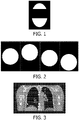
- Figure 1 show geometric distortion of an object of interest in a static CT image.
- 4D CT is an approach which mitigates this shortcoming.
- the patient is over sampled along his/her long axis at every subject support position of interest.
- Each CT slice is then correlated with a breathing phase of the respiratory cycle.
- the CT slices with similar breathing phase but acquired at different couch positions are binned together, sorted based on the couch position, and concatenated into a 3D image.
- 4D CT volume is a series of static CT images acquired at different breathing phases.
- a surrogate respiratory signal is used.
- One surrogate is determined via spirometry.
- spirometry the flow of air in and out of the lung is measured by breathing through a device that has a turbine-shaped fan enclosed in a tube. The rate of rotation of the fan determines the air flow rate and is measured as a respiratory signal.
- Another surrogate is to track reflective markers placed on the patient's chest or abdomen. The reflective markers move as the patient breath and their motion can be used as a respiratory signal.
- Another surrogate is an air-bellow belt that captures the change in abdomen size during breathing.
- FIG. 2 shows an example of motion artifact over four different phases of a 4D CT where the target is depicted at different locations in each image.
- Figure 3 shows a 4D CT image of the lungs, chest, and shoulder of a patient with example motion artifact 302.
- US 2014/343401 A1 discloses imaging a patient via CT and monitoring a marker (i.e., a tissue of interest) position via ultrasound imaging, wherein the marker positions are obtained during a data collection procedure.
- a marker i.e., a tissue of interest
- a method for determining a surrogate respiratory signal for four-dimensional computed tomography using ultrasound data includes, acquiring computed tomography data with a computed tomography imaging system, acquiring ultrasound data with a single-transducer ultrasound probe of an ultrasound imaging system concurrently with acquiring the computed tomography data during one or more respiratory cycles, wherein the ultrasound probe is aligned to acquire one-dimensional radio frequency data in M-mode of a diaphragm of a subject, synchronizing the acquired computed tomography data and the acquired ultrasound data, and detecting motion of a high intensity sub-portion in the radio frequency data to determine a surrogate respiratory signal from the acquired ultrasound data as an indicator of diaphragm movement.
- the invention may take form in various components and arrangements of components, and in various steps and arrangements of steps.
- the drawings are only for purposes of illustrating the preferred embodiments and are not to be construed as limiting the invention.
- FIGURE 4 schematically illustrates a system 400 including a CT imaging system 402 and an ultrasound (US) imaging system 404.
- the CT imaging system 402 includes a generally stationary gantry 406 and a rotating gantry 408, which is rotatably supported by the stationary gantry 406 and rotates around an examination region 410 about a z-axis.
- a subject support 407 such as a couch, supports an object or subject in the examination region 410.
- a radiation source 412 such as an x-ray tube, is rotatably supported by the rotating gantry 408, rotates with the rotating gantry 408, and emits radiation that traverses the examination region 410.
- a radiation sensitive detector array 414 subtends an angular arc opposite the radiation source 412 across the examination region 410. The radiation sensitive detector array 414 detects radiation traversing the examination region 410 and generates projection data, or a signal indicative thereof for each detected radiation.
- a reconstructor 416 reconstructs the signal and generates volumetric image data indicative of a scanned portion of a subject or object located in the examination region 410.
- a CT console 418 includes a human readable output device such as a monitor and an input device such as a keyboard, mouse, etc. Software resident on the CT console 418 allows the operator to interact with and/or operate the CT imaging system 402 via a graphical user interface (GUI) or otherwise.
- GUI graphical user interface
- the US imaging system 404 includes a probe 422 housing a transducer array 424.
- the transducer array 424 includes an array of transducer elements, each configured to transmit US signals through an acoustic window 426 and receive echo signals, which are created in response to the US signals interacting with structure in a field of view.
- the transducer array 424 is configured to acquire data which can be processed to generate a ID, 2D and/or 3D data. This includes single element imaging in M-mode, 2D imaging in B-mode, or 3D matrix imaging in B-mode.
- the probe 422 is supported by a device 429, which supports and maintains the probe 422 at a static known position during breathing and scanning.
- the probe 422 is attached to an encoded arm to measure its movement during breathing using the arm encoders.
- the probe 422 is supported and guided by a robotic arm.
- a tracking system employing optical, electromagnetic (EM), etc. tracking, optical shape sensing, etc. is utilized to track the probe 422.
- EM tracking is described in PCT/IB2013/054405, filed December 28, 2013 , published as WO2013179224A1 .
- the probe 422 interfaces through a cable 428 with a US console 430.
- the probe 422 may include a wireless interface.
- the US console 430 similar to the CT console 418, includes a human readable output device such as a monitor and an input device such as a keyboard, mouse, etc.
- software resident on the US console 430 allows the operator to interact with and/or operate the US imaging system 404 via a graphical user interface (GUI) or otherwise.
- GUI graphical user interface
- a data synchronization and 4D CT volume processor 432 processes CT data acquired by the CT imaging system 402 and US data acquired by the US imaging system 404. Where a tracking system is used to track the location of the transducer array 424, tracking information is also provided to the data synchronization and 4D CT volume processor 432. From this data, the data synchronization and 4D CT volume processor 432 associates each CT slice with US data (ID, 2D or 3D), a CT couch position, and a transducer array position/orientation (if available). This can be based on time stamps in the data, synchronizes clocks, a single clock, and/or otherwise.
- the data synchronization and 4D CT volume processor 432 processes the US data and generates a surrogate respiratory signal therefrom, which represents the phases of the respiratory cycles.
- the data synchronization and 4D CT volume processor 432 uses this surrogate respiratory signal to sort and combine the CT slices to generate the 4D CT volume. Since the surrogate respiratory signal reflects the actual movement of the diaphragm, the surrogate respiratory signal correlates well with the actual respiratory cycle, mitigating motion signal associated with using spirometry, markers, a belt, and other approaches which yield signals that do no correlates well with the actual respiratory cycle, introducing motion artifact.
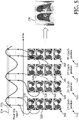
- FIG. 5 An example of the sorting and combining to generate 4D CT data is shown in Figure 5 .
- multiple sets CT slices 502, 504, 506, 508, ... are acquired at couch positions 510, 512, 514, 516, ....
- Each image corresponds to a respiratory phase/amplitude.
- the slices that have similar (same or within ⁇ 10%) breathing signal phase/amplitude are binned (e.g., slices 520, 522 and 524 having amplitude 526 are binned, slices 528, 530 and 532 having amplitude 534 are binned, etc.) together and sorted based on their couch position.
- the data synchronization and 4D CT volume processor 432 concatenates the images into a 3D volume 536 corresponding to a signal phase and displays the result.
- the data synchronization and 4D CT volume processor 432 is part of a computing system (with a processor, memory, etc.) separate from the CT imaging system 402 and the US imaging system 404.
- the data synchronization and 4D CT volume processor 432 is part of the CT imaging system console 418 and/or the US imaging system console 430.
- the data synchronization and 4D CT volume processor 432 is distributed across the CT imaging system 402 and/or the US imaging system 404 and one or more other computing systems.
- the CT volumetric data, the US data (ID, 2D and/or 3D), the tracking data (if acquired), the surrogate respiratory signal, the 3D volume 536, the 4D CT data, and/or other data can be stored in a data repository as electronically formatted data.
- a suitable data repository include a picture archiving and communication system (PACS), radiology information system (RIS), a hospital information system (HIS), an electronic medical record (EMR), a database, a server, etc.
- PES picture archiving and communication system
- RIS radiology information system
- HIS hospital information system
- EMR electronic medical record
- This data can also be stored with the CT imaging system 402 and/or the US imaging system 404.
- the data synchronization and 4D CT volume processor 432 processes the US data to generate a surrogate repository signal therefrom.
- the following describes non-limiting examples using ID, 2D and 3D US data to generate a surrogate repository signal.
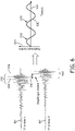
- the high intensity sub-portion 602 will move in the RF data 604 during the respiratory cycle.
- the difference between the locations 606 and 608 represents a shift 610 and corresponds to diaphragm motion, or the respiratory cycle.
- Figure 6 also shows a plot 612 of motion 614 (i.e., the shift 610) relative to the location 606 over time 616 for multiple respiratory cycles 618, 620 ... relative to a base line respiratory phase.
- the movement of the high intensity sub-portion 602 in the RF data 604 (e.g., the shift 610) is used as indicator of diaphragm movement and used as the surrogate for the respiratory cycle.
- Known and/or other motion detection algorithms can be used for motion detection of 602 in the RF data 604 such as cross-correlation or 1D Demons.
- the single element transducer can be fixed in space relative to the patient's body (as shown in Figure 4 ), as discussed herein.
- each CT slice is associated with one B-mode image.
- the surrogate signal is then generated based on one or more approaches.
- the diaphragm surface is segmented in the B-mode images.
- a surface 702 represents the segmented diaphragm.
- Diaphragm motion is then measured and compared via a baseline, either through an absolute distance measurement between diaphragm position in time t and the baseline diaphragm position at time 0, or by a summation of incremental diaphragm motions between time t and t-1.
- a cross correlation of B-mode image at time t and the baseline B-mode image (at time 0 ) is computed, and the cross correlation value are utilized as the surrogate signal.
- the probe 422 is either preferably fixed relative to the patient's body or tracked, as described herein.
- each CT slice is associated with a B-mode volume.
- the surrogate signal is generated based on one or more approaches.
- the diaphragm surface is segmented in the B-mode volume.
- the diaphragm motion is then measured and compared to a baseline volume, either through absolute distance measurement between diaphragm position in time t and the baseline diaphragm position at time 0, or by summation of incremental diaphragm motions between time t and t-1.
- a cross correlation of B-mode volume at time t and the baseline B-mode volume (at time 0) is computed, and the cross correlation value are utilized as the surrogate signal.
- FIGURE 8 illustrates an example method of generating and using a respiratory signal using a single transducer array 424 element in M-mode.
- a patient is positioned on the subject support 420 in the examination region 410 for a scan.
- the ultrasound probe 422 of the ultrasound imaging system 404 is suitably positioned on the patient to acquire an image of the diaphragm (e.g., intercostal or subcostal are two possibilities).
- the location of the ultrasound probe 422 with respect to the subject is tracked or fixed, as discussed herein and/or otherwise.
- the CT imaging system 102 and the US imaging system 104 are interfaced with the data synchronization and 4D CT volume processor 432.
- a CT scan and a US scan are concurrently performed while the patient normally breathes.
- a surrogate respiratory signal is generated from the acquired US data.
- the surrogate respiratory signal can be generated from ID, 2D and/or 3D US data.
- the data synchronization and 4D CT volume processor 432 employs the surrogate respiratory signal to sort and combine the CT slices to generate 4D CT volumetric data.
- the above may be implemented by way of computer readable instructions, encoded or embedded on non-transitory computer readable storage medium (physical memory, and excluding signals, carrier waves and other transitory medium), which, when executed by a computer processor(s) (e.g., a microprocessor, a controller, etc.), cause the computer processor(s) to carry out the described acts. Additionally or alternatively, at least one of the computer readable instructions is carried by a signal, carrier wave or other transitory medium.
- a computer processor(s) e.g., a microprocessor, a controller, etc.
Description
- The following generally relates to computed tomography and more particularly to respiratory motion compensation for four-dimensional computed tomography (4D CT) imaging using ultrasound. The following is also amenable to other imaging modalities.
- Motion due to the respiratory cycle (i.e., inhalation and exhalation of the lungs) can cause severe distortion in the geometry of target tissue of interest during a free-breathing static computed tomography (CT) scan. Free-breathing generally means the patient breathes during scanning. That is, the patient is not required to hold their breath. Static refers to the patient support being held at a same static position for the scan. The motion induced distortions can randomly shorten or lengthen the target tissue of interest. The distortions can also dislocate the center of the target tissue of interest.
Figure 1 show geometric distortion of an object of interest in a static CT image. - Because of these distortions, a free-breathing static CT scan is not well suited for dose planning for radiation therapy, especially for lung cancer tumors. 4D CT is an approach which mitigates this shortcoming. In 4D CT, the patient is over sampled along his/her long axis at every subject support position of interest. Each CT slice is then correlated with a breathing phase of the respiratory cycle. The CT slices with similar breathing phase but acquired at different couch positions are binned together, sorted based on the couch position, and concatenated into a 3D image. As such, 4D CT volume is a series of static CT images acquired at different breathing phases.
- In order to measure the breathing phase, a surrogate respiratory signal is used. One surrogate is determined via spirometry. In spirometry, the flow of air in and out of the lung is measured by breathing through a device that has a turbine-shaped fan enclosed in a tube. The rate of rotation of the fan determines the air flow rate and is measured as a respiratory signal. Another surrogate is to track reflective markers placed on the patient's chest or abdomen. The reflective markers move as the patient breath and their motion can be used as a respiratory signal. Another surrogate is an air-bellow belt that captures the change in abdomen size during breathing.
- Unfortunately, the above-noted approaches do not correlate well with the actual breathing phases of the respiratory cycle of a patient. As a consequence, 4D CT volumes often contain motion artifacts.
Figure 2 shows an example of motion artifact over four different phases of a 4D CT where the target is depicted at different locations in each image.Figure 3 shows a 4D CT image of the lungs, chest, and shoulder of a patient withexample motion artifact 302. In view of at least the above, there is an unresolved need for another approach for determining a motion signal that correlates well with the actual breathing phases of the respiratory cycle of a patient. -
US 2014/343401 A1 discloses imaging a patient via CT and monitoring a marker (i.e., a tissue of interest) position via ultrasound imaging, wherein the marker positions are obtained during a data collection procedure. - The invention is defined by the independent claims 1, 4 and 7. Aspects of the present application address the above-referenced matters and others.
- According to one aspect, a method for determining a surrogate respiratory signal for four-dimensional computed tomography using ultrasound data includes, acquiring computed tomography data with a computed tomography imaging system, acquiring ultrasound data with a single-transducer ultrasound probe of an ultrasound imaging system concurrently with acquiring the computed tomography data during one or more respiratory cycles, wherein the ultrasound probe is aligned to acquire one-dimensional radio frequency data in M-mode of a diaphragm of a subject, synchronizing the acquired computed tomography data and the acquired ultrasound data, and detecting motion of a high intensity sub-portion in the radio frequency data to determine a surrogate respiratory signal from the acquired ultrasound data as an indicator of diaphragm movement.
- In other aspects, a corresponding system and computer readable storage medium are provided as specified in the claims.
- Still further aspects of the present invention will be appreciated to those of ordinary skill in the art upon reading and understand the following detailed description.
- The invention may take form in various components and arrangements of components, and in various steps and arrangements of steps. The drawings are only for purposes of illustrating the preferred embodiments and are not to be construed as limiting the invention.
-
Figure 1 show geometric distortion of an object of interest in four static CT images. -
Figure 2 shows an example of motion artifact over four different phases of a 4D CT with the target at different locations. -
Figure 3 shows a 4D CT image of the lungs, chest, and shoulder of a patient with example motion artifact. -
Figure 4 schematically illustrates a system including a CT imaging system, an US imaging system, and a data synchronization and 4D CT volume processor. -
Figure 5 illustrates an example of sorting and combining data to generate 4D CT data. -
Figure 6 illustrates a high intensity sub-portion of 1D RF data as a function of respiratory phase. -
Figure 7 illustrates a segmented diaphragm surface in 2D ultrasound image data. -
Figure 8 illustrates an example method respiratory motion compensation for 4D CT using ultrasound. -
FIGURE 4 schematically illustrates asystem 400 including aCT imaging system 402 and an ultrasound (US)imaging system 404. TheCT imaging system 402 includes a generallystationary gantry 406 and a rotatinggantry 408, which is rotatably supported by thestationary gantry 406 and rotates around anexamination region 410 about a z-axis. Asubject support 407, such as a couch, supports an object or subject in theexamination region 410. - A
radiation source 412, such as an x-ray tube, is rotatably supported by the rotatinggantry 408, rotates with the rotatinggantry 408, and emits radiation that traverses theexamination region 410. A radiationsensitive detector array 414 subtends an angular arc opposite theradiation source 412 across theexamination region 410. The radiationsensitive detector array 414 detects radiation traversing theexamination region 410 and generates projection data, or a signal indicative thereof for each detected radiation. - A
reconstructor 416 reconstructs the signal and generates volumetric image data indicative of a scanned portion of a subject or object located in theexamination region 410. ACT console 418 includes a human readable output device such as a monitor and an input device such as a keyboard, mouse, etc. Software resident on theCT console 418 allows the operator to interact with and/or operate theCT imaging system 402 via a graphical user interface (GUI) or otherwise. - The US
imaging system 404 includes aprobe 422 housing atransducer array 424. Thetransducer array 424 includes an array of transducer elements, each configured to transmit US signals through anacoustic window 426 and receive echo signals, which are created in response to the US signals interacting with structure in a field of view. Thetransducer array 424 is configured to acquire data which can be processed to generate a ID, 2D and/or 3D data. This includes single element imaging in M-mode, 2D imaging in B-mode, or 3D matrix imaging in B-mode. - In the illustrated example, the
probe 422 is supported by a device 429, which supports and maintains theprobe 422 at a static known position during breathing and scanning. Alternatively, theprobe 422 is attached to an encoded arm to measure its movement during breathing using the arm encoders. Alternatively, theprobe 422 is supported and guided by a robotic arm. Alternatively, a tracking system employing optical, electromagnetic (EM), etc. tracking, optical shape sensing, etc. is utilized to track theprobe 422. An example of EM tracking is described inPCT/IB2013/054405, filed December 28, 2013 WO2013179224A1 . - In the illustrated example, the
probe 422 interfaces through acable 428 with aUS console 430. Alternatively, theprobe 422 may include a wireless interface. TheUS console 430, similar to theCT console 418, includes a human readable output device such as a monitor and an input device such as a keyboard, mouse, etc. Furthermore, like theCT console 418, software resident on theUS console 430 allows the operator to interact with and/or operate theUS imaging system 404 via a graphical user interface (GUI) or otherwise. - A data synchronization and 4D
CT volume processor 432 processes CT data acquired by theCT imaging system 402 and US data acquired by theUS imaging system 404. Where a tracking system is used to track the location of thetransducer array 424, tracking information is also provided to the data synchronization and 4DCT volume processor 432. From this data, the data synchronization and 4DCT volume processor 432 associates each CT slice with US data (ID, 2D or 3D), a CT couch position, and a transducer array position/orientation (if available). This can be based on time stamps in the data, synchronizes clocks, a single clock, and/or otherwise. - As described in greater detail below, the data synchronization and 4D
CT volume processor 432 processes the US data and generates a surrogate respiratory signal therefrom, which represents the phases of the respiratory cycles. The data synchronization and 4DCT volume processor 432 uses this surrogate respiratory signal to sort and combine the CT slices to generate the 4D CT volume. Since the surrogate respiratory signal reflects the actual movement of the diaphragm, the surrogate respiratory signal correlates well with the actual respiratory cycle, mitigating motion signal associated with using spirometry, markers, a belt, and other approaches which yield signals that do no correlates well with the actual respiratory cycle, introducing motion artifact. - An example of the sorting and combining to generate 4D CT data is shown in
Figure 5 . InFigure 5 , multiple sets CT slices 502, 504, 506, 508, ... are acquired atcouch positions amplitude 526 are binned, slices 528, 530 and 532 havingamplitude 534 are binned, etc.) together and sorted based on their couch position. The data synchronization and 4DCT volume processor 432 concatenates the images into a3D volume 536 corresponding to a signal phase and displays the result. - In the illustrated embodiment, the data synchronization and 4D
CT volume processor 432 is part of a computing system (with a processor, memory, etc.) separate from theCT imaging system 402 and theUS imaging system 404. In another embodiment, the data synchronization and 4DCT volume processor 432 is part of the CTimaging system console 418 and/or the USimaging system console 430. In yet another embodiment, the data synchronization and 4DCT volume processor 432 is distributed across theCT imaging system 402 and/or theUS imaging system 404 and one or more other computing systems. - The CT volumetric data, the US data (ID, 2D and/or 3D), the tracking data (if acquired), the surrogate respiratory signal, the
3D volume 536, the 4D CT data, and/or other data can be stored in a data repository as electronically formatted data. Examples of a suitable data repository include a picture archiving and communication system (PACS), radiology information system (RIS), a hospital information system (HIS), an electronic medical record (EMR), a database, a server, etc. This data can also be stored with theCT imaging system 402 and/or theUS imaging system 404. - As briefly described above, the data synchronization and 4D
CT volume processor 432 processes the US data to generate a surrogate repository signal therefrom. The following describes non-limiting examples using ID, 2D and 3D US data to generate a surrogate repository signal. - Where a single-transducer element is used in M-mode to acquire data, the acquired US data will include high intensity sub-portion in the RF data corresponding to the diaphragm interface, which is hyper-echoic. As example of this is shown in
Figure 6 , where ahigh intensity sub-portion 602 ofRF data 604 is centered about alocation 606 at t=0. - The
high intensity sub-portion 602 will move in theRF data 604 during the respiratory cycle. An example of this is also shown inFigure 6 , where thesub-portion 602 is shifted and is now centered about alocation 608 at t=x. The difference between thelocations shift 610 and corresponds to diaphragm motion, or the respiratory cycle.Figure 6 also shows a plot 612 of motion 614 (i.e., the shift 610) relative to thelocation 606 overtime 616 for multiplerespiratory cycles - In this example, the movement of the
high intensity sub-portion 602 in the RF data 604 (e.g., the shift 610) is used as indicator of diaphragm movement and used as the surrogate for the respiratory cycle. Known and/or other motion detection algorithms can be used for motion detection of 602 in theRF data 604 such as cross-correlation or 1D Demons. In this example, the single element transducer can be fixed in space relative to the patient's body (as shown inFigure 4 ), as discussed herein. - Where 2D US images is acquired in B-mode during CT scanning, each CT slice is associated with one B-mode image. The surrogate signal is then generated based on one or more approaches.
- With one approach, the diaphragm surface is segmented in the B-mode images. An example of this is shown in
Figure 7 . InFigure 7 , asurface 702 represents the segmented diaphragm. Diaphragm motion is then measured and compared via a baseline, either through an absolute distance measurement between diaphragm position in time t and the baseline diaphragm position attime 0, or by a summation of incremental diaphragm motions between time t and t-1. - In another approach, a cross correlation of B-mode image at time t and the baseline B-mode image (at time 0) is computed, and the cross correlation value are utilized as the surrogate signal. With this approach, as the diaphragm moves it results in a decorrelation between the image at time t and the baseline image. In both cases the
probe 422 is either preferably fixed relative to the patient's body or tracked, as described herein. - Where 3D US volumetric image data is acquired in B-mode during CT scanning each CT slice is associated with a B-mode volume. The surrogate signal is generated based on one or more approaches.
- With one approach, the diaphragm surface is segmented in the B-mode volume. The diaphragm motion is then measured and compared to a baseline volume, either through absolute distance measurement between diaphragm position in time t and the baseline diaphragm position at
time 0, or by summation of incremental diaphragm motions between time t and t-1. - In another approach, a cross correlation of B-mode volume at time t and the baseline B-mode volume (at time 0) is computed, and the cross correlation value are utilized as the surrogate signal. With this approach, as the diaphragm moves it results in a decorrelation between the image at time t and the baseline image. In both cases the
probe 422 is either fixed or tracked, as described herein. -
FIGURE 8 illustrates an example method of generating and using a respiratory signal using asingle transducer array 424 element in M-mode. - It is to be appreciated that the ordering of the above acts is not limiting. As such, other orderings are contemplated herein. In addition, one or more acts may be omitted and/or one or more additional acts may be included.
- At 802, a patient is positioned on the subject support 420 in the
examination region 410 for a scan. - At 804, the
ultrasound probe 422 of theultrasound imaging system 404 is suitably positioned on the patient to acquire an image of the diaphragm (e.g., intercostal or subcostal are two possibilities). - At 806, the location of the
ultrasound probe 422 with respect to the subject is tracked or fixed, as discussed herein and/or otherwise. - At 808, the CT imaging system 102 and the US imaging system 104 are interfaced with the data synchronization and 4D
CT volume processor 432. - At 810, a CT scan and a US scan are concurrently performed while the patient normally breathes.
- At 812, a surrogate respiratory signal is generated from the acquired US data. As described herein, the surrogate respiratory signal can be generated from ID, 2D and/or 3D US data.
- At 814, the data synchronization and 4D
CT volume processor 432 employs the surrogate respiratory signal to sort and combine the CT slices to generate 4D CT volumetric data. - The above may be implemented by way of computer readable instructions, encoded or embedded on non-transitory computer readable storage medium (physical memory, and excluding signals, carrier waves and other transitory medium), which, when executed by a computer processor(s) (e.g., a microprocessor, a controller, etc.), cause the computer processor(s) to carry out the described acts. Additionally or alternatively, at least one of the computer readable instructions is carried by a signal, carrier wave or other transitory medium.
- The invention has been described herein with reference to the various embodiments.
Claims (8)
- A method for determining a surrogate respiratory signal for four-dimensional computed tomography using ultrasound data, comprising:
acquiring computed tomography data with a computed tomography imaging system (402);
characterized in that the method further comprises:acquiring ultrasound data with a single-transducer ultrasound probe of an ultrasound imaging system (404) concurrently with acquiring the computed tomography data during one or more respiratory cycles, wherein the ultrasound probe is aligned to acquire one-dimensional radio frequency data (604) in M-mode of a diaphragm of a subject;synchronizing the acquired computed tomography data and the acquired ultrasound data; anddetecting motion of a high intensity sub-portion (602) in the radio frequency data (604) to determine a surrogate respiratory signal from the acquired ultrasound data as an indicator of diaphragm movement. - The method of claim 1, further comprising:sorting the computed tomography data using the surrogate respiratory signal;combining the sorted computed tomography data to generate the four-dimensional computed tomography.
- The method of claim 2, wherein the sorting includes binning image slices of the computed tomography data that have a similar amplitude based on the surrogate respiratory signal; sorting the binned images slices based on subject support position; and combining includes concatenating the sorted images into the four-dimensional computed tomography.
- A system (400), comprising:a computed tomography imaging system (402);an ultrasound imaging system (404) comprising a single-transducer ultrasound probe configured to acquire; anda data synchronization and four-dimensional computed tomography volume processor (421);characterized in that the computed tomography imaging system and the ultrasound imaging system are configured to concurrently acquire computed tomography imaging data and one-dimensional ultrasound imaging radio frequency data (604) in M-mode;wherein the data synchronization and four-dimensional computed tomography volume processor is configured to transform the ultrasound imaging data and determine a surrogate respiratory cycle signal representing an actual respiratory cycle of a scanned patient; andwherein the data synchronization and four-dimensional computed tomography volume processor is configured to transform the computed tomography imaging data using the surrogate respiratory cycle signal to construct four-dimensional computed tomography data.
- The system of claim 4, further comprising:
a support configured to maintain an ultrasound probe of the ultrasound imaging system at a fixed position while acquiring the ultrasound data. - The system of any of claims 4 to 5, wherein the data synchronization and four dimensional computed tomography volume processor is configured to synchronize the acquired computed tomography data and the acquired ultrasound data, sort the computed tomography data using the surrogate respiratory signal; and combine the sorted computed tomography data to generate the four-dimensional computed tomography.
- A computer readable storage medium encoded with computer readable instructions, which, when executed by a processor of a computing system, causes the processor to:concurrently acquire during one of more respiratory cycles computed tomography data from a computer tomography imaging system (402) and ultrasound data from a single-transducer ultrasound probe of an ultrasound imaging system (404), wherein the ultrasound probe is aligned to acquire one dimensional radio frequency data (604) in M-mode of a diaphragm of a subject;synchronize the acquired computed tomography data and the acquired ultrasound data;detecting motion of a high intensity sub-portion (602) in the radio frequency data (604) to determine a surrogate respiratory signal from the acquired ultrasound data as an indicator of diaphragm movement.
- A computer readable storage medium according to claim 7, encoded with further computer readable instructions, which, when executed by a processor of a computing system, causes the processor to:bin image slices of the computed tomography data that have a similar amplitude based on the surrogate respiratory signal;sort the binned image slices based a subject support position; andcombine the sorted image slices by concatenating the sorted images into a three dimensional volume corresponding to respiratory phase.
Applications Claiming Priority (2)
| Application Number | Priority Date | Filing Date | Title |
|---|---|---|---|
| US201562219184P | 2015-09-16 | 2015-09-16 | |
| PCT/IB2016/055296 WO2017046674A1 (en) | 2015-09-16 | 2016-09-05 | Respiratory motion compensation for four-dimensional computed tomography imaging using ultrasound |
Publications (2)
| Publication Number | Publication Date |
|---|---|
| EP3349658A1 EP3349658A1 (en) | 2018-07-25 |
| EP3349658B1 true EP3349658B1 (en) | 2022-08-03 |
Family
ID=56894028
Family Applications (1)
| Application Number | Title | Priority Date | Filing Date |
|---|---|---|---|
| EP16763329.6A Active EP3349658B1 (en) | 2015-09-16 | 2016-09-05 | Respiratory motion compensation for four-dimensional computed tomography imaging using ultrasound |
Country Status (5)
| Country | Link |
|---|---|
| US (1) | US10546397B2 (en) |
| EP (1) | EP3349658B1 (en) |
| JP (1) | JP2018527091A (en) |
| CN (1) | CN108024780B (en) |
| WO (1) | WO2017046674A1 (en) |
Families Citing this family (7)
| Publication number | Priority date | Publication date | Assignee | Title |
|---|---|---|---|---|
| US20170169609A1 (en) * | 2014-02-19 | 2017-06-15 | Koninklijke Philips N.V. | Motion adaptive visualization in medical 4d imaging |
| EP3508132A1 (en) | 2018-01-04 | 2019-07-10 | Koninklijke Philips N.V. | Ultrasound system and method for correcting motion-induced misalignment in image fusion |
| WO2019195044A1 (en) * | 2018-04-05 | 2019-10-10 | Siemens Medical Solutions Usa, Inc. | Motion signal derived from imaging data |
| EP3628225B1 (en) * | 2018-09-26 | 2021-03-31 | Siemens Healthcare GmbH | Method for recording image data and medical imaging system |
| CN113301845A (en) * | 2018-12-11 | 2021-08-24 | 雷斯皮诺尔公共有限责任公司 | System and method for motion compensation in ultrasound respiration monitoring |
| CN111632283A (en) * | 2020-04-27 | 2020-09-08 | 深圳市普罗医学股份有限公司 | Ultrasonic treatment equipment for chest and lung treatment |
| WO2023030497A1 (en) * | 2021-09-02 | 2023-03-09 | Shanghai United Imaging Healthcare Co., Ltd. | Systems and methods for medical imaging |
Family Cites Families (15)
| Publication number | Priority date | Publication date | Assignee | Title |
|---|---|---|---|---|
| US8814793B2 (en) * | 2002-12-03 | 2014-08-26 | Neorad As | Respiration monitor |
| EP1631194A1 (en) * | 2003-05-21 | 2006-03-08 | Philips Intellectual Property & Standards GmbH | Apparatus and method for recording the movement of organs of the body |
| US7542544B2 (en) | 2004-01-06 | 2009-06-02 | The Regents Of The University Of Michigan | Ultrasound gating of cardiac CT scans |
| US7395563B2 (en) * | 2004-04-02 | 2008-07-08 | Civco Medical Instruments Co., Inc. | Support system for use when performing medical imaging of a patient |
| RU2431443C2 (en) | 2005-08-04 | 2011-10-20 | Конинклейке Филипс Электроникс Н.В. | Motion compensation in functional image formation |
| CA2651994C (en) | 2006-05-17 | 2016-04-19 | Koninklijke Philips Electronics N.V. | Retrospective sorting of 4d ct into breathing phases based on geometric analysis of imaging fiducials |
| CN101969857B (en) | 2008-01-23 | 2014-08-20 | M·阿韦基乌 | Therapy assessment with ultrasonic contrast agents |
| US8526702B2 (en) * | 2011-01-06 | 2013-09-03 | The Board Of Trustees Of The Leland Standford Junior University | 4D anatomically based image selection procedure for medical imaging |
| WO2012142031A1 (en) | 2011-04-12 | 2012-10-18 | Brigham And Women's Hospital, Inc. | System and method for motion tracking using unique ultrasound echo signatures |
| CA2781536C (en) | 2011-06-29 | 2017-11-07 | University Of Maryland, Baltimore | Techniques for compensating movement of a treatment target in a patient |
| CN103222874B (en) * | 2012-01-31 | 2016-12-07 | Ge医疗系统环球技术有限公司 | The method of selection CT sectioning image and the method for structure CT 3-D view |
| DE102012209984B4 (en) | 2012-06-14 | 2018-12-27 | Siemens Healthcare Gmbh | Investigation of the position of the diaphragm of a living being |
| US20140270448A1 (en) | 2013-03-15 | 2014-09-18 | University Of Macau | System and method for attenuation correction in emission computed tomography |
| US20160074674A1 (en) | 2013-04-11 | 2016-03-17 | British Columbia Cancer Agency Branch | Combined respiration and cardiac gating for radiotherapy using electrical impedance technology |
| US20140343401A1 (en) * | 2013-05-14 | 2014-11-20 | Michael Huber | Systems and methods for considering target motion in medical field |
-
2016
- 2016-09-05 JP JP2018512398A patent/JP2018527091A/en active Pending
- 2016-09-05 US US15/756,119 patent/US10546397B2/en active Active
- 2016-09-05 CN CN201680053911.8A patent/CN108024780B/en active Active
- 2016-09-05 WO PCT/IB2016/055296 patent/WO2017046674A1/en active Application Filing
- 2016-09-05 EP EP16763329.6A patent/EP3349658B1/en active Active
Also Published As
| Publication number | Publication date |
|---|---|
| WO2017046674A1 (en) | 2017-03-23 |
| JP2018527091A (en) | 2018-09-20 |
| US10546397B2 (en) | 2020-01-28 |
| EP3349658A1 (en) | 2018-07-25 |
| CN108024780A (en) | 2018-05-11 |
| US20180247435A1 (en) | 2018-08-30 |
| CN108024780B (en) | 2022-04-05 |
Similar Documents
| Publication | Publication Date | Title |
|---|---|---|
| EP3349658B1 (en) | Respiratory motion compensation for four-dimensional computed tomography imaging using ultrasound | |
| KR102522539B1 (en) | Medical image displaying apparatus and medical image processing method thereof | |
| JP5155304B2 (en) | Retrospective sorting of 4D CT into respiratory phase based on geometric analysis of imaging criteria | |
| KR101618213B1 (en) | Information providing method and apparatus for aligning x-ray tube and detector of mobile x-ray, and wireless detector | |
| EP2790587B1 (en) | Three dimensional mapping display system for diagnostic ultrasound machines | |
| US20050201509A1 (en) | Breathing synchronized computed tomography image acquisition | |
| KR102369652B1 (en) | Image processing apparatus, medical image apparatus and processing method for the medical image | |
| EP2293720B1 (en) | Motion compensation for medical imaging and associated systems and methods | |
| US20090088622A1 (en) | Systems and methods for associating physiological data with image data | |
| US9508154B2 (en) | Medical imaging apparatus and method of operating the same | |
| WO2014011681A2 (en) | Super-resolution tomosynthesis imaging systems and methods | |
| US7844317B2 (en) | Method and system for estimating three-dimensional respiratory motion | |
| US20070016005A1 (en) | Apparatus and method for recording the movement of organs of the body | |
| EP2575616B1 (en) | Amplitude/slope-based motion phase mapping | |
| US20020172328A1 (en) | 3-D Navigation for X-ray imaging system | |
| US8489176B1 (en) | Radioactive emission detector equipped with a position tracking system and utilization thereof with medical systems and in medical procedures | |
| JP2014518125A (en) | Follow-up image acquisition plan and / or post-processing | |
| EP3847478A1 (en) | Compact antenna arrangement of radar system for detecting internal organ motion | |
| CN101304688A (en) | Signal processing unit for producing images | |
| US11744558B2 (en) | Systems and methods for controlling imaging artifacts using an array of sensor data | |
| RU2154982C2 (en) | Device for diagnosing gastroenteric tract using radiotelemetry | |
| TW202110404A (en) | Ultrasonic image system enables the processing unit to obtain correspondingly two-dimensional ultrasonic image when the ultrasonic probe is at different inclination angles |
Legal Events
| Date | Code | Title | Description |
|---|---|---|---|
| STAA | Information on the status of an ep patent application or granted ep patent |
Free format text: STATUS: THE INTERNATIONAL PUBLICATION HAS BEEN MADE |
|
| PUAI | Public reference made under article 153(3) epc to a published international application that has entered the european phase |
Free format text: ORIGINAL CODE: 0009012 |
|
| STAA | Information on the status of an ep patent application or granted ep patent |
Free format text: STATUS: REQUEST FOR EXAMINATION WAS MADE |
|
| 17P | Request for examination filed |
Effective date: 20180416 |
|
| AK | Designated contracting states |
Kind code of ref document: A1 Designated state(s): AL AT BE BG CH CY CZ DE DK EE ES FI FR GB GR HR HU IE IS IT LI LT LU LV MC MK MT NL NO PL PT RO RS SE SI SK SM TR |
|
| AX | Request for extension of the european patent |
Extension state: BA ME |
|
| DAV | Request for validation of the european patent (deleted) | ||
| DAX | Request for extension of the european patent (deleted) | ||
| STAA | Information on the status of an ep patent application or granted ep patent |
Free format text: STATUS: EXAMINATION IS IN PROGRESS |
|
| 17Q | First examination report despatched |
Effective date: 20191105 |
|
| RAP1 | Party data changed (applicant data changed or rights of an application transferred) |
Owner name: KONINKLIJKE PHILIPS N.V. |
|
| STAA | Information on the status of an ep patent application or granted ep patent |
Free format text: STATUS: EXAMINATION IS IN PROGRESS |
|
| STAA | Information on the status of an ep patent application or granted ep patent |
Free format text: STATUS: EXAMINATION IS IN PROGRESS |
|
| GRAP | Despatch of communication of intention to grant a patent |
Free format text: ORIGINAL CODE: EPIDOSNIGR1 |
|
| STAA | Information on the status of an ep patent application or granted ep patent |
Free format text: STATUS: GRANT OF PATENT IS INTENDED |
|
| RIC1 | Information provided on ipc code assigned before grant |
Ipc: A61B 5/08 20060101ALN20220210BHEP Ipc: A61B 5/00 20060101ALI20220210BHEP Ipc: G06T 11/00 20060101ALI20220210BHEP Ipc: A61B 8/08 20060101ALI20220210BHEP Ipc: A61B 6/00 20060101ALI20220210BHEP Ipc: A61B 6/03 20060101AFI20220210BHEP |
|
| INTG | Intention to grant announced |
Effective date: 20220228 |
|
| GRAS | Grant fee paid |
Free format text: ORIGINAL CODE: EPIDOSNIGR3 |
|
| GRAA | (expected) grant |
Free format text: ORIGINAL CODE: 0009210 |
|
| STAA | Information on the status of an ep patent application or granted ep patent |
Free format text: STATUS: THE PATENT HAS BEEN GRANTED |
|
| AK | Designated contracting states |
Kind code of ref document: B1 Designated state(s): AL AT BE BG CH CY CZ DE DK EE ES FI FR GB GR HR HU IE IS IT LI LT LU LV MC MK MT NL NO PL PT RO RS SE SI SK SM TR |
|
| REG | Reference to a national code |
Ref country code: AT Ref legal event code: REF Ref document number: 1508112 Country of ref document: AT Kind code of ref document: T Effective date: 20220815 Ref country code: CH Ref legal event code: EP |
|
| REG | Reference to a national code |
Ref country code: DE Ref legal event code: R096 Ref document number: 602016073959 Country of ref document: DE |
|
| REG | Reference to a national code |
Ref country code: IE Ref legal event code: FG4D |
|
| REG | Reference to a national code |
Ref country code: DE Ref legal event code: R084 Ref document number: 602016073959 Country of ref document: DE |
|
| REG | Reference to a national code |
Ref country code: GB Ref legal event code: 746 Effective date: 20221013 |
|
| REG | Reference to a national code |
Ref country code: LT Ref legal event code: MG9D |
|
| REG | Reference to a national code |
Ref country code: NL Ref legal event code: MP Effective date: 20220803 |
|
| PG25 | Lapsed in a contracting state [announced via postgrant information from national office to epo] |
Ref country code: SE Free format text: LAPSE BECAUSE OF FAILURE TO SUBMIT A TRANSLATION OF THE DESCRIPTION OR TO PAY THE FEE WITHIN THE PRESCRIBED TIME-LIMIT Effective date: 20220803 Ref country code: RS Free format text: LAPSE BECAUSE OF FAILURE TO SUBMIT A TRANSLATION OF THE DESCRIPTION OR TO PAY THE FEE WITHIN THE PRESCRIBED TIME-LIMIT Effective date: 20220803 Ref country code: PT Free format text: LAPSE BECAUSE OF FAILURE TO SUBMIT A TRANSLATION OF THE DESCRIPTION OR TO PAY THE FEE WITHIN THE PRESCRIBED TIME-LIMIT Effective date: 20221205 Ref country code: NO Free format text: LAPSE BECAUSE OF FAILURE TO SUBMIT A TRANSLATION OF THE DESCRIPTION OR TO PAY THE FEE WITHIN THE PRESCRIBED TIME-LIMIT Effective date: 20221103 Ref country code: NL Free format text: LAPSE BECAUSE OF FAILURE TO SUBMIT A TRANSLATION OF THE DESCRIPTION OR TO PAY THE FEE WITHIN THE PRESCRIBED TIME-LIMIT Effective date: 20220803 Ref country code: LV Free format text: LAPSE BECAUSE OF FAILURE TO SUBMIT A TRANSLATION OF THE DESCRIPTION OR TO PAY THE FEE WITHIN THE PRESCRIBED TIME-LIMIT Effective date: 20220803 Ref country code: LT Free format text: LAPSE BECAUSE OF FAILURE TO SUBMIT A TRANSLATION OF THE DESCRIPTION OR TO PAY THE FEE WITHIN THE PRESCRIBED TIME-LIMIT Effective date: 20220803 Ref country code: FI Free format text: LAPSE BECAUSE OF FAILURE TO SUBMIT A TRANSLATION OF THE DESCRIPTION OR TO PAY THE FEE WITHIN THE PRESCRIBED TIME-LIMIT Effective date: 20220803 Ref country code: ES Free format text: LAPSE BECAUSE OF FAILURE TO SUBMIT A TRANSLATION OF THE DESCRIPTION OR TO PAY THE FEE WITHIN THE PRESCRIBED TIME-LIMIT Effective date: 20220803 |
|
| REG | Reference to a national code |
Ref country code: AT Ref legal event code: MK05 Ref document number: 1508112 Country of ref document: AT Kind code of ref document: T Effective date: 20220803 |
|
| PG25 | Lapsed in a contracting state [announced via postgrant information from national office to epo] |
Ref country code: PL Free format text: LAPSE BECAUSE OF FAILURE TO SUBMIT A TRANSLATION OF THE DESCRIPTION OR TO PAY THE FEE WITHIN THE PRESCRIBED TIME-LIMIT Effective date: 20220803 Ref country code: IS Free format text: LAPSE BECAUSE OF FAILURE TO SUBMIT A TRANSLATION OF THE DESCRIPTION OR TO PAY THE FEE WITHIN THE PRESCRIBED TIME-LIMIT Effective date: 20221203 Ref country code: HR Free format text: LAPSE BECAUSE OF FAILURE TO SUBMIT A TRANSLATION OF THE DESCRIPTION OR TO PAY THE FEE WITHIN THE PRESCRIBED TIME-LIMIT Effective date: 20220803 Ref country code: GR Free format text: LAPSE BECAUSE OF FAILURE TO SUBMIT A TRANSLATION OF THE DESCRIPTION OR TO PAY THE FEE WITHIN THE PRESCRIBED TIME-LIMIT Effective date: 20221104 |
|
| PG25 | Lapsed in a contracting state [announced via postgrant information from national office to epo] |
Ref country code: SM Free format text: LAPSE BECAUSE OF FAILURE TO SUBMIT A TRANSLATION OF THE DESCRIPTION OR TO PAY THE FEE WITHIN THE PRESCRIBED TIME-LIMIT Effective date: 20220803 Ref country code: RO Free format text: LAPSE BECAUSE OF FAILURE TO SUBMIT A TRANSLATION OF THE DESCRIPTION OR TO PAY THE FEE WITHIN THE PRESCRIBED TIME-LIMIT Effective date: 20220803 Ref country code: DK Free format text: LAPSE BECAUSE OF FAILURE TO SUBMIT A TRANSLATION OF THE DESCRIPTION OR TO PAY THE FEE WITHIN THE PRESCRIBED TIME-LIMIT Effective date: 20220803 Ref country code: CZ Free format text: LAPSE BECAUSE OF FAILURE TO SUBMIT A TRANSLATION OF THE DESCRIPTION OR TO PAY THE FEE WITHIN THE PRESCRIBED TIME-LIMIT Effective date: 20220803 Ref country code: AT Free format text: LAPSE BECAUSE OF FAILURE TO SUBMIT A TRANSLATION OF THE DESCRIPTION OR TO PAY THE FEE WITHIN THE PRESCRIBED TIME-LIMIT Effective date: 20220803 |
|
| REG | Reference to a national code |
Ref country code: CH Ref legal event code: PL |
|
| REG | Reference to a national code |
Ref country code: DE Ref legal event code: R097 Ref document number: 602016073959 Country of ref document: DE |
|
| REG | Reference to a national code |
Ref country code: BE Ref legal event code: MM Effective date: 20220930 |
|
| PG25 | Lapsed in a contracting state [announced via postgrant information from national office to epo] |
Ref country code: SK Free format text: LAPSE BECAUSE OF FAILURE TO SUBMIT A TRANSLATION OF THE DESCRIPTION OR TO PAY THE FEE WITHIN THE PRESCRIBED TIME-LIMIT Effective date: 20220803 Ref country code: MC Free format text: LAPSE BECAUSE OF FAILURE TO SUBMIT A TRANSLATION OF THE DESCRIPTION OR TO PAY THE FEE WITHIN THE PRESCRIBED TIME-LIMIT Effective date: 20220803 Ref country code: EE Free format text: LAPSE BECAUSE OF FAILURE TO SUBMIT A TRANSLATION OF THE DESCRIPTION OR TO PAY THE FEE WITHIN THE PRESCRIBED TIME-LIMIT Effective date: 20220803 |
|
| PLBE | No opposition filed within time limit |
Free format text: ORIGINAL CODE: 0009261 |
|
| STAA | Information on the status of an ep patent application or granted ep patent |
Free format text: STATUS: NO OPPOSITION FILED WITHIN TIME LIMIT |
|
| PG25 | Lapsed in a contracting state [announced via postgrant information from national office to epo] |
Ref country code: LU Free format text: LAPSE BECAUSE OF NON-PAYMENT OF DUE FEES Effective date: 20220905 Ref country code: AL Free format text: LAPSE BECAUSE OF FAILURE TO SUBMIT A TRANSLATION OF THE DESCRIPTION OR TO PAY THE FEE WITHIN THE PRESCRIBED TIME-LIMIT Effective date: 20220803 |
|
| 26N | No opposition filed |
Effective date: 20230504 |
|
| PG25 | Lapsed in a contracting state [announced via postgrant information from national office to epo] |
Ref country code: LI Free format text: LAPSE BECAUSE OF NON-PAYMENT OF DUE FEES Effective date: 20220930 Ref country code: IE Free format text: LAPSE BECAUSE OF NON-PAYMENT OF DUE FEES Effective date: 20220905 Ref country code: FR Free format text: LAPSE BECAUSE OF NON-PAYMENT OF DUE FEES Effective date: 20221003 Ref country code: CH Free format text: LAPSE BECAUSE OF NON-PAYMENT OF DUE FEES Effective date: 20220930 |
|
| PG25 | Lapsed in a contracting state [announced via postgrant information from national office to epo] |
Ref country code: SI Free format text: LAPSE BECAUSE OF FAILURE TO SUBMIT A TRANSLATION OF THE DESCRIPTION OR TO PAY THE FEE WITHIN THE PRESCRIBED TIME-LIMIT Effective date: 20220803 |
|
| PG25 | Lapsed in a contracting state [announced via postgrant information from national office to epo] |
Ref country code: BE Free format text: LAPSE BECAUSE OF NON-PAYMENT OF DUE FEES Effective date: 20220930 |
|
| PGFP | Annual fee paid to national office [announced via postgrant information from national office to epo] |
Ref country code: GB Payment date: 20230926 Year of fee payment: 8 |
|
| PGFP | Annual fee paid to national office [announced via postgrant information from national office to epo] |
Ref country code: DE Payment date: 20230928 Year of fee payment: 8 |
|
| PG25 | Lapsed in a contracting state [announced via postgrant information from national office to epo] |
Ref country code: HU Free format text: LAPSE BECAUSE OF FAILURE TO SUBMIT A TRANSLATION OF THE DESCRIPTION OR TO PAY THE FEE WITHIN THE PRESCRIBED TIME-LIMIT; INVALID AB INITIO Effective date: 20160905 |