EP3349220A1 - Grating and radiation imaging device - Google Patents
Grating and radiation imaging device Download PDFInfo
- Publication number
- EP3349220A1 EP3349220A1 EP16843540.2A EP16843540A EP3349220A1 EP 3349220 A1 EP3349220 A1 EP 3349220A1 EP 16843540 A EP16843540 A EP 16843540A EP 3349220 A1 EP3349220 A1 EP 3349220A1
- Authority
- EP
- European Patent Office
- Prior art keywords
- sheet
- grating
- sheets
- stacked
- present disclosure
- Prior art date
- Legal status (The legal status is an assumption and is not a legal conclusion. Google has not performed a legal analysis and makes no representation as to the accuracy of the status listed.)
- Granted
Links
Images

Classifications
-
- G—PHYSICS
- G21—NUCLEAR PHYSICS; NUCLEAR ENGINEERING
- G21K—HANDLING OF PARTICLES OR IONISING RADIATION NOT OTHERWISE PROVIDED FOR; IRRADIATION DEVICES; GAMMA RAY OR X-RAY MICROSCOPES
- G21K1/00—Arrangements for handling particles or ionising radiation, e.g. focusing or moderating
- G21K1/06—Arrangements for handling particles or ionising radiation, e.g. focusing or moderating using diffraction, refraction or reflection, e.g. monochromators
-
- G—PHYSICS
- G02—OPTICS
- G02B—OPTICAL ELEMENTS, SYSTEMS OR APPARATUS
- G02B5/00—Optical elements other than lenses
- G02B5/18—Diffraction gratings
- G02B5/1838—Diffraction gratings for use with ultraviolet radiation or X-rays
-
- G—PHYSICS
- G21—NUCLEAR PHYSICS; NUCLEAR ENGINEERING
- G21K—HANDLING OF PARTICLES OR IONISING RADIATION NOT OTHERWISE PROVIDED FOR; IRRADIATION DEVICES; GAMMA RAY OR X-RAY MICROSCOPES
- G21K1/00—Arrangements for handling particles or ionising radiation, e.g. focusing or moderating
- G21K1/02—Arrangements for handling particles or ionising radiation, e.g. focusing or moderating using diaphragms, collimators
- G21K1/025—Arrangements for handling particles or ionising radiation, e.g. focusing or moderating using diaphragms, collimators using multiple collimators, e.g. Bucky screens; other devices for eliminating undesired or dispersed radiation
-
- G—PHYSICS
- G21—NUCLEAR PHYSICS; NUCLEAR ENGINEERING
- G21K—HANDLING OF PARTICLES OR IONISING RADIATION NOT OTHERWISE PROVIDED FOR; IRRADIATION DEVICES; GAMMA RAY OR X-RAY MICROSCOPES
- G21K2201/00—Arrangements for handling radiation or particles
- G21K2201/06—Arrangements for handling radiation or particles using diffractive, refractive or reflecting elements
- G21K2201/067—Construction details
-
- G—PHYSICS
- G21—NUCLEAR PHYSICS; NUCLEAR ENGINEERING
- G21K—HANDLING OF PARTICLES OR IONISING RADIATION NOT OTHERWISE PROVIDED FOR; IRRADIATION DEVICES; GAMMA RAY OR X-RAY MICROSCOPES
- G21K2207/00—Particular details of imaging devices or methods using ionizing electromagnetic radiation such as X-rays or gamma rays
- G21K2207/005—Methods and devices obtaining contrast from non-absorbing interaction of the radiation with matter, e.g. phase contrast
Definitions
- the present disclosure relates to a grating and a radiation imaging device, and belongs to the technical field of radiation imaging.
- a grating is a component for measuring based on distance between lines on the grating.
- the grating may be classified into geometrical grating (amplitude grating) and diffraction grating (phase grating) according to different principles of forming moire fringes.
- the geometrical grating is adopted in micro-scale and submicron-scale grating measurement, in which a grating pitch of 100 to 20 ⁇ m is much greater than light wavelengths of light sources and diffraction phenomenon can be negligible. When two gratings move with respect to each other, low frequency beat phenomenon is generated and thus moire fringes are formed. This measurement principle is referred to as an image principle.
- the diffraction grating is adopted in nano-scale grating measurement, in which a grating pitch is 8 or 4 ⁇ m, a width of line is very close to wavelength of light, and diffraction and interference phenomena are generated and thus moire fringes are formed.
- This measurement principle is referred to as an interference principle.
- the grating includes a light transmission portion (hereinafter referred to as "slit width") and a light shielding portion (hereinafter referred to as "grid”), and thereby light incident on the grating is divided into several light beams.
- slit width a light transmission portion
- grid a light shielding portion
- the diffraction grating diffracts light from a source grating, and forms an interference pattern according to the Talbot effect.
- a light detector detects the light from the diffraction grating.
- an X-ray absorbing grating shall be arranged behind an X-ray source.
- a portion (grid) of the X-ray absorbing grating in which a heavy metal is filled absorbs X rays, and X rays transmit through the other portion (grating slit) of the grating, such that the absorbing grating and the common grating X-ray source conjointly form an X-ray source having one-dimensional spatial coherence.
- gratings in radiation imaging devices.
- Existing methods for manufacturing gratings mainly include mechanical ruling, laser holographic lithography and electron beam lithography.
- the mechanical ruling has very strict requirements and following disadvantages: long processing time, low precision, high production difficulty, and hard to rule sub-micron lines.
- the electron beam lithography is able to form nano-scale high resolution pattern, but has a very low efficiency and cannot form patterns with high aspect ratios.
- the laser holographic lithography is able to form gratings in deep sub-micron levels, but has a high control precision, high cost and low productivity.
- An objective of the present disclosure is to solve the following problem that existing X-ray grating formed with chemical corrosion has a low forming efficiency and high cost, and thus cannot be used along with high-energy X-rays.
- the present disclosure provides a grating and a radiation imaging device.
- the present disclosure provides a grating, including: a plurality of stacked grating elements, wherein the grating elements are stacked to form a grid; the grating element comprises a first sheet and a second sheet having two parallel planes; the second sheet is stacked at the first sheet in a length direction of the first sheet; and the first sheet is almost impervious to radiation.
- the second sheet has a length smaller than that of the first sheet, and there are at least two second sheets; and the second sheets are stacked at two ends on an identical surface of the first sheet in the length direction of the first sheet, such that a grating slit is formed between adjacent first sheets.
- the grating slit is filled with a material pervious to radiation.
- the first sheet has a thickness different from that of the second sheet.
- each of the first sheet and the second sheet has a thickness of 0.001 to 3 millimeters.
- the grating element further comprises a third sheet, wherein the third sheet has a length smaller than that of the first sheet, at least three second sheets are stacked at the two ends and a middle position of an identical surface of the first sheet in the length direction of the first sheet, and the third sheet is stacked on the first sheet between two of the second sheets.
- the third sheet has a thickness smaller than that of the second sheet.
- the second sheet has a length same with that of the first sheet; and the second sheet is pervious to radiation.
- the first sheet has a thickness different from that of the second sheet.
- each of the first sheet and the second sheet has a thickness of 0.001 to 3 millimeters.
- the first sheet is a high-density sheet.
- the first sheet is a tungsten alloy sheet.
- the grating elements are bonded with adhesives or compressed with tools to be assembled into the grating.
- the present disclosure provides a radiation imaging device, characterized by the above-mentioned grating.
- the grating and the radiation imaging device stack the sheets having different specifications together to form the grating with uniform grating slits, such that there is no limitation on the thickness of the grating and the grating can be used along with high-energy radiations.
- the present disclosure provides a grating, including a plurality of stacked grating elements 1, wherein the grating elements 1 are stacked to form a grid.
- the grating element 1 includes a first sheet 11, 21 and a second sheet 12, 22 having two parallel planes.
- the second sheet 12, 22 is stacked at the first sheet 11, 21 in a length direction of the first sheet 11, 21.
- the first sheet 11, 21 is almost impervious to radiation.
- the grating element 1 includes a first sheet 11 and second sheets 12.
- the second sheet 12 has a length smaller than that of the first sheet 11, and at least two second sheets 12 are stacked at two ends on an identical surface of the first sheet 11 in a length direction of the first sheet 11, such that a grating slit is formed between adjacent first sheets 11.
- the grating element 1 is formed of sheets having two different lengths, wherein the first sheet 11 and the second sheet 12 have different lengths.
- the two second sheets 12 are stacked at two ends on the identical surface of the first sheet 11.
- the first sheet 11 has a thickness same with or different from that of the second sheets 12.
- the thickness of the first sheet 11 determines a width of grating line
- the thickness of the second sheet 12 determines a width of grating slit.
- grating elements 1 composed of first sheets 11 and second sheets 12 having the same thickness according to the present disclosure, wherein the grating lines and the grating slits have same widths.
- Gratings with different duty ratios can be manufactured by adjusting the thicknesses of the first sheets 11 and the second sheets 12.
- the thicknesses of the first sheets and the second sheets can be preferably ranged from 0.001 to 3 millimeters.
- the first sheet 11 has a thickness smaller than that of the second sheets 12 in this example.
- the grating line has a width smaller than that of the grating slit.
- the grating slit is formed between adjacent first sheets 11. In order to prevent deformation of the first sheets when the grating is formed from multiple grating elements 1, the grating slits are filled with a thin material, which is pervious to radiation.
- the first sheet 11 has a thickness larger than that of the second sheet 12 in this example.
- the grating line has a width larger than that of the grating slit.
- this example is substantially same as example 1, but differs in that in this example, the grating element 1 is formed from sheets having three different lengths.
- the first sheet 11 and the second sheet 12 have different lengths.
- the grating element further includes a third sheet 13, which has a length smaller than that of the first sheet 11.
- At least three second sheets 12 are stacked at two ends and a middle position on an identical surface of the first sheet 11 in a length direction of the first sheet 11.
- the third sheet 13 is stacked at the first sheet 11 between two of the second sheets 12.
- the length of the third sheet 13 may be determined according to a length of a gap formed by the first sheet 11 and the second sheets 12.
- the length of the third sheet 13 may be the same with the length of the gap formed by the first sheet 11 and the second sheets 12. If the gap formed by the first sheet 11 and the second sheets 12 has a length same with that of the second sheet 12, the length of the third sheet 13 may be as also same with that of the second sheet 12. As shown in FIG. 9 , in order to form a grating structure having another duty ratio in a same grating, the thickness of the third sheet 13 should be adjusted accordingly. When the third sheet 13 is stacked at the first sheet 11 between two of the second sheets 12, the thickness of the third sheet 13 is smaller than that of the second sheet 12.
- gratings having different duty ratios can also be further formed by combining more different sheets.
- this example is substantially same as example 1, but differs in that in this example, the grating element 1 is formed of four kinds of different sheets, wherein a fourth sheet 14 is further provided.
- At least four second sheets 12 are stacked on an identical surface of the first sheet 11 in a length direction of the first sheet 11.
- the third sheet 13 is stacked at the first sheet 11 between two of the second sheets 12.
- the fourth sheet 14 is further stacked at the third sheet 13.
- the first sheet 11 and the second sheet 12 of the grating element 1 are sheets almost impervious to radiation, e.g., sheets made of a high-density material, preferably tungsten alloy sheets.
- the grating formed from the grating elements 1 has a thickness consistent with the widths of the sheets, and the grating according to the present disclosure can be used along with high-energy X-rays.
- Existing grating manufactured with chemical methods have small thickness, and thus cannot be applied with high-energy X-rays.
- sheets are stacked to form uniform slits and there is no limitation on width of sheet and thus thickness of grating. Accordingly, the grating can be used for high-energy radiations, and the independently formed sheets have good toughness and strength.
- the grating elements according to the present disclosure can be bonded with adhesives or compressed with tools to be assembled into a grating.
- this example is substantially same as example 1, but differs in that the second sheet 22 has a same length with the first sheet 21, the first sheet 21 is almost impervious to radiation, and the second sheet 22 is pervious to radiation.
- the thicknesses of the first sheet 21 and the second sheet 22 in this example may be changed from the described solution according to actual needs, and the first sheet 21 may have a thickness same with or different from that of the second sheet 22.
- the first sheets 21 and the second sheets having different thicknesses may form a grating having different grating slits.
- other implementations can be obtained by combining example 4 with examples 1-3. For the sake of briefness, the other implementations are not redundantly described herein.
- the grating and the radiation imaging device stack the sheets having different specifications together to form the grating with uniform grating slits, such that there is no limitation on the thickness of the grating and the grating can be used along with high-energy radiations.
Landscapes
- Physics & Mathematics (AREA)
- Spectroscopy & Molecular Physics (AREA)
- Engineering & Computer Science (AREA)
- General Engineering & Computer Science (AREA)
- High Energy & Nuclear Physics (AREA)
- Health & Medical Sciences (AREA)
- Toxicology (AREA)
- General Physics & Mathematics (AREA)
- Optics & Photonics (AREA)
- Measurement Of Radiation (AREA)
- Analysing Materials By The Use Of Radiation (AREA)
Abstract
Description
- The present disclosure relates to a grating and a radiation imaging device, and belongs to the technical field of radiation imaging.
- A grating is a component for measuring based on distance between lines on the grating. The grating may be classified into geometrical grating (amplitude grating) and diffraction grating (phase grating) according to different principles of forming moire fringes. The geometrical grating is adopted in micro-scale and submicron-scale grating measurement, in which a grating pitch of 100 to 20 µm is much greater than light wavelengths of light sources and diffraction phenomenon can be negligible. When two gratings move with respect to each other, low frequency beat phenomenon is generated and thus moire fringes are formed. This measurement principle is referred to as an image principle. The diffraction grating is adopted in nano-scale grating measurement, in which a grating pitch is 8 or 4 µm, a width of line is very close to wavelength of light, and diffraction and interference phenomena are generated and thus moire fringes are formed. This measurement principle is referred to as an interference principle.
- The grating includes a light transmission portion (hereinafter referred to as "slit width") and a light shielding portion (hereinafter referred to as "grid"), and thereby light incident on the grating is divided into several light beams. This allows the diffraction grating to be irradiated by the light beams having spatial coherence. The diffraction grating diffracts light from a source grating, and forms an interference pattern according to the Talbot effect. A light detector detects the light from the diffraction grating. In a grating-based X-ray phase contrast imaging system, an X-ray absorbing grating shall be arranged behind an X-ray source. A portion (grid) of the X-ray absorbing grating in which a heavy metal is filled absorbs X rays, and X rays transmit through the other portion (grating slit) of the grating, such that the absorbing grating and the common grating X-ray source conjointly form an X-ray source having one-dimensional spatial coherence.
- As known, as the radiation imaging technology continuously develops, a higher imaging precision is required and thereby components in imaging devices shall have more precise dimensions. For example, there is a high requirement on gratings in radiation imaging devices. Existing methods for manufacturing gratings mainly include mechanical ruling, laser holographic lithography and electron beam lithography. The mechanical ruling has very strict requirements and following disadvantages: long processing time, low precision, high production difficulty, and hard to rule sub-micron lines. The electron beam lithography is able to form nano-scale high resolution pattern, but has a very low efficiency and cannot form patterns with high aspect ratios. The laser holographic lithography is able to form gratings in deep sub-micron levels, but has a high control precision, high cost and low productivity.
- An objective of the present disclosure is to solve the following problem that existing X-ray grating formed with chemical corrosion has a low forming efficiency and high cost, and thus cannot be used along with high-energy X-rays.
- To achieve the above objective, the present disclosure provides a grating and a radiation imaging device.
- In one aspect, the present disclosure provides a grating, including: a plurality of stacked grating elements, wherein the grating elements are stacked to form a grid; the grating element comprises a first sheet and a second sheet having two parallel planes; the second sheet is stacked at the first sheet in a length direction of the first sheet; and the first sheet is almost impervious to radiation.
- Preferably, the second sheet has a length smaller than that of the first sheet, and there are at least two second sheets; and the second sheets are stacked at two ends on an identical surface of the first sheet in the length direction of the first sheet, such that a grating slit is formed between adjacent first sheets.
- Preferably, the grating slit is filled with a material pervious to radiation.
- Preferably, the first sheet has a thickness different from that of the second sheet.
- Preferably, each of the first sheet and the second sheet has a thickness of 0.001 to 3 millimeters.
- Preferably, the grating element further comprises a third sheet, wherein the third sheet has a length smaller than that of the first sheet, at least three second sheets are stacked at the two ends and a middle position of an identical surface of the first sheet in the length direction of the first sheet, and the third sheet is stacked on the first sheet between two of the second sheets.
- Preferably, the third sheet has a thickness smaller than that of the second sheet.
- Preferably, the second sheet has a length same with that of the first sheet; and the second sheet is pervious to radiation.
- Preferably, the first sheet has a thickness different from that of the second sheet.
- Preferably, each of the first sheet and the second sheet has a thickness of 0.001 to 3 millimeters.
- Preferably, the first sheet is a high-density sheet.
- Preferably, the first sheet is a tungsten alloy sheet.
- Preferably, the grating elements are bonded with adhesives or compressed with tools to be assembled into the grating.
- In another aspect, the present disclosure provides a radiation imaging device, characterized by the above-mentioned grating.
- The grating and the radiation imaging device according to the present disclosure stack the sheets having different specifications together to form the grating with uniform grating slits, such that there is no limitation on the thickness of the grating and the grating can be used along with high-energy radiations.
-
-
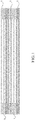
FIG. 1 is a schematic diagram of a grating manufactured according to a first example of the present disclosure. -
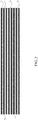
FIG. 2 is a schematic diagram of a grating manufactured according to a fourth example of the present disclosure. -
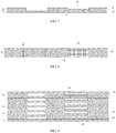
FIG. 3 schematically shows a side view of a grating element according to the first example of the present disclosure. -
FIG. 4 schematically shows a front view of the grating element according to the first example of the present disclosure. -
FIG. 5 and FIG. 6 schematically show side views of grating elements manufactured with sheets having different thicknesses according to the first example of the present disclosure. -
FIG. 7 is a schematic diagram of a grating manufactured according to a second example of the present disclosure. -
FIG. 8 schematically shows a side view of a grating element according to the second example of the present disclosure. -
FIG. 9 schematically shows a front view of grating elements according to the second example of the present disclosure. -
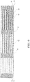
FIG. 10 is a schematic diagram of a grating manufactured according to a third example of the present disclosure. -
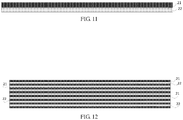
FIG. 11 schematically shows a side view of a grating element according to the fourth example of the present disclosure. -
FIG. 12 is a structural schematic diagram of a grating manufactured according to the fourth example of the present disclosure. - Exemplary embodiments will be described in detail with reference to the drawings. However, the present disclosure should not be taken to limit the invention to the specific embodiments shown, but are for explanation and understanding only.
- As shown in
FIG. 1 , the present disclosure provides a grating, including a plurality of stackedgrating elements 1, wherein thegrating elements 1 are stacked to form a grid. Thegrating element 1 includes afirst sheet second sheet second sheet first sheet first sheet first sheet - As shown in
FIG. 3 and FIG. 4 , thegrating element 1 includes afirst sheet 11 andsecond sheets 12. Thesecond sheet 12 has a length smaller than that of thefirst sheet 11, and at least twosecond sheets 12 are stacked at two ends on an identical surface of thefirst sheet 11 in a length direction of thefirst sheet 11, such that a grating slit is formed between adjacentfirst sheets 11. - As shown in
FIGs. 1 ,3 and 4 , according to an embodiment of the present disclosure, thegrating element 1 is formed of sheets having two different lengths, wherein thefirst sheet 11 and thesecond sheet 12 have different lengths. The twosecond sheets 12 are stacked at two ends on the identical surface of thefirst sheet 11. In this example, thefirst sheet 11 has a thickness same with or different from that of thesecond sheets 12. The thickness of thefirst sheet 11 determines a width of grating line, and the thickness of thesecond sheet 12 determines a width of grating slit.FIG. 1 shows a grating formed fromgrating elements 1 composed offirst sheets 11 andsecond sheets 12 having the same thickness according to the present disclosure, wherein the grating lines and the grating slits have same widths. Gratings with different duty ratios can be manufactured by adjusting the thicknesses of thefirst sheets 11 and thesecond sheets 12. The thicknesses of the first sheets and the second sheets can be preferably ranged from 0.001 to 3 millimeters. - As shown in
FIG. 5 , thefirst sheet 11 has a thickness smaller than that of thesecond sheets 12 in this example. In the grating formed from thegrating elements 1 in this example, the grating line has a width smaller than that of the grating slit. According to the present disclosure, the grating slit is formed between adjacentfirst sheets 11. In order to prevent deformation of the first sheets when the grating is formed from multiplegrating elements 1, the grating slits are filled with a thin material, which is pervious to radiation. - As shown in
FIG. 6 , thefirst sheet 11 has a thickness larger than that of thesecond sheet 12 in this example. In the grating formed from thegrating elements 1 in this example, the grating line has a width larger than that of the grating slit. - As shown in
FIGs. 7 to 9 , this example is substantially same as example 1, but differs in that in this example, thegrating element 1 is formed from sheets having three different lengths. Thefirst sheet 11 and thesecond sheet 12 have different lengths. The grating element further includes athird sheet 13, which has a length smaller than that of thefirst sheet 11. At least threesecond sheets 12 are stacked at two ends and a middle position on an identical surface of thefirst sheet 11 in a length direction of thefirst sheet 11. Thethird sheet 13 is stacked at thefirst sheet 11 between two of thesecond sheets 12. The length of thethird sheet 13 may be determined according to a length of a gap formed by thefirst sheet 11 and thesecond sheets 12. The length of thethird sheet 13 may be the same with the length of the gap formed by thefirst sheet 11 and thesecond sheets 12. If the gap formed by thefirst sheet 11 and thesecond sheets 12 has a length same with that of thesecond sheet 12, the length of thethird sheet 13 may be as also same with that of thesecond sheet 12. As shown inFIG. 9 , in order to form a grating structure having another duty ratio in a same grating, the thickness of thethird sheet 13 should be adjusted accordingly. When thethird sheet 13 is stacked at thefirst sheet 11 between two of thesecond sheets 12, the thickness of thethird sheet 13 is smaller than that of thesecond sheet 12. - It should be understood that the present disclosure is not limited to the above. According to the present disclosure, gratings having different duty ratios can also be further formed by combining more different sheets. As shown in
FIG. 10 , this example is substantially same as example 1, but differs in that in this example, thegrating element 1 is formed of four kinds of different sheets, wherein afourth sheet 14 is further provided. At least foursecond sheets 12 are stacked on an identical surface of thefirst sheet 11 in a length direction of thefirst sheet 11. Thethird sheet 13 is stacked at thefirst sheet 11 between two of thesecond sheets 12. Thefourth sheet 14 is further stacked at thethird sheet 13. Onefirst sheet 11, foursecond sheets 12, twothird sheets 13 and onefourth sheet 14 conjointly form thegrating element 1, and several stackedgrating elements 1 form a grating having various duty ratios. It should be understood that according to the above examples of stacking different sheets to form the grating, other gratings having various duty ratios can be further formed. - In the present disclosure, the
first sheet 11 and thesecond sheet 12 of thegrating element 1 are sheets almost impervious to radiation, e.g., sheets made of a high-density material, preferably tungsten alloy sheets. As each sheet of thegrating element 1 according to the present disclosure has a certain width, and the grating formed from thegrating elements 1 has a thickness consistent with the widths of the sheets, and the grating according to the present disclosure can be used along with high-energy X-rays. Existing grating manufactured with chemical methods have small thickness, and thus cannot be applied with high-energy X-rays. In the present disclosure, sheets are stacked to form uniform slits and there is no limitation on width of sheet and thus thickness of grating. Accordingly, the grating can be used for high-energy radiations, and the independently formed sheets have good toughness and strength. The grating elements according to the present disclosure can be bonded with adhesives or compressed with tools to be assembled into a grating. - As shown in
FIGs. 11 and 12 , this example is substantially same as example 1, but differs in that thesecond sheet 22 has a same length with thefirst sheet 21, thefirst sheet 21 is almost impervious to radiation, and thesecond sheet 22 is pervious to radiation. It should be noted here that the thicknesses of thefirst sheet 21 and thesecond sheet 22 in this example may be changed from the described solution according to actual needs, and thefirst sheet 21 may have a thickness same with or different from that of thesecond sheet 22. Thefirst sheets 21 and the second sheets having different thicknesses may form a grating having different grating slits. Moreover, other implementations can be obtained by combining example 4 with examples 1-3. For the sake of briefness, the other implementations are not redundantly described herein. - In conclusion, the grating and the radiation imaging device according to the present disclosure stack the sheets having different specifications together to form the grating with uniform grating slits, such that there is no limitation on the thickness of the grating and the grating can be used along with high-energy radiations.
- It should be noted that the above embodiments are merely provided for describing the technical solutions of the present invention, but not intended to limit the present invention. It should be understood by those of ordinary skill in the art that various alternations and modifications may be made without departing from the spirit and scope of the technical solutions of the embodiments of the present invention. Such equivalent embodiments are intended to be within the scope of the invention. The scope of the invention is defined by the accompanying claims.
Claims (14)
- A grating, characterized in that, comprising:a plurality of stacked grating elements, wherein the grating elements are stacked to form a grid;the grating element comprises a first sheet and a second sheet having two parallel planes; the second sheet is stacked at the first sheet in a length direction of the first sheet; andthe first sheet is almost impervious to radiation.
- The grating according to claim 1, characterized in that, the second sheet has a length smaller than that of the first sheet, and there are at least two second sheets;
the second sheets are stacked at two ends on an identical surface of the first sheet in the length direction of the first sheet, such that a grating slit is formed between adjacent first sheets. - The grating according to claim 2, characterized in that, the grating slit is filled with a material pervious to radiation.
- The grating according to claim 2, characterized in that, the first sheet has a thickness different from that of the second sheet.
- The grating according to claim 2, characterized in that, each of the first sheet and the second sheet has a thickness of 0.001 to 3 millimeters.
- The grating according to claim 2, characterized in that, the grating element further comprises a third sheet;
the third sheet has a length smaller than that of the first sheet, and at least three second sheets are stacked at the two ends and a middle position of an identical surface of the first sheet in the length direction of the first sheet; and
the third sheet is stacked on the first sheet between two of the second sheets. - The grating according to claim 6, characterized in that, the third sheet has a thickness smaller than that of the second sheet.
- The grating according to claim 1, characterized in that, the second sheet has a length same with that of the first sheet; and
the second sheet is pervious to radiation. - The grating according to claim 8, characterized in that, the first sheet has a thickness different from that of the second sheet.
- The grating according to claim 8, characterized in that, each of the first sheet and the second sheet has a thickness of 0.001 to 3 millimeters.
- The grating according to any of claims 1 to 10, characterized in that, the first sheet is a high-density sheet.
- The grating according to claim 11, characterized in that, the first sheet is a tungsten alloy sheet.
- The grating according to claim 12, characterized in that, the grating elements are bonded with adhesives or compressed with tools to be assembled into the grating.
- A radiation imaging device, characterized in that, comprising the grating according to any of claims 1 to 13.
Applications Claiming Priority (2)
| Application Number | Priority Date | Filing Date | Title |
|---|---|---|---|
| CN201510568450.5A CN105139913B (en) | 2015-09-08 | 2015-09-08 | A kind of grating and radiation imaging apparatus |
| PCT/CN2016/093274 WO2017041602A1 (en) | 2015-09-08 | 2016-08-04 | Grating and radiation imaging device |
Publications (3)
| Publication Number | Publication Date |
|---|---|
| EP3349220A1 true EP3349220A1 (en) | 2018-07-18 |
| EP3349220A4 EP3349220A4 (en) | 2019-05-01 |
| EP3349220B1 EP3349220B1 (en) | 2026-04-08 |
Family
ID=54725230
Family Applications (1)
| Application Number | Title | Priority Date | Filing Date |
|---|---|---|---|
| EP16843540.2A Active EP3349220B1 (en) | 2015-09-08 | 2016-08-04 | Grating and radiation imaging device |
Country Status (4)
| Country | Link |
|---|---|
| US (1) | US10643759B2 (en) |
| EP (1) | EP3349220B1 (en) |
| CN (1) | CN105139913B (en) |
| WO (1) | WO2017041602A1 (en) |
Families Citing this family (3)
| Publication number | Priority date | Publication date | Assignee | Title |
|---|---|---|---|---|
| CN105139913B (en) * | 2015-09-08 | 2017-10-13 | 清华大学 | A kind of grating and radiation imaging apparatus |
| CN107093487B (en) * | 2017-04-25 | 2023-06-27 | 中国科学院深圳先进技术研究院 | Manufacturing method of high-density grating |
| CN111053977B (en) * | 2019-12-20 | 2022-08-16 | 上海联影医疗科技股份有限公司 | Multi-leaf collimator and radiotherapy device |
Family Cites Families (20)
| Publication number | Priority date | Publication date | Assignee | Title |
|---|---|---|---|---|
| JPS53138294A (en) * | 1977-05-10 | 1978-12-02 | Toppan Printing Co Ltd | Xxray camera grid and method of producing same |
| US4414679A (en) * | 1982-03-01 | 1983-11-08 | North American Philips Corporation | X-Ray sensitive electrophoretic imagers |
| JPH07119837B2 (en) * | 1990-05-30 | 1995-12-20 | 株式会社日立製作所 | CT device, transmission device, and X-ray generator |
| JP2000217812A (en) * | 1999-01-27 | 2000-08-08 | Fuji Photo Film Co Ltd | Scattered-beam eliminating grid and manufacture therefor |
| DE10151562B4 (en) * | 2001-10-23 | 2004-07-22 | Siemens Ag | Arrangement of x-ray or gamma detector and anti-scatter grid or collimator |
| DE10241424B4 (en) * | 2002-09-06 | 2004-07-29 | Siemens Ag | Scattered radiation grid or collimator and method of manufacture |
| US20100006781A1 (en) * | 2006-08-25 | 2010-01-14 | Shimadzu Corporation | Hollow grid and manufacturing method thereof |
| WO2010018617A1 (en) * | 2008-08-11 | 2010-02-18 | 株式会社島津製作所 | Radiation grid and radiographic imaging apparatus having same |
| DE102009019647B4 (en) * | 2009-04-30 | 2014-07-10 | Siemens Aktiengesellschaft | Diffraction grating and method of manufacture |
| JP5660910B2 (en) * | 2010-03-30 | 2015-01-28 | 富士フイルム株式会社 | Method for manufacturing grid for radiographic imaging |
| JP2012093117A (en) * | 2010-10-25 | 2012-05-17 | Fujifilm Corp | Grid for photographing radiation image, manufacturing method thereof, and radiation image photographing system |
| JP2012112882A (en) * | 2010-11-26 | 2012-06-14 | Fujifilm Corp | Grid for radiographic imaging, manufacturing method thereof, and radiographic imaging system |
| CN201965938U (en) * | 2011-01-14 | 2011-09-07 | 沈阳航天新阳机电有限责任公司 | X-ray collimating grating of medical CT machine |
| JP5714968B2 (en) * | 2011-04-15 | 2015-05-07 | 株式会社日立ハイテクサイエンス | Diffraction grating for X-ray Talbot interferometer, manufacturing method thereof, and X-ray Talbot interferometer |
| DE102011080608B4 (en) * | 2011-08-08 | 2014-02-13 | Siemens Aktiengesellschaft | Method for producing an X-ray scattered radiation grid and X-ray scattered radiation grid |
| CN103901516B (en) * | 2012-12-26 | 2016-06-15 | 清华大学 | The preparation method of grating |
| CN203787096U (en) * | 2014-03-07 | 2014-08-20 | 上海联影医疗科技有限公司 | Multi-leaf collimator and multi-leaf collimator device |
| JP6448206B2 (en) * | 2014-03-31 | 2019-01-09 | 株式会社フジキン | Multilayer X-ray grid, manufacturing apparatus and manufacturing method thereof |
| CN105139913B (en) * | 2015-09-08 | 2017-10-13 | 清华大学 | A kind of grating and radiation imaging apparatus |
| CN204926815U (en) * | 2015-09-08 | 2015-12-30 | 清华大学 | Grating and radiation image device |
-
2015
- 2015-09-08 CN CN201510568450.5A patent/CN105139913B/en active Active
-
2016
- 2016-08-04 EP EP16843540.2A patent/EP3349220B1/en active Active
- 2016-08-04 WO PCT/CN2016/093274 patent/WO2017041602A1/en not_active Ceased
-
2017
- 2017-11-03 US US15/802,473 patent/US10643759B2/en active Active
Also Published As
| Publication number | Publication date |
|---|---|
| US10643759B2 (en) | 2020-05-05 |
| US20180075938A1 (en) | 2018-03-15 |
| EP3349220A4 (en) | 2019-05-01 |
| CN105139913A (en) | 2015-12-09 |
| EP3349220B1 (en) | 2026-04-08 |
| WO2017041602A1 (en) | 2017-03-16 |
| CN105139913B (en) | 2017-10-13 |
Similar Documents
| Publication | Publication Date | Title |
|---|---|---|
| US8243879B2 (en) | Source grating for X-rays, imaging apparatus for X-ray phase contrast image and X-ray computed tomography system | |
| EP1081457B1 (en) | Optical position measuring device | |
| US10643759B2 (en) | Grating and radiation imaging device | |
| EP2827339A1 (en) | Source grating, interferometer, and object information acquisition system | |
| EP1399927B1 (en) | Multi-layer grating for monochromatization and spectroscopy | |
| JP2008197593A (en) | Transmission type diffraction grating for x-ray, x-ray talbot interferometer and x-ray imaging apparatus | |
| DE102011052995A1 (en) | Displacement detecting device | |
| EP3059554B1 (en) | Optical positioning device | |
| EP3224677A1 (en) | Mirror, in particular collector mirror for microlithography | |
| Seiboth et al. | Hard x-ray nanofocusing by refractive lenses of constant thickness | |
| DE102018210382A1 (en) | Gauging Sensor | |
| DE102016200847A1 (en) | Optical position measuring device | |
| JP5208224B2 (en) | Radiography apparatus and radiation imaging system | |
| DE102016210434A1 (en) | Optical position measuring device | |
| WO2015033552A4 (en) | Absorption grating and talbot interferometer | |
| EP2869034B1 (en) | Position sensing device | |
| Jark et al. | On the feasibility of large-aperture Fresnel lenses for the microfocusing of hard X-rays | |
| CN113874961A (en) | Stabilized grating structure | |
| CN204926815U (en) | Grating and radiation image device | |
| CN102903412B (en) | Multilayer total internal reflection optic and production and preparation method thereof | |
| EP3045873B1 (en) | Optical positioning device | |
| DE112014001977B4 (en) | Device for interferential distance measurement | |
| US7386098B2 (en) | Fine geometry X-ray collimator and construction method | |
| JP2016001264A (en) | Grating, grating unit, curved grating and x-ray imaging device | |
| Vitoratou et al. | X-Ray Pinhole Camera Spatial Resolution Using High Aspect Ratio LIGA Pinhole Apertures |
Legal Events
| Date | Code | Title | Description |
|---|---|---|---|
| STAA | Information on the status of an ep patent application or granted ep patent |
Free format text: STATUS: THE INTERNATIONAL PUBLICATION HAS BEEN MADE |
|
| PUAI | Public reference made under article 153(3) epc to a published international application that has entered the european phase |
Free format text: ORIGINAL CODE: 0009012 |
|
| STAA | Information on the status of an ep patent application or granted ep patent |
Free format text: STATUS: REQUEST FOR EXAMINATION WAS MADE |
|
| 17P | Request for examination filed |
Effective date: 20170829 |
|
| AK | Designated contracting states |
Kind code of ref document: A1 Designated state(s): AL AT BE BG CH CY CZ DE DK EE ES FI FR GB GR HR HU IE IS IT LI LT LU LV MC MK MT NL NO PL PT RO RS SE SI SK SM TR |
|
| AX | Request for extension of the european patent |
Extension state: BA ME |
|
| DAV | Request for validation of the european patent (deleted) | ||
| DAX | Request for extension of the european patent (deleted) | ||
| A4 | Supplementary search report drawn up and despatched |
Effective date: 20190403 |
|
| RIC1 | Information provided on ipc code assigned before grant |
Ipc: G02B 5/18 20060101AFI20190328BHEP Ipc: G21K 1/06 20060101ALI20190328BHEP Ipc: G21K 1/02 20060101ALI20190328BHEP |
|
| STAA | Information on the status of an ep patent application or granted ep patent |
Free format text: STATUS: EXAMINATION IS IN PROGRESS |
|
| 17Q | First examination report despatched |
Effective date: 20210917 |
|
| GRAP | Despatch of communication of intention to grant a patent |
Free format text: ORIGINAL CODE: EPIDOSNIGR1 |
|
| STAA | Information on the status of an ep patent application or granted ep patent |
Free format text: STATUS: GRANT OF PATENT IS INTENDED |
|
| INTG | Intention to grant announced |
Effective date: 20251118 |
|
| GRAS | Grant fee paid |
Free format text: ORIGINAL CODE: EPIDOSNIGR3 |
|
| GRAA | (expected) grant |
Free format text: ORIGINAL CODE: 0009210 |
|
| STAA | Information on the status of an ep patent application or granted ep patent |
Free format text: STATUS: THE PATENT HAS BEEN GRANTED |
|
| AK | Designated contracting states |
Kind code of ref document: B1 Designated state(s): AL AT BE BG CH CY CZ DE DK EE ES FI FR GB GR HR HU IE IS IT LI LT LU LV MC MK MT NL NO PL PT RO RS SE SI SK SM TR |
|
| REG | Reference to a national code |
Ref country code: CH Ref legal event code: F10 Free format text: ST27 STATUS EVENT CODE: U-0-0-F10-F00 (AS PROVIDED BY THE NATIONAL OFFICE) Effective date: 20260408 Ref country code: GB Ref legal event code: FG4D |
|
| REG | Reference to a national code |
Ref country code: NL Ref legal event code: FP |
|
| REG | Reference to a national code |
Ref country code: DE Ref legal event code: R096 Ref document number: 602016095166 Country of ref document: DE |