EP3349048A1 - Inspection devices and methods for detecting a firearm in a luggage - Google Patents
Inspection devices and methods for detecting a firearm in a luggage Download PDFInfo
- Publication number
- EP3349048A1 EP3349048A1 EP18151062.9A EP18151062A EP3349048A1 EP 3349048 A1 EP3349048 A1 EP 3349048A1 EP 18151062 A EP18151062 A EP 18151062A EP 3349048 A1 EP3349048 A1 EP 3349048A1
- Authority
- EP
- European Patent Office
- Prior art keywords
- firearm
- network
- neural network
- candidate regions
- detection
- Prior art date
- Legal status (The legal status is an assumption and is not a legal conclusion. Google has not performed a legal analysis and makes no representation as to the accuracy of the status listed.)
- Granted
Links
- 238000000034 method Methods 0.000 title claims abstract description 44
- 238000007689 inspection Methods 0.000 title claims abstract description 27
- 238000001514 detection method Methods 0.000 claims abstract description 81
- 230000005540 biological transmission Effects 0.000 claims abstract description 41
- 238000013528 artificial neural network Methods 0.000 claims abstract description 29
- 238000013527 convolutional neural network Methods 0.000 claims description 29
- 238000012549 training Methods 0.000 claims description 23
- 230000008569 process Effects 0.000 description 14
- 238000010586 diagram Methods 0.000 description 13
- 238000000605 extraction Methods 0.000 description 7
- 238000007781 pre-processing Methods 0.000 description 7
- 239000011159 matrix material Substances 0.000 description 5
- 238000013480 data collection Methods 0.000 description 4
- 238000005516 engineering process Methods 0.000 description 4
- 238000004422 calculation algorithm Methods 0.000 description 3
- 238000004891 communication Methods 0.000 description 3
- 238000004590 computer program Methods 0.000 description 3
- 238000013135 deep learning Methods 0.000 description 3
- 238000012545 processing Methods 0.000 description 3
- 230000005855 radiation Effects 0.000 description 3
- 230000006870 function Effects 0.000 description 2
- 230000004927 fusion Effects 0.000 description 2
- 238000003384 imaging method Methods 0.000 description 2
- 238000003491 array Methods 0.000 description 1
- 230000008901 benefit Effects 0.000 description 1
- 238000004364 calculation method Methods 0.000 description 1
- 238000005336 cracking Methods 0.000 description 1
- 238000013136 deep learning model Methods 0.000 description 1
- 230000001066 destructive effect Effects 0.000 description 1
- 230000000694 effects Effects 0.000 description 1
- 239000000835 fiber Substances 0.000 description 1
- 231100000225 lethality Toxicity 0.000 description 1
- 239000004973 liquid crystal related substance Substances 0.000 description 1
- 239000000463 material Substances 0.000 description 1
- 230000007246 mechanism Effects 0.000 description 1
- 238000012986 modification Methods 0.000 description 1
- 230000004048 modification Effects 0.000 description 1
- 238000010606 normalization Methods 0.000 description 1
- 238000007639 printing Methods 0.000 description 1
- 238000011160 research Methods 0.000 description 1
Images


Classifications
-
- G01V5/22—
-
- G—PHYSICS
- G01—MEASURING; TESTING
- G01N—INVESTIGATING OR ANALYSING MATERIALS BY DETERMINING THEIR CHEMICAL OR PHYSICAL PROPERTIES
- G01N23/00—Investigating or analysing materials by the use of wave or particle radiation, e.g. X-rays or neutrons, not covered by groups G01N3/00 – G01N17/00, G01N21/00 or G01N22/00
- G01N23/02—Investigating or analysing materials by the use of wave or particle radiation, e.g. X-rays or neutrons, not covered by groups G01N3/00 – G01N17/00, G01N21/00 or G01N22/00 by transmitting the radiation through the material
- G01N23/04—Investigating or analysing materials by the use of wave or particle radiation, e.g. X-rays or neutrons, not covered by groups G01N3/00 – G01N17/00, G01N21/00 or G01N22/00 by transmitting the radiation through the material and forming images of the material
-
- G—PHYSICS
- G06—COMPUTING; CALCULATING OR COUNTING
- G06F—ELECTRIC DIGITAL DATA PROCESSING
- G06F18/00—Pattern recognition
- G06F18/20—Analysing
- G06F18/21—Design or setup of recognition systems or techniques; Extraction of features in feature space; Blind source separation
- G06F18/214—Generating training patterns; Bootstrap methods, e.g. bagging or boosting
-
- G—PHYSICS
- G06—COMPUTING; CALCULATING OR COUNTING
- G06F—ELECTRIC DIGITAL DATA PROCESSING
- G06F18/00—Pattern recognition
- G06F18/20—Analysing
- G06F18/24—Classification techniques
-
- G—PHYSICS
- G06—COMPUTING; CALCULATING OR COUNTING
- G06N—COMPUTING ARRANGEMENTS BASED ON SPECIFIC COMPUTATIONAL MODELS
- G06N3/00—Computing arrangements based on biological models
- G06N3/02—Neural networks
- G06N3/04—Architecture, e.g. interconnection topology
-
- G—PHYSICS
- G06—COMPUTING; CALCULATING OR COUNTING
- G06N—COMPUTING ARRANGEMENTS BASED ON SPECIFIC COMPUTATIONAL MODELS
- G06N3/00—Computing arrangements based on biological models
- G06N3/02—Neural networks
- G06N3/04—Architecture, e.g. interconnection topology
- G06N3/045—Combinations of networks
-
- G—PHYSICS
- G06—COMPUTING; CALCULATING OR COUNTING
- G06N—COMPUTING ARRANGEMENTS BASED ON SPECIFIC COMPUTATIONAL MODELS
- G06N3/00—Computing arrangements based on biological models
- G06N3/02—Neural networks
- G06N3/08—Learning methods
-
- G—PHYSICS
- G06—COMPUTING; CALCULATING OR COUNTING
- G06T—IMAGE DATA PROCESSING OR GENERATION, IN GENERAL
- G06T5/00—Image enhancement or restoration
- G06T5/50—Image enhancement or restoration by the use of more than one image, e.g. averaging, subtraction
-
- G—PHYSICS
- G06—COMPUTING; CALCULATING OR COUNTING
- G06T—IMAGE DATA PROCESSING OR GENERATION, IN GENERAL
- G06T7/00—Image analysis
- G06T7/0002—Inspection of images, e.g. flaw detection
- G06T7/0004—Industrial image inspection
- G06T7/001—Industrial image inspection using an image reference approach
-
- G—PHYSICS
- G06—COMPUTING; CALCULATING OR COUNTING
- G06T—IMAGE DATA PROCESSING OR GENERATION, IN GENERAL
- G06T7/00—Image analysis
- G06T7/70—Determining position or orientation of objects or cameras
- G06T7/73—Determining position or orientation of objects or cameras using feature-based methods
- G06T7/74—Determining position or orientation of objects or cameras using feature-based methods involving reference images or patches
-
- G—PHYSICS
- G06—COMPUTING; CALCULATING OR COUNTING
- G06T—IMAGE DATA PROCESSING OR GENERATION, IN GENERAL
- G06T2207/00—Indexing scheme for image analysis or image enhancement
- G06T2207/10—Image acquisition modality
- G06T2207/10116—X-ray image
-
- G—PHYSICS
- G06—COMPUTING; CALCULATING OR COUNTING
- G06T—IMAGE DATA PROCESSING OR GENERATION, IN GENERAL
- G06T2207/00—Indexing scheme for image analysis or image enhancement
- G06T2207/20—Special algorithmic details
- G06T2207/20212—Image combination
- G06T2207/20221—Image fusion; Image merging
-
- G—PHYSICS
- G06—COMPUTING; CALCULATING OR COUNTING
- G06T—IMAGE DATA PROCESSING OR GENERATION, IN GENERAL
- G06T2207/00—Indexing scheme for image analysis or image enhancement
- G06T2207/30—Subject of image; Context of image processing
- G06T2207/30108—Industrial image inspection
- G06T2207/30112—Baggage; Luggage; Suitcase
-
- G—PHYSICS
- G06—COMPUTING; CALCULATING OR COUNTING
- G06T—IMAGE DATA PROCESSING OR GENERATION, IN GENERAL
- G06T2207/00—Indexing scheme for image analysis or image enhancement
- G06T2207/30—Subject of image; Context of image processing
- G06T2207/30232—Surveillance
Definitions
- the present disclosure relates to radiation inspection technologies, and more particularly, to an inspection device and a method for detecting a firearm in a luggage.
- Firearms are weapons having direct lethality and great destructive power, and if firearms are illegally carried, it may cause great potential dangers and social hidden dangers, and have a direct impact on social stability and people's lives and property.
- an inspection device and a method for detecting a firearm in a luggage are proposed.
- a method for detecting a firearm in a luggage comprising steps of: performing X-ray inspection on the luggage to obtain a transmission image; determining a plurality of candidate regions in the transmission image using a trained firearm detection neural network; and classifying the plurality of candidate regions using the detection neural network to determine whether there is a firearm included in the transmission image.
- the method further comprises steps of: calculating a confidence level of including a firearm in each candidate region, and determining that there is a firearm included in a candidate region in a case that a confidence level for the candidate region is greater than a specific threshold.
- the method further comprises steps of: in a case that the same firearm is included in a plurality of candidate regions, marking and fusing images of the firearm in various candidate regions to obtain a position of the firearm.
- the firearm detection neural network is trained by the following operations: creating sample transmission images of firearms; fusing a Region Proposal Network (RPN) and a conventional layer of a Convolutional Neural Network (CNN) to obtain an initial detection network; and training the initial detection network using the sample transmission images to obtain the firearm detection neural network.
- RPN Region Proposal Network
- CNN Convolutional Neural Network
- the step of training the initial detection network comprises: adjusting the initial detection network using a plurality of sample candidate regions determined from the sample transmission images in a case of not sharing data of the convolutional layer between the RPN and the CNN; training the RPN in a case of sharing the data of the convolutional layer between the RPN and the CNN; and adjusting the initial detection network to converge in a case of keeping sharing the data of the convolutional layer between the RPN and the CNN unchanged to obtain the firearm detection neural network.
- the step of training the initial detection network further comprises: deleting a sample candidate region in the plurality of sample candidate regions which has an overlapped area less than a threshold with a rectangular block which is manually marked for a firearm.
- an inspection device comprising: an X-ray inspection system configured to perform X-ray inspection on a luggage to obtain a transmission image; a memory having the transmission image stored thereon; and a processor configured to: determine a plurality of candidate regions in the transmission image using a trained firearm detection neural network; and classify the plurality of candidate regions using the firearm detection neural network to determine whether there is a firearm included in the transmission image.
- the processor is configured to calculate a confidence level of including a firearm in each candidate region, and determine that there is a firearm included in a candidate region in a case that a confidence level for the candidate region is greater than a specific threshold.
- the processor is configured to mark and fuse images of the firearm in various candidate regions to obtain a position of the firearm in a case that the same firearm is included in a plurality of candidate regions.
- the memory has sample transmission images of firearms stored thereon, and the processor is configured to train the firearm detection neural network by the following operations: fusing a Region Proposal Network (RPN) and a conventional layer of a Convolutional Neural Network (CNN) to obtain an initial detection network; and training the initial detection network using the sample transmission images to obtain the firearm detection neural network.
- RPN Region Proposal Network
- CNN Convolutional Neural Network
- the embodiments of the present disclosure propose a method for detecting a firearm in a luggage.
- a plurality of candidate regions in a transmission image are determined using a trained firearm detection neural network, and then the plurality of candidate regions are classified using the firearm detection neural network to determine whether there is a firearm included in the transmission image. In this way, it is more accurately detected whether there is a firearm included in a luggage.
- the automatic firearm detection technology includes three steps of 1) creating a firearm detection database, 2) automatically creating an detection model, and 3) automatically detecting a firearm.
- creating a firearm detection database comprises three steps of image acquisition, image preprocessing and region of interest extraction.
- Automatically detecting a firearm primarily comprises three steps of image preprocessing, judgment and marking a suspicious region.
- a firearms detection database is created, which includes three steps of image acquisition, image preprocessing and region of interest extraction.
- Image acquisition includes, for example, collecting a considerable number of images of firearms from a small article machine, so that an image database includes images of different numbers of firearms which are placed in various forms.
- the image preprocessing specifically involves, for example, a normalization process. Different scanning devices may obtain different images due to different energy/doses of ray sources and different sizes of detectors. In order to reduce this difference, the image may be normalized.
- the region of interest extraction involves manually marking positions of firearms in units of firearms in the scanned grayscale image and giving coordinates ( x , y , w , h ) of the firearms, where x and y represent coordinates of a lower left apex of a circumscribed rectangle of a firearm, w represents a width of the circumscribed rectangle, and h represents a height of the circumscribed rectangle.
- a detection model is automatically created using the deep learning theory.
- a firearm is primarily detected using the deep learning theory.
- CNN Convolutional Neural Network
- CNN Convolutional Neural Network
- Candidate region extraction and CNN classification are performed using a CNN as an example in the embodiments of the present disclosure.
- the candidate region extraction uses a Region Proposal Network (RPN) to realize an end-to-end network for detecting a firearm.
- RPN Region Proposal Network
- a firearm detection process involves directly generating candidate regions using a trained CNN and classifying the candidate regions to determine whether there is a firearm in the candidate regions.
- a specific position of the firearm in the candidate regions is regressed to determine coordinates of the firearm, and a detection result marked in a rectangular block may be given.
- FIG. 1 illustrates a structural diagram of an inspection device according to an embodiment of the present disclosure.
- an inspection device 100 according to an embodiment of the present disclosure comprises an X-ray source 110, a detector 130, a data collection apparatus 150, a controller 140, and a computing device 160, and performs security inspection on an inspected object 120 such as a container truck etc., for example, judges whether there is a firearm included therein.
- the detector 130 and the data collection apparatus 150 are separately described in this embodiment, it should be understood by those skilled in the art that they may also be integrated together as an X-ray detection and data collection device.
- the X-ray source 110 may be an isotope, or may also be an X-ray machine, an accelerator, etc.
- the X-ray source 110 may be a single-energy ray source or a dual-energy ray source.
- transmission scanning is performed on the inspected object 120 through the X-ray source 110, the detector 150, the controller 140, and the computing device 160 to obtain detection data.
- an operator controls the controller 140 to transmit an instruction through a man-machine interface of the computing device 160 to instruct the X-ray source 110 to emit rays, which are transmitted through the inspected object 120 and are then received by the detector 130 and the data collection device 150.
- data is processed by the computing device 160 to obtain a transmission image and store the transmission image in a memory, then a plurality of candidate regions in the transmission image are determined using a trained firearm detection neural network, and the plurality of candidate regions are classified using the firearm detection neural network to determine whether there is a firearm included in the transmission image.
- Fig. 2 illustrates a structural diagram of the computing device illustrated in Fig. 1 .
- a signal detected by the detector 130 is collected by a data collector, and data is stored in a memory 161 through an interface unit 167 and a bus 163.
- a Read Only Memory (ROM) 162 stores configuration information and programs of a computer data processor.
- a Random Access Memory (RAM) 163 is configured to temporarily store various data when a processor 165 is in operation.
- computer programs for performing data processing such as an image processing program, a firearm recognition convolutional network program etc., are also stored in the memory 161.
- the internal bus 163 connects the memory 161, the ROM 162, the RAM 163, an input apparatus 164, the processor 165, a display apparatus 166, and the interface unit 167 described above.
- the processor 165 in the computer may be configured to execute a software program to calculate a confidence level of including a firearm in each candidate region, and determine that there is a firearm included in the candidate region if the confidence level is greater than a specific threshold.
- the processor 165 may be configured to execute a software program to mark an image of a firearm in each candidate region in a case that the same firearm is included in a plurality of candidate regions, and fuse images of the firearm in various candidate regions, to obtain a position of the firearm.
- a method for automatically detecting a firearm is mainly based on the deep learning theory, and performs training using a CNN network to obtain a detection model.
- a convolutional neural network is used to automatically detect a firearm region in a radiation image.
- a firearm detection database needs to be created to train the convolutional network.
- Fig. 3 is a diagram illustrating a process of creating a database for training according to an embodiment of the present disclosure.
- a firearm detection database is primarily created through three steps which are image collection, image pre-processing, and Region Of Interest (ROI) extraction.
- ROI Region Of Interest
- step S310 sample images are acquired. For example, a considerable number of images of firearms from a small article machine are collected, so that an image database includes images of different numbers of firearms which are placed in various forms to obtain a firearm image library ⁇ ⁇ . The diversity of the samples is enriched, so that a firearm detection algorithm according to the present disclosure has a generalization capability.
- the images are preprocessed.
- the images may be normalized while acquiring the images.
- a normalized image X may be obtained by scaling a resolution of X to 5 mm/pixel according to physical parameters of a scanning device and performing grayscale stretching on X.
- positions of firearms are manually marked in units of firearms and coordinates ( x , y , w , h ) of the firearms are given, where x and y represent coordinates of a lower left apex of a circumscribed rectangle of a firearm, w represents a width of the circumscribed rectangle, and h represents a height of the circumscribed rectangle.
- Fig. 4 is a diagram illustrating a process of creating a firearm detection network model according to an embodiment of the present disclosure.
- a region proposal method is adopted, and candidate region extraction is combined with CNN classification by using a RPN network to create an end-to-end firearm detection network.
- sample transmission images of firearms are acquired.
- the sample transmission images are obtained from the firearm sample image database created above.
- an initial detection network is obtained by fusing the RPN and a convolutional layer of a CNN, and then in step S430, the initial detection network is trained by using the sample transmission images to obtain a firearm detection neural network.
- a RPN module and a CNN detection module are used in the present algorithm.
- the fusion training method is different from the alternative training method in that in the process of reverse regression, a layer shared by the two networks combines a loss of the RPN network with a loss of the CNN detection network together.
- Fig. 5 illustrates an example of the alternate training method.
- a specific training process of the alternate training method is as follows.
- step S510 initialization is performed. Firstly, an input image is scaled to a size of less than 600 pixels in the short side, and weights in the RPN network and the CNN detection network are initialized by a pre-trained model, wherein initial biases of a visible layer and a hidden layer are a and b, an initial weight matrix is W , and increments of the biases and the weight matrix are ⁇ a , ⁇ b and ⁇ W .
- a pre-trained model to initialize the network is that the model is nearly optimal to some extent, and saves time and resources over random initialization.
- step S520 candidate regions are extracted.
- two branches of full connection layers are generated on this layer of features, which are a rectangular block classification layer and a rectangular block regression layer, and there are 2* k candidate regions and 4* k candidate regions on these two different layers respectively.
- step S530 positive and negative samples are marked.
- positive and negative samples are marked for the candidate regions using a marking rule as follows. When a portion of a rectangular block of a candidate region which is overlapped with a real value is greater than 0.7, the candidate region is marked as a positive sample, and when a portion of a rectangular block of a candidate region which is overlapped with the real value is less than 0.3, the candidate region is marked as a negative sample. Remaining candidate regions are discarded, and are not used for training.
- step S540 the obtained candidate regions are combined with the obtained CNN detection network to fine-tune the detection network.
- both networks do not share data of the convolutional layer.
- step 550 a trained network is used to initialize the RPN and train the RPN network.
- the data of the convolutional layer is fixed, and only a part of the network layer which belongs to the RPN is fine-tuned.
- both networks share the convolutional layer.
- step S560 sharing of the convolutional layer is kept unchanged, and the CNN detection network continues to be fine-tuned to update the biases and the weight matrix:
- Fig. 6 illustrates a schematic flowchart of a process of detecting a firearm according to an embodiment of the present disclosure.
- the firearm detection process is divided into two steps of image preprocessing and firearm detection.
- step S610 X-ray inspection is performed on a luggage using the inspection system illustrated in Fig. 1 to obtain a transmission image.
- the image may also be pre-processed in this step.
- the collected firearm image information is pre-processed using the above-mentioned image preprocessing method.
- the images may be normalized while acquiring the images. Specifically, assuming that an original two-dimensional image signal is X, a normalized image X may be obtained by scaling a resolution of X to 5 mm/pixel according to physical parameters of a scanning device and performing grayscale stretching on X.
- a plurality of candidate regions in the transmission image are determined using the trained firearm detection neural network.
- the resulting pre-processed firearm image is input into the detection network, which is a subset of networks created using a model, and a plurality of candidate regions are generated in the input image.
- the obtained plurality of candidate regions which include the same firearm are detected, and have different sizes.
- a plurality of candidate regions may be generated for each of the firearms.
- step S630 the plurality of candidate regions are classified using the firearm detection neural network to determine whether there is a firearm included in the transmission image. For example, firearm classification is performed in the candidate regions using the firearm detection neural network, and if a confidence level for a firearm in a region is greater than a specified threshold, for example, 0.9, it is considered that there is a firearm in this region.
- a specified threshold for example, 0.9
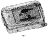
- Fig. 7 illustrates a diagram of detecting a firearm in a luggage according to an embodiment of the present disclosure. As shown in Fig. 7 , a rectangular block may be marked, and all candidate regions in which there is a firearm may finally be fused to obtain a final position of the firearm.
- the automatic firearm detection technology can detect a firearm from a scanned image of a small article machine, which can avoid the problems of detection vulnerability and inefficiency of manual image judgment using the traditional methods and is of great significance for cracking down on illegal carrying of firearms.
- ASICs Application Specific Integrated Circuits
- FPGAs Field Programmable Gate Arrays
- DSPs Digital Signal Processors
- ASICs Application Specific Integrated Circuits
- FPGAs Field Programmable Gate Arrays
- DSPs Digital Signal Processors
- those skilled in the art will recognize that some aspects of the embodiments disclosed herein, in whole or in part, may be equivalently implemented in integrated circuits, as one or more computer programs running on one or more computers (e.g., as one or more programs running on one or more computer systems), as one or more programs running on one or more processors (e.g., as one or more programs running on one or more microprocessors), as firmware, or as virtually any combination thereof, and that designing the circuitry and/or writing the code for the software and/or firmware would be well within the skill of those skilled in the art in ray of this disclosure.
- Examples of a signal bearing medium include, but are not limited to, the following: a recordable type medium such as a floppy disk, a hard disk drive, a Compact Disc (CD), a Digital Versatile Disk (DVD), a digital tape, a computer memory, etc.; and a transmission type medium such as a digital and/or an analog communication medium (e.g., a fiber optic cable, a waveguide, a wired communications link, a wireless communication link, etc.).
Abstract
Description
- The present disclosure relates to radiation inspection technologies, and more particularly, to an inspection device and a method for detecting a firearm in a luggage.
- Firearms are weapons having direct lethality and great destructive power, and if firearms are illegally carried, it may cause great potential dangers and social hidden dangers, and have a direct impact on social stability and people's lives and property. There is a large daily passenger flow in civil aviation, subway and rail transit systems, and the current manual detection is slow and relies heavily on the staff. Therefore, it is also the focus of attention today to improve a degree of automation and a detection speed of a system for detecting a firearm.
- There is currently no effective means of detecting a firearm. According to the research, firearms are mainly transported through a luggage. Radiation imaging achieves the purpose of non-invasive inspection by imaging cargos and a luggage. This technology has been widely used in places such as airports, stations, express sites etc., and is the most important means in the field of security inspection for prohibited articles. In the process of inspecting using a small article machine, although an image of the interior of a luggage has been obtained, the effect of manual judgment is unsatisfied since there is a wide variety of articles, image judgers have various experience levels and it is a low probability that dangerous articles such as firearms exist.
- In view of one or more of the problems in the related art, an inspection device and a method for detecting a firearm in a luggage are proposed.
- According to an aspect of the present disclosure, there is proposed a method for detecting a firearm in a luggage, comprising steps of: performing X-ray inspection on the luggage to obtain a transmission image; determining a plurality of candidate regions in the transmission image using a trained firearm detection neural network; and classifying the plurality of candidate regions using the detection neural network to determine whether there is a firearm included in the transmission image.
- According to an embodiment of the present disclosure, the method further comprises steps of: calculating a confidence level of including a firearm in each candidate region, and determining that there is a firearm included in a candidate region in a case that a confidence level for the candidate region is greater than a specific threshold.
- According to an embodiment of the present disclosure, the method further comprises steps of: in a case that the same firearm is included in a plurality of candidate regions, marking and fusing images of the firearm in various candidate regions to obtain a position of the firearm.
- According to an embodiment of the present disclosure, the firearm detection neural network is trained by the following operations: creating sample transmission images of firearms; fusing a Region Proposal Network (RPN) and a conventional layer of a Convolutional Neural Network (CNN) to obtain an initial detection network; and training the initial detection network using the sample transmission images to obtain the firearm detection neural network.
- According to an embodiment of the present disclosure, the step of training the initial detection network comprises: adjusting the initial detection network using a plurality of sample candidate regions determined from the sample transmission images in a case of not sharing data of the convolutional layer between the RPN and the CNN; training the RPN in a case of sharing the data of the convolutional layer between the RPN and the CNN; and adjusting the initial detection network to converge in a case of keeping sharing the data of the convolutional layer between the RPN and the CNN unchanged to obtain the firearm detection neural network.
- According to an embodiment of the present disclosure, the step of training the initial detection network further comprises: deleting a sample candidate region in the plurality of sample candidate regions which has an overlapped area less than a threshold with a rectangular block which is manually marked for a firearm.
- According to another aspect of the present disclosure, there is proposed an inspection device, comprising: an X-ray inspection system configured to perform X-ray inspection on a luggage to obtain a transmission image; a memory having the transmission image stored thereon; and a processor configured to: determine a plurality of candidate regions in the transmission image using a trained firearm detection neural network; and classify the plurality of candidate regions using the firearm detection neural network to determine whether there is a firearm included in the transmission image.
- According to an embodiment of the present disclosure, the processor is configured to calculate a confidence level of including a firearm in each candidate region, and determine that there is a firearm included in a candidate region in a case that a confidence level for the candidate region is greater than a specific threshold.
- According to an embodiment of the present disclosure, the processor is configured to mark and fuse images of the firearm in various candidate regions to obtain a position of the firearm in a case that the same firearm is included in a plurality of candidate regions.
- According to an embodiment of the present disclosure, the memory has sample transmission images of firearms stored thereon, and the processor is configured to train the firearm detection neural network by the following operations: fusing a Region Proposal Network (RPN) and a conventional layer of a Convolutional Neural Network (CNN) to obtain an initial detection network; and training the initial detection network using the sample transmission images to obtain the firearm detection neural network.
- With the above solutions, it is possible to determine more accurately whether there is a firearm included in a luggage. In other embodiments, after a firearm is detected using the above method, a label is marked in the image to prompt an image judger, thereby reducing the workload of manual image judgment.
- For a better understanding of the present disclosure, the present disclosure will be described in detail according to the following accompanying drawings:
-
Fig. 1 is a structural diagram of an inspection device according to an embodiment of the present disclosure; -
Fig. 2 is a diagram illustrating a structure of a computing device included in the inspection device illustrated inFig. 1 ; -
Fig. 3 is a diagram illustrating a process of creating a database for training according to an embodiment of the present disclosure; -
Fig. 4 is a diagram illustrating a process of creating a firearm detection network model; -
Fig. 5 is a schematic flowchart specifically illustrating creating a firearm detection network model according to an embodiment of the present disclosure; -
Fig. 6 illustrates a schematic flowchart of a process of detecting firearms according to an embodiment of the present disclosure; and -
Fig. 7 illustrates a diagram of detecting a firearm in a luggage according to an embodiment of the present disclosure. - The specific embodiments of the present disclosure will be described in detail below. It should be noted that the embodiments herein are used for illustration only, without limiting the present disclosure. In the description below, a number of specific details are explained to provide better understanding of the present disclosure. However, it is apparent to those skilled in the art that the present disclosure can be implemented without these specific details. In other instances, well known structures, materials or methods are not described specifically so as not to obscure the present disclosure.
- Throughout the specification, the reference to "one embodiment," "an embodiment," "one example" or "an example" means that the specific features, structures or properties described in conjunction with the embodiment or example are included in at least one embodiment of the present disclosure. Therefore, the phrases "in one embodiment," "in an embodiment," "in one example" or "in an example" occurred in various positions throughout the specification may not necessarily refer to the same embodiment or example. Furthermore, specific features, structures or properties may be combined into one or more embodiments or examples in any appropriate combination and/or sub-combination. Moreover, it should be understood by those skilled in the art that the term "and/or" used herein means any and all combinations of one or more listed items.
- In view of the problems in the related art, the embodiments of the present disclosure propose a method for detecting a firearm in a luggage. A plurality of candidate regions in a transmission image are determined using a trained firearm detection neural network, and then the plurality of candidate regions are classified using the firearm detection neural network to determine whether there is a firearm included in the transmission image. In this way, it is more accurately detected whether there is a firearm included in a luggage.
- The automatic firearm detection technology according to the embodiments of the present disclosure includes three steps of 1) creating a firearm detection database, 2) automatically creating an detection model, and 3) automatically detecting a firearm. Specifically, creating a firearm detection database comprises three steps of image acquisition, image preprocessing and region of interest extraction. Automatically detecting a firearm primarily comprises three steps of image preprocessing, judgment and marking a suspicious region.
- Before a firearm detection model is created, a firearms detection database is created, which includes three steps of image acquisition, image preprocessing and region of interest extraction. Image acquisition includes, for example, collecting a considerable number of images of firearms from a small article machine, so that an image database includes images of different numbers of firearms which are placed in various forms. The image preprocessing specifically involves, for example, a normalization process. Different scanning devices may obtain different images due to different energy/doses of ray sources and different sizes of detectors. In order to reduce this difference, the image may be normalized. In addition, the region of interest extraction involves manually marking positions of firearms in units of firearms in the scanned grayscale image and giving coordinates (x,y,w,h) of the firearms, where x and y represent coordinates of a lower left apex of a circumscribed rectangle of a firearm, w represents a width of the circumscribed rectangle, and h represents a height of the circumscribed rectangle.
- A detection model is automatically created using the deep learning theory. For example, in the present application, a firearm is primarily detected using the deep learning theory. There are many types of neural networks in the field of computer vision, but the Convolutional Neural Network (CNN) is a deep learning model which is most widely used. Candidate region extraction and CNN classification are performed using a CNN as an example in the embodiments of the present disclosure. The candidate region extraction uses a Region Proposal Network (RPN) to realize an end-to-end network for detecting a firearm.
- A firearm detection process involves directly generating candidate regions using a trained CNN and classifying the candidate regions to determine whether there is a firearm in the candidate regions. In addition, a specific position of the firearm in the candidate regions is regressed to determine coordinates of the firearm, and a detection result marked in a rectangular block may be given.
-
Fig. 1 illustrates a structural diagram of an inspection device according to an embodiment of the present disclosure. As shown inFig. 1 , aninspection device 100 according to an embodiment of the present disclosure comprises anX-ray source 110, adetector 130, adata collection apparatus 150, acontroller 140, and acomputing device 160, and performs security inspection on an inspectedobject 120 such as a container truck etc., for example, judges whether there is a firearm included therein. Although thedetector 130 and thedata collection apparatus 150 are separately described in this embodiment, it should be understood by those skilled in the art that they may also be integrated together as an X-ray detection and data collection device. - According to some embodiments, the
X-ray source 110 may be an isotope, or may also be an X-ray machine, an accelerator, etc. TheX-ray source 110 may be a single-energy ray source or a dual-energy ray source. In this way, transmission scanning is performed on the inspectedobject 120 through theX-ray source 110, thedetector 150, thecontroller 140, and thecomputing device 160 to obtain detection data. For example, in a process that the inspectedobject 120 moves, an operator controls thecontroller 140 to transmit an instruction through a man-machine interface of thecomputing device 160 to instruct theX-ray source 110 to emit rays, which are transmitted through the inspectedobject 120 and are then received by thedetector 130 and thedata collection device 150. Further, data is processed by thecomputing device 160 to obtain a transmission image and store the transmission image in a memory, then a plurality of candidate regions in the transmission image are determined using a trained firearm detection neural network, and the plurality of candidate regions are classified using the firearm detection neural network to determine whether there is a firearm included in the transmission image. -
Fig. 2 illustrates a structural diagram of the computing device illustrated inFig. 1 . As shown inFig. 2 , a signal detected by thedetector 130 is collected by a data collector, and data is stored in amemory 161 through aninterface unit 167 and abus 163. A Read Only Memory (ROM) 162 stores configuration information and programs of a computer data processor. A Random Access Memory (RAM) 163 is configured to temporarily store various data when aprocessor 165 is in operation. In addition, computer programs for performing data processing, such as an image processing program, a firearm recognition convolutional network program etc., are also stored in thememory 161. Theinternal bus 163 connects thememory 161, theROM 162, theRAM 163, aninput apparatus 164, theprocessor 165, adisplay apparatus 166, and theinterface unit 167 described above. - After a user inputs an operation command through the
input apparatus 164 such as a keyboard and a mouse etc., instruction codes of a computer program instruct theprocessor 165 to perform a predetermined data processing algorithm. After a result of the data processing is acquired, the result is displayed on thedisplay apparatus 166 such as a Liquid Crystal Display (LCD) display etc. or is directly output in a form of hard copy such as printing etc. In addition, theprocessor 165 in the computer may be configured to execute a software program to calculate a confidence level of including a firearm in each candidate region, and determine that there is a firearm included in the candidate region if the confidence level is greater than a specific threshold. In addition, theprocessor 165 may be configured to execute a software program to mark an image of a firearm in each candidate region in a case that the same firearm is included in a plurality of candidate regions, and fuse images of the firearm in various candidate regions, to obtain a position of the firearm. - According to an embodiment of the present disclosure, a method for automatically detecting a firearm according to the present disclosure is mainly based on the deep learning theory, and performs training using a CNN network to obtain a detection model. For example, a convolutional neural network is used to automatically detect a firearm region in a radiation image. Before the convolutional network is trained, a firearm detection database needs to be created to train the convolutional network.
-
Fig. 3 is a diagram illustrating a process of creating a database for training according to an embodiment of the present disclosure. As shown inFig. 3 , a firearm detection database is primarily created through three steps which are image collection, image pre-processing, and Region Of Interest (ROI) extraction. - In step S310, sample images are acquired. For example, a considerable number of images of firearms from a small article machine are collected, so that an image database includes images of different numbers of firearms which are placed in various forms to obtain a firearm image library { }. The diversity of the samples is enriched, so that a firearm detection algorithm according to the present disclosure has a generalization capability.
- In step S320, the images are preprocessed. For example, in order to be applicable to scanning devices of various small article machines, the images may be normalized while acquiring the images. Specifically, assuming that an original two-dimensional image signal is X, a normalized image
X may be obtained by scaling a resolution of X to 5 mm/pixel according to physical parameters of a scanning device and performing grayscale stretching on X. - In step S330, a ROI is extracted. For example, an air part in
X is detected and is excluded from a detection process, which on the one hand speeds up the operation, and on the other hand avoids a false positive in the air. For example, statistics is performed on a histogram ofX , a brightest peak a is calculated in the histogram, a normalized air distribution (a, σ a ) with the brightest peak a as a center is fitted, and then a threshold is set as ta = a - 3*σ a . Pixels inX which are greater than ta are considered to be air, and are not subjected to detection and calculation. In this way, in the scanned grayscale image, positions of firearms are manually marked in units of firearms and coordinates (x,y,w,h) of the firearms are given, where x and y represent coordinates of a lower left apex of a circumscribed rectangle of a firearm, w represents a width of the circumscribed rectangle, and h represents a height of the circumscribed rectangle. -
Fig. 4 is a diagram illustrating a process of creating a firearm detection network model according to an embodiment of the present disclosure. As shown inFig. 4 , in the embodiment of the present disclosure, a region proposal method is adopted, and candidate region extraction is combined with CNN classification by using a RPN network to create an end-to-end firearm detection network. In step S410, sample transmission images of firearms are acquired. For example, the sample transmission images are obtained from the firearm sample image database created above. In step S420, an initial detection network is obtained by fusing the RPN and a convolutional layer of a CNN, and then in step S430, the initial detection network is trained by using the sample transmission images to obtain a firearm detection neural network. - According to an embodiment of the present disclosure, a RPN module and a CNN detection module are used in the present algorithm. There are two training methods, one of which is an alternative training method, and the other of which is a fusion training method. The fusion training method is different from the alternative training method in that in the process of reverse regression, a layer shared by the two networks combines a loss of the RPN network with a loss of the CNN detection network together.
Fig. 5 illustrates an example of the alternate training method. A specific training process of the alternate training method is as follows. - In step S510, initialization is performed. Firstly, an input image is scaled to a size of less than 600 pixels in the short side, and weights in the RPN network and the CNN detection network are initialized by a pre-trained model, wherein initial biases of a visible layer and a hidden layer are a and b, an initial weight matrix is W, and increments of the biases and the weight matrix are Δa, Δb and ΔW. The advantage of using the pre-trained model to initialize the network is that the model is nearly optimal to some extent, and saves time and resources over random initialization.
- In step S520, candidate regions are extracted. On a feature map extracted on a last layer of the CNN network, n*n sliding windows are used to generate full connection features with a length in m dimensions, which are combined with a region of interest in each sliding window, to generate candidate regions

- In step S530, positive and negative samples are marked. After the candidate regions are extracted, positive and negative samples are marked for the candidate regions using a marking rule as follows. When a portion of a rectangular block of a candidate region which is overlapped with a real value is greater than 0.7, the candidate region is marked as a positive sample, and when a portion of a rectangular block of a candidate region which is overlapped with the real value is less than 0.3, the candidate region is marked as a negative sample. Remaining candidate regions are discarded, and are not used for training.
- In step S540, the obtained candidate regions are combined with the obtained CNN detection network to fine-tune the detection network. In this step, both networks do not share data of the convolutional layer.
- In
step 550, a trained network is used to initialize the RPN and train the RPN network. In this step, the data of the convolutional layer is fixed, and only a part of the network layer which belongs to the RPN is fine-tuned. In this step, both networks share the convolutional layer. - In step S560, sharing of the convolutional layer is kept unchanged, and the CNN detection network continues to be fine-tuned to update the biases and the weight matrix:

-
Fig. 6 illustrates a schematic flowchart of a process of detecting a firearm according to an embodiment of the present disclosure. As shown inFig. 6 , the firearm detection process is divided into two steps of image preprocessing and firearm detection. In step S610, X-ray inspection is performed on a luggage using the inspection system illustrated inFig. 1 to obtain a transmission image. For example, the image may also be pre-processed in this step. The collected firearm image information is pre-processed using the above-mentioned image preprocessing method. For example, in order to be applicable to scanning devices of various small article machines, the images may be normalized while acquiring the images. Specifically, assuming that an original two-dimensional image signal is X, a normalized imageX may be obtained by scaling a resolution of X to 5 mm/pixel according to physical parameters of a scanning device and performing grayscale stretching on X. - Then, in step S620, a plurality of candidate regions in the transmission image are determined using the trained firearm detection neural network. For example, the resulting pre-processed firearm image is input into the detection network, which is a subset of networks created using a model, and a plurality of candidate regions are generated in the input image. In general, the obtained plurality of candidate regions which include the same firearm are detected, and have different sizes. In addition, if there are multiple firearms included in the luggage, a plurality of candidate regions may be generated for each of the firearms.
- In step S630, the plurality of candidate regions are classified using the firearm detection neural network to determine whether there is a firearm included in the transmission image. For example, firearm classification is performed in the candidate regions using the firearm detection neural network, and if a confidence level for a firearm in a region is greater than a specified threshold, for example, 0.9, it is considered that there is a firearm in this region.
-
Fig. 7 illustrates a diagram of detecting a firearm in a luggage according to an embodiment of the present disclosure. As shown inFig. 7 , a rectangular block may be marked, and all candidate regions in which there is a firearm may finally be fused to obtain a final position of the firearm. - The automatic firearm detection technology according to the above embodiments can detect a firearm from a scanned image of a small article machine, which can avoid the problems of detection vulnerability and inefficiency of manual image judgment using the traditional methods and is of great significance for cracking down on illegal carrying of firearms.
- The foregoing detailed description has set forth various embodiments of the inspection device and the method for detecting a firearm in a luggage via the use of diagrams, flowcharts, and/or examples. In a case that such diagrams, flowcharts, and/or examples contain one or more functions and/or operations, it will be understood by those skilled in the art that each function and/or operation within such diagrams, flowcharts or examples may be implemented, individually and/or collectively, by a wide range of structures, hardware, software, firmware, or virtually any combination thereof. In one embodiment, several portions of the subject matter described in the embodiments of the present disclosure may be implemented via Application Specific Integrated Circuits (ASICs), Field Programmable Gate Arrays (FPGAs), Digital Signal Processors (DSPs), or other integrated formats. However, those skilled in the art will recognize that some aspects of the embodiments disclosed herein, in whole or in part, may be equivalently implemented in integrated circuits, as one or more computer programs running on one or more computers (e.g., as one or more programs running on one or more computer systems), as one or more programs running on one or more processors (e.g., as one or more programs running on one or more microprocessors), as firmware, or as virtually any combination thereof, and that designing the circuitry and/or writing the code for the software and/or firmware would be well within the skill of those skilled in the art in ray of this disclosure. In addition, those skilled in the art will appreciate that the mechanisms of the subject matter described herein are capable of being distributed as a program product in a variety of forms, and that an illustrative embodiment of the subject matter described herein applies regardless of the particular type of signal bearing medium used to actually carry out the distribution. Examples of a signal bearing medium include, but are not limited to, the following: a recordable type medium such as a floppy disk, a hard disk drive, a Compact Disc (CD), a Digital Versatile Disk (DVD), a digital tape, a computer memory, etc.; and a transmission type medium such as a digital and/or an analog communication medium (e.g., a fiber optic cable, a waveguide, a wired communications link, a wireless communication link, etc.).
- While the present disclosure has been described with reference to several typical embodiments, it is apparent to those skilled in the art that the terms are used for illustration and explanation purpose and not for limitation. The present disclosure may be practiced in various forms without departing from the spirit or essence of the present disclosure. It should be understood that the embodiments are not limited to any of the foregoing details, and shall be interpreted broadly within the spirit and scope as defined by the following claims. Therefore, all of modifications and alternatives falling within the scope of the claims or equivalents thereof are to be encompassed by the claims as attached.
Claims (10)
- An inspection device, comprising:an X-ray inspection system (100) configured to perform X-ray inspection on a luggage to obtain a transmission image;a memory configured to store the transmission image; anda processor (160) configured to:determine a plurality of candidate regions in the transmission image using a trained firearm detection neural network; andclassify the plurality of candidate regions using the firearm detection neural network to determine whether there is a firearm included in the transmission image.
- The inspection device according to claim 1, wherein the processor (160) is configured to calculate a confidence level of including a firearm in each candidate region, and determine that there is a firearm included in a candidate region in a case that a confidence level for the candidate region is greater than a specific threshold.
- The inspection device according to any of claims 1 to 2, wherein the processor (160) is configured to mark and fuse images of the firearm in various candidate regions to obtain a position of the firearm in a case that the same firearm is included in a plurality of candidate regions.
- The inspection device according to any of claims 1 to 3, wherein the memory has sample transmission images of firearms stored thereon, and the processor is configured to train the firearm detection neural network by the following operations:fusing a Region Proposal Network (RPN) and a conventional layer of a Convolutional Neural Network (CNN) to obtain an initial detection network; andtraining the initial detection network using the sample transmission images to obtain the firearm detection neural network.
- A method for detecting a firearm in a luggage, comprising steps of:performing (S610) X-ray inspection on the luggage to obtain a transmission image;determining (S620) a plurality of candidate regions in the transmission image using a trained firearm detection neural network; andclassifying (S630) the plurality of candidate regions using the firearm detection neural network to determine whether there is a firearm included in the transmission image.
- The method according to claim 5, further comprising steps of:calculating a confidence level of including a firearm in each candidate region, and determining that there is a firearm included in a candidate region in a case that a confidence level for the candidate region is greater than a specific threshold.
- The method according to any of claims 5 to 6, further comprising steps of:in a case that the same firearm is included in a plurality of candidate regions, marking and fusing images of the firearm in various candidate regions to obtain a position of the firearm.
- The method according to any of claims 5 to 7, wherein the firearm detection neural network is trained by the following operations:creating (S410) sample transmission images of firearms;fusing (S420) a Region Proposal Network (RPN) and a conventional layer of a Convolutional Neural Network (CNN) to obtain an initial detection network; andtraining (S430) the initial detection network using the sample transmission images to obtain the firearm detection neural network.
- The method according to claim 8, wherein the step of training the initial detection network comprises:adjusting (S540) the initial detection network using a plurality of sample candidate regions determined from the sample transmission images in a case of not sharing data of the convolutional layer between the RPN and the CNN;training (S550) the RPN in a case of sharing the data of the convolutional layer between the RPN and the CNN; andadjusting (S560) the initial detection network to converge in a case of keeping sharing the data of the convolutional layer between the RPN and the CNN unchanged to obtain the firearm detection neural network.
- The method according to claim 9, wherein the step of training the initial detection network further comprises:deleting a sample candidate region in the plurality of sample candidate regions which has an overlapped area less than a threshold with a rectangular block which is manually marked for a firearm.
Applications Claiming Priority (1)
| Application Number | Priority Date | Filing Date | Title |
|---|---|---|---|
| CN201710021887.6A CN108303748A (en) | 2017-01-12 | 2017-01-12 | The method for checking equipment and detecting the gun in luggage and articles |
Publications (2)
| Publication Number | Publication Date |
|---|---|
| EP3349048A1 true EP3349048A1 (en) | 2018-07-18 |
| EP3349048B1 EP3349048B1 (en) | 2020-03-11 |
Family
ID=60997312
Family Applications (1)
| Application Number | Title | Priority Date | Filing Date |
|---|---|---|---|
| EP18151062.9A Active EP3349048B1 (en) | 2017-01-12 | 2018-01-10 | Inspection devices and methods for detecting a firearm in a luggage |
Country Status (4)
| Country | Link |
|---|---|
| US (1) | US20180195977A1 (en) |
| EP (1) | EP3349048B1 (en) |
| JP (1) | JP2018113038A (en) |
| CN (1) | CN108303748A (en) |
Cited By (1)
| Publication number | Priority date | Publication date | Assignee | Title |
|---|---|---|---|---|
| CN109472309A (en) * | 2018-11-12 | 2019-03-15 | 南京烽火星空通信发展有限公司 | A kind of X-ray screening machine picture object detecting method |
Families Citing this family (17)
| Publication number | Priority date | Publication date | Assignee | Title |
|---|---|---|---|---|
| US11335083B2 (en) * | 2018-01-31 | 2022-05-17 | Cyberdyne Inc. | Object identification device and object identification method |
| CN111223104B (en) * | 2018-11-23 | 2023-10-10 | 杭州海康威视数字技术股份有限公司 | Method and device for extracting and tracking package and electronic equipment |
| CN109374658B (en) * | 2018-12-24 | 2022-05-03 | 电子科技大学 | Neural network reconstruction tomography method of double-view X-ray security inspection system |
| CN111382762A (en) * | 2018-12-28 | 2020-07-07 | 同方威视技术股份有限公司 | Empty box identification method and system |
| US10423860B1 (en) * | 2019-01-22 | 2019-09-24 | StradVision, Inc. | Learning method and learning device for object detector based on CNN to be used for multi-camera or surround view monitoring using image concatenation and target object merging network, and testing method and testing device using the same |
| US10430691B1 (en) * | 2019-01-22 | 2019-10-01 | StradVision, Inc. | Learning method and learning device for object detector based on CNN, adaptable to customers' requirements such as key performance index, using target object merging network and target region estimating network, and testing method and testing device using the same to be used for multi-camera or surround view monitoring |
| US10387752B1 (en) * | 2019-01-22 | 2019-08-20 | StradVision, Inc. | Learning method and learning device for object detector with hardware optimization based on CNN for detection at distance or military purpose using image concatenation, and testing method and testing device using the same |
| US10402695B1 (en) * | 2019-01-23 | 2019-09-03 | StradVision, Inc. | Learning method and learning device for convolutional neural network using 1×H convolution for image recognition to be used for hardware optimization, and testing method and testing device using the same |
| US10387754B1 (en) * | 2019-01-23 | 2019-08-20 | StradVision, Inc. | Learning method and learning device for object detector based on CNN using 1×H convolution to be used for hardware optimization, and testing method and testing device using the same |
| CN110298386B (en) * | 2019-06-10 | 2023-07-28 | 成都积微物联集团股份有限公司 | Label automatic definition method based on image content |
| CN112239943B (en) * | 2019-07-17 | 2023-10-24 | 青岛海尔智能技术研发有限公司 | Method and device for clothes identification and clothes stacking system |
| CN110648300A (en) * | 2019-09-09 | 2020-01-03 | 深圳码隆科技有限公司 | Image data synthesis method, image data synthesis device, computer equipment and storage medium |
| JP7373840B2 (en) * | 2019-10-03 | 2023-11-06 | 株式会社 システムスクエア | Inspection equipment |
| CN116964439A (en) * | 2019-10-31 | 2023-10-27 | 日本信号株式会社 | Carry-on luggage nondestructive inspection system, carry-on luggage nondestructive inspection method, program, and recording medium |
| KR102152023B1 (en) * | 2019-12-23 | 2020-09-07 | 주식회사 인씨스 | X-ray search equipment image auto-reading assistant program and method using the same |
| CN112287908B (en) * | 2020-12-24 | 2021-08-10 | 成都智元汇信息技术股份有限公司 | Artificial intelligence-based security check rapid picture identification method and system |
| CN115393652B (en) * | 2022-09-20 | 2023-07-25 | 北京国电通网络技术有限公司 | Artificial intelligence model updating method, identification method and equipment based on countermeasure network |
Citations (1)
| Publication number | Priority date | Publication date | Assignee | Title |
|---|---|---|---|---|
| WO2008009134A1 (en) * | 2006-07-20 | 2008-01-24 | Optosecurity Inc. | Methods and systems for use in security screening, with parallel processing capability |
Family Cites Families (5)
| Publication number | Priority date | Publication date | Assignee | Title |
|---|---|---|---|---|
| JPH07223482A (en) * | 1993-06-22 | 1995-08-22 | Ishikawajima Harima Heavy Ind Co Ltd | Vehicle and device for x-ray inspection |
| US7405692B2 (en) * | 2001-03-16 | 2008-07-29 | Battelle Memorial Institute | Detecting concealed objects at a checkpoint |
| CN104217225B (en) * | 2014-09-02 | 2018-04-24 | 中国科学院自动化研究所 | A kind of sensation target detection and mask method |
| CN106295668A (en) * | 2015-05-29 | 2017-01-04 | 中云智慧(北京)科技有限公司 | Robust gun detection method |
| CN105631482A (en) * | 2016-03-03 | 2016-06-01 | 中国民航大学 | Convolutional neural network model-based dangerous object image classification method |
-
2017
- 2017-01-12 CN CN201710021887.6A patent/CN108303748A/en active Pending
-
2018
- 2018-01-10 EP EP18151062.9A patent/EP3349048B1/en active Active
- 2018-01-11 US US15/868,359 patent/US20180195977A1/en not_active Abandoned
- 2018-01-12 JP JP2018003565A patent/JP2018113038A/en active Pending
Patent Citations (1)
| Publication number | Priority date | Publication date | Assignee | Title |
|---|---|---|---|---|
| WO2008009134A1 (en) * | 2006-07-20 | 2008-01-24 | Optosecurity Inc. | Methods and systems for use in security screening, with parallel processing capability |
Non-Patent Citations (3)
| Title |
|---|
| AKCAY SAMET ET AL: "Transfer learning using convolutional neural networks for object classification within X-ray baggage security imagery", 2016 IEEE INTERNATIONAL CONFERENCE ON IMAGE PROCESSING (ICIP), IEEE, 25 September 2016 (2016-09-25), pages 1057 - 1061, XP033016685, DOI: 10.1109/ICIP.2016.7532519 * |
| DOMINGO MERY ET AL: "Modern Computer Vision Techniques for X-Ray Testing in Baggage Inspection", IEEE TRANSACTIONS ON SYSTEMS, MAN, AND CYBERNETICS: SYSTEMS, vol. 47, no. 4, 6 December 2016 (2016-12-06), Piscataway, NJ, USA, pages 682 - 692, XP055473372, ISSN: 2168-2216, DOI: 10.1109/TSMC.2016.2628381 * |
| SHAOQING REN ET AL: "Faster R-CNN: Towards Real-Time Object Detection with Region Proposal Networks", IEEE TRANSACTIONS ON PATTERN ANALYSIS AND MACHINE INTELLIGENCE, vol. 39, no. 6, 13 September 2015 (2015-09-13), USA, pages 1137 - 1149, XP055473561, ISSN: 0162-8828, DOI: 10.1109/TPAMI.2016.2577031 * |
Cited By (1)
| Publication number | Priority date | Publication date | Assignee | Title |
|---|---|---|---|---|
| CN109472309A (en) * | 2018-11-12 | 2019-03-15 | 南京烽火星空通信发展有限公司 | A kind of X-ray screening machine picture object detecting method |
Also Published As
| Publication number | Publication date |
|---|---|
| US20180195977A1 (en) | 2018-07-12 |
| EP3349048B1 (en) | 2020-03-11 |
| JP2018113038A (en) | 2018-07-19 |
| CN108303748A (en) | 2018-07-20 |
Similar Documents
| Publication | Publication Date | Title |
|---|---|---|
| EP3349048A1 (en) | Inspection devices and methods for detecting a firearm in a luggage | |
| EP3349050A1 (en) | Inspection devices and methods for detecting a firearm | |
| CN110018524B (en) | X-ray security inspection contraband identification method based on vision-attribute | |
| Wu et al. | Hybrid deep learning architecture for rail surface segmentation and surface defect detection | |
| US10013615B2 (en) | Inspection methods and devices | |
| EP3699579B1 (en) | Inspection method and inspection device and computer-readable medium | |
| US10796436B2 (en) | Inspection apparatuses and methods for segmenting an image of a vehicle | |
| CN101667245B (en) | Human face detection method by cascading novel detection classifiers based on support vectors | |
| WO2016107481A1 (en) | Checking method and system | |
| WO2019154383A1 (en) | Tool detection method and device | |
| CN105260749B (en) | Real-time target detection method based on direction gradient binary pattern and soft cascade SVM | |
| CN110569843B (en) | Intelligent detection and identification method for mine target | |
| CN103390164A (en) | Object detection method based on depth image and implementing device thereof | |
| CN111881909A (en) | Coal and gangue identification method and device, electronic equipment and storage medium | |
| EP4170605A1 (en) | Multi-level transferable region-based domain adaptive object detection apparatus and method | |
| Yang et al. | Building detection in high spatial resolution remote sensing imagery with the U-Rotation Detection Network | |
| EP3349049B1 (en) | Inspection devices and methods for inspecting a container | |
| WO2017101514A1 (en) | Method, system and apparatus for checking cargoes | |
| CN115019133A (en) | Method and system for detecting weak target in image based on self-training and label anti-noise | |
| Saffarini et al. | Survey of road anomalies detection methods | |
| CN117726798A (en) | Training method of image target detection model | |
| CN117975167A (en) | Weak ore spot ore sorting method, device, readable storage medium and equipment | |
| CN117726867A (en) | Detection method of CT reconstructed image based on attention mechanism | |
| CN117612074A (en) | Logistics safe driving detection method and device based on lightweight improved YOLOv5 | |
| CN117496174A (en) | Training method and device for image decomposition model and image decomposition method |
Legal Events
| Date | Code | Title | Description |
|---|---|---|---|
| PUAI | Public reference made under article 153(3) epc to a published international application that has entered the european phase |
Free format text: ORIGINAL CODE: 0009012 |
|
| STAA | Information on the status of an ep patent application or granted ep patent |
Free format text: STATUS: REQUEST FOR EXAMINATION WAS MADE |
|
| 17P | Request for examination filed |
Effective date: 20180110 |
|
| AK | Designated contracting states |
Kind code of ref document: A1 Designated state(s): AL AT BE BG CH CY CZ DE DK EE ES FI FR GB GR HR HU IE IS IT LI LT LU LV MC MK MT NL NO PL PT RO RS SE SI SK SM TR |
|
| AX | Request for extension of the european patent |
Extension state: BA ME |
|
| GRAP | Despatch of communication of intention to grant a patent |
Free format text: ORIGINAL CODE: EPIDOSNIGR1 |
|
| STAA | Information on the status of an ep patent application or granted ep patent |
Free format text: STATUS: GRANT OF PATENT IS INTENDED |
|
| INTG | Intention to grant announced |
Effective date: 20190924 |
|
| RIN1 | Information on inventor provided before grant (corrected) |
Inventor name: GU, JIANPING Inventor name: WANG, QILI Inventor name: ZHAO, ZIRAN Inventor name: LIU, YAOHONG Inventor name: DAI, SHIYU |
|
| GRAS | Grant fee paid |
Free format text: ORIGINAL CODE: EPIDOSNIGR3 |
|
| GRAA | (expected) grant |
Free format text: ORIGINAL CODE: 0009210 |
|
| STAA | Information on the status of an ep patent application or granted ep patent |
Free format text: STATUS: THE PATENT HAS BEEN GRANTED |
|
| AK | Designated contracting states |
Kind code of ref document: B1 Designated state(s): AL AT BE BG CH CY CZ DE DK EE ES FI FR GB GR HR HU IE IS IT LI LT LU LV MC MK MT NL NO PL PT RO RS SE SI SK SM TR |
|
| REG | Reference to a national code |
Ref country code: GB Ref legal event code: FG4D |
|
| REG | Reference to a national code |
Ref country code: CH Ref legal event code: EP |
|
| REG | Reference to a national code |
Ref country code: AT Ref legal event code: REF Ref document number: 1243863 Country of ref document: AT Kind code of ref document: T Effective date: 20200315 |
|
| REG | Reference to a national code |
Ref country code: DE Ref legal event code: R096 Ref document number: 602018002889 Country of ref document: DE |
|
| REG | Reference to a national code |
Ref country code: IE Ref legal event code: FG4D |
|
| PG25 | Lapsed in a contracting state [announced via postgrant information from national office to epo] |
Ref country code: NO Free format text: LAPSE BECAUSE OF FAILURE TO SUBMIT A TRANSLATION OF THE DESCRIPTION OR TO PAY THE FEE WITHIN THE PRESCRIBED TIME-LIMIT Effective date: 20200611 Ref country code: FI Free format text: LAPSE BECAUSE OF FAILURE TO SUBMIT A TRANSLATION OF THE DESCRIPTION OR TO PAY THE FEE WITHIN THE PRESCRIBED TIME-LIMIT Effective date: 20200311 Ref country code: RS Free format text: LAPSE BECAUSE OF FAILURE TO SUBMIT A TRANSLATION OF THE DESCRIPTION OR TO PAY THE FEE WITHIN THE PRESCRIBED TIME-LIMIT Effective date: 20200311 |
|
| REG | Reference to a national code |
Ref country code: NL Ref legal event code: MP Effective date: 20200311 |
|
| PG25 | Lapsed in a contracting state [announced via postgrant information from national office to epo] |
Ref country code: BG Free format text: LAPSE BECAUSE OF FAILURE TO SUBMIT A TRANSLATION OF THE DESCRIPTION OR TO PAY THE FEE WITHIN THE PRESCRIBED TIME-LIMIT Effective date: 20200611 Ref country code: GR Free format text: LAPSE BECAUSE OF FAILURE TO SUBMIT A TRANSLATION OF THE DESCRIPTION OR TO PAY THE FEE WITHIN THE PRESCRIBED TIME-LIMIT Effective date: 20200612 Ref country code: HR Free format text: LAPSE BECAUSE OF FAILURE TO SUBMIT A TRANSLATION OF THE DESCRIPTION OR TO PAY THE FEE WITHIN THE PRESCRIBED TIME-LIMIT Effective date: 20200311 Ref country code: SE Free format text: LAPSE BECAUSE OF FAILURE TO SUBMIT A TRANSLATION OF THE DESCRIPTION OR TO PAY THE FEE WITHIN THE PRESCRIBED TIME-LIMIT Effective date: 20200311 Ref country code: LV Free format text: LAPSE BECAUSE OF FAILURE TO SUBMIT A TRANSLATION OF THE DESCRIPTION OR TO PAY THE FEE WITHIN THE PRESCRIBED TIME-LIMIT Effective date: 20200311 |
|
| REG | Reference to a national code |
Ref country code: LT Ref legal event code: MG4D |
|
| PG25 | Lapsed in a contracting state [announced via postgrant information from national office to epo] |
Ref country code: NL Free format text: LAPSE BECAUSE OF FAILURE TO SUBMIT A TRANSLATION OF THE DESCRIPTION OR TO PAY THE FEE WITHIN THE PRESCRIBED TIME-LIMIT Effective date: 20200311 |
|
| PG25 | Lapsed in a contracting state [announced via postgrant information from national office to epo] |
Ref country code: SM Free format text: LAPSE BECAUSE OF FAILURE TO SUBMIT A TRANSLATION OF THE DESCRIPTION OR TO PAY THE FEE WITHIN THE PRESCRIBED TIME-LIMIT Effective date: 20200311 Ref country code: EE Free format text: LAPSE BECAUSE OF FAILURE TO SUBMIT A TRANSLATION OF THE DESCRIPTION OR TO PAY THE FEE WITHIN THE PRESCRIBED TIME-LIMIT Effective date: 20200311 Ref country code: CZ Free format text: LAPSE BECAUSE OF FAILURE TO SUBMIT A TRANSLATION OF THE DESCRIPTION OR TO PAY THE FEE WITHIN THE PRESCRIBED TIME-LIMIT Effective date: 20200311 Ref country code: PT Free format text: LAPSE BECAUSE OF FAILURE TO SUBMIT A TRANSLATION OF THE DESCRIPTION OR TO PAY THE FEE WITHIN THE PRESCRIBED TIME-LIMIT Effective date: 20200805 Ref country code: LT Free format text: LAPSE BECAUSE OF FAILURE TO SUBMIT A TRANSLATION OF THE DESCRIPTION OR TO PAY THE FEE WITHIN THE PRESCRIBED TIME-LIMIT Effective date: 20200311 Ref country code: IS Free format text: LAPSE BECAUSE OF FAILURE TO SUBMIT A TRANSLATION OF THE DESCRIPTION OR TO PAY THE FEE WITHIN THE PRESCRIBED TIME-LIMIT Effective date: 20200711 Ref country code: SK Free format text: LAPSE BECAUSE OF FAILURE TO SUBMIT A TRANSLATION OF THE DESCRIPTION OR TO PAY THE FEE WITHIN THE PRESCRIBED TIME-LIMIT Effective date: 20200311 Ref country code: RO Free format text: LAPSE BECAUSE OF FAILURE TO SUBMIT A TRANSLATION OF THE DESCRIPTION OR TO PAY THE FEE WITHIN THE PRESCRIBED TIME-LIMIT Effective date: 20200311 |
|
| REG | Reference to a national code |
Ref country code: AT Ref legal event code: MK05 Ref document number: 1243863 Country of ref document: AT Kind code of ref document: T Effective date: 20200311 |
|
| REG | Reference to a national code |
Ref country code: DE Ref legal event code: R097 Ref document number: 602018002889 Country of ref document: DE |
|
| PLBE | No opposition filed within time limit |
Free format text: ORIGINAL CODE: 0009261 |
|
| STAA | Information on the status of an ep patent application or granted ep patent |
Free format text: STATUS: NO OPPOSITION FILED WITHIN TIME LIMIT |
|
| PG25 | Lapsed in a contracting state [announced via postgrant information from national office to epo] |
Ref country code: ES Free format text: LAPSE BECAUSE OF FAILURE TO SUBMIT A TRANSLATION OF THE DESCRIPTION OR TO PAY THE FEE WITHIN THE PRESCRIBED TIME-LIMIT Effective date: 20200311 Ref country code: IT Free format text: LAPSE BECAUSE OF FAILURE TO SUBMIT A TRANSLATION OF THE DESCRIPTION OR TO PAY THE FEE WITHIN THE PRESCRIBED TIME-LIMIT Effective date: 20200311 Ref country code: AT Free format text: LAPSE BECAUSE OF FAILURE TO SUBMIT A TRANSLATION OF THE DESCRIPTION OR TO PAY THE FEE WITHIN THE PRESCRIBED TIME-LIMIT Effective date: 20200311 Ref country code: DK Free format text: LAPSE BECAUSE OF FAILURE TO SUBMIT A TRANSLATION OF THE DESCRIPTION OR TO PAY THE FEE WITHIN THE PRESCRIBED TIME-LIMIT Effective date: 20200311 |
|
| 26N | No opposition filed |
Effective date: 20201214 |
|
| PG25 | Lapsed in a contracting state [announced via postgrant information from national office to epo] |
Ref country code: PL Free format text: LAPSE BECAUSE OF FAILURE TO SUBMIT A TRANSLATION OF THE DESCRIPTION OR TO PAY THE FEE WITHIN THE PRESCRIBED TIME-LIMIT Effective date: 20200311 Ref country code: SI Free format text: LAPSE BECAUSE OF FAILURE TO SUBMIT A TRANSLATION OF THE DESCRIPTION OR TO PAY THE FEE WITHIN THE PRESCRIBED TIME-LIMIT Effective date: 20200311 |
|
| REG | Reference to a national code |
Ref country code: DE Ref legal event code: R119 Ref document number: 602018002889 Country of ref document: DE |
|
| PG25 | Lapsed in a contracting state [announced via postgrant information from national office to epo] |
Ref country code: MC Free format text: LAPSE BECAUSE OF FAILURE TO SUBMIT A TRANSLATION OF THE DESCRIPTION OR TO PAY THE FEE WITHIN THE PRESCRIBED TIME-LIMIT Effective date: 20200311 |
|
| REG | Reference to a national code |
Ref country code: CH Ref legal event code: PL |
|
| PG25 | Lapsed in a contracting state [announced via postgrant information from national office to epo] |
Ref country code: LU Free format text: LAPSE BECAUSE OF NON-PAYMENT OF DUE FEES Effective date: 20210110 |
|
| REG | Reference to a national code |
Ref country code: BE Ref legal event code: MM Effective date: 20210131 |
|
| PG25 | Lapsed in a contracting state [announced via postgrant information from national office to epo] |
Ref country code: FR Free format text: LAPSE BECAUSE OF NON-PAYMENT OF DUE FEES Effective date: 20210131 |
|
| PG25 | Lapsed in a contracting state [announced via postgrant information from national office to epo] |
Ref country code: CH Free format text: LAPSE BECAUSE OF NON-PAYMENT OF DUE FEES Effective date: 20210131 Ref country code: DE Free format text: LAPSE BECAUSE OF NON-PAYMENT OF DUE FEES Effective date: 20210803 Ref country code: LI Free format text: LAPSE BECAUSE OF NON-PAYMENT OF DUE FEES Effective date: 20210131 |
|
| PG25 | Lapsed in a contracting state [announced via postgrant information from national office to epo] |
Ref country code: IE Free format text: LAPSE BECAUSE OF NON-PAYMENT OF DUE FEES Effective date: 20210110 |
|
| PG25 | Lapsed in a contracting state [announced via postgrant information from national office to epo] |
Ref country code: BE Free format text: LAPSE BECAUSE OF NON-PAYMENT OF DUE FEES Effective date: 20210131 |
|
| PG25 | Lapsed in a contracting state [announced via postgrant information from national office to epo] |
Ref country code: CY Free format text: LAPSE BECAUSE OF FAILURE TO SUBMIT A TRANSLATION OF THE DESCRIPTION OR TO PAY THE FEE WITHIN THE PRESCRIBED TIME-LIMIT Effective date: 20200311 |
|
| P01 | Opt-out of the competence of the unified patent court (upc) registered |
Effective date: 20230528 |
|
| PG25 | Lapsed in a contracting state [announced via postgrant information from national office to epo] |
Ref country code: HU Free format text: LAPSE BECAUSE OF FAILURE TO SUBMIT A TRANSLATION OF THE DESCRIPTION OR TO PAY THE FEE WITHIN THE PRESCRIBED TIME-LIMIT; INVALID AB INITIO Effective date: 20180110 |
|
| PGFP | Annual fee paid to national office [announced via postgrant information from national office to epo] |
Ref country code: GB Payment date: 20231226 Year of fee payment: 7 |
|
| PG25 | Lapsed in a contracting state [announced via postgrant information from national office to epo] |
Ref country code: MK Free format text: LAPSE BECAUSE OF FAILURE TO SUBMIT A TRANSLATION OF THE DESCRIPTION OR TO PAY THE FEE WITHIN THE PRESCRIBED TIME-LIMIT Effective date: 20200311 |