EP3348962A1 - In-vehicle stereo camera device and method for correcting same - Google Patents
In-vehicle stereo camera device and method for correcting same Download PDFInfo
- Publication number
- EP3348962A1 EP3348962A1 EP16843872.9A EP16843872A EP3348962A1 EP 3348962 A1 EP3348962 A1 EP 3348962A1 EP 16843872 A EP16843872 A EP 16843872A EP 3348962 A1 EP3348962 A1 EP 3348962A1
- Authority
- EP
- European Patent Office
- Prior art keywords
- image capturing
- capturing unit
- vehicle
- camera
- enclosure
- Prior art date
- Legal status (The legal status is an assumption and is not a legal conclusion. Google has not performed a legal analysis and makes no representation as to the accuracy of the status listed.)
- Withdrawn
Links
Images



Classifications
-
- H—ELECTRICITY
- H04—ELECTRIC COMMUNICATION TECHNIQUE
- H04N—PICTORIAL COMMUNICATION, e.g. TELEVISION
- H04N13/00—Stereoscopic video systems; Multi-view video systems; Details thereof
- H04N13/20—Image signal generators
- H04N13/204—Image signal generators using stereoscopic image cameras
- H04N13/239—Image signal generators using stereoscopic image cameras using two two-dimensional [2D] image sensors having a relative position equal to or related to the interocular distance
-
- B—PERFORMING OPERATIONS; TRANSPORTING
- B60—VEHICLES IN GENERAL
- B60R—VEHICLES, VEHICLE FITTINGS, OR VEHICLE PARTS, NOT OTHERWISE PROVIDED FOR
- B60R1/00—Optical viewing arrangements; Real-time viewing arrangements for drivers or passengers using optical image capturing systems, e.g. cameras or video systems specially adapted for use in or on vehicles
- B60R1/20—Real-time viewing arrangements for drivers or passengers using optical image capturing systems, e.g. cameras or video systems specially adapted for use in or on vehicles
- B60R1/31—Real-time viewing arrangements for drivers or passengers using optical image capturing systems, e.g. cameras or video systems specially adapted for use in or on vehicles providing stereoscopic vision
-
- B—PERFORMING OPERATIONS; TRANSPORTING
- B60—VEHICLES IN GENERAL
- B60K—ARRANGEMENT OR MOUNTING OF PROPULSION UNITS OR OF TRANSMISSIONS IN VEHICLES; ARRANGEMENT OR MOUNTING OF PLURAL DIVERSE PRIME-MOVERS IN VEHICLES; AUXILIARY DRIVES FOR VEHICLES; INSTRUMENTATION OR DASHBOARDS FOR VEHICLES; ARRANGEMENTS IN CONNECTION WITH COOLING, AIR INTAKE, GAS EXHAUST OR FUEL SUPPLY OF PROPULSION UNITS IN VEHICLES
- B60K35/00—Instruments specially adapted for vehicles; Arrangement of instruments in or on vehicles
- B60K35/20—Output arrangements, i.e. from vehicle to user, associated with vehicle functions or specially adapted therefor
- B60K35/21—Output arrangements, i.e. from vehicle to user, associated with vehicle functions or specially adapted therefor using visual output, e.g. blinking lights or matrix displays
- B60K35/22—Display screens
-
- B—PERFORMING OPERATIONS; TRANSPORTING
- B60—VEHICLES IN GENERAL
- B60R—VEHICLES, VEHICLE FITTINGS, OR VEHICLE PARTS, NOT OTHERWISE PROVIDED FOR
- B60R1/00—Optical viewing arrangements; Real-time viewing arrangements for drivers or passengers using optical image capturing systems, e.g. cameras or video systems specially adapted for use in or on vehicles
- B60R1/20—Real-time viewing arrangements for drivers or passengers using optical image capturing systems, e.g. cameras or video systems specially adapted for use in or on vehicles
- B60R1/22—Real-time viewing arrangements for drivers or passengers using optical image capturing systems, e.g. cameras or video systems specially adapted for use in or on vehicles for viewing an area outside the vehicle, e.g. the exterior of the vehicle
-
- G—PHYSICS
- G06—COMPUTING OR CALCULATING; COUNTING
- G06T—IMAGE DATA PROCESSING OR GENERATION, IN GENERAL
- G06T7/00—Image analysis
- G06T7/70—Determining position or orientation of objects or cameras
-
- G—PHYSICS
- G06—COMPUTING OR CALCULATING; COUNTING
- G06T—IMAGE DATA PROCESSING OR GENERATION, IN GENERAL
- G06T7/00—Image analysis
- G06T7/80—Analysis of captured images to determine intrinsic or extrinsic camera parameters, i.e. camera calibration
- G06T7/85—Stereo camera calibration
-
- G—PHYSICS
- G06—COMPUTING OR CALCULATING; COUNTING
- G06V—IMAGE OR VIDEO RECOGNITION OR UNDERSTANDING
- G06V10/00—Arrangements for image or video recognition or understanding
- G06V10/10—Image acquisition
- G06V10/12—Details of acquisition arrangements; Constructional details thereof
- G06V10/14—Optical characteristics of the device performing the acquisition or on the illumination arrangements
- G06V10/147—Details of sensors, e.g. sensor lenses
-
- G—PHYSICS
- G06—COMPUTING OR CALCULATING; COUNTING
- G06V—IMAGE OR VIDEO RECOGNITION OR UNDERSTANDING
- G06V20/00—Scenes; Scene-specific elements
- G06V20/50—Context or environment of the image
- G06V20/56—Context or environment of the image exterior to a vehicle by using sensors mounted on the vehicle
-
- G—PHYSICS
- G06—COMPUTING OR CALCULATING; COUNTING
- G06V—IMAGE OR VIDEO RECOGNITION OR UNDERSTANDING
- G06V20/00—Scenes; Scene-specific elements
- G06V20/50—Context or environment of the image
- G06V20/56—Context or environment of the image exterior to a vehicle by using sensors mounted on the vehicle
- G06V20/58—Recognition of moving objects or obstacles, e.g. vehicles or pedestrians; Recognition of traffic objects, e.g. traffic signs, traffic lights or roads
-
- G—PHYSICS
- G07—CHECKING-DEVICES
- G07C—TIME OR ATTENDANCE REGISTERS; REGISTERING OR INDICATING THE WORKING OF MACHINES; GENERATING RANDOM NUMBERS; VOTING OR LOTTERY APPARATUS; ARRANGEMENTS, SYSTEMS OR APPARATUS FOR CHECKING NOT PROVIDED FOR ELSEWHERE
- G07C5/00—Registering or indicating the working of vehicles
- G07C5/006—Indicating maintenance
-
- H—ELECTRICITY
- H04—ELECTRIC COMMUNICATION TECHNIQUE
- H04N—PICTORIAL COMMUNICATION, e.g. TELEVISION
- H04N13/00—Stereoscopic video systems; Multi-view video systems; Details thereof
- H04N13/20—Image signal generators
- H04N13/204—Image signal generators using stereoscopic image cameras
- H04N13/246—Calibration of cameras
-
- B—PERFORMING OPERATIONS; TRANSPORTING
- B60—VEHICLES IN GENERAL
- B60K—ARRANGEMENT OR MOUNTING OF PROPULSION UNITS OR OF TRANSMISSIONS IN VEHICLES; ARRANGEMENT OR MOUNTING OF PLURAL DIVERSE PRIME-MOVERS IN VEHICLES; AUXILIARY DRIVES FOR VEHICLES; INSTRUMENTATION OR DASHBOARDS FOR VEHICLES; ARRANGEMENTS IN CONNECTION WITH COOLING, AIR INTAKE, GAS EXHAUST OR FUEL SUPPLY OF PROPULSION UNITS IN VEHICLES
- B60K2360/00—Indexing scheme associated with groups B60K35/00 or B60K37/00 relating to details of instruments or dashboards
- B60K2360/20—Optical features of instruments
- B60K2360/21—Optical features of instruments using cameras
-
- B—PERFORMING OPERATIONS; TRANSPORTING
- B60—VEHICLES IN GENERAL
- B60R—VEHICLES, VEHICLE FITTINGS, OR VEHICLE PARTS, NOT OTHERWISE PROVIDED FOR
- B60R2300/00—Details of viewing arrangements using cameras and displays, specially adapted for use in a vehicle
- B60R2300/10—Details of viewing arrangements using cameras and displays, specially adapted for use in a vehicle characterised by the type of camera system used
- B60R2300/105—Details of viewing arrangements using cameras and displays, specially adapted for use in a vehicle characterised by the type of camera system used using multiple cameras
-
- B—PERFORMING OPERATIONS; TRANSPORTING
- B60—VEHICLES IN GENERAL
- B60R—VEHICLES, VEHICLE FITTINGS, OR VEHICLE PARTS, NOT OTHERWISE PROVIDED FOR
- B60R2300/00—Details of viewing arrangements using cameras and displays, specially adapted for use in a vehicle
- B60R2300/10—Details of viewing arrangements using cameras and displays, specially adapted for use in a vehicle characterised by the type of camera system used
- B60R2300/107—Details of viewing arrangements using cameras and displays, specially adapted for use in a vehicle characterised by the type of camera system used using stereoscopic cameras
-
- B—PERFORMING OPERATIONS; TRANSPORTING
- B60—VEHICLES IN GENERAL
- B60R—VEHICLES, VEHICLE FITTINGS, OR VEHICLE PARTS, NOT OTHERWISE PROVIDED FOR
- B60R2300/00—Details of viewing arrangements using cameras and displays, specially adapted for use in a vehicle
- B60R2300/30—Details of viewing arrangements using cameras and displays, specially adapted for use in a vehicle characterised by the type of image processing
- B60R2300/303—Details of viewing arrangements using cameras and displays, specially adapted for use in a vehicle characterised by the type of image processing using joined images, e.g. multiple camera images
-
- B—PERFORMING OPERATIONS; TRANSPORTING
- B60—VEHICLES IN GENERAL
- B60R—VEHICLES, VEHICLE FITTINGS, OR VEHICLE PARTS, NOT OTHERWISE PROVIDED FOR
- B60R2300/00—Details of viewing arrangements using cameras and displays, specially adapted for use in a vehicle
- B60R2300/40—Details of viewing arrangements using cameras and displays, specially adapted for use in a vehicle characterised by the details of the power supply or the coupling to vehicle components
-
- G—PHYSICS
- G07—CHECKING-DEVICES
- G07C—TIME OR ATTENDANCE REGISTERS; REGISTERING OR INDICATING THE WORKING OF MACHINES; GENERATING RANDOM NUMBERS; VOTING OR LOTTERY APPARATUS; ARRANGEMENTS, SYSTEMS OR APPARATUS FOR CHECKING NOT PROVIDED FOR ELSEWHERE
- G07C5/00—Registering or indicating the working of vehicles
- G07C5/08—Registering or indicating performance data other than driving, working, idle, or waiting time, with or without registering driving, working, idle or waiting time
- G07C5/0841—Registering performance data
- G07C5/085—Registering performance data using electronic data carriers
- G07C5/0866—Registering performance data using electronic data carriers the electronic data carrier being a digital video recorder in combination with video camera
-
- H—ELECTRICITY
- H04—ELECTRIC COMMUNICATION TECHNIQUE
- H04N—PICTORIAL COMMUNICATION, e.g. TELEVISION
- H04N13/00—Stereoscopic video systems; Multi-view video systems; Details thereof
- H04N2013/0074—Stereoscopic image analysis
- H04N2013/0081—Depth or disparity estimation from stereoscopic image signals
Definitions
- the present disclosure relates to a vehicle-mounted stereo camera device.
- PTL 1 discloses a vehicle-mounted stereo camera device having a function to adjust a positional displacement.
- the vehicle-mounted stereo camera device described in PTL 1 adjusts the positional displacement of a stereo camera based on an image obtained by capturing a fender marker.
- the present disclosure provides a vehicle-mounted stereo camera device capable of achieving high-precision distance detection.
- the vehicle-mounted stereo camera device includes: a first image capturing unit and a second image capturing unit disposed to cause a visual field of the first image capturing unit and a visual field of the second image capturing unit to overlap each other; a first enclosure that encloses the first image capturing unit and has a portion that is within the visual field of the first image capturing unit; and a second enclosure that encloses the second image capturing unit and has a portion that is within the visual field of the second image capturing unit.
- the vehicle-mounted stereo camera device further includes a controller that calculates a distance to a body outside the vehicle based on an image captured by the first image capturing unit, on an image captured by the second image capturing unit, and on positions of the first image capturing unit and the second image capturing unit on the vehicle.
- the controller detects a displacement amount of the first image capturing unit based on an amount of change in a position of the first enclosure within the visual field of the first image capturing unit, and then the controller changes a cutout position in the image captured by the first image capturing unit based on the displacement amount of the first image capturing unit.
- the controller detects a displacement amount of the second image capturing unit based on an amount of change in a position of the second enclosure within the visual field of the second image capturing unit, and then the controller changes a cutout position in the image captured by the second image capturing unit based on the displacement amount of the second image capturing unit.
- the vehicle-mounted stereo camera device can achieve high-precision distance detection.
- FIG. 1 is a block diagram illustrating a configuration of vehicle-mounted stereo camera device 100 according to the exemplary embodiment.
- vehicle-mounted stereo camera device 100 includes left camera (first image capturing unit) 101, right camera (second image capturing unit) 102, stereo processor (controller) 200, image signal recorder 300, monitor 400, recording device 500, and power source I/F 600.
- Image signals captured by left camera 101 and right camera 102 are input into stereo processor 200 and image signal recorder 300.
- Stereo processor 200 determines parallax from a matching level of two images by using a technique of image matching.
- Stereo processor 200 calculates a distance to an object to be measured that exists outside a vehicle by a principle of triangulation based on the parallax and a distance between left camera 101 and right camera 102.
- the image signals captured by left camera 101 and right camera 102, and distance results calculated by stereo processor 200 are displayed on monitor 400 and are recorded in recording device 500.
- Power source I/F 600 supplies electricity from a cigarette lighter socket, a battery, or the like of the vehicle to each unit.
- Stereo processor 200 includes positional displacement amount calculator 201 that detects physical displacement amounts of left camera 101 and right camera 102, correction value recorder 202 that records the positional displacement amount, image correction unit 203 that changes cutout positions of images captured by left camera 101 and right camera 102 based on the positional displacement amount, and distance measurement unit 204 that calculates the parallax from the cutout right and left images and converts the parallax into the distance to the object to be measured.
- FIG. 2 is a schematic view illustrating the configuration of vehicle-mounted stereo camera device 100 according to the exemplary embodiment.
- left camera 101 and right camera 102 are mounted inside the vehicle at a distance of a base length away via holder 103 to cause visual fields to overlap each other.
- Left camera 101 and right camera 102 are adjusted during manufacturing to cause optical axes to become parallel with each other.
- Each of left camera 101 and right camera 102 includes an imaging element, a zoom lens, a focus lens, a fixed lens, and other elements.
- FIG. 3 is a schematic view illustrating the front configuration of vehicle-mounted stereo camera device 100 according to the exemplary embodiment.
- vehicle-mounted stereo camera device 100 includes first enclosure 104a that encloses surroundings of left camera 101 ahead of left camera 101 including left lens 111a.
- vehicle-mounted stereo camera device 100 includes second enclosure 104b that encloses surroundings of right camera 102 ahead of right camera 102 including right lens 111b.
- First enclosure 104a includes a portion that is within the visual field of left camera 101.
- second enclosure 104b includes a portion that is within the visual field of right camera 102. It is to be noted that first enclosure 104a and second enclosure 104b also have a function to prevent a user from touching the cameras and disabling accurate distance measurement.
- FIG. 4 shows a schematic view illustrating the cross-sectional configuration from side of the vehicle-mounted stereo camera device according to the exemplary embodiment.
- (a) illustrates disposition in an initial state and (b) illustrates a state in an aging state.
- Left camera 101 and right camera 102 are mechanically adjusted to cause optical axes to become parallel with each other during an initial manufacturing stage. Nevertheless, however precisely initial adjustment may be performed, it is difficult to hold an initial value continuously.
- right lens 111b in the initial state, right lens 111b is horizontally installed with respect to second enclosure 104b; however, when time elapses, as illustrated in FIG. 4(b) , due to aging, right lens 111b cannot keep horizontal with respect to second enclosure 104b.
- influence of temperature change, vibration, and the like inside a vehicle is large and is likely to cause positional displacements of the cameras.
- vehicle-mounted stereo camera device 100 detects the displacement amounts of the cameras by using first enclosure 104a and second enclosure 104b which are configured to be reflected within capturing visual fields of left camera 101 and right camera 102, respectively. Vehicle-mounted stereo camera device 100 then changes the cutout positions in the images based on the detected displacement amounts. This correction method enables achievement of high-precision distance measurement without errors during the distance measurement.
- second enclosure 104b is provided with a light-shielding region with a length of H so as to be reflected within the capturing visual field at a position distance D distant from a front ball of right lens 111b.
- Stereo processor 200 checks whether the optical axis has changed using the amount of change in the position of the light-shielding region. Then, when the position of the light-shielding region changes, the positional displacement amount of the camera is detected based on the amount of change in the light-shielding region, enabling accurate distance measurement.
- distance D and light-shielding section H are already known, how many degrees the camera has displaced in which direction can be detected easily from a video. Accordingly, even when the camera needs to be adjusted after installation for maintenance or the like, the adjustment can be performed easily.
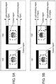
- FIG. 5A, FIG. 5B are diagrams illustrating change processing of the cutout position according to the exemplary embodiment.
- FIG. 5A, FIG. 5B are diagrams illustrating processing to be performed by image correction unit 203 by using the images in the initial state and the aging state acquired by left camera 101 and right camera 102.
- description is provided of a case where the light-shielding regions are provided only in upper and lower portions of the image for purposes of simple description.
- a method for providing the light-shielding region is arbitrary.
- the regions (number of pixels) shielded by first enclosure 104a and second enclosure 104b are identical between left camera 101 and right camera 102.
- the upper and lower light-shielding regions (number of pixels) have an identical value.
- the value is defined to be X [pix]. This X [pix] is stored in positional displacement amount calculator 201 in advance as an initial value.
- left camera 101 and right camera 102 are physically displaced in the aging state.
- These physical displacement amounts are calculated by utilizing the change in the regions (number of pixels) shielded by first enclosure 104a and second enclosure 104b.
- the region (number of pixels) shielded by second enclosure 104b the region (number of pixels) in an upper portion of the screen becomes small, X - ⁇ X [pix], whereas the region (number of pixels) in a lower portion of the screen becomes large, X + ⁇ X [pix].
- This value of the region (number of pixels) in the upper portion of the screen: X - ⁇ X [pix] and the value of the region (number of pixels) in the lower portion of the screen: X + ⁇ X [pix] are stored in positional displacement amount calculator 201.
- image correction unit 203 cuts out the image signal captured by displaced right camera 102 from a range in which the cutout position is displaced by X[pix] from the initial cutout position. Accordingly, distance measurement unit 204 receives the image of a range identical to a cutout range in the initial state, and performing image matching within the cutout range enables accurate distance measurement without any change from the initial state.
- FIG. 6 is a flowchart illustrating calibration processing of vehicle-mounted stereo camera device 100.
- a driver starts an engine of a vehicle
- image signals captured by left camera 101 and right camera 102 are input into stereo processor 200, and then calibration processing starts (S1).
- Positional displacement amount calculator 201 of stereo processor 200 calculates the physical displacement amounts of the cameras (S2).
- a certain threshold is provided in advance for the displacement amount calculated here, and stereo processor 200 determines whether at least one of the displacement amounts exceeds the threshold (S3).
- stereo processor 200 causes monitor 400 to display an error and notifies the driver that maintenance is needed (S4).
- stereo processor 200 stores the displacement amounts in correction value recorder 202 as correction values (S5).
- Image correction unit 203 then changes the cutout position by a number of pixels corresponding to each correction value in each image captured by each of left camera 101 and right camera 102 (S6).
- Distance measurement unit 204 receives the cutout right and left images to perform distance measurement.
- the calibration ends (S7). Performing this processing every time the user starts the engine of the vehicle always enables accurate distance measurement.
- the exemplary embodiment has been described as illustration of the technology to be disclosed in this application.
- the technology in the present disclosure is not limited to this exemplary embodiment, and may be applied to exemplary embodiments to which changes, replacements, additions, and omissions have been made. It is also possible to make a new exemplary embodiment by combining components described in the aforementioned exemplary embodiment.
- stereo processor 200 determines whether the displacement amounts exceed the threshold.
- the present disclosure can be applied to the vehicle-mounted stereo camera device.
Landscapes
- Engineering & Computer Science (AREA)
- Multimedia (AREA)
- Physics & Mathematics (AREA)
- General Physics & Mathematics (AREA)
- Theoretical Computer Science (AREA)
- Mechanical Engineering (AREA)
- Signal Processing (AREA)
- Computer Vision & Pattern Recognition (AREA)
- Health & Medical Sciences (AREA)
- Vascular Medicine (AREA)
- General Health & Medical Sciences (AREA)
- Chemical & Material Sciences (AREA)
- Combustion & Propulsion (AREA)
- Transportation (AREA)
- Measurement Of Optical Distance (AREA)
Abstract
Description
- The present disclosure relates to a vehicle-mounted stereo camera device.
- PTL 1 discloses a vehicle-mounted stereo camera device having a function to adjust a positional displacement. The vehicle-mounted stereo camera device described in PTL 1 adjusts the positional displacement of a stereo camera based on an image obtained by capturing a fender marker.
- PTL 1: Unexamined Japanese Patent Publication No.
2001-233139 - The present disclosure provides a vehicle-mounted stereo camera device capable of achieving high-precision distance detection.
- The vehicle-mounted stereo camera device according to the present disclosure includes: a first image capturing unit and a second image capturing unit disposed to cause a visual field of the first image capturing unit and a visual field of the second image capturing unit to overlap each other; a first enclosure that encloses the first image capturing unit and has a portion that is within the visual field of the first image capturing unit; and a second enclosure that encloses the second image capturing unit and has a portion that is within the visual field of the second image capturing unit. The vehicle-mounted stereo camera device according to the present disclosure further includes a controller that calculates a distance to a body outside the vehicle based on an image captured by the first image capturing unit, on an image captured by the second image capturing unit, and on positions of the first image capturing unit and the second image capturing unit on the vehicle.
- Also, the controller detects a displacement amount of the first image capturing unit based on an amount of change in a position of the first enclosure within the visual field of the first image capturing unit, and then the controller changes a cutout position in the image captured by the first image capturing unit based on the displacement amount of the first image capturing unit. In addition, the controller detects a displacement amount of the second image capturing unit based on an amount of change in a position of the second enclosure within the visual field of the second image capturing unit, and then the controller changes a cutout position in the image captured by the second image capturing unit based on the displacement amount of the second image capturing unit.
- The vehicle-mounted stereo camera device according to the present disclosure can achieve high-precision distance detection.
-
-
FIG. 1 is a block diagram illustrating a configuration of a vehicle-mounted stereo camera device according to the exemplary embodiment. -
FIG. 2 is a schematic view illustrating the configuration of the vehicle-mounted stereo camera device according to the exemplary embodiment. -
FIG. 3 is a schematic view illustrating the front configuration of the vehicle-mounted stereo camera device according to the exemplary embodiment. -
FIG. 4 shows a schematic view illustrating the cross-sectional configuration from side of the vehicle-mounted stereo camera device according to the exemplary embodiment. -
FIG. 5A is a diagram illustrating change processing of a cutout position according to the exemplary embodiment. -
FIG. 5B is a diagram illustrating the change processing of the cutout position according to the exemplary embodiment. -
FIG. 6 is a flowchart illustrating calibration processing according to the exemplary embodiment. - An exemplary embodiment will be described in detail below with reference to the drawings as appropriate. However, a description more detailed than necessary may be omitted. For example, a detailed description of already well-known matters and a repeated description regarding substantially identical components may be omitted. This is intended to avoid making the following description unnecessarily redundant and to make it easier for a person skilled in the art to understand the exemplary embodiment.
- It is to be noted that the accompanying drawings and the following description are provided in order for a person skilled in the art to fully understand the present disclosure, and are not intended to limit the subject described in the appended claims.
- The exemplary embodiment will be described below with reference to
FIGS. 1 to 6 . -
FIG. 1 is a block diagram illustrating a configuration of vehicle-mountedstereo camera device 100 according to the exemplary embodiment. InFIG. 1 , vehicle-mountedstereo camera device 100 includes left camera (first image capturing unit) 101, right camera (second image capturing unit) 102, stereo processor (controller) 200,image signal recorder 300,monitor 400,recording device 500, and power source I/F 600. - Image signals captured by
left camera 101 andright camera 102 are input intostereo processor 200 andimage signal recorder 300.Stereo processor 200 determines parallax from a matching level of two images by using a technique of image matching.Stereo processor 200 calculates a distance to an object to be measured that exists outside a vehicle by a principle of triangulation based on the parallax and a distance betweenleft camera 101 andright camera 102. The image signals captured byleft camera 101 andright camera 102, and distance results calculated bystereo processor 200 are displayed onmonitor 400 and are recorded inrecording device 500. Power source I/F 600 supplies electricity from a cigarette lighter socket, a battery, or the like of the vehicle to each unit. -
Stereo processor 200 includes positionaldisplacement amount calculator 201 that detects physical displacement amounts ofleft camera 101 andright camera 102,correction value recorder 202 that records the positional displacement amount,image correction unit 203 that changes cutout positions of images captured byleft camera 101 andright camera 102 based on the positional displacement amount, anddistance measurement unit 204 that calculates the parallax from the cutout right and left images and converts the parallax into the distance to the object to be measured. -
FIG. 2 is a schematic view illustrating the configuration of vehicle-mountedstereo camera device 100 according to the exemplary embodiment. InFIG. 2 ,left camera 101 andright camera 102 are mounted inside the vehicle at a distance of a base length away viaholder 103 to cause visual fields to overlap each other.Left camera 101 andright camera 102 are adjusted during manufacturing to cause optical axes to become parallel with each other. Each ofleft camera 101 andright camera 102 includes an imaging element, a zoom lens, a focus lens, a fixed lens, and other elements. -
FIG. 3 is a schematic view illustrating the front configuration of vehicle-mountedstereo camera device 100 according to the exemplary embodiment. As illustrated inFIG. 3 , vehicle-mountedstereo camera device 100 includesfirst enclosure 104a that encloses surroundings ofleft camera 101 ahead ofleft camera 101 includingleft lens 111a. In addition, vehicle-mountedstereo camera device 100 includessecond enclosure 104b that encloses surroundings ofright camera 102 ahead ofright camera 102 includingright lens 111b.First enclosure 104a includes a portion that is within the visual field ofleft camera 101. Also,second enclosure 104b includes a portion that is within the visual field ofright camera 102. It is to be noted thatfirst enclosure 104a andsecond enclosure 104b also have a function to prevent a user from touching the cameras and disabling accurate distance measurement. -
FIG. 4 shows a schematic view illustrating the cross-sectional configuration from side of the vehicle-mounted stereo camera device according to the exemplary embodiment. InFIG. 4 , (a) illustrates disposition in an initial state and (b) illustrates a state in an aging state. -
Left camera 101 andright camera 102 are mechanically adjusted to cause optical axes to become parallel with each other during an initial manufacturing stage. Nevertheless, however precisely initial adjustment may be performed, it is difficult to hold an initial value continuously. - For example, as illustrated in
FIG. 4(a) , in the initial state,right lens 111b is horizontally installed with respect tosecond enclosure 104b; however, when time elapses, as illustrated inFIG. 4(b) , due to aging,right lens 111b cannot keep horizontal with respect tosecond enclosure 104b. In particular, for on-vehicle applications, influence of temperature change, vibration, and the like inside a vehicle is large and is likely to cause positional displacements of the cameras. - Therefore, vehicle-mounted
stereo camera device 100 according to the present disclosure detects the displacement amounts of the cameras by usingfirst enclosure 104a andsecond enclosure 104b which are configured to be reflected within capturing visual fields ofleft camera 101 andright camera 102, respectively. Vehicle-mountedstereo camera device 100 then changes the cutout positions in the images based on the detected displacement amounts. This correction method enables achievement of high-precision distance measurement without errors during the distance measurement. - In
FIG. 4 , for example, specifically,second enclosure 104b is provided with a light-shielding region with a length of H so as to be reflected within the capturing visual field at a position distance D distant from a front ball ofright lens 111b.Stereo processor 200 checks whether the optical axis has changed using the amount of change in the position of the light-shielding region. Then, when the position of the light-shielding region changes, the positional displacement amount of the camera is detected based on the amount of change in the light-shielding region, enabling accurate distance measurement. - It is to be noted that since distance D and light-shielding section H are already known, how many degrees the camera has displaced in which direction can be detected easily from a video. Accordingly, even when the camera needs to be adjusted after installation for maintenance or the like, the adjustment can be performed easily.
-
FIG. 5A, FIG. 5B are diagrams illustrating change processing of the cutout position according to the exemplary embodiment. In other words,FIG. 5A, FIG. 5B are diagrams illustrating processing to be performed byimage correction unit 203 by using the images in the initial state and the aging state acquired byleft camera 101 andright camera 102. Here, description is provided of a case where the light-shielding regions are provided only in upper and lower portions of the image for purposes of simple description. A method for providing the light-shielding region is arbitrary. - As illustrated in
FIG. 5A , in the initial state, sinceleft camera 101 andright camera 102 are accurately adjusted in the manufacturing stage, the regions (number of pixels) shielded byfirst enclosure 104a andsecond enclosure 104b are identical betweenleft camera 101 andright camera 102. In addition, in bothleft camera 101 andright camera 102, the upper and lower light-shielding regions (number of pixels) have an identical value. Here, the value is defined to be X [pix]. This X [pix] is stored in positionaldisplacement amount calculator 201 in advance as an initial value. - In contrast, as illustrated in
FIG. 5B ,left camera 101 andright camera 102 are physically displaced in the aging state. These physical displacement amounts are calculated by utilizing the change in the regions (number of pixels) shielded byfirst enclosure 104a andsecond enclosure 104b. Here, consider an example in which onlyright camera 102 is displaced by ΔX [pix] in a lower direction with respect to a horizontal. In this case, of the regions (number of pixels) shielded bysecond enclosure 104b, the region (number of pixels) in an upper portion of the screen becomes small, X - ΔX [pix], whereas the region (number of pixels) in a lower portion of the screen becomes large, X + ΔX [pix]. This value of the region (number of pixels) in the upper portion of the screen: X - ΔX [pix] and the value of the region (number of pixels) in the lower portion of the screen: X + ΔX [pix] are stored in positionaldisplacement amount calculator 201. - Among the image signals which are captured by
left camera 101 andright camera 102 and recorded inimage signal recorder 300,image correction unit 203 cuts out the image signal captured by displacedright camera 102 from a range in which the cutout position is displaced by X[pix] from the initial cutout position. Accordingly,distance measurement unit 204 receives the image of a range identical to a cutout range in the initial state, and performing image matching within the cutout range enables accurate distance measurement without any change from the initial state. -
FIG. 6 is a flowchart illustrating calibration processing of vehicle-mountedstereo camera device 100. InFIG. 6 , when a driver starts an engine of a vehicle, image signals captured byleft camera 101 andright camera 102 are input intostereo processor 200, and then calibration processing starts (S1). Positionaldisplacement amount calculator 201 ofstereo processor 200 calculates the physical displacement amounts of the cameras (S2). A certain threshold is provided in advance for the displacement amount calculated here, andstereo processor 200 determines whether at least one of the displacement amounts exceeds the threshold (S3). When the at least one of the displacement amounts exceeds the threshold,stereo processor 200 causes monitor 400 to display an error and notifies the driver that maintenance is needed (S4). - On the other hand, when none of the displacement amounts exceeds the threshold,
stereo processor 200 stores the displacement amounts incorrection value recorder 202 as correction values (S5).Image correction unit 203 then changes the cutout position by a number of pixels corresponding to each correction value in each image captured by each ofleft camera 101 and right camera 102 (S6).Distance measurement unit 204 receives the cutout right and left images to perform distance measurement. Thus, the calibration ends (S7). Performing this processing every time the user starts the engine of the vehicle always enables accurate distance measurement. - As described above, the exemplary embodiment has been described as illustration of the technology to be disclosed in this application. The technology in the present disclosure, however, is not limited to this exemplary embodiment, and may be applied to exemplary embodiments to which changes, replacements, additions, and omissions have been made. It is also possible to make a new exemplary embodiment by combining components described in the aforementioned exemplary embodiment.
- In [Calibration processing] of the exemplary embodiment, every time calculating the displacement amounts in S2,
stereo processor 200 determines whether the displacement amounts exceed the threshold. However, it is also possible to record the displacement amounts multiple times and to determine whether the displacement amounts exceed the threshold by using an average of the displacement amounts or the like. It is also possible to change the cutout position based on the average of the displacement amounts recorded multiple times, or the like. - It is to be noted that since the aforementioned exemplary embodiment is intended to illustrate the technology in the present disclosure, various changes, replacements, additions, omissions, and the like may be made within the scope of the appended claims or equivalents thereof.
- The present disclosure can be applied to the vehicle-mounted stereo camera device.
-
- 100
- vehicle-mounted stereo camera device
- 101
- left camera (first image capturing unit)
- 102
- right camera (second image capturing unit)
- 103
- holder
- 104a
- first enclosure
- 104b
- second enclosure
- 111a
- left lens
- 111b
- right lens
- 200
- stereo processor (controller)
- 201
- positional displacement amount calculator
- 202
- correction value recorder
- 203
- image correction unit
- 204
- distance measurement unit
- 300
- image signal recorder
- 400
- monitor
- 500
- recording device
- 600
- power source I/F
Claims (4)
- A vehicle-mounted stereo camera device comprising:a first image capturing unit and a second image capturing unit disposed to cause a visual field of the first image capturing unit and a visual field of the second image capturing unit to overlap each other;a first enclosure that encloses the first image capturing unit and has a portion that is within the visual field of the first image capturing unit;a second enclosure that encloses the second image capturing unit and has a portion that is within the visual field of the second image capturing unit; anda controller that calculates a distance to a body outside a vehicle based on an image captured by the first image capturing unit, on an image captured by the second image capturing unit, and on positions of the first image capturing unit and the second image capturing unit on the vehicle,wherein the controller:detects a displacement amount of the first image capturing unit based on an amount of change in a position of the first enclosure within the visual field of the first image capturing unit;changes a cutout position in the image captured by the first image capturing unit based on the displacement amount of the first image capturing unit;detects a displacement amount of the second image capturing unit based on an amount of change in a position of the second enclosure within the visual field of the second image capturing unit; andchanges a cutout position in the image captured by the second image capturing unit based on the displacement amount of the second image capturing unit.
- The vehicle-mounted stereo camera device according to claim 1, wherein the controller:calculates and stores the displacement amounts every time electric power is supplied to the vehicle;calculates an average of the displacement amounts when a number of times of the electric power supply reaches a predetermined number; andchanges the cutout positions based on the average of the displacement amounts.
- A correction method of a vehicle-mounted stereo camera device comprising enclosures that enclose image capturing units and have portions that are within visual fields of the image capturing units,
the correction method comprising:detecting displacement amounts of the image capturing units based on amounts of change in positions of the enclosures within the visual fields of the image capturing units; andchanging a cutout position in an image captured by each of the image capturing units based on the displacement amounts. - The correction method of a vehicle-mounted stereo camera device according to claim 3, the correction method further comprising:calculating and storing the displacement amounts every time electric power is supplied to a vehicle;calculating an average of the displacement amounts when a number of times of the electric power supply reaches a predetermined number; andchanging the cutout positions based on the average of the displacement amounts.
Applications Claiming Priority (2)
| Application Number | Priority Date | Filing Date | Title |
|---|---|---|---|
| JP2015175287 | 2015-09-07 | ||
| PCT/JP2016/002919 WO2017042998A1 (en) | 2015-09-07 | 2016-06-17 | In-vehicle stereo camera device and method for correcting same |
Publications (2)
| Publication Number | Publication Date |
|---|---|
| EP3348962A1 true EP3348962A1 (en) | 2018-07-18 |
| EP3348962A4 EP3348962A4 (en) | 2018-08-22 |
Family
ID=58239332
Family Applications (1)
| Application Number | Title | Priority Date | Filing Date |
|---|---|---|---|
| EP16843872.9A Withdrawn EP3348962A4 (en) | 2015-09-07 | 2016-06-17 | In-vehicle stereo camera device and method for correcting same |
Country Status (4)
| Country | Link |
|---|---|
| US (1) | US10220783B2 (en) |
| EP (1) | EP3348962A4 (en) |
| JP (1) | JPWO2017042998A1 (en) |
| WO (1) | WO2017042998A1 (en) |
Cited By (1)
| Publication number | Priority date | Publication date | Assignee | Title |
|---|---|---|---|---|
| WO2021134689A1 (en) * | 2019-12-31 | 2021-07-08 | 深圳市大疆创新科技有限公司 | Distance measuring apparatus and distance measuring system |
Families Citing this family (6)
| Publication number | Priority date | Publication date | Assignee | Title |
|---|---|---|---|---|
| JP6997551B2 (en) * | 2017-07-28 | 2022-01-17 | 日立Astemo株式会社 | In-vehicle environment recognition device |
| KR20190013224A (en) * | 2017-08-01 | 2019-02-11 | 엘지전자 주식회사 | Mobile terminal |
| DE102018208136A1 (en) * | 2018-05-24 | 2019-11-28 | Conti Temic Microelectronic Gmbh | optical detection system |
| GB2601307B (en) * | 2020-11-23 | 2024-11-27 | Bioseco Sp Z O O | A Stereovision Method and System |
| EP4248170A1 (en) | 2020-11-23 | 2023-09-27 | Bioseco Sp. z o.o. | A stereovision method and system |
| US12397712B2 (en) * | 2023-01-19 | 2025-08-26 | Panasonic Automotive Systems Co., Ltd. | Vehicular camera |
Family Cites Families (8)
| Publication number | Priority date | Publication date | Assignee | Title |
|---|---|---|---|---|
| JP4393659B2 (en) | 2000-02-25 | 2010-01-06 | 富士重工業株式会社 | In-vehicle preview sensor position adjustment device |
| JP4636979B2 (en) * | 2005-09-09 | 2011-02-23 | キヤノン株式会社 | Imaging apparatus and control method thereof |
| JP4426535B2 (en) * | 2006-01-17 | 2010-03-03 | 本田技研工業株式会社 | Vehicle periphery monitoring device |
| JP4859652B2 (en) * | 2006-12-15 | 2012-01-25 | アルパイン株式会社 | Image display device |
| JP2012198075A (en) * | 2011-03-18 | 2012-10-18 | Ricoh Co Ltd | Stereoscopic camera device and image adjusting method |
| JP6221464B2 (en) * | 2013-07-26 | 2017-11-01 | 株式会社リコー | Stereo camera device, moving body control system, moving body, and program |
| DE102013017341A1 (en) * | 2013-10-18 | 2014-06-18 | Daimler Ag | Apparatus for calibration of camera assembly in vehicle, executes extrinsic calibration parameter of individual camera of camera assembly, when deviation of individual camera from desired position is detected by acceleration sensor |
| KR20160059376A (en) * | 2014-11-18 | 2016-05-26 | 엘지전자 주식회사 | Electronic appartus and method for controlling the same |
-
2016
- 2016-06-17 WO PCT/JP2016/002919 patent/WO2017042998A1/en not_active Ceased
- 2016-06-17 EP EP16843872.9A patent/EP3348962A4/en not_active Withdrawn
- 2016-06-17 JP JP2017513829A patent/JPWO2017042998A1/en active Pending
-
2017
- 2017-04-17 US US15/488,559 patent/US10220783B2/en active Active
Cited By (1)
| Publication number | Priority date | Publication date | Assignee | Title |
|---|---|---|---|---|
| WO2021134689A1 (en) * | 2019-12-31 | 2021-07-08 | 深圳市大疆创新科技有限公司 | Distance measuring apparatus and distance measuring system |
Also Published As
| Publication number | Publication date |
|---|---|
| EP3348962A4 (en) | 2018-08-22 |
| JPWO2017042998A1 (en) | 2018-06-28 |
| US10220783B2 (en) | 2019-03-05 |
| WO2017042998A1 (en) | 2017-03-16 |
| US20170217370A1 (en) | 2017-08-03 |
Similar Documents
| Publication | Publication Date | Title |
|---|---|---|
| US10220783B2 (en) | Vehicle-mounted stereo camera device and method for correcting the same | |
| KR101787304B1 (en) | Calibration method, calibration device, and computer program product | |
| EP2902967B1 (en) | Stereo camera calibration method, disparity calculating device, and stereo camera | |
| US10176594B2 (en) | Progressive in-vehicle camera calibrator, image generator, in-vehicle camera calibration method, and image generation method | |
| US8593536B2 (en) | Image pickup apparatus with calibration function | |
| JP6970577B2 (en) | Peripheral monitoring device and peripheral monitoring method | |
| JP6975003B2 (en) | Peripheral monitoring device and its calibration method | |
| JP2012189324A (en) | Stereo camera | |
| KR20140071188A (en) | Method for acquiring horizontal distance between camera and target, camera and surveillance system adopting the method | |
| WO2014050282A1 (en) | Stereo camera device | |
| US10313658B2 (en) | Vehicle-mounted stereo camera device and method for correcting the same | |
| KR20200118073A (en) | System and method for dynamic three-dimensional calibration | |
| JP2019132855A (en) | Stereo camera calibration method, parallax calculation device, and stereo camera | |
| JP2009250785A (en) | Imaging device | |
| EP4012495A1 (en) | Method for correcting stereocamera and device for correcting stereocamera | |
| JP2015025730A (en) | Stereo camera device, moving body control system, moving body, and program | |
| EP3564747A1 (en) | Imaging device and imaging method | |
| EP4235574A1 (en) | Measuring device, moving device, measuring method, and storage medium | |
| WO2016079965A1 (en) | Depth detection apparatus, imaging apparatus and depth detection method | |
| US10384608B2 (en) | Vehicle-mounted stereo camera device and method for correcting the same | |
| JP2014202661A (en) | Range finder | |
| JP6571571B2 (en) | Imaging apparatus, in-vehicle camera, and image processing method | |
| KR20150110069A (en) | Stereoscopic camera apparatus and alignment control method thereof |
Legal Events
| Date | Code | Title | Description |
|---|---|---|---|
| PUAI | Public reference made under article 153(3) epc to a published international application that has entered the european phase |
Free format text: ORIGINAL CODE: 0009012 |
|
| 17P | Request for examination filed |
Effective date: 20170324 |
|
| AK | Designated contracting states |
Kind code of ref document: A1 Designated state(s): AL AT BE BG CH CY CZ DE DK EE ES FI FR GB GR HR HU IE IS IT LI LT LU LV MC MK MT NL NO PL PT RO RS SE SI SK SM TR |
|
| AX | Request for extension of the european patent |
Extension state: BA ME |
|
| A4 | Supplementary search report drawn up and despatched |
Effective date: 20180724 |
|
| RIC1 | Information provided on ipc code assigned before grant |
Ipc: H04N 13/246 20180101ALI20180718BHEP Ipc: G01C 3/00 20060101ALI20180718BHEP Ipc: G01C 3/06 20060101AFI20180718BHEP Ipc: B60R 1/00 20060101ALI20180718BHEP Ipc: H04N 13/239 20180101ALI20180718BHEP Ipc: H04N 7/18 20060101ALI20180718BHEP |
|
| DAV | Request for validation of the european patent (deleted) | ||
| DAX | Request for extension of the european patent (deleted) | ||
| STAA | Information on the status of an ep patent application or granted ep patent |
Free format text: STATUS: THE APPLICATION IS DEEMED TO BE WITHDRAWN |
|
| 18D | Application deemed to be withdrawn |
Effective date: 20190221 |