EP3348928A1 - Air-conditioning indoor unit - Google Patents
Air-conditioning indoor unit Download PDFInfo
- Publication number
- EP3348928A1 EP3348928A1 EP16844340.6A EP16844340A EP3348928A1 EP 3348928 A1 EP3348928 A1 EP 3348928A1 EP 16844340 A EP16844340 A EP 16844340A EP 3348928 A1 EP3348928 A1 EP 3348928A1
- Authority
- EP
- European Patent Office
- Prior art keywords
- air
- front flap
- adjustment member
- direction adjustment
- flap
- Prior art date
- Legal status (The legal status is an assumption and is not a legal conclusion. Google has not performed a legal analysis and makes no representation as to the accuracy of the status listed.)
- Withdrawn
Links
- 238000004378 air conditioning Methods 0.000 title claims abstract description 78
- 238000007664 blowing Methods 0.000 claims abstract description 6
- 238000011144 upstream manufacturing Methods 0.000 claims description 12
- 230000036544 posture Effects 0.000 description 40
- 238000005192 partition Methods 0.000 description 36
- 230000004048 modification Effects 0.000 description 12
- 238000012986 modification Methods 0.000 description 12
- 230000000694 effects Effects 0.000 description 8
- 238000009833 condensation Methods 0.000 description 2
- 230000005494 condensation Effects 0.000 description 2
- 238000001816 cooling Methods 0.000 description 2
- 239000007788 liquid Substances 0.000 description 2
- 230000001143 conditioned effect Effects 0.000 description 1
- 230000014509 gene expression Effects 0.000 description 1
- 238000003756 stirring Methods 0.000 description 1
- XLYOFNOQVPJJNP-UHFFFAOYSA-N water Substances O XLYOFNOQVPJJNP-UHFFFAOYSA-N 0.000 description 1
Images




Classifications
-
- F—MECHANICAL ENGINEERING; LIGHTING; HEATING; WEAPONS; BLASTING
- F24—HEATING; RANGES; VENTILATING
- F24F—AIR-CONDITIONING; AIR-HUMIDIFICATION; VENTILATION; USE OF AIR CURRENTS FOR SCREENING
- F24F11/00—Control or safety arrangements
- F24F11/89—Arrangement or mounting of control or safety devices
-
- F—MECHANICAL ENGINEERING; LIGHTING; HEATING; WEAPONS; BLASTING
- F24—HEATING; RANGES; VENTILATING
- F24F—AIR-CONDITIONING; AIR-HUMIDIFICATION; VENTILATION; USE OF AIR CURRENTS FOR SCREENING
- F24F13/00—Details common to, or for air-conditioning, air-humidification, ventilation or use of air currents for screening
- F24F13/08—Air-flow control members, e.g. louvres, grilles, flaps or guide plates
- F24F13/10—Air-flow control members, e.g. louvres, grilles, flaps or guide plates movable, e.g. dampers
- F24F13/14—Air-flow control members, e.g. louvres, grilles, flaps or guide plates movable, e.g. dampers built up of tilting members, e.g. louvre
-
- F—MECHANICAL ENGINEERING; LIGHTING; HEATING; WEAPONS; BLASTING
- F24—HEATING; RANGES; VENTILATING
- F24F—AIR-CONDITIONING; AIR-HUMIDIFICATION; VENTILATION; USE OF AIR CURRENTS FOR SCREENING
- F24F1/00—Room units for air-conditioning, e.g. separate or self-contained units or units receiving primary air from a central station
- F24F1/0007—Indoor units, e.g. fan coil units
- F24F1/0011—Indoor units, e.g. fan coil units characterised by air outlets
-
- F—MECHANICAL ENGINEERING; LIGHTING; HEATING; WEAPONS; BLASTING
- F24—HEATING; RANGES; VENTILATING
- F24F—AIR-CONDITIONING; AIR-HUMIDIFICATION; VENTILATION; USE OF AIR CURRENTS FOR SCREENING
- F24F1/00—Room units for air-conditioning, e.g. separate or self-contained units or units receiving primary air from a central station
- F24F1/0007—Indoor units, e.g. fan coil units
- F24F1/0043—Indoor units, e.g. fan coil units characterised by mounting arrangements
- F24F1/0057—Indoor units, e.g. fan coil units characterised by mounting arrangements mounted in or on a wall
Definitions
- the present invention relates to an air conditioning indoor unit.
- An air conditioning indoor unit pertaining to a first aspect of the invention is a wall-mounted air conditioning indoor unit that is installed on a side wall of an air conditioning target space and uses plural air direction adjustment members to change the air direction of outlet air blown out from an air outlet, the air conditioning indoor unit comprising a first air direction adjustment member and a second air direction adjustment member.
- the first air direction adjustment member adjusts the air direction of the outlet air.
- the second air direction adjustment member is positioned upstream, relative to the flow of the outlet air, of the first air direction adjustment member.
- the first air direction adjustment member and the second air direction adjustment member each have airflow surfaces along which the outlet air flows.
- the first air direction adjustment member and the second air direction adjustment member adopt a predetermined posture.
- the predetermined posture is a posture in which an airflow guide surface with a projecting shape that bulges forward is formed by the two airflow surfaces.
- the first air direction adjustment member has its lower end positioned more toward the side wall than its upper end and is inclined relative to a vertical plane.
- the first air direction adjustment member has its lower end positioned more toward the side wall than its upper end and is inclined relative to a vertical plane, so the outlet air can be deflected more than 90° downward from the horizontal (more toward the side wall on which the air conditioner is installed than a vertical plane), and an "unfelt airflow" heading toward the lower portion of the side wall can be realized.
- An air conditioning indoor unit pertaining to a second aspect of the invention is the air conditioning indoor unit pertaining to the first aspect, wherein the airflow surface of the first air direction adjustment member is larger than the airflow surface of the second air direction adjustment member.
- the air that has been guided by the airflow surface of the second air direction adjustment member flows along the airflow surface of the first air direction adjustment member that is larger than the airflow surface of the second air direction adjustment member, so the airflow surface can guide the outlet air in the intended direction without allowing the outlet air to come away midway.
- An air conditioning indoor unit pertaining to a third aspect of the invention is the air conditioning indoor unit pertaining to the first aspect or the second aspect, wherein the first air direction adjustment member and the second air direction adjustment member overlap each other.
- the first air direction adjustment member and the second air direction adjustment member overlap each other, so the outlet air is prevented from bypassing a predetermined air passage space through a gap between both members.
- An air conditioning indoor unit pertaining to a fourth aspect of the invention is the air conditioning indoor unit pertaining to the third aspect, wherein a lower portion of the second air direction adjustment member overlaps the first air direction adjustment member from upstream relative to the flow of the outlet air.
- the posture becomes one in which at least the distal end of the second air direction adjustment member overlaps the back surface side (the side wall side) of the first air direction adjustment member, and the air that has been guided by the airflow surface of the second air direction adjustment member flows along the airflow surface of the first air direction adjustment member, so bypassing through a gap between both members is reliably prevented.
- An air conditioning indoor unit pertaining to a fifth aspect of the invention is the air conditioning indoor unit pertaining to the third aspect, wherein provided in either one of the first air direction adjustment member and the second air direction adjustment member at the overlapping part is a recessed portion that the other enters.
- the step between both members that arises when the lower portion of the second air direction adjustment member overlaps the first air direction adjustment member from upstream relative to the flow of the outlet air becomes smaller, so resistance when the outlet air flows over the airflow surfaces is reduced.
- An air conditioning indoor unit pertaining to a sixth aspect of the invention is the air conditioning indoor unit pertaining to the first aspect, wherein in the predetermined posture the second air direction adjustment member has its lower end positioned more forward than its upper end and is inclined 0° to 10° relative to a vertical plane and the first air direction adjustment member has its lower end positioned more toward the side wall than its upper end and is inclined 0° to 20° relative to a vertical plane.
- the airflow surface of the second air direction adjustment member and the airflow surface of the first air direction adjustment member form a large obtuse angle, so the flow of the outlet air from the airflow surface of the second air direction adjustment member to the airflow surface of the first air direction adjustment member becomes smooth.
- the first air direction adjustment member has its lower end positioned more toward the side wall than its upper end and is inclined relative to a vertical plane, so the outlet air can be deflected more than 90° downward from the horizontal (more toward the side wall on which the air conditioner is installed than a vertical plane), and an "unfelt airflow" heading toward the lower portion of the side wall can be realized.
- the air that has been guided by the airflow surface of the second air direction adjustment member flows along the airflow surface of the first air direction adjustment member that is larger than the airflow surface of the second air direction adjustment member, so the airflow surface can guide the outlet air in the intended direction without allowing the outlet air to come away midway.
- the first air direction adjustment member and the second air direction adjustment member overlap each other, so the outlet air is prevented from bypassing a predetermined air passage space through a gap between both members.
- the posture becomes one in which at least the distal end of the second air direction adjustment member overlaps the back surface side (the side wall side) of the first air direction adjustment member, and the air that has been guided by the airflow surface of the second air direction adjustment member flows along the airflow surface of the first air direction adjustment member, so bypassing through a gap between both members is reliably prevented.
- the step between both members that arises when the lower portion of the second air direction adjustment member overlaps the first air direction adjustment member from upstream relative to the flow of the outlet air becomes smaller, so resistance when the outlet air flows over the airflow surfaces is reduced.
- the airflow surface of the second air direction adjustment member and the airflow surface of the first air direction adjustment member form a large obtuse angle, so the flow of the outlet air from the airflow surface of the second air direction adjustment member to the airflow surface of the first air direction adjustment member becomes smooth.
- FIG. 1 is a perspective view of an air conditioning indoor unit 10 when in operation pertaining to the embodiment of the invention.
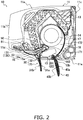
- FIG. 2 is a sectional view of the air conditioning indoor unit 10 of FIG. 1 .
- the air conditioning indoor unit 10 is a wall-mounted type. It will be noted that in both FIG. 1 and FIG. 2 the air direction mode is set to a rearward and downward airflow mode that directs outlet air toward a lower portion of a side wall on which the air conditioning indoor unit 10 is installed.
- the air conditioning indoor unit 10 has a body casing 11, an indoor heat exchanger 13, an indoor fan 14, a frame 17, and a control unit 50.
- the body casing 11 has a top surface portion 11a, a front surface panel 11b, a back surface plate 11c, a sloping lower surface portion 11d, and a horizontal lower surface portion 11e, and houses the indoor heat exchanger 13, the indoor fan 14, the frame 17, and the control unit 50 inside.
- the top surface portion 11a is positioned on the upper portion of the body casing 11, and an air inlet (not shown in the drawings) is provided in the top surface portion 11a in such a way as to extend from the front portion to the rear portion of the top surface portion 11a.
- the front surface panel 11b configures a front surface portion of the indoor unit and has a flat shape, or a curved shape with a large curvature, with no air inlet. Furthermore, the upper end of the front surface panel 11b is supported by the top surface portion 11a in such a way that the front surface panel 11b may freely rotate, so that the front surface panel 11b can be operated in a hinged manner.
- the indoor heat exchanger 13 and the indoor fan 14 are attached to the frame 17.
- the indoor heat exchanger 13 carries out heat exchange with air passing through it.
- the indoor heat exchanger 13 has an inverted V-shape in which both ends bend downward as seen in a side view, and the indoor fan 14 is positioned under the indoor heat exchanger 13.
- the indoor fan 14 is a cross-flow fan, causes air taken in from the room to be applied to and pass through the indoor heat exchanger 13, and blows out the air into the room.
- An air outlet 15 is provided in the lower portion of the body casing 11.
- a rear flap 40 that changes the direction of the outlet air blown out from the air outlet 15 is attached to the air outlet 15 in such a way that the rear flap 40 may freely rotate.
- the rear flap 40 is driven by a motor (not shown in the drawings) and not only changes the direction of the outlet air but can also open and close the air outlet 15. Furthermore, the rear flap 40 can adopt plural postures whose angles of inclination are different.
- a front flap 31 is provided in the neighborhood of the air outlet 15.
- the front flap 31 can adopt a posture in which it is inclined in the front and rear direction by a motor (not shown in the drawings), and, when operation is stopped, the front flap 31 is stowed in a stowage portion 130 provided in the sloping lower surface portion 11d between the lower end of the front surface panel 11b and the air outlet 15.
- the front flap 31 can adopt plural postures whose angles of inclination are different.
- An auxiliary front flap 32 is rotatably disposed upstream, relative to the flow of the outlet air, of the front flap 31.
- the front flap 31, the auxiliary front flap 32, and the rear flap 40 generate a rearward and downward airflow. It will be noted that the front flap 31 and the auxiliary front flap 32 will collectively be called a front flap group 30.
- the air outlet 15 is connected to the inside of the body casing 11 by an outlet air flow passage 18.
- the outlet air flow passage 18 is an air passage sandwiched between an upper scroll 171 and a lower scroll 172 of the frame 17.
- Room air is sucked by the operation of the indoor fan 14 into the indoor fan 14 via the air inlet and the indoor heat exchanger 13, travels from the indoor fan 14 through the outlet air flow passage 18, and is blown out from the air outlet 15.
- the control unit 50 is disposed in a space provided between a front drain pan 61 and an upper partition wall 161 of an air outlet forming wall 16.
- the control unit 50 carries out control of the rotational speed of the indoor fan 14 and control of the operation of the rear flap 40 and the front flap group 30.
- the front drain pan 61 is positioned under the front lower portion of the indoor heat exchanger 13 and receives dew condensation water generated by the front portion of the indoor heat exchanger 13.
- front end and rear end relating to a given member will for the sake of convenience be changed to “lower end” and “upper end,” respectively, when the member adopts a vertical posture or a posture approaching a vertical posture.
- the body casing 11 has the top surface portion 11a that gently slopes downward heading from its rear side toward its front side.
- the air inlet (not shown in the drawings) is provided in the top surface portion 11a.
- the front surface portion of the body casing 11 is configured by the front surface panel 11b.
- the front surface panel 11b extends from the front upper portion to the front lower portion of the body casing 11 while describing a gentle, circularly arcuate curved surface.
- the front side of the lower portion of the body casing 11 is configured by the sloping lower surface portion 11d, which interconnects the lower end of the front surface panel 11b and the upper end of the air outlet 15.
- a region recessed toward the inside of the body casing 11 is formed in the sloping lower surface portion 11d.
- the recessed depth of this region is set to match the thickness dimension of the front flap 31, and the region forms the stowage portion 130 in which the front flap 31 is stowed.
- the surface of the stowage portion 130 is also a gentle, circularly arcuate curved surface.
- the rear side of the lower portion of the body casing 11 is configured by the horizontal lower surface portion 11e, which extends from the rear end side of the air outlet 15 to the lower portion of the back surface.
- the air outlet 15 is formed in the lower portion of the body casing 11, and is an opening with a rectangular shape whose long sides lie along the transverse direction (the direction orthogonal to the surface of the page of FIG. 2 ).
- the outline of the air outlet 15 is formed by the air outlet forming wall 16.
- the air outlet forming wall 16 includes an upper partition wall 161, which forms an upper surface of the air outlet 15, and a lower partition wall 162, which forms a lower surface of the air outlet 15.
- a front rib 15a that projects vertically downward from the front end position of the air outlet 15 is provided on the upper partition wall 161.
- a stowage portion partition wall 131 is disposed on the opposite side of the upper partition wall 161 across the front rib 15a (in front of the front rib 15a).
- the stowage portion partition wall 131 is a wall that forms an upper surface of the stowage portion 130.
- the upper partition wall 161, the front rib 15a, and the stowage portion partition wall 131 are integrally molded.
- a rear rib 15b that projects vertically downward from the rear end position of the air outlet 15 is provided on the lower partition wall 162.
- the lower partition wall 162 and the rear rib 15b are integrally molded.
- the frame 17 is a partition wall curved so as to face the indoor fan 14.
- the frame 17 includes the upper scroll 171 and the lower scroll 172.
- the upper partition wall 161 of the air outlet forming wall 16 is adjacent in a direction tangential to the terminal end of the upper scroll 171.
- the lower partition wall 162 of the air outlet forming wall 16 is adjacent in a direction tangential to the terminal end of the lower scroll 172.
- Air traveling through the outlet air flow passage 18 proceeds along the upper scroll 171 and the lower scroll 172, is sent in a direction tangential to the terminal ends of the upper scroll 171 and the lower scroll 172, then proceeds along the upper partition wall 161 and the lower partition wall 162 of the air outlet forming wall 16, and is blown out from the air outlet 15.
- a vertical air direction adjustment plate 20 has plural blade pieces 201 disposed along the longitudinal direction of the air outlet 15 (the direction perpendicular to the surface of the page of FIG. 2 ).
- the vertical air direction adjustment plate 20 is disposed in the outlet air flow passage 18 in a position closer to the indoor fan 14 than the rear flap 40.
- the plural blade pieces 201 swing right and left about a state perpendicular to the longitudinal direction of the air outlet 15 by horizontally reciprocating along the longitudinal direction of the air outlet 15.
- FIG. 3 is an enlarged sectional view of the front flap 31 and the rear flap 40 of FIG. 2 .
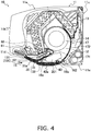
- FIG. 4 is a sectional view of the air conditioning indoor unit when operation is stopped.
- the front flap 31 is stowed in the stowage portion 130 while air conditioning operations are stopped.
- the front flap 31 moves away from the stowage portion 130 by rotating.
- a rotating shaft of the front flap 31 is set under the front rib 15a of the upper partition wall 161 of the air outlet forming wall 16, and the rear end of the front flap 31 and the rotating shaft are coupled to each other with a predetermined distance being maintained between them. Therefore, the front flap 31 rotates in such a way that as it rotates and moves away from the stowage portion 130, the height position of the rear end of the front flap 31 becomes lower.
- the front flap 31 moves away from the stowage portion 130 while both the front end and the rear end of the front flap 31 describe circular arcs. Furthermore, by rotating in the clockwise direction in-from the perspective of one looking directly at- FIG. 2 , the front flap 31 moves toward the stowage portion 130 and eventually becomes stowed in the stowage portion 130.
- the postures of the front flap 31 in an operating state include a posture in which the front flap 31 is stowed in the stowage portion 130 (see FIG. 4 ), a posture in which the front flap 31 rotates to become inclined forward and upward, a posture in which the front flap 31 rotates further to become substantially horizontal, a posture in which the front flap 31 rotates further to become inclined forward and downward, and a posture in which the front flap 31 rotates further to become inclined rearward and downward (see FIG. 2 and FIG. 3 ).
- the front flap 31 has a first surface 31a that forms an outer surface of the front flap 31 and a second surface 31b that forms an inner surface of the front flap 31 when the front flap 31 is in the posture in which it is stowed in the stowage portion 130.
- the first surface 31a and the second surface 31b form a rear surface and a front surface, respectively, of the front flap 31 when the front flap 31 adopts the posture shown in FIG. 3 in which it is inclined rearward and downward.
- the recessed portion 311 is positioned near the rotating shaft as seen from the center of the front flap 31.
- the dimension of the front flap 31 in the longitudinal direction thereof (the direction perpendicular to the surface of the page of FIG. 2 ) is set so as to be the same as or greater than the dimension of the rear flap 40 in the longitudinal direction thereof.
- the reason is that, in a case where the air direction is upward, for example, all of the outlet air whose air direction has been adjusted by the rear flap 40 is received by the front flap 31, and the action and effect thereof is to prevent the outlet air blown out from the sides of the front flap 31 from short-circuiting.
- the auxiliary front flap 32 is a plate-like member positioned upstream, relative to the flow of the outlet air, of the front flap 31.
- the auxiliary front flap 32 is smaller than the front flap 31, but the auxiliary front flap 32 is set to a size sufficient to guide the air that has traveled through the outlet air flow passage 18 to the first surface 31a of the front flap 31.
- the auxiliary front flap 32 When it is not used, the auxiliary front flap 32 is stowed in a stowage portion 16a provided in the upper partition wall 161 of the air outlet forming wall 16.
- the auxiliary front flap 32 has a first surface 32a that forms a lower surface of the auxiliary front flap 32 and a second surface 32b that forms an upper surface of the auxiliary front flap 32 when the auxiliary front flap 32 is in the posture in which it is stowed in the stowage portion 16a.
- the first surface 32a and the second surface 32b form a rear surface and a front surface, respectively, of the auxiliary front flap 32 when the auxiliary front flap 32 adopts the posture shown in FIG. 3 .
- the stowage portion 16a is formed by recessing the upper partition wall 161 of the air outlet forming wall 16 in its thickness direction.
- the depth of the stowage portion 16a is set in such a way that when the auxiliary front flap 32 is stowed in the stowage portion 16a, the first surface 32a of the auxiliary front flap 32 does not project beyond the surface of the upper partition wall 161 into the flow path.
- the auxiliary front flap 32 moves from the stowage portion 16a by rotating and projects beyond the surface of the upper partition wall 161 into the flow path.
- a rotating shaft of the auxiliary front flap 32 is set under the upstream-side end portion of the stowage portion 16a.
- the auxiliary front flap 32 rotates in such a way that its distal end enters the recessed portion 311 of the front flap 31. If at this time the entire auxiliary front flap 32 is away from the stowage portion 16a, the outlet air bypasses the air passage space sandwiched between the airflow guide surface 30a and the second surface 40bthrough a gap between the upper partition wall 161 and the auxiliary front flap 32, so to prevent this the rear end of the auxiliary front flap 32 remains in the stowage portion 16a to keep the gap between the upper partition wall 161 and the auxiliary front flap 32 from becoming larger.
- the first surface 32a of the auxiliary front flap 32 and the first surface 31a of the front flap 31 form an airflow guide surface 30a and, together with the rear flap 40, generate an airflow heading toward the lower portion of the side wall.
- the rear flap 40 has an area sufficient enough to be able to close off the air outlet 15 as shown in FIG. 4 .
- the rear flap 40 has a first surface 40a that forms an outer surface of the rear flap 40 and a second surface 40b that forms an inner surface of the rear flap 40 when the rear flap 40 adopts the posture in which it closes the air outlet 15.
- the first surface 40a and the second surface 40b form a rear surface and a front surface, respectively, of the rear flap 40 when the rear flap 40 adopts the posture shown in FIG. 3 in which it is inclined rearward and downward.
- the first surface 40a is, emphasizing design attractiveness, finished to a gentle circularly arcuate curved surface that projects outward.
- the second surface 40b includes a flat surface 40ba and a curved surface 40bb, and, as shown in FIG. 3 , the flat surface 40ba and the curved surface 40bb are disposed in this order in the second surface 40b heading from the upper end toward the lower end of the rear flap 40.
- the curved surface 40bb is a curved surface that bulges forward and has a radius equal to or greater than 200mm.
- a rotating shaft of the rear flap 40 is set in a position adjacent to the rear rib 15b of the lower partition wall 162 of the air outlet forming wall 16.
- the rear flap 40 By rotating in the counter-clockwise direction in-from the perspective of one looking directly at- FIG. 4 about the rotating shaft, the rear flap 40 operates so as to move away from the front end of the air outlet 15 and opens the air outlet 15.
- the rear flap 40 Conversely, by rotating in the clockwise direction in-from the perspective of one looking directly at- FIG. 2 about the rotating shaft, the rear flap 40 operates so as to move toward the front end of the air outlet 15 and closes the air outlet 15.
- the air conditioning indoor unit of the present embodiment adjusts the direction of the outlet air by changing the postures of the front flap 31, the auxiliary front flap 32, and the rear flap 40 according to each air direction mode as a means to control the direction of the outlet air.
- the air direction modes will be described below with reference to the drawings. It will be noted that the air direction modes can be controlled in such a way that they are changed automatically and can be selected via a remote controller or the like by the user.
- the rearward and downward airflow mode is a mode that directs the outlet air toward the lower portion of the side wall on which the air conditioning indoor unit 10 is installed.
- the outlet air travels from the lower portion of the side wall to the floor and then flows along the floor toward the opposing side wall.
- This airflow is also called an "unfelt airflow" because the airflow does not directly hit the occupant and it is difficult for the occupant to feel the flow of the air.
- the front flap 31, the auxiliary front flap 32, and the rear flap 40 adopt the postures shown in FIG. 1 to FIG. 3 .
- the auxiliary front flap 32 has its lower end positioned more forward than its upper end so that the auxiliary front flap 32 is inclined an angle ⁇ (0 to 10°) relative to a vertical plane.
- the front flap 31 has its lower end positioned more toward the side wall than its upper end so that the front flap 31 is inclined an angle ⁇ (0 to 20°) relative to a vertical plane. Because of this, the first surface 32a of the auxiliary front flap 32 and the first surface 31a of the front flap 31 form the airflow guide surface 30a with the projecting shape that bulges forward.
- the lower end of the front flap 31 at this time is positioned lower than the height position of the distal end of the "rear rib 15b that projects vertically downward from the rear end position of the air outlet 15."
- the distal end of the rear rib 15b is the lowermost end of the air outlet 15.
- the rear flap 40 has its lower end positioned more toward the side wall than its upper end so that the second surface 40b of the rear flap 40 is inclined relative to a vertical plane. Specifically, as shown in FIG. 3 , the rear flap 40 becomes inclined until the first surface 40a of the rear flap 40 contacts or is in close proximity to the distal end of the rear rib 15b.
- the gap between the rear flap 40 and the rear rib 15b is equal to or less than a certain value (5 mm), so air resistance when the air flows through the gap is increased, and the outlet air avoids the gap and flows in an air passage space sandwiched between the airflow guide surface 30a and the second surface 40b which is a wider passage.
- the outlet air travels through the air passage space sandwiched between the airflow guide surface 30a and the second surface 40b. At that time, the outlet air that has been guided by the auxiliary front flap 32 flows along the front flap 31 that is larger than the auxiliary front flap 32. Because the front flap 31 has its lower end positioned more toward the side wall than its upper end so that the front flap 31 is inclined relative to a vertical plane, the outlet air can be guided to the lower portion of the side wall that is more than 90° downward from the horizontal.
- the outlet air traveling through the air passage space sandwiched between the airflow guide surface 30a and the second surface 40b proceeds along the air passage space in a state in which forward spreading of the outlet air is blocked by the front flap 31 until the outlet air reaches lower than the height position of the distal end of the rear rib 15b (the lowermost end of the air outlet 15).
- the outlet air becomes an airflow along the second surface 40b of the rear flap 40 when the outlet air leaves the air passage space, so an airflow heading toward the lower portion of the side wall is sufficiently generated.
- the outlet air flows along, and in the order of, the flat surface 40ba and the curved surface 40bb of the second surface 40b of the rear flap 40.
- the curved surface 40bb is set to a radius equal to or greater than 200 mm so that it easily exhibits the Coanda effect, so the outlet air becomes a downward airflow along the flat surface 40ba and thereafter is drawn to the curved surface 40bb because of the Coanda effect and becomes an airflow heading toward the lower portion of the side wall.
- the front flap group 30-comprising the front flap 31 and the auxiliary front flap 32-and the rear flap 40 interact so that a rearward and downward airflow (unfelt airflow) heading toward the lower portion of the side wall is easily generated.
- a mode utilizing the auxiliary front flap 32 or a mode not utilizing the auxiliary front flap 32 is selected automatically or by the user.
- FIG. 5 is a sectional view of the air conditioning indoor unit 10 at the time of the forward and downward airflow mode utilizing the auxiliary front flap 32. Furthermore, FIG. 6 is an enlarged sectional view of the front flap 31, the auxiliary front flap 32, and the rear flap 40 in FIG. 5 .
- the front flap 31 rotates to adopt a posture in which the first surface 31a of the front flap 31 becomes inclined downward a predetermined angle x1 from the horizontal. It will be noted that in a case where it is difficult to establish a baseline for the angle because the first surface 31a is a circularly arcuate surface, a line joining both ends of the first surface 31a may also be used as a baseline for the angle as shown in FIG. 6 .
- the auxiliary front flap 32 also rotates to adopt a posture in which the first surface 32a of the auxiliary front flap 32 becomes inclined downward a predetermined angle y1 from the horizontal. If at this time the entire auxiliary front flap 32 is away from the stowage portion 16a, the outlet air bypasses the air passage space sandwiched between the airflow guide surface 30a and the second surface 40b through the gap between the upper partition wall 161 and the auxiliary front flap 32, so to prevent this the rear end of the auxiliary front flap 32 remains in the stowage portion 16a to keep the gap between the upper partition wall 161 and the auxiliary front flap 32 from becoming larger.
- the rear flap 40 also rotates to adopt a posture in which the flat surface 40ba of the second surface 40b of the rear flap 40 becomes inclined downward a predetermined angle z1 from the horizontal.
- the front end portion of the auxiliary front flap 32 overlaps the rear end portion of the front flap 31 by a dimension L upstream, relative to the flow of the outlet air, of the front flap 31 and vertically lower than the rear end surface of the front flap 31.
- the positional relationship between the front flap 31, the auxiliary front flap 32, and the gap between them becomes a relationship where the auxiliary front flap 32, the gap, and the front flap 31 are lined up in this order as seen from upstream relative to the flow of the outlet air, and the gap is hidden by the auxiliary front flap 32 that is upstream, so the air that has traveled through the outlet air flow passage 18 and has been guided by the first surface 32a of the auxiliary front flap 32 flows with the original momentum to the first surface 31a of the front flap 31 without wrapping around to the gap.
- the conditioned air is prevented from bypassing the air passage space sandwiched between the airflow guide surface 30a and the second surface 40b through that gap.
- the auxiliary front flap 32 adopts a posture in which it blocks an airflow traveling through the gap between the upper partition wall 161 and the front flap 31, and the outlet air is prevented from flowing from the upper end of the front flap 31 along both surfaces of the front flap 31, so the upper end of the front flap 31 does not create air resistance.
- an increase in the energy consumed by the indoor fan 14 and a decrease in energy saving performance are prevented.
- the forward and downward airflow mode utilizing the auxiliary front flap 32 is effective when generating forward and downward outlet air particularly in the cooling operation.
- the reason is that there is the effect of preventing dew condensation because air that has been cooled does not flow toward the second surface 31b of the first flap 31.
- the auxiliary front flap 32 is used except when generating an upward airflow in the cooling operation.
- FIG. 7 is a sectional view of the air conditioning indoor unit 10 at the time of the forward and downward airflow mode not utilizing the auxiliary front flap 32.
- the auxiliary front flap 32 is stowed in the stowage portion 16a, and the first surface 32a of the auxiliary front flap 32 lies along an extension surface of the adjacent upper partition wall 161 and does not obstruct the flow of air along the upper partition wall 161.
- the auxiliary front flap 32 In the forward and downward airflow mode not utilizing the auxiliary front flap 32, the auxiliary front flap 32 itself does not create air resistance. However, the auxiliary front flap 32 cannot block an airflow traveling through the gap between the upper partition wall 161 and the front flap 31, so it is undeniable that the upper end of the front flap 31 creates air resistance.
- a circulation airflow mode that forcefully delivers the outlet air forward and a middle airflow mode that thickly delivers the outlet air forward are selected automatically or by the user.
- FIG. 8 is a partial sectional view of the air conditioning indoor unit 10 at the time of the circulation airflow mode.
- the front flap 31 adopts a horizontal posture or a posture in which the front end of the front flap 31 is pointed horizontally forward.
- the auxiliary front flap 32 is stowed in the stowage portion 16a.
- the rear flap 40 adopts an inclined posture in which the flat surface 40ba of the second surface 40b lies along an extension of a tangent to the terminal end of the lower partition wall 162 of the air outlet forming wall 16.
- the lower partition wall 162 is also inclined so as to lie along an extension of a tangent to the terminal end of the lower scroll 172, so the lower scroll 172, the lower partition wall 162, and the flat surface 40ba become lined up as if to form one scroll wall, and the flow of air is guided on the second surface 40b of the rear flap 40 without being obstructed.
- the distance between the first surface 31a of the front flap 31 and the second surface 40b of the rear flap 40 is narrow, so the outlet air becomes restricted and increases in flow speed, is forcefully delivered forward, and stirs up the air in the air conditioning target space. As a result, stagnation of the air in the air conditioning target space can be eliminated.
- FIG. 9 is a partial sectional view of the air conditioning indoor unit 10 at the time of the middle airflow mode.
- the front flap 31 adopts a posture in which the front end of the front flap 31 is pointed upward from the horizontal.
- the auxiliary front flap 32 is stowed in the stowage portion 16a.
- the rear flap 40 adopts a posture in which the flat surface 40ba of the second surface 40b is inclined forward and downward.
- the Coanda effect is a phenomenon where, when there is a wall next to a flow of gas or liquid, the gas or liquid tends to flow in a direction along the wall surface even if the direction of the flow and the direction of the wall are different ( Ho ⁇ soku no jiten, Asakura Publishing Co., Ltd.).
- the angle formed by the front flap 31 and the rear flap 40 needs to be equal to or less than a predetermined opening angle for the first surface 31a of the front flap 31 to produce the Coanda effect.
- the positional relationship between them is disclosed in a patent document ( JP-A No. 2013-76530) filed on September 30, 2011 , by the applicant, so description will be omitted here.
- the auxiliary front flap 32 has its lower end positioned more forward than its upper end and is inclined relative to a vertical plane, and the front flap 31 has its lower end positioned more toward the side wall than its upper end and is inclined relative to a vertical plane, so the outlet air can be deflected more than 90° downward from the horizontal (more toward the side wall on which the air conditioner is installed than a vertical plane), and an "unfelt airflow" heading toward the lower portion of the side wall can be realized.
- the air that has been guided by the first surface 32a of the auxiliary front flap 32 flows along the first surface 31a of the front flap 31 that is larger than the first surface 32a of the auxiliary front flap 32, so the outlet air can be guided in the intended direction without being allowed to come away midway.
- the front flap 31 and the auxiliary front flap 32 overlap each other, so the outlet air is prevented from bypassing the air passage space sandwiched between the airflow guide surface 30a and the second surface 40b through a gap between both members.
- the posture becomes one in which at least the distal end of the auxiliary front flap 32 overlaps the back surface side (the side wall side) of the front flap 31, and the air that has been guided by the first surface 32a of the auxiliary front flap 32 flows along the first surface 31a of the front flap 31, so bypassing through a gap between both members is reliably prevented.
- the step between both members that arises when the lower portion of the auxiliary front flap 32 overlaps the front flap 31 from upstream relative to the flow of the outlet air becomes smaller, so resistance when the outlet air flows over the airflow guide surface 30a is reduced.
- the first surface 32a of the auxiliary front flap 32 and the first surface 31a of the front flap 31 form a large obtuse angle, so the flow of the outlet air from the first surface 32a of the auxiliary front flap 32 to the first surface 31a of the front flap 31 becomes smooth.
- the air conditioning indoor unit 10 has a configuration where the recessed portion 311 is provided in the first surface 31a of the front flap 31 and where the lower end part of the auxiliary front flap 32 enters the recessed portion 311.
- the air conditioning indoor unit 10 is not limited to this, and a recessed portion may also be provided in the auxiliary front flap 32.
- FIG. 10 is an enlarged sectional view of the front flap 31, the auxiliary front flap 32, and the rear flap 40 of the air conditioning indoor unit 10 pertaining to a first example modification.
- a recessed portion 321 at which the dimension of the auxiliary front flap 32 becomes smaller in the thickness direction from the second surface 32b side of the auxiliary front flap 32 is formed in the auxiliary front flap 32.
- the front flap 31 and the auxiliary front flap 32 adopt a posture in which they overlap each other, but in this case the upper end corner portion of the first surface 31a of the front flap 31 fits into the recessed portion 321 of the auxiliary front flap 32, so the step that arises between the first surface 31a of the front flap 31 and the first surface 32a of the auxiliary front flap 32 becomes smaller and airflow turbulence is reduced.
- the lower end part of the auxiliary front flap 32 overlaps the front flap 31 from the first surface 31a side.
- the air conditioning indoor unit 10 is not limited to this, and the lower end part of the auxiliary front flap 32 may also overlap the front flap 31 from the second surface 31b side.
- FIG. 11 is an enlarged sectional view of the front flap 31, the auxiliary front flap 32, and the rear flap 40 of the air conditioning indoor unit 10 pertaining to a second example modification.
- the position of the auxiliary front flap 32 is moved forward compared to the position shown in FIG. 3 and FIG. 10 . Together with this, the position and the shape of the stowage portion 16a are also changed.
- the lower end part of the auxiliary front flap 32 overlaps the front flap 31 from the second surface 31b side.
- the first surface 32a-excluding the overlapping part-of the auxiliary front flap 32 and the first surface 31a of the front flap 31 form the airflow guide surface 30a that projects forward, so just after the outlet air becomes deflected forward and downward by the first surface 32a of the auxiliary front flap 32, the outlet air becomes deflected rearward and downward by the first surface 31a of the front flap 31.
- the outlet air flows through the air passage space sandwiched between the airflow guide surface 30a and the second surface 40b of the rear flap 40 and becomes a rearward and downward airflow.
- the auxiliary front flap 32 has a configuration where it is stowed in the stowage portion 16a with the recessed shape provided in the upper partition wall 161 of the air outlet forming wall 16 and projects into the flow path by rotating.
- the auxiliary front flap 32 is not limited to this and may also have a configuration where it projects into the flow path by linearly moving.
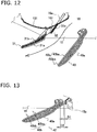
- FIG. 12 is an enlarged sectional view of the front flap 31, the auxiliary front flap 32, and the rear flap 40 of the air conditioning indoor unit 10 pertaining to a third example modification.
- the stowage portion 16a which is a space that allows the auxiliary front flap 32 to pass through it and deeply accommodates the auxiliary front flap 32, is formed in the upper partition wall 161.
- the auxiliary front flap 32 moves inside the stowage portion 16a until the front end of the auxiliary front flap 32 becomes hidden by the upper partition wall 161. Additionally, in the forward and downward airflow mode in which the auxiliary front flap 32 is used, the auxiliary front flap 32 projects into the flow path by linearly moving.
- FIG. 13 is a sectional view of the neighborhood of the rear flap 40 showing the positional relationship between the rear flap 40 and the air outlet 15.
- the upper end of the rear flap 40 forms a circular arc with a radius D2, and the center of that circular arc and the rotational center of the rear flap 40 substantially coincide with each other.
- the rear flap 40 by rotating, has its lower end (its front end when in a horizontal posture) moved rearward and downward from horizontally in front. While rotating, the circularly arcuate surface of the upper end of the rear flap 40 maintains a fixed gap D1 between itself and the rear rib 15b that projects vertically downward from the rear end position of the air outlet 15.
- the gap D1 is set equal to or less than 5 mm.
- the outlet air traveling past the upper end of the rear flap 40 flows toward the second surface 40b without traveling through the gap D1 because, even if the outlet air tries to flow through the gap D1, air resistance is too large compared to the other air passage.
- the gap D1 is set equal to or less than a certain value, so the outlet air does not travel through the gap D1 and flow toward the first surface 40a. For that reason, in the present embodiment, the first surface 40a of the rear flap 40 can be handled as part of the design of the body casing 11 without involving it in air direction control.
- Patent Document 1 JP-A No. H9-196453
Landscapes
- Engineering & Computer Science (AREA)
- Chemical & Material Sciences (AREA)
- Combustion & Propulsion (AREA)
- Mechanical Engineering (AREA)
- General Engineering & Computer Science (AREA)
- Air-Flow Control Members (AREA)
- Air Conditioning Control Device (AREA)
Abstract
Description
- The present invention relates to an air conditioning indoor unit.
- Conventionally, air conditioners that use two air direction adjustment members disposed one above the other to realize downward blowing of outlet air have become widespread. For example, in the air conditioner disclosed in patent document 1 (
JP-A No. H9-196453 - However, because a gap exists between the downward blowing up and down main flap and the up and down auxiliary flap, there is the concern that the outlet air will bypass a predetermined air passage space through the gap, resulting in appropriate airflow control not being performed, and that short-circuiting resulting from the air that has bypassed the predetermined air passage space will occur.
- It is a problem of the present invention to provide an air conditioning indoor unit that can efficiently realize downward blowing of outlet air and furthermore prevent the outlet air from bypassing the predetermined air passage space through a gap between two air direction adjustment members.
- An air conditioning indoor unit pertaining to a first aspect of the invention is a wall-mounted air conditioning indoor unit that is installed on a side wall of an air conditioning target space and uses plural air direction adjustment members to change the air direction of outlet air blown out from an air outlet, the air conditioning indoor unit comprising a first air direction adjustment member and a second air direction adjustment member. The first air direction adjustment member adjusts the air direction of the outlet air. The second air direction adjustment member is positioned upstream, relative to the flow of the outlet air, of the first air direction adjustment member. The first air direction adjustment member and the second air direction adjustment member each have airflow surfaces along which the outlet air flows. At the time of a predetermined downward blowing mode that generates an airflow heading toward a lower portion of the side wall, the first air direction adjustment member and the second air direction adjustment member adopt a predetermined posture. The predetermined posture is a posture in which an airflow guide surface with a projecting shape that bulges forward is formed by the two airflow surfaces. In the predetermined posture the first air direction adjustment member has its lower end positioned more toward the side wall than its upper end and is inclined relative to a vertical plane.
- In this air conditioning indoor unit, the first air direction adjustment member has its lower end positioned more toward the side wall than its upper end and is inclined relative to a vertical plane, so the outlet air can be deflected more than 90° downward from the horizontal (more toward the side wall on which the air conditioner is installed than a vertical plane), and an "unfelt airflow" heading toward the lower portion of the side wall can be realized.
- An air conditioning indoor unit pertaining to a second aspect of the invention is the air conditioning indoor unit pertaining to the first aspect, wherein the airflow surface of the first air direction adjustment member is larger than the airflow surface of the second air direction adjustment member.
- In this air conditioning indoor unit, the air that has been guided by the airflow surface of the second air direction adjustment member flows along the airflow surface of the first air direction adjustment member that is larger than the airflow surface of the second air direction adjustment member, so the airflow surface can guide the outlet air in the intended direction without allowing the outlet air to come away midway.
- An air conditioning indoor unit pertaining to a third aspect of the invention is the air conditioning indoor unit pertaining to the first aspect or the second aspect, wherein the first air direction adjustment member and the second air direction adjustment member overlap each other.
- In this air conditioning indoor unit, the first air direction adjustment member and the second air direction adjustment member overlap each other, so the outlet air is prevented from bypassing a predetermined air passage space through a gap between both members.
- An air conditioning indoor unit pertaining to a fourth aspect of the invention is the air conditioning indoor unit pertaining to the third aspect, wherein a lower portion of the second air direction adjustment member overlaps the first air direction adjustment member from upstream relative to the flow of the outlet air.
- In this air conditioning indoor unit, the posture becomes one in which at least the distal end of the second air direction adjustment member overlaps the back surface side (the side wall side) of the first air direction adjustment member, and the air that has been guided by the airflow surface of the second air direction adjustment member flows along the airflow surface of the first air direction adjustment member, so bypassing through a gap between both members is reliably prevented.
- An air conditioning indoor unit pertaining to a fifth aspect of the invention is the air conditioning indoor unit pertaining to the third aspect, wherein provided in either one of the first air direction adjustment member and the second air direction adjustment member at the overlapping part is a recessed portion that the other enters.
- In this air conditioning indoor unit, the step between both members that arises when the lower portion of the second air direction adjustment member overlaps the first air direction adjustment member from upstream relative to the flow of the outlet air becomes smaller, so resistance when the outlet air flows over the airflow surfaces is reduced.
- An air conditioning indoor unit pertaining to a sixth aspect of the invention is the air conditioning indoor unit pertaining to the first aspect, wherein in the predetermined posture the second air direction adjustment member has its lower end positioned more forward than its upper end and is inclined 0° to 10° relative to a vertical plane and the first air direction adjustment member has its lower end positioned more toward the side wall than its upper end and is inclined 0° to 20° relative to a vertical plane.
- In this air conditioning indoor unit, the airflow surface of the second air direction adjustment member and the airflow surface of the first air direction adjustment member form a large obtuse angle, so the flow of the outlet air from the airflow surface of the second air direction adjustment member to the airflow surface of the first air direction adjustment member becomes smooth.
- In the air conditioning indoor unit pertaining to the first aspect of the invention, the first air direction adjustment member has its lower end positioned more toward the side wall than its upper end and is inclined relative to a vertical plane, so the outlet air can be deflected more than 90° downward from the horizontal (more toward the side wall on which the air conditioner is installed than a vertical plane), and an "unfelt airflow" heading toward the lower portion of the side wall can be realized.
- In the air conditioning indoor unit pertaining to the second aspect of the invention, the air that has been guided by the airflow surface of the second air direction adjustment member flows along the airflow surface of the first air direction adjustment member that is larger than the airflow surface of the second air direction adjustment member, so the airflow surface can guide the outlet air in the intended direction without allowing the outlet air to come away midway.
- In the air conditioning indoor unit pertaining to the third aspect of the invention, the first air direction adjustment member and the second air direction adjustment member overlap each other, so the outlet air is prevented from bypassing a predetermined air passage space through a gap between both members.
- In the air conditioning indoor unit pertaining to the fourth aspect of the invention, the posture becomes one in which at least the distal end of the second air direction adjustment member overlaps the back surface side (the side wall side) of the first air direction adjustment member, and the air that has been guided by the airflow surface of the second air direction adjustment member flows along the airflow surface of the first air direction adjustment member, so bypassing through a gap between both members is reliably prevented.
- In the air conditioning indoor unit pertaining to the fifth aspect of the invention, the step between both members that arises when the lower portion of the second air direction adjustment member overlaps the first air direction adjustment member from upstream relative to the flow of the outlet air becomes smaller, so resistance when the outlet air flows over the airflow surfaces is reduced.
- In the air conditioning indoor unit pertaining to the sixth aspect of the invention, the airflow surface of the second air direction adjustment member and the airflow surface of the first air direction adjustment member form a large obtuse angle, so the flow of the outlet air from the airflow surface of the second air direction adjustment member to the airflow surface of the first air direction adjustment member becomes smooth.
-
-
FIG. 1 is a perspective view of an air conditioning indoor unit when in operation pertaining to an embodiment of the invention. -
FIG. 2 is a sectional view of the air conditioning indoor unit ofFIG. 1 . -
FIG. 3 is an enlarged sectional view of a front flap and a rear flap ofFIG. 2 . -
FIG. 4 is a sectional view of the air conditioning indoor unit when operation is stopped. -
FIG. 5 is a sectional view of the air conditioning indoor unit at the time of a forward and downward airflow mode utilizing an auxiliary front flap. -
FIG. 6 is an enlarged sectional view of the front flap, the auxiliary front flap, and the rear flap ofFIG. 5 . -
FIG. 7 is a partial sectional view of the air conditioning indoor unit at the time of the forward and downward airflow mode not utilizing the auxiliary front flap. -
FIG. 8 is a partial sectional view of the air conditioning indoor unit at the time of a circulation airflow mode. -
FIG. 9 is a partial sectional view of the air conditioning indoor unit at the time of a middle airflow mode. -
FIG. 10 is an enlarged sectional view of the front flap, the auxiliary front flap, and the rear flap of the air conditioning indoor unit pertaining to a first example modification. -
FIG. 11 is an enlarged sectional view of the front flap, the auxiliary front flap, and the rear flap of the air conditioning indoor unit pertaining to a second example modification. -
FIG. 12 is an enlarged sectional view of the front flap, the auxiliary front flap, and the rear flap of the air conditioning indoor unit pertaining to a third example modification. -
FIG. 13 is a sectional view of the neighborhood of the rear flap showing the positional relationship between the rear flap and an air outlet. - An embodiment of the invention will be described below with reference to the drawings. It will be noted that the following embodiment is a specific example of the invention and is not intended to limit the technical scope of the invention.
-
FIG. 1 is a perspective view of an air conditioningindoor unit 10 when in operation pertaining to the embodiment of the invention. Furthermore,FIG. 2 is a sectional view of the air conditioningindoor unit 10 ofFIG. 1 . InFIG. 1 andFIG. 2 , the air conditioningindoor unit 10 is a wall-mounted type. It will be noted that in bothFIG. 1 andFIG. 2 the air direction mode is set to a rearward and downward airflow mode that directs outlet air toward a lower portion of a side wall on which the air conditioningindoor unit 10 is installed. - The air conditioning
indoor unit 10 has abody casing 11, anindoor heat exchanger 13, anindoor fan 14, aframe 17, and acontrol unit 50. - The
body casing 11 has atop surface portion 11a, afront surface panel 11b, aback surface plate 11c, a slopinglower surface portion 11d, and a horizontallower surface portion 11e, and houses theindoor heat exchanger 13, theindoor fan 14, theframe 17, and thecontrol unit 50 inside. - The
top surface portion 11a is positioned on the upper portion of thebody casing 11, and an air inlet (not shown in the drawings) is provided in thetop surface portion 11a in such a way as to extend from the front portion to the rear portion of thetop surface portion 11a. - The
front surface panel 11b configures a front surface portion of the indoor unit and has a flat shape, or a curved shape with a large curvature, with no air inlet. Furthermore, the upper end of thefront surface panel 11b is supported by thetop surface portion 11a in such a way that thefront surface panel 11b may freely rotate, so that thefront surface panel 11b can be operated in a hinged manner. - The
indoor heat exchanger 13 and theindoor fan 14 are attached to theframe 17. Theindoor heat exchanger 13 carries out heat exchange with air passing through it. Furthermore, theindoor heat exchanger 13 has an inverted V-shape in which both ends bend downward as seen in a side view, and theindoor fan 14 is positioned under theindoor heat exchanger 13. Theindoor fan 14 is a cross-flow fan, causes air taken in from the room to be applied to and pass through theindoor heat exchanger 13, and blows out the air into the room. - An
air outlet 15 is provided in the lower portion of thebody casing 11. Arear flap 40 that changes the direction of the outlet air blown out from theair outlet 15 is attached to theair outlet 15 in such a way that therear flap 40 may freely rotate. Therear flap 40 is driven by a motor (not shown in the drawings) and not only changes the direction of the outlet air but can also open and close theair outlet 15. Furthermore, therear flap 40 can adopt plural postures whose angles of inclination are different. - Furthermore, a
front flap 31 is provided in the neighborhood of theair outlet 15. Thefront flap 31 can adopt a posture in which it is inclined in the front and rear direction by a motor (not shown in the drawings), and, when operation is stopped, thefront flap 31 is stowed in astowage portion 130 provided in the slopinglower surface portion 11d between the lower end of thefront surface panel 11b and theair outlet 15. Thefront flap 31 can adopt plural postures whose angles of inclination are different. - An auxiliary
front flap 32 is rotatably disposed upstream, relative to the flow of the outlet air, of thefront flap 31. In the present embodiment, thefront flap 31, the auxiliaryfront flap 32, and therear flap 40 generate a rearward and downward airflow. It will be noted that thefront flap 31 and the auxiliaryfront flap 32 will collectively be called afront flap group 30. - Furthermore, the
air outlet 15 is connected to the inside of thebody casing 11 by an outletair flow passage 18. The outletair flow passage 18 is an air passage sandwiched between anupper scroll 171 and alower scroll 172 of theframe 17. - Room air is sucked by the operation of the
indoor fan 14 into theindoor fan 14 via the air inlet and theindoor heat exchanger 13, travels from theindoor fan 14 through the outletair flow passage 18, and is blown out from theair outlet 15. - The
control unit 50 is disposed in a space provided between afront drain pan 61 and anupper partition wall 161 of an airoutlet forming wall 16. Thecontrol unit 50 carries out control of the rotational speed of theindoor fan 14 and control of the operation of therear flap 40 and thefront flap group 30. - The
front drain pan 61 is positioned under the front lower portion of theindoor heat exchanger 13 and receives dew condensation water generated by the front portion of theindoor heat exchanger 13. - In the following description, the expressions "front end" and "rear end" relating to a given member will for the sake of convenience be changed to "lower end" and "upper end," respectively, when the member adopts a vertical posture or a posture approaching a vertical posture.
- As shown in
FIG. 1 , thebody casing 11 has thetop surface portion 11a that gently slopes downward heading from its rear side toward its front side. The air inlet (not shown in the drawings) is provided in thetop surface portion 11a. - The front surface portion of the
body casing 11 is configured by thefront surface panel 11b. Thefront surface panel 11b extends from the front upper portion to the front lower portion of thebody casing 11 while describing a gentle, circularly arcuate curved surface. - The front side of the lower portion of the
body casing 11 is configured by the slopinglower surface portion 11d, which interconnects the lower end of thefront surface panel 11b and the upper end of theair outlet 15. A region recessed toward the inside of thebody casing 11 is formed in the slopinglower surface portion 11d. The recessed depth of this region is set to match the thickness dimension of thefront flap 31, and the region forms thestowage portion 130 in which thefront flap 31 is stowed. The surface of thestowage portion 130 is also a gentle, circularly arcuate curved surface. - The rear side of the lower portion of the
body casing 11 is configured by the horizontallower surface portion 11e, which extends from the rear end side of theair outlet 15 to the lower portion of the back surface. - As shown in
FIG. 2 , theair outlet 15 is formed in the lower portion of thebody casing 11, and is an opening with a rectangular shape whose long sides lie along the transverse direction (the direction orthogonal to the surface of the page ofFIG. 2 ). The outline of theair outlet 15 is formed by the airoutlet forming wall 16. - The air
outlet forming wall 16 includes anupper partition wall 161, which forms an upper surface of theair outlet 15, and alower partition wall 162, which forms a lower surface of theair outlet 15. Afront rib 15a that projects vertically downward from the front end position of theair outlet 15 is provided on theupper partition wall 161. - A stowage
portion partition wall 131 is disposed on the opposite side of theupper partition wall 161 across thefront rib 15a (in front of thefront rib 15a). The stowageportion partition wall 131 is a wall that forms an upper surface of thestowage portion 130. Theupper partition wall 161, thefront rib 15a, and the stowageportion partition wall 131 are integrally molded. - Furthermore, a
rear rib 15b that projects vertically downward from the rear end position of theair outlet 15 is provided on thelower partition wall 162. Thelower partition wall 162 and therear rib 15b are integrally molded. - The
frame 17 is a partition wall curved so as to face theindoor fan 14. Theframe 17 includes theupper scroll 171 and thelower scroll 172. Theupper partition wall 161 of the airoutlet forming wall 16 is adjacent in a direction tangential to the terminal end of theupper scroll 171. Furthermore, thelower partition wall 162 of the airoutlet forming wall 16 is adjacent in a direction tangential to the terminal end of thelower scroll 172. - Air traveling through the outlet
air flow passage 18 proceeds along theupper scroll 171 and thelower scroll 172, is sent in a direction tangential to the terminal ends of theupper scroll 171 and thelower scroll 172, then proceeds along theupper partition wall 161 and thelower partition wall 162 of the airoutlet forming wall 16, and is blown out from theair outlet 15. - A vertical air
direction adjustment plate 20 hasplural blade pieces 201 disposed along the longitudinal direction of the air outlet 15 (the direction perpendicular to the surface of the page ofFIG. 2 ). The vertical airdirection adjustment plate 20 is disposed in the outletair flow passage 18 in a position closer to theindoor fan 14 than therear flap 40. Theplural blade pieces 201 swing right and left about a state perpendicular to the longitudinal direction of theair outlet 15 by horizontally reciprocating along the longitudinal direction of theair outlet 15. -
FIG. 3 is an enlarged sectional view of thefront flap 31 and therear flap 40 ofFIG. 2 . Furthermore,FIG. 4 is a sectional view of the air conditioning indoor unit when operation is stopped. InFIG. 3 andFIG. 4 , thefront flap 31 is stowed in thestowage portion 130 while air conditioning operations are stopped. - The
front flap 31 moves away from thestowage portion 130 by rotating. A rotating shaft of thefront flap 31 is set under thefront rib 15a of theupper partition wall 161 of the airoutlet forming wall 16, and the rear end of thefront flap 31 and the rotating shaft are coupled to each other with a predetermined distance being maintained between them. Therefore, thefront flap 31 rotates in such a way that as it rotates and moves away from thestowage portion 130, the height position of the rear end of thefront flap 31 becomes lower. - By rotating in the counter-clockwise direction in-from the perspective of one looking directly at-
FIG. 4 , thefront flap 31 moves away from thestowage portion 130 while both the front end and the rear end of thefront flap 31 describe circular arcs. Furthermore, by rotating in the clockwise direction in-from the perspective of one looking directly at-FIG. 2 , thefront flap 31 moves toward thestowage portion 130 and eventually becomes stowed in thestowage portion 130. - The postures of the
front flap 31 in an operating state include a posture in which thefront flap 31 is stowed in the stowage portion 130 (seeFIG. 4 ), a posture in which thefront flap 31 rotates to become inclined forward and upward, a posture in which thefront flap 31 rotates further to become substantially horizontal, a posture in which thefront flap 31 rotates further to become inclined forward and downward, and a posture in which thefront flap 31 rotates further to become inclined rearward and downward (seeFIG. 2 andFIG. 3 ). - The
front flap 31 has afirst surface 31a that forms an outer surface of thefront flap 31 and asecond surface 31b that forms an inner surface of thefront flap 31 when thefront flap 31 is in the posture in which it is stowed in thestowage portion 130. Thefirst surface 31a and thesecond surface 31b form a rear surface and a front surface, respectively, of thefront flap 31 when thefront flap 31 adopts the posture shown inFIG. 3 in which it is inclined rearward and downward. - A recessed
portion 311, at which the dimension of thefront flap 31 becomes smaller in the thickness direction thereof as shown inFIG. 3 , is provided in thefirst surface 31a. The recessedportion 311 is positioned near the rotating shaft as seen from the center of thefront flap 31. - Furthermore, the dimension of the
front flap 31 in the longitudinal direction thereof (the direction perpendicular to the surface of the page ofFIG. 2 ) is set so as to be the same as or greater than the dimension of therear flap 40 in the longitudinal direction thereof. The reason is that, in a case where the air direction is upward, for example, all of the outlet air whose air direction has been adjusted by therear flap 40 is received by thefront flap 31, and the action and effect thereof is to prevent the outlet air blown out from the sides of thefront flap 31 from short-circuiting. - The auxiliary
front flap 32 is a plate-like member positioned upstream, relative to the flow of the outlet air, of thefront flap 31. The auxiliaryfront flap 32 is smaller than thefront flap 31, but the auxiliaryfront flap 32 is set to a size sufficient to guide the air that has traveled through the outletair flow passage 18 to thefirst surface 31a of thefront flap 31. - When it is not used, the auxiliary
front flap 32 is stowed in astowage portion 16a provided in theupper partition wall 161 of the airoutlet forming wall 16. The auxiliaryfront flap 32 has afirst surface 32a that forms a lower surface of the auxiliaryfront flap 32 and asecond surface 32b that forms an upper surface of the auxiliaryfront flap 32 when the auxiliaryfront flap 32 is in the posture in which it is stowed in thestowage portion 16a. Thefirst surface 32a and thesecond surface 32b form a rear surface and a front surface, respectively, of the auxiliaryfront flap 32 when the auxiliaryfront flap 32 adopts the posture shown inFIG. 3 . - The
stowage portion 16a is formed by recessing theupper partition wall 161 of the airoutlet forming wall 16 in its thickness direction. The depth of thestowage portion 16a is set in such a way that when the auxiliaryfront flap 32 is stowed in thestowage portion 16a, thefirst surface 32a of the auxiliaryfront flap 32 does not project beyond the surface of theupper partition wall 161 into the flow path. - Furthermore, when it is used, the auxiliary
front flap 32 moves from thestowage portion 16a by rotating and projects beyond the surface of theupper partition wall 161 into the flow path. A rotating shaft of the auxiliaryfront flap 32 is set under the upstream-side end portion of thestowage portion 16a. - When, for example, the
front flap 31 adopts a posture in which it is inclined rearward and downward as shown inFIG. 3 , the auxiliaryfront flap 32 rotates in such a way that its distal end enters the recessedportion 311 of thefront flap 31. If at this time the entire auxiliaryfront flap 32 is away from thestowage portion 16a, the outlet air bypasses the air passage space sandwiched between theairflow guide surface 30a and the second surface 40bthrough a gap between theupper partition wall 161 and the auxiliaryfront flap 32, so to prevent this the rear end of the auxiliaryfront flap 32 remains in thestowage portion 16a to keep the gap between theupper partition wall 161 and the auxiliaryfront flap 32 from becoming larger. - After this, the
first surface 32a of the auxiliaryfront flap 32 and thefirst surface 31a of thefront flap 31 form anairflow guide surface 30a and, together with therear flap 40, generate an airflow heading toward the lower portion of the side wall. - The
rear flap 40 has an area sufficient enough to be able to close off theair outlet 15 as shown inFIG. 4 . Therear flap 40 has afirst surface 40a that forms an outer surface of therear flap 40 and asecond surface 40b that forms an inner surface of therear flap 40 when therear flap 40 adopts the posture in which it closes theair outlet 15. Thefirst surface 40a and thesecond surface 40b form a rear surface and a front surface, respectively, of therear flap 40 when therear flap 40 adopts the posture shown inFIG. 3 in which it is inclined rearward and downward. - The
first surface 40a is, emphasizing design attractiveness, finished to a gentle circularly arcuate curved surface that projects outward. In contrast, thesecond surface 40b includes a flat surface 40ba and a curved surface 40bb, and, as shown inFIG. 3 , the flat surface 40ba and the curved surface 40bb are disposed in this order in thesecond surface 40b heading from the upper end toward the lower end of therear flap 40. Furthermore, inFIG. 3 , the curved surface 40bb is a curved surface that bulges forward and has a radius equal to or greater than 200mm. - A rotating shaft of the
rear flap 40 is set in a position adjacent to therear rib 15b of thelower partition wall 162 of the airoutlet forming wall 16. By rotating in the counter-clockwise direction in-from the perspective of one looking directly at-FIG. 4 about the rotating shaft, therear flap 40 operates so as to move away from the front end of theair outlet 15 and opens theair outlet 15. Conversely, by rotating in the clockwise direction in-from the perspective of one looking directly at-FIG. 2 about the rotating shaft, therear flap 40 operates so as to move toward the front end of theair outlet 15 and closes theair outlet 15. - In a state in which the
rear flap 40 has opened theair outlet 15, the outlet air that has been blown out from theair outlet 15 flows generally along thesecond surface 40b of therear flap 40. - The air conditioning indoor unit of the present embodiment adjusts the direction of the outlet air by changing the postures of the
front flap 31, the auxiliaryfront flap 32, and therear flap 40 according to each air direction mode as a means to control the direction of the outlet air. The air direction modes will be described below with reference to the drawings. It will be noted that the air direction modes can be controlled in such a way that they are changed automatically and can be selected via a remote controller or the like by the user. - The rearward and downward airflow mode is a mode that directs the outlet air toward the lower portion of the side wall on which the air conditioning
indoor unit 10 is installed. In the rearward and downward airflow mode, the outlet air travels from the lower portion of the side wall to the floor and then flows along the floor toward the opposing side wall. This airflow is also called an "unfelt airflow" because the airflow does not directly hit the occupant and it is difficult for the occupant to feel the flow of the air. - In the rearward and downward airflow mode, the
front flap 31, the auxiliaryfront flap 32, and therear flap 40 adopt the postures shown inFIG. 1 to FIG. 3 . In terms ofFIG. 3 , the auxiliaryfront flap 32 has its lower end positioned more forward than its upper end so that the auxiliaryfront flap 32 is inclined an angle α (0 to 10°) relative to a vertical plane. - Furthermore, the
front flap 31 has its lower end positioned more toward the side wall than its upper end so that thefront flap 31 is inclined an angle β (0 to 20°) relative to a vertical plane. Because of this, thefirst surface 32a of the auxiliaryfront flap 32 and thefirst surface 31a of thefront flap 31 form theairflow guide surface 30a with the projecting shape that bulges forward. - The lower end of the
front flap 31 at this time is positioned lower than the height position of the distal end of the "rear rib 15b that projects vertically downward from the rear end position of theair outlet 15." The distal end of therear rib 15b is the lowermost end of theair outlet 15. - Meanwhile, the
rear flap 40 has its lower end positioned more toward the side wall than its upper end so that thesecond surface 40b of therear flap 40 is inclined relative to a vertical plane. Specifically, as shown inFIG. 3 , therear flap 40 becomes inclined until thefirst surface 40a of therear flap 40 contacts or is in close proximity to the distal end of therear rib 15b. - In the present embodiment, the gap between the
rear flap 40 and therear rib 15b is equal to or less than a certain value (5 mm), so air resistance when the air flows through the gap is increased, and the outlet air avoids the gap and flows in an air passage space sandwiched between theairflow guide surface 30a and thesecond surface 40b which is a wider passage. - Consequently, the outlet air travels through the air passage space sandwiched between the
airflow guide surface 30a and thesecond surface 40b. At that time, the outlet air that has been guided by the auxiliaryfront flap 32 flows along thefront flap 31 that is larger than the auxiliaryfront flap 32. Because thefront flap 31 has its lower end positioned more toward the side wall than its upper end so that thefront flap 31 is inclined relative to a vertical plane, the outlet air can be guided to the lower portion of the side wall that is more than 90° downward from the horizontal. - Furthermore, the outlet air traveling through the air passage space sandwiched between the
airflow guide surface 30a and thesecond surface 40b proceeds along the air passage space in a state in which forward spreading of the outlet air is blocked by thefront flap 31 until the outlet air reaches lower than the height position of the distal end of therear rib 15b (the lowermost end of the air outlet 15). The outlet air becomes an airflow along thesecond surface 40b of therear flap 40 when the outlet air leaves the air passage space, so an airflow heading toward the lower portion of the side wall is sufficiently generated. - Moreover, the outlet air flows along, and in the order of, the flat surface 40ba and the curved surface 40bb of the
second surface 40b of therear flap 40. The curved surface 40bb is set to a radius equal to or greater than 200 mm so that it easily exhibits the Coanda effect, so the outlet air becomes a downward airflow along the flat surface 40ba and thereafter is drawn to the curved surface 40bb because of the Coanda effect and becomes an airflow heading toward the lower portion of the side wall. - As described above, the front flap group 30-comprising the
front flap 31 and the auxiliary front flap 32-and therear flap 40 interact so that a rearward and downward airflow (unfelt airflow) heading toward the lower portion of the side wall is easily generated. - In the forward and downward airflow mode, a mode utilizing the auxiliary
front flap 32 or a mode not utilizing the auxiliaryfront flap 32 is selected automatically or by the user. -
FIG. 5 is a sectional view of the air conditioningindoor unit 10 at the time of the forward and downward airflow mode utilizing the auxiliaryfront flap 32. Furthermore,FIG. 6 is an enlarged sectional view of thefront flap 31, the auxiliaryfront flap 32, and therear flap 40 inFIG. 5 . - In
FIG. 5 andFIG. 6 , first, thefront flap 31 rotates to adopt a posture in which thefirst surface 31a of thefront flap 31 becomes inclined downward a predetermined angle x1 from the horizontal. It will be noted that in a case where it is difficult to establish a baseline for the angle because thefirst surface 31a is a circularly arcuate surface, a line joining both ends of thefirst surface 31a may also be used as a baseline for the angle as shown inFIG. 6 . - Furthermore, the auxiliary
front flap 32 also rotates to adopt a posture in which thefirst surface 32a of the auxiliaryfront flap 32 becomes inclined downward a predetermined angle y1 from the horizontal. If at this time the entire auxiliaryfront flap 32 is away from thestowage portion 16a, the outlet air bypasses the air passage space sandwiched between theairflow guide surface 30a and thesecond surface 40b through the gap between theupper partition wall 161 and the auxiliaryfront flap 32, so to prevent this the rear end of the auxiliaryfront flap 32 remains in thestowage portion 16a to keep the gap between theupper partition wall 161 and the auxiliaryfront flap 32 from becoming larger. - Moreover, the
rear flap 40 also rotates to adopt a posture in which the flat surface 40ba of thesecond surface 40b of therear flap 40 becomes inclined downward a predetermined angle z1 from the horizontal. - As shown in
FIG. 6 , when thefront flap 31 and the auxiliaryfront flap 32 are viewed from the front in the horizontal direction, the front end portion of the auxiliaryfront flap 32 overlaps the rear end portion of thefront flap 31 by a dimension L upstream, relative to the flow of the outlet air, of thefront flap 31 and vertically lower than the rear end surface of thefront flap 31. - The positional relationship between the
front flap 31, the auxiliaryfront flap 32, and the gap between them becomes a relationship where the auxiliaryfront flap 32, the gap, and thefront flap 31 are lined up in this order as seen from upstream relative to the flow of the outlet air, and the gap is hidden by the auxiliaryfront flap 32 that is upstream, so the air that has traveled through the outletair flow passage 18 and has been guided by thefirst surface 32a of the auxiliaryfront flap 32 flows with the original momentum to thefirst surface 31a of thefront flap 31 without wrapping around to the gap. As a result, even if there is the gap, the conditioned air is prevented from bypassing the air passage space sandwiched between theairflow guide surface 30a and thesecond surface 40b through that gap. - As described above, in the forward and downward airflow mode utilizing the auxiliary
front flap 32, the auxiliaryfront flap 32 adopts a posture in which it blocks an airflow traveling through the gap between theupper partition wall 161 and thefront flap 31, and the outlet air is prevented from flowing from the upper end of thefront flap 31 along both surfaces of thefront flap 31, so the upper end of thefront flap 31 does not create air resistance. As a result, an increase in the energy consumed by theindoor fan 14 and a decrease in energy saving performance are prevented. - Furthermore, the forward and downward airflow mode utilizing the auxiliary
front flap 32 is effective when generating forward and downward outlet air particularly in the cooling operation. The reason is that there is the effect of preventing dew condensation because air that has been cooled does not flow toward thesecond surface 31b of thefirst flap 31. - In the present embodiment, the auxiliary
front flap 32 is used except when generating an upward airflow in the cooling operation. -
FIG. 7 is a sectional view of the air conditioningindoor unit 10 at the time of the forward and downward airflow mode not utilizing the auxiliaryfront flap 32. InFIG. 7 , the auxiliaryfront flap 32 is stowed in thestowage portion 16a, and thefirst surface 32a of the auxiliaryfront flap 32 lies along an extension surface of the adjacentupper partition wall 161 and does not obstruct the flow of air along theupper partition wall 161. - In the forward and downward airflow mode not utilizing the auxiliary
front flap 32, the auxiliaryfront flap 32 itself does not create air resistance. However, the auxiliaryfront flap 32 cannot block an airflow traveling through the gap between theupper partition wall 161 and thefront flap 31, so it is undeniable that the upper end of thefront flap 31 creates air resistance. - In the forward airflow mode, a circulation airflow mode that forcefully delivers the outlet air forward and a middle airflow mode that thickly delivers the outlet air forward are selected automatically or by the user.
-
FIG. 8 is a partial sectional view of the air conditioningindoor unit 10 at the time of the circulation airflow mode. InFIG. 8 , thefront flap 31 adopts a horizontal posture or a posture in which the front end of thefront flap 31 is pointed horizontally forward. The auxiliaryfront flap 32 is stowed in thestowage portion 16a. Therear flap 40 adopts an inclined posture in which the flat surface 40ba of thesecond surface 40b lies along an extension of a tangent to the terminal end of thelower partition wall 162 of the airoutlet forming wall 16. Thelower partition wall 162 is also inclined so as to lie along an extension of a tangent to the terminal end of thelower scroll 172, so thelower scroll 172, thelower partition wall 162, and the flat surface 40ba become lined up as if to form one scroll wall, and the flow of air is guided on thesecond surface 40b of therear flap 40 without being obstructed. - In the circulation airflow mode, the distance between the
first surface 31a of thefront flap 31 and thesecond surface 40b of therear flap 40 is narrow, so the outlet air becomes restricted and increases in flow speed, is forcefully delivered forward, and stirs up the air in the air conditioning target space. As a result, stagnation of the air in the air conditioning target space can be eliminated. -
FIG. 9 is a partial sectional view of the air conditioningindoor unit 10 at the time of the middle airflow mode. InFIG. 9 , thefront flap 31 adopts a posture in which the front end of thefront flap 31 is pointed upward from the horizontal. The auxiliaryfront flap 32 is stowed in thestowage portion 16a. Therear flap 40 adopts a posture in which the flat surface 40ba of thesecond surface 40b is inclined forward and downward. - At first glance it might seem that the outlet air would flow forward and downward along the flat surface 40ba of the
rear flap 40, but because of the Coanda effect the outlet air that has exited theair outlet 15 is drawn to thefirst surface 31a of thefront flap 31, becomes an airflow that is horizontal and a little more upward than horizontal, and is delivered. - Here, the Coanda effect is a phenomenon where, when there is a wall next to a flow of gas or liquid, the gas or liquid tends to flow in a direction along the wall surface even if the direction of the flow and the direction of the wall are different (Ho̅soku no jiten, Asakura Publishing Co., Ltd.).
- In
FIG. 9 , the angle formed by thefront flap 31 and therear flap 40 needs to be equal to or less than a predetermined opening angle for thefirst surface 31a of thefront flap 31 to produce the Coanda effect. The positional relationship between them is disclosed in a patent document (JP-A No. 2013-76530) filed on September 30, 2011 - In the air conditioning
indoor unit 10, the auxiliaryfront flap 32 has its lower end positioned more forward than its upper end and is inclined relative to a vertical plane, and thefront flap 31 has its lower end positioned more toward the side wall than its upper end and is inclined relative to a vertical plane, so the outlet air can be deflected more than 90° downward from the horizontal (more toward the side wall on which the air conditioner is installed than a vertical plane), and an "unfelt airflow" heading toward the lower portion of the side wall can be realized. - In the air conditioning
indoor unit 10, the air that has been guided by thefirst surface 32a of the auxiliaryfront flap 32 flows along thefirst surface 31a of thefront flap 31 that is larger than thefirst surface 32a of the auxiliaryfront flap 32, so the outlet air can be guided in the intended direction without being allowed to come away midway. - In the air conditioning
indoor unit 10, thefront flap 31 and the auxiliaryfront flap 32 overlap each other, so the outlet air is prevented from bypassing the air passage space sandwiched between theairflow guide surface 30a and thesecond surface 40b through a gap between both members. - In the air conditioning
indoor unit 10, the posture becomes one in which at least the distal end of the auxiliaryfront flap 32 overlaps the back surface side (the side wall side) of thefront flap 31, and the air that has been guided by thefirst surface 32a of the auxiliaryfront flap 32 flows along thefirst surface 31a of thefront flap 31, so bypassing through a gap between both members is reliably prevented. - In the air conditioning
indoor unit 10, the step between both members that arises when the lower portion of the auxiliaryfront flap 32 overlaps thefront flap 31 from upstream relative to the flow of the outlet air becomes smaller, so resistance when the outlet air flows over theairflow guide surface 30a is reduced. - In the air conditioning
indoor unit 10, thefirst surface 32a of the auxiliaryfront flap 32 and thefirst surface 31a of thefront flap 31 form a large obtuse angle, so the flow of the outlet air from thefirst surface 32a of the auxiliaryfront flap 32 to thefirst surface 31a of thefront flap 31 becomes smooth. - In the embodiment, as shown in
FIG. 3 , the air conditioningindoor unit 10 has a configuration where the recessedportion 311 is provided in thefirst surface 31a of thefront flap 31 and where the lower end part of the auxiliaryfront flap 32 enters the recessedportion 311. However, the air conditioningindoor unit 10 is not limited to this, and a recessed portion may also be provided in the auxiliaryfront flap 32. -
FIG. 10 is an enlarged sectional view of thefront flap 31, the auxiliaryfront flap 32, and therear flap 40 of the air conditioningindoor unit 10 pertaining to a first example modification. InFIG. 10 , a recessedportion 321 at which the dimension of the auxiliaryfront flap 32 becomes smaller in the thickness direction from thesecond surface 32b side of the auxiliaryfront flap 32 is formed in the auxiliaryfront flap 32. - In the first example modification, when the air direction mode is the rearward and downward airflow mode, the
front flap 31 and the auxiliaryfront flap 32 adopt a posture in which they overlap each other, but in this case the upper end corner portion of thefirst surface 31a of thefront flap 31 fits into the recessedportion 321 of the auxiliaryfront flap 32, so the step that arises between thefirst surface 31a of thefront flap 31 and thefirst surface 32a of the auxiliaryfront flap 32 becomes smaller and airflow turbulence is reduced. - Furthermore, in the embodiment shown in
FIG. 3 and the first example modification shown inFIG. 10 , the lower end part of the auxiliaryfront flap 32 overlaps thefront flap 31 from thefirst surface 31a side. However, the air conditioningindoor unit 10 is not limited to this, and the lower end part of the auxiliaryfront flap 32 may also overlap thefront flap 31 from thesecond surface 31b side. -
FIG. 11 is an enlarged sectional view of thefront flap 31, the auxiliaryfront flap 32, and therear flap 40 of the air conditioningindoor unit 10 pertaining to a second example modification. InFIG. 11 , the position of the auxiliaryfront flap 32 is moved forward compared to the position shown inFIG. 3 andFIG. 10 . Together with this, the position and the shape of thestowage portion 16a are also changed. - When the auxiliary
front flap 32 rotates in the counter-clockwise direction in-from the perspective of one looking directly at-FIG. 11 about the rotating shaft set on the rear end side, the lower end part of the auxiliaryfront flap 32 overlaps thefront flap 31 from thesecond surface 31b side. - The
first surface 32a-excluding the overlapping part-of the auxiliaryfront flap 32 and thefirst surface 31a of thefront flap 31 form theairflow guide surface 30a that projects forward, so just after the outlet air becomes deflected forward and downward by thefirst surface 32a of the auxiliaryfront flap 32, the outlet air becomes deflected rearward and downward by thefirst surface 31a of thefront flap 31. - As a result, the outlet air flows through the air passage space sandwiched between the
airflow guide surface 30a and thesecond surface 40b of therear flap 40 and becomes a rearward and downward airflow. - In the embodiment, as shown in
FIG. 6 , the auxiliaryfront flap 32 has a configuration where it is stowed in thestowage portion 16a with the recessed shape provided in theupper partition wall 161 of the airoutlet forming wall 16 and projects into the flow path by rotating. However, the auxiliaryfront flap 32 is not limited to this and may also have a configuration where it projects into the flow path by linearly moving. -
FIG. 12 is an enlarged sectional view of thefront flap 31, the auxiliaryfront flap 32, and therear flap 40 of the air conditioningindoor unit 10 pertaining to a third example modification. InFIG. 12 , thestowage portion 16a, which is a space that allows the auxiliaryfront flap 32 to pass through it and deeply accommodates the auxiliaryfront flap 32, is formed in theupper partition wall 161. - When it is not used, the auxiliary
front flap 32 moves inside thestowage portion 16a until the front end of the auxiliaryfront flap 32 becomes hidden by theupper partition wall 161. Additionally, in the forward and downward airflow mode in which the auxiliaryfront flap 32 is used, the auxiliaryfront flap 32 projects into the flow path by linearly moving. -
FIG. 13 is a sectional view of the neighborhood of therear flap 40 showing the positional relationship between therear flap 40 and theair outlet 15. InFIG. 13 , the upper end of therear flap 40 forms a circular arc with a radius D2, and the center of that circular arc and the rotational center of therear flap 40 substantially coincide with each other. - The
rear flap 40, by rotating, has its lower end (its front end when in a horizontal posture) moved rearward and downward from horizontally in front. While rotating, the circularly arcuate surface of the upper end of therear flap 40 maintains a fixed gap D1 between itself and therear rib 15b that projects vertically downward from the rear end position of theair outlet 15. In the present embodiment, the gap D1 is set equal to or less than 5 mm. - The outlet air traveling past the upper end of the
rear flap 40 flows toward thesecond surface 40b without traveling through the gap D1 because, even if the outlet air tries to flow through the gap D1, air resistance is too large compared to the other air passage. - As described above, the gap D1 is set equal to or less than a certain value, so the outlet air does not travel through the gap D1 and flow toward the
first surface 40a. For that reason, in the present embodiment, thefirst surface 40a of therear flap 40 can be handled as part of the design of thebody casing 11 without involving it in air direction control. -
- 10
- Air Conditioning Indoor Unit
- 15
- Air Outlet
- 31
- Front Flap (First Air Direction Adjustment Member)
- 31a
- First Surface (Airflow Surface)
- 32
- Auxiliary Front Flap (Second Air Direction Adjustment Member)
- 32a
- First Surface (Airflow Surface)
- 311
- Recessed Portion
- 321
- Recessed Portion
- Patent Document 1:
JP-A No. H9-196453
Claims (6)
- A wall-mounted air conditioning indoor unit (10) that is installed on a side wall of an air conditioning target space and uses plural air direction adjustment members to change the air direction of outlet air blown out from an air outlet (15), the air conditioning indoor unit comprising:a first air direction adjustment member (31) that adjusts the air direction of the outlet air; anda second air direction adjustment member (32) that is positioned upstream, relative to the flow of the outlet air, of the first air direction adjustment member (31),whereinthe first air direction adjustment member (31) and the second air direction adjustment member (32) each have airflow surfaces (31a, 32a) along which the outlet air flows,at the time of a predetermined downward blowing mode that generates an airflow heading toward a lower portion of the side wall, the first air direction adjustment member (31) and the second air direction adjustment member (32) adopt a predetermined posture in which an airflow guide surface with a projecting shape that bulges forward is formed by the two airflow surfaces, andin the predetermined posture the first air direction adjustment member (31) has its lower end positioned more toward the side wall than its upper end and is inclined relative to a vertical plane.
- The air conditioning indoor unit (10) according to claim 1, wherein the airflow surface (31a) of the first air direction adjustment member (31) is larger than the airflow surface (32a) of the second air direction adjustment member (32).
- The air conditioning indoor unit (10) according to claim 1 or claim 2, wherein the first air direction adjustment member (31) and the second air direction adjustment member (32) overlap each other.
- The air conditioning indoor unit (10) according to claim 3, wherein a lower portion of the second air direction adjustment member (32) overlaps the first air direction adjustment member (31) from upstream relative to the flow of the outlet air.
- The air conditioning indoor unit (10) according to claim 3, wherein provided in either one of the first air direction adjustment member (31) and the second air direction adjustment member (32) at the overlapping part is a recessed portion (311, 321) that the other enters.
- The air conditioning indoor unit (10) according to claim 1, wherein
in the predetermined posture
the second air direction adjustment member (32) has its lower end positioned more forward than its upper end and is inclined 0° to 10° relative to a vertical plane and
the first air direction adjustment member (31) has its lower end positioned more toward the side wall than its upper end and is inclined 0° to 20° relative to a vertical plane.
Applications Claiming Priority (2)
| Application Number | Priority Date | Filing Date | Title |
|---|---|---|---|
| JP2015178823A JP6264347B2 (en) | 2015-09-10 | 2015-09-10 | Air conditioning indoor unit |
| PCT/JP2016/076164 WO2017043479A1 (en) | 2015-09-10 | 2016-09-06 | Air-conditioning indoor unit |
Publications (2)
| Publication Number | Publication Date |
|---|---|
| EP3348928A1 true EP3348928A1 (en) | 2018-07-18 |
| EP3348928A4 EP3348928A4 (en) | 2018-09-12 |
Family
ID=58240111
Family Applications (1)
| Application Number | Title | Priority Date | Filing Date |
|---|---|---|---|
| EP16844340.6A Withdrawn EP3348928A4 (en) | 2015-09-10 | 2016-09-06 | Air-conditioning indoor unit |
Country Status (5)
| Country | Link |
|---|---|
| EP (1) | EP3348928A4 (en) |
| JP (1) | JP6264347B2 (en) |
| CN (1) | CN108027165B (en) |
| AU (1) | AU2016320945B2 (en) |
| WO (1) | WO2017043479A1 (en) |
Cited By (2)
| Publication number | Priority date | Publication date | Assignee | Title |
|---|---|---|---|---|
| US11493231B2 (en) | 2019-09-17 | 2022-11-08 | Daikin Industries, Ltd. | Indoor unit for air conditioner |
| US11612977B2 (en) | 2019-02-08 | 2023-03-28 | MTU Aero Engines AG | Method for smoothing a surface of a component |
Families Citing this family (3)
| Publication number | Priority date | Publication date | Assignee | Title |
|---|---|---|---|---|
| EP3412984B1 (en) * | 2016-02-03 | 2021-11-03 | Mitsubishi Electric Corporation | Indoor unit for air conditioners |
| CN110319559B (en) * | 2019-06-21 | 2024-11-05 | 宁波奥克斯电气股份有限公司 | Air outlet structure and air conditioner |
| JP6849032B2 (en) * | 2019-09-17 | 2021-03-24 | ダイキン工業株式会社 | Air conditioning indoor unit and air conditioner |
Family Cites Families (13)
| Publication number | Priority date | Publication date | Assignee | Title |
|---|---|---|---|---|
| JPS603141B2 (en) * | 1979-07-24 | 1985-01-25 | 松下電器産業株式会社 | Air conditioner wind direction change control device |
| JPS59132037U (en) * | 1983-02-24 | 1984-09-04 | ゼネラル・エアコン株式会社 | Air conditioner wind direction adjustment device |
| JPS6250877U (en) * | 1985-09-18 | 1987-03-30 | ||
| JPS62162546U (en) * | 1986-04-07 | 1987-10-15 | ||
| JPH0861764A (en) * | 1994-08-19 | 1996-03-08 | Sanyo Electric Co Ltd | Air conditioning equipment |
| JP2001227811A (en) * | 2000-02-14 | 2001-08-24 | Matsushita Electric Ind Co Ltd | Air conditioner wind direction changing device |
| JP4013683B2 (en) * | 2002-07-23 | 2007-11-28 | 三菱電機株式会社 | Wind direction control device and air conditioner using the same |
| JP2005164067A (en) * | 2003-11-28 | 2005-06-23 | Sharp Corp | Air conditioner |
| JP4580377B2 (en) * | 2006-11-22 | 2010-11-10 | シャープ株式会社 | Air conditioner |
| JP4921135B2 (en) * | 2006-12-04 | 2012-04-25 | シャープ株式会社 | Air conditioner |
| CN101839522B (en) * | 2009-03-20 | 2013-09-04 | 海尔集团公司 | Air conditioner and wind direction control method thereof |
| JP2013053796A (en) * | 2011-09-02 | 2013-03-21 | Panasonic Corp | Air conditioner |
| CN103776101A (en) * | 2014-01-15 | 2014-05-07 | 广东美的制冷设备有限公司 | Air conditioner |
-
2015
- 2015-09-10 JP JP2015178823A patent/JP6264347B2/en active Active
-
2016
- 2016-09-06 AU AU2016320945A patent/AU2016320945B2/en active Active
- 2016-09-06 CN CN201680052070.9A patent/CN108027165B/en active Active
- 2016-09-06 EP EP16844340.6A patent/EP3348928A4/en not_active Withdrawn
- 2016-09-06 WO PCT/JP2016/076164 patent/WO2017043479A1/en not_active Ceased
Cited By (2)
| Publication number | Priority date | Publication date | Assignee | Title |
|---|---|---|---|---|
| US11612977B2 (en) | 2019-02-08 | 2023-03-28 | MTU Aero Engines AG | Method for smoothing a surface of a component |
| US11493231B2 (en) | 2019-09-17 | 2022-11-08 | Daikin Industries, Ltd. | Indoor unit for air conditioner |
Also Published As
| Publication number | Publication date |
|---|---|
| WO2017043479A1 (en) | 2017-03-16 |
| CN108027165A (en) | 2018-05-11 |
| CN108027165B (en) | 2021-05-28 |
| JP2017053568A (en) | 2017-03-16 |
| AU2016320945B2 (en) | 2019-05-16 |
| EP3348928A4 (en) | 2018-09-12 |
| AU2016320945A1 (en) | 2018-04-12 |
| JP6264347B2 (en) | 2018-01-24 |
Similar Documents
| Publication | Publication Date | Title |
|---|---|---|
| EP3348929B1 (en) | Air-conditioning indoor unit | |
| EP2762795A1 (en) | Air-conditioning indoor unit | |
| EP2019949B1 (en) | Air conditioner | |
| JP5120482B1 (en) | Air conditioning indoor unit | |
| EP2778551A1 (en) | Air-conditioning indoor unit | |
| EP2799790B1 (en) | Air-conditioning indoor unit | |
| EP2799791A1 (en) | Air conditioner indoor unit | |
| AU2016320945B2 (en) | Air conditioning indoor unit | |
| EP2568226B1 (en) | Indoor unit for air-conditioning apparatus and air-conditioning apparatus including indoor unit | |
| EP2821717B1 (en) | Wind direction controller and air conditioner with the same | |
| WO2014199590A1 (en) | Air conditioner | |
| JP6702255B2 (en) | Air conditioning indoor unit | |
| JP2017125678A5 (en) | ||
| JP2016020797A (en) | Air conditioner | |
| CN103608627B (en) | Air conditioner | |
| JP6233369B2 (en) | Air conditioning indoor unit | |
| EP3348930A1 (en) | Wall mounting air-conditioning indoor unit | |
| JP6094749B2 (en) | Air conditioner | |
| CN114198811A (en) | Air conditioner |
Legal Events
| Date | Code | Title | Description |
|---|---|---|---|
| STAA | Information on the status of an ep patent application or granted ep patent |
Free format text: STATUS: THE INTERNATIONAL PUBLICATION HAS BEEN MADE |
|
| PUAI | Public reference made under article 153(3) epc to a published international application that has entered the european phase |
Free format text: ORIGINAL CODE: 0009012 |
|
| STAA | Information on the status of an ep patent application or granted ep patent |
Free format text: STATUS: REQUEST FOR EXAMINATION WAS MADE |
|
| 17P | Request for examination filed |
Effective date: 20180321 |
|
| AK | Designated contracting states |
Kind code of ref document: A1 Designated state(s): AL AT BE BG CH CY CZ DE DK EE ES FI FR GB GR HR HU IE IS IT LI LT LU LV MC MK MT NL NO PL PT RO RS SE SI SK SM TR |
|
| AX | Request for extension of the european patent |
Extension state: BA ME |
|
| A4 | Supplementary search report drawn up and despatched |
Effective date: 20180809 |
|
| RIC1 | Information provided on ipc code assigned before grant |
Ipc: F24F 13/20 20060101AFI20180804BHEP Ipc: F24F 1/00 20110101ALI20180804BHEP Ipc: F24F 13/14 20060101ALI20180804BHEP |
|
| DAV | Request for validation of the european patent (deleted) | ||
| DAX | Request for extension of the european patent (deleted) | ||
| STAA | Information on the status of an ep patent application or granted ep patent |
Free format text: STATUS: EXAMINATION IS IN PROGRESS |
|
| 17Q | First examination report despatched |
Effective date: 20190424 |
|
| RIC1 | Information provided on ipc code assigned before grant |
Ipc: F24F 1/0011 20190101AFI20200618BHEP Ipc: F24F 13/14 20060101ALI20200618BHEP Ipc: F24F 1/0057 20190101ALI20200618BHEP |
|
| GRAP | Despatch of communication of intention to grant a patent |
Free format text: ORIGINAL CODE: EPIDOSNIGR1 |
|
| STAA | Information on the status of an ep patent application or granted ep patent |
Free format text: STATUS: GRANT OF PATENT IS INTENDED |
|
| INTG | Intention to grant announced |
Effective date: 20200729 |
|
| STAA | Information on the status of an ep patent application or granted ep patent |
Free format text: STATUS: THE APPLICATION HAS BEEN WITHDRAWN |
|
| 18W | Application withdrawn |
Effective date: 20200929 |