JP4921135B2 - Air conditioner - Google Patents
Air conditioner Download PDFInfo
- Publication number
- JP4921135B2 JP4921135B2 JP2006326666A JP2006326666A JP4921135B2 JP 4921135 B2 JP4921135 B2 JP 4921135B2 JP 2006326666 A JP2006326666 A JP 2006326666A JP 2006326666 A JP2006326666 A JP 2006326666A JP 4921135 B2 JP4921135 B2 JP 4921135B2
- Authority
- JP
- Japan
- Prior art keywords
- panel
- cover
- casing
- air
- cover panel
- Prior art date
- Legal status (The legal status is an assumption and is not a legal conclusion. Google has not performed a legal analysis and makes no representation as to the accuracy of the status listed.)
- Expired - Fee Related
Links
Images


Description
本発明は、空気調和機の室内ユニットの吹出口に設けられた導風パネルの回動機構に関するものである。 The present invention relates to a rotation mechanism for an air guide panel provided at an air outlet of an indoor unit of an air conditioner.
空気調和機の室内ユニットとして、特許文献1には、吹出口に連続させて吹出風路を所定の範囲に絞る風路絞り部材を設け、該風路絞り部材を吹出口を開閉する第1パネルと、同第1パネルに併設された第2パネルとから構成し、両パネルにより、送風効率を高めて遠方まで吹出空気を届かせる空気調和機が開示されている。
ところで、特許文献1に開示された空気調和機では、風路絞り部材を構成する第1パネルと第2パネルの回動機構が詳細に開示されているものではないが、その機構を考察すると複雑な機構になるものと想定される。
By the way, in the air conditioner disclosed in
本発明は、上記に鑑み、吹出口から吹出す風を遠方まで飛ばすことができる導風パネルとその回動機構とを備えた空気調和機の提供を目的としている。 In view of the above, an object of the present invention is to provide an air conditioner including an air guide panel that can blow a wind blown from an air outlet to a distant place and a rotating mechanism thereof.
上記目的を達成するため、本発明に係る空気調和機は、ケーシングの吹出口から吹出す空気を吹出方向に導く導風パネルを備え、該導風パネルは、その下端がケーシングに対して第1の回動軸周りに開閉回動可能に軸支され、該導風パネルを第1の回動軸周りに回動する導風パネル回動機構が設けられ、前記導風パネルは、カバーパネルと延長パネルとに分割され、前記カバーパネルは、主に吹出口を含むケーシングの前面の左右方向でほぼ全域を覆うように構成され、前記延長パネルは、その一部が前記カバーパネルの上側に位置しケーシングの前面の左右方向でほぼ全域に覆うように構成され、前記カバーパネルが前記延長パネルに対して第2の回動軸周りに回動可能に支持され、前記カバーパネルを延長パネルに対して第2の回動軸周りに回動するカバーパネル回動機構が設けられたことを特徴とする。 In order to achieve the above object, an air conditioner according to the present invention includes a wind guide panel that guides air blown from a blower outlet of a casing in a blowing direction, and the lower end of the wind guide panel is first with respect to the casing. is supported so as to be opening and closing rotate around rotation axis, the conductor wind panel wind guide panel rotating mechanism for rotating is provided on the first rotation axis around the wind guide panel includes a cover panel The cover panel is configured to cover almost the entire area in the left-right direction of the front surface of the casing mainly including the air outlet, and a part of the extension panel is positioned above the cover panel. The cover panel is configured to cover almost the entire area in the left-right direction of the front surface of the casing, the cover panel is supported to be rotatable about a second rotation axis with respect to the extension panel, and the cover panel is supported with respect to the extension panel. Around the second rotation axis Cover panel rotating mechanism which rotates, characterized in that is provided.
上記構成によると、吹出口に導風パネルを回動自在に設けたので、吹出口から吹出す風を遠方まで飛ばすことができ、室内全体に渡って風を運ぶことができ、室内環境を良好にし得る。 According to the above configuration, since the wind guide panel is rotatably provided at the outlet, the wind blown from the outlet can be blown far away, the wind can be carried over the entire room, and the indoor environment is good Can be.
前記導風パネル回動機構は、ケーシングから出退自在に突出する回動アームを備え、該アームの先端が導風パネルに係脱自在に係合される。回動アームを導風パネルから離脱させることにより、吹出口を大きく開口することができ、吹出口内部の清掃も容易に行える。 The wind guide panel turning mechanism includes a turning arm that protrudes from and retracts from the casing, and the tip of the arm is detachably engaged with the wind guide panel. By detaching the rotating arm from the wind guide panel, the air outlet can be greatly opened, and the inside of the air outlet can be easily cleaned.
また、第1の回動軸がケーシングに対して係脱自在に係止され、導風パネルが吹出口から取り外し自在とされる。導風パネルを取り外し自在とすることで、吹出口の奥側にある部材、例えば、縦ルーバ及び横ルーバからなる風向変更装置や、さらにその奥側の室内ファンの清掃も容易に行える。 Further, the first rotation shaft is detachably locked with respect to the casing, and the wind guide panel is detachable from the air outlet. By making the wind guide panel detachable, it is possible to easily clean a member on the back side of the air outlet, for example, a wind direction changing device including a vertical louver and a horizontal louver, and an indoor fan on the back side.
また、導風パネルを第1の回動軸周りに回動する姿勢のみならず、カバーパネルを延長パネルに対して回動させる姿勢をとることができることができるので、吹出口から吹出す風の流れ方向を斜め上方から真下まで自由に選択することができる。 Moreover, since not only the attitude | position which rotates an air guide panel to the surroundings of a 1st rotation axis | shaft but the attitude | position which rotates a cover panel with respect to an extension panel can be taken, The flow direction can be freely selected from diagonally upward to directly below.
延長パネルは、その両端部にパネルベースを備え、該パネルベースの下端部に前記第1の回動軸が設けられ、パネルベース間に吹出口から吹出す空気の通気部が設けられる。 The extension panel includes panel bases at both ends thereof, the first rotation shaft is provided at the lower end of the panel base, and a ventilation portion for air blown out from the outlet is provided between the panel bases.
上記構成によると、延長パネルを構成するパネルベースが第1の回動軸周りに回動自在に軸支されるので、ケーシングに対して安定した開閉運動を行うことができる。 According to the above configuration, since the panel base constituting the extension panel is pivotally supported around the first pivot shaft, a stable opening / closing motion can be performed with respect to the casing.
また、第2の回動軸がパネルベースの上端部に回動自在に軸支される。これにより、カバーパネルがパネルベースに対して回動自在とされる。 Further, the second rotation shaft is pivotally supported on the upper end portion of the panel base. As a result, the cover panel is rotatable with respect to the panel base.
カバーパネル回動機構は、ケーシング側に配設された駆動モータと、該モータの駆動力をカバーパネル側に伝達するギヤ列とを備え、カバーパネルの回動時にカバーパネル側のギヤ列の一部がケーシング側のギヤとの噛合から離脱するのを防止する保持機構が設けられる。 The cover panel rotation mechanism includes a drive motor disposed on the casing side, and a gear train that transmits the driving force of the motor to the cover panel side. One of the gear trains on the cover panel side when the cover panel is rotated. A holding mechanism is provided for preventing the portion from being disengaged from the meshing with the gear on the casing side.
上記構成によると、ケーシングに対して回動自在な導風パネル側に動力を伝達する場合でも、保持機構により、カバーパネル側のギヤ列の一部がケーシング側のギヤとの噛合から離脱するのを防止しているので、確実に動力を伝達することができる。 According to the above configuration, even when power is transmitted to the wind guide panel that is rotatable with respect to the casing, a part of the gear train on the cover panel side is disengaged from meshing with the gear on the casing side by the holding mechanism. Therefore, power can be transmitted reliably.
また、保持機構は、前記カバーパネル側のギヤの回転軸を抱き込む係合フックと、該係合フックを前記ギヤの回転軸に対して係脱自在に回動させるフック駆動部とを備える。これにより、カバーパネル側のギヤの回転軸をケーシング側の係合フックで確実に抱き込み、動力伝達を確実にすることができる。 The holding mechanism includes an engagement hook that embeds the rotation shaft of the gear on the cover panel side, and a hook drive unit that removably rotates the engagement hook with respect to the rotation shaft of the gear. Thereby, the rotating shaft of the gear on the cover panel side can be securely held by the engagement hook on the casing side, and power transmission can be ensured.
また、カバーパネルは、延長パネルと略直線状に配置されて一体的に連接された閉姿勢と、延長パネルに対して第2の回動軸周りに開回動して開放された開姿勢とに切換え自在とされ、前記カバーパネルを延長パネルに対して閉姿勢に保持する係止機構が設けられ、該係止機構は、カバーパネルと延長パネルのパネルベース側とのいずれか一方に設けられた係止爪と、該係止爪を係脱自在に係止する係合穴付きの係止レバーと、前記係止レバーを係止方向に付勢する付勢手段とから構成される。 The cover panel is disposed in a substantially straight line with the extension panel and is integrally connected, and the cover panel is opened and rotated around the second rotation axis with respect to the extension panel. And a locking mechanism for holding the cover panel in a closed position with respect to the extension panel is provided, and the locking mechanism is provided on either the cover panel or the panel base side of the extension panel. The locking claw, a locking lever with an engagement hole for detachably locking the locking claw, and a biasing means for biasing the locking lever in the locking direction.
上記構成によると、係止機構により、カバーパネルと延長パネルとが一体的に回動する姿勢と、カバーパネルが延長パネルに対して開閉回動する姿勢とに確実に切り換えることができる。 According to the above configuration, the locking mechanism can surely switch between the posture in which the cover panel and the extension panel rotate integrally and the posture in which the cover panel opens and closes with respect to the extension panel.
また、カバーパネルの回動時にカバーパネル側のギヤ列の一部がケーシング側のギヤとの噛合から離脱するのを防止する保持機構が設けられ、該保持機構は、前記カバーパネル側のギヤの回転軸を抱き込む係合フックと、該係合フックを前記ギヤの回転軸に対して係脱自在に回動させるフック駆動部とを備え、該フック駆動部からの動力を利用して前記係止レバーを付勢手段に抗して離脱方向に移動させる。 Further, a holding mechanism is provided for preventing a part of the gear train on the cover panel side from being disengaged from the meshing with the gear on the casing side when the cover panel is rotated. An engagement hook for embedding the rotation shaft; and a hook drive section for releasably rotating the engagement hook with respect to the rotation axis of the gear, and using the power from the hook drive section, the engagement hook The stop lever is moved in the direction of separation against the biasing means.
上記構成によると、保持機構の動力を利用して係止レバーを移動させて係合穴から係止爪を離脱させることができる。 According to the above configuration, the locking lever can be moved using the power of the holding mechanism to disengage the locking claw from the engagement hole.
以上のように、本発明によると、吹出口に導風パネルを回動自在に設けたので、吹出口から吹出す風を遠方まで飛ばすことができ、室内全体に渡って風を運ぶことができ、室内環境を良好にし得る。 As described above, according to the present invention, since the wind guide panel is rotatably provided at the air outlet, the wind blown from the air outlet can be blown far away, and the wind can be carried throughout the room. The indoor environment can be improved.
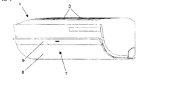
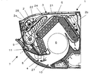
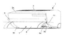
図1は本実施形態のセパレート型空気調和機の室内ユニットの運転停止時の導風パネルの姿勢を示す斜視図、図2は同じくその側面断面図である。図3は室内ユニットの導風パネル開姿勢を示す斜視図、図4は室内ユニットのカバーパネル開姿勢を示す斜視図である。 FIG. 1 is a perspective view showing the posture of the wind guide panel when the operation of the indoor unit of the separate type air conditioner of this embodiment is stopped, and FIG. 2 is a side sectional view of the same. FIG. 3 is a perspective view showing the air guide panel opening posture of the indoor unit, and FIG. 4 is a perspective view showing the cover panel opening posture of the indoor unit.
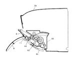
図5は運転停止時の導風パネルの覆い姿勢を示す前面パネルの側面断面図、図6は導風パネルの導風姿勢を示す前面パネルの側面断面図、図7は同じく導風パネルの回動機構を示す前面パネルの側面断面図、図8はカバーパネルの開姿勢を示す前面パネルの側面断面図、図9は同じく保持機構を示す前面パネルの側面断面図、図10はカバーパネル回動機構を示す前面パネルの側面断面図、図11はギヤボックス内部の断面図、図12はギヤボックスの側面図、図13はカバーパネルの側面断面図である。 FIG. 5 is a side sectional view of the front panel showing the covering position of the wind guide panel when the operation is stopped, FIG. 6 is a side sectional view of the front panel showing the wind guiding position of the wind guiding panel, and FIG. 8 is a side sectional view of the front panel showing the opening posture of the cover panel, FIG. 9 is a side sectional view of the front panel showing the holding mechanism, and FIG. 10 is a rotation of the cover panel. 11 is a side sectional view of the gear box, FIG. 12 is a side view of the gear box, and FIG. 13 is a side sectional view of the cover panel.
室内ユニット1は、図2に示すように、前面パネル2aと後板2b(キャビネット)とから箱状のケーシングが構成される。
As shown in FIG. 2, the
前面パネル2aは、背面が開放した箱状のものであって、上面に空気の吸込口3が形成され、前面下部に空気の吹出口4が形成される。後板2bは、冷凍サイクルの主要部品である熱交換器5や、室内ファン6を据え付ける。
The
ケーシング2の内部には、吸込口3から吹出口4に至る内部空気通路が形成され、この内部空気通路に熱交換器5と室内ファン6とが配設される。内部空気通路は、ケーシング上面の吸込口3から吸込んだ室内の空気をフィルタを通した後、熱交換器5で熱交換し、冷風又は温風として室内ファン6によって吹出口4から室内側に放出されるものである。
An internal air passage extending from the
室内ファン6は、クロスフローファンであって、その回転軸の軸方向が左右方向とされる。室内ファン6は、内部空気通路において熱交換器5よりも吹出口4側に配置される。
The indoor fan 6 is a crossflow fan, and the axial direction of the rotation axis is the left-right direction. The indoor fan 6 is disposed closer to the outlet 4 than the
吸込口3には、吸込んだ室内の空気から塵埃を除去するフィルタ21と、このフィルタ21を清掃する清掃装置22とが設けられる。フィルタ清掃装置22は、ケーシング2内でフィルタ21を側面視でU字形に湾曲した移動案内路24で移動させ、該移動案内路24に面した塵埃除去ボックス25の端部から吸引ファンにより、フィルタ21と略平行方向(左右方向)に空気を流すことで、フィルタ21に付着した塵埃を除去する。この際、塵埃除去ボックス内に回転ブラシを設け、フィルタ21に付着した塵埃を掻き取るようにしてもよい。
The
吹出口4には、縦ルーバと横ルーバとからなる公知構造の風向変更装置27が設けられ、吹出口4から吹出す風の向きを変更することができるようになっている。
The blower outlet 4 is provided with a wind
吹出口4には、風向変更装置27とは別に、ケーシング2の前面で吹出口4から吹出す風を遠方に導く導風パネル7が設けられる。導風パネル7は、その下端がケーシング2に対して第1の回動軸10周りに開閉回動自在に軸支される。また、導風パネル7を第1の回動軸10周りに回動する導風パネル回動機構30が設けられる。
In addition to the wind
導風パネル7は、第1の回動軸10周りに回動により、吹出口4から略水平方向に配置されて吹出口4から吹出す空気を略水平方向に導く導風姿勢と、ケーシング2の前面に沿って配置され、吹出口4を含むケーシングの前面の少なくとも下半分を覆う覆い姿勢とに切換え自在とされる。
The
導風パネル7の導風姿勢は、主として、冷房運転時に吹出口4から吹出された風を導風パネル7に沿って略水平方向ないし斜め上方に導き、室内の天井に沿って遠方に空気を導くときに採用される。
The wind guide posture of the
導風パネル7は、その覆い姿勢で、ケーシング2の前面下部から前面にかけて、吹出口4及びその周辺部分を被覆するように設置される。すなわち、導風パネル7は、吹出口4よりも大きく形成されており、ケーシング2の前面のほぼ全域を覆う大きさとされている。
The
導風パネル回動機構30は、図7に示すように、ケーシング2のギヤボックス35から出退自在に突出する回動アーム31と、該回動アーム31に形成されたラックギヤ32に噛合する駆動ギヤ33と、該駆動ギヤ33を回転駆動するステッピングモータ等からなるアーム駆動モータ34(図12参照)とを備えている。
As shown in FIG. 7, the wind guide
回動アーム31は、側面視で横く字形に形成される。回動アーム31の後端側の上面にはラックギヤ32が形成される。ラックギヤ32は、第1の回動軸10を中心に円弧状に形成される。駆動ギヤ33は、ラックギヤ32に噛合う。ラックギヤ32及び駆動ギヤ33は前面パネル2aの吹出口4の端部空間部に設置されたギヤボックス35に内装される。
The
回動アーム31の先端には、導風パネル7の延長パネル9に形成された横軸37に係脱自在に係合する係合フック38が形成され、導風パネル7がケーシング2に着脱自在に取り付けられている。
An
また、導風パネル7の第1の回動軸10は、ケーシング2の断面C字形の軸受部39に対して係脱自在に係止され、導風パネル7が吹出口4から取り外し自在とされる。導風パネル7を吹出口4から取り外すと、吹出口4の内部の清掃が容易となる。
Further, the first
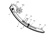
さらに、導風パネル7は、カバーパネル8と延長パネル9とに分割される。カバーパネル8は、主に吹出口4を含むケーシングの前面の左右方向でほぼ全域を覆うように構成される。延長パネル9は、その一部がカバーパネル8の上側に位置しケーシングの前面の左右方向でほぼ全域に覆うように構成される。また、カバーパネル8は、延長パネルに対して第2の回動軸11周りに回動可能に支持される。そして、カバーパネル8を延長パネル9に対して第2の回動軸11周りに回動するカバーパネル回動機構40が設けられる。
Further, the
カバーパネル回動機構40は、ケーシング2側に配設された駆動モータ41と、該モータ41の駆動力をカバーパネル側に伝達するギヤ列42a〜42hとを備える。また、カバーパネル8の回動時にカバーパネル側のギヤ列42g、42hの一部42gがケーシング側のギヤ42a〜42fとの噛合から離脱するのを防止する保持機構44が設けられる。
The cover
保持機構44は、カバーパネル8側のギヤ42gの回転軸を抱き込む係合フック45と、該係合フック45を前記ギヤの回転軸に対して係脱自在に回動させるフック駆動機構46とを備える。
The holding
係合フック駆動機構46は、ケーシング2側に配設された駆動モータ47と、該モータ47の駆動力をカバーパネル側に伝達するギヤ列48a〜48dとを備える。
The engagement
ギヤ列42a〜42fおよびギヤ列48a〜48dは、図11に示すように、ギヤボックス35に内装される。また、ギヤボックス35には、駆動モータ34、43、47が取り付けられる。
The
延長パネル9は、その両端部に板状のパネルベース9bが吹出口4の湾曲形状に合わせて湾曲されつつ下方へ垂設される。パネルベース9bの下端部には第1の回動軸10が設けられる。また、パネルベース9b間に吹出口から吹出す空気の通気部9aが設けられる。パネルベース9bの上端部には、第2の回動軸11が回動自在に軸支されている。
The
カバーパネル8は、延長パネル9と略直線状に配置されて一体的に連接された閉姿勢と、延長パネル9に対して第2の回動軸11周りに開回動して開放された開姿勢とに切換え自在とされる。
The
カバーパネル8を延長パネル9に対して閉姿勢に保持する係止機構50が設けられる。係止機構50は、カバーパネル8に設けられた係止爪51と、該係止爪51を係脱自在に係止する係合穴52付きの係止レバー53と、係止レバー53を係止方向に付勢する付勢手段としてのばね54とから構成される。
A
また、フック駆動機構46からの動力を利用して係止レバー53を付勢手段であるばね54に抗して離脱方向に移動させるピン55が設けられる。このピン55は、保持機構44に動力を伝達するギヤ列48a〜48dの中間地点で、軸56周りに回動するカム57の先端に形成される。カム57の回動により、その先端に形成されたピン55が係止レバー53をばね54に抗して押し、パネルベース9bに対してカバーパネル8を解放する。
Further, a
また、導風パネル7は、吹出口4の背面側の湾曲した通路壁に連続して風を遠方に導くことができるように、カバーパネル8が側面視で凹曲面形状に形成され、逆に、延長パネル9では、カバーパネル8から導かれた風がケーシング上面の吸込口3に吸込まれてショートサーキットを起こさないように内側に凸曲面形状に形成される。
Further, the
また、カバーパネル8および延長パネル9は、吹出口4から導かれる冷風と室内の空気との接触により導風パネル7の表側に結露するのを防止するため、その内側が断熱ポリウレタンフォームで成形される。
Further, the
上記構成において、運転停止時には、図1、図2および図5に示すように、導風パネル7がケーシング2の前面に沿って吹出口を覆う覆い姿勢になっている。この状態では、導風パネル7はケーシング2のほぼ前面に配置された状態となっている。
In the above configuration, when the operation is stopped, the
冷房運転時に導風パネル7を第1の回動軸10周りに回動して導風姿勢にすると、吹出口4から吹出した空気は、略水平方向の導風パネル7により、略水平方向ないし斜め上方へ遠方まで飛ばすことができる。したがって、室内ユニットを天井近くの壁面に据え付けた場合、吹出口4から吹出した冷風は天井面に沿って室内全体に行き渡り、室内全体を冷房することができる。
When the
この状態を図3、図6及び図7に示す。導風パネル7を運転停止時の吹出口4を覆う覆い姿勢から略水平方向に回動した導風姿勢に切り換えるには、導風パネル回動機構30を動作させる。駆動モータ34を駆動すると、そのモータ軸に連結されたギヤ33が回転し、このギヤ33に噛合うラックギヤ32を有する回動アーム31が第1の回動軸10を中心として前方に回動移動する。回動アーム31の先端係合フック38が延長パネル9の裏面のピン37に係合しているため、回動アーム31に押されて導風パネル7は、第1の回動軸10周りに開回動する。
This state is shown in FIG. 3, FIG. 6 and FIG. In order to switch the
このとき、カバーパネル8を延長パネル9に対して閉姿勢に保持する係止機構50が、図13に示すように、ばね54により係止爪51を係合穴52に係止した状態を保持するので、カバーパネル8と延長パネル9とは一体的に移動する。
At this time, the
また、カバーパネル回動機構40では、保持機構44の係合フック45が導風パネル7側のギヤ42gの回転軸を抱き込む姿勢から解除されているため、導風パネル7はこれらの機構に拘束されずに第1の回動軸10周りに開回動することができる。
Further, in the cover
一方、暖房運転時や急速冷風を行いたい場合、カバーパネル8を第2の回動軸11周りに開回動すると、カバーパネル8が垂直方向に向き、吹出口4から吹出した風が下方に導かれる。カバーパネル8の回動姿勢は種々変更することができる。例えば、カバーパネル8を最も開回動した「斜め下」姿勢から「下向き」、「真下」、そして「後向き」姿勢と順次閉方向に回動することができる。
On the other hand, when heating operation or quick cool air is desired, when the
この状態を図8〜図10に示す。図8はカバーパネル回動機構40の全体を示すものである。図9はカバーパネル8の回動時にカバーパネル側のギヤ列42g、42hの一部42gがケーシング側のギヤ42a〜42fとの噛合から離脱するのを防止する保持機構44のギヤ列を示す。また、この保持機構44の駆動力を利用したカバーパネル8を延長パネル9に対して閉姿勢に保持する係止機構50についても図示する。図10はカバーパネル8の回動機構40のギヤ列を示す。
This state is shown in FIGS. FIG. 8 shows the entire cover
カバーパネル8を閉姿勢から開姿勢に切り換えるには、まず、保持機構44のモータ47を駆動する。このモータ47の駆動により、そのモータ軸に直結しているギヤ48aが回転し、そのギヤ列48b〜48dまで動力が伝達される。その途中には、係止機構50のカム57があり、このカムが回転することにより、ピン55が係止レバー53をばね54に抗して移動させるので、係止レバー53の係合穴52に係止していた係止爪51が外れる。
In order to switch the
また、保持機構44のギヤ列48a〜48dに動力が伝達されると、係合フック45が回転し、カバーパネル8側のギヤ48gの回転軸を抱き込み、ケーシング側のギヤ列との噛合いを確保する。
Further, when power is transmitted to the
次に、カバーパネル回動機構40を駆動する。カバーパネル回動機構40では、その駆動モータ41からの駆動力がギヤ列42a〜42hに伝達され、最終ギヤ42hが一体化された第2の回動軸11が回転することになる。この回転によりカバーパネル8は第2の回動軸11周りに開回動する。
Next, the cover
なお、図5に示す運転停止状態で、導風パネル7を斜め上方に持ち上げ、延長パネル9の横軸37から回動アーム31を取り外し、また、ケーシング2の軸受部39から第1の回動軸10を取り外せば、導風パネル7を吹出口4から取り外すことができる。これにより、吹出口4が大きく開口されるので、ルーバを備えた風向変更装置27などの清掃を容易に行うことができる。
5, the
また、カバーパネル回動機構40として、導風パネル回動機構と同様に回動アームを用いることもできるが、本実施形態では、第2の回動軸11の周りのギヤ列によりカバーパネル8を開閉駆動している。これは、カバーパネル8を駆動するギヤ列42a〜42hのほとんどがギヤボックス35内に隠れ、露出部分を少なくすることができるためである。これにより、使用者側からはほとんど見えず、外観上好ましい回動機構を提供することができる。
Further, as the cover
また、導風パネルが第1の回動軸10を中心に回動して水平または上方に引き出す姿勢をとった後、閉成する場合、ギヤ42gとギヤ42fが再度噛合うこととなる。このとき、ギヤのバックラッシュなどの影響で、ギヤ42gとギヤ42fがうまく噛合わない場合が生じるおそれがある。この場合、モータ43を駆動っしてギヤ42aを回転させ、さらに、ギヤ42fを若干量、例えばギヤ42fの歯ピッチの半分程度を、導風パネル7の閉成直前に回転させることにより、ギヤ42gとギヤ42fとをうまく噛合わせることができる。
Further, when the wind guide panel is rotated about the
また、本実施形態の導風パネル回動機構30やカバーパネル回動機構40は、導風パネル7の左右方向の両端部にそれぞれ設けると、開閉動作のバランスが取れるので望ましいが、片側のみに設けても差し支えない。あるいは、導風パネル回動機構30やカバーパネル回動機構40を左右両端に分けて配置してもよい。
In addition, it is desirable that the wind guide
なお、本発明は、上記実施形態に限定されるものではなく、本発明の範囲内で多くの修正・変更を加えることができるのは勿論である。例えば、カバーパネルと延長パネルとを一体化する係止機構50において、係止爪は、カバーパネルと延長パネルのパネルベース側とのいずれか一方に設け、他方に係止爪を係脱自在に係止する係合穴付きの係止レバーを設ければよい。
Note that the present invention is not limited to the above-described embodiment, and it is needless to say that many modifications and changes can be made within the scope of the present invention. For example, in the
1 室内ユニット
2 ケーシング
3 吸込口
4 吹出口
5 熱交換器
6 室内ファン
7 導風パネル
8 カバーパネル
9 延長パネル
9a 通気部
9b パネルベース
10 第1回動軸
11 第2回動軸
21 フィルタ
22 フィルタ清掃装置
24 移動案内路
25 塵埃除去ボックス
30 導風パネル回動機構
31 回動アーム
32 ラックギヤ
33 駆動ギヤ
34 駆動モータ
35 ギヤボックス
37 横軸
38 係合フック
39 軸受部
40 カバーパネル回動機構
41 駆動モータ
42a〜42h ギヤ
44 保持機構
45 係合フック
46 フック駆動機構
47 駆動モータ
48a〜48d ギヤ
50 係止機構
51 係止爪
52 係合穴
53 係止レバー
54 ばね(付勢手段)
55 ピン
56 軸
57 カム
DESCRIPTION OF
55
Claims (4)
前記導風パネルは、カバーパネルと延長パネルとに分割され、前記カバーパネルは、主に吹出口を含むケーシングの前面の左右方向でほぼ全域を覆うように構成され、前記延長パネルは、その一部が前記カバーパネルの上側に位置しケーシングの前面の左右方向でほぼ全域に覆うように構成され、前記カバーパネルが前記延長パネルに対して第2の回動軸周りに回動可能に支持され、前記カバーパネルを延長パネルに対して第2の回動軸周りに回動するカバーパネル回動機構が設けられたことを特徴とする空気調和機。 A wind guide panel for guiding the air blown from the outlet of the casing in the blowing direction, the lower end of the wind guide panel being pivotally supported so as to be openable and closable around a first rotation axis with respect to the casing; An air guide panel rotating mechanism for rotating the air guide panel around the first rotation axis;
The wind guide panel is divided into a cover panel and an extension panel, and the cover panel is configured to cover almost the entire region in the left-right direction of the front surface of the casing mainly including the air outlet, and the extension panel is one of the covers. The cover is positioned on the upper side of the cover panel so as to cover almost the entire area in the left-right direction of the front surface of the casing, and the cover panel is supported by the extension panel so as to be rotatable around a second rotation axis. An air conditioner characterized in that a cover panel rotation mechanism is provided for rotating the cover panel around a second rotation axis with respect to the extension panel .
前記導風パネルは、カバーパネルと延長パネルとに分割され、
前記延長パネルは、その両端部に板状のパネルベースが下方に突設されると共に両パネルベース間に吹出口から吹出す空気の通気部が設けられ、かつ前記パネルベースの下端部には前記第1の回動軸が設けられると共に前記パネルベースの上端部には第2の回動軸を介して前記カバーパネルの上端部が回動可能に軸支され、前記カバーパネルを前記延長パネルに対して第2の回動軸周りに回動するカバーパネル回動機構が設けられ、
前記カバーパネルは、前記パネルベースを覆うと共に前記延長パネルのパネルベースよりも上側部分と略直線状に配置されて一体的に連接された閉姿勢と、パネルベースに対して第2の回動軸周りに開回動して開放された開姿勢とに切換え可能とされ、前記カバーパネルの閉姿勢で、前記導風パネルはケーシングの前面下部から前面にかけて吹出口及びその周辺を被覆するように設置されたことを特徴とする空気調和機。 A wind guide panel for guiding the air blown from the outlet of the casing in the blowing direction, the lower end of the wind guide panel being pivotally supported so as to be openable and closable around a first rotation axis with respect to the casing; An air guide panel rotating mechanism for rotating the air guide panel around the first rotation axis;
The wind guide panel is divided into a cover panel and a prolongation panel,
The extension panel is provided with a plate-like panel base projecting downward at both ends thereof, and an air ventilation portion that is blown out from the air outlet between the two panel bases. the upper end portion of said panel base with the first rotation shaft are provided upper end of the cover panel via the second rotating shaft is rotatably supported, said cover panel to said extension panel In contrast, a cover panel rotation mechanism that rotates around the second rotation axis is provided,
The cover panel covers the panel base and is disposed in a substantially straight line with the upper portion of the extension panel and connected integrally therewith, and a second rotating shaft with respect to the panel base. It is possible to switch to an open position that is opened by rotating around, and in the closed position of the cover panel, the wind guide panel is installed so as to cover the air outlet and its periphery from the lower front of the casing to the front An air conditioner characterized by being made .
Priority Applications (1)
| Application Number | Priority Date | Filing Date | Title |
|---|---|---|---|
| JP2006326666A JP4921135B2 (en) | 2006-12-04 | 2006-12-04 | Air conditioner |
Applications Claiming Priority (1)
| Application Number | Priority Date | Filing Date | Title |
|---|---|---|---|
| JP2006326666A JP4921135B2 (en) | 2006-12-04 | 2006-12-04 | Air conditioner |
Publications (3)
| Publication Number | Publication Date |
|---|---|
| JP2008138962A JP2008138962A (en) | 2008-06-19 |
| JP2008138962A5 JP2008138962A5 (en) | 2009-05-14 |
| JP4921135B2 true JP4921135B2 (en) | 2012-04-25 |
Family
ID=39600615
Family Applications (1)
| Application Number | Title | Priority Date | Filing Date |
|---|---|---|---|
| JP2006326666A Expired - Fee Related JP4921135B2 (en) | 2006-12-04 | 2006-12-04 | Air conditioner |
Country Status (1)
| Country | Link |
|---|---|
| JP (1) | JP4921135B2 (en) |
Cited By (2)
| Publication number | Priority date | Publication date | Assignee | Title |
|---|---|---|---|---|
| WO2019134243A1 (en) * | 2018-01-05 | 2019-07-11 | 青岛海尔空调器有限总公司 | Wall-mounted air conditioner indoor unit |
| WO2020125264A1 (en) * | 2018-12-18 | 2020-06-25 | 青岛海尔空调器有限总公司 | Air duct assembly and air conditioner |
Families Citing this family (16)
| Publication number | Priority date | Publication date | Assignee | Title |
|---|---|---|---|---|
| CN103512088B (en) * | 2012-06-27 | 2017-04-12 | 珠海格力电器股份有限公司 | Vertical cabinet type air-conditioner |
| CN103673242B (en) * | 2012-09-14 | 2016-11-09 | 珠海格力电器股份有限公司 | The air deflection assemblies of air-conditioner and air-conditioner |
| CN203258820U (en) * | 2013-01-16 | 2013-10-30 | 珠海格力电器股份有限公司 | Panel driving mechanism and air conditioning fission machine having same |
| CN103982997A (en) * | 2014-04-24 | 2014-08-13 | 珠海格力电器股份有限公司 | Air guide device and air conditioner |
| CN203880890U (en) * | 2014-06-17 | 2014-10-15 | 珠海格力电器股份有限公司 | Air sweeping component and air conditioner with same |
| JP6359919B2 (en) * | 2014-08-22 | 2018-07-18 | シャープ株式会社 | Air conditioner |
| CN104566652A (en) * | 2015-01-16 | 2015-04-29 | 广东美的制冷设备有限公司 | Wall-mounted type air conditioner |
| JP6264347B2 (en) * | 2015-09-10 | 2018-01-24 | ダイキン工業株式会社 | Air conditioning indoor unit |
| CN105546658A (en) * | 2016-02-01 | 2016-05-04 | 珠海格力电器股份有限公司 | Air-conditioner indoor unit and air conditioner with the same |
| CN105650734A (en) * | 2016-02-16 | 2016-06-08 | 珠海格力电器股份有限公司 | Air conditioner |
| CN106440295A (en) * | 2016-11-11 | 2017-02-22 | 珠海格力电器股份有限公司 | Sectional air guide plate and air conditioner with air guide plate |
| CN108800496B (en) * | 2017-04-26 | 2019-09-03 | 珠海格力电器股份有限公司 | Air conditioner |
| CN107830618B (en) * | 2017-10-26 | 2023-11-21 | 珠海格力电器股份有限公司 | Air guide device and air conditioner applying same |
| CN108050599B (en) * | 2018-01-04 | 2023-07-21 | 奥克斯空调股份有限公司 | Air conditioner air ducting and air conditioner |
| CN111141016B (en) * | 2020-01-06 | 2023-12-15 | 珠海格力电器股份有限公司 | Wind shielding mechanism, air supply system with same, air conditioner and control method |
| CN114439772B (en) * | 2022-03-28 | 2022-11-15 | 西安交通大学 | Bionic wing-shaped flow distribution net, low-noise cross flow fan and air conditioner |
Family Cites Families (6)
| Publication number | Priority date | Publication date | Assignee | Title |
|---|---|---|---|---|
| JPH0629939B2 (en) * | 1984-12-12 | 1994-04-20 | 富士写真フイルム株式会社 | Color film test method |
| JPH0933095A (en) * | 1995-07-20 | 1997-02-07 | Fujitsu General Ltd | Air conditioner |
| JP2001254988A (en) * | 2000-03-13 | 2001-09-21 | Matsushita Electric Ind Co Ltd | Air direction controller for air conditioner |
| JP3669322B2 (en) * | 2000-11-21 | 2005-07-06 | ダイキン工業株式会社 | Air conditioner indoor unit |
| JP2004012060A (en) * | 2002-06-10 | 2004-01-15 | Mitsubishi Heavy Ind Ltd | Indoor unit for air conditioner and air conditioner |
| JP2006002984A (en) * | 2004-06-16 | 2006-01-05 | Fujitsu General Ltd | Air conditioner |
-
2006
- 2006-12-04 JP JP2006326666A patent/JP4921135B2/en not_active Expired - Fee Related
Cited By (2)
| Publication number | Priority date | Publication date | Assignee | Title |
|---|---|---|---|---|
| WO2019134243A1 (en) * | 2018-01-05 | 2019-07-11 | 青岛海尔空调器有限总公司 | Wall-mounted air conditioner indoor unit |
| WO2020125264A1 (en) * | 2018-12-18 | 2020-06-25 | 青岛海尔空调器有限总公司 | Air duct assembly and air conditioner |
Also Published As
| Publication number | Publication date |
|---|---|
| JP2008138962A (en) | 2008-06-19 |
Similar Documents
| Publication | Publication Date | Title |
|---|---|---|
| JP4921135B2 (en) | Air conditioner | |
| TWI269015B (en) | Air conditioner | |
| KR100776595B1 (en) | Air-conditioner | |
| JP6289740B2 (en) | Air conditioner indoor unit | |
| JP5015322B2 (en) | Air conditioner indoor unit | |
| WO2016157295A1 (en) | Indoor unit for air conditioner | |
| JP6381782B2 (en) | Air conditioner indoor unit | |
| JP6289739B2 (en) | Air conditioner indoor unit | |
| JP2007107728A (en) | Air conditioner | |
| JP3207737B2 (en) | Air conditioner | |
| JP6385562B2 (en) | Air conditioner indoor unit | |
| JP2010071502A (en) | Air conditioner | |
| JP4020681B2 (en) | Air conditioner | |
| JP6609715B2 (en) | How to remove the dust storage box from the main body of the air cleaning mechanism | |
| JP4847299B2 (en) | Air conditioner | |
| JP6490260B2 (en) | Air conditioner indoor unit | |
| JP2011202931A (en) | Indoor unit of air conditioner | |
| JP2000039171A (en) | Air conditioner | |
| JP2006125723A (en) | Air conditioner | |
| KR100737318B1 (en) | Air-conditioner | |
| JP4313184B2 (en) | Air conditioner indoor unit | |
| JP2012042181A (en) | Indoor unit of air conditioner | |
| JP2011163613A (en) | Air conditioner | |
| KR100760207B1 (en) | Air-conditioner | |
| JP6320626B2 (en) | Air conditioner indoor unit |
Legal Events
| Date | Code | Title | Description |
|---|---|---|---|
| A521 | Written amendment |
Free format text: JAPANESE INTERMEDIATE CODE: A523 Effective date: 20090327 |
|
| A621 | Written request for application examination |
Free format text: JAPANESE INTERMEDIATE CODE: A621 Effective date: 20090327 |
|
| A977 | Report on retrieval |
Free format text: JAPANESE INTERMEDIATE CODE: A971007 Effective date: 20110413 |
|
| A131 | Notification of reasons for refusal |
Free format text: JAPANESE INTERMEDIATE CODE: A131 Effective date: 20110517 |
|
| A521 | Written amendment |
Free format text: JAPANESE INTERMEDIATE CODE: A523 Effective date: 20110707 |
|
| TRDD | Decision of grant or rejection written | ||
| A01 | Written decision to grant a patent or to grant a registration (utility model) |
Free format text: JAPANESE INTERMEDIATE CODE: A01 Effective date: 20120110 |
|
| A01 | Written decision to grant a patent or to grant a registration (utility model) |
Free format text: JAPANESE INTERMEDIATE CODE: A01 |
|
| A61 | First payment of annual fees (during grant procedure) |
Free format text: JAPANESE INTERMEDIATE CODE: A61 Effective date: 20120202 |
|
| R150 | Certificate of patent or registration of utility model |
Ref document number: 4921135 Country of ref document: JP Free format text: JAPANESE INTERMEDIATE CODE: R150 Free format text: JAPANESE INTERMEDIATE CODE: R150 |
|
| FPAY | Renewal fee payment (event date is renewal date of database) |
Free format text: PAYMENT UNTIL: 20150210 Year of fee payment: 3 |
|
| LAPS | Cancellation because of no payment of annual fees |