EP3348918A1 - Outdoor unit - Google Patents
Outdoor unit Download PDFInfo
- Publication number
- EP3348918A1 EP3348918A1 EP16843780.4A EP16843780A EP3348918A1 EP 3348918 A1 EP3348918 A1 EP 3348918A1 EP 16843780 A EP16843780 A EP 16843780A EP 3348918 A1 EP3348918 A1 EP 3348918A1
- Authority
- EP
- European Patent Office
- Prior art keywords
- housing
- cover
- outdoor unit
- controller
- pair
- Prior art date
- Legal status (The legal status is an assumption and is not a legal conclusion. Google has not performed a legal analysis and makes no representation as to the accuracy of the status listed.)
- Withdrawn
Links
Images


Classifications
-
- F—MECHANICAL ENGINEERING; LIGHTING; HEATING; WEAPONS; BLASTING
- F24—HEATING; RANGES; VENTILATING
- F24F—AIR-CONDITIONING; AIR-HUMIDIFICATION; VENTILATION; USE OF AIR CURRENTS FOR SCREENING
- F24F1/00—Room units for air-conditioning, e.g. separate or self-contained units or units receiving primary air from a central station
- F24F1/06—Separate outdoor units, e.g. outdoor unit to be linked to a separate room comprising a compressor and a heat exchanger
- F24F1/56—Casing or covers of separate outdoor units, e.g. fan guards
-
- F—MECHANICAL ENGINEERING; LIGHTING; HEATING; WEAPONS; BLASTING
- F24—HEATING; RANGES; VENTILATING
- F24F—AIR-CONDITIONING; AIR-HUMIDIFICATION; VENTILATION; USE OF AIR CURRENTS FOR SCREENING
- F24F1/00—Room units for air-conditioning, e.g. separate or self-contained units or units receiving primary air from a central station
- F24F1/06—Separate outdoor units, e.g. outdoor unit to be linked to a separate room comprising a compressor and a heat exchanger
- F24F1/08—Compressors specially adapted for separate outdoor units
- F24F1/10—Arrangement or mounting thereof
-
- F—MECHANICAL ENGINEERING; LIGHTING; HEATING; WEAPONS; BLASTING
- F24—HEATING; RANGES; VENTILATING
- F24F—AIR-CONDITIONING; AIR-HUMIDIFICATION; VENTILATION; USE OF AIR CURRENTS FOR SCREENING
- F24F1/00—Room units for air-conditioning, e.g. separate or self-contained units or units receiving primary air from a central station
- F24F1/06—Separate outdoor units, e.g. outdoor unit to be linked to a separate room comprising a compressor and a heat exchanger
- F24F1/14—Heat exchangers specially adapted for separate outdoor units
- F24F1/16—Arrangement or mounting thereof
-
- F—MECHANICAL ENGINEERING; LIGHTING; HEATING; WEAPONS; BLASTING
- F24—HEATING; RANGES; VENTILATING
- F24F—AIR-CONDITIONING; AIR-HUMIDIFICATION; VENTILATION; USE OF AIR CURRENTS FOR SCREENING
- F24F1/00—Room units for air-conditioning, e.g. separate or self-contained units or units receiving primary air from a central station
- F24F1/06—Separate outdoor units, e.g. outdoor unit to be linked to a separate room comprising a compressor and a heat exchanger
- F24F1/20—Electric components for separate outdoor units
- F24F1/22—Arrangement or mounting thereof
-
- F—MECHANICAL ENGINEERING; LIGHTING; HEATING; WEAPONS; BLASTING
- F24—HEATING; RANGES; VENTILATING
- F24F—AIR-CONDITIONING; AIR-HUMIDIFICATION; VENTILATION; USE OF AIR CURRENTS FOR SCREENING
- F24F1/00—Room units for air-conditioning, e.g. separate or self-contained units or units receiving primary air from a central station
- F24F1/06—Separate outdoor units, e.g. outdoor unit to be linked to a separate room comprising a compressor and a heat exchanger
- F24F1/38—Fan details of outdoor units, e.g. bell-mouth shaped inlets or fan mountings
Definitions
- An air conditioner which cools and heats an office, a factory and so forth is equipped with an indoor unit which is installed indoors and an outdoor unit which is installed outdoors.
- the outdoor unit makes a refrigerant which passes through refrigerant piping and outdoor air exchange heat by a heat exchanger provided in a housing, evaporates or condenses the refrigerant and thereafter supplies the refrigerant to the indoor unit.
- the indoor unit cools or heats indoor air by utilizing latent heat of the refrigerant supplied from the outdoor unit.
- the outdoor unit is configured by continuously installing the plurality of outdoor units, there is such an issue that the total installation area of the outdoor units which are continuously installed is increased. Therefore, there are cases where a configuration is made in such a manner that a height of the heat exchanger is made large or the heat exchanger extends not only to a back face of a housing but also up to side faces and a front face of the housing in order to secure a necessary heat exchanger capacity while suppressing the installation area of the single-body outdoor unit.
- Patent Literature 1 Japanese Patent No. 5380503
- the heat exchanger is made to extend from the back face to the side faces of the housing and thereby it is possible to secure the predetermined heat transfer area without increasing the height dimension of the outdoor unit.
- An object of the present invention is to obtain an outdoor unit of an air conditioner or a refrigerator which makes maintenance of the strength of the housing and installation with the saved installation area possible after securing a necessary heat exchange performance by making the heat exchanger extend to the whole areas of the back face and both of the side faces of the housing.
- this outdoor unit is configured by including a fan which sucks and expels air, a heat exchanger, a compressor which compresses a refrigerant, a controller housing in which a controller which controls the fan or the compressor is built and a housing section which houses therein the heat exchanger, the compressor and the controller housing and to an upper face of which the fan is attached and is configured in such a manner that the housing section is equipped with one pair of left and right side covers which have two faces formed by being bent and which cover parts of side faces of the housing with one faces and cover parts of the front of the housing with the other faces and a maintenance panel which is detachably attached to parts of one pair of the left and right side covers which cover the parts of the front of the housing section and the controller housing is fixed with a fixing member to a position of a height at which the controller housing does not become an obstacle when the compressor is put out of and into the inside of the housing section,
- the present invention is configured in such a manner that, in an outdoor unit of an air conditioner or a refrigerator, a controller housing of the outdoor unit is fixed to upper parts of side covers which cover side faces and parts of the front of a housing of the outdoor unit so as to reinforce bending strength and torsional strength of the housing of the outdoor unit and to eliminate a thing which would become an obstacle when a compressor is put out of and into a front face of the housing of the outdoor unit and thereby assemblability and maintainability of the outdoor unit are improved.
- Embodiments of the present invention will be described by giving an outdoor unit of an air conditioner by way of example.
- 1 is a housing of the outdoor unit 100 of the air conditioner
- 2 is a fan which performs air-sucking into and air-expelling out of the housing
- 3-1 and 3-2 are heat exchangers respectively
- 4 is a compressor
- 5 is an accumulator
- 6 is a header pipe
- 7 is a controller housing and control circuit components are housed therein.
- 8 is a housing left cover which covers left-side front face and side face of the housing 1
- 81 is a housing left rear cover which covers the left rear side of the housing 1
- 9 is a housing right cover which convers right-side front face and side face of the housing 1
- 91 is a housing right rear cover of the right rear side of the housing 1
- 10 is a baseplate onto which the compressor 4 and the accumulator 5 are loaded and fixed
- 11 is a fixture
- 12 is a maintenance panel which covers the front face of the housing and is detachably attached to the housing 1.
- the housing left cover 8, the housing left rear cover 81, the housing right cover 9 and the housing right rear cover 91 are each fastened to the edge part 101 which is bent to the upper side of the end part of the baseplate 10 with a screw or a bolt in the vicinity of a lower end part thereof and the vicinity of an upper end part of each of them is fastened with a screw or a bolt and fixed to a top plate which is not illustrated and is attached to an upper face of the housing 1.
- the controller housing 7 which builds therein a control circuit part adapted to drive the compressor 4 and the fan motors is disposed above the housing 1 so as to run along the front thereof.
- the controller housing 7 is configured by a sheet metal member which houses therein electric components such as a circuit board and a terminal block of the not illustrated control circuit part and therefore is the heavy good. Also this controller housing 7 is held by the aforementioned housing left cover 8 and housing right cover 9.
- the two almost U-shaped heat exchangers 3-1 and 3-2 are arranged side by side on the left and the right viewing from the front of the housing 1 similarly to the fans 2 and are provided so as to surround the left and right fans 2 respectively.
- these heat exchangers 3-1 and 3-2 are provided along the side faces of the housing 1 except the front thereof on the left and the right respectively.
- bent lengths of the respective left and right heat exchangers 3-1 and 3-2 are configured to be longer on the housing side-face sides (the right-side face side and the left-side face side of the housing 1 in Fig. 2 ) and to be shorter on the housing inner sides (the sides on which they are connected with the header pipes 6).
- the heat exchangers 3-1 and 3-2 serve as air suction ports of the fans 2, it is necessary to form it into such a structure that it is possible to take the outdoor air into the housing 1 via the heat exchangers 3-1 and 3-2. Accordingly, it is formed into a structure that spaces are left between the housing left cover 8 and the housing left rear cover 81 and between the housing right cover 9 and the housing right rear cover 91 so as to attach them therebetween respectively. Therefore, the strength of the housing 1 is lowered in comparison with a case where the surrounding thereof is covered with a full cover.
- the first embodiment it is formed into a configuration that end parts 71 and 72 are formed on the both sides of the controller housing 7, and the end parts 71 and 72 on the both sides are fastened to a part of the housing left cover 8 which is bent to the front-face side of the housing 1 and a part of the housing right cover 9 which is bent to the front-face side of the housing 1 with at least one fixture 11 each.
- the fixture 11 for example, the one that a bolt is combined with a nut may be used.
- controller housing 7 is disposed upper part of the housing 1 and on the front of the housing 1, there is no thing which would become the obstacle when the compressor 4 is put out of and into the housing 1 from the front (the front face) thereof and it is possible to perform attachment and detachment of the compressor 4 with ease. Further, since it is excellent in maintainability and it is possible to dispose the compressor 4 on the center and on the front face of the housing 1, it is excellent in exchangeability in failure of the compressor 4 and the center of gravity of the whole housing 1 is well-balanced.
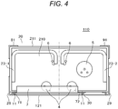
- Fig. 3 is a front sectional diagram of an outdoor unit 110 according to a second embodiment and Fig. 4 is a sectional diagram along the B-B line in Fig. 3 .
- parts to which the same symbols are assigned indicate the same parts.
- a stationary plate 30 is provided on the front of the housing 20 and on the right side from the width center of the housing 20 so as to compensate for the strength poverty of the housing left cover 28 and the housing right cover 29.
- the controller housing 7 is formed into a structure that the left-side end part 71 of the controller housing 7 is fastened to the housing left cover 28 and the right-side end part 72 of the controller housing 7 is fastened to the stationary plate 30 with at least one fixture 11 similarly to the first embodiment. It is possible to complement for the strength of each of them by configuring in this way.
- a maintenance panel 121 is attached to the front face of the housing 2 to which the controller housing 7 is attached so as to cover the front face of the housing 20 including the controller housing 7.
Landscapes
- Engineering & Computer Science (AREA)
- Chemical & Material Sciences (AREA)
- Combustion & Propulsion (AREA)
- Mechanical Engineering (AREA)
- General Engineering & Computer Science (AREA)
- Other Air-Conditioning Systems (AREA)
Abstract
Description
- The present invention relates to an outdoor unit of an air conditioner, a refrigerator and so forth and, in particular, relates to the outdoor unit of the air conditioner or the refrigerator by which it becomes possible to promote compactification, cost reduction and so forth.
- An air conditioner which cools and heats an office, a factory and so forth is equipped with an indoor unit which is installed indoors and an outdoor unit which is installed outdoors. The outdoor unit makes a refrigerant which passes through refrigerant piping and outdoor air exchange heat by a heat exchanger provided in a housing, evaporates or condenses the refrigerant and thereafter supplies the refrigerant to the indoor unit. The indoor unit cools or heats indoor air by utilizing latent heat of the refrigerant supplied from the outdoor unit.
- In a case where a comparatively large air-conditioning capacity is requested as in an air conditioner for building, a so-called modular-type form that one refrigerant system is configured by connecting a plurality of the outdoor units with one another has become mainstream in recent years.
- In a case of the modular-type one like this, since the outdoor unit is configured by continuously installing the plurality of outdoor units, there is such an issue that the total installation area of the outdoor units which are continuously installed is increased. Therefore, there are cases where a configuration is made in such a manner that a height of the heat exchanger is made large or the heat exchanger extends not only to a back face of a housing but also up to side faces and a front face of the housing in order to secure a necessary heat exchanger capacity while suppressing the installation area of the single-body outdoor unit.
- Incidentally, as related art of this kind, there is the one described in
Patent Literature 1 and so forth. - Patent Literature 1: Japanese Patent No.
5380503 - In the one according to the related art described in
Patent Literature 1 and so forth, the heat exchanger is made to extend from the back face to the side faces of the housing and thereby it is possible to secure the predetermined heat transfer area without increasing the height dimension of the outdoor unit. However, in such a case, it is necessary to provide a large opening in the housing which covers the side faces in order to expose the heat exchanger because the heat exchanger is made to extend up to the side faces of the housing. Consequently, there is such an issue that the area of a sheet metal member which supports the side faces of the housing is reduced and strength of the housing is lowered. - An object of the present invention is to obtain an outdoor unit of an air conditioner or a refrigerator which makes maintenance of the strength of the housing and installation with the saved installation area possible after securing a necessary heat exchange performance by making the heat exchanger extend to the whole areas of the back face and both of the side faces of the housing.
- In order to solve the above-described issue, in the present invention, in an outdoor unit of an air conditioner or a refrigerator, this outdoor unit is configured by including a housing with a fan being mounted and with a compressor and a heat exchanger being loaded on a bottom base, a controller housing in which a controller which controls the fan and the compressor is built and one pair of left and right side covers which have two faces formed by being bent and cover parts of side faces of the housing with one faces and cover parts of the front of the housing with the other faces and is configured in such a manner that the controller housing is fixed to a position of a height at which the controller housing does not become an obstacle when the compressor is put out of and into the inside of the housing, on an upper part of a face of at least one side cover which covers the part of the front of the housing in one pair of the left and right side covers.
- In addition, in order to solve the above-described issue, in the present invention, in an outdoor unit of air conditioner or refrigerator, this outdoor unit is configured by including a fan which sucks and expels air, a heat exchanger, a compressor which compresses a refrigerant, a controller housing in which a controller which controls the fan or the compressor is built and a housing section which houses therein the heat exchanger, the compressor and the controller housing and to an upper face of which the fan is attached and is configured in such a manner that the housing section is equipped with one pair of left and right side covers which have two faces formed by being bent and which cover parts of side faces of the housing with one faces and cover parts of the front of the housing with the other faces and a maintenance panel which is detachably attached to parts of one pair of the left and right side covers which cover the parts of the front of the housing section and the controller housing is fixed with a fixing member to a position of a height at which the controller housing does not become an obstacle when the compressor is put out of and into the inside of the housing section, on the inner side of the maintenance panel on a face of at least one side cover which covers the part of the front of the housing section in one pair of the left and right side covers.
- According to the present invention, the controller housing also serves to reinforce the housing of the outdoor unit and thereby it becomes possible to compensate for strength poverty of the cover of the housing without using an extra reinforcement member. In addition, since the controller housing is disposed above the housing and on the front of the housing of the outdoor unit, a thing which would become an obstacle when the compressor is put out of and into the housing of the outdoor unit from the front face thereof is not present and thereby it becomes possible to perform attachment and detachment of the compressor with ease.
-
-
Figure 1 is a front view of an air conditioning outdoor unit according to a first embodiment of the present invention. -
Figure 2 is a sectional diagram of the air conditioning outdoor unit according to the first embodiment of the present invention along the A-A line inFigure 2 . -
Figure 3 is a front view of an air conditioning outdoor unit according to a second embodiment of the present invention. -
Figure 4 is a sectional diagram of the air conditioning outdoor unit according to the second embodiment of the present invention along the B-B line inFigure 4 . - The present invention is configured in such a manner that, in an outdoor unit of an air conditioner or a refrigerator, a controller housing of the outdoor unit is fixed to upper parts of side covers which cover side faces and parts of the front of a housing of the outdoor unit so as to reinforce bending strength and torsional strength of the housing of the outdoor unit and to eliminate a thing which would become an obstacle when a compressor is put out of and into a front face of the housing of the outdoor unit and thereby assemblability and maintainability of the outdoor unit are improved.
- In all drawings for describing the present embodiments, the same symbols are assigned to things having the same functions and repetitive description thereof is omitted in principle. In the following, embodiments of the present invention will be described in detail on the basis of the drawings.
- However, the present invention shall not be interpreted by limiting to contents described in the following embodiments. A person skilled in the art would readily understand that a specific configuration thereof may be modified and altered within a range not deviating from the idea and the gist of the present invention.
- Embodiments of the present invention will be described by giving an outdoor unit of an air conditioner by way of example.
-
Fig. 1 is a front sectional diagram of anoutdoor unit 100 of an air conditioner 1000 according to a first embodiment andFig. 2 is a sectional diagram along the A-A line inFig. 1 . - In
Fig. 1 andFig. 2 , 1 is a housing of theoutdoor unit 100 of the air conditioner, 2 is a fan which performs air-sucking into and air-expelling out of thehousing 1, 3-1 and 3-2 are heat exchangers respectively, 4 is a compressor, 5 is an accumulator, 6 is a header pipe and 7 is a controller housing and control circuit components are housed therein. 8 is a housing left cover which covers left-side front face and side face of thehousing housing housing housing compressor 4 and theaccumulator 5 are loaded and fixed, 11 is a fixture, and 12 is a maintenance panel which covers the front face of the housing and is detachably attached to thehousing 1. - The
baseplate 10 is, an end part of a circumference is bent upward and thereby anedge part 101 is formed. Although various kinds of piping and electric wiring are stretched in thehousing 1, illustration thereof is omitted for simplification of illustration. - The housing left
cover 8, the housing leftrear cover 81, the housingright cover 9 and the housing rightrear cover 91 are each fastened to theedge part 101 which is bent to the upper side of the end part of thebaseplate 10 with a screw or a bolt in the vicinity of a lower end part thereof and the vicinity of an upper end part of each of them is fastened with a screw or a bolt and fixed to a top plate which is not illustrated and is attached to an upper face of thehousing 1. - In
Fig. 1 , twofans 2 are arranged above thehousing 1 of the air conditioning outdoor unit, side by side on the left and the right viewing from the housing front and are provided so as to expel air upward. - Containers such as the
compressor 4 and theaccumulator 5 are loaded in thehousing 1 and further they are fixed to thebaseplate 10 of thehousing 1. In addition, although not illustrated in the drawings, they are connected with a four-way valve adapted to change a flowing direction of a refrigerant which flows in the heat exchangers 3-1 and 3-2, the header pipes 6 (seeFig. 2 ) provided on end parts of the heat exchangers 3-1 and 3-2 and so forth by not illustrated refrigerant piping thereby to form a refrigerating cycle. - In
Fig. 1 , the housingleft cover 8 and the housingright cover 9 are provided on the front left side and right side of thehousing 1 respectively. As illustrated inFig. 2 , the housingleft cover 8 and the housingright cover 9 have faces which face the front side of the housing 1 (a lower-side face of thehousing 1 illustrated inFig. 2 ) and faces which face the side-face sides thereof (the right-side or left-side face of thehousing 1 illustrated inFig. 2 ) . Parts of the faces of the housingleft cover 8 and the housingright cover 9 which face the front side of thehousing 1 are shaped into stepped-forms of two steps. Although not illustrated in the drawings, the housing leftcover 8 and the housingright cover 9, and the housing leftrear cover 81 and the housing rightrear cover 91 play parts of supporting heavy goods which are disposed above thehousing 1 such as fan motors which rotate the fans, clamps which support the fan motors and shrouds which surround the fans. - In addition, in
Fig. 1 andFig. 2 , thecontroller housing 7 which builds therein a control circuit part adapted to drive thecompressor 4 and the fan motors is disposed above thehousing 1 so as to run along the front thereof. Thecontroller housing 7 is configured by a sheet metal member which houses therein electric components such as a circuit board and a terminal block of the not illustrated control circuit part and therefore is the heavy good. Also thiscontroller housing 7 is held by the aforementioned housingleft cover 8 and housingright cover 9. - In addition, in
Fig. 2 , the two almost U-shaped heat exchangers 3-1 and 3-2 are arranged side by side on the left and the right viewing from the front of thehousing 1 similarly to thefans 2 and are provided so as to surround the left andright fans 2 respectively. Incidentally, these heat exchangers 3-1 and 3-2 are provided along the side faces of thehousing 1 except the front thereof on the left and the right respectively. In addition, bent lengths of the respective left and right heat exchangers 3-1 and 3-2 are configured to be longer on the housing side-face sides (the right-side face side and the left-side face side of thehousing 1 inFig. 2 ) and to be shorter on the housing inner sides (the sides on which they are connected with the header pipes 6). - It is possible to secure the necessary volumes of the heat exchangers 3-1 and 3-2 without expanding the installation area of the
housing 1 by disposing the heat exchangers 3-1 and 3-2 along the back face and both of the left and right side faces of thehousing 1 in this way. However, since the heat exchangers 3-1 and 3-2 serve as air suction ports of thefans 2, it is necessary to form it into such a structure that it is possible to take the outdoor air into thehousing 1 via the heat exchangers 3-1 and 3-2. Accordingly, it is formed into a structure that spaces are left between the housingleft cover 8 and the housing leftrear cover 81 and between the housingright cover 9 and the housing rightrear cover 91 so as to attach them therebetween respectively. Therefore, the strength of thehousing 1 is lowered in comparison with a case where the surrounding thereof is covered with a full cover. - In addition, to put the
compressor 4 out of and into inside of thehousing 2, it is not possible to dispose a thing on the front face of the housing 1 (the lower-side face of thehousing 1 inFig. 2 ) which would become an obstacle when thecompressor 4 is put out of and into inside of thehousing 1 . Accordingly, there is no reinforcement on the front face of thehousing 1 when left as it is and thehousing 1 is formed into a structure which is fragile against bending and torsion. - Therefore, in the first embodiment, it is formed into a configuration that
end parts controller housing 7, and theend parts left cover 8 which is bent to the front-face side of thehousing 1 and a part of the housingright cover 9 which is bent to the front-face side of thehousing 1 with at least onefixture 11 each. As thefixture 11, for example, the one that a bolt is combined with a nut may be used. - The
controller housing 7 is formed into a box shape as illustrated inFig. 2 , is large in rigidity in comparison with a case of a one-sheet plate and is difficult to deform even when force of bending and torsion is imposed. It is possible to compensate for the poverty of strength of the housingleft cover 8 and the housingright cover 9 against bending and torsion by configuring to fix theend parts controller housing 7 to the faces of the housingleft cover 8 and the housingright cover 9 which are bent to the front-face side of thehousing 1 respectively in this way. - The parts of the faces of the housing left
cover 8 and the housingright cover 9 which face the front side of thehousing 1 are shaped into the stepped forms of the two steps. They are made in such a manner that themaintenance panel 12 is attached to the first step of this stepped form part with a not illustrated fixture and thecontroller housing 7 is attached to the second step of the stepped form part thereby to normally cover the front face with themaintenance panel 12 so as not to expose thecontroller housing 7 directly to the outdoor air. Incidentally, themaintenance panel 12 is detachably attached to the housing leftcover 8 and the housingright cover 9 with the bolts or the screws. - A state where the
maintenance panel 12 which covers the front face of thehousing 1 is removed is illustrated inFig. 1 . Although in the configuration illustrated inFig. 1 , an example that theend part 71 of thecontroller housing 7 is fixed to the housing leftcover 8 with onefixture 11 is illustrated, in the present embodiment, they may be fixed to the housing leftcover 8 and the housingright cover 9 respectively by using the plurality offixtures 11, not limited to this. - In addition, the
controller housing 7 also serves to reinforce thehousing 1 and thereby it is possible to compensate for the strength poverty of the housing leftcover 8 and the housingright cover 9 without using the extra reinforcement member. - Further, since the
controller housing 7 is disposed upper part of thehousing 1 and on the front of thehousing 1, there is no thing which would become the obstacle when thecompressor 4 is put out of and into thehousing 1 from the front (the front face) thereof and it is possible to perform attachment and detachment of thecompressor 4 with ease. Further, since it is excellent in maintainability and it is possible to dispose thecompressor 4 on the center and on the front face of thehousing 1, it is excellent in exchangeability in failure of thecompressor 4 and the center of gravity of thewhole housing 1 is well-balanced. -
Fig. 3 is a front sectional diagram of anoutdoor unit 110 according to a second embodiment andFig. 4 is a sectional diagram along the B-B line inFig. 3 . In the respective drawings, parts to which the same symbols are assigned indicate the same parts. - The
outdoor unit 110 according to the second embodiment indicates theoutdoor unit 110 in a case where the cooling and heating capacity which is larger than that of theoutdoor unit 100 according to the first embodiment is requested. Although the basic configuration thereof is similar to that of theoutdoor unit 100 according to the first embodiment, the heat transfer areas of heat exchangers 23-1 and 23-2 are increased by expanding abaseplate 210 and increasing a width of ahousing 20. - Since heavy goods such as
fans 22 which are provided above thehousing 20 and not illustrated fan motors and shrouds become heavier in comparison with those of the first embodiment, additional strength is necessary for a housing leftcover 28 and a housingright cover 29, the housing leftrear cover 81, the housingright rea cover 91 and so forth to be fixed to anedge part 211 of thebaseplate 210 and a not illustrated top plate. However, it is difficult to thicken sheet thicknesses of components such as the housing leftcover 28 and the housingright cover 29, the housing leftrear cover 81, the housing rightrear cover 91 and so forth in cost, and in addition, it is desirable that sharing of the housing leftcover 8 and the housingright cover 9, the housing leftrear cover 28, the housing rightrear cover 29 and so forth used in the first embodiment be possible. - Therefore, in the second embodiment, a
stationary plate 30 is provided on the front of thehousing 20 and on the right side from the width center of thehousing 20 so as to compensate for the strength poverty of the housing leftcover 28 and the housingright cover 29. Further, thecontroller housing 7 is formed into a structure that the left-side end part 71 of thecontroller housing 7 is fastened to the housing leftcover 28 and the right-side end part 72 of thecontroller housing 7 is fastened to thestationary plate 30 with at least onefixture 11 similarly to the first embodiment. It is possible to complement for the strength of each of them by configuring in this way. - In addition, also in a case where the two or
more compressors 4 are to be loaded in order to exhibit the larger cooling and heating capacity, since it is possible to install them on the front and the center of thehousing 1 as illustrated inFig. 3 andFig. 4 , it is excellent in exchangeability in failure of thecompressor 4 and the center of gravity of thewhole housing 1 is well-balanced. Amaintenance panel 121 is attached to the front face of thehousing 2 to which thecontroller housing 7 is attached so as to cover the front face of thehousing 20 including thecontroller housing 7. Incidentally, although the examples of the outdoor units of the air conditioner are described in the above-described first embodiment and second embodiment, the present invention is not limited to them and is also applicable to the outdoor unit of the refrigerator. - 1, 20 ... housing, 2 ... fan, 3-1, 3-2, 23-1, 23-2 ... heat exchanger, 4 ... compressor, 5 ... accumulator, 6 ... header pipe, 7 ... controller housing, 71, 72 ... controller housing end part, 8, 28 ... housing left cover, 81 ... housing left rear cover, 9, 29 ... housing right cover, 91 ... housing right rear cover, 10, 210 ... baseplate, 11 ... fixture, 12, 121 ... maintenance panel, 30 ... stationary plate, 100, 110 ... outdoor unit.
Claims (10)
- An outdoor unit of an air conditioner or a refrigerator comprising:a housing with a fan being mounted and with a compressor and a heat exchanger being loaded on a bottom base;a controller housing in which a controller which controls the fan and the compressor is built; andone pair of left and right side covers which have two faces formed by being bent and cover parts of side faces of the housing with one faces and cover parts of the front of the housing with the other faces,wherein, the controller housing is fixed to a position of a height at which the controller housing does not become an obstacle when the compressor is put out of and into the inside of the housing, on an upper part of a face of at least one side cover which covers the part of the front of the housing in one pair of the left and right side covers.
- The outdoor unit according to claim 1, wherein
the controller housing is fixed to the position of the height at which the controller housing does not become the obstacle when the compressor is put out of and into the inside of the housing, on upper parts of faces of both of one pair of the left and right side covers which cover the parts of the front of the housing. - The outdoor unit according to claim 2, wherein
bending strength and torsional strength of the housing are increased by fixing the controller housing to both of the side covers of one pair of the left and right side covers. - The outdoor unit according to claim 1, wherein
the controller housing is fixed to the face of either one side cover which covers the part of the front of the housing in one pair of the left and right side covers and to a stationary plate which is attached to the front side face of the housing between one pair of the left and right side covers. - The outdoor unit according to claim 4, wherein
bending strength and torsional strength of the housing are increased by fixing the controller housing to one side cover among one pair of the left and right side covers and to the stationary plate. - An outdoor unit of an air conditioner or a refrigerator having:a fan which sucks and expels air;a heat exchanger;a compressor which compresses a refrigerant;a controller housing in which a controller which controls the fan or the compressor is built, anda housing section which houses therein the heat exchanger, the compressor and the controller housing and to an upper face of which the fan is attached, whereinthe housing section is equipped with one pair of left and right side covers which have two faces formed by being bent and which cover parts of side faces of the housing with one faces and cover parts of the front of the housing with the other faces and a maintenance panel which is detachably attached to parts of one pair of the left and right side covers which cover the parts of the front of the housing section, andthe controller housing is fixed to an inner side of the maintenance panel attached on a face of at least one side cover among one pair of the left and right side covers which covers the part of the front of the housing section, and to a position of a height at which the controller housing does not become an obstacle when the compressor is put out of and into the inside of the housing section with a fixing member.
- The outdoor unit according to claim 6, wherein
the controller housing is fixed to upper parts of faces of both of one pair of the left and right side covers which cover the parts of the front of the housing and at a height at which the controller housing does not become the obstacle when the compressor is put out of and into the inside of the housing. - The outdoor unit according to claim 7, wherein
bending strength and torsional strength of the housing are increased by fixing the controller housing to both of the side covers of one pair of the left and right side covers. - The outdoor unit according to claim 6, wherein
the controller housing is fixed to the face of either one side cover which covers the part of the front of the housing in one pair of the left and right side covers and to a stationary plate which is attached to a front face of the housing between one pair of the left and right side covers. - The outdoor unit according to claim 9, wherein
bending strength and torsional strength of the housing are increased by fixing the controller housing to one side cover in one pair of the left and right side covers and to the stationary plate.
Applications Claiming Priority (2)
| Application Number | Priority Date | Filing Date | Title |
|---|---|---|---|
| JP2015179041A JP2017053577A (en) | 2015-09-11 | 2015-09-11 | Outdoor unit |
| PCT/IB2016/055370 WO2017042718A1 (en) | 2015-09-11 | 2016-09-09 | Outdoor unit |
Publications (2)
| Publication Number | Publication Date |
|---|---|
| EP3348918A1 true EP3348918A1 (en) | 2018-07-18 |
| EP3348918A4 EP3348918A4 (en) | 2019-04-17 |
Family
ID=58239175
Family Applications (1)
| Application Number | Title | Priority Date | Filing Date |
|---|---|---|---|
| EP16843780.4A Withdrawn EP3348918A4 (en) | 2015-09-11 | 2016-09-09 | OUTDOOR UNIT |
Country Status (6)
| Country | Link |
|---|---|
| US (1) | US10378782B2 (en) |
| EP (1) | EP3348918A4 (en) |
| JP (1) | JP2017053577A (en) |
| KR (1) | KR102058953B1 (en) |
| CN (1) | CN108027153B (en) |
| WO (1) | WO2017042718A1 (en) |
Families Citing this family (4)
| Publication number | Priority date | Publication date | Assignee | Title |
|---|---|---|---|---|
| JP6269717B2 (en) * | 2016-04-21 | 2018-01-31 | ダイキン工業株式会社 | Heat source unit |
| US11162705B2 (en) | 2019-08-29 | 2021-11-02 | Hitachi-Johnson Controls Air Conditioning, Inc | Refrigeration cycle control |
| KR102793125B1 (en) | 2022-10-06 | 2025-04-10 | ㈜유엔이 | Method and system for controlling flight of unmanned aerial flight |
| KR20250047458A (en) | 2023-09-27 | 2025-04-04 | (주)유엔이 | Method and system for controlling flight of unmanned aerial flight reflecting flight impact factors |
Family Cites Families (20)
| Publication number | Priority date | Publication date | Assignee | Title |
|---|---|---|---|---|
| JPS6046627B2 (en) | 1976-12-24 | 1985-10-17 | 三洋電機株式会社 | How to punch out the core of an electric motor |
| JPS5731261Y2 (en) * | 1977-03-08 | 1982-07-09 | ||
| JPS5927666Y2 (en) * | 1980-05-30 | 1984-08-10 | 摂津金属工業株式会社 | unit box storage rack |
| JPH0562087U (en) * | 1991-08-27 | 1993-08-13 | 松下電工株式会社 | Unit mounting bracket |
| JP3962485B2 (en) * | 1998-06-11 | 2007-08-22 | ホシザキ電機株式会社 | front cover |
| JP2002177068A (en) * | 2000-12-19 | 2002-06-25 | Nec Corp | Cabinet rack and method of mounting shelf board thereon |
| CN1782561A (en) | 2004-11-30 | 2006-06-07 | 乐金电子(天津)电器有限公司 | Outdoor unit of air conditioner |
| WO2006080793A2 (en) * | 2005-01-27 | 2006-08-03 | Lg Electronics, Inc. | Indoor unit of air conditioner |
| KR100629342B1 (en) * | 2005-01-27 | 2006-09-29 | 엘지전자 주식회사 | Air conditioner |
| JP4033218B2 (en) * | 2005-11-01 | 2008-01-16 | ダイキン工業株式会社 | Shut-off valve mounting structure, and outdoor unit of air conditioner including the same |
| JP4114703B2 (en) * | 2006-10-20 | 2008-07-09 | ダイキン工業株式会社 | Air conditioning unit |
| CN201448934U (en) * | 2008-12-22 | 2010-05-05 | 山东朗进科技股份有限公司 | Air conditioning outdoor machine |
| JP5581671B2 (en) * | 2009-11-27 | 2014-09-03 | 三菱電機株式会社 | Air conditioner outdoor unit |
| JP5849396B2 (en) * | 2011-01-31 | 2016-01-27 | 株式会社富士通ゼネラル | Air conditioner outdoor unit |
| CN103502739B (en) * | 2011-05-20 | 2016-06-01 | 大金工业株式会社 | The outdoor unit of refrigeration plant |
| JP5380503B2 (en) * | 2011-08-29 | 2014-01-08 | 日立アプライアンス株式会社 | Air conditioner |
| JP5353998B2 (en) * | 2011-11-30 | 2013-11-27 | ダイキン工業株式会社 | Air conditioner outdoor unit |
| CN203744425U (en) * | 2012-09-28 | 2014-07-30 | 特灵国际有限公司 | Air-cooled air-conditioning outside unit casing and air-cooled air-conditioning outside unit |
| JP5974968B2 (en) * | 2013-04-26 | 2016-08-23 | 三菱電機株式会社 | Air conditioner outdoor unit |
| JP6053636B2 (en) * | 2013-08-07 | 2016-12-27 | 三菱電機株式会社 | Outdoor unit for air conditioner and method for manufacturing outdoor unit for air conditioner |
-
2015
- 2015-09-11 JP JP2015179041A patent/JP2017053577A/en active Pending
-
2016
- 2016-09-09 WO PCT/IB2016/055370 patent/WO2017042718A1/en not_active Ceased
- 2016-09-09 KR KR1020187006353A patent/KR102058953B1/en active Active
- 2016-09-09 US US15/756,457 patent/US10378782B2/en active Active
- 2016-09-09 CN CN201680051625.8A patent/CN108027153B/en active Active
- 2016-09-09 EP EP16843780.4A patent/EP3348918A4/en not_active Withdrawn
Also Published As
| Publication number | Publication date |
|---|---|
| KR102058953B1 (en) | 2019-12-24 |
| JP2017053577A (en) | 2017-03-16 |
| US20180245805A1 (en) | 2018-08-30 |
| CN108027153A (en) | 2018-05-11 |
| US10378782B2 (en) | 2019-08-13 |
| CN108027153B (en) | 2020-04-28 |
| WO2017042718A1 (en) | 2017-03-16 |
| KR20180038015A (en) | 2018-04-13 |
| EP3348918A4 (en) | 2019-04-17 |
Similar Documents
| Publication | Publication Date | Title |
|---|---|---|
| KR100995432B1 (en) | Outdoor unit of air conditioner | |
| EP2743599B1 (en) | Outdoor unit of air-conditioning apparatus | |
| CN102141272B (en) | Outdoor unit for air conditioner | |
| US10378782B2 (en) | Outdoor unit | |
| EP3203158B1 (en) | Heat exchanger assembly, and refrigeration device outdoor unit | |
| CN104422105B (en) | Air-conditioning | |
| US20150040609A1 (en) | Outdoor unit of air conditioner | |
| CN101430118A (en) | Outdoor unit of air conditioner | |
| JP2009085466A (en) | Outdoor unit of air conditioner | |
| EP3348921A1 (en) | Refrigeration and air conditioning device | |
| JP5772371B2 (en) | Air conditioner outdoor unit | |
| JP4859801B2 (en) | Air conditioner outdoor unit | |
| JP2022146443A (en) | Outdoor unit of freezer | |
| EP2647539B1 (en) | Air conditioner for vehicle | |
| JP6099500B2 (en) | Outdoor unit and heat pump system using the outdoor unit | |
| AU2018407003B2 (en) | Outdoor unit for air conditioner | |
| EP3346199A1 (en) | Outdoor unit | |
| CN215412219U (en) | Automatically controlled box, air condensing units and air conditioner | |
| JP2006226644A (en) | Air conditioner outdoor unit | |
| EP3348936B1 (en) | Outdoor machine | |
| CN203298404U (en) | Air conditioner outdoor unit and air conditioner with same | |
| KR102076652B1 (en) | An outdoor unit for an air conditioner | |
| EP2921793B1 (en) | Integrated indoor-outdoor unit type air conditioner | |
| CN111740526B (en) | Bracket, motor assembly and air conditioner | |
| JP6419301B2 (en) | Indoor unit and refrigeration cycle equipment |
Legal Events
| Date | Code | Title | Description |
|---|---|---|---|
| STAA | Information on the status of an ep patent application or granted ep patent |
Free format text: STATUS: THE INTERNATIONAL PUBLICATION HAS BEEN MADE |
|
| PUAI | Public reference made under article 153(3) epc to a published international application that has entered the european phase |
Free format text: ORIGINAL CODE: 0009012 |
|
| STAA | Information on the status of an ep patent application or granted ep patent |
Free format text: STATUS: REQUEST FOR EXAMINATION WAS MADE |
|
| 17P | Request for examination filed |
Effective date: 20180328 |
|
| AK | Designated contracting states |
Kind code of ref document: A1 Designated state(s): AL AT BE BG CH CY CZ DE DK EE ES FI FR GB GR HR HU IE IS IT LI LT LU LV MC MK MT NL NO PL PT RO RS SE SI SK SM TR |
|
| AX | Request for extension of the european patent |
Extension state: BA ME |
|
| DAV | Request for validation of the european patent (deleted) | ||
| DAX | Request for extension of the european patent (deleted) | ||
| A4 | Supplementary search report drawn up and despatched |
Effective date: 20190320 |
|
| RIC1 | Information provided on ipc code assigned before grant |
Ipc: F24F 1/56 20110101AFI20190314BHEP Ipc: F24F 1/22 20110101ALI20190314BHEP |
|
| STAA | Information on the status of an ep patent application or granted ep patent |
Free format text: STATUS: EXAMINATION IS IN PROGRESS |
|
| 17Q | First examination report despatched |
Effective date: 20201013 |
|
| STAA | Information on the status of an ep patent application or granted ep patent |
Free format text: STATUS: THE APPLICATION IS DEEMED TO BE WITHDRAWN |
|
| 18D | Application deemed to be withdrawn |
Effective date: 20210224 |