EP3348881A1 - Sealing structures and valve assemblies including the sealing structures - Google Patents
Sealing structures and valve assemblies including the sealing structures Download PDFInfo
- Publication number
- EP3348881A1 EP3348881A1 EP17209789.1A EP17209789A EP3348881A1 EP 3348881 A1 EP3348881 A1 EP 3348881A1 EP 17209789 A EP17209789 A EP 17209789A EP 3348881 A1 EP3348881 A1 EP 3348881A1
- Authority
- EP
- European Patent Office
- Prior art keywords
- gland
- sealing
- resilient sealing
- sealing structure
- resilient
- Prior art date
- Legal status (The legal status is an assumption and is not a legal conclusion. Google has not performed a legal analysis and makes no representation as to the accuracy of the status listed.)
- Granted
Links
- 238000007789 sealing Methods 0.000 title claims abstract description 380
- 230000000712 assembly Effects 0.000 title abstract description 16
- 238000000429 assembly Methods 0.000 title abstract description 16
- 210000004907 gland Anatomy 0.000 claims abstract description 250
- 239000012530 fluid Substances 0.000 claims abstract description 77
- 230000014759 maintenance of location Effects 0.000 claims abstract description 49
- 238000003825 pressing Methods 0.000 claims abstract description 7
- 239000000463 material Substances 0.000 claims description 39
- 238000001514 detection method Methods 0.000 claims description 17
- 239000000314 lubricant Substances 0.000 claims description 15
- 238000004891 communication Methods 0.000 claims description 12
- 239000000696 magnetic material Substances 0.000 claims description 8
- 238000005336 cracking Methods 0.000 claims description 5
- 230000003993 interaction Effects 0.000 claims description 4
- 238000010408 sweeping Methods 0.000 claims description 4
- 238000000034 method Methods 0.000 description 15
- 238000004519 manufacturing process Methods 0.000 description 10
- -1 ethylene polyene diene Chemical class 0.000 description 8
- 239000012528 membrane Substances 0.000 description 7
- 239000000654 additive Substances 0.000 description 6
- 230000000996 additive effect Effects 0.000 description 6
- 239000000853 adhesive Substances 0.000 description 6
- 230000001070 adhesive effect Effects 0.000 description 6
- 239000007788 liquid Substances 0.000 description 6
- 238000000926 separation method Methods 0.000 description 6
- 229910052751 metal Inorganic materials 0.000 description 4
- 239000002184 metal Substances 0.000 description 4
- 229920000642 polymer Polymers 0.000 description 4
- 239000010935 stainless steel Substances 0.000 description 4
- 229910001220 stainless steel Inorganic materials 0.000 description 4
- RYGMFSIKBFXOCR-UHFFFAOYSA-N Copper Chemical compound [Cu] RYGMFSIKBFXOCR-UHFFFAOYSA-N 0.000 description 3
- 239000004020 conductor Substances 0.000 description 3
- 229910052802 copper Inorganic materials 0.000 description 3
- 239000010949 copper Substances 0.000 description 3
- PCHJSUWPFVWCPO-UHFFFAOYSA-N gold Chemical compound [Au] PCHJSUWPFVWCPO-UHFFFAOYSA-N 0.000 description 3
- 229910052737 gold Inorganic materials 0.000 description 3
- 239000010931 gold Substances 0.000 description 3
- 238000003754 machining Methods 0.000 description 3
- 230000000717 retained effect Effects 0.000 description 3
- 230000007704 transition Effects 0.000 description 3
- 229910000838 Al alloy Inorganic materials 0.000 description 2
- 235000017166 Bambusa arundinacea Nutrition 0.000 description 2
- 235000017491 Bambusa tulda Nutrition 0.000 description 2
- 241001330002 Bambuseae Species 0.000 description 2
- OKTJSMMVPCPJKN-UHFFFAOYSA-N Carbon Chemical compound [C] OKTJSMMVPCPJKN-UHFFFAOYSA-N 0.000 description 2
- 241001424688 Enceliopsis Species 0.000 description 2
- 239000005977 Ethylene Substances 0.000 description 2
- CWYNVVGOOAEACU-UHFFFAOYSA-N Fe2+ Chemical compound [Fe+2] CWYNVVGOOAEACU-UHFFFAOYSA-N 0.000 description 2
- 229910000861 Mg alloy Inorganic materials 0.000 description 2
- 229920000459 Nitrile rubber Polymers 0.000 description 2
- 235000015334 Phyllostachys viridis Nutrition 0.000 description 2
- 229910001069 Ti alloy Inorganic materials 0.000 description 2
- 229910000756 V alloy Inorganic materials 0.000 description 2
- 239000002253 acid Substances 0.000 description 2
- XECAHXYUAAWDEL-UHFFFAOYSA-N acrylonitrile butadiene styrene Chemical compound C=CC=C.C=CC#N.C=CC1=CC=CC=C1 XECAHXYUAAWDEL-UHFFFAOYSA-N 0.000 description 2
- 229920000122 acrylonitrile butadiene styrene Polymers 0.000 description 2
- 239000004676 acrylonitrile butadiene styrene Substances 0.000 description 2
- 230000009471 action Effects 0.000 description 2
- 239000011425 bamboo Substances 0.000 description 2
- 230000015572 biosynthetic process Effects 0.000 description 2
- 229910052799 carbon Inorganic materials 0.000 description 2
- 238000005266 casting Methods 0.000 description 2
- 239000002131 composite material Substances 0.000 description 2
- 230000000694 effects Effects 0.000 description 2
- 229920001971 elastomer Polymers 0.000 description 2
- 239000012777 electrically insulating material Substances 0.000 description 2
- 229920001973 fluoroelastomer Polymers 0.000 description 2
- 229920002313 fluoropolymer Polymers 0.000 description 2
- 239000004811 fluoropolymer Substances 0.000 description 2
- 230000014509 gene expression Effects 0.000 description 2
- 229910001026 inconel Inorganic materials 0.000 description 2
- 238000003780 insertion Methods 0.000 description 2
- 230000037431 insertion Effects 0.000 description 2
- 239000011159 matrix material Substances 0.000 description 2
- 238000000465 moulding Methods 0.000 description 2
- 230000007935 neutral effect Effects 0.000 description 2
- 239000011368 organic material Substances 0.000 description 2
- BASFCYQUMIYNBI-UHFFFAOYSA-N platinum Chemical compound [Pt] BASFCYQUMIYNBI-UHFFFAOYSA-N 0.000 description 2
- 229920001652 poly(etherketoneketone) Polymers 0.000 description 2
- 229920001296 polysiloxane Polymers 0.000 description 2
- 229920002635 polyurethane Polymers 0.000 description 2
- 239000004814 polyurethane Substances 0.000 description 2
- 230000008569 process Effects 0.000 description 2
- 239000000126 substance Substances 0.000 description 2
- 229910000601 superalloy Inorganic materials 0.000 description 2
- 229920001897 terpolymer Polymers 0.000 description 2
- 238000012546 transfer Methods 0.000 description 2
- 229910052779 Neodymium Inorganic materials 0.000 description 1
- 229910000831 Steel Inorganic materials 0.000 description 1
- 208000013201 Stress fracture Diseases 0.000 description 1
- 238000002048 anodisation reaction Methods 0.000 description 1
- 239000007767 bonding agent Substances 0.000 description 1
- 239000013590 bulk material Substances 0.000 description 1
- 239000011248 coating agent Substances 0.000 description 1
- 238000000576 coating method Methods 0.000 description 1
- 230000006835 compression Effects 0.000 description 1
- 238000007906 compression Methods 0.000 description 1
- 238000001816 cooling Methods 0.000 description 1
- 230000007797 corrosion Effects 0.000 description 1
- 238000005260 corrosion Methods 0.000 description 1
- 125000004122 cyclic group Chemical group 0.000 description 1
- 230000001351 cycling effect Effects 0.000 description 1
- 230000003247 decreasing effect Effects 0.000 description 1
- 238000013461 design Methods 0.000 description 1
- 230000001627 detrimental effect Effects 0.000 description 1
- 238000009826 distribution Methods 0.000 description 1
- 238000010438 heat treatment Methods 0.000 description 1
- QEFYFXOXNSNQGX-UHFFFAOYSA-N neodymium atom Chemical compound [Nd] QEFYFXOXNSNQGX-UHFFFAOYSA-N 0.000 description 1
- 229910052697 platinum Inorganic materials 0.000 description 1
- 229920001343 polytetrafluoroethylene Polymers 0.000 description 1
- 239000004810 polytetrafluoroethylene Substances 0.000 description 1
- 238000009877 rendering Methods 0.000 description 1
- 229910052709 silver Inorganic materials 0.000 description 1
- 239000004332 silver Substances 0.000 description 1
- 239000002904 solvent Substances 0.000 description 1
- 239000010959 steel Substances 0.000 description 1
- 239000011800 void material Substances 0.000 description 1
Images


Classifications
-
- F—MECHANICAL ENGINEERING; LIGHTING; HEATING; WEAPONS; BLASTING
- F16—ENGINEERING ELEMENTS AND UNITS; GENERAL MEASURES FOR PRODUCING AND MAINTAINING EFFECTIVE FUNCTIONING OF MACHINES OR INSTALLATIONS; THERMAL INSULATION IN GENERAL
- F16J—PISTONS; CYLINDERS; SEALINGS
- F16J15/00—Sealings
- F16J15/02—Sealings between relatively-stationary surfaces
- F16J15/06—Sealings between relatively-stationary surfaces with solid packing compressed between sealing surfaces
- F16J15/10—Sealings between relatively-stationary surfaces with solid packing compressed between sealing surfaces with non-metallic packing
-
- F—MECHANICAL ENGINEERING; LIGHTING; HEATING; WEAPONS; BLASTING
- F16—ENGINEERING ELEMENTS AND UNITS; GENERAL MEASURES FOR PRODUCING AND MAINTAINING EFFECTIVE FUNCTIONING OF MACHINES OR INSTALLATIONS; THERMAL INSULATION IN GENERAL
- F16J—PISTONS; CYLINDERS; SEALINGS
- F16J15/00—Sealings
- F16J15/02—Sealings between relatively-stationary surfaces
- F16J15/06—Sealings between relatively-stationary surfaces with solid packing compressed between sealing surfaces
- F16J15/062—Sealings between relatively-stationary surfaces with solid packing compressed between sealing surfaces characterised by the geometry of the seat
-
- F—MECHANICAL ENGINEERING; LIGHTING; HEATING; WEAPONS; BLASTING
- F16—ENGINEERING ELEMENTS AND UNITS; GENERAL MEASURES FOR PRODUCING AND MAINTAINING EFFECTIVE FUNCTIONING OF MACHINES OR INSTALLATIONS; THERMAL INSULATION IN GENERAL
- F16K—VALVES; TAPS; COCKS; ACTUATING-FLOATS; DEVICES FOR VENTING OR AERATING
- F16K1/00—Lift valves or globe valves, i.e. cut-off apparatus with closure members having at least a component of their opening and closing motion perpendicular to the closing faces
- F16K1/32—Details
- F16K1/34—Cutting-off parts, e.g. valve members, seats
- F16K1/46—Attachment of sealing rings
- F16K1/465—Attachment of sealing rings to the valve seats
-
- F—MECHANICAL ENGINEERING; LIGHTING; HEATING; WEAPONS; BLASTING
- F16—ENGINEERING ELEMENTS AND UNITS; GENERAL MEASURES FOR PRODUCING AND MAINTAINING EFFECTIVE FUNCTIONING OF MACHINES OR INSTALLATIONS; THERMAL INSULATION IN GENERAL
- F16K—VALVES; TAPS; COCKS; ACTUATING-FLOATS; DEVICES FOR VENTING OR AERATING
- F16K1/00—Lift valves or globe valves, i.e. cut-off apparatus with closure members having at least a component of their opening and closing motion perpendicular to the closing faces
- F16K1/32—Details
- F16K1/34—Cutting-off parts, e.g. valve members, seats
- F16K1/46—Attachment of sealing rings
-
- F—MECHANICAL ENGINEERING; LIGHTING; HEATING; WEAPONS; BLASTING
- F16—ENGINEERING ELEMENTS AND UNITS; GENERAL MEASURES FOR PRODUCING AND MAINTAINING EFFECTIVE FUNCTIONING OF MACHINES OR INSTALLATIONS; THERMAL INSULATION IN GENERAL
- F16J—PISTONS; CYLINDERS; SEALINGS
- F16J15/00—Sealings
- F16J15/02—Sealings between relatively-stationary surfaces
- F16J15/06—Sealings between relatively-stationary surfaces with solid packing compressed between sealing surfaces
- F16J15/064—Sealings between relatively-stationary surfaces with solid packing compressed between sealing surfaces the packing combining the sealing function with other functions
-
- F—MECHANICAL ENGINEERING; LIGHTING; HEATING; WEAPONS; BLASTING
- F16—ENGINEERING ELEMENTS AND UNITS; GENERAL MEASURES FOR PRODUCING AND MAINTAINING EFFECTIVE FUNCTIONING OF MACHINES OR INSTALLATIONS; THERMAL INSULATION IN GENERAL
- F16K—VALVES; TAPS; COCKS; ACTUATING-FLOATS; DEVICES FOR VENTING OR AERATING
- F16K37/00—Special means in or on valves or other cut-off apparatus for indicating or recording operation thereof, or for enabling an alarm to be given
- F16K37/0025—Electrical or magnetic means
- F16K37/0041—Electrical or magnetic means for measuring valve parameters
Definitions
- the present disclosure relates generally to sealing structures and to valve assemblies including the sealing structures.
- Sealing structures may be utilized to form a fluid seal between a first body and a second body.
- Some sealing structures utilize a resilient sealing body, such as an O-ring, to form the fluid seal between the first body and the second body.
- a gland, land, channel, and/or groove may be formed within the first body and/or within the second body, and the resilient sealing body may be positioned within the gland, thereby retaining the resilient sealing body at, or within, an interface region between the first body and the second body.
- the sealing structure may be repeatedly transitioned between a closed position, in which the fluid seal is present, a neutral (i.e. zero-force) position, and/or an open position, in which the fluid seal is not present, and it may be desirable to retain the resilient sealing body within the gland regardless of the configuration of the sealing structure. It is known to utilize an adhesive and/or bonding agent to retain the resilient sealing body within the gland; however, adhesives may be unsuitable for some applications, may fail when the sealing structure is repeatedly transitioned between the closed position and the open position, and/or may fail when the sealing structure is subjected to extreme temperatures, to extreme temperature variation, and/or to certain fluids, such as solvents. Thus, there exists a need for improved sealing structures and/or for valve assemblies including the improved sealing structures.
- the sealing structures include a first body, which defines a first surface.
- the sealing structures also include a second body, which defines a second surface.
- the second body also defines a gland, which extends into the second body from the second surface and defines a gland opening on the second surface.
- the gland is free of both a tool entry point and a tool exit point.
- the second body further defines a retention structure projecting partially across the gland to at least partially define the gland opening.
- the sealing structure also includes a resilient sealing body that is positioned within the gland. The retention structure retains the resilient sealing body within the gland, and the resilient sealing body forms a fluid seal between the first body and the second body when the resilient sealing body is brought into pressing engagement with both the first surface and the gland.
- Figs. 1-20 provide illustrative, non-exclusive examples of sealing structures 20, of valve assemblies 400, and/or of portions of valve assemblies 400, according to the present disclosure. Elements that serve a similar, or at least substantially similar, purpose are labeled with like numbers in each of Figs. 1-20 , and these elements may not be discussed in detail herein with reference to each of Figs. 1-20 . Similarly, all elements may not be labeled in each of Figs. 1-20 , but reference numerals associated therewith may be utilized herein for consistency. Elements, components, and/or features that are discussed herein with reference to one or more of Figs. 1-20 may be included in and/or utilized with any of Figs. 1-20 without departing from the scope of the present disclosure.
- Fig. 1 is a schematic cross-sectional view of examples of a sealing structure 20, according to the present disclosure
- Fig. 2 is a schematic top view of a second body 200 of sealing structure 20 of Fig. 1
- Sealing structures 20 may be utilized and/or may form a portion of a valve assembly 400, examples of which are disclosed herein.
- sealing structure 20 may include a first body 100, which defines a first surface 102, and includes a second body 200, which defines a second surface 202 and a resilient sealing body 300.
- Second body 200 also defines a gland 210 that extends into second body 200 from second surface 202 and defines a gland opening 212 on the second surface.
- Second body 200 further is operatively attached to and/or defines a retention structure 220 that projects at least partially across gland 210 and at least partially defines gland opening 212.
- Resilient sealing body 300 is positioned within gland 210 and retained within gland 210 by retention structure 220.
- resilient sealing body 300 forms a fluid seal 90 between first body 100 and second body 200 when resilient sealing body 300 is brought into pressing contact, or engagement, with both first surface 102 and gland 210.
- sealing structure 20 may be repeatedly, periodically, and/or irregularly cycled between a closed position and an open position.
- resilient sealing body 300 When in the closed position, resilient sealing body 300 may be positioned within gland 210 and may be compressed between first body 100 and second body 200 to form and/or define fluid seal 90.
- This closed position is illustrated in Fig. 1 by first body 100, which is illustrated in dashed lines, pressing against resilient sealing body 300.
- the closed position also is illustrated, in Fig. 12 , for an example of valve assembly 400.
- resilient sealing body 300 When sealing structure 20 is in the closed position, resilient sealing body 300 may be at least substantially surrounded by first body 100 and second body 200, thereby retaining resilient sealing body 300 within gland 210 and/or preventing separation of resilient sealing body 300 from first body 100 and/or from second body 200.
- sealing structure 20 when sealing structure 20 is in the open position and/or in a neutral position, resilient sealing body 300 may not be compressed between first body 100 and second body 200.
- the open position is illustrated in Fig. 1 by the absence of optional first body 100 and also is illustrated in Figs. 13 and 20 for examples of valve assemblies 400 in which first body 100 and second body 200 do not compress resilient sealing body 300 therebetween.
- first body 100 when sealing structure 20 is in the open position, first body 100 may not be in physical contact with resilient sealing body 300 and/or a distance between first body 100 and second body 200 may be greater than a corresponding distance when sealing structure 20 is in the closed position.
- resilient sealing body 300 may protrude from gland opening 212 and/or it may be possible for resilient sealing body 300 to move out of gland 210 via gland opening 212.
- retention structure 220 retains resilient sealing body 300 within gland 210 and/or prevents separation of resilient sealing body 300 from second body 200.
- conventional sealing structures that utilize a gland and a resilient sealing body, which is positioned within the gland, to form a fluid seal between two bodies generally are configured to be assembled to form a fluid seal and subsequently to maintain the fluid seal throughout an operational lifetime, or at least during normal operation of, the sealing structure.
- conventional sealing structures that utilize a gland and a resilient sealing body, which is positioned within the gland, to form a fluid seal generally are not configured to be repeatedly cycled between an open position and a closed position.
- a potential for the resilient sealing body to move out of the gland of the conventional sealing structure is quite low. Cyclic loading, thermal gradients, vibration loading, and/or other physical and/or chemical influences, such as instances where pre-loading or lock-nuts are not applied, also may be detrimental to the operation, or sealing ability, of such conventional sealing structures.
- sealing structures 20 generally are configured for operation within assemblies, such as valve assemblies 400, in which the sealing structure is repeatedly cycled between the open position and the closed position.
- the resilient sealing body of conventional sealing structures may move out of the gland, thereby rendering the sealing assembly inoperable.
- retention structure 220 retains the resilient sealing body within the gland during this cycling.
- the resilient sealing body may be configured for a snap-fit within the gland.
- sealing structures 20 overcome this limitation via retention of resilient sealing body 300 within gland 210 with retention structure 220.
- Retention structure 220 may include any suitable structure that may be adapted, configured, designed, sized, shaped, and/or constructed to project at least partially across gland 210, to at least partially define gland opening 212, to retain resilient sealing body 300 within gland 210, and/or to prevent separation of resilient sealing body 300 from second body 200.
- Retention structure 220 may have and/or define any suitable shape.
- retention structure 220 may be symmetric, rotationally symmetric, longitudinally symmetric, and/or radially symmetric about a central point 224 and/or off-center foci. Stated another way, retention structure 220 may be continuous along a length 216, along a perimeter 215, and/or along an edge 217 of gland 210. Retention structure 220 also may be radially balanced.
- Second body 200 and/or retention structure 220 may be formed utilizing a manufacturing process, such as an additive manufacturing process and/or a casting process, that permits formation of a uniform retention structure 220 and/or that permits formation of a retention structure 220 that does not include, or exhibit, tooling entry and/or exit points, as may be required in subtractive manufacturing processes.
- a manufacturing process such as an additive manufacturing process and/or a casting process
- Such a configuration for retention structure 220 may provide a stronger retention structure 220 and/or may provide a stronger sealing structure 20 when compared to a retention structure that is not symmetrical and/or that exhibits tooling entry and/or exit points.
- retention structure 220 may have and/or define a rounded edge 226, which also may be referred to herein as a rounded resilient sealing body-compressing edge 226.
- Rounded edge 226 may at least partially define gland opening 212, may contact resilient sealing body 300 when resilient sealing body 300 is positioned within gland 210, and/or may press against, or compress, resilient sealing body 300 as resilient sealing body 300 is inserted into, or positioned within, gland 210.
- Resilient sealing body 300 may be compressed upon insertion into gland 210, and the presence of rounded edge 226 may decrease a potential for damage to resilient sealing body 300 when resilient sealing body 300 is inserted within gland 210.
- the rounded edge may, in one instantiation, be entirely omitted, be comprised of a multitude of curves or a multitude of small, tangential surfaces, the latter for use with doublet-lattice modeling.
- retention structure 220 may include a first retaining edge 221 and a second retaining edge 222.
- First retaining edge 221 may project from a first side 213 of gland opening 212, while second retaining edge 222 may project from a second side 214 of gland opening 212.
- first retaining edge 221 may be continuous about a first circumference of first side 213.
- second retaining edge 222 may be continuous about a second circumference of second side 214.
- first retaining edge 221 and/or second retaining edge 222 may have and/or define an edge angle 228 relative to second surface 202 of second body 200.
- Edge angle 228 may be selected based upon one or more design constraints of sealing structure 20, of resilient sealing body 300, and/or of a manufacturing process that is utilized to manufacture at least second body 200 and may have any suitable value.
- edge angle 228 may be at least 10 degrees, at least 15 degrees, at least 20 degrees, at least 25 degrees, at least 30 degrees, at least 35 degrees, at least 37 degrees, at least 39 degrees, and/or at least 41 degrees. Additionally or alternatively, edge angle 228 may be at most 60 degrees, at most 55 degrees, at most 53 degrees, at most 51 degrees, at most 49 degrees, at most 47 degrees, and/or at most 45 degrees.
- Gland opening 212 may define an opening width 218. Opening width 218 may be measured in a direction that is parallel to second surface 202 and/or may be a minimum width of gland opening 212 as measured in the direction that is parallel to second surface 202. Opening width 218 may be uniform, at least substantially uniform, constant, and/or at least substantially constant along length 216 of gland opening 212, as illustrated in Fig. 2 .
- resilient sealing body 300 Prior to being positioned within gland 210, resilient sealing body 300 may define a maximum transverse cross-sectional dimension 302. Opening width 218 may be less than maximum transverse cross-sectional dimension 302. As examples, opening width 218 may be at most 95%, at most 90%, at most 85%, at most 80%, and/or at most 75% of maximum transverse cross-sectional dimension 302 of the resilient sealing body. Additionally or alternatively, opening width 218 may be at least 45%, at least 48%, at least 50%, at least 53%, at least 55%, at least 60%, at least 65%, at least 70%, at least 75%, at least 80%, and/or at least 85% of maximum transverse cross-sectional dimension 302 of the resilient sealing body.
- opening width 218 may be sized to regain resilient sealing body 300 within gland 210, may be sized to compress resilient sealing body 300 upon insertion of resilient sealing body 300 into gland 210, and/or may be sized for the snap-fit between resilient sealing body 300 and gland 210.
- Dimensions of resilient sealing body 300 additionally or alternatively may be described, or quantified, by width, height, and radius (WHR) dimensions of the resilient sealing body.
- the width may correspond to maximum transverse cross-sectional dimension 302.
- the height may be measured perpendicular to maximum transverse cross-sectional dimension 302.
- the radius may be a distance between central point 224 of Fig. 2 and the resilient sealing body.
- Gland 210 may define a maximum transverse cross-sectional extent 219, which may be measured in a direction that is parallel to second surface 202, and opening width 218 may be less than maximum cross-sectional extent 219.
- opening width 218 may be at most 95%, at most 90%, at most 85%, at most 80%, and/or at most 75% of maximum transverse cross-sectional extent 219.
- opening width 218 may be at least 50%, at least 55%, at least 60%, at least 65%, at least 70%, at least 75%, and/or at least 80% of maximum transverse cross-sectional extent 219.
- Gland 210 may have and/or define any suitable shape that may at least partially contain and/or house resilient sealing body 300 and/or that may permit resilient sealing body 300 to be positioned therein.
- gland 210 may be square, at least partially square, rectangular, and/or at least substantially rectangular.
- gland 210 may be circular, at least partially circular, arcuate, at least partially arcuate, and/or gibbous.
- WHR Width-Height-Radius
- gland 210 also may be referred to herein as a GOL or Gibbous O-ring Layering.
- gland 210 may be triangular and/or at least partially triangular.
- gland 210 may be elliptical and/or at least partially elliptical.
- gland 210 may be pentagonal, at least partially pentagonal, diamond-shaped, and/or at least partially diamond-shaped.
- gland 210 may be polygonal and/or at least partially polygonal. The gland may be stacked, double-gibbous, and/or triple or more, or some other variant, so as to contain two, or three or more O-rings in a single gland for blow-out redundancy.
- gland 210 may be symmetric, rotationally symmetric, and/or radially symmetric about central point 224 of Fig. 2 . Additionally or alternatively, gland 210 may be free from, or may not exhibit, a tool entry point and/or a tool exit point. Additionally or alternatively, a transverse cross-sectional shape of gland 210 may be constant, or at least substantially constant. Gland 210 also may be referred to herein as a channel 210, a land 210, and/or a groove 210.
- gland 210 may include a resilient sealing body-retaining region 230 and one or more projecting regions 232 that project away from resilient sealing body-retaining region 230 and/or into second body 200.
- Projecting regions 232 also may be referred to herein as sun-ray extensions 232.
- the sun-ray beam extensions may include fillets to avoid stress-centering and/or stress-fracture promulgation(s).
- Projecting regions 232 when present, may be adapted, configured, sized, and/or shaped to permit upstream-born fluid flow around resilient sealing body 300 when resilient sealing body 300 is positioned within gland 210. Additionally or alternatively, projecting regions 232, when present, may be adapted, configured, sized, and/or shaped to facilitate heat transfer between resilient sealing body 300 and second body 200. Additionally or alternatively, projecting regions 232 may be adapted, configured, sized, and/or shaped to facilitate deformation of the transverse cross-sectional shape of gland 210 based, at least in part, on a temperature of second body 200 and/or on a clamping force between second body 200 and first body 100.
- Projecting regions 232 may include, be, and/or define a void, an open space, and/or a volume. Additionally or alternatively, and as illustrated in dashed lines in Fig. 1 , second body 200 may be formed from a first material 234 with a first coefficient of thermal expansion and a second material 236 with a second coefficient of thermal expansion that is different from the first coefficient of thermal expansion. Under these conditions, gland 210 may be defined and/or bordered by both first material 234 and second material 236. Stated another way, projecting regions 232 may be filled with second material 236.
- a location, shape, geometry, and/or coefficient of thermal expansion of first material 234 and second material 236 may be selected to generate a directed, controlled, and/or desired deformation of gland 210 with changes in the temperature of second body 200.
- Fig. 7 illustrates, in solid lines, a shape of gland 210 when second body 200 is at a first temperature and, in dashed lines, the shape of gland 210 when second body 200 is at a second temperature that is different from the first temperature.
- second body 200 may include and/or define a fluid conduit 240 that opens into gland 210.
- Fluid conduit 240 also may be referred to herein as a fluid distribution network 240 and/or as a dendritic network 240.
- Fluid conduit 240 may be configured to provide and/or supply a backpressure to gland 210, such as to control and/or regulate a separation pressure and/or a cracking pressure of sealing structure 20.
- a backpressure such as to control and/or regulate a separation pressure and/or a cracking pressure of sealing structure 20.
- sealing structure 20 may include and/or be in fluid communication with a back pressure source 242, such as via fluid conduit 240; and back pressure source 242 may be configured to provide and/or supply the back-pressure to gland 210.
- the separation pressure may be defined as a pressure at which first body 100 and second body 200 begin to move away from one another but at which fluid seal 90 is maintained.
- the cracking pressure may be defined as a pressure at which fluid flow between first body 100 and resilient sealing body 300 is initiated.
- sealing structure 20 may include and/or be in fluid communication with a lubricant source 244, and fluid conduit 240 may fluidly interconnect gland 210 and lubricant source 244. This may permit lubricant source 244 to provide a lubricant to gland 210 via fluid conduit 240.
- the lubricant may improve the friction, wear, and/or other tribological characteristics of sealing structure 20 when compared to conventional sealing structures that do not include lubricant source 244.
- sealing structure 20 may include and/or be in fluid communication with a motive fluid source 246, and fluid conduit 240 may fluidly interconnect gland 210 and motive fluid source 246.
- Motive fluid source 246 may be configured to provide a motive force for sweeping motion of resilient sealing body 300 within gland 210.
- sealing structure 20 may include and/or be in fluid communication with a sensor 248, and fluid conduit 240 may fluidly interconnect gland 210 and sensor 248.
- Sensor 248 may be configured to detect a pressure, to detect a pressure within gland 210, and/or to detect a presence, or absence, of fluid seal 90 between first surface 102 and second surface 202.
- sealing structure 20 additionally or alternatively may include an electrically conductive conduit 250.
- Electrically conductive conduit 250 may extend within second body 200 and/or may extend in electrical communication with gland 210. Additionally or alternatively, electrically conductive conduit 250 may electrically interconnect gland 210 with any suitable structure, such as sensor 248.
- sealing structure 20 may include a seal detection structure 260.
- Seal detection structure 260 may be configured to detect the presence of, absence of, and/or chatter of fluid seal 90 between first surface 102 and second surface 202. Additionally or alternatively, seal detection structure 260 may be configured to detect damage to the fluid seal, the potential for damage to the fluid seal, and/or seal rupturing impact between the first body and the second body.
- seal detection structure 260 may include a first electrically conductive surface 104, which is defined on first body 100 and/or forms at least a portion of first surface 102, and a second electrically conductive surface 204, which is defined on second body 200 and/or forms at least a portion of second surface 202 and/or of gland 210. Under these conditions, seal detection structure 260 may be configured to detect electrical contact between first electrically conductive surface 104 and second electrically conductive surface 204.
- the O-ring may be comprised in part or in whole of a conductive yet malleable material, such as gold, or other conductive material, such as silver or platinum.
- resilient sealing body 300 may include and/or be an electrically conductive resilient sealing body 304. Under these conditions, electrically conductive resilient sealing body 304 may be configured to form, or complete, the electrical contact between first electrically conductive surface 104 and second electrically conductive surface 204. Stated another way, seal detection structure 260 may be configured to detect electrical contact between first electrically conductive surface 104 and second electrically conductive surface 204 through and/or via electrically conductive resilient sealing body 304.
- second body 200 may include a magnetic material 270 (e.g., neodymium) that is in magnetic communication with and/or partially defines gland 210.
- resilient sealing body 300 may include and/or be a magnetic resilient sealing body 306, and sealing structure 20 further may retain magnetic resilient sealing body 306 within gland 210 via a magnetic interaction between magnetic material 270 and magnetic resilient sealing body 306.
- second body 200 may include one or more slits 280.
- Slits 280 when present, may be proximal to but spaced-apart from gland 210 and may extend from second surface 202 and into second body 200.
- Slits 280 may include a single slit 280 or a pair, or more, of opposed slits 280 on opposed sides of gland 210.
- Slits 280 may be configured to facilitate deformation of the transverse cross-sectional shape of gland 210, such as may be caused by the clamping force between first body 100 and second body 200.
- sealing structure 20 may include any suitable number of glands 210 with corresponding resilient sealing bodies 300 positioned therein.
- sealing structure 20 may include a first gland 210, a corresponding first resilient sealing body 300, and a corresponding first retention structure 220, as illustrated in solid lines in Fig. 1 .
- sealing structure 20 also may include a second gland 210, a corresponding second resilient sealing body 300, and a corresponding second retention structure 220, as illustrated in dashed lines in Fig. 1.
- Fig. 1 illustrates second gland 210 as being defined by second body 200 and/or by the same body as the body that defines first gland 210.
- second body 200 may define one gland 210, such as the first gland, and that first body 100 may define another gland 210, such as the second gland. More glands and seals may be included for manned space-flight and/or exotic environments; as an example, seven seals of equal or varying geometries may be equally or non-equally spaced.
- sealing structure 20 may provide a number of benefits over sealing structures 20 that include only a single gland 210, a single resilient sealing body 300, and a single retention structure 220.
- the second resilient sealing body 300 may be formed from a different material, may be configured to seal at a different pressure, and/or may be configured to seal at a different temperature relative to the first resilient sealing body 300.
- the first and second resilient sealing bodies 300 may provide redundancy within sealing structure 20.
- Resilient sealing body 300 may include, define, and/or have any suitable shape.
- resilient sealing body 300 may include, or be, an O-ring.
- a transverse cross-sectional shape of resilient sealing body 300 may be round or at least partially round, as illustrated in Fig. 1 , elliptical or at least partially elliptical, as illustrated in Fig. 8 , square or at least partially square, as illustrated in Fig. 9 , rectangular or at least partially rectangular, as illustrated in Fig. 10 , and/or X-shaped or at least partially X-shaped, as illustrated in Fig. 11 .
- the transverse cross-sectional shape of resilient sealing body 300 may be arcuate, at least partially arcuate, polygonal, at least partially polygonal, pentagonal, at least partially pentagonal, triangular, and/or at least partially triangular.
- the cross-sectional shape of the sealing body may vary along a length of the body.
- the body may be Mobius-shaped.
- the body may be hollow, porous, and/or permeable.
- resilient sealing body 300 may include and/or be formed from any suitable material and/or materials.
- resilient sealing body 300 may include one or more of a polymer, a fluoropolymer, a rubber, a nitrile rubber, an ethylene polyene diene terpolymer, a fluorosilicone, a polytetrafluoroether, a polyurethane, a silicone, a fluoroelastomer, a metal, a steel, a stainless steel, copper, an electrically conductive material, copper, gold, an electrically insulating material, a carbon matrix composite (CMC), and/or an electrostatic discharge-resistant material.
- CMC carbon matrix composite
- Resilient sealing body 300 also may be formed in any suitable manner.
- resilient sealing body 300 may be separately formed, such as via molding, and subsequently inserted into gland 210.
- resilient sealing body may be injected into gland 210 as a sealing liquid and subsequently cured therein. Under these conditions, a vacuum may be applied to an exposed surface of the sealing liquid, thereby causing the sealing liquid to at least partially project from gland 210.
- gland 210 may be over-filled with the sealing liquid, thereby causing the sealing liquid to project from gland 210.
- the sealing liquid when utilized, may be cured in any suitable manner, such as via and/or utilizing heating, cooling, chemical curing, electromagnetic curing, and/or ultraviolet light curing.
- resilient sealing body 300 may be configured to be compressed, or deformed by compression between, first body 100 and second body 200.
- resilient sealing body 300 may have and/or define any suitable hardness.
- a Shore hardness of resilient sealing body 300 may be in the A50 to A55 range, in the A60 to A75 range, in the A80 to A90 range, and/or in the D51 to D55 range.
- First body 100 and/or second body 200 may be formed from, or may include, any suitable material and/or materials.
- first body 100 and/or second body 200 may include one or more of an aluminum alloy, Al10SiMg, an aluminum silicon magnesium alloy, a superalloy, a titanium alloy, Ti-6AI-4V, a titanium aluminum vanadium alloy, a polymer, a polyetherketoneketone, an acrylonitrile butadiene styrene, a poly(lactic) acid, InconelTM, stainless steel, a ferrous metal, an organic material, a naturally occurring material, a flexible material, an inflatable material, and/or bamboo.
- first body 100 and/or second body 200 When first body 100 and/or second body 200 includes the inflatable material and/or the flexible material, first body 100 and/or second body 200 also may include a rigidity-enhancing structure configured to increase load rigidity, increase twisting rigidity, and/or increase hoop stress.
- first body 100 and/or second body 200 may be formed via and/or utilizing an additive manufacturing (industrially referred to as "AM") process, in some examples comprised of corrosion-resistant materials including but not limited to Inconel 626TM and/or Inconel 718TM.
- AM additive manufacturing
- First body 100 and/or second body 200 additionally or alternatively may include a functionally gradient material (FGM).
- the FGM when present, may be selected to prevent, to suppress, and/or to reduce a potential for, arcing among first body 100, second body 200, and/or resilient sealing body 300.
- the FGM may include a coating, such as anodization, and/or a bulk material that comprises first body 100 and/or second body 200.
- the FGM may be positioned within any suitable portion of first body 100 and/or of second body 200.
- the FGM may define at least a portion of gland 210, may define at least a portion of first body 100 that contacts resilient sealing body 300, and/or may define at least a portion of second body 200 that contact resilient sealing body 300.
- retention structures 220 may be configured to retain resilient sealing bodies 300 within glands 210.
- sealing structures 20 disclosed herein may not include, may not utilize, and/or may be free of an adhesive that extends between resilient sealing body 300 and second body 200 and/or that retains resilient sealing body 300 within gland 210. Stated another way, resilient sealing body 300 may not be retained within gland 210 by the adhesive.
- sealing structures 20, which are disclosed herein, may be formed and/or manufactured utilizing any suitable manufacturing process, including but not limited to any suitable molding process, any suitable machining process, any suitable subtractive machining process, and/or any suitable additive machining process.
- any suitable manufacturing process including but not limited to any suitable molding process, any suitable machining process, any suitable subtractive machining process, and/or any suitable additive machining process.
- the cross-sectional shape of glands 210 may be most readily, or economically, formed via additive manufacturing processes.
- Valve assembly 400 includes a valve body 405 that may include and/or be formed from a first body half 410 and a second body half 420.
- Valve body 405 defines a central cavity 402, an inlet 412 to central cavity 402, and an outlet 422 from central cavity 402.
- Valve body 405 also defines a body-side sealing surface 416, which is proximate inlet 412 and at least partially defines, or is located within, central cavity 402.
- Valve body 405 further defines a spring seat 426, which is proximate outlet 422 and at least partially defines, or is located within, central cavity 402.
- Valve assembly 400 further includes a spring 490, which is operatively engaged with spring seat 426, and a poppet 500, which defines a poppet-side sealing surface 516.
- the coil spring may be substituted for a leaf-spring, a pneumatic piston, or another suitable biasing structure.
- Poppet 500 is oriented within central cavity 402 such that poppet-side sealing surface 516 is proximate body-side sealing surface 416
- spring 490 is oriented within central cavity 402 such that spring 490 presses against poppet 500 and urges poppet-side sealing surface 516 into sealing engagement with body-side sealing surface 416.
- Valve assembly 400 further includes a sealing structure 20, which is configured to facilitate sealing engagement between poppet-side sealing surface 516 and body-side sealing surface 416.
- Sealing structure 20 may include any suitable structure, function, and/or feature of any sealing structure 20 of any of Figs. 1-11 .
- valve body 405 and/or first body half 410 thereof may include, be, and/or be defined by one of first body 100 of Fig. 1 and second body 200 of Fig. 1
- poppet 500 may include, be, and/or be defined by the other of first body 100 of Fig. 1 and second body 200 of Fig. 1 .
- valve body 405 may include, be, and/or be defined by first body 100 of Figs. 1-2
- poppet 500 may include, be, and/or be defined by second body 200 of Fig. 1
- poppet 500 may define a gland 210, and a resilient sealing body 300 may be positioned within the gland.
- Valve assemblies 400 that include sealing structures 20, according to the present disclosure may experience less tribologically induced wear when compared to conventional valve assemblies, which do not include resilient sealing body 300. This decrease in wear may be due to resilient sealing body 300 absorbing a portion of the energy that is dissipated upon closing of the valve assembly and/or upon physical engagement between valve body 405 and poppet 500.
- Valve assembly 400 also may be referred to herein as and/or may be a check valve 400, a check valve assembly 400, and/or a poppet check valve 400.
- spring 490 may bias poppet 500 toward the closed position that is illustrated in Fig. 12 .
- application of greater than a threshold pressure differential between inlet 412 and outlet 422 may cause valve assembly 400 to transition to the open position that is illustrated in Fig. 13 .
- the pressure differential may be decreased to less than the threshold pressure differential, and valve assembly 400 may transition back to the closed position of Fig. 12 .
- Figs. 14-19 provide additional examples of poppets 500 that may be included in and/or utilized with valve assemblies 400, according to the present disclosure. These poppets 500 include various configurations for gland 210 and are discussed generally above.
- poppets 500 may include an elongate central core 510 having a first core end 511, a second core end 512, and an outer core surface 514 that extends between first core end 511 and second core end 512.
- First core end 511 may define, or be, poppet-side sealing surface 516.
- poppets 500 also may include an elongate outer skit 540 having a first skirt end 541, a second skirt end 542, an outer skirt surface 544 that extends between first skirt end 541 and second skirt end 542, and an inner skirt surface 552 that extends between first skirt end 541 and second skirt end 542.
- poppet 500 further may include at least one guide vane 560, which extends between outer core surface 514 and inner skirt surface 552.
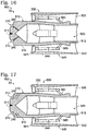
- fluid conduits 240 when present, may extend between gland 210 and a central cavity 520 that extends within poppet 500 and/or that is defined by elongate central core 510. As illustrated in Fig. 17 , fluid conduits 240, when present, may extend between gland 210 and outer core surface 514 of elongate central core 510. As illustrated in Fig. 18 , second body 200 may define a plurality of fluid conduits 240.
- Fig. 20 is a schematic cross-sectional view of a portion of another valve assembly 400 according to the present disclosure.
- Valve assembly 400 of Fig. 20 also may be referred to herein as a membrane valve assembly 400, as a check valve assembly 400, as a stacked disk check valve assembly 400, and/or as a membrane check valve assembly 400.
- Valve assembly 400 includes a valve body 405, a membrane disk 580, and a sealing structure 20.
- Valve body 405 defines a body-side sealing surface 416
- membrane disk 580 defines a disk-side sealing surface 586 that faces toward body-side sealing surface 416.
- valve assembly 400 of Fig. 20 is configured to transition between an open position, which is illustrated in Fig. 20 and in which the valve assembly permits a fluid flow 50 therethrough, and a closed position, in which the valve assembly restricts the fluid flow therethrough, and sealing structure 20 is configured to form a fluid seal between valve body 405 and membrane disk 580 when valve assembly 400 of Fig. 20 is in the closed position.
- the terms “adapted” and “configured” mean that the element, component, or other subject matter is designed and/or intended to perform a given function. Thus, the use of the terms “adapted” and “configured” should not be construed to mean that a given element, component, or other subject matter is simply “capable of” performing a given function but that the element, component, and/or other subject matter is specifically selected, created, implemented, utilized, programmed, and/or designed for the purpose of performing the function. It is also within the scope of the present disclosure that elements, components, and/or other recited subject matter that is recited as being adapted to perform a particular function may additionally or alternatively be described as being configured to perform that function, and vice versa. Similarly, subject matter that is recited as being configured to perform a particular function may additionally or alternatively be described as being operative to perform that function.
- the phrase "at least one,” in reference to a list of one or more entities should be understood to mean at least one entity selected from any one or more of the entity in the list of entities, but not necessarily including at least one of each and every entity specifically listed within the list of entities and not excluding any combinations of entities in the list of entities.
- This definition also allows that entities may optionally be present other than the entities specifically identified within the list of entities to which the phrase "at least one" refers, whether related, quasi-related, or unrelated to those entities specifically identified.
- At least one of A and B may refer, in one embodiment, to at least one, optionally including more than one, A, with no B present (and optionally including entities other than B); in another embodiment, to at least one, optionally including more than one, B, with no A present (and optionally including entities other than A); in yet another embodiment, to at least one, optionally including more than one, A, and at least one, optionally including more than one, B (and optionally including other entities).
- each of the expressions “at least one of A, B and C,” “at least one of A, B, or C,” “one or more of A, B, and C,” “one or more of A, B, or C” and “A, B, and/or C” may mean A alone, B alone, C alone, A and B together, A and C together, B and C together, A, B and C together, and optionally any of the above in combination with at least one other entity.
- a sealing structure comprising:
- the retention structure is at least one of:
- the retention structure includes a first retaining edge, which projects across a first side of the gland opening, and a second retaining edge, which projects across an opposed second side of the gland opening.
- the first retaining edge is continuous about a first circumference of a first edge that defines a first side of the gland opening, and further wherein the second retaining edge is continuous about a second circumference of a second edge that defines a second side of the gland opening.
- the gland opening defines an opening width, wherein the gland defines a maximum transverse cross-sectional extent as measured parallel to the second surface, and further wherein the opening width is less than the maximum transverse cross-sectional extent.
- the gland opening defines an opening width, and further wherein the opening width is at least substantially uniform along an edge that defines the gland opening.
- a transverse cross-sectional shape of the gland is at least one of:
- the gland includes a resilient sealing body-retaining region and a projecting region that projects away from the resilient sealing body-retaining region and into the second body.
- the projecting region is configured to facilitate deformation of a transverse cross-section of the gland based, at least in part, on at least one of:
- the second body includes a first material with a first coefficient of thermal expansion and a second material with a second coefficient of thermal expansion, which is different from the first coefficient of thermal expansion, and further wherein the gland is defined, or bordered, by both the first material and the second material.
- the second body further includes a fluid conduit that opens into the gland, wherein the sealing structure further includes at least one of:
- the sealing structure further includes an electrically conductive conduit extending within the second body and is in electrical communication with the gland.
- the sealing structure further includes a seal detection structure configured to detect the fluid seal between the first surface and the second surface.
- the seal detection structure includes at least a first electrically conductive surface, which is defined on the first body, and a second electrically conductive surface, which is defined on the second body, wherein the resilient sealing body is an electrically conductive resilient sealing body, and further wherein the seal detection structure is configured to detect electrical contact between the first electrically conductive surface and the second electrically conductive surface via the electrically conductive resilient sealing body.
- the second body further includes a magnetic material in magnetic communication with the gland, wherein the resilient sealing body is a magnetic resilient sealing body, and further wherein the sealing structure is configured to retain the resilient sealing body within the gland via a magnetic interaction between the magnetic material and the magnetic resilient sealing body.
- the second body further defines at least one slit, which is proximal the gland and extends from the second surface and into the second body.
- the resilient sealing body is an O-ring.
- a transverse cross-sectional shape of the resilient sealing body is at least one of:
- the second body is formed via an additive manufacturing process.
- the gland is a first gland that defines a first gland opening
- the resilient sealing body is a first resilient sealing body
- the sealing structure includes:
- the phrase, "for example,” the phrase, “as an example,” the abbreviation “e.g.,” the phrase “exempla gratia,” and/or simply the term “example,” when used with reference to one or more components, features, details, structures, embodiments, and/or methods according to the present disclosure, are intended to convey that the described component, feature, detail, structure, embodiment, and/or method is an illustrative, non-exclusive example of components, features, details, structures, embodiments, and/or methods according to the present disclosure.
Landscapes
- Engineering & Computer Science (AREA)
- General Engineering & Computer Science (AREA)
- Mechanical Engineering (AREA)
- Physics & Mathematics (AREA)
- Geometry (AREA)
- Sealing Devices (AREA)
- Gasket Seals (AREA)
Abstract
Description
- The present disclosure relates generally to sealing structures and to valve assemblies including the sealing structures.
- Sealing structures may be utilized to form a fluid seal between a first body and a second body. Some sealing structures utilize a resilient sealing body, such as an O-ring, to form the fluid seal between the first body and the second body. In such sealing structures, a gland, land, channel, and/or groove may be formed within the first body and/or within the second body, and the resilient sealing body may be positioned within the gland, thereby retaining the resilient sealing body at, or within, an interface region between the first body and the second body.
- In certain applications, such as valve assemblies, the sealing structure may be repeatedly transitioned between a closed position, in which the fluid seal is present, a neutral (i.e. zero-force) position, and/or an open position, in which the fluid seal is not present, and it may be desirable to retain the resilient sealing body within the gland regardless of the configuration of the sealing structure. It is known to utilize an adhesive and/or bonding agent to retain the resilient sealing body within the gland; however, adhesives may be unsuitable for some applications, may fail when the sealing structure is repeatedly transitioned between the closed position and the open position, and/or may fail when the sealing structure is subjected to extreme temperatures, to extreme temperature variation, and/or to certain fluids, such as solvents. Thus, there exists a need for improved sealing structures and/or for valve assemblies including the improved sealing structures.
- Sealing structures and valve assemblies including the sealing structures are disclosed herein. The sealing structures include a first body, which defines a first surface. The sealing structures also include a second body, which defines a second surface. The second body also defines a gland, which extends into the second body from the second surface and defines a gland opening on the second surface. The gland is free of both a tool entry point and a tool exit point. The second body further defines a retention structure projecting partially across the gland to at least partially define the gland opening. The sealing structure also includes a resilient sealing body that is positioned within the gland. The retention structure retains the resilient sealing body within the gland, and the resilient sealing body forms a fluid seal between the first body and the second body when the resilient sealing body is brought into pressing engagement with both the first surface and the gland.
- Some aspects of the present invention are described, by way of example only, with reference to the accompanying figures, in which:
-
Fig. 1 is a schematic cross-sectional view of examples of a sealing structure according to the present disclosure. -
Fig. 2 is a schematic top view of a second body of the sealing structure ofFig. 1 . -
Fig. 3 is a schematic cross-sectional view of a gland according to the present disclosure. -
Fig. 4 is a schematic cross-sectional view of a gland according to the present disclosure. -
Fig. 5 is a schematic cross-sectional view of a gland according to the present disclosure. -
Fig. 6 is a schematic cross-sectional view of a gland according to the present disclosure. -
Fig. 7 is a schematic cross-sectional view of a gland according to the present disclosure. -
Fig. 8 is a schematic cross-sectional view of a resilient sealing body that may be utilized with the sealing structures according to the present disclosure. -
Fig. 9 is a schematic cross-sectional view of a resilient sealing body that may be utilized with the sealing structures according to the present disclosure. -
Fig. 10 is a schematic cross-sectional view of a resilient sealing body that may be utilized with the sealing structures according to the present disclosure. -
Fig. 11 is a schematic cross-sectional view of a resilient sealing body that may be utilized with the sealing structures according to the present disclosure. -
Fig. 12 is a cutaway side view of a valve assembly, according to the present disclosure, in a closed position. -
Fig. 13 is a cutaway side view of a valve assembly, according to the present disclosure, in an open position. -
Fig. 14 is a schematic cross-sectional view of a poppet according to the present disclosure. -
Fig. 15 is a schematic cross-sectional view of a portion of a poppet according to the present disclosure. -
Fig. 16 is a schematic cross-sectional view of a poppet according to the present disclosure. -
Fig. 17 is a schematic cross-sectional view of a poppet according to the present disclosure. -
Fig. 18 is a schematic cross-sectional view of a poppet according to the present disclosure. -
Fig. 19 is a schematic cross-sectional view of a portion of a poppet according to the present disclosure. -
Fig. 20 is a schematic cross-sectional view of a portion of a membrane check valve assembly according to the present disclosure. -
Figs. 1-20 provide illustrative, non-exclusive examples of sealingstructures 20, ofvalve assemblies 400, and/or of portions ofvalve assemblies 400, according to the present disclosure. Elements that serve a similar, or at least substantially similar, purpose are labeled with like numbers in each ofFigs. 1-20 , and these elements may not be discussed in detail herein with reference to each ofFigs. 1-20 . Similarly, all elements may not be labeled in each ofFigs. 1-20 , but reference numerals associated therewith may be utilized herein for consistency. Elements, components, and/or features that are discussed herein with reference to one or more ofFigs. 1-20 may be included in and/or utilized with any ofFigs. 1-20 without departing from the scope of the present disclosure. - In general, elements that are likely to be included in a given (i.e., a particular) embodiment are illustrated in solid lines, while elements that are optional to a given embodiment are illustrated in dashed lines. However, elements that are shown in solid lines are not essential to all embodiments, and an element shown in solid lines may be omitted from a particular embodiment without departing from the scope of the present disclosure.
-
Fig. 1 is a schematic cross-sectional view of examples of a sealingstructure 20, according to the present disclosure, whileFig. 2 is a schematic top view of asecond body 200 of sealingstructure 20 ofFig. 1 .Sealing structures 20 may be utilized and/or may form a portion of avalve assembly 400, examples of which are disclosed herein. - As illustrated in
Fig. 1 , sealingstructure 20 may include afirst body 100, which defines afirst surface 102, and includes asecond body 200, which defines asecond surface 202 and aresilient sealing body 300.Second body 200 also defines agland 210 that extends intosecond body 200 fromsecond surface 202 and defines agland opening 212 on the second surface.Second body 200 further is operatively attached to and/or defines aretention structure 220 that projects at least partially acrossgland 210 and at least partially definesgland opening 212.Resilient sealing body 300 is positioned withingland 210 and retained withingland 210 byretention structure 220. In addition, and as illustrated inFig. 1 ,resilient sealing body 300 forms afluid seal 90 betweenfirst body 100 andsecond body 200 whenresilient sealing body 300 is brought into pressing contact, or engagement, with bothfirst surface 102 andgland 210. - During operation, or use, of sealing
structures 20 and/or of assemblies, such asvalve assembly 400, that include sealingstructures 20, sealingstructure 20 may be repeatedly, periodically, and/or irregularly cycled between a closed position and an open position. When in the closed position,resilient sealing body 300 may be positioned withingland 210 and may be compressed betweenfirst body 100 andsecond body 200 to form and/or definefluid seal 90. This closed position is illustrated inFig. 1 byfirst body 100, which is illustrated in dashed lines, pressing againstresilient sealing body 300. The closed position also is illustrated, inFig. 12 , for an example ofvalve assembly 400. When sealingstructure 20 is in the closed position,resilient sealing body 300 may be at least substantially surrounded byfirst body 100 andsecond body 200, thereby retainingresilient sealing body 300 withingland 210 and/or preventing separation ofresilient sealing body 300 fromfirst body 100 and/or fromsecond body 200. - In contrast, when sealing
structure 20 is in the open position and/or in a neutral position,resilient sealing body 300 may not be compressed betweenfirst body 100 andsecond body 200. The open position is illustrated inFig. 1 by the absence of optionalfirst body 100 and also is illustrated inFigs. 13 and20 for examples ofvalve assemblies 400 in whichfirst body 100 andsecond body 200 do not compressresilient sealing body 300 therebetween. Stated another way, and when sealingstructure 20 is in the open position,first body 100 may not be in physical contact withresilient sealing body 300 and/or a distance betweenfirst body 100 andsecond body 200 may be greater than a corresponding distance when sealingstructure 20 is in the closed position. As such,resilient sealing body 300 may protrude fromgland opening 212 and/or it may be possible forresilient sealing body 300 to move out ofgland 210 viagland opening 212. However, and as discussed,retention structure 220 retainsresilient sealing body 300 withingland 210 and/or prevents separation ofresilient sealing body 300 fromsecond body 200. - In contrast with sealing
structures 20 according to the present disclosure, conventional sealing structures that utilize a gland and a resilient sealing body, which is positioned within the gland, to form a fluid seal between two bodies generally are configured to be assembled to form a fluid seal and subsequently to maintain the fluid seal throughout an operational lifetime, or at least during normal operation of, the sealing structure. Stated another way, conventional sealing structures that utilize a gland and a resilient sealing body, which is positioned within the gland, to form a fluid seal generally are not configured to be repeatedly cycled between an open position and a closed position. Thus, a potential for the resilient sealing body to move out of the gland of the conventional sealing structure is quite low. Cyclic loading, thermal gradients, vibration loading, and/or other physical and/or chemical influences, such as instances where pre-loading or lock-nuts are not applied, also may be detrimental to the operation, or sealing ability, of such conventional sealing structures. - In contrast, sealing
structures 20 according to the present disclosure generally are configured for operation within assemblies, such asvalve assemblies 400, in which the sealing structure is repeatedly cycled between the open position and the closed position. In such an assembly, the resilient sealing body of conventional sealing structures may move out of the gland, thereby rendering the sealing assembly inoperable. However, in sealingassemblies 20, according to the present disclosure,retention structure 220 retains the resilient sealing body within the gland during this cycling. As an example, and as discussed in more detail herein, the resilient sealing body may be configured for a snap-fit within the gland. - The potential for the resilient sealing body of conventional sealing structures to move out of the gland is increased when the sealing assembly is thermally cycled, utilized in a hot environment, utilized in a lukewarm and/or ambient environment, utilized in a cold environment, and/or utilized in a cryogenic environment. However, sealing
structures 20 according to the present disclosure overcome this limitation via retention ofresilient sealing body 300 withingland 210 withretention structure 220. -
Retention structure 220 may include any suitable structure that may be adapted, configured, designed, sized, shaped, and/or constructed to project at least partially acrossgland 210, to at least partially definegland opening 212, to retainresilient sealing body 300 withingland 210, and/or to prevent separation ofresilient sealing body 300 fromsecond body 200.Retention structure 220 may have and/or define any suitable shape. As an example, and as illustrated inFig. 2 ,retention structure 220 may be symmetric, rotationally symmetric, longitudinally symmetric, and/or radially symmetric about acentral point 224 and/or off-center foci. Stated another way,retention structure 220 may be continuous along alength 216, along aperimeter 215, and/or along anedge 217 ofgland 210.Retention structure 220 also may be radially balanced. -
Second body 200 and/orretention structure 220 may be formed utilizing a manufacturing process, such as an additive manufacturing process and/or a casting process, that permits formation of auniform retention structure 220 and/or that permits formation of aretention structure 220 that does not include, or exhibit, tooling entry and/or exit points, as may be required in subtractive manufacturing processes. Such a configuration forretention structure 220 may provide astronger retention structure 220 and/or may provide astronger sealing structure 20 when compared to a retention structure that is not symmetrical and/or that exhibits tooling entry and/or exit points. - With reference to
Fig. 1 ,retention structure 220 may have and/or define a rounded edge 226, which also may be referred to herein as a rounded resilient sealing body-compressing edge 226. Rounded edge 226 may at least partially definegland opening 212, may contactresilient sealing body 300 whenresilient sealing body 300 is positioned withingland 210, and/or may press against, or compress,resilient sealing body 300 asresilient sealing body 300 is inserted into, or positioned within,gland 210.Resilient sealing body 300 may be compressed upon insertion intogland 210, and the presence of rounded edge 226 may decrease a potential for damage toresilient sealing body 300 whenresilient sealing body 300 is inserted withingland 210. The rounded edge may, in one instantiation, be entirely omitted, be comprised of a multitude of curves or a multitude of small, tangential surfaces, the latter for use with doublet-lattice modeling. - As illustrated in
Figs. 1-2 ,retention structure 220 may include afirst retaining edge 221 and asecond retaining edge 222. First retainingedge 221 may project from afirst side 213 ofgland opening 212, while second retainingedge 222 may project from asecond side 214 ofgland opening 212. In addition, first retainingedge 221 may be continuous about a first circumference offirst side 213. Similarly,second retaining edge 222 may be continuous about a second circumference ofsecond side 214. - As illustrated in
Fig. 1 , first retainingedge 221 and/or second retainingedge 222 may have and/or define anedge angle 228 relative tosecond surface 202 ofsecond body 200.Edge angle 228 may be selected based upon one or more design constraints of sealingstructure 20, ofresilient sealing body 300, and/or of a manufacturing process that is utilized to manufacture at leastsecond body 200 and may have any suitable value. As examples,edge angle 228 may be at least 10 degrees, at least 15 degrees, at least 20 degrees, at least 25 degrees, at least 30 degrees, at least 35 degrees, at least 37 degrees, at least 39 degrees, and/or at least 41 degrees. Additionally or alternatively,edge angle 228 may be at most 60 degrees, at most 55 degrees, at most 53 degrees, at most 51 degrees, at most 49 degrees, at most 47 degrees, and/or at most 45 degrees. -
Gland opening 212 may define anopening width 218.Opening width 218 may be measured in a direction that is parallel tosecond surface 202 and/or may be a minimum width of gland opening 212 as measured in the direction that is parallel tosecond surface 202.Opening width 218 may be uniform, at least substantially uniform, constant, and/or at least substantially constant alonglength 216 ofgland opening 212, as illustrated inFig. 2 . - Prior to being positioned within
gland 210,resilient sealing body 300 may define a maximum transversecross-sectional dimension 302.Opening width 218 may be less than maximum transversecross-sectional dimension 302. As examples,opening width 218 may be at most 95%, at most 90%, at most 85%, at most 80%, and/or at most 75% of maximum transversecross-sectional dimension 302 of the resilient sealing body. Additionally or alternatively,opening width 218 may be at least 45%, at least 48%, at least 50%, at least 53%, at least 55%, at least 60%, at least 65%, at least 70%, at least 75%, at least 80%, and/or at least 85% of maximum transversecross-sectional dimension 302 of the resilient sealing body. Stated another way, openingwidth 218 may be sized to regainresilient sealing body 300 withingland 210, may be sized to compressresilient sealing body 300 upon insertion ofresilient sealing body 300 intogland 210, and/or may be sized for the snap-fit between resilient sealingbody 300 andgland 210. Dimensions ofresilient sealing body 300 additionally or alternatively may be described, or quantified, by width, height, and radius (WHR) dimensions of the resilient sealing body. The width may correspond to maximum transversecross-sectional dimension 302. The height may be measured perpendicular to maximum transversecross-sectional dimension 302. The radius may be a distance betweencentral point 224 ofFig. 2 and the resilient sealing body. -
Gland 210 may define a maximum transversecross-sectional extent 219, which may be measured in a direction that is parallel tosecond surface 202, andopening width 218 may be less than maximumcross-sectional extent 219. As examples,opening width 218 may be at most 95%, at most 90%, at most 85%, at most 80%, and/or at most 75% of maximum transversecross-sectional extent 219. Additionally or alternatively,opening width 218 may be at least 50%, at least 55%, at least 60%, at least 65%, at least 70%, at least 75%, and/or at least 80% of maximum transversecross-sectional extent 219. -
Gland 210 may have and/or define any suitable shape that may at least partially contain and/or houseresilient sealing body 300 and/or that may permitresilient sealing body 300 to be positioned therein. As an example, and as illustrated inFig. 1 ,gland 210 may be square, at least partially square, rectangular, and/or at least substantially rectangular. As another example, and as illustrated inFig. 3 ,gland 210 may be circular, at least partially circular, arcuate, at least partially arcuate, and/or gibbous. As the Gibbous shape is more or less a partially immersed ellipse or circle, its industrial definition may chiefly center on its WHR (Width-Height-Radius) dimensions, where R may include two or more apsis radii. Whengland 210 is gibbous,gland 210 also may be referred to herein as a GOL or Gibbous O-ring Layering. - As yet another example, and as illustrated in
Fig. 4 ,gland 210 may be triangular and/or at least partially triangular. As another example, and as illustrated inFig. 5 ,gland 210 may be elliptical and/or at least partially elliptical. As yet another example, and as illustrated inFig. 6 ,gland 210 may be pentagonal, at least partially pentagonal, diamond-shaped, and/or at least partially diamond-shaped. As another example, and as illustrated inFigs. 1 ,4, and 6 ,gland 210 may be polygonal and/or at least partially polygonal. The gland may be stacked, double-gibbous, and/or triple or more, or some other variant, so as to contain two, or three or more O-rings in a single gland for blow-out redundancy. - Similar to
retention structure 220,gland 210 may be symmetric, rotationally symmetric, and/or radially symmetric aboutcentral point 224 ofFig. 2 . Additionally or alternatively,gland 210 may be free from, or may not exhibit, a tool entry point and/or a tool exit point. Additionally or alternatively, a transverse cross-sectional shape ofgland 210 may be constant, or at least substantially constant.Gland 210 also may be referred to herein as achannel 210, aland 210, and/or agroove 210. - As illustrated in dashed lines in
Fig. 1 and in solid lines inFig. 15 ,gland 210 may include a resilient sealing body-retainingregion 230 and one or more projectingregions 232 that project away from resilient sealing body-retainingregion 230 and/or intosecond body 200. Projectingregions 232 also may be referred to herein as sun-ray extensions 232. The sun-ray beam extensions may include fillets to avoid stress-centering and/or stress-fracture promulgation(s). - Projecting
regions 232, when present, may be adapted, configured, sized, and/or shaped to permit upstream-born fluid flow aroundresilient sealing body 300 whenresilient sealing body 300 is positioned withingland 210. Additionally or alternatively, projectingregions 232, when present, may be adapted, configured, sized, and/or shaped to facilitate heat transfer between resilient sealingbody 300 andsecond body 200. Additionally or alternatively, projectingregions 232 may be adapted, configured, sized, and/or shaped to facilitate deformation of the transverse cross-sectional shape ofgland 210 based, at least in part, on a temperature ofsecond body 200 and/or on a clamping force betweensecond body 200 andfirst body 100. - Projecting
regions 232 may include, be, and/or define a void, an open space, and/or a volume. Additionally or alternatively, and as illustrated in dashed lines inFig. 1 ,second body 200 may be formed from afirst material 234 with a first coefficient of thermal expansion and asecond material 236 with a second coefficient of thermal expansion that is different from the first coefficient of thermal expansion. Under these conditions,gland 210 may be defined and/or bordered by bothfirst material 234 andsecond material 236. Stated another way, projectingregions 232 may be filled withsecond material 236. Under these conditions, a location, shape, geometry, and/or coefficient of thermal expansion offirst material 234 andsecond material 236 may be selected to generate a directed, controlled, and/or desired deformation ofgland 210 with changes in the temperature ofsecond body 200. This is illustrated inFig. 7 , which illustrates, in solid lines, a shape ofgland 210 whensecond body 200 is at a first temperature and, in dashed lines, the shape ofgland 210 whensecond body 200 is at a second temperature that is different from the first temperature. - As illustrated in dashed lines in
Fig. 1 and in solid lines inFigs. 16-18 ,second body 200 may include and/or define afluid conduit 240 that opens intogland 210.Fluid conduit 240 also may be referred to herein as afluid distribution network 240 and/or as adendritic network 240.Fluid conduit 240 may be configured to provide and/or supply a backpressure togland 210, such as to control and/or regulate a separation pressure and/or a cracking pressure of sealingstructure 20. As an example, and as illustrated inFig. 1 , sealingstructure 20 may include and/or be in fluid communication with aback pressure source 242, such as viafluid conduit 240; and backpressure source 242 may be configured to provide and/or supply the back-pressure togland 210. The separation pressure may be defined as a pressure at whichfirst body 100 andsecond body 200 begin to move away from one another but at whichfluid seal 90 is maintained. The cracking pressure may be defined as a pressure at which fluid flow betweenfirst body 100 andresilient sealing body 300 is initiated. - Additionally or alternatively, sealing
structure 20 may include and/or be in fluid communication with alubricant source 244, andfluid conduit 240 may fluidly interconnectgland 210 andlubricant source 244. This may permitlubricant source 244 to provide a lubricant togland 210 viafluid conduit 240. The lubricant may improve the friction, wear, and/or other tribological characteristics of sealingstructure 20 when compared to conventional sealing structures that do not includelubricant source 244. - Additionally or alternatively, sealing
structure 20 may include and/or be in fluid communication with amotive fluid source 246, andfluid conduit 240 may fluidly interconnectgland 210 andmotive fluid source 246.Motive fluid source 246 may be configured to provide a motive force for sweeping motion ofresilient sealing body 300 withingland 210. - Additionally or alternatively, sealing
structure 20 may include and/or be in fluid communication with asensor 248, andfluid conduit 240 may fluidly interconnectgland 210 andsensor 248.Sensor 248 may be configured to detect a pressure, to detect a pressure withingland 210, and/or to detect a presence, or absence, offluid seal 90 betweenfirst surface 102 andsecond surface 202. - As also illustrated in dashed lines in
Fig. 1 , sealingstructure 20 additionally or alternatively may include an electricallyconductive conduit 250. Electricallyconductive conduit 250 may extend withinsecond body 200 and/or may extend in electrical communication withgland 210. Additionally or alternatively, electricallyconductive conduit 250 may electrically interconnectgland 210 with any suitable structure, such assensor 248. - As also illustrated in dashed lines in
Fig. 1 , sealingstructure 20 may include aseal detection structure 260.Seal detection structure 260 may be configured to detect the presence of, absence of, and/or chatter offluid seal 90 betweenfirst surface 102 andsecond surface 202. Additionally or alternatively,seal detection structure 260 may be configured to detect damage to the fluid seal, the potential for damage to the fluid seal, and/or seal rupturing impact between the first body and the second body. - The fluid seal may be detected in any suitable manner. As an example, seal
detection structure 260 may include a first electrically conductive surface 104, which is defined onfirst body 100 and/or forms at least a portion offirst surface 102, and a second electricallyconductive surface 204, which is defined onsecond body 200 and/or forms at least a portion ofsecond surface 202 and/or ofgland 210. Under these conditions, sealdetection structure 260 may be configured to detect electrical contact between first electrically conductive surface 104 and second electricallyconductive surface 204. The O-ring may be comprised in part or in whole of a conductive yet malleable material, such as gold, or other conductive material, such as silver or platinum. - It is within the scope of the present disclosure that
resilient sealing body 300 may include and/or be an electrically conductiveresilient sealing body 304. Under these conditions, electrically conductiveresilient sealing body 304 may be configured to form, or complete, the electrical contact between first electrically conductive surface 104 and second electricallyconductive surface 204. Stated another way,seal detection structure 260 may be configured to detect electrical contact between first electrically conductive surface 104 and second electricallyconductive surface 204 through and/or via electrically conductiveresilient sealing body 304. - As also illustrated in dashed lines in
Fig. 1 ,second body 200 may include a magnetic material 270 (e.g., neodymium) that is in magnetic communication with and/or partially definesgland 210. Under these conditions,resilient sealing body 300 may include and/or be a magneticresilient sealing body 306, and sealingstructure 20 further may retain magneticresilient sealing body 306 withingland 210 via a magnetic interaction betweenmagnetic material 270 and magneticresilient sealing body 306. - As illustrated in dashed lines in
Fig. 1 and in solid lines inFig. 19 ,second body 200 may include one ormore slits 280.Slits 280, when present, may be proximal to but spaced-apart fromgland 210 and may extend fromsecond surface 202 and intosecond body 200.Slits 280 may include asingle slit 280 or a pair, or more, ofopposed slits 280 on opposed sides ofgland 210.Slits 280 may be configured to facilitate deformation of the transverse cross-sectional shape ofgland 210, such as may be caused by the clamping force betweenfirst body 100 andsecond body 200. - It is within the scope of the present disclosure that sealing
structure 20 may include any suitable number ofglands 210 with corresponding resilient sealingbodies 300 positioned therein. As an example, sealingstructure 20 may include afirst gland 210, a corresponding firstresilient sealing body 300, and a correspondingfirst retention structure 220, as illustrated in solid lines inFig. 1 . In addition, sealingstructure 20 also may include asecond gland 210, a corresponding second resilient sealingbody 300, and a correspondingsecond retention structure 220, as illustrated in dashed lines inFig. 1. Fig. 1 illustratessecond gland 210 as being defined bysecond body 200 and/or by the same body as the body that definesfirst gland 210. However, it is within the scope of the present disclosure thatsecond body 200 may define onegland 210, such as the first gland, and thatfirst body 100 may define anothergland 210, such as the second gland. More glands and seals may be included for manned space-flight and/or exotic environments; as an example, seven seals of equal or varying geometries may be equally or non-equally spaced. - The presence of two or
more glands 210 withcorresponding retention structures 220 and resilient sealingbodies 300, in sealingstructure 20, may provide a number of benefits over sealingstructures 20 that include only asingle gland 210, a singleresilient sealing body 300, and asingle retention structure 220. As examples, the second resilient sealingbody 300 may be formed from a different material, may be configured to seal at a different pressure, and/or may be configured to seal at a different temperature relative to the firstresilient sealing body 300. As another example, the first and second resilient sealingbodies 300 may provide redundancy within sealingstructure 20. -
Resilient sealing body 300 may include, define, and/or have any suitable shape. As an example,resilient sealing body 300 may include, or be, an O-ring. As additional examples, a transverse cross-sectional shape ofresilient sealing body 300 may be round or at least partially round, as illustrated inFig. 1 , elliptical or at least partially elliptical, as illustrated inFig. 8 , square or at least partially square, as illustrated inFig. 9 , rectangular or at least partially rectangular, as illustrated inFig. 10 , and/or X-shaped or at least partially X-shaped, as illustrated inFig. 11 . As additional examples, the transverse cross-sectional shape ofresilient sealing body 300 may be arcuate, at least partially arcuate, polygonal, at least partially polygonal, pentagonal, at least partially pentagonal, triangular, and/or at least partially triangular. The cross-sectional shape of the sealing body may vary along a length of the body. The body may be Mobius-shaped. The body may be hollow, porous, and/or permeable. - It is within the scope of the present disclosure that
resilient sealing body 300 may include and/or be formed from any suitable material and/or materials. As examples,resilient sealing body 300 may include one or more of a polymer, a fluoropolymer, a rubber, a nitrile rubber, an ethylene polyene diene terpolymer, a fluorosilicone, a polytetrafluoroether, a polyurethane, a silicone, a fluoroelastomer, a metal, a steel, a stainless steel, copper, an electrically conductive material, copper, gold, an electrically insulating material, a carbon matrix composite (CMC), and/or an electrostatic discharge-resistant material. -
Resilient sealing body 300 also may be formed in any suitable manner. As an example,resilient sealing body 300 may be separately formed, such as via molding, and subsequently inserted intogland 210. As another example, resilient sealing body may be injected intogland 210 as a sealing liquid and subsequently cured therein. Under these conditions, a vacuum may be applied to an exposed surface of the sealing liquid, thereby causing the sealing liquid to at least partially project fromgland 210. Additionally or alternatively,gland 210 may be over-filled with the sealing liquid, thereby causing the sealing liquid to project fromgland 210. The sealing liquid, when utilized, may be cured in any suitable manner, such as via and/or utilizing heating, cooling, chemical curing, electromagnetic curing, and/or ultraviolet light curing. - As illustrated in
Fig. 1 ,resilient sealing body 300 may be configured to be compressed, or deformed by compression between,first body 100 andsecond body 200. With this in mind,resilient sealing body 300 may have and/or define any suitable hardness. As examples, a Shore hardness ofresilient sealing body 300 may be in the A50 to A55 range, in the A60 to A75 range, in the A80 to A90 range, and/or in the D51 to D55 range. -
First body 100 and/orsecond body 200 may be formed from, or may include, any suitable material and/or materials. As examples,first body 100 and/orsecond body 200 may include one or more of an aluminum alloy, Al10SiMg, an aluminum silicon magnesium alloy, a superalloy, a titanium alloy, Ti-6AI-4V, a titanium aluminum vanadium alloy, a polymer, a polyetherketoneketone, an acrylonitrile butadiene styrene, a poly(lactic) acid, Inconel™, stainless steel, a ferrous metal, an organic material, a naturally occurring material, a flexible material, an inflatable material, and/or bamboo. Whenfirst body 100 and/orsecond body 200 includes the inflatable material and/or the flexible material,first body 100 and/orsecond body 200 also may include a rigidity-enhancing structure configured to increase load rigidity, increase twisting rigidity, and/or increase hoop stress. As another example,first body 100 and/orsecond body 200 may be formed via and/or utilizing an additive manufacturing (industrially referred to as "AM") process, in some examples comprised of corrosion-resistant materials including but not limited to Inconel 626™ and/or Inconel 718™. -
First body 100 and/orsecond body 200 additionally or alternatively may include a functionally gradient material (FGM). The FGM, when present, may be selected to prevent, to suppress, and/or to reduce a potential for, arcing amongfirst body 100,second body 200, and/orresilient sealing body 300. The FGM may include a coating, such as anodization, and/or a bulk material that comprisesfirst body 100 and/orsecond body 200. The FGM may be positioned within any suitable portion offirst body 100 and/or ofsecond body 200. As examples, the FGM may define at least a portion ofgland 210, may define at least a portion offirst body 100 that contactsresilient sealing body 300, and/or may define at least a portion ofsecond body 200 that contactresilient sealing body 300. - As discussed,
retention structures 220 may be configured to retain resilient sealingbodies 300 withinglands 210. As such, sealingstructures 20 disclosed herein may not include, may not utilize, and/or may be free of an adhesive that extends between resilient sealingbody 300 andsecond body 200 and/or that retainsresilient sealing body 300 withingland 210. Stated another way,resilient sealing body 300 may not be retained withingland 210 by the adhesive. - In general, sealing
structures 20, which are disclosed herein, may be formed and/or manufactured utilizing any suitable manufacturing process, including but not limited to any suitable molding process, any suitable machining process, any suitable subtractive machining process, and/or any suitable additive machining process. However, the cross-sectional shape ofglands 210 may be most readily, or economically, formed via additive manufacturing processes. -
Fig. 12 is a cutaway side view of avalve assembly 400, according to the present disclosure, in a closed position, whileFig. 13 is a cutaway side view ofvalve assembly 400 in an open position.Valve assembly 400 includes avalve body 405 that may include and/or be formed from afirst body half 410 and asecond body half 420.Valve body 405 defines acentral cavity 402, aninlet 412 tocentral cavity 402, and anoutlet 422 fromcentral cavity 402.Valve body 405 also defines a body-side sealing surface 416, which isproximate inlet 412 and at least partially defines, or is located within,central cavity 402.Valve body 405 further defines aspring seat 426, which isproximate outlet 422 and at least partially defines, or is located within,central cavity 402. -
Valve assembly 400 further includes aspring 490, which is operatively engaged withspring seat 426, and apoppet 500, which defines a poppet-side sealing surface 516. The coil spring may be substituted for a leaf-spring, a pneumatic piston, or another suitable biasing structure.Poppet 500 is oriented withincentral cavity 402 such that poppet-side sealing surface 516 is proximate body-side sealing surface 416, andspring 490 is oriented withincentral cavity 402 such thatspring 490 presses againstpoppet 500 and urges poppet-side sealing surface 516 into sealing engagement with body-side sealing surface 416. -
Valve assembly 400 further includes a sealingstructure 20, which is configured to facilitate sealing engagement between poppet-side sealing surface 516 and body-side sealing surface 416.Sealing structure 20 may include any suitable structure, function, and/or feature of any sealingstructure 20 of any ofFigs. 1-11 . As an example,valve body 405 and/orfirst body half 410 thereof may include, be, and/or be defined by one offirst body 100 ofFig. 1 andsecond body 200 ofFig. 1 , whilepoppet 500 may include, be, and/or be defined by the other offirst body 100 ofFig. 1 andsecond body 200 ofFig. 1 . - As a more specific example, and as illustrated in
Figs. 12-13 ,valve body 405 may include, be, and/or be defined byfirst body 100 ofFigs. 1-2 , whilepoppet 500 may include, be, and/or be defined bysecond body 200 ofFig. 1 . Under these conditions,poppet 500 may define agland 210, and aresilient sealing body 300 may be positioned within the gland.Valve assemblies 400 that include sealingstructures 20, according to the present disclosure, may experience less tribologically induced wear when compared to conventional valve assemblies, which do not includeresilient sealing body 300. This decrease in wear may be due toresilient sealing body 300 absorbing a portion of the energy that is dissipated upon closing of the valve assembly and/or upon physical engagement betweenvalve body 405 andpoppet 500. -
Valve assembly 400 also may be referred to herein as and/or may be acheck valve 400, acheck valve assembly 400, and/or apoppet check valve 400. During operation ofvalve assembly 400,spring 490 may biaspoppet 500 toward the closed position that is illustrated inFig. 12 . However, application of greater than a threshold pressure differential betweeninlet 412 andoutlet 422 may causevalve assembly 400 to transition to the open position that is illustrated inFig. 13 . Subsequently, the pressure differential may be decreased to less than the threshold pressure differential, andvalve assembly 400 may transition back to the closed position ofFig. 12 . -
Figs. 14-19 provide additional examples ofpoppets 500 that may be included in and/or utilized withvalve assemblies 400, according to the present disclosure. Thesepoppets 500 include various configurations forgland 210 and are discussed generally above. - As illustrated collectively by
Figs. 14-19 ,poppets 500 may include an elongatecentral core 510 having a firstcore end 511, a secondcore end 512, and anouter core surface 514 that extends between firstcore end 511 and secondcore end 512. Firstcore end 511 may define, or be, poppet-side sealing surface 516. As also illustrated collectively byFigs. 14-19 ,poppets 500 also may include an elongateouter skit 540 having afirst skirt end 541, asecond skirt end 542, anouter skirt surface 544 that extends betweenfirst skirt end 541 andsecond skirt end 542, and aninner skirt surface 552 that extends betweenfirst skirt end 541 andsecond skirt end 542. As illustrated inFigs. 14 and16-18 ,poppet 500 further may include at least oneguide vane 560, which extends between outercore surface 514 andinner skirt surface 552. - As illustrated in
Fig. 16 ,fluid conduits 240, when present, may extend betweengland 210 and acentral cavity 520 that extends withinpoppet 500 and/or that is defined by elongatecentral core 510. As illustrated inFig. 17 ,fluid conduits 240, when present, may extend betweengland 210 andouter core surface 514 of elongatecentral core 510. As illustrated inFig. 18 ,second body 200 may define a plurality offluid conduits 240. -
Fig. 20 is a schematic cross-sectional view of a portion of anothervalve assembly 400 according to the present disclosure.Valve assembly 400 ofFig. 20 also may be referred to herein as amembrane valve assembly 400, as acheck valve assembly 400, as a stacked diskcheck valve assembly 400, and/or as a membranecheck valve assembly 400.Valve assembly 400 includes avalve body 405, amembrane disk 580, and a sealingstructure 20.Valve body 405 defines a body-side sealing surface 416, andmembrane disk 580 defines a disk-side sealing surface 586 that faces toward body-side sealing surface 416. - Similar to
valve assembly 400 ofFigs. 12-19 ,valve assembly 400 ofFig. 20 is configured to transition between an open position, which is illustrated inFig. 20 and in which the valve assembly permits afluid flow 50 therethrough, and a closed position, in which the valve assembly restricts the fluid flow therethrough, and sealingstructure 20 is configured to form a fluid seal betweenvalve body 405 andmembrane disk 580 whenvalve assembly 400 ofFig. 20 is in the closed position. - Illustrative, non-exclusive examples of inventive subject matter according to the present disclosure are described in the following enumerated paragraphs:
- A1. A sealing structure, comprising:
- a first body defining a first surface;
- a second body defining:
- (i) a second surface;
- (ii) a gland extending into the second body from the second surface and defining a gland opening on the second surface; and
- (iii) a retention structure projecting partially across the gland to at least partially define the gland opening; and
- a resilient sealing body positioned within the gland, wherein:
- (i) the retention structure retains the resilient sealing body within the gland; and
- (ii) the resilient sealing body forms a fluid seal between the first body and the second body when the resilient sealing body is brought into pressing engagement with both the first surface and the gland.
- A2. The sealing structure of paragraph A1, wherein at least one of:
- (i) the retention structure is rotationally, or radially, symmetric about a central point; and
- (ii) the retention structure may be radially balanced about a central point.
- A3. The sealing structure of any of paragraphs A1-A2, wherein the retention structure is continuous along a length, along a perimeter, or along an edge of the gland.
- A4. The sealing structure of any of paragraphs A1-A3, wherein the retention structure defines a rounded resilient sealing body-compressing edge that at least partially defines the gland opening.
- A5. The sealing structure of any of paragraphs A1-A4, wherein the retention structure includes a first retaining edge, which projects across a first side of the gland opening, and a second retaining edge, which projects across an opposed second side of the gland opening.
- A6. The sealing structure of paragraph A5, wherein the first retaining edge and the second retaining edge define an edge angle relative to the second surface, optionally wherein the edge angle is at least one of:
- (i) at least 10 degrees, at least 15 degrees, at least 20 degrees, at least 25 degrees, at least 30 degrees, at least 35 degrees, at least 37 degrees, at least 39 degrees, or at least 41 degrees; and
- (ii) at most 60 degrees, at most 55 degrees, at most 53 degrees, at most 51 degrees, at most 49 degrees, at most 47 degrees, or at most 45 degrees.
- A7. The sealing structure of any of paragraphs A5-A6, wherein the first retaining edge is continuous about a first circumference of a first edge that defines a first side of the gland opening.
- A8. The sealing structure of any of paragraphs A5-A7, wherein the second retaining edge is continuous about a second circumference of a second edge that defines a second side of the gland opening.
- A9. The sealing structure of any of paragraphs A1-A8, wherein the gland opening defines an opening width, wherein, prior to being positioned within the gland, the resilient sealing body defines a maximum transverse cross-sectional dimension, and further wherein the opening width is less than the maximum transverse cross-sectional dimension of the resilient sealing body.
- A10. The sealing structure of paragraph A9, wherein the opening width is sized to retain the resilient sealing body within the gland.
- A11. The sealing structure of any of paragraphs A9-A10, wherein the opening width is at least one of:
- (i) at most 95%, at most 90%, at most 85%, at most 80%, or at most 75% of the maximum transverse cross-sectional dimension of the resilient sealing body; and
- (ii) at least 45%, at least 48%, at least 50%, at least 53%, at least 55%, at least 60%, at least 65%, at least 70%, at least 75%, at least 80%, or at least 85% of the maximum transverse cross-sectional dimension of the resilient sealing body.
- A12. The sealing structure of any of paragraphs A1-A11, wherein the gland opening defines an/the opening width, wherein the gland defines a maximum transverse cross-sectional extent as measured parallel to the second surface, and further wherein the opening width is less than the maximum transverse cross-sectional extent.
- A13. The sealing structure of paragraph A12, wherein the opening width is at least one of:
- (i) at most 95%, at most 90%, at most 85%, at most 80%, or at most 75% of the maximum transverse cross-sectional extent; and
- (ii) at least 50%, at least 55%, at least 60%, at least 65%, at least 70%, at least 75%, or at least 80% of the maximum transverse cross-sectional extent.
- A14. The sealing structure of any of paragraphs A1-A13, wherein the gland opening defines an/the opening width, and further wherein the opening width is uniform, or at least substantially uniform, along a length of the gland opening, along a perimeter of the gland opening, or along an edge that defines the gland opening.
- A15. The sealing structure of any of paragraphs A1-A14, wherein the gland is rotationally, or radially, symmetric about a/the central point.
- A16. The sealing structure of any of paragraphs A1-A15, wherein a transverse cross-sectional shape of the gland is at least one of:
- (i) at least partially circular;
- (ii) gibbous;
- (iii) at least partially square;
- (iv) at least partially triangular;
- (v) at least partially elliptical;
- (vi) at least partially pentagonal;
- (vii) at least partially diamond-shaped;
- (viii) at least partially arcuate;
- (ix) at least partially polygonal;
- (x) at least partially pentagonal; and
- (xi) at least partially triangular.
- A17. The sealing structure of any of paragraphs A1-A16, wherein the gland is free of both a tool entry point and a tool exit point.
- A18. The sealing structure of any of paragraphs A1-A17, wherein the gland includes a resilient sealing body-retaining region and a projecting region that projects away from the resilient sealing body-retaining region and into the second body.
- A19. The sealing structure of paragraph A18, wherein the projecting region is configured to permit fluid flow around the resilient sealing body.
- A20. The sealing structure of any of paragraphs A18-A19, wherein the projecting region is configured to facilitate heat transfer between the resilient sealing body and the second body.
- A21. The sealing structure of any of paragraphs A18-A20, wherein the projecting region is configured to facilitate deformation of a/the transverse cross-section of the gland based, at least in part, on at least one of:
- (i) a temperature of the second body; and
- (ii) a clamping force between the first body and the second body.
- A22. The sealing structure of any of paragraphs A1-A21, wherein the second body includes a first material with a first coefficient of thermal expansion and a second material with a second coefficient of thermal expansion, which is different from the first coefficient of thermal expansion, and further wherein the gland is defined, or bordered, by both the first material and the second material.
- A23. The sealing structure of paragraph A22, wherein a location and a coefficient of thermal expansion of each of the first material and the second material are selected to generate directed deformation of the gland with changes in a/the temperature of the second body.
- A24. The sealing structure of any of paragraphs A1-A23, wherein the second body further includes a fluid conduit that opens into the gland.
- A25. The sealing structure of paragraph A24, wherein the sealing structure further includes a back pressure source, and further wherein the fluid conduit fluidly interconnects the gland with the back pressure source, which is configured to provide a back pressure to the resilient sealing body to selectively regulate a separation pressure, or a cracking pressure, of the sealing structure.
- A26. The sealing structure of any of paragraphs A24-A25, wherein the sealing structure further includes a lubricant source, and further wherein the fluid conduit fluidly interconnects the gland with the lubricant source, which is configured to provide a lubricant to the gland.
- A27. The sealing structure of any of paragraphs A24-A26, wherein the sealing structure further includes a motive fluid source, and further wherein the fluid conduit fluidly interconnects the gland with the motive fluid source, which is configured to provide a motive force for sweeping motion of the resilient sealing body within the gland.
- A28. The sealing structure of any of paragraphs A24-A27, wherein the sealing structure further includes a sensor, and further wherein the fluid conduit fluidly interconnects the gland with the sensor.
- A29. The sealing structure of paragraph A28, wherein the sensor is configured to at least one of:
- (i) detect a pressure within the gland;
- (ii) detect a pressure;
- (iii) detect the fluid seal between the first surface and the second surface; and
- (iv) detect an absence of the fluid seal between the first surface and the second surface.
- A30. The sealing structure of any of paragraphs A1-A29, wherein the sealing structure further includes an electrically conductive conduit extending within the second body and in electrical communication with the gland.
- A31. The sealing structure of any of paragraphs A1-A30, wherein the sealing structure further includes a seal detection structure configured to detect the fluid seal between the first surface and the second surface.
- A32. The sealing structure of paragraph A31, wherein the seal detection structure includes at least a first electrically conductive surface, which is defined on the first body, and a second electrically conductive surface, which is defined on the second body, and further wherein the seal detection structure is configured to detect electrical contact between the first electrically conductive surface and the second electrically conductive surface.
- A33. The sealing structure of paragraph A32, wherein the resilient sealing body is an electrically conductive resilient sealing body, and further wherein the seal detection structure is configured to detect electrical contact between the first electrically conductive surface and the second electrically conductive surface via the electrically conductive resilient sealing body.
- A34. The sealing structure of any of paragraphs A31-A33, wherein the seal detection structure is configured to detect at least one of:
- (i) a presence of the fluid seal;
- (ii) an absence of the fluid seal;
- (iii) chatter of the fluid seal; and
- (iv) seal rupturing impact between the first body and the second body.
- A35. The sealing structure of any of paragraphs A1-A34, wherein the second body further includes a magnetic material in magnetic communication with the gland, wherein the resilient sealing body is a magnetic resilient sealing body, and further wherein the sealing structure is configured to retain the resilient sealing body within the gland via a magnetic interaction between the magnetic material and the magnetic resilient sealing body.
- A36. The sealing structure of any of paragraphs A1-A35, wherein the second body further defines at least one slit, which is proximal the gland and extends from the second surface and into the second body.
- A37. The sealing structure of paragraph A36, wherein the at least one slit include a pair of opposed slits on opposed sides of the gland.
- A38. The sealing structure of any of paragraphs A1-A37, wherein the at least one slit is configured to facilitate deformation of the gland.
- A39. The sealing structure of any of paragraphs A1-A38, wherein the resilient sealing body includes, or is, an O-ring.
- A40. The sealing structure of any of paragraphs A1-A39, wherein a transverse cross-sectional shape of the resilient sealing body is at least one of:
- (i) round;
- (ii) at least partially round;
- (iii) elliptical;
- (iv) at least partially elliptical;
- (v) square;
- (vi) at least partially square;
- (vii) rectangular;
- (viii) at least partially rectangular;
- (ix) X-shaped;
- (x) at least partially X-shaped;
- (xi) arcuate;
- (xii) at least partially arcuate;
- (xiii) polygonal;
- (xiv) at least partially polygonal;
- (xv) hollow;
- (xvi) at least partially hollow;
- (xvii) porous;
- (xviii) at least partially porous;
- (xix) pentagonal;
- (xx) at least partially pentagonal;
- (xxi) triangular; and
- (xxii) at least partially triangular.
- A41. The sealing structure of any of paragraphs A1-A40, wherein the resilient sealing body is formed from at least one of:
- (i) a polymer;
- (ii) a fluoropolymer;
- (iii) a rubber;
- (iv) a nitrile rubber;
- (v) an ethylene polyene diene terpolymer;
- (vi) a fluorosilicone;
- (vii) a polytetrafluoroethylene;
- (viii) a polyurethane;
- (ix) a silicone;
- (x) a fluoroelastomer;
- (xi) a metal;
- (xii) a stainless steel;
- (xiii) copper;
- (xiv) an electrically conductive material;
- (xv) an electrically insulating material;
- (xvi) an electrostatic discharge-resistant material,
- (xvii) a Carbon Matrix Composite; and
- (xviii) gold.
- A42. The sealing structure of any of paragraphs A1-A41, wherein the resilient sealing body has a Shore hardness of at least one of:
- (i) A50 to A55;
- (ii) A60 to A75;
- (iii) A80 to A90; and
- (iv) D51 to D55.
- A43. The sealing structure of any of paragraphs A1-A42, wherein the sealing structure is free of an adhesive.
- A44. The sealing structure of any of paragraphs A1-A43, wherein the resilient sealing body is not retained within the gland by an/the adhesive.
- A45. The sealing structure of any of paragraphs A1-A44, wherein at least one, and optionally both, of the first body and the second body is formed from at least one of:
- (i) an aluminum alloy;
- (ii) an aluminum silicon magnesium alloy;
- (iii) a superalloy;
- (iv) a titanium alloy;
- (v) a titanium aluminum vanadium alloy;
- (vi) a polymer;
- (vii) a polyetherketoneketone;
- (viii) an acrylonitrile butadiene styrene;
- (ix) a poly(lactic) acid;
- (x) Inconel™;
- (xi) a ferrous metal;
- (xii) stainless steel;
- (xiii) an organic material;
- (xiv) a naturally occurring material;
- (xv) a flexible material;
- (xvi) an inflatable material; and
- (xvii) bamboo.
- A46. The sealing structure of any of paragraphs A1-A45, wherein the second body is formed utilizing at least one of an additive manufacturing technique and a casting technique.
- A47. The sealing structure of any of paragraphs A1-A46, wherein the gland is a first gland that defines a first gland opening, wherein the resilient sealing body is a first resilient sealing body, and further wherein the sealing structure includes:
- a second gland; and
- a second resilient sealing body positioned within the second gland.
- A48. The sealing structure of paragraph A47, wherein the second gland at least one of:
- (i) is defined by the first body; and
- (ii) is defined by the second body.
- A49. The sealing structure of any of paragraphs A47-A48, wherein the retention structure is a first retention structure, and further wherein the sealing structure includes a second retention structure that at least partially defines the second gland.
- A50. The sealing structure of paragraph A49, wherein the second retention structure includes any suitable structure of the retention structure of any of paragraphs A1-A46.
- A51. The sealing structure of any of paragraphs A49-A50, wherein the second gland includes any suitable structure of the gland of any of paragraphs A1-A46.
- A52. The sealing structure of any of paragraphs A49-A51, wherein the second resilient sealing body includes any suitable structure of the resilient sealing body of any of paragraphs A1-A46.
- B1. A check valve assembly, comprising:
- a valve body defining:
- (i) a central cavity;
- (ii) an inlet to the central cavity;
- (iii) an outlet from the central cavity;
- (iv) a body-side sealing surface within the central cavity and proximate the inlet; and
- (v) a spring seat within the central cavity and proximate the outlet;
- a spring operatively engaged, or mated, with the spring seat; and
- a poppet defining a poppet-side sealing surface, wherein:
- (i) the poppet is oriented, within the central cavity, such that the poppet-side sealing surface is proximate the body-side sealing surface;
- (ii) the spring is oriented, within the central cavity, to press against the poppet and to urge the poppet-side sealing surface into sealing engagement with the body-side sealing surface;
- (iii) the valve body is defined by one of the first body and the second body of any of paragraphs A1-A52; and
- (iv) the poppet is defined by the other of the first body and the second body of any of paragraphs A1-A52.
- a valve body defining:
- B2. The valve assembly of paragraph B1, wherein the poppet includes an elongate central core having a first core end, a second core end, and an outer core surface extending between the first core end and the second core end, wherein the first core end defines the poppet-side sealing surface, optionally which is configured to form a fluid seal with the body-side sealing surface.
- B3. The valve assembly of paragraph B2, wherein the poppet further includes an elongate outer skirt having a first skirt end, a second skirt end, an outer skirt surface, and an inner skirt surface, wherein the outer skirt surface and the inner skirt surface extend between the first skirt end and the second skirt end.
- B4. The valve assembly of paragraph B3, wherein the poppet further includes at least one guide vane radially extending between the outer core surface and the inner skirt surface.
- C1. A stacked disk check valve assembly, comprising:
- a valve body defined by one of the first body and the second body of any of paragraphs A1-A52; and
- a membrane disk defined by the other of the first body and the second body of any of paragraphs A1-A52.
- As used herein, the terms "selective" and "selectively," when modifying an action, movement, configuration, or other activity of one or more components or characteristics of an apparatus, mean that the specific action, movement, configuration, or other activity is a direct or indirect result of user manipulation and/or influence of an aspect of, or one or more components of, the apparatus.
- As used herein, the terms "adapted" and "configured" mean that the element, component, or other subject matter is designed and/or intended to perform a given function. Thus, the use of the terms "adapted" and "configured" should not be construed to mean that a given element, component, or other subject matter is simply "capable of" performing a given function but that the element, component, and/or other subject matter is specifically selected, created, implemented, utilized, programmed, and/or designed for the purpose of performing the function. It is also within the scope of the present disclosure that elements, components, and/or other recited subject matter that is recited as being adapted to perform a particular function may additionally or alternatively be described as being configured to perform that function, and vice versa. Similarly, subject matter that is recited as being configured to perform a particular function may additionally or alternatively be described as being operative to perform that function.
- As used herein, the phrase "at least one," in reference to a list of one or more entities should be understood to mean at least one entity selected from any one or more of the entity in the list of entities, but not necessarily including at least one of each and every entity specifically listed within the list of entities and not excluding any combinations of entities in the list of entities. This definition also allows that entities may optionally be present other than the entities specifically identified within the list of entities to which the phrase "at least one" refers, whether related, quasi-related, or unrelated to those entities specifically identified. Thus, as a non-limiting example, "at least one of A and B" (or, equivalently, "at least one of A or B," or, equivalently "at least one of A and/or B") may refer, in one embodiment, to at least one, optionally including more than one, A, with no B present (and optionally including entities other than B); in another embodiment, to at least one, optionally including more than one, B, with no A present (and optionally including entities other than A); in yet another embodiment, to at least one, optionally including more than one, A, and at least one, optionally including more than one, B (and optionally including other entities). In other words, the phrases "at least one," "one or more," and "and/or" are open-ended expressions that are both conjunctive and disjunctive in operation. For example, each of the expressions "at least one of A, B and C," "at least one of A, B, or C," "one or more of A, B, and C," "one or more of A, B, or C" and "A, B, and/or C" may mean A alone, B alone, C alone, A and B together, A and C together, B and C together, A, B and C together, and optionally any of the above in combination with at least one other entity.
- The various disclosed elements of apparatuses and steps of methods disclosed herein are not required to all apparatuses and methods according to the present disclosure, and the present disclosure includes all novel and non-obvious combinations and subcombinations of the various elements and steps disclosed herein. Moreover, one or more of the various elements and steps disclosed herein may define independent inventive subject matter that is separate and apart from the whole of a disclosed apparatus or method. Accordingly, such inventive subject matter is not required to be associated with the specific apparatuses and methods that are expressly disclosed herein, and such inventive subject matter may find utility in apparatuses and/or methods that are not expressly disclosed herein.
- Additional embodiments and features of the present disclosure are presented below without limitation. Features of each of these embodiments may be combined with one or more other embodiments from elsewhere in this disclosure, in any suitable manner.
- According to one aspect, there is provided a sealing structure, comprising:
- a first body defining a first surface;
- a second body defining:
- (i) a second surface;
- (ii) a gland extending into the second body from the second surface and defining a gland opening on the second surface, wherein the gland is free of both a tool entry point and a tool exit point; and
- (iii) a retention structure projecting partially across the gland to at least partially define the gland opening; and
- a resilient sealing body positioned within the gland, wherein:
- (i) the retention structure retains the resilient sealing body within the gland; and
- (ii) the resilient sealing body forms a fluid seal between the first body and the second body when the resilient sealing body is brought into pressing engagement with both the first surface and the gland.
- Optionally, the retention structure is at least one of:
- (i) rotationally symmetric about a central point; and
- (ii) continuous along an edge of the gland.
- Optionally, the retention structure includes a first retaining edge, which projects across a first side of the gland opening, and a second retaining edge, which projects across an opposed second side of the gland opening.
- Optionally, the first retaining edge is continuous about a first circumference of a first edge that defines a first side of the gland opening, and further wherein the second retaining edge is continuous about a second circumference of a second edge that defines a second side of the gland opening.
- Optionally, the gland opening defines an opening width, wherein the gland defines a maximum transverse cross-sectional extent as measured parallel to the second surface, and further wherein the opening width is less than the maximum transverse cross-sectional extent.
- Optionally, the gland opening defines an opening width, and further wherein the opening width is at least substantially uniform along an edge that defines the gland opening.
- Optionally, a transverse cross-sectional shape of the gland is at least one of:
- (i) at least partially circular;
- (ii) gibbous;
- (iii) at least partially square;
- (iv) at least partially triangular;
- (v) at least partially elliptical;
- (vi) at least partially pentagonal;
- (vii) at least partially diamond-shaped;
- (viii) at least partially arcuate; and
- (ix) at least partially polygonal.
- Optionally, the gland includes a resilient sealing body-retaining region and a projecting region that projects away from the resilient sealing body-retaining region and into the second body.
- Optionally, the projecting region is configured to facilitate deformation of a transverse cross-section of the gland based, at least in part, on at least one of:
- (i) a temperature of the second body; and
- (ii) a clamping force between the first body and the second body.
- Optionally, the second body includes a first material with a first coefficient of thermal expansion and a second material with a second coefficient of thermal expansion, which is different from the first coefficient of thermal expansion, and further wherein the gland is defined, or bordered, by both the first material and the second material.
- Optionally, the second body further includes a fluid conduit that opens into the gland, wherein the sealing structure further includes at least one of:
- (i) a back pressure source, wherein the fluid conduit fluidly interconnects the gland with the back pressure source, which is configured to provide a back pressure to the resilient sealing body to selectively regulate a cracking pressure of the sealing structure;
- (ii) a lubricant source, wherein the fluid conduit fluidly interconnects the gland with the lubricant source, which is configured to provide a lubricant to the gland;
- (iii) a motive fluid source, wherein the fluid conduit fluidly interconnects the gland with the motive fluid source, which is configured to provide a motive force for sweeping motion of the resilient sealing body within the gland;
- (iv) a sensor, wherein the fluid conduit fluidly interconnects the gland with the sensor.
- Optionally, the sealing structure further includes an electrically conductive conduit extending within the second body and is in electrical communication with the gland.
- Optionally, the sealing structure further includes a seal detection structure configured to detect the fluid seal between the first surface and the second surface.
- Optionally, the seal detection structure includes at least a first electrically conductive surface, which is defined on the first body, and a second electrically conductive surface, which is defined on the second body, wherein the resilient sealing body is an electrically conductive resilient sealing body, and further wherein the seal detection structure is configured to detect electrical contact between the first electrically conductive surface and the second electrically conductive surface via the electrically conductive resilient sealing body.
- Optionally, the second body further includes a magnetic material in magnetic communication with the gland, wherein the resilient sealing body is a magnetic resilient sealing body, and further wherein the sealing structure is configured to retain the resilient sealing body within the gland via a magnetic interaction between the magnetic material and the magnetic resilient sealing body.
- Optionally, the second body further defines at least one slit, which is proximal the gland and extends from the second surface and into the second body.
- Optionally, the resilient sealing body is an O-ring.
- Optionally, a transverse cross-sectional shape of the resilient sealing body is at least one of:
- (i) round;
- (ii) at least partially round;
- (iii) elliptical;
- (iv) at least partially elliptical;
- (v) square;
- (vi) at least partially square;
- (vii) rectangular;
- (viii) at least partially rectangular;
- (ix) X-shaped;
- (x) at least partially X-shaped;
- (xi) arcuate;
- (xii) at least partially arcuate;
- (xiii) polygonal; and
- (xiv) at least partially polygonal.
- Optionally, the second body is formed via an additive manufacturing process.
- Optionally, the gland is a first gland that defines a first gland opening, wherein the resilient sealing body is a first resilient sealing body, and further wherein the sealing structure includes:
- a second gland; and
- a second resilient sealing body positioned within the second gland.
- As used herein, the phrase, "for example," the phrase, "as an example," the abbreviation "e.g.," the phrase "exempla gratia," and/or simply the term "example," when used with reference to one or more components, features, details, structures, embodiments, and/or methods according to the present disclosure, are intended to convey that the described component, feature, detail, structure, embodiment, and/or method is an illustrative, non-exclusive example of components, features, details, structures, embodiments, and/or methods according to the present disclosure. Thus, the described component, feature, detail, pattern, structure, embodiment, and/or method is not intended to be limiting, required, or exclusive/exhaustive; and other components, features, details, structures, embodiments, and/or methods, including structurally and/or functionally similar and/or equivalent components, features, details, structures, embodiments, and/or methods, are also within the scope of the present disclosure.
Claims (15)
- A sealing structure (20), comprising:a first body (100) defining a first surface (102);a second body (200) defining:(i) a second surface (202);(ii) a gland (210) extending into the second body from the second surface and defining a gland opening (212) on the second surface, wherein the gland is free of both a tool entry point and a tool exit point; and(iii) a retention structure (220) projecting partially across the gland to at least partially define the gland opening; anda resilient sealing body (300) positioned within the gland, wherein:(i) the retention structure retains the resilient sealing body within the gland; and(ii) the resilient sealing body forms a fluid seal between the first body and the second body when the resilient sealing body is brought into pressing engagement with both the first surface and the gland.
- The sealing structure (20) of claim 1, wherein the retention structure (220) at least one of:(i) is rotationally symmetric about a central point (224); and(ii) is continuous along an edge (217) of the gland (210).
- The sealing structure (20) of any of claims 1-2, wherein the retention structure (220) includes a first retaining edge (221), which projects across a first side (213) of the gland opening (212), and a second retaining edge (222), which projects across an opposed second side (214) of the gland opening.
- The sealing structure (20) of claim 3, wherein the first retaining edge (221) is continuous about a first circumference of a first edge that defines a first side (213) of the gland opening (212), and further wherein the second retaining edge (222) is continuous about a second circumference of a second edge that defines a second side of the gland opening.
- The sealing structure (20) of any of claims 1-4, wherein the gland opening (212) defines an opening width (218), wherein the gland defines a maximum transverse cross-sectional extent (219) as measured parallel to the second surface (202), and further wherein the opening width is less than the maximum transverse cross-sectional extent.
- The sealing structure (20) of any of claims 1-5, wherein the gland (210) includes a resilient sealing body-retaining region (230) and a projecting region (232) that projects away from the resilient sealing body-retaining region and into the second body (200).
- The sealing structure (20) of claim 6, wherein the projecting region (232) is configured to facilitate deformation of a transverse cross-section of the gland (210) based, at least in part, on at least one of:(i) a temperature of the second body (200); and(ii) a clamping force between the first body (100) and the second body.
- The sealing structure (20) of any of claims 1-7, wherein the second body (200) includes a first material (234) with a first coefficient of thermal expansion and a second material (236) with a second coefficient of thermal expansion, which is different from the first coefficient of thermal expansion, and further wherein the gland (210) is defined, or bordered, by both the first material and the second material.
- The sealing structure (20) of any of claims 1-8, wherein the second body (200) further includes a fluid conduit (240) that opens into the gland (210), wherein the sealing structure further includes at least one of:(i) a back pressure source (242), wherein the fluid conduit fluidly interconnects the gland with the back pressure source, which is configured to provide a back pressure to the resilient sealing body (300) to selectively regulate a cracking pressure of the sealing structure;(ii) a lubricant source (244), wherein the fluid conduit fluidly interconnects the gland with the lubricant source, which is configured to provide a lubricant to the gland;(iii) a motive fluid source (246), wherein the fluid conduit fluidly interconnects the gland with the motive fluid source, which is configured to provide a motive force for sweeping motion of the resilient sealing body within the gland;(iv) a sensor (248), wherein the fluid conduit fluidly interconnects the gland with the sensor.
- The sealing structure (20) of any of claims 1-9, wherein the sealing structure further includes an electrically conductive conduit (250) extending within the second body and is in electrical communication with the gland (210).
- The sealing structure (20) of any of claims 1-10, wherein the sealing structure further includes a seal detection structure (260) configured to detect the fluid seal between the first surface (102) and the second surface (202.
- The sealing structure (20) of claim 11, wherein the seal detection structure (260) includes at least a first electrically conductive surface (104), which is defined on the first body (100), and a second electrically conductive surface (204), which is defined on the second body (200), wherein the resilient sealing body (300) is an electrically conductive resilient sealing body (304), and further wherein the seal detection structure is configured to detect electrical contact between the first electrically conductive surface and the second electrically conductive surface via the electrically conductive resilient sealing body.
- The sealing structure (20) of any of claims 1-12, wherein second body (200) further includes a magnetic material (270) in magnetic communication with the gland (210), wherein the resilient sealing body (300) is a magnetic resilient sealing body (306), and further wherein the sealing structure is configured to retain the resilient sealing body within the gland via a magnetic interaction between the magnetic material and the magnetic resilient sealing body.
- The sealing structure (20) of any of claims 1-13, wherein the second body (200) further defines at least one slit (280), which is proximal the gland (210) and extends from the second surface (202) and into the second body.
- The sealing structure (20) of any of claims 1-14, wherein the resilient sealing body (300) is an O-ring.
Applications Claiming Priority (1)
| Application Number | Priority Date | Filing Date | Title |
|---|---|---|---|
| US15/405,195 US10533666B2 (en) | 2017-01-12 | 2017-01-12 | Sealing structures and valve assemblies including the sealing structures |
Publications (2)
| Publication Number | Publication Date |
|---|---|
| EP3348881A1 true EP3348881A1 (en) | 2018-07-18 |
| EP3348881B1 EP3348881B1 (en) | 2020-09-16 |
Family
ID=60781964
Family Applications (1)
| Application Number | Title | Priority Date | Filing Date |
|---|---|---|---|
| EP17209789.1A Active EP3348881B1 (en) | 2017-01-12 | 2017-12-21 | Sealing structures and valve assemblies including the sealing structures |
Country Status (5)
| Country | Link |
|---|---|
| US (1) | US10533666B2 (en) |
| EP (1) | EP3348881B1 (en) |
| CN (1) | CN108443520B (en) |
| ES (1) | ES2837440T3 (en) |
| RU (1) | RU2690551C2 (en) |
Cited By (1)
| Publication number | Priority date | Publication date | Assignee | Title |
|---|---|---|---|---|
| EP3348881B1 (en) * | 2017-01-12 | 2020-09-16 | The Boeing Company | Sealing structures and valve assemblies including the sealing structures |
Families Citing this family (4)
| Publication number | Priority date | Publication date | Assignee | Title |
|---|---|---|---|---|
| JP7298524B2 (en) | 2020-03-19 | 2023-06-27 | 新東工業株式会社 | mold making equipment |
| JP7298523B2 (en) * | 2020-03-19 | 2023-06-27 | 新東工業株式会社 | mold making equipment |
| CN114110166A (en) * | 2021-11-08 | 2022-03-01 | 奇瑞汽车股份有限公司 | Sealing device and system |
| DE102022122545A1 (en) | 2022-09-06 | 2024-03-07 | Neoperl Gmbh | Valve |
Citations (3)
| Publication number | Priority date | Publication date | Assignee | Title |
|---|---|---|---|---|
| US5482297A (en) * | 1995-01-09 | 1996-01-09 | Greene, Tweed Of Delaware, Inc. | Seal element for installation in an annular dove-tail groove |
| DE19643749A1 (en) * | 1996-10-23 | 1998-04-30 | Draegerwerk Ag | Pneumatic control device for artificial emergency respirator e.g. in mining |
| US20080018058A1 (en) * | 2004-09-17 | 2008-01-24 | Nippon Valqua Industries, Ltd. | Composite Sealing Material |
Family Cites Families (55)
| Publication number | Priority date | Publication date | Assignee | Title |
|---|---|---|---|---|
| US2676782A (en) * | 1948-11-01 | 1954-04-27 | Otis Eng Co | Valve seat with pressure movable sealing means for sealing with valve members |
| US3353783A (en) * | 1964-08-02 | 1967-11-21 | Jr Thomas J Bolling | Closed fluid system for sealing valve closure elements |
| US3370508A (en) | 1966-01-10 | 1968-02-27 | Joseph A. Iaia | Method for establishing o-ring seal grooves |
| US3457949A (en) | 1966-08-24 | 1969-07-29 | Albert L Coulter | Check valve |
| US3497177A (en) * | 1967-11-02 | 1970-02-24 | Eldon E Hulsey | Seat and seal assembly for valves |
| US3661197A (en) * | 1970-02-09 | 1972-05-09 | Edwin F Peterson | Corebox and seal |
| US3874541A (en) | 1971-02-24 | 1975-04-01 | Saint Gobain | Bottle stopper |
| US3731905A (en) | 1971-11-03 | 1973-05-08 | Futurecraft Corp | Poppet valve structure having o-ring seat seal |
| CH550955A (en) * | 1972-04-21 | 1974-06-28 | Sulzer Ag | ROTATING FLAP. |
| US3831951A (en) * | 1972-04-26 | 1974-08-27 | Weatherhead Co | Face type o-ring seal groove and method of producing same |
| US4149560A (en) | 1977-04-06 | 1979-04-17 | Berg Allen L | Brake bleeder valve |
| US4230299A (en) * | 1978-07-03 | 1980-10-28 | Petroleum Designers, Inc. | Pressure balanced gate valve having selective actuator systems |
| US4258925A (en) * | 1978-10-13 | 1981-03-31 | Guyton Manufacturing Company | O-ring groove |
| US4270441A (en) | 1978-10-30 | 1981-06-02 | Wilden Pump & Engineering Co. | Pump diaphragm |
| US4248404A (en) * | 1979-08-09 | 1981-02-03 | Allis-Chalmers Corporation | Dual seal butterfly valve |
| US4410007A (en) * | 1980-08-11 | 1983-10-18 | Anchor/Darling Valve Company | Soft seal installation for feed water check valve |
| US4385514A (en) | 1981-07-08 | 1983-05-31 | Mcinerney Spring & Wire Company | Pipe assembly tool |
| JPS60119365A (en) | 1983-11-25 | 1985-06-26 | ウオルブロ コーポレイシヨン | Fuel outlet valve for pump |
| US4566485A (en) | 1984-11-19 | 1986-01-28 | Ruhle James L | Free-floating neutrally-buoyant reciprocating pump valve for abrasive fluids |
| US5183075A (en) | 1986-04-12 | 1993-02-02 | Stein Guenter | Check valve |
| US4739899A (en) | 1986-10-08 | 1988-04-26 | Uop Inc. | O-Ring closure assembly |
| US5041257A (en) | 1987-09-14 | 1991-08-20 | Robertshaw Controls Company | Expansion device for a refrigeration system, piston therefor and methods of making the same |
| US4886241A (en) * | 1987-09-16 | 1989-12-12 | Fisher Controls International, Inc. | Valve stem packing containment for high pressure, high temperature |
| US4828274A (en) * | 1987-12-14 | 1989-05-09 | U.S. Foundry & Manufacturing Corp. | Sealing assembly for manhole covers and adjustment rings therefor |
| CN1023509C (en) * | 1989-04-28 | 1994-01-12 | 里希尔国际有限公司 | Valve assembly |
| US5056758A (en) * | 1990-05-11 | 1991-10-15 | Bramblet John W | Valve stem packing structure |
| US5271429A (en) | 1990-06-23 | 1993-12-21 | Filterwerk Mann & Hummel Gmbh | Internal combustion engine lubricating oil filter valve |
| US5097864A (en) | 1991-04-01 | 1992-03-24 | Great Lakes Feedscrews, Inc. | Adjustable flow poppet valve for injection molding |
| JP2615429B2 (en) | 1994-09-13 | 1997-05-28 | 工業技術院長 | Creating 3D solid shapes |
| US5560278A (en) * | 1994-10-11 | 1996-10-01 | Caterpillar Inc. | Hydraulic cylinder with an electrical contacting and sealing ring |
| US5745834A (en) | 1995-09-19 | 1998-04-28 | Rockwell International Corporation | Free form fabrication of metallic components |
| US5826883A (en) * | 1996-09-16 | 1998-10-27 | The United States Of America As Represented By The Secratary Of The Navy | Sealing ring with deformable tubular sheath filled with permanent magnetic granules and method of making the same |
| DE19643549C2 (en) * | 1996-10-24 | 1998-08-27 | Leybold Systems Gmbh | Sealing arrangement for the pressure-tight shut-off of a vacuum apparatus |
| US5873414A (en) * | 1997-09-03 | 1999-02-23 | Pegasus International, Inc. | Bypass valve for downhole motor |
| US5857897A (en) | 1997-09-23 | 1999-01-12 | General Motors Corporation | Method for machining an "O" ring retention groove into a curved surface |
| US6431521B1 (en) | 2000-09-21 | 2002-08-13 | Claude Ray Jones | Silicon carbide valve disc for nuclear reactors |
| US7234680B2 (en) * | 2001-05-31 | 2007-06-26 | Wendell Hull | Combination valve and regulator with vented seat for use with pressurized gas cylinders, particularly oxygen cylinders |
| US20030092302A1 (en) | 2001-11-09 | 2003-05-15 | Conway Christopher J. | O-ring removal slot |
| JP4123350B2 (en) | 2002-06-28 | 2008-07-23 | 株式会社ニフコ | Backflow prevention valve |
| DE10314924B4 (en) * | 2003-04-01 | 2005-06-09 | Carl Freudenberg Kg | Device for detecting a leak |
| JP4430884B2 (en) * | 2003-04-14 | 2010-03-10 | 日本バルカー工業株式会社 | Sealing material for dovetail |
| KR20070104515A (en) | 2004-10-08 | 2007-10-26 | 토소우 에스엠디, 인크 | Low leak o-ring seal |
| US7168446B2 (en) | 2005-05-13 | 2007-01-30 | Air Products And Chemicals, Inc. | High impact discharge valve |
| JP4561550B2 (en) * | 2005-09-15 | 2010-10-13 | 株式会社デンソー | Electromagnetic drive device |
| RU61381U1 (en) * | 2006-10-23 | 2007-02-27 | Закрытое акционерное общество Научно-производственная фирма "Центральное конструкторское бюро арматуростроения" | REVERSE SHUTTER |
| US20100127460A1 (en) * | 2008-11-26 | 2010-05-27 | Odyssian Technology, Llc | Seals with integrated leak detection capability |
| US20120263822A1 (en) | 2009-04-13 | 2012-10-18 | Husky Injection Molding Systems Ltd | Check valve |
| DE102009036201B4 (en) * | 2009-07-31 | 2011-07-07 | Mertik Maxitrol GmbH & Co. KG, 06502 | Excess flow valve |
| US8979068B2 (en) * | 2011-02-11 | 2015-03-17 | Yeary & Associates, Inc. | Differential pressure sealing device for ball valves |
| DE102011120628A1 (en) | 2011-12-09 | 2013-06-13 | Illinois Tool Works Inc. | check valve |
| RU141548U1 (en) | 2013-10-14 | 2014-06-10 | Общество с ограниченной ответственностью "Завод нефтегазового оборудования "ТЕХНОВЕК" | CHECK VALVE |
| WO2015191960A1 (en) * | 2014-06-13 | 2015-12-17 | Vistadeltek, Llc | High conductance valve for fluids and vapors |
| CN205423837U (en) * | 2016-03-08 | 2016-08-03 | 山东莱芜煤矿机械有限公司 | Skeleton enclose inflatable seal device |
| DE102016012552A1 (en) * | 2016-10-20 | 2018-04-26 | Carl Freudenberg Kg | Seal and seal arrangement |
| US10533666B2 (en) * | 2017-01-12 | 2020-01-14 | The Boeing Company | Sealing structures and valve assemblies including the sealing structures |
-
2017
- 2017-01-12 US US15/405,195 patent/US10533666B2/en active Active
- 2017-11-15 RU RU2017139792A patent/RU2690551C2/en active
- 2017-12-21 EP EP17209789.1A patent/EP3348881B1/en active Active
- 2017-12-21 ES ES17209789T patent/ES2837440T3/en active Active
- 2017-12-28 CN CN201711456218.8A patent/CN108443520B/en active Active
Patent Citations (3)
| Publication number | Priority date | Publication date | Assignee | Title |
|---|---|---|---|---|
| US5482297A (en) * | 1995-01-09 | 1996-01-09 | Greene, Tweed Of Delaware, Inc. | Seal element for installation in an annular dove-tail groove |
| DE19643749A1 (en) * | 1996-10-23 | 1998-04-30 | Draegerwerk Ag | Pneumatic control device for artificial emergency respirator e.g. in mining |
| US20080018058A1 (en) * | 2004-09-17 | 2008-01-24 | Nippon Valqua Industries, Ltd. | Composite Sealing Material |
Cited By (1)
| Publication number | Priority date | Publication date | Assignee | Title |
|---|---|---|---|---|
| EP3348881B1 (en) * | 2017-01-12 | 2020-09-16 | The Boeing Company | Sealing structures and valve assemblies including the sealing structures |
Also Published As
| Publication number | Publication date |
|---|---|
| US10533666B2 (en) | 2020-01-14 |
| RU2017139792A3 (en) | 2019-05-15 |
| CN108443520A (en) | 2018-08-24 |
| RU2690551C2 (en) | 2019-06-04 |
| US20180355982A1 (en) | 2018-12-13 |
| CN108443520B (en) | 2021-03-23 |
| RU2017139792A (en) | 2019-05-15 |
| ES2837440T3 (en) | 2021-06-30 |
| EP3348881B1 (en) | 2020-09-16 |
Similar Documents
| Publication | Publication Date | Title |
|---|---|---|
| EP3348881A1 (en) | Sealing structures and valve assemblies including the sealing structures | |
| JP5243513B2 (en) | Valve seat structure of fluid control valve | |
| TWI795473B (en) | Fluid control valve | |
| KR100995420B1 (en) | Composite seal | |
| KR102604479B1 (en) | Ultra-seal gasket for joining high purity fluid pathways | |
| KR102237872B1 (en) | Diaphragm valve with dual point seal and floating diaphragm web | |
| KR101663531B1 (en) | Lever spring energized seal | |
| JP6480941B2 (en) | Uncoated cylinder head gasket | |
| CA2833481C (en) | Pressure balanced spring loaded overtravel sealing apparatus | |
| US20150330510A1 (en) | Ring Seal With Sealing Surface Extension | |
| WO2014177720A1 (en) | Elastomeric seal | |
| CN113544357A (en) | Sealing element | |
| US10330212B2 (en) | Fluidic control valve with small displacement actuators | |
| CN114746680B (en) | Design of valve seat insert in ball valve for cryogenic applications | |
| CN110005816A (en) | A kind of high pressure reciprocation sealing structure | |
| EP2778482A1 (en) | Piston seal and method of reducing frictional forces of a piston seal | |
| CN201627949U (en) | Large-caliber parallel single-gate valve | |
| KR102629406B1 (en) | diaphragm valve | |
| JP2005273555A (en) | Regulator for high-pressure fluid | |
| CN114183561B (en) | Reversing valve core and electromagnetic reversing valve comprising reversing valve core | |
| JP4173353B2 (en) | Combination piston ring | |
| RU2808189C1 (en) | Flexible cryogenic seal | |
| US20240218930A1 (en) | Self energized seal and methods of making and using the same | |
| JP2022096399A (en) | Fluid controller | |
| CN201902611U (en) | Three-way electromagnetic valve with diaphragm structure |
Legal Events
| Date | Code | Title | Description |
|---|---|---|---|
| PUAI | Public reference made under article 153(3) epc to a published international application that has entered the european phase |
Free format text: ORIGINAL CODE: 0009012 |
|
| STAA | Information on the status of an ep patent application or granted ep patent |
Free format text: STATUS: REQUEST FOR EXAMINATION WAS MADE |
|
| 17P | Request for examination filed |
Effective date: 20171221 |
|
| AK | Designated contracting states |
Kind code of ref document: A1 Designated state(s): AL AT BE BG CH CY CZ DE DK EE ES FI FR GB GR HR HU IE IS IT LI LT LU LV MC MK MT NL NO PL PT RO RS SE SI SK SM TR |
|
| AX | Request for extension of the european patent |
Extension state: BA ME |
|
| STAA | Information on the status of an ep patent application or granted ep patent |
Free format text: STATUS: EXAMINATION IS IN PROGRESS |
|
| 17Q | First examination report despatched |
Effective date: 20191206 |
|
| GRAP | Despatch of communication of intention to grant a patent |
Free format text: ORIGINAL CODE: EPIDOSNIGR1 |
|
| STAA | Information on the status of an ep patent application or granted ep patent |
Free format text: STATUS: GRANT OF PATENT IS INTENDED |
|
| INTG | Intention to grant announced |
Effective date: 20200422 |
|
| GRAS | Grant fee paid |
Free format text: ORIGINAL CODE: EPIDOSNIGR3 |
|
| GRAA | (expected) grant |
Free format text: ORIGINAL CODE: 0009210 |
|
| STAA | Information on the status of an ep patent application or granted ep patent |
Free format text: STATUS: THE PATENT HAS BEEN GRANTED |
|
| AK | Designated contracting states |
Kind code of ref document: B1 Designated state(s): AL AT BE BG CH CY CZ DE DK EE ES FI FR GB GR HR HU IE IS IT LI LT LU LV MC MK MT NL NO PL PT RO RS SE SI SK SM TR |
|
| REG | Reference to a national code |
Ref country code: GB Ref legal event code: FG4D |
|
| REG | Reference to a national code |
Ref country code: CH Ref legal event code: EP |
|
| REG | Reference to a national code |
Ref country code: DE Ref legal event code: R096 Ref document number: 602017023681 Country of ref document: DE |
|
| REG | Reference to a national code |
Ref country code: IE Ref legal event code: FG4D |
|
| REG | Reference to a national code |
Ref country code: AT Ref legal event code: REF Ref document number: 1314451 Country of ref document: AT Kind code of ref document: T Effective date: 20201015 |
|
| PG25 | Lapsed in a contracting state [announced via postgrant information from national office to epo] |
Ref country code: BG Free format text: LAPSE BECAUSE OF FAILURE TO SUBMIT A TRANSLATION OF THE DESCRIPTION OR TO PAY THE FEE WITHIN THE PRESCRIBED TIME-LIMIT Effective date: 20201216 Ref country code: NO Free format text: LAPSE BECAUSE OF FAILURE TO SUBMIT A TRANSLATION OF THE DESCRIPTION OR TO PAY THE FEE WITHIN THE PRESCRIBED TIME-LIMIT Effective date: 20201216 Ref country code: GR Free format text: LAPSE BECAUSE OF FAILURE TO SUBMIT A TRANSLATION OF THE DESCRIPTION OR TO PAY THE FEE WITHIN THE PRESCRIBED TIME-LIMIT Effective date: 20201217 Ref country code: HR Free format text: LAPSE BECAUSE OF FAILURE TO SUBMIT A TRANSLATION OF THE DESCRIPTION OR TO PAY THE FEE WITHIN THE PRESCRIBED TIME-LIMIT Effective date: 20200916 Ref country code: SE Free format text: LAPSE BECAUSE OF FAILURE TO SUBMIT A TRANSLATION OF THE DESCRIPTION OR TO PAY THE FEE WITHIN THE PRESCRIBED TIME-LIMIT Effective date: 20200916 Ref country code: FI Free format text: LAPSE BECAUSE OF FAILURE TO SUBMIT A TRANSLATION OF THE DESCRIPTION OR TO PAY THE FEE WITHIN THE PRESCRIBED TIME-LIMIT Effective date: 20200916 |
|
| REG | Reference to a national code |
Ref country code: AT Ref legal event code: MK05 Ref document number: 1314451 Country of ref document: AT Kind code of ref document: T Effective date: 20200916 |
|
| REG | Reference to a national code |
Ref country code: NL Ref legal event code: MP Effective date: 20200916 |
|
| PG25 | Lapsed in a contracting state [announced via postgrant information from national office to epo] |
Ref country code: RS Free format text: LAPSE BECAUSE OF FAILURE TO SUBMIT A TRANSLATION OF THE DESCRIPTION OR TO PAY THE FEE WITHIN THE PRESCRIBED TIME-LIMIT Effective date: 20200916 Ref country code: LV Free format text: LAPSE BECAUSE OF FAILURE TO SUBMIT A TRANSLATION OF THE DESCRIPTION OR TO PAY THE FEE WITHIN THE PRESCRIBED TIME-LIMIT Effective date: 20200916 |
|
| REG | Reference to a national code |
Ref country code: LT Ref legal event code: MG4D |
|
| PG25 | Lapsed in a contracting state [announced via postgrant information from national office to epo] |
Ref country code: EE Free format text: LAPSE BECAUSE OF FAILURE TO SUBMIT A TRANSLATION OF THE DESCRIPTION OR TO PAY THE FEE WITHIN THE PRESCRIBED TIME-LIMIT Effective date: 20200916 Ref country code: SM Free format text: LAPSE BECAUSE OF FAILURE TO SUBMIT A TRANSLATION OF THE DESCRIPTION OR TO PAY THE FEE WITHIN THE PRESCRIBED TIME-LIMIT Effective date: 20200916 Ref country code: CZ Free format text: LAPSE BECAUSE OF FAILURE TO SUBMIT A TRANSLATION OF THE DESCRIPTION OR TO PAY THE FEE WITHIN THE PRESCRIBED TIME-LIMIT Effective date: 20200916 Ref country code: PT Free format text: LAPSE BECAUSE OF FAILURE TO SUBMIT A TRANSLATION OF THE DESCRIPTION OR TO PAY THE FEE WITHIN THE PRESCRIBED TIME-LIMIT Effective date: 20210118 Ref country code: RO Free format text: LAPSE BECAUSE OF FAILURE TO SUBMIT A TRANSLATION OF THE DESCRIPTION OR TO PAY THE FEE WITHIN THE PRESCRIBED TIME-LIMIT Effective date: 20200916 Ref country code: LT Free format text: LAPSE BECAUSE OF FAILURE TO SUBMIT A TRANSLATION OF THE DESCRIPTION OR TO PAY THE FEE WITHIN THE PRESCRIBED TIME-LIMIT Effective date: 20200916 |
|
| PG25 | Lapsed in a contracting state [announced via postgrant information from national office to epo] |
Ref country code: AL Free format text: LAPSE BECAUSE OF FAILURE TO SUBMIT A TRANSLATION OF THE DESCRIPTION OR TO PAY THE FEE WITHIN THE PRESCRIBED TIME-LIMIT Effective date: 20200916 Ref country code: AT Free format text: LAPSE BECAUSE OF FAILURE TO SUBMIT A TRANSLATION OF THE DESCRIPTION OR TO PAY THE FEE WITHIN THE PRESCRIBED TIME-LIMIT Effective date: 20200916 Ref country code: PL Free format text: LAPSE BECAUSE OF FAILURE TO SUBMIT A TRANSLATION OF THE DESCRIPTION OR TO PAY THE FEE WITHIN THE PRESCRIBED TIME-LIMIT Effective date: 20200916 Ref country code: IS Free format text: LAPSE BECAUSE OF FAILURE TO SUBMIT A TRANSLATION OF THE DESCRIPTION OR TO PAY THE FEE WITHIN THE PRESCRIBED TIME-LIMIT Effective date: 20210116 |
|
| REG | Reference to a national code |
Ref country code: DE Ref legal event code: R097 Ref document number: 602017023681 Country of ref document: DE |
|
| PG25 | Lapsed in a contracting state [announced via postgrant information from national office to epo] |
Ref country code: SK Free format text: LAPSE BECAUSE OF FAILURE TO SUBMIT A TRANSLATION OF THE DESCRIPTION OR TO PAY THE FEE WITHIN THE PRESCRIBED TIME-LIMIT Effective date: 20200916 |
|
| REG | Reference to a national code |
Ref country code: ES Ref legal event code: FG2A Ref document number: 2837440 Country of ref document: ES Kind code of ref document: T3 Effective date: 20210630 |
|
| PLBE | No opposition filed within time limit |
Free format text: ORIGINAL CODE: 0009261 |
|
| STAA | Information on the status of an ep patent application or granted ep patent |
Free format text: STATUS: NO OPPOSITION FILED WITHIN TIME LIMIT |
|
| REG | Reference to a national code |
Ref country code: CH Ref legal event code: PL |
|
| 26N | No opposition filed |
Effective date: 20210617 |
|
| PG25 | Lapsed in a contracting state [announced via postgrant information from national office to epo] |
Ref country code: DK Free format text: LAPSE BECAUSE OF FAILURE TO SUBMIT A TRANSLATION OF THE DESCRIPTION OR TO PAY THE FEE WITHIN THE PRESCRIBED TIME-LIMIT Effective date: 20200916 Ref country code: SI Free format text: LAPSE BECAUSE OF FAILURE TO SUBMIT A TRANSLATION OF THE DESCRIPTION OR TO PAY THE FEE WITHIN THE PRESCRIBED TIME-LIMIT Effective date: 20200916 Ref country code: MC Free format text: LAPSE BECAUSE OF FAILURE TO SUBMIT A TRANSLATION OF THE DESCRIPTION OR TO PAY THE FEE WITHIN THE PRESCRIBED TIME-LIMIT Effective date: 20200916 |
|
| REG | Reference to a national code |
Ref country code: BE Ref legal event code: MM Effective date: 20201231 |
|
| PG25 | Lapsed in a contracting state [announced via postgrant information from national office to epo] |
Ref country code: IE Free format text: LAPSE BECAUSE OF NON-PAYMENT OF DUE FEES Effective date: 20201221 Ref country code: LU Free format text: LAPSE BECAUSE OF NON-PAYMENT OF DUE FEES Effective date: 20201221 |
|
| PG25 | Lapsed in a contracting state [announced via postgrant information from national office to epo] |
Ref country code: LI Free format text: LAPSE BECAUSE OF NON-PAYMENT OF DUE FEES Effective date: 20201231 Ref country code: CH Free format text: LAPSE BECAUSE OF NON-PAYMENT OF DUE FEES Effective date: 20201231 |
|
| PG25 | Lapsed in a contracting state [announced via postgrant information from national office to epo] |
Ref country code: TR Free format text: LAPSE BECAUSE OF FAILURE TO SUBMIT A TRANSLATION OF THE DESCRIPTION OR TO PAY THE FEE WITHIN THE PRESCRIBED TIME-LIMIT Effective date: 20200916 Ref country code: MT Free format text: LAPSE BECAUSE OF FAILURE TO SUBMIT A TRANSLATION OF THE DESCRIPTION OR TO PAY THE FEE WITHIN THE PRESCRIBED TIME-LIMIT Effective date: 20200916 Ref country code: CY Free format text: LAPSE BECAUSE OF FAILURE TO SUBMIT A TRANSLATION OF THE DESCRIPTION OR TO PAY THE FEE WITHIN THE PRESCRIBED TIME-LIMIT Effective date: 20200916 |
|
| PG25 | Lapsed in a contracting state [announced via postgrant information from national office to epo] |
Ref country code: MK Free format text: LAPSE BECAUSE OF FAILURE TO SUBMIT A TRANSLATION OF THE DESCRIPTION OR TO PAY THE FEE WITHIN THE PRESCRIBED TIME-LIMIT Effective date: 20200916 |
|
| PG25 | Lapsed in a contracting state [announced via postgrant information from national office to epo] |
Ref country code: BE Free format text: LAPSE BECAUSE OF NON-PAYMENT OF DUE FEES Effective date: 20201231 |
|
| P01 | Opt-out of the competence of the unified patent court (upc) registered |
Effective date: 20230516 |
|
| PG25 | Lapsed in a contracting state [announced via postgrant information from national office to epo] |
Ref country code: NL Free format text: LAPSE BECAUSE OF NON-PAYMENT OF DUE FEES Effective date: 20200923 |
|
| PGFP | Annual fee paid to national office [announced via postgrant information from national office to epo] |
Ref country code: GB Payment date: 20231227 Year of fee payment: 7 |
|
| PGFP | Annual fee paid to national office [announced via postgrant information from national office to epo] |
Ref country code: IT Payment date: 20231220 Year of fee payment: 7 Ref country code: FR Payment date: 20231227 Year of fee payment: 7 |
|
| PGFP | Annual fee paid to national office [announced via postgrant information from national office to epo] |
Ref country code: ES Payment date: 20240102 Year of fee payment: 7 |
|
| PGFP | Annual fee paid to national office [announced via postgrant information from national office to epo] |
Ref country code: DE Payment date: 20231229 Year of fee payment: 7 |