EP3348872A1 - Vehicle control apparatus and method for controlling vehicle - Google Patents
Vehicle control apparatus and method for controlling vehicle Download PDFInfo
- Publication number
- EP3348872A1 EP3348872A1 EP16844334.9A EP16844334A EP3348872A1 EP 3348872 A1 EP3348872 A1 EP 3348872A1 EP 16844334 A EP16844334 A EP 16844334A EP 3348872 A1 EP3348872 A1 EP 3348872A1
- Authority
- EP
- European Patent Office
- Prior art keywords
- variator
- speed ratio
- range
- vehicle
- primary pulley
- Prior art date
- Legal status (The legal status is an assumption and is not a legal conclusion. Google has not performed a legal analysis and makes no representation as to the accuracy of the status listed.)
- Withdrawn
Links
Images


Classifications
-
- F—MECHANICAL ENGINEERING; LIGHTING; HEATING; WEAPONS; BLASTING
- F16—ENGINEERING ELEMENTS AND UNITS; GENERAL MEASURES FOR PRODUCING AND MAINTAINING EFFECTIVE FUNCTIONING OF MACHINES OR INSTALLATIONS; THERMAL INSULATION IN GENERAL
- F16H—GEARING
- F16H61/00—Control functions within control units of change-speed- or reversing-gearings for conveying rotary motion ; Control of exclusively fluid gearing, friction gearing, gearings with endless flexible members or other particular types of gearing
- F16H61/66—Control functions within control units of change-speed- or reversing-gearings for conveying rotary motion ; Control of exclusively fluid gearing, friction gearing, gearings with endless flexible members or other particular types of gearing specially adapted for continuously variable gearings
- F16H61/662—Control functions within control units of change-speed- or reversing-gearings for conveying rotary motion ; Control of exclusively fluid gearing, friction gearing, gearings with endless flexible members or other particular types of gearing specially adapted for continuously variable gearings with endless flexible members
- F16H61/66254—Control functions within control units of change-speed- or reversing-gearings for conveying rotary motion ; Control of exclusively fluid gearing, friction gearing, gearings with endless flexible members or other particular types of gearing specially adapted for continuously variable gearings with endless flexible members controlling of shifting being influenced by a signal derived from the engine and the main coupling
- F16H61/66259—Control functions within control units of change-speed- or reversing-gearings for conveying rotary motion ; Control of exclusively fluid gearing, friction gearing, gearings with endless flexible members or other particular types of gearing specially adapted for continuously variable gearings with endless flexible members controlling of shifting being influenced by a signal derived from the engine and the main coupling using electrical or electronical sensing or control means
-
- B—PERFORMING OPERATIONS; TRANSPORTING
- B60—VEHICLES IN GENERAL
- B60W—CONJOINT CONTROL OF VEHICLE SUB-UNITS OF DIFFERENT TYPE OR DIFFERENT FUNCTION; CONTROL SYSTEMS SPECIALLY ADAPTED FOR HYBRID VEHICLES; ROAD VEHICLE DRIVE CONTROL SYSTEMS FOR PURPOSES NOT RELATED TO THE CONTROL OF A PARTICULAR SUB-UNIT
- B60W10/00—Conjoint control of vehicle sub-units of different type or different function
- B60W10/10—Conjoint control of vehicle sub-units of different type or different function including control of change-speed gearings
- B60W10/101—Infinitely variable gearings
- B60W10/107—Infinitely variable gearings with endless flexible members
-
- B—PERFORMING OPERATIONS; TRANSPORTING
- B60—VEHICLES IN GENERAL
- B60W—CONJOINT CONTROL OF VEHICLE SUB-UNITS OF DIFFERENT TYPE OR DIFFERENT FUNCTION; CONTROL SYSTEMS SPECIALLY ADAPTED FOR HYBRID VEHICLES; ROAD VEHICLE DRIVE CONTROL SYSTEMS FOR PURPOSES NOT RELATED TO THE CONTROL OF A PARTICULAR SUB-UNIT
- B60W10/00—Conjoint control of vehicle sub-units of different type or different function
- B60W10/02—Conjoint control of vehicle sub-units of different type or different function including control of driveline clutches
- B60W10/023—Fluid clutches
-
- B—PERFORMING OPERATIONS; TRANSPORTING
- B60—VEHICLES IN GENERAL
- B60W—CONJOINT CONTROL OF VEHICLE SUB-UNITS OF DIFFERENT TYPE OR DIFFERENT FUNCTION; CONTROL SYSTEMS SPECIALLY ADAPTED FOR HYBRID VEHICLES; ROAD VEHICLE DRIVE CONTROL SYSTEMS FOR PURPOSES NOT RELATED TO THE CONTROL OF A PARTICULAR SUB-UNIT
- B60W10/00—Conjoint control of vehicle sub-units of different type or different function
- B60W10/04—Conjoint control of vehicle sub-units of different type or different function including control of propulsion units
- B60W10/06—Conjoint control of vehicle sub-units of different type or different function including control of propulsion units including control of combustion engines
-
- B—PERFORMING OPERATIONS; TRANSPORTING
- B60—VEHICLES IN GENERAL
- B60W—CONJOINT CONTROL OF VEHICLE SUB-UNITS OF DIFFERENT TYPE OR DIFFERENT FUNCTION; CONTROL SYSTEMS SPECIALLY ADAPTED FOR HYBRID VEHICLES; ROAD VEHICLE DRIVE CONTROL SYSTEMS FOR PURPOSES NOT RELATED TO THE CONTROL OF A PARTICULAR SUB-UNIT
- B60W10/00—Conjoint control of vehicle sub-units of different type or different function
- B60W10/04—Conjoint control of vehicle sub-units of different type or different function including control of propulsion units
- B60W10/08—Conjoint control of vehicle sub-units of different type or different function including control of propulsion units including control of electric propulsion units, e.g. motors or generators
-
- B—PERFORMING OPERATIONS; TRANSPORTING
- B60—VEHICLES IN GENERAL
- B60W—CONJOINT CONTROL OF VEHICLE SUB-UNITS OF DIFFERENT TYPE OR DIFFERENT FUNCTION; CONTROL SYSTEMS SPECIALLY ADAPTED FOR HYBRID VEHICLES; ROAD VEHICLE DRIVE CONTROL SYSTEMS FOR PURPOSES NOT RELATED TO THE CONTROL OF A PARTICULAR SUB-UNIT
- B60W20/00—Control systems specially adapted for hybrid vehicles
- B60W20/30—Control strategies involving selection of transmission gear ratio
-
- B—PERFORMING OPERATIONS; TRANSPORTING
- B60—VEHICLES IN GENERAL
- B60W—CONJOINT CONTROL OF VEHICLE SUB-UNITS OF DIFFERENT TYPE OR DIFFERENT FUNCTION; CONTROL SYSTEMS SPECIALLY ADAPTED FOR HYBRID VEHICLES; ROAD VEHICLE DRIVE CONTROL SYSTEMS FOR PURPOSES NOT RELATED TO THE CONTROL OF A PARTICULAR SUB-UNIT
- B60W30/00—Purposes of road vehicle drive control systems not related to the control of a particular sub-unit, e.g. of systems using conjoint control of vehicle sub-units, or advanced driver assistance systems for ensuring comfort, stability and safety or drive control systems for propelling or retarding the vehicle
- B60W30/18—Propelling the vehicle
- B60W30/18009—Propelling the vehicle related to particular drive situations
- B60W30/18054—Propelling the vehicle related to particular drive situations at stand still, e.g. engine in idling state
-
- F—MECHANICAL ENGINEERING; LIGHTING; HEATING; WEAPONS; BLASTING
- F16—ENGINEERING ELEMENTS AND UNITS; GENERAL MEASURES FOR PRODUCING AND MAINTAINING EFFECTIVE FUNCTIONING OF MACHINES OR INSTALLATIONS; THERMAL INSULATION IN GENERAL
- F16H—GEARING
- F16H61/00—Control functions within control units of change-speed- or reversing-gearings for conveying rotary motion ; Control of exclusively fluid gearing, friction gearing, gearings with endless flexible members or other particular types of gearing
- F16H61/02—Control functions within control units of change-speed- or reversing-gearings for conveying rotary motion ; Control of exclusively fluid gearing, friction gearing, gearings with endless flexible members or other particular types of gearing characterised by the signals used
- F16H61/0202—Control functions within control units of change-speed- or reversing-gearings for conveying rotary motion ; Control of exclusively fluid gearing, friction gearing, gearings with endless flexible members or other particular types of gearing characterised by the signals used the signals being electric
- F16H61/0204—Control functions within control units of change-speed- or reversing-gearings for conveying rotary motion ; Control of exclusively fluid gearing, friction gearing, gearings with endless flexible members or other particular types of gearing characterised by the signals used the signals being electric for gearshift control, e.g. control functions for performing shifting or generation of shift signal
- F16H61/0213—Control functions within control units of change-speed- or reversing-gearings for conveying rotary motion ; Control of exclusively fluid gearing, friction gearing, gearings with endless flexible members or other particular types of gearing characterised by the signals used the signals being electric for gearshift control, e.g. control functions for performing shifting or generation of shift signal characterised by the method for generating shift signals
-
- F—MECHANICAL ENGINEERING; LIGHTING; HEATING; WEAPONS; BLASTING
- F16—ENGINEERING ELEMENTS AND UNITS; GENERAL MEASURES FOR PRODUCING AND MAINTAINING EFFECTIVE FUNCTIONING OF MACHINES OR INSTALLATIONS; THERMAL INSULATION IN GENERAL
- F16H—GEARING
- F16H61/00—Control functions within control units of change-speed- or reversing-gearings for conveying rotary motion ; Control of exclusively fluid gearing, friction gearing, gearings with endless flexible members or other particular types of gearing
- F16H61/66—Control functions within control units of change-speed- or reversing-gearings for conveying rotary motion ; Control of exclusively fluid gearing, friction gearing, gearings with endless flexible members or other particular types of gearing specially adapted for continuously variable gearings
- F16H61/662—Control functions within control units of change-speed- or reversing-gearings for conveying rotary motion ; Control of exclusively fluid gearing, friction gearing, gearings with endless flexible members or other particular types of gearing specially adapted for continuously variable gearings with endless flexible members
-
- B—PERFORMING OPERATIONS; TRANSPORTING
- B60—VEHICLES IN GENERAL
- B60W—CONJOINT CONTROL OF VEHICLE SUB-UNITS OF DIFFERENT TYPE OR DIFFERENT FUNCTION; CONTROL SYSTEMS SPECIALLY ADAPTED FOR HYBRID VEHICLES; ROAD VEHICLE DRIVE CONTROL SYSTEMS FOR PURPOSES NOT RELATED TO THE CONTROL OF A PARTICULAR SUB-UNIT
- B60W2540/00—Input parameters relating to occupants
- B60W2540/10—Accelerator pedal position
-
- B—PERFORMING OPERATIONS; TRANSPORTING
- B60—VEHICLES IN GENERAL
- B60W—CONJOINT CONTROL OF VEHICLE SUB-UNITS OF DIFFERENT TYPE OR DIFFERENT FUNCTION; CONTROL SYSTEMS SPECIALLY ADAPTED FOR HYBRID VEHICLES; ROAD VEHICLE DRIVE CONTROL SYSTEMS FOR PURPOSES NOT RELATED TO THE CONTROL OF A PARTICULAR SUB-UNIT
- B60W2710/00—Output or target parameters relating to a particular sub-units
- B60W2710/08—Electric propulsion units
- B60W2710/083—Torque
-
- F—MECHANICAL ENGINEERING; LIGHTING; HEATING; WEAPONS; BLASTING
- F16—ENGINEERING ELEMENTS AND UNITS; GENERAL MEASURES FOR PRODUCING AND MAINTAINING EFFECTIVE FUNCTIONING OF MACHINES OR INSTALLATIONS; THERMAL INSULATION IN GENERAL
- F16H—GEARING
- F16H61/00—Control functions within control units of change-speed- or reversing-gearings for conveying rotary motion ; Control of exclusively fluid gearing, friction gearing, gearings with endless flexible members or other particular types of gearing
- F16H61/04—Smoothing ratio shift
- F16H2061/0485—Smoothing ratio shift during range shift from neutral (N) to reverse (R)
-
- F—MECHANICAL ENGINEERING; LIGHTING; HEATING; WEAPONS; BLASTING
- F16—ENGINEERING ELEMENTS AND UNITS; GENERAL MEASURES FOR PRODUCING AND MAINTAINING EFFECTIVE FUNCTIONING OF MACHINES OR INSTALLATIONS; THERMAL INSULATION IN GENERAL
- F16H—GEARING
- F16H61/00—Control functions within control units of change-speed- or reversing-gearings for conveying rotary motion ; Control of exclusively fluid gearing, friction gearing, gearings with endless flexible members or other particular types of gearing
- F16H61/04—Smoothing ratio shift
- F16H2061/0488—Smoothing ratio shift during range shift from neutral (N) to drive (D)
-
- F—MECHANICAL ENGINEERING; LIGHTING; HEATING; WEAPONS; BLASTING
- F16—ENGINEERING ELEMENTS AND UNITS; GENERAL MEASURES FOR PRODUCING AND MAINTAINING EFFECTIVE FUNCTIONING OF MACHINES OR INSTALLATIONS; THERMAL INSULATION IN GENERAL
- F16H—GEARING
- F16H61/00—Control functions within control units of change-speed- or reversing-gearings for conveying rotary motion ; Control of exclusively fluid gearing, friction gearing, gearings with endless flexible members or other particular types of gearing
- F16H61/66—Control functions within control units of change-speed- or reversing-gearings for conveying rotary motion ; Control of exclusively fluid gearing, friction gearing, gearings with endless flexible members or other particular types of gearing specially adapted for continuously variable gearings
- F16H2061/6604—Special control features generally applicable to continuously variable gearings
- F16H2061/6614—Control of ratio during dual or multiple pass shifting for enlarged ration coverage
Definitions
- the present invention relates to a vehicle control device and a vehicle control method which execute down-shift in conjunction with a change of a shift range.
- JP2012-247024 discloses the one in a vehicle including a variator that when a speed ratio of the variator is not a speed ratio on the Lowest side (hereinafter referred to as a "Lowest speed ratio") at stop, the speed ratio is changed to the Lowest speed ratio after the stop.
- a hydraulic pressure is discharged from a primary pulley of the variator so as to lower a primary pulley pressure.
- a friction engaging element between the variator and a driving wheel a forward/reverse switching mechanism or a sub-transmission mechanism, for example
- the speed ratio of the variator is changed to the Lowest speed ratio and the friction engaging element in a disengaged state is engaged in accordance with a range change of a shift lever or the like
- belt slip can occur in the variator due to an input of an inertia torque from the driving wheel side.
- the speed ratio can be changed by rotation of each pulley.
- control of the speed ratio toward the Lowest speed ratio is started, and the primary pulley pressure is lowered.
- Such belt slip can also occur not only during stop but when the shift lever is changed from the D range to the R range in a state where the speed ratio of the variator is still on a High side rather than a target speed ratio after sudden deceleration from a middle or a high vehicle speed to a low vehicle speed, for example. Moreover, it can occur not only in range switching to a different running range but when the shift lever is changed between the same running range (D range, for example) via a non-running range.
- a vehicle control device adapted to control a vehicle including a variator provided in a power transmission path between a driving source and a driving wheel of a vehicle; and a friction engaging element provided between the variator and the driving wheel, engaged when a running range is selected, while disengaged when a non-running range is selected and shutting off transmission of power through the power transmission path, is provided.
- an operating state of the vehicle is detected; a target speed ratio of the variator according to the operating state of the vehicle is set; if an actual speed ratio of the variator is smaller than the target speed ratio, shifting control of lowering a supply hydraulic pressure to a primary pulley of the variator and increasing the speed ratio of the variator is executed; and when the shifting range is switched from the non-running range to the running range during execution of the shifting control, lowering of the supply hydraulic pressure to the primary pulley after the switching is regulated.
- a vehicle control method for a vehicle including a variator provided in a power transmission path between a driving source and a driving wheel of the vehicle; and a friction engaging element provided between the variator and the driving wheel, engaged when a running range is selected, while disengaged when a non-running range is selected and shutting off transmission of power through the power transmission path.
- the vehicle control method includes detecting an operating state of the vehicle; setting a target speed ratio of the variator according to the operating state of the vehicle; if an actual speed ratio of the variator is smaller than the target speed ratio, executing shifting control of lowering a supply hydraulic pressure to a primary pulley of the variator and increasing the speed ratio of the variator; and when the shifting range is switched from the non-running range to the running range during execution of the shifting control, regulating lowering of the supply hydraulic pressure to the primary pulley after the switching.
- shifting in which the speed ratio is changed from a current state to a Low side is referred to as down-shift, while shifting to be changed to the High side is referred to as up-shift.
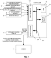
- Fig. 1 is an outline configuration diagram of a vehicle according to an embodiment of the present invention.
- This vehicle includes an internal combustion engine (hereinafter, referred to simply as an "engine”) as a driving source, and a rotation power of the engine 1 is input into a pump impeller 2a of a torque converter 2 including a lockup clutch 2c through its output shaft and is transmitted to driving wheels 7 from a turbine runner 2b through a first gear train 3, a transmission mechanism 4, a second gear train 5, and a differential device 6.
- engine internal combustion engine
- a rotation power of the engine 1 is input into a pump impeller 2a of a torque converter 2 including a lockup clutch 2c through its output shaft and is transmitted to driving wheels 7 from a turbine runner 2b through a first gear train 3, a transmission mechanism 4, a second gear train 5, and a differential device 6.
- the rotation power of the engine 1, that is, a torque is input, and a mechanical oil pump 10m driven by using a part of the power of the engine 1 and an electric oil pump 10e driven by receiving power supply from a battery 13 are provided.
- a hydraulic control circuit 11 for adjusting a pressure of an oil discharged from the mechanical oil pump 10m or the electric oil pump 10e, generating a required operating hydraulic pressure, and supplying it to each portion of the transmission mechanism 4 is provided.
- the transmission mechanism 4 includes a belt continuously variable transmission mechanism (hereinafter referred to as a "variator") 20 and a sub-transmission mechanism 30 provided in series with the variator 20.
- the phrase "provided in series” here means that the variator 20 and the sub-transmission mechanism 30 are arranged on the same power transmission path from the engine 1 to the driving wheels 7.
- the sub-transmission mechanism 30 may be directly connected to an output shaft of the variator 20 as in this embodiment or may be connected through the other transmission or power transmission mechanism (a gear train, for example).
- the variator 20 includes a primary pulley 21, a secondary pulley 22, and a V-belt 23 wound between each of the pulleys 21 and 22.
- a width of a V-groove is changed in accordance with a hydraulic pressure supplied to a primary pulley oil chamber 21a (hereinafter referred to as a "primary pulley pressure") Ppri and a hydraulic pressure supplied to a secondary pulley oil chamber 22a (hereinafter referred to as a "secondary pulley pressure”) Psec, whereby a contact radius between a V-belt 23 and each of the pulleys 21 and 22 changes, and a speed ratio Iva of the variator 20 variably changes continuously.
- the sub-transmission mechanism 30 is a transmission mechanism having two forward gear positions and one reverse gear position.
- the sub-transmission mechanism 30 includes a Ravigneaux planetary gear mechanism 31 composed by connecting carriers of two planetary gears and a plurality of friction engaging elements (a Low brake 32, a High clutch 33, a Rev brake 34) connected to a plurality of rotation elements constituting the Ravigneaux planetary gear mechanism 31 and changing their linkage states.
- a hydraulic pressure supplied to each of the friction engaging elements 32 to 34 and by changing engaged and disengaged states of each of the friction engaging elements 32 to 34, the speed ratio Is of the sub-transmission mechanism 30 can be changed.
- the Low brake 32 corresponds to a "first friction engaging element” according to this embodiment
- the Rev brake 34 to a "second friction engaging element", respectively.
- the gear position of the sub-transmission mechanism 30 becomes a first-speed position.
- the gear position of the sub-transmission mechanism 30 becomes a second-speed position with a speed ratio smaller than that of the first-speed position.
- the gear position of the sub-transmission mechanism 30 becomes a reverse position.
- a controller 12 is the controller 12 for comprehensively controlling operations of the engine 1 and the transmission mechanism 4, and as illustrated in Fig. 2 , it is constituted by a CPU 121, a storage device 122 made of a RAM and a ROM, an input interface 123, an output interface 124, and a bus 125 mutually connecting them.
- the controller 12 constitutes a "control device" according to this embodiment.
- an output signal of an accelerator pedal opening sensor 41 for detecting an accelerator pedal opening APO which is an operation amount of an accelerator pedal 51 by a driver an output signal of a primary rotation speed sensor 42 for detecting a primary pulley rotation speed Npri which is a rotation speed of the primary pulley 21, an output signal of a secondary rotation speed sensor 43 for detecting a secondary pulley rotation speed Nsec which is a rotation speed of the secondary pulley 22, an output signal of a vehicle speed sensor 44 for detecting a vehicle speed VSP, an output signal of an inhibitor switch 45 for detecting a position of a shift lever 50 and the like are input.
- an output signal from a brake liquid pressure sensor for detecting a brake liquid pressure BRP corresponding to an operation amount of a brake pedal and the like are input through the input interface 123.
- a control program of the engine 1, a shifting control program of the transmission mechanism 4, various maps and tables used in these programs are stored.
- the CPU 121 reads out and executes the program stored in the storage device 122, applies various types of arithmetic processing to the various signals input through the input interface 123, generates a fuel injection amount signal, an ignition timing signal, a throttle opening degree signal, and a shifting control signal and outputs the generated signals to the engine 1 and the hydraulic control circuit 11 through the output interface 124.
- Various values and their calculation results used by the CPU 121 in the arithmetic processing are stored in the storage device 122 as appropriate.
- the hydraulic control circuit 11 is constituted by a plurality of channels and a plurality of hydraulic control valves.
- the hydraulic control circuit 11 switches a supply path of the hydraulic pressure by controlling the plurality of hydraulic control valves on the basis of the shifting control signal from the controller 12, adjusts the required operating hydraulic pressure from the pressure of the oil discharged from the mechanical oil pump 10m or the electric oil pump 10e and supplies this operating hydraulic pressure to each portion of the transmission mechanism 4.
- the speed ratio Iva of the variator 20 and the speed ratio Is of the sub-transmission mechanism 30 are changed, and shifting of the transmission mechanism 4 is performed.
- the speed ratio of the variator 20 is changed toward the Lowest speed ratio during stop, and the hydraulic control of the primary pulley 21 described below is executed.
- the hydraulic control according to this embodiment will be described in detail, here.
- This Low return control is control for suppressing a sense of discomfort given to the driver due to insufficient driving force of the vehicle at start after the stop.
- the Low return control is executed basically by discharging the hydraulic pressure from the primary pulley oil chamber 21a to lower the primary pulley pressure while the secondary pulley pressure is maintained. By increasing the secondary pulley pressure together with the lowering of the primary pulley pressure, the Low return control can be executed rapidly, but power consumption amount of the electric oil pump 10e is increased. In this embodiment, too, the Low return control is executed basically by lowering only the primary pulley pressure without increasing the secondary pulley pressure.
- a lowest hydraulic pressure Ppri_low is usually set so that the belt slip does not occur in the primary pulley 21 with respect to an increase of an engine torque Te caused by stepping-on of the accelerator pedal 51. Therefore, even when the Low return control is executed, the primary pulley pressure is controlled so as not to fall under the lowest hydraulic pressure Ppri_low.
- Such belt slip occurs when the vehicle stops before the speed ratio Iva of the variator 20 reaches the Lowest speed ratio by sudden deceleration and moreover, when the shift lever 50 is operated from the D range to the R range via the N range after the stop or when it is operated from the R range to the D range via the N range.
- the belt slip can occur not only during stop but also when the vehicle is suddenly decelerated and reaches an extremely low speed immediately before the stop and the shift lever 50 is changed from the D range to the R range via the N range before the speed ratio Iva of the variator 20 reaches a target speed ratio Ivt set on the Low side or when it is changed from the R range to the D range via the N range. That is, the belt slip becomes a problem when the speed ratio Iva of the variator 20 is still on the High side than the target speed ratio Ivt after deceleration or stop whether it is before or after the stop and can occur when the shift lever 50 is changed from the running range to the running range via the non-running range.
- the target speed ratio Ivt when the belt slip becomes a problem may be the Lowest speed ratio or a speed ratio smaller than the Lowest speed ratio.
- the belt slip can occur when the shift lever 50 is changed from the D range to the D range via the N range or from the R range to the R range via the N range. That is, the belt slip can occur not only in the case of operation between the different running ranges but also in the case of a change between the same running ranges via the non-running range.
- the shift lever 50 is operated from the D range to the N range, if it is returned to the D range in a short period, since the Low brake 32 is not disengaged by a remaining pressure, the rotation speed difference does not occur between the input and output shafts of the Low brake 32.
- the controller 12 determines whether the speed ratio Iva of the variator 20 is the target speed ratio Ivt or not.
- the target speed ratio Ivt is set to the Lowest speed ratio.
- the controller 12 calculates an actual speed ratio Iva of the variator 20 on the basis of signals from the primary rotation speed sensor 42 and the secondary rotation speed sensor 43 and determines whether the calculated actual speed ratio Iva is the target speed ratio Ivt or not. If the speed ratio Iva of the variator 20 is the target speed ratio Ivt, the processing this time is finished, while if it is not the target speed ratio Ivt, the processing proceeds to Step S101.
- Step S101 the controller 12 determines whether the shift lever 50 has been operated from the N range to the D range or the R range. If the shift lever 50 has been changed from the N range to the D range or the R range, the processing proceeds to Step S102, while if the shift lever 50 is held in the N range, the D range or the R range, the processing proceeds to Step S105.
- the controller 12 detects a position of the shift lever 50 on the basis of a signal from the inhibitor switch 45 and determines whether it has been operated to the D range or the R range by comparing the position with a detection result previous time. Therefore, if the shift lever 50 is operated from the D range to the R range via the N range, by means of the operation from the N range to the R range, the processing proceeds to Step S102. If the shift lever 50 has not been operated or held in the range after the operation, the processing proceeds to Step S105.
- the controller 12 calculates an initial value Ppri_limin of a lower limit regulation value Ppri_lim of the primary pulley pressure.
- the initial value Ppri_limin of a lower limit regulation value Ppri_lim is set so that, if the primary pulley pressure is increased with a predetermined gradient ⁇ P, the primary pulley pressure reaches a predetermined pressure (predetermined oil pressure) P1 at a point of time when an engagement instruction to the Rev brake 34 is given and torque transmission is actually started at the Rev brake 34 (in other words, the torque capacity is generated) or before that.
- the predetermined gradient ⁇ P is a value set in advance, and if the increase of the primary pulley pressure is steep, there is a concern that the speed ratio Iva of the variator 20 is suddenly changed and it gives a sense of discomfort to the driver and thus, it is set to an appropriate value within a range not giving a sense of discomfort to the driver.
- the predetermined pressure P1 is a pressure calculated on the basis of a gear ratio of the Rev brake 34 to be engaged and the engine torque Te or the like in accordance with an operation state of the vehicle (the vehicle speed VSP, for example) and the operation of the shift lever 50 and is set so that the belt slip does not occur in the primary pulley 21 when the torque transmission is started in the Rev brake 34 and the inertia torque is input into the variator 20 from the sub-transmission mechanism 30 side.
- the engagement control of the Rev brake 34 is managed by time from the operation of the shift lever 50, and when the shift lever 50 is operated, time until the torque transmission is started in the Rev brake 34 is determined. Therefore, the initial value Ppri_limin of the lower limit regulation value Ppri_lim can be calculated on the basis of the predetermined pressure PI, the predetermined gradient ⁇ P, and the time until the torque transmission is started.
- timing when the primary pulley pressure reaches the predetermined pressure P1 desirably matches the timing when the torque transmission is started in the Rev brake 34 and the initial value Ppri_limin is desirably calculated so that the both timings match.
- the predetermined gradient ⁇ P may be set so that the primary pulley pressure reaches the predetermined pressure P1 when the both timings match or before the torque transmission is started in the Rev brake 34 after the initial value Ppri_limin is determined. That is, it is only necessary to set the initial value Ppri_limin or the predetermined gradient ⁇ P so that the primary pulley pressure reaches the predetermined pressure P1 by the time when the torque transmission is started at the latest.
- the controller 12 calculates an upper limit value Te_lim of the engine torque Te.
- the upper limit value Te_lim of the engine torque Te is set by considering a case where the timing when the torque transmission is started in the Rev brake 34 becomes earlier than the set timing.
- the upper limit value Te_lim of the engine torque Te is a value obtained by subtracting a torque-down amount set in advance or the torque-down amount corresponding to the inertia torque input into the variator 20 by generation of the torque capacity by the Rev brake 34 from the current engine torque Te.
- the current engine torque Te is an engine torque in an idle state if the accelerator pedal 51 is not stepped on such as when the vehicle is stopped.
- the controller 12 controls the engine 1 so that the engine torque Te becomes the upper limit value Te_lim of the engine torque Te.
- Step S105 the controller 12 determines whether the Rev brake 34 is being engaged or not.
- the controller 12 determines that engagement of the Rev brake 34 has been completed if the time since the shift lever 50 is operated to the R range reaches engagement completion time set in advance.
- the phrase "the engagement of the Rev brake 34 is completed" means that the hydraulic pressure supplied to the Rev brake 34 rises to a predetermined engagement pressure, and the Rev brake 34 comes to generate the predetermined torque capacity. If the engagement of the Rev brake 34 is not completed but is being engaged, the processing proceeds to Step S106, while if the engagement of the Rev brake 34 is completed, the processing proceeds to Step S113.
- Step S106 the controller 12 determines whether the torque transmission has been started in the Rev brake 34. That is, the controller 12 determines whether the Rev brake 34 is in a slip state or not. When the time from the operation of the shift lever 50 has reached slip start time set in advance, the controller 12 determines that the torque transmission has been started in the Rev brake 34. If the Rev brake 34 is not in the slip state and the torque transmission has not been started in the Rev brake 34, the processing proceeds to Step S107, while if the Rev brake 34 is in the slip state and the torque transmission has been started in the Rev brake 34, the processing proceeds to Step S108.
- the lower limit regulation value Ppri_lim since the initial value Ppri_limin is calculated so that the lower limit regulation value Ppri_lim becomes the predetermined pressure P1 at the point of time when the torque transmission is started in the Rev brake 34 or before that, if the Rev brake 34 enters the slip state, the lower limit regulation value Ppri_lim has become the predetermined pressure P1. Therefore, if the processing proceeds to Step S108, the lower limit regulation value Ppri_lim has become the predetermined pressure P1.
- the controller 12 maintains the upper limit value Te_lim of the engine torque Te.
- Step S108 the controller 12 cancels the upper limit value Te_lim of the engine torque Te. After the upper limit value Te_lim is cancelled, the controller 12 gradually increases the engine torque Te from the upper limit value Te_lim.
- the controller 12 updates the lower limit regulation value Ppri_lim by adding a predetermined addition value P2 to the current lower limit regulation value Ppri_lim.
- the predetermined addition value P2 is a value set in advance so that the lower limit regulation value Ppri_lim increases by the predetermined gradient ⁇ P.
- the lower limit regulation value Ppri_lim is held at the predetermined pressure P1 after the primary pulley pressure becomes the predetermined pressure P1.
- the controller 12 compares the updated lower limit regulation value Ppri_lim with a required pressure Ppri_ne of the primary pulley 21.
- the required pressure Ppri_ne is set to the higher hydraulic pressure in a hydraulic pressure calculated on the basis of the target speed ratio Ivt in order to change the speed ratio Iva of the variator 20 to the target speed ratio Ivt (Lowest speed ratio) and a lowest hydraulic pressure Ppri_low not generating the belt slip in the primary pulley 21 with respect to the torque transmitted from the engine 1.
- Step S111 If the current lower limit regulation value Ppri_lim is higher than the required pressure Ppri_ne, the processing proceeds to Step S111, while if the current lower limit regulation value Ppri_lim is not higher than the required pressure Ppri_ne, the processing proceeds to Step S112.
- Step S111 the controller 12 sets an instructed pressure (target hydraulic pressure) Ppri of the primary pulley 21 to the lower limit regulation value Ppri_lim.
- the primary pulley pressure is controlled on the basis of the lower limit regulation value Ppri_lim.
- Step S112 the controller 12 sets the instructed pressure Ppri of the primary pulley 21 to the required pressure Ppri_ne. As a result, the primary pulley pressure is controlled on the basis of the required pressure Ppri_ne.
- the instructed pressure Ppri of the primary pulley 21 is set to the lower limit regulation value Ppri_lim, and the subsequent lowering of the instructed pressure value Ppri is regulated.
- the speed ratio Iva of the variator 20 is controlled toward the Lowest speed ratio, and a state where the primary pulley pressure is too low when the Rev brake 34 is engaged is prevented, and occurrence of the belt slip in the primary pulley 21 can be suppressed.
- the speed ratio Iva of the variator 20 can be brought closer to the Lowest speed ratio by increasing an instructed pressure Psec of the secondary pulley 22. As described above, shifting of the variator 20 and suppression of the belt slip can be both realized.
- Step S113 the controller 12 cancels the upper limit value Te_lim of the engine torque Te. After the cancellation, the controller 12 increases the engine torque Te from the upper limit value Te_lim in a stepped manner.
- Step S114 the controller 12 cancels the lower limit regulation value Ppri_lim.
- the required pressure Ppri_ne is set to the instructed pressure Ppri of the primary pulley 21, and the primary pulley pressure is controlled on the basis of the required pressure Ppri_ne.
- Fig. 4 is a time chart when the hydraulic control according to this embodiment is not executed and lowering of the primary pulley pressure is not regulated.
- Fig. 5 is a time chart when the hydraulic control according to this embodiment is executed.
- the vehicle suddenly decelerates, and the vehicle speed VSP lowers.
- the Low brake 32 is engaged, while the lockup clutch 2c is disengaged, and the turbine rotation speed Nt lowers together with the lowering of the vehicle speed VSP.
- the target speed ratio Ivt of the variator 20 is changed toward the Lowest speed ratio, and down-shift according to a deviation of the actual speed ratio Iva of the variator 20 to the target speed ratio Ivt is carried out.
- the instructed pressure Ppri of the primary pulley 21 is lowered, and the speed ratio Iva of the variator 20 is changed to the Low side.
- the vehicle is stopped, and the vehicle speed VSP becomes 0 (zero).
- the target speed ratio Ivt is set to the Lowest speed ratio, but shifting of the actual speed ratio Iva of the variator 20 cannot catch up with the rapid deceleration and has not reached the Lowest speed ratio. Since each of the pulleys 21 and 22 of the variator 20 is not rotated, the speed ratio Iva of the variator 20 is held at a value during stop. Since the shift lever 50 is in the D range, the Low brake 32 is engaged, and the turbine rotation speed Nt also becomes zero. Due to the stop, the secondary pulley pressure required for preventing the belt slip becomes smaller and thus, the instructed pressure Psec of the secondary pulley lowers.
- the shift lever 50 is operated from the D range to the R range via the N range.
- the shift lever 50 is operated from the D range to the N range, and at the time t4, the shift lever 50 in the N range is operated to the R range.
- the Low brake 32 of the sub-transmission mechanism 30 is disengaged.
- the rotation elements closer to the engine 1 side than the Low brake 32 are made capable of free rotation.
- the rotation elements such as the pulleys 21 and 22 are rotated by the torque transmitted from the engine 1, and at the time t3, the turbine rotation speed Nt starts rising.
- the speed ratio Iva of the variator 20 is made changeable.
- the instructed pressure Psec of the secondary pulley 22 is increased in a stepped manner.
- the instructed pressure Psec of the secondary pulley 22 is increased in the stepped manner as described above and the instructed pressure Ppri of the primary pulley 21 is also increased in accordance with the increase of the secondary pulley pressure Psec to suppress the rapid change of the speed ratio Iva.
- the speed ratio Iva is changed to the Low side.
- pre-charging to the Rev brake 34 is started.
- the pre-charging is, concerning the Rev brake 34, an operation of rapidly changing to a state immediately before the torque capacity is generated in the Rev brake 34 by increasing the hydraulic pressure to be supplied to the Rev brake 34 in the stepped manner.
- the instructed pressure Ppri of the primary pulley 21 reaches the lowest hydraulic pressure Ppri_low at which the belt slip does not occur in the primary pulley 21 with respect to the torque transmitted from the engine 1, the instructed pressure Ppri of the primary pulley 21 is held at this lowest hydraulic pressure Ppri_low.
- the instructed pressure Ppri of the primary pulley 21 is held at the lowest hydraulic pressure Ppri_low, by raising the instructed pressure Psec of the secondary pulley 22, the speed ratio Iva of the variator 20 is changed to the Low side.
- the lowest hydraulic pressure Ppri_low is set so that the belt slip does not occur in the variator 20 with respect to the torque input from the engine 1, but the fact that the shift lever 50 is operated from the D range to the R range, and the inertia torque is input from the sub-transmission mechanism 30 side is not considered.
- the belt gripping force becomes insufficient, and there is a concern that the belt slip occurs in the variator 20.
- the shift lever 50 is operated from the D range to the R range via the N range.
- the shift lever 50 is operated form the D range to the N range, and at the time t4, it is operated from the N range to the R range.
- the speed ratio Iva is made changeable in the variator 20, and after the turbine rotation speed Nt starts rising, the down-shift toward the Lowest speed ratio of the variator 20 is resumed.
- the required pressure Ppri_ne of the primary pulley 21 at the time t4 and after is indicated by a dot line
- the lower limit regulation value Ppri_lim is indicated by a two-dot chain line.
- the upper limit value Te_lim of the engine torque Te is calculated, and by setting the engine torque Te to the upper limit value Te_lim, the engine torque Te lowers.
- the lower limit regulation value Ppri_lim is set to the instructed pressure Ppri of the primary pulley 21, and the instructed pressure Ppri of the primary pulley 21 becomes higher than the case where the required pressure Ppri_ne is set.
- the required pressure Ppri_ne is continuously set to the instructed pressure Ppri of the primary pulley 21 at the time t5 and after.
- the instructed pressure Psec of the secondary pulley 22 is also made high, and since an actual pressure of each of the pulleys 21 and 22 is changed on the basis of these instructed pressures Ppri and Psec, the change of the speed ratio Iva toward the Lowest speed ratio is continued at the time t5 and after.
- the pre-charging of the Rev brake 34 is finished, and the Rev brake 34 starts torque transmission.
- the lower limit regulation value Ppri_lim has reached the predetermined pressure P1.
- the upper limit value Te_lim of the engine torque Te is cancelled, and the engine torque Te is gradually increased.
- the instructed pressure Ppri of the primary pulley 21 is held at the predetermined pressure P1.
- the speed ratio Iva is held at a value at that point of time.
- the required pressure Ppri_ne is increased in order to hold the speed ratio Iva. Since the required pressure Ppri_ne becomes higher than the lower limit regulation value Ppri_lim, the required pressure Ppri_ne is set to the instructed pressure Ppri of the primary pulley 21.
- the lower limit regulation value Ppri_lim is increased from the initial value Ppri_limin by the predetermined gradient ⁇ P, but the initial value Ppri_limin may be set to the predetermined pressure P1 at the same time as when the shift lever 50 is operated from the N range to the R range.
- the lower limit regulation value Ppri_lim is compared with the required pressure Ppri_ne, and the higher one is set to the instructed pressure Ppri of the primary pulley 21 and thus, when the instructed pressure Ppri of the primary pulley 21 is switched from the required pressure Ppri_ne to the lower limit regulation value Ppri_lim, a change of the actual pressure of the primary pulley 21 is switched from lowering to increase, whereby under-chute can occur in the actual pressure.
- the lower limit regulation value Ppri_lim of the primary pulley 21 by setting the lower limit regulation value Ppri_lim of the primary pulley 21 to the predetermined pressure P1 at the same time as when the operation to the R range, the lower limit regulation value Ppri_lim can be made higher than the required pressure Ppri_ne at the same time as the operation to the R range.
- the under-chute which occurs when the instructed pressure Ppri of the primary pulley 21 is switched from the required pressure Ppri_ne to the lower limit regulation value Ppri_lim can be suppressed.
- Control of the aforementioned variation can be easily realized by setting the initial value Ppri_limin of the lower limit regulation value Ppri_lim to the predetermined pressure P1. Since the under-chute is suppressed, the belt gripping force is prevented from being insufficient reliably when the torque transmission is started in the Rev brake 34.
- the lower limit regulation value Ppri_lim may be increased from the initial value Ppri_limin larger than the instructed pressure Ppri at that point of time by the predetermined gradient ⁇ P.
- the instructed pressure Ppri of the primary pulley 21 becomes excessively high, and shifting of the variator 20 to the High side can be prevented.
- lowering of the primary pulley pressure after the operation may be prohibited by holding the primary pulley pressure at a point of time when the shift lever 50 is operated to the R range.
- Such control can realize an increase of the lower limit regulation value Ppri_lim from the initial value Ppri_limin after the operation to the R range, while the required pressure Ppri_ne of the primary pulley 21 is held. If the required pressure Ppri_ne is not smaller than the predetermined pressure PI, the required pressure Ppri_ne is set to the instructed pressure Ppri of the primary pulley 21 at all times.
- the lower limit regulation value Ppri_lim increases, and when it becomes higher than the required pressure Ppri_ne, the lower limit regulation value Ppri_lim is set to the instructed pressure Ppri of the primary pulley 21.
- the instructed pressure Ppri of the primary pulley 21 is switched from the required pressure Ppri_ne to the lower limit regulation value Ppri_lim, the actual pressure of the primary pulley 21 is only increased from a certain state and thus, the under-chute can be suppressed as compared with the case of an increase from the lowered state, and when the torque transmission is started in the Rev brake 34, running short of the belt gripping force can be suppressed.
- the torque transmission is started in the Rev brake 34, and even if the inertia torque is input into the variator 20, occurrence of the belt slip on the primary pulley 21 can be suppressed.
- the belt slip on the primary pulley 21 can be similarly suppressed.
- the operation of the shift lever 50 is not limited to the operation between the same running range but may be an operation between different running ranges. For example, it may be a case where the shift lever 50 is operated from the D range to the D range via the N range, and after the rotation speed difference is generated between the input and output shafts of the Low brake 32 due to the lowering of the hydraulic pressure of the Low brake 32, the shift lever 50 is returned to the D range, and the belt slip on the primary pulley 21 can be similarly suppressed.
- the belt slip on the primary pulley 21 can be suppressed.
- the engine 1 is used as a driving source of the vehicle, but an electric motor may be used instead of the engine 1, and an internal combustion engine and the electric motor may be used in combination.
- the electric motor may have only a function as a generator or may be a motor generator serving both the functions of the generator and a power generator.
- the vehicle to which the present invention is applied may be a vehicle including a forward/reverse switching mechanism instead of the sub-transmission mechanism 30.
Abstract
Description
- The present invention relates to a vehicle control device and a vehicle control method which execute down-shift in conjunction with a change of a shift range.
-
JP2012-247024 - In a vehicle including a friction engaging element between the variator and a driving wheel (a forward/reverse switching mechanism or a sub-transmission mechanism, for example), the speed ratio of the variator is changed to the Lowest speed ratio and the friction engaging element in a disengaged state is engaged in accordance with a range change of a shift lever or the like, belt slip can occur in the variator due to an input of an inertia torque from the driving wheel side.
- Specifically, in a vehicle including a sub-transmission mechanism as the friction engaging element, when the vehicle is stopped before the speed ratio becomes the Lowest speed ratio and moreover, a shift lever is changed from a D (drive) range to an R (reverse) range via an N (neutral) range after the stop, the friction engaging element for forward running in the engaged state is disengaged by the range change to the N (neutral) range. By means of the disengagement of the friction engaging element, each pulley in the variator is rotated by the torque transmitted from an engine, and a shaft of the friction engaging element on the variator side is also rotated. On the other hand, a shaft of the friction engaging element on the driving wheel side is not rotated since the vehicle is stopped. Therefore, in the friction engaging element, a rotation speed difference occurs between an input and output shafts.
- In the variator, the speed ratio can be changed by rotation of each pulley. Thus, control of the speed ratio toward the Lowest speed ratio is started, and the primary pulley pressure is lowered.
- If a range change to the R range is performed in such a state, and a friction engaging element for reverse running starts engagement, a torque (inertia torque) according to the rotation speed difference between the input and output shafts of the friction engaging element for reverse running is input to the variator not only from the engine side but also from the driving wheel side. Therefore, to the variator, the torque is input both from the engine and the driving wheel. If such torque is input when the speed ratio of the variator is being changed toward the Lowest speed ratio, that is, when the primary pulley pressure is being lowered, a belt gripping force with respect to the input torque is insufficient in the primary pulley, and the belt slip occurs.
- Such belt slip can also occur not only during stop but when the shift lever is changed from the D range to the R range in a state where the speed ratio of the variator is still on a High side rather than a target speed ratio after sudden deceleration from a middle or a high vehicle speed to a low vehicle speed, for example. Moreover, it can occur not only in range switching to a different running range but when the shift lever is changed between the same running range (D range, for example) via a non-running range.
- According to an aspect of the present invention, a vehicle control device adapted to control a vehicle including a variator provided in a power transmission path between a driving source and a driving wheel of a vehicle; and a friction engaging element provided between the variator and the driving wheel, engaged when a running range is selected, while disengaged when a non-running range is selected and shutting off transmission of power through the power transmission path, is provided. In this aspect, an operating state of the vehicle is detected; a target speed ratio of the variator according to the operating state of the vehicle is set; if an actual speed ratio of the variator is smaller than the target speed ratio, shifting control of lowering a supply hydraulic pressure to a primary pulley of the variator and increasing the speed ratio of the variator is executed; and when the shifting range is switched from the non-running range to the running range during execution of the shifting control, lowering of the supply hydraulic pressure to the primary pulley after the switching is regulated.
- According to another aspect of the present invention, a vehicle control method for a vehicle including a variator provided in a power transmission path between a driving source and a driving wheel of the vehicle; and a friction engaging element provided between the variator and the driving wheel, engaged when a running range is selected, while disengaged when a non-running range is selected and shutting off transmission of power through the power transmission path. In this aspect, the vehicle control method includes detecting an operating state of the vehicle; setting a target speed ratio of the variator according to the operating state of the vehicle; if an actual speed ratio of the variator is smaller than the target speed ratio, executing shifting control of lowering a supply hydraulic pressure to a primary pulley of the variator and increasing the speed ratio of the variator; and when the shifting range is switched from the non-running range to the running range during execution of the shifting control, regulating lowering of the supply hydraulic pressure to the primary pulley after the switching.
- According to the aforementioned aspect, when the friction engaging element in the disengaged state is to be engaged during down-shift of the variator, occurrence of the belt slip in the variator can be suppressed.
-
-
Fig. 1 is an outline configuration diagram of a vehicle according to an embodiment of the present invention. -
Fig. 2 is an outline configuration diagram of a controller according to the embodiment. -
Fig. 3 is a flowchart illustrating contents of hydraulic control executed by the controller. -
Fig. 4 is a time chart illustrating an operation of the entire vehicle when the hydraulic control is not used. -
Fig. 5 is a time chart illustrating the operation of the entire vehicle when lowering of a hydraulic pressure is regulated by the hydraulic control. - Hereinafter, an embodiment of the present invention will be described by referring to the attached drawings.
- In the following description, a "speed ratio" is a value (=N1/N2) obtained by dividing an input rotation speed N1 of a transmission mechanism by an output rotation speed N2 of the transmission mechanism, and if the speed ratio is large, it is referred to be "on a Low side", while if the speed ratio is small, it is referred to be "on a High side". Moreover, shifting in which the speed ratio is changed from a current state to a Low side is referred to as down-shift, while shifting to be changed to the High side is referred to as up-shift.
-
Fig. 1 is an outline configuration diagram of a vehicle according to an embodiment of the present invention. This vehicle includes an internal combustion engine (hereinafter, referred to simply as an "engine") as a driving source, and a rotation power of theengine 1 is input into apump impeller 2a of atorque converter 2 including alockup clutch 2c through its output shaft and is transmitted to drivingwheels 7 from aturbine runner 2b through afirst gear train 3, atransmission mechanism 4, asecond gear train 5, and adifferential device 6. - Into the
transmission mechanism 4, the rotation power of theengine 1, that is, a torque is input, and amechanical oil pump 10m driven by using a part of the power of theengine 1 and anelectric oil pump 10e driven by receiving power supply from abattery 13 are provided. Moreover, in thetransmission mechanism 4, ahydraulic control circuit 11 for adjusting a pressure of an oil discharged from themechanical oil pump 10m or theelectric oil pump 10e, generating a required operating hydraulic pressure, and supplying it to each portion of thetransmission mechanism 4 is provided. - The
transmission mechanism 4 includes a belt continuously variable transmission mechanism (hereinafter referred to as a "variator") 20 and asub-transmission mechanism 30 provided in series with thevariator 20. The phrase "provided in series" here means that thevariator 20 and thesub-transmission mechanism 30 are arranged on the same power transmission path from theengine 1 to thedriving wheels 7. Thesub-transmission mechanism 30 may be directly connected to an output shaft of thevariator 20 as in this embodiment or may be connected through the other transmission or power transmission mechanism (a gear train, for example). - The
variator 20 includes aprimary pulley 21, asecondary pulley 22, and a V-belt 23 wound between each of thepulleys variator 20, a width of a V-groove is changed in accordance with a hydraulic pressure supplied to a primarypulley oil chamber 21a (hereinafter referred to as a "primary pulley pressure") Ppri and a hydraulic pressure supplied to a secondarypulley oil chamber 22a (hereinafter referred to as a "secondary pulley pressure") Psec, whereby a contact radius between a V-belt 23 and each of thepulleys variator 20 variably changes continuously. - The
sub-transmission mechanism 30 is a transmission mechanism having two forward gear positions and one reverse gear position. Thesub-transmission mechanism 30 includes a Ravigneauxplanetary gear mechanism 31 composed by connecting carriers of two planetary gears and a plurality of friction engaging elements (aLow brake 32, aHigh clutch 33, a Rev brake 34) connected to a plurality of rotation elements constituting the Ravigneauxplanetary gear mechanism 31 and changing their linkage states. By adjusting a hydraulic pressure supplied to each of thefriction engaging elements 32 to 34 and by changing engaged and disengaged states of each of thefriction engaging elements 32 to 34, the speed ratio Is of thesub-transmission mechanism 30 can be changed. Here, theLow brake 32 corresponds to a "first friction engaging element" according to this embodiment, and theRev brake 34 to a "second friction engaging element", respectively. - Specifically, when the
Low brake 32 is engaged, and when theHigh clutch 33 and theRev brake 34 are disengaged, the gear position of thesub-transmission mechanism 30 becomes a first-speed position. When theHigh clutch 33 is engaged, and when theLow brake 32 and theRev brake 34 are disengaged, the gear position of thesub-transmission mechanism 30 becomes a second-speed position with a speed ratio smaller than that of the first-speed position. Moreover, when theRev brake 34 is engaged, and when theLow brake 32 and theHigh clutch 33 are disengaged, the gear position of thesub-transmission mechanism 30 becomes a reverse position. - By changing the speed ratio Iva of the
variator 20 and the speed ratio Is of thesub-transmission mechanism 30, a speed ratio I of theentire transmission mechanism 4 is changed. - A
controller 12 is thecontroller 12 for comprehensively controlling operations of theengine 1 and thetransmission mechanism 4, and as illustrated inFig. 2 , it is constituted by aCPU 121, astorage device 122 made of a RAM and a ROM, aninput interface 123, anoutput interface 124, and abus 125 mutually connecting them. Thecontroller 12 constitutes a "control device" according to this embodiment. - Into the
input interface 123, as signals indicating an actual operating state of theengine 1 and the automatic transmission, an output signal of an acceleratorpedal opening sensor 41 for detecting an accelerator pedal opening APO which is an operation amount of anaccelerator pedal 51 by a driver, an output signal of a primaryrotation speed sensor 42 for detecting a primary pulley rotation speed Npri which is a rotation speed of theprimary pulley 21, an output signal of a secondaryrotation speed sensor 43 for detecting a secondary pulley rotation speed Nsec which is a rotation speed of thesecondary pulley 22, an output signal of avehicle speed sensor 44 for detecting a vehicle speed VSP, an output signal of aninhibitor switch 45 for detecting a position of ashift lever 50 and the like are input. Other than the above, into thecontroller 12, an output signal of an engine rotation speed sensor for detecting an engine rotation speed Ne which is a rotation speed of an output shaft of theengine 1, an output signal of a turbine rotation speed sensor for detecting a turbine rotation speed Nt which is a rotation speed of an output shaft of atorque converter 2, an output signal from a brake liquid pressure sensor for detecting a brake liquid pressure BRP corresponding to an operation amount of a brake pedal and the like are input through theinput interface 123. - In the
storage device 122, a control program of theengine 1, a shifting control program of thetransmission mechanism 4, various maps and tables used in these programs are stored. TheCPU 121 reads out and executes the program stored in thestorage device 122, applies various types of arithmetic processing to the various signals input through theinput interface 123, generates a fuel injection amount signal, an ignition timing signal, a throttle opening degree signal, and a shifting control signal and outputs the generated signals to theengine 1 and thehydraulic control circuit 11 through theoutput interface 124. Various values and their calculation results used by theCPU 121 in the arithmetic processing are stored in thestorage device 122 as appropriate. - The
hydraulic control circuit 11 is constituted by a plurality of channels and a plurality of hydraulic control valves. Thehydraulic control circuit 11 switches a supply path of the hydraulic pressure by controlling the plurality of hydraulic control valves on the basis of the shifting control signal from thecontroller 12, adjusts the required operating hydraulic pressure from the pressure of the oil discharged from themechanical oil pump 10m or theelectric oil pump 10e and supplies this operating hydraulic pressure to each portion of thetransmission mechanism 4. As a result, the speed ratio Iva of thevariator 20 and the speed ratio Is of thesub-transmission mechanism 30 are changed, and shifting of thetransmission mechanism 4 is performed. - In this embodiment, the speed ratio of the
variator 20 is changed toward the Lowest speed ratio during stop, and the hydraulic control of theprimary pulley 21 described below is executed. The hydraulic control according to this embodiment will be described in detail, here. - For example, assume a case where deceleration is carried out in a state where the
shift lever 50 is in the D range, and the vehicle is stopped before the speed ratio Iva of thevariator 20 reaches the Lowest speed ratio. In this case, since theLow brake 32 is in the engaged state and in a state where thedriving wheels 7 not rotating and thevariator 20 are connected through theLow brake 32, each of thepulleys variator 20 is not rotated, and the speed ratio Iva of thevariator 20 cannot be changed to the Lowest speed ratio. If theshift lever 50 is changed from the D range to the R range via the N range in this state, theLow brake 32 of thesub-transmission mechanism 30 is disengaged in accordance with a shift operation to the N range, and moreover, theRev brake 34 is engaged in accordance with the shift operation to the R range. Here, during a period since theLow brake 32 is disengaged until theRev brake 34 is engaged, all thefriction engaging elements 32 to 34 of thesub-transmission mechanism 30 are in the disengaged state, and connection between the variator 20 and thedriving wheels 7 is disengaged and thus, each of thepulleys variator 20 can be rotated by the torque transmitted from theengine 1. In response to that, in thevariator 20, control for changing the speed ratio Iva to the Lowest speed ratio during stop (hereinafter referred to as "Low return control") is executed. - This Low return control is control for suppressing a sense of discomfort given to the driver due to insufficient driving force of the vehicle at start after the stop. The Low return control is executed basically by discharging the hydraulic pressure from the primary
pulley oil chamber 21a to lower the primary pulley pressure while the secondary pulley pressure is maintained. By increasing the secondary pulley pressure together with the lowering of the primary pulley pressure, the Low return control can be executed rapidly, but power consumption amount of theelectric oil pump 10e is increased. In this embodiment, too, the Low return control is executed basically by lowering only the primary pulley pressure without increasing the secondary pulley pressure. - For the primary pulley pressure, a lowest hydraulic pressure Ppri_low is usually set so that the belt slip does not occur in the
primary pulley 21 with respect to an increase of an engine torque Te caused by stepping-on of theaccelerator pedal 51. Therefore, even when the Low return control is executed, the primary pulley pressure is controlled so as not to fall under the lowest hydraulic pressure Ppri_low. - However, by engaging the
Rev brake 34 in the disengaged state (including a slip state where a substantial torque capacity is not generated) during execution of the Low return control, if the inertia torque is input from thesub-transmission mechanism 30 side to thevariator 20, even if the primary pulley pressure is held at the lowest hydraulic pressure Ppri_low or more, a belt gripping force in theprimary pulley 21 is not sufficient with respect to the input torque, and the belt slip can occur on theprimary pulley 21. - If the
shift lever 50 is operated to the N range and theLow brake 32 of thesub-transmission mechanism 30 is disengaged during stop, the rotation speed of the shaft of theRev brake 34 on thedriving wheels 7 side is still zero, the shaft of theRev brake 34 on thevariator 20 side is rotated together with thesecondary pulley 22. As a result, in theRev brake 34, a rotation speed difference according to a gear ratio in theRev brake 34 occurs between the input and output shafts. If theRev brake 34 is engaged in this state, a large inertia torque is input into the input shaft (shaft on thevariator 20 side) of theRev brake 34 from the drivingwheels 7 side, and moreover, this inertia torque is input also to thevariator 20. - As described above, when the inertia torque is input to the
variator 20 also from thesub-transmission mechanism 30 side in addition to the torque input from theengine 1 side, the belt gripping force in theprimary pulley 21 becomes insufficient, and the belt slip occurs. - Such belt slip occurs when the vehicle stops before the speed ratio Iva of the
variator 20 reaches the Lowest speed ratio by sudden deceleration and moreover, when theshift lever 50 is operated from the D range to the R range via the N range after the stop or when it is operated from the R range to the D range via the N range. - However, the belt slip can occur not only during stop but also when the vehicle is suddenly decelerated and reaches an extremely low speed immediately before the stop and the
shift lever 50 is changed from the D range to the R range via the N range before the speed ratio Iva of thevariator 20 reaches a target speed ratio Ivt set on the Low side or when it is changed from the R range to the D range via the N range. That is, the belt slip becomes a problem when the speed ratio Iva of thevariator 20 is still on the High side than the target speed ratio Ivt after deceleration or stop whether it is before or after the stop and can occur when theshift lever 50 is changed from the running range to the running range via the non-running range. The target speed ratio Ivt when the belt slip becomes a problem may be the Lowest speed ratio or a speed ratio smaller than the Lowest speed ratio. - Moreover, the belt slip can occur when the
shift lever 50 is changed from the D range to the D range via the N range or from the R range to the R range via the N range. That is, the belt slip can occur not only in the case of operation between the different running ranges but also in the case of a change between the same running ranges via the non-running range. However, for example, though theshift lever 50 is operated from the D range to the N range, if it is returned to the D range in a short period, since theLow brake 32 is not disengaged by a remaining pressure, the rotation speed difference does not occur between the input and output shafts of theLow brake 32. That is, after the change from the running range to the non-running range, the remaining pressure of the friction engaging element on the disengaged side lowers and the rotation speed difference actually begins to emerge and then, if theshift lever 50 is returned from the non-running range to the same running range before the speed ratio Iva of thevariator 20 reaches the target speed ratio Ivt set on the Low side, the belt slip can occur. - The hydraulic control according to this embodiment will be described below by referring to a flowchart illustrated in
Fig. 3 by using a case where theshift lever 50 in the D range is operated to the R range via the N range after the stop as an example. - At Step S100, the
controller 12 determines whether the speed ratio Iva of thevariator 20 is the target speed ratio Ivt or not. In this embodiment, the target speed ratio Ivt is set to the Lowest speed ratio. Thecontroller 12 calculates an actual speed ratio Iva of thevariator 20 on the basis of signals from the primaryrotation speed sensor 42 and the secondaryrotation speed sensor 43 and determines whether the calculated actual speed ratio Iva is the target speed ratio Ivt or not. If the speed ratio Iva of thevariator 20 is the target speed ratio Ivt, the processing this time is finished, while if it is not the target speed ratio Ivt, the processing proceeds to Step S101. - At Step S101, the
controller 12 determines whether theshift lever 50 has been operated from the N range to the D range or the R range. If theshift lever 50 has been changed from the N range to the D range or the R range, the processing proceeds to Step S102, while if theshift lever 50 is held in the N range, the D range or the R range, the processing proceeds to Step S105. Thecontroller 12 detects a position of theshift lever 50 on the basis of a signal from theinhibitor switch 45 and determines whether it has been operated to the D range or the R range by comparing the position with a detection result previous time. Therefore, if theshift lever 50 is operated from the D range to the R range via the N range, by means of the operation from the N range to the R range, the processing proceeds to Step S102. If theshift lever 50 has not been operated or held in the range after the operation, the processing proceeds to Step S105. - At Step S102, the
controller 12 calculates an initial value Ppri_limin of a lower limit regulation value Ppri_lim of the primary pulley pressure. The initial value Ppri_limin of a lower limit regulation value Ppri_lim is set so that, if the primary pulley pressure is increased with a predetermined gradient ΔP, the primary pulley pressure reaches a predetermined pressure (predetermined oil pressure) P1 at a point of time when an engagement instruction to theRev brake 34 is given and torque transmission is actually started at the Rev brake 34 (in other words, the torque capacity is generated) or before that. The predetermined gradient ΔP is a value set in advance, and if the increase of the primary pulley pressure is steep, there is a concern that the speed ratio Iva of thevariator 20 is suddenly changed and it gives a sense of discomfort to the driver and thus, it is set to an appropriate value within a range not giving a sense of discomfort to the driver. The predetermined pressure P1 is a pressure calculated on the basis of a gear ratio of theRev brake 34 to be engaged and the engine torque Te or the like in accordance with an operation state of the vehicle (the vehicle speed VSP, for example) and the operation of theshift lever 50 and is set so that the belt slip does not occur in theprimary pulley 21 when the torque transmission is started in theRev brake 34 and the inertia torque is input into the variator 20 from thesub-transmission mechanism 30 side. - The engagement control of the
Rev brake 34 is managed by time from the operation of theshift lever 50, and when theshift lever 50 is operated, time until the torque transmission is started in theRev brake 34 is determined. Therefore, the initial value Ppri_limin of the lower limit regulation value Ppri_lim can be calculated on the basis of the predetermined pressure PI, the predetermined gradient ΔP, and the time until the torque transmission is started. - Here, timing when the primary pulley pressure reaches the predetermined pressure P1 desirably matches the timing when the torque transmission is started in the
Rev brake 34 and the initial value Ppri_limin is desirably calculated so that the both timings match. Moreover, the predetermined gradient ΔP may be set so that the primary pulley pressure reaches the predetermined pressure P1 when the both timings match or before the torque transmission is started in theRev brake 34 after the initial value Ppri_limin is determined. That is, it is only necessary to set the initial value Ppri_limin or the predetermined gradient ΔP so that the primary pulley pressure reaches the predetermined pressure P1 by the time when the torque transmission is started at the latest. - At Step S103, the
controller 12 calculates an upper limit value Te_lim of the engine torque Te. The upper limit value Te_lim of the engine torque Te is set by considering a case where the timing when the torque transmission is started in theRev brake 34 becomes earlier than the set timing. The upper limit value Te_lim of the engine torque Te is a value obtained by subtracting a torque-down amount set in advance or the torque-down amount corresponding to the inertia torque input into thevariator 20 by generation of the torque capacity by theRev brake 34 from the current engine torque Te. The current engine torque Te is an engine torque in an idle state if theaccelerator pedal 51 is not stepped on such as when the vehicle is stopped. - At Step S104, the
controller 12 controls theengine 1 so that the engine torque Te becomes the upper limit value Te_lim of the engine torque Te. - At Step S105, the
controller 12 determines whether theRev brake 34 is being engaged or not. Thecontroller 12 determines that engagement of theRev brake 34 has been completed if the time since theshift lever 50 is operated to the R range reaches engagement completion time set in advance. The phrase "the engagement of theRev brake 34 is completed" means that the hydraulic pressure supplied to theRev brake 34 rises to a predetermined engagement pressure, and theRev brake 34 comes to generate the predetermined torque capacity. If the engagement of theRev brake 34 is not completed but is being engaged, the processing proceeds to Step S106, while if the engagement of theRev brake 34 is completed, the processing proceeds to Step S113. - At Step S106, the
controller 12 determines whether the torque transmission has been started in theRev brake 34. That is, thecontroller 12 determines whether theRev brake 34 is in a slip state or not. When the time from the operation of theshift lever 50 has reached slip start time set in advance, thecontroller 12 determines that the torque transmission has been started in theRev brake 34. If theRev brake 34 is not in the slip state and the torque transmission has not been started in theRev brake 34, the processing proceeds to Step S107, while if theRev brake 34 is in the slip state and the torque transmission has been started in theRev brake 34, the processing proceeds to Step S108. - In this embodiment, since the initial value Ppri_limin is calculated so that the lower limit regulation value Ppri_lim becomes the predetermined pressure P1 at the point of time when the torque transmission is started in the
Rev brake 34 or before that, if theRev brake 34 enters the slip state, the lower limit regulation value Ppri_lim has become the predetermined pressure P1. Therefore, if the processing proceeds to Step S108, the lower limit regulation value Ppri_lim has become the predetermined pressure P1. - At Step S107, the
controller 12 maintains the upper limit value Te_lim of the engine torque Te. - At Step S108, the
controller 12 cancels the upper limit value Te_lim of the engine torque Te. After the upper limit value Te_lim is cancelled, thecontroller 12 gradually increases the engine torque Te from the upper limit value Te_lim. - As described above, by lowering the engine torque Te until the slip start time has elapsed after the operation of the
shift lever 50, even if actual time from the operation of theshift lever 50 until the torque transmission is started in theRev brake 34 is shorter than the slip start time and theRev brake 34 generates the torque capacity before elapse of the slip start time, the belt slip in theprimary pulley 21 can be suppressed. - At Step S109, the
controller 12 updates the lower limit regulation value Ppri_lim by adding a predetermined addition value P2 to the current lower limit regulation value Ppri_lim. The predetermined addition value P2 is a value set in advance so that the lower limit regulation value Ppri_lim increases by the predetermined gradient ΔP. The lower limit regulation value Ppri_lim is held at the predetermined pressure P1 after the primary pulley pressure becomes the predetermined pressure P1. - At Step S110, the
controller 12 compares the updated lower limit regulation value Ppri_lim with a required pressure Ppri_ne of theprimary pulley 21. The required pressure Ppri_ne is set to the higher hydraulic pressure in a hydraulic pressure calculated on the basis of the target speed ratio Ivt in order to change the speed ratio Iva of the variator 20 to the target speed ratio Ivt (Lowest speed ratio) and a lowest hydraulic pressure Ppri_low not generating the belt slip in theprimary pulley 21 with respect to the torque transmitted from theengine 1. If the current lower limit regulation value Ppri_lim is higher than the required pressure Ppri_ne, the processing proceeds to Step S111, while if the current lower limit regulation value Ppri_lim is not higher than the required pressure Ppri_ne, the processing proceeds to Step S112. - At Step S111, the
controller 12 sets an instructed pressure (target hydraulic pressure) Ppri of theprimary pulley 21 to the lower limit regulation value Ppri_lim. As a result, the primary pulley pressure is controlled on the basis of the lower limit regulation value Ppri_lim. - At Step S112, the
controller 12 sets the instructed pressure Ppri of theprimary pulley 21 to the required pressure Ppri_ne. As a result, the primary pulley pressure is controlled on the basis of the required pressure Ppri_ne. - As described above, if the lower limit regulation value Ppri_lim exceeds the required pressure Ppri_ne, the instructed pressure Ppri of the
primary pulley 21 is set to the lower limit regulation value Ppri_lim, and the subsequent lowering of the instructed pressure value Ppri is regulated. As a result, the speed ratio Iva of thevariator 20 is controlled toward the Lowest speed ratio, and a state where the primary pulley pressure is too low when theRev brake 34 is engaged is prevented, and occurrence of the belt slip in theprimary pulley 21 can be suppressed. - When the instructed pressure Ppri of the
primary pulley 21 is set to the lower limit regulation value Ppri_lim, the speed ratio Iva of thevariator 20 can be brought closer to the Lowest speed ratio by increasing an instructed pressure Psec of thesecondary pulley 22. As described above, shifting of thevariator 20 and suppression of the belt slip can be both realized. - At Step S113, the
controller 12 cancels the upper limit value Te_lim of the engine torque Te. After the cancellation, thecontroller 12 increases the engine torque Te from the upper limit value Te_lim in a stepped manner. - At Step S114, the
controller 12 cancels the lower limit regulation value Ppri_lim. As a result, the required pressure Ppri_ne is set to the instructed pressure Ppri of theprimary pulley 21, and the primary pulley pressure is controlled on the basis of the required pressure Ppri_ne. - Subsequently, the hydraulic control according to this embodiment will be described by referring to a time chart.
Fig. 4 is a time chart when the hydraulic control according to this embodiment is not executed and lowering of the primary pulley pressure is not regulated.Fig. 5 is a time chart when the hydraulic control according to this embodiment is executed. - First, the case where the hydraulic control of this embodiment is not executed will be described by referring to
Fig. 4 . - At time t0, the vehicle suddenly decelerates, and the vehicle speed VSP lowers. Here, the
Low brake 32 is engaged, while thelockup clutch 2c is disengaged, and the turbine rotation speed Nt lowers together with the lowering of the vehicle speed VSP. With the lowering of the vehicle speed VSP, the target speed ratio Ivt of thevariator 20 is changed toward the Lowest speed ratio, and down-shift according to a deviation of the actual speed ratio Iva of the variator 20 to the target speed ratio Ivt is carried out. As a result, the instructed pressure Ppri of theprimary pulley 21 is lowered, and the speed ratio Iva of thevariator 20 is changed to the Low side. - At time t1, the vehicle is stopped, and the vehicle speed VSP becomes 0 (zero). Here, the target speed ratio Ivt is set to the Lowest speed ratio, but shifting of the actual speed ratio Iva of the
variator 20 cannot catch up with the rapid deceleration and has not reached the Lowest speed ratio. Since each of thepulleys variator 20 is not rotated, the speed ratio Iva of thevariator 20 is held at a value during stop. Since theshift lever 50 is in the D range, theLow brake 32 is engaged, and the turbine rotation speed Nt also becomes zero. Due to the stop, the secondary pulley pressure required for preventing the belt slip becomes smaller and thus, the instructed pressure Psec of the secondary pulley lowers. - From time t2 to time t4, the
shift lever 50 is operated from the D range to the R range via the N range. At the time t2, theshift lever 50 is operated from the D range to the N range, and at the time t4, theshift lever 50 in the N range is operated to the R range. - By means of operation of the
shift lever 50 to the N range at the time t2, theLow brake 32 of thesub-transmission mechanism 30 is disengaged. By means of disengagement of theLow brake 32, the rotation elements closer to theengine 1 side than theLow brake 32 are made capable of free rotation. Thus, the rotation elements such as thepulleys engine 1, and at the time t3, the turbine rotation speed Nt starts rising. - Moreover, since the
Low brake 32 is disengaged, the torque is transmitted from theengine 1, and each of thepulleys variator 20 is rotated, the speed ratio Iva of thevariator 20 is made changeable. Thus, the instructed pressure Psec of thesecondary pulley 22 is increased in a stepped manner. The instructed pressure Psec of thesecondary pulley 22 is increased in the stepped manner as described above and the instructed pressure Ppri of theprimary pulley 21 is also increased in accordance with the increase of the secondary pulley pressure Psec to suppress the rapid change of the speed ratio Iva. After that, by lowering the instructed pressure Ppri of theprimary pulley 21, the speed ratio Iva is changed to the Low side. - At the time t4, when the
shift lever 50 is operated to the R range, pre-charging to theRev brake 34 is started. The pre-charging is, concerning theRev brake 34, an operation of rapidly changing to a state immediately before the torque capacity is generated in theRev brake 34 by increasing the hydraulic pressure to be supplied to theRev brake 34 in the stepped manner. - At the time t5, when the instructed pressure Ppri of the
primary pulley 21 reaches the lowest hydraulic pressure Ppri_low at which the belt slip does not occur in theprimary pulley 21 with respect to the torque transmitted from theengine 1, the instructed pressure Ppri of theprimary pulley 21 is held at this lowest hydraulic pressure Ppri_low. After the instructed pressure Ppri of theprimary pulley 21 is held at the lowest hydraulic pressure Ppri_low, by raising the instructed pressure Psec of thesecondary pulley 22, the speed ratio Iva of thevariator 20 is changed to the Low side. - At time t6, when the pre-charging of the
Rev brake 34 is finished, the torque capacity is generated in theRev brake 34, and torque transmission through theRev brake 34 is started. As a result, the inertia torque is input to the variator 20 from thesub-transmission mechanism 30 side, and the turbine rotation speed Nt lowers. - If the hydraulic control according to this embodiment is not executed, the lowest hydraulic pressure Ppri_low is set so that the belt slip does not occur in the
variator 20 with respect to the torque input from theengine 1, but the fact that theshift lever 50 is operated from the D range to the R range, and the inertia torque is input from thesub-transmission mechanism 30 side is not considered. Thus, by means of the input of the inertia torque, the belt gripping force becomes insufficient, and there is a concern that the belt slip occurs in thevariator 20. - At time t7, engagement of the
Rev brake 34 progresses, and when the rotation of each of thepulleys variator 20, shifting of thevariator 20 can be no longer carried out and thus, the speed ratio Iva is held at a value at a point of time when the rotation is stopped. In order to hold the speed ratio Iva, the instructed pressure Ppri of theprimary pulley 21 is increased. - At time t8, the engagement of the
Rev brake 34 is completed. - Subsequently, the case where the hydraulic control according to this embodiment is executed will be described by referring to
Fig. 5 . - From the time t0 to the time t2 is the same as
Fig. 4 , and description here will be omitted. - From the time t2 to the time t4, the
shift lever 50 is operated from the D range to the R range via the N range. At the time t2, theshift lever 50 is operated form the D range to the N range, and at the time t4, it is operated from the N range to the R range. - At the time t2, by means of the operation of the
shift lever 50 to the N range, theLow brake 32 is disengaged, and at the time t3, the turbine rotation speed Nt is raised. - Moreover, by means of the disengagement of the
Low brake 34, the speed ratio Iva is made changeable in thevariator 20, and after the turbine rotation speed Nt starts rising, the down-shift toward the Lowest speed ratio of thevariator 20 is resumed. - At the time t4, when the
shift lever 50 is operated to the R range, the pre-charging to theRev brake 34 is started. Moreover, in response to the operation to the R range, the initial value Ppri_limin of the lower limit regulation value Ppri_lim is calculated. At the time t4, since the required pressure Ppri_ne of theprimary pulley 21 is higher than the lower limit regulation value Ppri_lim, the required pressure Ppri_ne of theprimary pulley 21 is set to the instructed pressure Ppri of theprimary pulley 21. InFig. 5 , the required pressure Ppri_ne of theprimary pulley 21 at the time t4 and after is indicated by a dot line, and the lower limit regulation value Ppri_lim is indicated by a two-dot chain line. Moreover, the upper limit value Te_lim of the engine torque Te is calculated, and by setting the engine torque Te to the upper limit value Te_lim, the engine torque Te lowers. - At the time t5, when the lower limit regulation value Ppri_lim becomes higher than the required pressure Ppri_ne, the lower limit regulation value Ppri_lim is set to the instructed pressure Ppri of the
primary pulley 21, and the instructed pressure Ppri of theprimary pulley 21 becomes higher than the case where the required pressure Ppri_ne is set. In this embodiment, if there is no operation to the R range, the required pressure Ppri_ne is continuously set to the instructed pressure Ppri of theprimary pulley 21 at the time t5 and after. Since the primary pulley pressure becomes high by selecting the lower limit regulation value Ppri_lim, the instructed pressure Psec of thesecondary pulley 22 is also made high, and since an actual pressure of each of thepulleys - At the time t6, the pre-charging of the
Rev brake 34 is finished, and theRev brake 34 starts torque transmission. As already described, by means of the setting of the initial value Ppri_limin or the like, at the time t6, the lower limit regulation value Ppri_lim has reached the predetermined pressure P1. At this point of time, the inertia toque is input into the variator 20 from thesub-transmission mechanism 30 side, but when the hydraulic control according to this embodiment is executed, the instructed pressure Ppri of theprimary pulley 21 is high since it is set to the lower limit regulation value Ppri_lim (=P1), and thus, even if the inertia torque is input, the belt gripping force does not run short, and the belt slip does not occur on theprimary pulley 21. Moreover, the upper limit value Te_lim of the engine torque Te is cancelled, and the engine torque Te is gradually increased. At the time t6 and after, the instructed pressure Ppri of theprimary pulley 21 is held at the predetermined pressure P1. - At the time t7, when the engagement of the
Rev brake 34 progresses, and the turbine rotation speed Nt becomes zero, the speed ratio Iva is held at a value at that point of time. In this embodiment, the required pressure Ppri_ne is increased in order to hold the speed ratio Iva. Since the required pressure Ppri_ne becomes higher than the lower limit regulation value Ppri_lim, the required pressure Ppri_ne is set to the instructed pressure Ppri of theprimary pulley 21. - At the time t8, when the engagement of the
Rev brake 34 is completed, the lower limit regulation value Ppri_lim is cancelled. Moreover, the upper limit value Te_lim of the engine torque Te is cancelled. - In this embodiment, the lower limit regulation value Ppri_lim is increased from the initial value Ppri_limin by the predetermined gradient ΔP, but the initial value Ppri_limin may be set to the predetermined pressure P1 at the same time as when the
shift lever 50 is operated from the N range to the R range. - The lower limit regulation value Ppri_lim is compared with the required pressure Ppri_ne, and the higher one is set to the instructed pressure Ppri of the
primary pulley 21 and thus, when the instructed pressure Ppri of theprimary pulley 21 is switched from the required pressure Ppri_ne to the lower limit regulation value Ppri_lim, a change of the actual pressure of theprimary pulley 21 is switched from lowering to increase, whereby under-chute can occur in the actual pressure. - On the other hand, as a variation, by setting the lower limit regulation value Ppri_lim of the
primary pulley 21 to the predetermined pressure P1 at the same time as when the operation to the R range, the lower limit regulation value Ppri_lim can be made higher than the required pressure Ppri_ne at the same time as the operation to the R range. Thus, the under-chute which occurs when the instructed pressure Ppri of theprimary pulley 21 is switched from the required pressure Ppri_ne to the lower limit regulation value Ppri_lim can be suppressed. - Control of the aforementioned variation can be easily realized by setting the initial value Ppri_limin of the lower limit regulation value Ppri_lim to the predetermined pressure P1. Since the under-chute is suppressed, the belt gripping force is prevented from being insufficient reliably when the torque transmission is started in the
Rev brake 34. - Even if the hydraulic control of the aforementioned variation is to be executed, when the predetermined pressure P1 is higher than the instructed pressure Ppri of the
primary pulley 21 at a point of time when theshift lever 50 is put in the R range (the instructed pressure Ppri at the time t4 inFig. 5 ), the lower limit regulation value Ppri_lim may be increased from the initial value Ppri_limin larger than the instructed pressure Ppri at that point of time by the predetermined gradient ΔP. As a result, the instructed pressure Ppri of theprimary pulley 21 becomes excessively high, and shifting of the variator 20 to the High side can be prevented. - Moreover, as another variation, lowering of the primary pulley pressure after the operation may be prohibited by holding the primary pulley pressure at a point of time when the
shift lever 50 is operated to the R range. Such control can realize an increase of the lower limit regulation value Ppri_lim from the initial value Ppri_limin after the operation to the R range, while the required pressure Ppri_ne of theprimary pulley 21 is held. If the required pressure Ppri_ne is not smaller than the predetermined pressure PI, the required pressure Ppri_ne is set to the instructed pressure Ppri of theprimary pulley 21 at all times. If the required pressure Ppri_ne is lower than the predetermined pressure PI, the lower limit regulation value Ppri_lim increases, and when it becomes higher than the required pressure Ppri_ne, the lower limit regulation value Ppri_lim is set to the instructed pressure Ppri of theprimary pulley 21. By means of such control, too, when the instructed pressure Ppri of theprimary pulley 21 is switched from the required pressure Ppri_ne to the lower limit regulation value Ppri_lim, the actual pressure of theprimary pulley 21 is only increased from a certain state and thus, the under-chute can be suppressed as compared with the case of an increase from the lowered state, and when the torque transmission is started in theRev brake 34, running short of the belt gripping force can be suppressed. - Even if the hydraulic control of another variation is executed, by making the instructed pressure Psec of the
secondary pulley 22 higher, the speed ratio Iva of thevariator 20 can be controlled toward the target speed ratio Ivt. - Effects obtained by this embodiment will be described below.
- In the vehicle in which the
sub-transmission mechanism 30 is provided between the variator 20 and thedriving wheels 7, when the speed ratio Iva of thevariator 20 has not reached the target speed ratio Ivt (Lowest speed ratio) and still in the High side state, if theshift lever 50 is operated from the D range to the R range, lowering of the instructed pressure Ppri of theprimary pulley 21 after the switching to the R range is regulated. As a result, running short of the belt gripping force in thevariator 20 is suppressed, the torque transmission is started in theRev brake 34, and even if the inertia torque is input into thevariator 20, occurrence of the belt slip on theprimary pulley 21 can be suppressed. - When the torque transmission is started in the
Rev brake 34 and the inertia torque is input into thevariator 20, by setting the instructed pressure Ppri of theprimary pulley 21 to the lower limit regulation value Ppri_lim higher than the required pressure Ppri_ne, the belt gripping force by theprimary pulley 21 is ensured, and occurrence of the belt slip on theprimary pulley 21 can be suppressed. - By setting the predetermined pressure P at which the belt slip does not occur in the
primary pulley 21 with respect to the input of the inertia torque from thesub-transmission mechanism 30 side, and by increasing the lower limit regulation value Ppri_lim to this predetermined pressure P1 after the switching from the non-running range to the running range (the R range, for example), the torque transmission is started in theRev brake 34, and even if the inertia torque is input into thevariator 20, occurrence of the belt slip on theprimary pulley 21 can be suppressed. - By setting the lower limit regulation value Ppri_lim to increase the primary pulley pressure so that the primary pulley pressure reaches the predetermined pressure P1 by the time a torque capacity is generated in the
Rev brake 34 and the torque transmission is started in theRev brake 34 at the latest, occurrence of the belt slip on theprimary pulley 21 can be suppressed more reliably. - Moreover, even if the
shift lever 50 is operated not only during the stop but also between the running ranges (the R range and the D range, for example), the belt slip on theprimary pulley 21 can be similarly suppressed. The operation of theshift lever 50 is not limited to the operation between the same running range but may be an operation between different running ranges. For example, it may be a case where theshift lever 50 is operated from the D range to the D range via the N range, and after the rotation speed difference is generated between the input and output shafts of theLow brake 32 due to the lowering of the hydraulic pressure of theLow brake 32, theshift lever 50 is returned to the D range, and the belt slip on theprimary pulley 21 can be similarly suppressed. As described above, in the case where theshift lever 50 is operated from the running range to the running range via the non-running range and the speed ratio Iva of thevariator 20 is changed to the Low side in conjunction with the operation to the non-running range in general, the belt slip on theprimary pulley 21 can be suppressed. - In the aforementioned description, the
engine 1 is used as a driving source of the vehicle, but an electric motor may be used instead of theengine 1, and an internal combustion engine and the electric motor may be used in combination. The electric motor may have only a function as a generator or may be a motor generator serving both the functions of the generator and a power generator. - Moreover, the vehicle to which the present invention is applied may be a vehicle including a forward/reverse switching mechanism instead of the
sub-transmission mechanism 30. - The embodiment of the present invention has been described, but the aforementioned embodiment is only exemplification of a part of an application example of the present invention and is not intended to limit the technical range of the present invention to a specific constitution of the aforementioned embodiment.
- The present application claims a priority of Japanese Patent Application No.
2015-178428
Claims (11)
- A vehicle control device adapted to control a vehicle including:a variator provided in a power transmission path between a driving source and a driving wheel of a vehicle; anda friction engaging element provided between the variator and the driving wheel, engaged when a running range is selected, while disengaged when a non-running range is selected and shutting off transmission of power through the power transmission path, whereinan operating state of the vehicle is detected;a target speed ratio of the variator according to the operating state of the vehicle is set;if an actual speed ratio of the variator is smaller than the target speed ratio, shifting control of lowering a supply hydraulic pressure to a primary pulley of the variator and increasing the speed ratio of the variator is executed; andwhen the shifting range is switched from the non-running range to the running range during execution of the shifting control, lowering of the supply hydraulic pressure to the primary pulley after the switching is regulated.
- The vehicle control device according to claim 1, wherein
lowering of the supply hydraulic pressure is regulated during stop of the vehicle. - The vehicle control device according to claim 1 or 2, wherein
the target speed ratio set during the stop is the largest speed ratio set in advance for the variator. - The vehicle control device according to any one of claims 1 to 3, wherein
a supply hydraulic pressure to the primary pulley at a point of time when a torque capacity is generated in the friction engaging element by switching to the running range is increased more than the supply hydraulic pressure set for the primary pulley in the shifting control if there is no switching to the running range. - The vehicle control device according to claim 4, wherein
a supply hydraulic pressure to the primary pulley at a point of time when the torque capacity is generated is set to a predetermined pressure at which the belt slip does not occur in the variator with respect to the torque input to the variator by engagement of the friction engaging element. - The vehicle control device according to claim 5, wherein
the supply hydraulic pressure is gradually increased so that the supply hydraulic pressure reaches the predetermined hydraulic pressure by a point of time when the torque capacity is generated in the friction engaging element after switching to the running range at the latest. - The vehicle control device according to claim 5, wherein
the supply hydraulic pressure is set to the predetermined pressure at the same time as switching to the running range. - The vehicle control device according to any one of claims 1 to 7, wherein
lowering of a supply hydraulic pressure to the primary pulley after the switching is prohibited. - The vehicle control device according to any one of claims 1 to 8, in which the friction engaging element includes a first friction engaging element engaged when a forward running range is selected and a second friction engaging element engaged when a reverse running range is selected, wherein
when a shifting range is switched from the non-running range to the forward running range or to the reverse running range during execution of the shifting control, lowering of the supply hydraulic pressure after the switching is regulated. - The vehicle control device according to any one of claims 1 to 8, wherein
in a shift operation between the same running range via the non-running range, when a shifting range is switched from the non-running range to the running range during execution of the shifting control, lowering of the supply hydraulic pressure after the switching is regulated. - A vehicle control method for a vehicle including:a variator provided in a power transmission path between a driving source and a driving wheel of the vehicle; anda friction engaging element provided between the variator and the driving wheel, engaged when a running range is selected, while disengaged when a non-running range is selected and shutting off transmission of power through the power transmission path, the vehicle control method comprisingdetecting an operating state of the vehicle;setting a target speed ratio of the variator according to the operating state of the vehicle;if an actual speed ratio of the variator is smaller than the target speed ratio, executing shifting control of lowering a supply hydraulic pressure to a primary pulley of the variator and increasing the speed ratio of the variator; andwhen the shifting range is switched from the non-running range to the running range during execution of the shifting control, regulating lowering of the supply hydraulic pressure to the primary pulley after the switching.
Applications Claiming Priority (2)
| Application Number | Priority Date | Filing Date | Title |
|---|---|---|---|
| JP2015178428 | 2015-09-10 | ||
| PCT/JP2016/076130 WO2017043473A1 (en) | 2015-09-10 | 2016-09-06 | Vehicle control apparatus and method for controlling vehicle |
Publications (2)
| Publication Number | Publication Date |
|---|---|
| EP3348872A1 true EP3348872A1 (en) | 2018-07-18 |
| EP3348872A4 EP3348872A4 (en) | 2018-09-19 |
Family
ID=58240776
Family Applications (1)
| Application Number | Title | Priority Date | Filing Date |
|---|---|---|---|
| EP16844334.9A Withdrawn EP3348872A4 (en) | 2015-09-10 | 2016-09-06 | Vehicle control apparatus and method for controlling vehicle |
Country Status (6)
| Country | Link |
|---|---|
| US (1) | US10697540B2 (en) |
| EP (1) | EP3348872A4 (en) |
| JP (1) | JP6450463B2 (en) |
| KR (1) | KR102012606B1 (en) |
| CN (1) | CN107949730B (en) |
| WO (1) | WO2017043473A1 (en) |
Families Citing this family (2)
| Publication number | Priority date | Publication date | Assignee | Title |
|---|---|---|---|---|
| JP7215407B2 (en) * | 2019-12-12 | 2023-01-31 | トヨタ自動車株式会社 | Control device for power transmission device for vehicle |
| CN113135176B (en) * | 2020-07-06 | 2022-05-31 | 长城汽车股份有限公司 | Mode switching control method and device of hybrid vehicle and vehicle |
Family Cites Families (8)
| Publication number | Priority date | Publication date | Assignee | Title |
|---|---|---|---|---|
| JP4358130B2 (en) * | 2005-02-22 | 2009-11-04 | ジヤトコ株式会社 | Hydraulic control device for automatic transmission |
| JP4978101B2 (en) * | 2006-08-04 | 2012-07-18 | トヨタ自動車株式会社 | Control device for belt type continuously variable transmission for vehicle |
| JP5151543B2 (en) * | 2008-02-26 | 2013-02-27 | 日産自動車株式会社 | Automatic transmission starting hydraulic control device |
| JP2010180892A (en) * | 2009-02-03 | 2010-08-19 | Jatco Ltd | Controller of vehicular belt type continuously variable transmission |
| JP5810633B2 (en) * | 2011-05-30 | 2015-11-11 | 日産自動車株式会社 | Vehicle control device |
| CN103648872B (en) * | 2011-07-01 | 2016-03-23 | 加特可株式会社 | The control setup of motor vehicle driven by mixed power |
| CN104136816B (en) * | 2012-03-01 | 2016-03-30 | 本田技研工业株式会社 | Power transmission controller for vehicle |
| JP5977271B2 (en) * | 2014-01-17 | 2016-08-24 | ジヤトコ株式会社 | Continuously variable transmission and control method thereof |
-
2016
- 2016-09-06 EP EP16844334.9A patent/EP3348872A4/en not_active Withdrawn
- 2016-09-06 CN CN201680051876.6A patent/CN107949730B/en not_active Expired - Fee Related
- 2016-09-06 KR KR1020187005921A patent/KR102012606B1/en active IP Right Grant
- 2016-09-06 US US15/757,850 patent/US10697540B2/en active Active
- 2016-09-06 JP JP2017539165A patent/JP6450463B2/en not_active Expired - Fee Related
- 2016-09-06 WO PCT/JP2016/076130 patent/WO2017043473A1/en active Application Filing
Also Published As
| Publication number | Publication date |
|---|---|
| CN107949730B (en) | 2020-02-28 |
| WO2017043473A1 (en) | 2017-03-16 |
| CN107949730A (en) | 2018-04-20 |
| JP6450463B2 (en) | 2019-01-09 |
| KR20180036751A (en) | 2018-04-09 |
| EP3348872A4 (en) | 2018-09-19 |
| US20180355970A1 (en) | 2018-12-13 |
| US10697540B2 (en) | 2020-06-30 |
| KR102012606B1 (en) | 2019-10-21 |
| JPWO2017043473A1 (en) | 2018-06-14 |
Similar Documents
| Publication | Publication Date | Title |
|---|---|---|
| EP2436953B1 (en) | Coast stop vehicle and control method thereof | |
| JPWO2017043459A1 (en) | Hydraulic control device and hydraulic control method for continuously variable transmission for vehicle | |
| US10697540B2 (en) | Vehicle control device and vehicle control method | |
| US9416873B2 (en) | Continuously variable transmission and control method therefor | |
| JP6500115B2 (en) | Control device for automatic transmission and control method for automatic transmission | |
| CN108474468B (en) | Vehicle control device and vehicle control method | |
| EP3299677B1 (en) | Vehicle control device and method for controlling same | |
| EP3176045B1 (en) | Control device and control method for vehicle | |
| KR101624472B1 (en) | Automatic transmission for vehicle | |
| US10690238B2 (en) | Device for controlling vehicular variator | |
| JP6313854B2 (en) | Hydraulic control device for automatic transmission and control method thereof | |
| JP2019158024A (en) | Drive control device of vehicle | |
| JP6633920B2 (en) | Vehicle control device and vehicle control method | |
| JP2017078474A (en) | Control device of automatic transmission and control method of automatic transmission | |
| CN108351023B (en) | Vehicle control device and vehicle control method | |
| JP6752506B2 (en) | Control device for continuously variable transmission for vehicles |
Legal Events
| Date | Code | Title | Description |
|---|---|---|---|
| PUAI | Public reference made under article 153(3) epc to a published international application that has entered the european phase |
Free format text: ORIGINAL CODE: 0009012 |
|
| 17P | Request for examination filed |
Effective date: 20180305 |
|
| AK | Designated contracting states |
Kind code of ref document: A1 Designated state(s): AL AT BE BG CH CY CZ DE DK EE ES FI FR GB GR HR HU IE IS IT LI LT LU LV MC MK MT NL NO PL PT RO RS SE SI SK SM TR |
|
| AX | Request for extension of the european patent |
Extension state: BA ME |
|
| A4 | Supplementary search report drawn up and despatched |
Effective date: 20180821 |
|
| RIC1 | Information provided on ipc code assigned before grant |
Ipc: F16H 61/02 20060101AFI20180814BHEP Ipc: F16H 61/662 20060101ALI20180814BHEP |
|
| STAA | Information on the status of an ep patent application or granted ep patent |
Free format text: STATUS: THE APPLICATION HAS BEEN WITHDRAWN |
|
| 18W | Application withdrawn |
Effective date: 20181025 |