EP3348868B1 - Conjugate curve-based bevel gear meshing pair having multiple contact points - Google Patents
Conjugate curve-based bevel gear meshing pair having multiple contact points Download PDFInfo
- Publication number
- EP3348868B1 EP3348868B1 EP16843360.5A EP16843360A EP3348868B1 EP 3348868 B1 EP3348868 B1 EP 3348868B1 EP 16843360 A EP16843360 A EP 16843360A EP 3348868 B1 EP3348868 B1 EP 3348868B1
- Authority
- EP
- European Patent Office
- Prior art keywords
- cos
- sin
- tooth
- equation
- contact
- Prior art date
- Legal status (The legal status is an assumption and is not a legal conclusion. Google has not performed a legal analysis and makes no representation as to the accuracy of the status listed.)
- Active
Links
Images



Classifications
-
- F—MECHANICAL ENGINEERING; LIGHTING; HEATING; WEAPONS; BLASTING
- F16—ENGINEERING ELEMENTS AND UNITS; GENERAL MEASURES FOR PRODUCING AND MAINTAINING EFFECTIVE FUNCTIONING OF MACHINES OR INSTALLATIONS; THERMAL INSULATION IN GENERAL
- F16H—GEARING
- F16H55/00—Elements with teeth or friction surfaces for conveying motion; Worms, pulleys or sheaves for gearing mechanisms
- F16H55/02—Toothed members; Worms
- F16H55/17—Toothed wheels
-
- F—MECHANICAL ENGINEERING; LIGHTING; HEATING; WEAPONS; BLASTING
- F16—ENGINEERING ELEMENTS AND UNITS; GENERAL MEASURES FOR PRODUCING AND MAINTAINING EFFECTIVE FUNCTIONING OF MACHINES OR INSTALLATIONS; THERMAL INSULATION IN GENERAL
- F16H—GEARING
- F16H55/00—Elements with teeth or friction surfaces for conveying motion; Worms, pulleys or sheaves for gearing mechanisms
- F16H55/02—Toothed members; Worms
- F16H55/08—Profiling
- F16H55/0826—Novikov-Wildhaber profile
Definitions
- the present invention relates to a technical field of gear transmission, and in particular, to a conjugate-curve-based multipoint contact bevel gear meshing pair.
- a gear decides the performance of an equipment to a great extent. Therefore, a design with respect to a high performance gear transmission element also has a very important meaning and practical engineering value.
- conventional gear pairs such as cylindrical gear pairs, bevel gear pairs, worm and gear pairs, and hypoid gear pairs
- their tooth faces are all conjugate surfaces
- tooth profiles are all convex, and in a process of meshing, they are generally of line contact. Therefore, the bearing capacity of the tooth face is low, the sliding rate between tooth faces is large, and tooth face abrasion is severe.
- gear meshing pair When such gears meshes, there is only one meshing point between a pair of contact tooth surfaces.
- Such gear meshing pair has a point contact characteristic when initially manufactured. If a better contact characteristic is needed such like larger contact pattern, these gears must be run-in.
- tooth faces of such gears In order to increase the performance of running-in, tooth faces of such gears generally adopts soft tooth faces or medium-hard tooth faces.
- the running-in process will increase the manufacturing cost of the enterprise, and in a practical application, in comparison with the soft tooth face and the medium-hard tooth face, a hard tooth face has higher contact strength and bearing capacity. Therefore, at present, a conjugate-curve-based multipoint-contact bevel gear pair is needed.
- this gear has a multipoint contact characteristic when initially manufactured, so this gear may not need the running-in process and also can be designed as the hard tooth face. Therefore, it may be applied to an industry scenario of high strength requirements. Meanwhile, even use requirements can be met without running-in, which reduces the production manufacturing cost of the enterprise effectively.
- CN 103 939 575 A discloses a point contactor gear, a meshing pair, and a machining tool based on conjugate curves including a convex gear and a concave gear which are in one-point or multi-point contact meshing, wherein the multiple meshing points are distributed on the same cross-section of tooth profiles.
- CN 103 075 493 A discloses a bevel gear and its meshing pair based on conjugate curve in the case of a single contact point.
- the present invention relates to a conjugate-curve-based multipoint contact bevel gear meshing pair according to the appended claim.
- the object of the present invention is to overcome defects of the prior art, and provide a conjugate-curve-based multipoint contact bevel gear pair which may have a multipoint contact characteristic according to use requirements.
- the present invention discloses a conjugate-curve-based multipoint contact bevel gear pair, it includes a convex tooth gear and a concave tooth gear which are of point contact, and there are multiple contact points, the tooth surface of the convex tooth gear and the concave tooth gear is a tubular surface.
- the number of the meshing points of the convex tooth gear and the concave tooth gear is 3, and the meshing points are distributed on different cross sections of tooth profiles thereof.
- three contact curves formed by the contact points on the tooth profile of the convex tooth gear or the concave tooth gear are a contact curve l 1 , a contact curve l 2 and a contact curve l 3 respectively.
- the tooth profile of the convex tooth gear includes a surface ⁇ 1 , a surface ⁇ 2 and a surface ⁇ 3 ;
- the tooth profile of the concave tooth gear includes a surface ⁇ 1 ′ , a surface ⁇ 2 ′ and a surface ⁇ 3 ′ .
- the number of the contact points of the convex tooth gear and the concave tooth gear is 4, and the contact points are a contact point p 1 , a contact point p 2 , a contact point p 3 and a contact point p 4 respectively;
- three contact curves formed by the contact points on the tooth profile of the convex tooth gear or the concave tooth gear are a contact curve l 1 , a contact curve l 2 and a contact curve l 3 respectively;
- the meshing point p 1 is on the contact curve l 1
- the meshing point p 2 as well as the meshing point p 3 are on the contact curve l 2
- the contact point p 4 is on the contact curve l 3 ;
- the contact curve l 2 is a quadric parabolic curve, both the contact curve l 1 and the contact curve l 3 are circular arc curves and arranged at two sides of the contact curve l 2 .
- the tooth profile of the convex tooth gear includes a surface ⁇ 1 ;
- the tooth profile curved surface of the concave tooth gear includes a surface ⁇ 1 ′ , a surface ⁇ 2 ′ and a surface ⁇ 3 ′ which smoothly join with each other.
- the contact points are a contact point p 1 , a contact point p 2 , a contact point p 3 , a contact point p 4 , and a contact point p 5 respectively;
- three contact curves formed by the contact points on the tooth profile of the convex tooth gear or the concave tooth gear are a contact curve l 1 , a contact curve l 2 and a contact curve l 3 respectively;
- the contact point p 1 as well as the contact point p 2 are on the contact curve l 1
- the meshing point p 3 is on the contact curve l 2
- the contact point p 4 as well as the contact point p 5 are on the contact curve l 3 ;
- the contact curve l 2 is a circular arc curve, both the contact curve l 1 and the contact curve l 3 are quadric parabolic curves and arranged at the two sides of l 2 .
- the tooth profile of the convex tooth gear includes a surface ⁇ 1 ;
- the tooth profile of the concave tooth gear includes a surface ⁇ 1 ′ , a surface ⁇ 2 ′ and a surface ⁇ 3 ′ which smoothly join with each other.
- the meshing manner of the conjugate-curve-based multipoint-contact bevel gear pair is that the convex tooth gear and the concave tooth gear are simultaneously in multipoint contact and all the contact paths on respective tooth surfaces are smooth space curve.
- Such transmission inherits the meshing characteristics of conjugate curves, and the tooth profile of multipoint contact has high contact strength, large bearing capacity, a high transmission efficiency, a low lubricating oil temperature rise, a greatly decreased sliding rate, a small abrasion.
- different contact curves may be applied to achieve one-point, two-point or multipoint contact when gears mesh.
- three-segment tooth profile curves which are circular arc curves are selected in different cross sections of a tooth, and an optimum pressure angle is determined to achieve a general distribution of three-point contact at different cross sections.
- a convex meshing tubular tooth surface and a concave meshing tubular tooth surface are constructed based on a conjugate curve meshing theory to form a pairing meshing pair. The meshing pair moves along a contact point trace in an axial direction, both of them are generally of three-point contact in different cross sections of the tooth surface.
- a circular helix is selected as a tooth surface conjugate contact curve.
- l 1 , l 2 and l 3 are three helical curves on a cylinder, the curve l 2 rotating around a center axis relative to the curve l 1 by an angle ⁇ ⁇ 1 , the curve l 3 rotating around the center axis relative to the curve l 1 by an angle ⁇ ⁇ 2 .
- Motion traces of the three contact points on the tooth surface are circular helixes l 1 , l 2 and l 3 . Especially, it should be noted that the three contact points don't locate in the same cross section, namely they present a different cross section distribution.
- the tooth surface is mainly constructed by three surfaces.
- three-segment tooth profile curves which are circular arc curves are selected in different cross sections of a tooth, the first and the last segments of tooth profile curves are arc curves, the middle tooth profile curve is a quadric parabolic curve, an optimum point contact pressure angle is determined to achieve local four-point symmetrical contact.
- a convex meshing tubular tooth surface and a concave meshing tubular tooth surface are constructed based on a conjugate curve meshing theory to form a pairing meshing pair. the meshing pair moves along a contact point trace in an axial direction, both of them take on local four-point symmetrical contact in different cross sections of the tooth surface.
- three-segment curves are selected on the tooth surface of the gear, wherein the first and the last segments of tooth profile curves are circular arc curves, the middle tooth profile curve is a quadric parabolic curve.
- the circular arc profile has single point contact within respective cross section region
- the parabolic profile has two point contact within its cross section region
- the meshing pair constitutes a four-point contact state.
- the convex tooth surface adopts a circular arc profile
- a concave tooth face is formed by three parts which include an arc profile c 1 , a parabolic profile c 2 and an arc profile c 3 .
- ⁇ denotes a radius of the circular arc profile
- ⁇ denotes a tooth pressure angle, which decides the position of the contact point on the arc
- X, L denote the distances between the center of the circular arc and the y, x axes respectively.
- ⁇ 1 is a gear rotation angle
- r 1 is a radius of a gear pitch circle
- ⁇ is the helix angle of a gear. If the circle center of the tooth profile is located outside the pitch circle, X' is positive, and otherwise, X' is negative; if the circle center of the tooth profile is located at a different side along the tooth symmetry axis, L' is positive, and otherwise, L ' is negative.
- different segments of tooth profile curves are selected in different cross sections in the tooth width direction of the tooth surface, the first and the last segments of tooth profile curves are quadric parabolic curves, the middle tooth profile curve is a arc curve, an optimum pressure angle is determined to achieve symmetrical five-point contact in the tooth width direction.
- a convex tubular meshing tooth surface and a concave tubular meshing tooth surface are constructed based on a conjugate curve meshing theory to form a pairing meshing pair. The meshing pair moves along a contact point trace in an axial direction, both of them are generally of five-point symmetrical contact in the tooth width direction.
- three-segment curves are selected on the tooth surface, wherein the first and the last segments of tooth profile curves are quadric parabolic curves, the middle tooth profile curve is an arc curve.
- the arc profile has single point contact within respective cross section region and the parabolic profile has two point contact within its cross section region, so the meshing pair constitutes a five-point contact state.
- a concave tooth face is formed by three parts which include a quadratic parabolic profile m 1 , an arc profile m 2 and a quadratic parabolic profile m 3 .
- ⁇ denotes a radius of the circular arc profile
- ⁇ denotes a tooth pressure angle, which decides the position of the contact point on the arc
- X, L denote the distances between the center of the circular arc and the y, x axes respectively.
- the gear meshing theory kinematics method is adopted to derive the tooth surface equation, the equation of the tooth surface
Landscapes
- Engineering & Computer Science (AREA)
- General Engineering & Computer Science (AREA)
- Mechanical Engineering (AREA)
- Gears, Cams (AREA)
- Gear Transmission (AREA)
Description
- The present invention relates to a technical field of gear transmission, and in particular, to a conjugate-curve-based multipoint contact bevel gear meshing pair.
- As a typical mechanical element, a gear decides the performance of an equipment to a great extent. Therefore, a design with respect to a high performance gear transmission element also has a very important meaning and practical engineering value. With respect to conventional gear pairs such as cylindrical gear pairs, bevel gear pairs, worm and gear pairs, and hypoid gear pairs, their tooth faces are all conjugate surfaces, tooth profiles are all convex, and in a process of meshing, they are generally of line contact. Therefore, the bearing capacity of the tooth face is low, the sliding rate between tooth faces is large, and tooth face abrasion is severe.
- Advancement of production and technology induces higher requirements for highspeed, heavy loads, and high-power gear transmission devices. Therefore, tremendous development has been made on circular tooth gears. The circular gear pair is of point contact. Its prominent characteristic is that the tooth profiles mesh under an approximate pure rolling contact condition between a convex circular arc profile and a concave circular arc profile. At present, two patents which have publication numbers
CN 102853054 A andCN 103075493 A disclose a conjugate-curve-based gear. The gears in the above two patents are spherical tubular surfaces which are generated by the enveloping motions of a sphere whose center moves along a spatial curve, so the section curves of the tooth profiles of these gears are circular arcs. When such gears meshes, there is only one meshing point between a pair of contact tooth surfaces. Such gear meshing pair has a point contact characteristic when initially manufactured. If a better contact characteristic is needed such like larger contact pattern, these gears must be run-in. In order to increase the performance of running-in, tooth faces of such gears generally adopts soft tooth faces or medium-hard tooth faces. The running-in process will increase the manufacturing cost of the enterprise, and in a practical application, in comparison with the soft tooth face and the medium-hard tooth face, a hard tooth face has higher contact strength and bearing capacity. Therefore, at present, a conjugate-curve-based multipoint-contact bevel gear pair is needed. According to mechanical requirements, it has a multipoint contact characteristic when initially manufactured, so this gear may not need the running-in process and also can be designed as the hard tooth face. Therefore, it may be applied to an industry scenario of high strength requirements. Meanwhile, even use requirements can be met without running-in, which reduces the production manufacturing cost of the enterprise effectively. -
CN 103 939 575 A discloses a point contactor gear, a meshing pair, and a machining tool based on conjugate curves including a convex gear and a concave gear which are in one-point or multi-point contact meshing, wherein the multiple meshing points are distributed on the same cross-section of tooth profiles. -
CN 103 075 493 A discloses a bevel gear and its meshing pair based on conjugate curve in the case of a single contact point. - The present invention relates to a conjugate-curve-based multipoint contact bevel gear meshing pair according to the appended claim.
- In light of this, the object of the present invention is to overcome defects of the prior art, and provide a conjugate-curve-based multipoint contact bevel gear pair which may have a multipoint contact characteristic according to use requirements.
- The present invention discloses a conjugate-curve-based multipoint contact bevel gear pair, it includes a convex tooth gear and a concave tooth gear which are of point contact, and there are multiple contact points, the tooth surface of the convex tooth gear and the concave tooth gear is a tubular surface.
- Further, the number of the meshing points of the convex tooth gear and the concave tooth gear is 3, and the meshing points are distributed on different cross sections of tooth profiles thereof.
- Further, three contact curves formed by the contact points on the tooth profile of the convex tooth gear or the concave tooth gear are a contact curve l 1, a contact curve l 2 and a contact curve l 3 respectively.
- The curvilinear equation of the contact curve l 1 is:

- The curvilinear equation of the contact curve l 2 is:

- The curvilinear equation of the contact curve l 3 is:

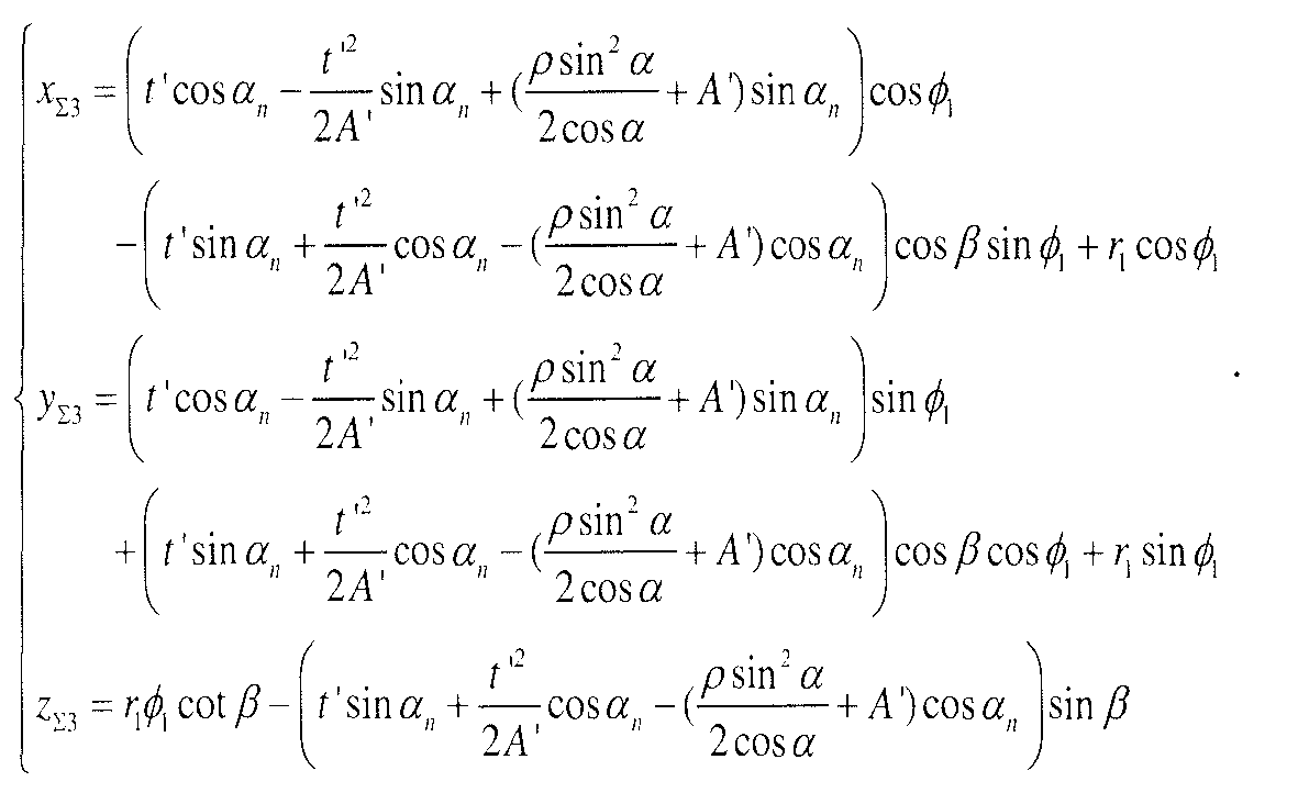
- Further, the tooth profile of the convex tooth gear includes a surface ∑1, a surface ∑2 and a surface Σ3 ; the tooth profile of the concave tooth gear includes a surface


- The equation of the surface ∑1 is:


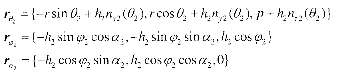
- The equation of ∑2 is:

- The equation of Σ3 is:


- The equation of


wherein h 1 is a radius of the tooth profile, n x1, n y1 and n z1 denote components of the normal vector of the tooth profile at corresponding contact point position, parameters ϕ 1 and α 1 denote general sphere L1 parameters respectively. - The equation of


- The equation of


- Further, the number of the contact points of the convex tooth gear and the concave tooth gear is 4, and the contact points are a contact point p1, a contact point p2, a contact point p3 and a contact point p4 respectively; three contact curves formed by the contact points on the tooth profile of the convex tooth gear or the concave tooth gear are a contact curve l 1, a contact curve l 2 and a contact curve l 3 respectively; the meshing point p1 is on the contact curve l 1, the meshing point p2 as well as the meshing point p3 are on the contact curve l 2, the contact point p4 is on the contact curve l 3; the contact curve l 2 is a quadric parabolic curve, both the contact curve l 1 and the contact curve l 3 are circular arc curves and arranged at two sides of the contact curve l 2.
- Further, the tooth profile of the convex tooth gear includes a surface ∑1 ; the tooth profile curved surface of the concave tooth gear includes a surface


- The equation of ∑1 is:


- The equation of


- The equation of


- The equation of


- Further, the number of the contact points of the convex tooth gear and the concave tooth gear is 5, the contact points are a contact point p1, a contact point p2, a contact point p3, a contact point p4, and a contact point p5 respectively; three contact curves formed by the contact points on the tooth profile of the convex tooth gear or the concave tooth gear are a contact curve l 1, a contact curve l 2 and a contact curve l 3 respectively; the contact point p1 as well as the contact point p2 are on the contact curve l 1, the meshing point p3 is on the contact curve l 2, the contact point p4 as well as the contact point p5 are on the contact curve l 3; the contact curve l 2 is a circular arc curve, both the contact curve l 1 and the contact curve l 3 are quadric parabolic curves and arranged at the two sides of l 2.
- Further, the tooth profile of the convex tooth gear includes a surface ∑1 ; the tooth profile of the concave tooth gear includes a surface


- The equation of Σ1 is:


- The equation of


- The equation of


- The equation of

- The advantageous effects of the present invention are: the meshing manner of the conjugate-curve-based multipoint-contact bevel gear pair is that the convex tooth gear and the concave tooth gear are simultaneously in multipoint contact and all the contact paths on respective tooth surfaces are smooth space curve. Such transmission inherits the meshing characteristics of conjugate curves, and the tooth profile of multipoint contact has high contact strength, large bearing capacity, a high transmission efficiency, a low lubricating oil temperature rise, a greatly decreased sliding rate, a small abrasion. Meanwhile, according to different requirements, different contact curves may be applied to achieve one-point, two-point or multipoint contact when gears mesh. These gears contribute to solves limitation where existing point contact gears, whose tooth surfaces are spherical tubular surfaces which are generated by the enveloping motions of a sphere whose center moves along a spatial curve, and have only one-point contact when they mesh. Therefore, the conjugate-curve-based multipoint-contact gear transmission is a kind of high performance gear transmission which has a broad prospect of application.
- Hereinafter, the present invention is further described in conjunction with drawings and embodiments:
-
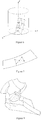
Figure 1 is a diagram of a tooth surface structure of a bevel gear which has three-point contact of the present invention; -
Figure 2 is a diagram of meshing of a bevel gear which has three-point contact of the present invention; -
Figure 3 is a diagram of derivation of a tooth profile of a bevel gear which has three-point contact of the present invention; -
Figure 4 is a diagram of a tooth surface structure of a bevel gear which has four-point contact of the present invention; -
Figure 5 is a diagram of meshing of a bevel gear which has four-point contact of the present invention; -
Figure 6 is a diagram of derivation of a tooth profile of a bevel gear which has four-point contact of the present invention; -
Figure 7 is a diagram of a tooth surface structure of a bevel gear which has five-point contact of the present invention; -
Figure 8 is a diagram of meshing of a bevel gear which has five-point contact of the present invention; -
Figure 9 is a diagram of derivation of a tooth profile of a bevel gear which has five-point contact of the present invention. - In an embodiment as shown in
Figures 1, 2 and3 , three-segment tooth profile curves which are circular arc curves are selected in different cross sections of a tooth, and an optimum pressure angle is determined to achieve a general distribution of three-point contact at different cross sections. As shown inFigures 1 and 2 , a convex meshing tubular tooth surface and a concave meshing tubular tooth surface are constructed based on a conjugate curve meshing theory to form a pairing meshing pair. The meshing pair moves along a contact point trace in an axial direction, both of them are generally of three-point contact in different cross sections of the tooth surface. - A circular helix is selected as a tooth surface conjugate contact curve. As shown in
Figure 3 , in a space coordinate system, l 1, l 2 and l 3 are three helical curves on a cylinder, the curve l 2 rotating around a center axis relative to the curve l 1 by an angle Δθ 1, the curve l 3 rotating around the center axis relative to the curve l 1 by an angle Δθ 2. - Assuming that the curvilinear equation of l 1 is

- The curve l 2 rotates around the center axis relative to the curve l 1 by the angle Δθ 1, and based on a coordinate transformation matrix, the curvilinear equation of the circular helix l 2 is obtained as

- Likewise, the curve l 3 rotates around the center axis relative to the curve l 1 by the angle Δθ 2, and based on a coordinate transformation matrix, the curvilinear equation of the circular helix l 3 is obtained as

- Motion traces of the three contact points on the tooth surface are circular helixes l 1, l 2 and l 3. Especially, it should be noted that the three contact points don't locate in the same cross section, namely they present a different cross section distribution. The tooth surface is mainly constructed by three surfaces.
- (1) The expression of the circular helix l 1 is known, and based on the tooth surface construction theory and method of meshing tubular, an equation of a surface ∑1 formed from l 1 may be obtained as


- (2) The expression of the circular helix l 2 is known, and based on the tooth surface construction theory and method of meshing tubular, an equation of a surface Σ2 formed from l 2 may be obtained as


- (3) The expression of the circular helix l 3 is known, and based on the tooth surface construction theory and method of meshing tubular, an equation of a surface Σ3 formed by from l 3 may be obtained as


- In another embodiment as shown
Figures 4, 5 and6 , three-segment tooth profile curves which are circular arc curves are selected in different cross sections of a tooth, the first and the last segments of tooth profile curves are arc curves, the middle tooth profile curve is a quadric parabolic curve, an optimum point contact pressure angle is determined to achieve local four-point symmetrical contact. As shown inFigure 5 , a convex meshing tubular tooth surface and a concave meshing tubular tooth surface are constructed based on a conjugate curve meshing theory to form a pairing meshing pair. the meshing pair moves along a contact point trace in an axial direction, both of them take on local four-point symmetrical contact in different cross sections of the tooth surface. - As shown in
Figure 6 , three-segment curves are selected on the tooth surface of the gear, wherein the first and the last segments of tooth profile curves are circular arc curves, the middle tooth profile curve is a quadric parabolic curve. In a process of meshing, the circular arc profile has single point contact within respective cross section region, the parabolic profile has two point contact within its cross section region, the meshing pair constitutes a four-point contact state. - The convex tooth surface adopts a circular arc profile, the general equation of its tooth surface can refer to the meshing tubular formation method, and it is further expressed as


- A concave tooth face is formed by three parts which include an arc profile c 1, a parabolic profile c 2 and an arc profile c 3.
- Assuming that the circular arc profile c 1 is expressed as

- The gear meshing theory kinematics method is adopted to derive the tooth surface equation, the equation of the tooth surface Σ1 which is formed by the normal arc profile c 1 and its helical motion is

- Assuming that the quadratic parabolic profile c 2 is expressed as

- Likewise, the equation of the tooth surface ∑2 which is formed by the quadratic parabolic profile and its helical motion is

- The derivation method of the tooth surface equation of the arc profile c 3 segment is the same as that of the arc profile c 1, assuming that the arc profile c 3 is expressed as

- The gear meshing theory kinematics method is adopted to derive the tooth surface equation, the equation of the tooth surface ∑3 which is formed by the normal arc profile c 3 and its helical motion is

- in the equation, ϕ 1 is a gear rotation angle, r 1 is a radius of a gear pitch circle, β is the helix angle of a gear. If the circle center of the tooth profile is located outside the pitch circle, X' is positive, and otherwise, X' is negative; if the circle center of the tooth profile is located at a different side along the tooth symmetry axis, L' is positive, and otherwise, L' is negative.
- Based on the above, when the two segments of arc profiles and the middle quadratic parabolic profile are distributed closely, it is possible to achieve local four-point symmetrical contact; when the two segments of arc profiles and the middle quadratic parabolic profile are distributed in the full tooth width direction, it is possible to achieve four-point symmetrical contact in the tooth width direction.
- In an embodiment as shown
Figures 7, 8 and9 , different segments of tooth profile curves are selected in different cross sections in the tooth width direction of the tooth surface, the first and the last segments of tooth profile curves are quadric parabolic curves, the middle tooth profile curve is a arc curve, an optimum pressure angle is determined to achieve symmetrical five-point contact in the tooth width direction. As shown inFigure 8 , a convex tubular meshing tooth surface and a concave tubular meshing tooth surface are constructed based on a conjugate curve meshing theory to form a pairing meshing pair. The meshing pair moves along a contact point trace in an axial direction, both of them are generally of five-point symmetrical contact in the tooth width direction. - As shown in
Figure 9 , three-segment curves are selected on the tooth surface, wherein the first and the last segments of tooth profile curves are quadric parabolic curves, the middle tooth profile curve is an arc curve. In a process of meshing, the arc profile has single point contact within respective cross section region and the parabolic profile has two point contact within its cross section region, so the meshing pair constitutes a five-point contact state. - The convex tooth face still adopts a circular arc profile, the equation of its tooth surface refers to the meshing tubular formation method, and it is expressed as
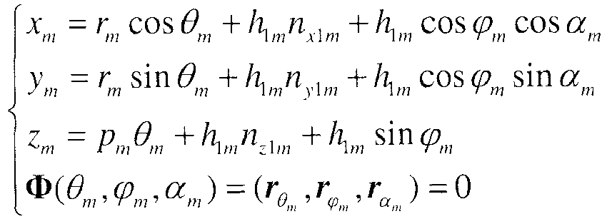

- A concave tooth face is formed by three parts which include a quadratic parabolic profile m 1, an arc profile m 2 and a quadratic parabolic profile m 3.
- Assuming that the quadratic parabolic profile m 1 is expressed as

- Likewise, the equation of the tooth surface ∑1 which is formed by the quadratic parabolic profile and its helical motion is:

- Assuming that the arc profile m 2 is expressed as

- The gear meshing theory kinematics method is adopted to derive the tooth surface equation, the equation of the tooth surface The gear meshing theory kinematics method is adopted to derive the tooth surface equation, the equation of the tooth surface ∑2 which is formed by the normal arc profile m 2 and its helical motion is

- Assuming that the quadratic parabolic profile m 3 is expressed as

- Likewise, the equation of the tooth surface ∑3 which is formed by the quadratic parabolic profile and its helical motion is

- Finally, it is to be explained that, the above embodiments are only used to explain the technical solutions of the present invention, but not to limit the present invention. Although the present invention is explained in detail with reference to preferred embodiments, those ordinary skilled in the art should understand that, without departing from the scope of the technical solutions of the present invention, modifications or equivalent substitutions may be made to the technical solutions of the present invention, which are to be covered by the scope of the claim of the present invention.
Claims (1)
- A conjugate-curve-based multipoint contact bevel gear meshing pair, comprising:a convex tooth gear and a concave tooth gear which are of point contact and have multiple contact points, wherein a meshing surface of the convex tooth gear and the concave tooth gear is a tubular surface,characterized in thatthe number of the contact points of the convex tooth gear and the concave tooth gear is 3 and the multiple contact points of the convex tooth gear and the concave tooth gear are distributed on different cross sections of tooth profiles,wherein: three contact curves formed by the contact points on the tooth surface of the convex tooth gear or the concave tooth gear are a contact curve l 1, a contact curve l 2 and a contact curve l 3 respectively;the equation of the contact curve l 1 is:
 wherein r is a radius of the circular helix l 1, θ 1 is a curve parameter of the circular helix l1, its value range is θ 1i ≤ θ 1 ≤ θ 1 o, p is a helix parameter of the circular helix;the equation of the contact curve l 2 is:
 wherein r is a radius of the circular helix l 1, θ 1 is a curve parameter of the circular helix l 1, its value range is θ 1i ≤ θ 1 ≤ θ 1 o, p is a helix parameter of the circular helix;the equation of the contact curve l 3 is:
 wherein r is a radius of the circular helix l 1, θ 1 is a curve parameter of the circular helix l 1, its value range is θ 1i ≤ θ 1 ≤ θ 1 o, p is a helix parameter of the circular helix,wherein: the tooth profile of the convex tooth gear includes a surface ∑1, a surface ∑2 and a surface ∑3; the tooth profile of the concave tooth gear includes a surface

 the equation of ∑1 is:
 in the equation,
 wherein h 1 is a radius of the tooth profile, n x1 , n y1 and n z1 denote components of the normal vector of the tooth profile at corresponding contact point position, parameters ϕ 1 and α 1 denote general sphere L1 parameters respectively;the equation of ∑2 is:
 in the equation,
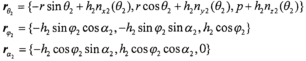 wherein h 2 is a radius of the tooth profile, n x2 , n y2 and n z2 denote components of the normal vector of the tooth profile at corresponding contact point position, parameters ϕ 2 and α 2 denote general sphere L2 parameters respectively;the equation of ∑3 is:
 in the equation,
 wherein h 3 is a radius of the tooth profile, n x3, n y3 and n z3 denote components of the normal vector of the tooth profile at corresponding contact point position, parameters ϕ 3 and α 3 denote general sphere L3 parameters respectively;the equation of
 in the equation,
 wherein h 1 is a radius of the tooth profile, n x1 , n y1 and n z1 denote components of the normal vector of the tooth profile at corresponding contact point position, parameters ϕ 1 and α 1 denote general sphere L1 parameters respectively;the equation of
 in the equation,
 wherein h 2 is a radius of the tooth profile curved surface, n x2 , ny2 and n z2 denote components of the normal vector of the tooth profile at corresponding contact point position, parameters ϕ 2 and α 2 denote general sphere L2 parameters respectively;the equation of
 in the equation,
 wherein h 3 is a radius of the tooth profile curved surface, n x3, n y3 and n z3 denote components of the normal vector of the tooth profile at corresponding contact point position, parameters ϕ 3 and α 3 denote general sphere L3 parameters respectively.
Applications Claiming Priority (2)
| Application Number | Priority Date | Filing Date | Title |
|---|---|---|---|
| CN201510579951.3A CN105202152B (en) | 2015-09-11 | 2015-09-11 | Multi-point contact bevel gear meshing pair based on conjugate curve |
| PCT/CN2016/072271 WO2017041416A1 (en) | 2015-09-11 | 2016-01-27 | Conjugate curve-based bevel gear meshing pair having multiple contact points |
Publications (3)
| Publication Number | Publication Date |
|---|---|
| EP3348868A1 EP3348868A1 (en) | 2018-07-18 |
| EP3348868A4 EP3348868A4 (en) | 2019-04-10 |
| EP3348868B1 true EP3348868B1 (en) | 2021-03-10 |
Family
ID=54950001
Family Applications (1)
| Application Number | Title | Priority Date | Filing Date |
|---|---|---|---|
| EP16843360.5A Active EP3348868B1 (en) | 2015-09-11 | 2016-01-27 | Conjugate curve-based bevel gear meshing pair having multiple contact points |
Country Status (3)
| Country | Link |
|---|---|
| EP (1) | EP3348868B1 (en) |
| CN (1) | CN105202152B (en) |
| WO (1) | WO2017041416A1 (en) |
Cited By (1)
| Publication number | Priority date | Publication date | Assignee | Title |
|---|---|---|---|---|
| US20240401670A1 (en) * | 2023-05-31 | 2024-12-05 | Chongqing University | Bevel Gear Pair With Constant Meshing Characteristics Constructed Tooth Pair |
Families Citing this family (5)
| Publication number | Priority date | Publication date | Assignee | Title |
|---|---|---|---|---|
| CN109446666B (en) * | 2018-10-31 | 2022-09-20 | 长安大学 | Design method of concave-convex tooth line coupler |
| CN109446667B (en) * | 2018-10-31 | 2022-09-16 | 长安大学 | Method for calculating dynamic backlash of helical bevel gear pair |
| CN110633549B (en) * | 2019-09-27 | 2023-01-03 | 北京工业大学 | Method for forming curved surface of stator of planar cylindrical pump |
| CN111219473B (en) * | 2020-03-12 | 2021-03-30 | 长安大学 | A Design Method of Spiral Bevel Gears with Large Coincidence |
| CN111853158B (en) * | 2020-07-14 | 2022-10-04 | 三峡大学 | Conical internal meshing line gear mechanism, construction method thereof and simulation verification method |
Family Cites Families (8)
| Publication number | Priority date | Publication date | Assignee | Title |
|---|---|---|---|---|
| US6101892A (en) * | 1997-04-10 | 2000-08-15 | Genesis Partners, L.P. | Gear form constructions |
| SI22871A (en) * | 2008-09-17 | 2010-03-31 | Gorazd@Hlebanja | Slant-toothed cylinder-shaped gearwheel pair for uniform power transmission |
| US20100212444A1 (en) * | 2009-02-23 | 2010-08-26 | Thomas David Smith | Conjugate roller drive |
| CN101975264B (en) * | 2010-10-15 | 2012-07-11 | 重庆大学 | Involute arc tooth profile bevel gear and meshing pair thereof |
| CN102853054B (en) * | 2012-09-27 | 2015-03-04 | 重庆大学 | Curve conjugation based symmetrical cambered surface conjugate curve gears and engagement pair thereof |
| CN103075493B (en) * | 2012-12-29 | 2015-07-15 | 重庆大学 | Bevel gear based on conjugate curves and meshing pair thereof |
| CN103939575B (en) * | 2014-04-10 | 2016-05-11 | 重庆大学 | Point contact gear, Meshing Pair and process tool thereof based on conjugate curves |
| CN104595422B (en) * | 2015-02-02 | 2017-02-01 | 中国地质大学(武汉) | Spiral-arc gear mechanism for parallel-shaft external-engaged transmission |
-
2015
- 2015-09-11 CN CN201510579951.3A patent/CN105202152B/en active Active
-
2016
- 2016-01-27 EP EP16843360.5A patent/EP3348868B1/en active Active
- 2016-01-27 WO PCT/CN2016/072271 patent/WO2017041416A1/en not_active Ceased
Non-Patent Citations (1)
| Title |
|---|
| None * |
Cited By (2)
| Publication number | Priority date | Publication date | Assignee | Title |
|---|---|---|---|---|
| US20240401670A1 (en) * | 2023-05-31 | 2024-12-05 | Chongqing University | Bevel Gear Pair With Constant Meshing Characteristics Constructed Tooth Pair |
| US12618455B2 (en) * | 2023-05-31 | 2026-05-05 | Chongqing University | Bevel gear pair with constant meshing characteristics constructed tooth pair |
Also Published As
| Publication number | Publication date |
|---|---|
| EP3348868A4 (en) | 2019-04-10 |
| WO2017041416A1 (en) | 2017-03-16 |
| CN105202152B (en) | 2019-04-02 |
| CN105202152A (en) | 2015-12-30 |
| EP3348868A1 (en) | 2018-07-18 |
Similar Documents
| Publication | Publication Date | Title |
|---|---|---|
| EP3348869B1 (en) | Conjugate curve-based cylindrical gear meshing pair having multiple contact points | |
| EP3130822B1 (en) | Point contact gear based on conjugate curves, meshing pair and machining tool therefor | |
| EP3348868A1 (en) | Conjugate curve-based bevel gear meshing pair having multiple contact points | |
| CN102853054B (en) | Curve conjugation based symmetrical cambered surface conjugate curve gears and engagement pair thereof | |
| EP2784350B1 (en) | Roller screw | |
| CN103075493B (en) | Bevel gear based on conjugate curves and meshing pair thereof | |
| US9267587B2 (en) | Roller screw | |
| EP3306132B1 (en) | Strain wave gearing device with compound meshing that involves congruity of tooth surfaces | |
| WO2017215621A1 (en) | Tooth profile design method for three-dimensional high-rigidity harmonic speed reducer | |
| US10550914B2 (en) | Concave-convex arc line gear mechanism for parallel shaft transmission | |
| US20170159789A1 (en) | Strain wave gearing having continuous-contact tooth profile formed using arcuate tooth profile | |
| CN110273979B (en) | Three-freedom-degree ball gear transmission pair | |
| CN105114542A (en) | Planetary gear transmission device based on conjugate curve herringbone gear | |
| CN103573921B (en) | A kind of involute spherical gear transmission pair | |
| CN110802280A (en) | A design method of involute spiral bevel gear tooth surface | |
| CN112377595B (en) | Internal engagement bevel gear pair based on space conjugate curve | |
| WO2023184652A1 (en) | Non-orthogonal elliptical toroidal worm gear pair | |
| CN104133940B (en) | Design method of point contact biparabolic gear | |
| CN103089920A (en) | Pure rolling gear mechanism | |
| Liang et al. | Calculation method of sliding ratios for conjugate-curve gear pair and its application | |
| KR20120037444A (en) | Toothed gears with tooth profile having different profile angles and differential with these toothed gears | |
| JP7477655B2 (en) | Gear Pair | |
| JP7529922B2 (en) | Gear Pair | |
| Kapelevich et al. | Root fillet optimization of thin rim planet gears with asymmetric teeth | |
| US12618455B2 (en) | Bevel gear pair with constant meshing characteristics constructed tooth pair |
Legal Events
| Date | Code | Title | Description |
|---|---|---|---|
| STAA | Information on the status of an ep patent application or granted ep patent |
Free format text: STATUS: THE INTERNATIONAL PUBLICATION HAS BEEN MADE |
|
| PUAI | Public reference made under article 153(3) epc to a published international application that has entered the european phase |
Free format text: ORIGINAL CODE: 0009012 |
|
| STAA | Information on the status of an ep patent application or granted ep patent |
Free format text: STATUS: REQUEST FOR EXAMINATION WAS MADE |
|
| 17P | Request for examination filed |
Effective date: 20180301 |
|
| AK | Designated contracting states |
Kind code of ref document: A1 Designated state(s): AL AT BE BG CH CY CZ DE DK EE ES FI FR GB GR HR HU IE IS IT LI LT LU LV MC MK MT NL NO PL PT RO RS SE SI SK SM TR |
|
| AX | Request for extension of the european patent |
Extension state: BA ME |
|
| DAV | Request for validation of the european patent (deleted) | ||
| DAX | Request for extension of the european patent (deleted) | ||
| A4 | Supplementary search report drawn up and despatched |
Effective date: 20190314 |
|
| RIC1 | Information provided on ipc code assigned before grant |
Ipc: F16H 55/17 20060101ALI20190307BHEP Ipc: F16H 55/08 20060101AFI20190307BHEP |
|
| STAA | Information on the status of an ep patent application or granted ep patent |
Free format text: STATUS: EXAMINATION IS IN PROGRESS |
|
| 17Q | First examination report despatched |
Effective date: 20200310 |
|
| GRAP | Despatch of communication of intention to grant a patent |
Free format text: ORIGINAL CODE: EPIDOSNIGR1 |
|
| STAA | Information on the status of an ep patent application or granted ep patent |
Free format text: STATUS: GRANT OF PATENT IS INTENDED |
|
| INTG | Intention to grant announced |
Effective date: 20201013 |
|
| GRAS | Grant fee paid |
Free format text: ORIGINAL CODE: EPIDOSNIGR3 |
|
| GRAA | (expected) grant |
Free format text: ORIGINAL CODE: 0009210 |
|
| STAA | Information on the status of an ep patent application or granted ep patent |
Free format text: STATUS: THE PATENT HAS BEEN GRANTED |
|
| AK | Designated contracting states |
Kind code of ref document: B1 Designated state(s): AL AT BE BG CH CY CZ DE DK EE ES FI FR GB GR HR HU IE IS IT LI LT LU LV MC MK MT NL NO PL PT RO RS SE SI SK SM TR |
|
| REG | Reference to a national code |
Ref country code: GB Ref legal event code: FG4D |
|
| REG | Reference to a national code |
Ref country code: AT Ref legal event code: REF Ref document number: 1370153 Country of ref document: AT Kind code of ref document: T Effective date: 20210315 Ref country code: CH Ref legal event code: EP |
|
| REG | Reference to a national code |
Ref country code: IE Ref legal event code: FG4D |
|
| REG | Reference to a national code |
Ref country code: DE Ref legal event code: R096 Ref document number: 602016054183 Country of ref document: DE |
|
| REG | Reference to a national code |
Ref country code: LT Ref legal event code: MG9D |
|
| PG25 | Lapsed in a contracting state [announced via postgrant information from national office to epo] |
Ref country code: BG Free format text: LAPSE BECAUSE OF FAILURE TO SUBMIT A TRANSLATION OF THE DESCRIPTION OR TO PAY THE FEE WITHIN THE PRESCRIBED TIME-LIMIT Effective date: 20210610 Ref country code: LT Free format text: LAPSE BECAUSE OF FAILURE TO SUBMIT A TRANSLATION OF THE DESCRIPTION OR TO PAY THE FEE WITHIN THE PRESCRIBED TIME-LIMIT Effective date: 20210310 Ref country code: NO Free format text: LAPSE BECAUSE OF FAILURE TO SUBMIT A TRANSLATION OF THE DESCRIPTION OR TO PAY THE FEE WITHIN THE PRESCRIBED TIME-LIMIT Effective date: 20210610 Ref country code: HR Free format text: LAPSE BECAUSE OF FAILURE TO SUBMIT A TRANSLATION OF THE DESCRIPTION OR TO PAY THE FEE WITHIN THE PRESCRIBED TIME-LIMIT Effective date: 20210310 Ref country code: FI Free format text: LAPSE BECAUSE OF FAILURE TO SUBMIT A TRANSLATION OF THE DESCRIPTION OR TO PAY THE FEE WITHIN THE PRESCRIBED TIME-LIMIT Effective date: 20210310 Ref country code: GR Free format text: LAPSE BECAUSE OF FAILURE TO SUBMIT A TRANSLATION OF THE DESCRIPTION OR TO PAY THE FEE WITHIN THE PRESCRIBED TIME-LIMIT Effective date: 20210611 |
|
| REG | Reference to a national code |
Ref country code: AT Ref legal event code: MK05 Ref document number: 1370153 Country of ref document: AT Kind code of ref document: T Effective date: 20210310 |
|
| REG | Reference to a national code |
Ref country code: NL Ref legal event code: MP Effective date: 20210310 |
|
| PG25 | Lapsed in a contracting state [announced via postgrant information from national office to epo] |
Ref country code: SE Free format text: LAPSE BECAUSE OF FAILURE TO SUBMIT A TRANSLATION OF THE DESCRIPTION OR TO PAY THE FEE WITHIN THE PRESCRIBED TIME-LIMIT Effective date: 20210310 Ref country code: LV Free format text: LAPSE BECAUSE OF FAILURE TO SUBMIT A TRANSLATION OF THE DESCRIPTION OR TO PAY THE FEE WITHIN THE PRESCRIBED TIME-LIMIT Effective date: 20210310 Ref country code: RS Free format text: LAPSE BECAUSE OF FAILURE TO SUBMIT A TRANSLATION OF THE DESCRIPTION OR TO PAY THE FEE WITHIN THE PRESCRIBED TIME-LIMIT Effective date: 20210310 |
|
| PG25 | Lapsed in a contracting state [announced via postgrant information from national office to epo] |
Ref country code: NL Free format text: LAPSE BECAUSE OF FAILURE TO SUBMIT A TRANSLATION OF THE DESCRIPTION OR TO PAY THE FEE WITHIN THE PRESCRIBED TIME-LIMIT Effective date: 20210310 |
|
| PG25 | Lapsed in a contracting state [announced via postgrant information from national office to epo] |
Ref country code: SM Free format text: LAPSE BECAUSE OF FAILURE TO SUBMIT A TRANSLATION OF THE DESCRIPTION OR TO PAY THE FEE WITHIN THE PRESCRIBED TIME-LIMIT Effective date: 20210310 Ref country code: AT Free format text: LAPSE BECAUSE OF FAILURE TO SUBMIT A TRANSLATION OF THE DESCRIPTION OR TO PAY THE FEE WITHIN THE PRESCRIBED TIME-LIMIT Effective date: 20210310 Ref country code: CZ Free format text: LAPSE BECAUSE OF FAILURE TO SUBMIT A TRANSLATION OF THE DESCRIPTION OR TO PAY THE FEE WITHIN THE PRESCRIBED TIME-LIMIT Effective date: 20210310 Ref country code: EE Free format text: LAPSE BECAUSE OF FAILURE TO SUBMIT A TRANSLATION OF THE DESCRIPTION OR TO PAY THE FEE WITHIN THE PRESCRIBED TIME-LIMIT Effective date: 20210310 |
|
| PG25 | Lapsed in a contracting state [announced via postgrant information from national office to epo] |
Ref country code: SK Free format text: LAPSE BECAUSE OF FAILURE TO SUBMIT A TRANSLATION OF THE DESCRIPTION OR TO PAY THE FEE WITHIN THE PRESCRIBED TIME-LIMIT Effective date: 20210310 Ref country code: RO Free format text: LAPSE BECAUSE OF FAILURE TO SUBMIT A TRANSLATION OF THE DESCRIPTION OR TO PAY THE FEE WITHIN THE PRESCRIBED TIME-LIMIT Effective date: 20210310 Ref country code: PL Free format text: LAPSE BECAUSE OF FAILURE TO SUBMIT A TRANSLATION OF THE DESCRIPTION OR TO PAY THE FEE WITHIN THE PRESCRIBED TIME-LIMIT Effective date: 20210310 Ref country code: PT Free format text: LAPSE BECAUSE OF FAILURE TO SUBMIT A TRANSLATION OF THE DESCRIPTION OR TO PAY THE FEE WITHIN THE PRESCRIBED TIME-LIMIT Effective date: 20210712 Ref country code: IS Free format text: LAPSE BECAUSE OF FAILURE TO SUBMIT A TRANSLATION OF THE DESCRIPTION OR TO PAY THE FEE WITHIN THE PRESCRIBED TIME-LIMIT Effective date: 20210710 |
|
| REG | Reference to a national code |
Ref country code: DE Ref legal event code: R097 Ref document number: 602016054183 Country of ref document: DE |
|
| PLBE | No opposition filed within time limit |
Free format text: ORIGINAL CODE: 0009261 |
|
| STAA | Information on the status of an ep patent application or granted ep patent |
Free format text: STATUS: NO OPPOSITION FILED WITHIN TIME LIMIT |
|
| PG25 | Lapsed in a contracting state [announced via postgrant information from national office to epo] |
Ref country code: ES Free format text: LAPSE BECAUSE OF FAILURE TO SUBMIT A TRANSLATION OF THE DESCRIPTION OR TO PAY THE FEE WITHIN THE PRESCRIBED TIME-LIMIT Effective date: 20210310 Ref country code: AL Free format text: LAPSE BECAUSE OF FAILURE TO SUBMIT A TRANSLATION OF THE DESCRIPTION OR TO PAY THE FEE WITHIN THE PRESCRIBED TIME-LIMIT Effective date: 20210310 Ref country code: DK Free format text: LAPSE BECAUSE OF FAILURE TO SUBMIT A TRANSLATION OF THE DESCRIPTION OR TO PAY THE FEE WITHIN THE PRESCRIBED TIME-LIMIT Effective date: 20210310 |
|
| 26N | No opposition filed |
Effective date: 20211213 |
|
| PG25 | Lapsed in a contracting state [announced via postgrant information from national office to epo] |
Ref country code: SI Free format text: LAPSE BECAUSE OF FAILURE TO SUBMIT A TRANSLATION OF THE DESCRIPTION OR TO PAY THE FEE WITHIN THE PRESCRIBED TIME-LIMIT Effective date: 20210310 |
|
| PG25 | Lapsed in a contracting state [announced via postgrant information from national office to epo] |
Ref country code: IT Free format text: LAPSE BECAUSE OF FAILURE TO SUBMIT A TRANSLATION OF THE DESCRIPTION OR TO PAY THE FEE WITHIN THE PRESCRIBED TIME-LIMIT Effective date: 20210310 |
|
| PG25 | Lapsed in a contracting state [announced via postgrant information from national office to epo] |
Ref country code: IS Free format text: LAPSE BECAUSE OF FAILURE TO SUBMIT A TRANSLATION OF THE DESCRIPTION OR TO PAY THE FEE WITHIN THE PRESCRIBED TIME-LIMIT Effective date: 20210710 |
|
| PG25 | Lapsed in a contracting state [announced via postgrant information from national office to epo] |
Ref country code: MC Free format text: LAPSE BECAUSE OF FAILURE TO SUBMIT A TRANSLATION OF THE DESCRIPTION OR TO PAY THE FEE WITHIN THE PRESCRIBED TIME-LIMIT Effective date: 20210310 |
|
| REG | Reference to a national code |
Ref country code: CH Ref legal event code: PL |
|
| GBPC | Gb: european patent ceased through non-payment of renewal fee |
Effective date: 20220127 |
|
| REG | Reference to a national code |
Ref country code: BE Ref legal event code: MM Effective date: 20220131 |
|
| PG25 | Lapsed in a contracting state [announced via postgrant information from national office to epo] |
Ref country code: LU Free format text: LAPSE BECAUSE OF NON-PAYMENT OF DUE FEES Effective date: 20220127 Ref country code: GB Free format text: LAPSE BECAUSE OF NON-PAYMENT OF DUE FEES Effective date: 20220127 |
|
| PG25 | Lapsed in a contracting state [announced via postgrant information from national office to epo] |
Ref country code: FR Free format text: LAPSE BECAUSE OF NON-PAYMENT OF DUE FEES Effective date: 20220131 Ref country code: BE Free format text: LAPSE BECAUSE OF NON-PAYMENT OF DUE FEES Effective date: 20220131 |
|
| PG25 | Lapsed in a contracting state [announced via postgrant information from national office to epo] |
Ref country code: LI Free format text: LAPSE BECAUSE OF NON-PAYMENT OF DUE FEES Effective date: 20220131 Ref country code: CH Free format text: LAPSE BECAUSE OF NON-PAYMENT OF DUE FEES Effective date: 20220131 |
|
| PG25 | Lapsed in a contracting state [announced via postgrant information from national office to epo] |
Ref country code: IE Free format text: LAPSE BECAUSE OF NON-PAYMENT OF DUE FEES Effective date: 20220127 |
|
| PG25 | Lapsed in a contracting state [announced via postgrant information from national office to epo] |
Ref country code: HU Free format text: LAPSE BECAUSE OF FAILURE TO SUBMIT A TRANSLATION OF THE DESCRIPTION OR TO PAY THE FEE WITHIN THE PRESCRIBED TIME-LIMIT; INVALID AB INITIO Effective date: 20160127 |
|
| PG25 | Lapsed in a contracting state [announced via postgrant information from national office to epo] |
Ref country code: MK Free format text: LAPSE BECAUSE OF FAILURE TO SUBMIT A TRANSLATION OF THE DESCRIPTION OR TO PAY THE FEE WITHIN THE PRESCRIBED TIME-LIMIT Effective date: 20210310 Ref country code: CY Free format text: LAPSE BECAUSE OF FAILURE TO SUBMIT A TRANSLATION OF THE DESCRIPTION OR TO PAY THE FEE WITHIN THE PRESCRIBED TIME-LIMIT Effective date: 20210310 |
|
| PG25 | Lapsed in a contracting state [announced via postgrant information from national office to epo] |
Ref country code: MT Free format text: LAPSE BECAUSE OF FAILURE TO SUBMIT A TRANSLATION OF THE DESCRIPTION OR TO PAY THE FEE WITHIN THE PRESCRIBED TIME-LIMIT Effective date: 20210310 |
|
| PG25 | Lapsed in a contracting state [announced via postgrant information from national office to epo] |
Ref country code: TR Free format text: LAPSE BECAUSE OF FAILURE TO SUBMIT A TRANSLATION OF THE DESCRIPTION OR TO PAY THE FEE WITHIN THE PRESCRIBED TIME-LIMIT Effective date: 20210310 |
|
| PGFP | Annual fee paid to national office [announced via postgrant information from national office to epo] |
Ref country code: DE Payment date: 20260122 Year of fee payment: 11 |