EP3348838A1 - Vane pump - Google Patents
Vane pump Download PDFInfo
- Publication number
- EP3348838A1 EP3348838A1 EP16844253.1A EP16844253A EP3348838A1 EP 3348838 A1 EP3348838 A1 EP 3348838A1 EP 16844253 A EP16844253 A EP 16844253A EP 3348838 A1 EP3348838 A1 EP 3348838A1
- Authority
- EP
- European Patent Office
- Prior art keywords
- pressure chamber
- discharge port
- pump
- passage
- pressure
- Prior art date
- Legal status (The legal status is an assumption and is not a legal conclusion. Google has not performed a legal analysis and makes no representation as to the accuracy of the status listed.)
- Withdrawn
Links
Images
Classifications
-
- F—MECHANICAL ENGINEERING; LIGHTING; HEATING; WEAPONS; BLASTING
- F04—POSITIVE - DISPLACEMENT MACHINES FOR LIQUIDS; PUMPS FOR LIQUIDS OR ELASTIC FLUIDS
- F04C—ROTARY-PISTON, OR OSCILLATING-PISTON, POSITIVE-DISPLACEMENT MACHINES FOR LIQUIDS; ROTARY-PISTON, OR OSCILLATING-PISTON, POSITIVE-DISPLACEMENT PUMPS
- F04C15/00—Component parts, details or accessories of machines, pumps or pumping installations, not provided for in groups F04C2/00 - F04C14/00
- F04C15/06—Arrangements for admission or discharge of the working fluid, e.g. constructional features of the inlet or outlet
-
- F—MECHANICAL ENGINEERING; LIGHTING; HEATING; WEAPONS; BLASTING
- F04—POSITIVE - DISPLACEMENT MACHINES FOR LIQUIDS; PUMPS FOR LIQUIDS OR ELASTIC FLUIDS
- F04C—ROTARY-PISTON, OR OSCILLATING-PISTON, POSITIVE-DISPLACEMENT MACHINES FOR LIQUIDS; ROTARY-PISTON, OR OSCILLATING-PISTON, POSITIVE-DISPLACEMENT PUMPS
- F04C2/00—Rotary-piston machines or pumps
- F04C2/30—Rotary-piston machines or pumps having the characteristics covered by two or more groups F04C2/02, F04C2/08, F04C2/22, F04C2/24 or having the characteristics covered by one of these groups together with some other type of movement between co-operating members
- F04C2/34—Rotary-piston machines or pumps having the characteristics covered by two or more groups F04C2/02, F04C2/08, F04C2/22, F04C2/24 or having the characteristics covered by one of these groups together with some other type of movement between co-operating members having the movement defined in groups F04C2/08 or F04C2/22 and relative reciprocation between the co-operating members
- F04C2/344—Rotary-piston machines or pumps having the characteristics covered by two or more groups F04C2/02, F04C2/08, F04C2/22, F04C2/24 or having the characteristics covered by one of these groups together with some other type of movement between co-operating members having the movement defined in groups F04C2/08 or F04C2/22 and relative reciprocation between the co-operating members with vanes reciprocating with respect to the inner member
-
- F—MECHANICAL ENGINEERING; LIGHTING; HEATING; WEAPONS; BLASTING
- F01—MACHINES OR ENGINES IN GENERAL; ENGINE PLANTS IN GENERAL; STEAM ENGINES
- F01C—ROTARY-PISTON OR OSCILLATING-PISTON MACHINES OR ENGINES
- F01C21/00—Component parts, details or accessories not provided for in groups F01C1/00 - F01C20/00
- F01C21/10—Outer members for co-operation with rotary pistons; Casings
- F01C21/104—Stators; Members defining the outer boundaries of the working chamber
- F01C21/108—Stators; Members defining the outer boundaries of the working chamber with an axial surface, e.g. side plates
-
- F—MECHANICAL ENGINEERING; LIGHTING; HEATING; WEAPONS; BLASTING
- F04—POSITIVE - DISPLACEMENT MACHINES FOR LIQUIDS; PUMPS FOR LIQUIDS OR ELASTIC FLUIDS
- F04C—ROTARY-PISTON, OR OSCILLATING-PISTON, POSITIVE-DISPLACEMENT MACHINES FOR LIQUIDS; ROTARY-PISTON, OR OSCILLATING-PISTON, POSITIVE-DISPLACEMENT PUMPS
- F04C15/00—Component parts, details or accessories of machines, pumps or pumping installations, not provided for in groups F04C2/00 - F04C14/00
Definitions
- the present invention relates to a vane pump.
- JP2002-161869A discloses a balanced vane pump having two discharge ports at symmetrical positions. Discharged oil discharged from these two discharge ports flows through an annular pressure chamber provided in a housing and flows into a flow passage connected to a flow-amount control valve.
- the present invention has been conceived in light of the problems mentioned above, and an object thereof is to reduce the size of a vane pump.
- a vane pump includes: a rotor linked to a driving shaft and having a plurality of vanes on an outer circumference thereof; a cam ring configured to accommodate the rotor and define pump chambers in a space therein; a pump body provided with a pump-accommodating concave portion into which the rotor and the cam ring are accommodated; a side plate provided between the rotor and the pump body; a plurality of discharge ports formed in the side plate and configured to discharge working fluid from the pump chambers; a high-pressure chamber in a form of a groove formed in a bottom portion of the pump-accommodating concave portion, the working fluid discharged from the plurality of discharge ports being led to the high-pressure chamber; and a high-pressure passage having an opening portion opening to the high-pressure chamber, the high-pressure passage being configured to guide the working fluid to outside of the high-pressure chamber, wherein one of the plurality of discharge ports is arranged so as to face the opening portion
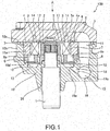
- FIG. 1 is a sectional view showing a cross section of the vane pump 100, cut in parallel to a driving shaft.
- the vane pump 100 is used as a fluid pressure source for a fluid pressure apparatus mounted on a vehicle, such as, for example, a power steering apparatus, a transmission, or the like. Oil, aqueous alternative fluid of other types, or the like may be used as working fluid.
- the vane pump 100 includes a plurality of vanes 3 provided in the rotor 2 so as to be capable of reciprocating in the radial direction of the rotor 2, and a cam ring 4 that accommodates the rotor 2 therein such that tip-end portions of the vanes 3 slide on a cam face 4a on the inner circumference of the cam ring 4 by rotation of the rotor 2.
- slits having openings on an outer circumferential surface of the rotor 2 are formed in a radiating pattern with predetermined gaps therebetween, and the vanes 3 are respectively inserted into the slits in a freely slidable manner.
- back pressure chambers 17 into which discharge pressure of the pump is guided are defined.
- the vanes 3 are pushed by the pressure in the back pressure chambers 17 in the directions in which the vanes 3 are drawn out from the slits, and the tip-end portions of the vanes 3 are brought into contact with the cam face 4a on the inner circumference of the cam ring 4.
- a plurality of pump chambers 7 are defined in the cam ring 4 by the outer surface of the rotor 2, the cam face 4a of the cam ring 4, and the adjacent vanes 3.
- the cam ring 4 is an annular member of which the cam face 4a on the inner circumference has an oval shape, and the cam ring 4 has suction regions in which volumes of the pump chambers 7 partitioned by and between the respective vanes 3, which slide on the cam face 4a by the rotation of the rotor 2, are expanded and discharge regions in which volumes of the pump chambers 7 are contracted.
- the respective pump chambers 7 are expanded/contracted by the rotation of the rotor 2.
- the vane pump 100 is a so-called balanced vane pump in which the cam ring 4 has two suction regions and two discharge regions.
- a pump cover 5 is arranged so as to be in contact with one side surfaces of the rotor 2 and the cam ring 4 on the one side (upper side in FIG. 1 ), and a side plate 6 is arranged so as to be in contact with the other side surfaces of the rotor 2 and the cam ring 4 on the other side (lower side in FIG. 1 ).
- the pump cover 5 and the side plate 6 are arranged in such a manner that both side surfaces of the rotor 2 and the cam ring 4 are sandwiched, and thereby, the pump chambers 7 are sealed.
- two arc-shaped suction ports 8 that open so as to correspond to the suction regions of the cam ring 4 and that guide working oil as the working fluid to the pump chambers 7 are formed so as to form grooves.
- a pair of an arc-shaped first discharge port 9a and an arc-shaped second discharge port 9b are formed so as to penetrate through the side plate 6.
- the first discharge port 9a and the second discharge port 9b are formed so as to open correspondingly to the discharge regions of the cam ring 4 and discharge the working oil that has been discharged from the pump chambers 7 to a high-pressure chamber 12.
- the respective pump chambers 7 suck the working oil through the suction ports 8 in the suction regions of the cam ring 4 and discharge the working oil through the first discharge port 9a and the second discharge port 9b in the discharge regions of the cam ring 4.
- the respective pump chambers 7 supply/discharge the working oil by the expansion/contraction due to the rotation of the rotor 2.
- the driving shaft 1 is rotatably supported by a pump body 10 via a bush 26.
- a pump-accommodating concave portion 10a for accommodating the rotor 2, the cam ring 4, and the side plate 6 is formed in the pump body 10.
- An annular groove portion 15 is formed in a bottom portion of the pump-accommodating concave portion 10a.
- the side plate 6 is arranged on the bottom portion of the pump-accommodating concave portion 10a, and the annular high-pressure chamber 12 is defined by the groove portion 15 and the side plate 6.
- the working oil that has been discharged from the pump chambers 7 through the first discharge port 9a and the second discharge port 9b is guided into the high-pressure chamber 12.
- the driving shaft 1 penetrates through the side plate 6.
- the cam ring 4 is accommodated in the pump-accommodating concave portion 10a so as to be stacked on the side plate 6.
- the pump cover 5 is fastened to an end surface 10c of an annular skirt 10b of the pump body 10, and thereby, the pump-accommodating concave portion 10a is sealed by the pump cover 5.
- the side plate 6 is provided with two positioning pins 14 that penetrate through concave portions (not shown) formed on an outer circumferential surface of the cam ring 4 and inserted into pin holes 5a of the pump cover 5. With the positioning pins 14, relative rotation of the pump cover 5 and the side plate 6 with respect to the cam ring 4 is restricted, thereby achieving positioning of the suction ports 8 of the pump cover 5 to the suction regions of the cam ring 4 and positioning of the first discharge port 9a and the second discharge port 9b of the side plate 6 to the discharge regions of the cam ring 4.
- a suction passage 11 that communicates with the suction ports 8 and guides the working oil to the suction ports 8 and a discharge passage 13 that communicates with the high-pressure chamber 12 and supplies the working oil in the high-pressure chamber 12 to an external hydraulic apparatus through a high-pressure passage 19 are formed.
- a flow-amount control valve 20 (see FIG. 2 ) for controlling the flow amount of the working oil supplied to the hydraulic apparatus is interposed in the discharge passage 13.
- the flow-amount control valve 20 is accommodated in an assembly hole 18 formed in the pump body 10.
- the working oil in the high-pressure chamber 12 is guided to the flow-amount control valve 20 through the high-pressure passage 19 formed in the pump body 10.
- the high-pressure passage 19 has an opening portion 19a that opens to the high-pressure chamber 12 and an exit portion 19b that opens to the assembly hole 18.
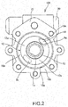
- FIG. 2 is a plan view of the pump body 10 viewed from the direction of an arrow A in FIG. 1 , and is a diagram showing a state in which the pump-accommodating concave portion 10a is empty.
- the annular groove portion 15 is formed so as to surround the periphery of an insert hole 1a into which the driving shaft 1 is inserted.
- the groove portion 15 may be formed in an arc shape.
- the side plate 6 is mounted on an annular step portion 10d forming an outer edge of the bottom portion of the pump-accommodating concave portion 10a, thereby sealing the groove portion 15 and defining the high-pressure chamber 12.
- the first discharge port 9a and the second discharge port 9b of the side plate 6 open to the high-pressure chamber 12 and guide the working oil that has been discharged from the pump chambers 7 to the high-pressure chamber 12.
- the first discharge port 9a and the second discharge port 9b are formed so as to face each other with the driving shaft 1 located therebetween.
- the working oil that has been guided to the high-pressure chamber 12 through the first discharge port 9a and the second discharge port 9b flows into the high-pressure passage 19 from the opening portion 19a.
- the first discharge port 9a is arranged so as to face the opening portion 19a of the high-pressure passage 19.
- the working oil that has been guided from the first discharge port 9a to the high-pressure chamber 12 crosses the high-pressure chamber 12 and flows directly into the high-pressure passage 19.
- the second discharge port 9b is arranged at a position remote from the opening portion 19a of the high-pressure passage 19.
- the flow of the working oil that has been guided from the second discharge port 9b to the high-pressure chamber 12 is divided into two flows flowing into a first high-pressure chamber 12a and a second high-pressure chamber 12b, through which the second discharge port 9b is communicated with the opening portion 19a of the high-pressure passage 19 along the circumferential direction at the left side and the right side in FIG. 2 , respectively.
- the flows of the working oil in the first high-pressure chamber 12a and the second high-pressure chamber 12b are mixed at the opening portion 19a of the high-pressure passage 19, and the mixed flow flows into the high-pressure passage 19.
- the high-pressure chamber 12 is formed in an arc shape, in other words, for example, in a case in which the high-pressure chamber 12 is constituted of the first high-pressure chamber 12a only, it suffices to ensure that the flow-passage cross-sectional area of the high-pressure chamber 12 (the first high-pressure chamber 12a) is greater than the flow-passage cross-sectional area of the second discharge port 9b.
- the first discharge port 9a is arranged so as to face the opening portion 19a of the high-pressure passage 19.
- the high-pressure chamber 12 is formed in an annular shape
- the working oil that has been guided from the second discharge port 9b to the high-pressure chamber 12 flows by being divided into two flows flowing into the first high-pressure chamber 12a and the second high-pressure chamber 12b, as compared with a case in which the high-pressure chamber 12 is formed in the arc shape (a case in which only the first high-pressure chamber 12a is formed)
- the vane pump 100 includes the rotor 2 that is linked to the driving shaft 1 and has the plurality of vanes 3 on the outer circumference thereof, the cam ring 4 that accommodates the rotor 2 and defines the pump chambers 7 in a space therein, the pump body 10 that is provided with the pump-accommodating concave portion 10a into which the rotor 2 and the cam ring 4 are accommodated, the side plate 6 that is provided between the rotor 2 and the pump body 10, a plurality of discharge ports (the first discharge port 9a and the second discharge port 9b) that are formed in the side plate 6 and discharge the working fluid from the pump chambers 7, the high-pressure chamber 12 that is formed in a form of a groove in the bottom portion of the pump-accommodating concave portion 10a, the working fluid is discharged from the plurality of discharge ports (the first discharge port 9a and the second discharge port 9b) being led to the high-pressure chamber 12, and the high-pressure passage 19 that has the opening portion 19a opening to the high-pressure chamber 12
- one (the first discharge port 9a) of the plurality of discharge ports (the first discharge port 9a and the second discharge port 9b) is arranged so as to face the opening portion 19a of the high-pressure passage 19, and the flow-passage cross-sectional area of the high-pressure chamber 12 is smaller than the total flow-passage cross-sectional area of the plurality of discharge ports (the first discharge port 9a and the second discharge port 9b).
- the first discharge port 9a is arranged so as to face the opening portion 19a of the high-pressure passage 19. Therefore, the working fluid that has been discharged from the first discharge port 9a flows directly into the high-pressure passage 19. Accordingly, because only the working oil that has been guided through the second discharge port 9b flows through the high-pressure chamber 12, it is possible to make the flow-passage cross-sectional area of the high-pressure chamber 12 smaller than the total flow-passage cross-sectional area of the first discharge port 9a and the second discharge port 9b. Therefore, it is possible to reduce the size of the vane pump 100.
- the plurality of discharge ports include the first discharge port 9a that is arranged so as to face the opening portion 19a of the high-pressure passage 19 and the second discharge port 9b that is arranged at a position remote from the opening portion 19a of the high-pressure passage 19;
- the high-pressure chamber 12 is formed in an annular shape such that the flow of the working fluid that has been guided from the second discharge port 9b to the high-pressure chamber 12 is divided into two flows flowing into the first high-pressure chamber 12a and the second high-pressure chamber 12b in the high-pressure chamber 12, and thereafter, the flows are mixed at the opening portion 19a of the high-pressure passage 19; and the total flow-passage cross-sectional area of the first high-pressure chamber 12a, and the second high-pressure chamber 12b is larger than the flow-passage cross-sectional area of the second discharge port 9b.
- the total flow-passage cross-sectional area of the first high-pressure chamber 12a and the second high-pressure chamber 12b is larger than the flow-passage cross-sectional area of the second discharge port 9b. Accordingly, it is possible to reduce the pressure loss of the working oil, which has been discharged through the second discharge port 9b, caused by the high-pressure chamber 12.
- the flow of the working fluid that has been guided from the second discharge port 9b to the high-pressure chamber 12 is divided into two flows flowing into the first high-pressure chamber 12a and the second high-pressure chamber 12b, it is possible to make the respective flow-passage cross-sectional areas of the first high-pressure chamber 12a and the second high-pressure chamber 12b small. Accordingly, it is possible to further reduce the size of the vane pump 100.
- the vane pump 100 may have a configuration in which the flow-amount control valve 20 is not included.
Landscapes
- Engineering & Computer Science (AREA)
- Mechanical Engineering (AREA)
- General Engineering & Computer Science (AREA)
- Rotary Pumps (AREA)
- Details And Applications Of Rotary Liquid Pumps (AREA)
Abstract
The vane pump 100 includes the high-pressure chamber 12 that is formed in a form of a groove in the bottom portion of the pump-accommodating concave portion 10a, the working fluid is discharged from the first discharge port 9a and the second discharge port 9b being led to the high-pressure chamber 12, and the high-pressure passage 19 that has the opening portion 19a opening to the high-pressure chamber 12 and guides the working fluid to the outside of the high-pressure chamber 12. In the vane pump 100, one of the first discharge port 9a and the second discharge port 9b is arranged so as to face the opening portion 19a of the high-pressure passage 19, and the flow-passage cross-sectional area of the high-pressure chamber 12 is smaller than the total flow-passage cross-sectional area of the first discharge port 9a and the second discharge port 9b.
Description
- The present invention relates to a vane pump.
-
JP2002-161869A - However, in the vane pump described in
JP2002-161869A - The present invention has been conceived in light of the problems mentioned above, and an object thereof is to reduce the size of a vane pump.
- According to a certain aspect of the present invention, a vane pump includes: a rotor linked to a driving shaft and having a plurality of vanes on an outer circumference thereof; a cam ring configured to accommodate the rotor and define pump chambers in a space therein; a pump body provided with a pump-accommodating concave portion into which the rotor and the cam ring are accommodated; a side plate provided between the rotor and the pump body; a plurality of discharge ports formed in the side plate and configured to discharge working fluid from the pump chambers; a high-pressure chamber in a form of a groove formed in a bottom portion of the pump-accommodating concave portion, the working fluid discharged from the plurality of discharge ports being led to the high-pressure chamber; and a high-pressure passage having an opening portion opening to the high-pressure chamber, the high-pressure passage being configured to guide the working fluid to outside of the high-pressure chamber, wherein one of the plurality of discharge ports is arranged so as to face the opening portion of the high-pressure passage, and a flow-passage cross-sectional area of the high-pressure chamber is smaller than a total flow-passage cross-sectional area of the plurality of discharge ports.
-
- [
FIG. 1] FIG. 1 is a sectional view of a vane pump according to an embodiment of the present invention. - [
FIG. 2] FIG. 2 is a plan view showing a bottom portion of a pump-accommodating concave portion of the vane pump according to the embodiment of the present invention. - A
vane pump 100 according to an embodiment of the present invention will be described below with reference to the drawings.FIG. 1 is a sectional view showing a cross section of thevane pump 100, cut in parallel to a driving shaft. - The
vane pump 100 is used as a fluid pressure source for a fluid pressure apparatus mounted on a vehicle, such as, for example, a power steering apparatus, a transmission, or the like. Oil, aqueous alternative fluid of other types, or the like may be used as working fluid. - In the
vane pump 100, motive force from an engine (not shown) is transmitted to an end portion of a driving shaft 1, and arotor 2 linked to the driving shaft 1 is rotated. - The
vane pump 100 includes a plurality ofvanes 3 provided in therotor 2 so as to be capable of reciprocating in the radial direction of therotor 2, and acam ring 4 that accommodates therotor 2 therein such that tip-end portions of thevanes 3 slide on acam face 4a on the inner circumference of thecam ring 4 by rotation of therotor 2. - In the
rotor 2, slits having openings on an outer circumferential surface of therotor 2 are formed in a radiating pattern with predetermined gaps therebetween, and thevanes 3 are respectively inserted into the slits in a freely slidable manner. At the base-end sides of the slits,back pressure chambers 17 into which discharge pressure of the pump is guided are defined. Thevanes 3 are pushed by the pressure in theback pressure chambers 17 in the directions in which thevanes 3 are drawn out from the slits, and the tip-end portions of thevanes 3 are brought into contact with thecam face 4a on the inner circumference of thecam ring 4. With such a configuration, a plurality ofpump chambers 7 are defined in thecam ring 4 by the outer surface of therotor 2, thecam face 4a of thecam ring 4, and theadjacent vanes 3. - The
cam ring 4 is an annular member of which thecam face 4a on the inner circumference has an oval shape, and thecam ring 4 has suction regions in which volumes of thepump chambers 7 partitioned by and between therespective vanes 3, which slide on thecam face 4a by the rotation of therotor 2, are expanded and discharge regions in which volumes of thepump chambers 7 are contracted. Therespective pump chambers 7 are expanded/contracted by the rotation of therotor 2. Thevane pump 100 is a so-called balanced vane pump in which thecam ring 4 has two suction regions and two discharge regions. - A
pump cover 5 is arranged so as to be in contact with one side surfaces of therotor 2 and thecam ring 4 on the one side (upper side inFIG. 1 ), and aside plate 6 is arranged so as to be in contact with the other side surfaces of therotor 2 and thecam ring 4 on the other side (lower side inFIG. 1 ). As described above, thepump cover 5 and theside plate 6 are arranged in such a manner that both side surfaces of therotor 2 and thecam ring 4 are sandwiched, and thereby, thepump chambers 7 are sealed. - At the surface of the
pump cover 5 on which therotor 2 slides, two arc-shaped suction ports 8 that open so as to correspond to the suction regions of thecam ring 4 and that guide working oil as the working fluid to thepump chambers 7 are formed so as to form grooves. - In the
side plate 6, a pair of an arc-shapedfirst discharge port 9a and an arc-shapedsecond discharge port 9b are formed so as to penetrate through theside plate 6. Thefirst discharge port 9a and thesecond discharge port 9b are formed so as to open correspondingly to the discharge regions of thecam ring 4 and discharge the working oil that has been discharged from thepump chambers 7 to a high-pressure chamber 12. - As the
rotor 2 is rotated, therespective pump chambers 7 suck the working oil through thesuction ports 8 in the suction regions of thecam ring 4 and discharge the working oil through thefirst discharge port 9a and thesecond discharge port 9b in the discharge regions of thecam ring 4. As described above, therespective pump chambers 7 supply/discharge the working oil by the expansion/contraction due to the rotation of therotor 2. - The driving shaft 1 is rotatably supported by a
pump body 10 via abush 26. A pump-accommodatingconcave portion 10a for accommodating therotor 2, thecam ring 4, and theside plate 6 is formed in thepump body 10. - An
annular groove portion 15 is formed in a bottom portion of the pump-accommodatingconcave portion 10a. Theside plate 6 is arranged on the bottom portion of the pump-accommodatingconcave portion 10a, and the annular high-pressure chamber 12 is defined by thegroove portion 15 and theside plate 6. The working oil that has been discharged from thepump chambers 7 through thefirst discharge port 9a and thesecond discharge port 9b is guided into the high-pressure chamber 12. The driving shaft 1 penetrates through theside plate 6. - The
cam ring 4 is accommodated in the pump-accommodatingconcave portion 10a so as to be stacked on theside plate 6. Thepump cover 5 is fastened to anend surface 10c of anannular skirt 10b of thepump body 10, and thereby, the pump-accommodatingconcave portion 10a is sealed by thepump cover 5. - The
side plate 6 is provided with twopositioning pins 14 that penetrate through concave portions (not shown) formed on an outer circumferential surface of thecam ring 4 and inserted intopin holes 5a of thepump cover 5. With thepositioning pins 14, relative rotation of thepump cover 5 and theside plate 6 with respect to thecam ring 4 is restricted, thereby achieving positioning of thesuction ports 8 of thepump cover 5 to the suction regions of thecam ring 4 and positioning of thefirst discharge port 9a and thesecond discharge port 9b of theside plate 6 to the discharge regions of thecam ring 4. - In addition, in the
pump body 10, asuction passage 11 that communicates with thesuction ports 8 and guides the working oil to thesuction ports 8 and adischarge passage 13 that communicates with the high-pressure chamber 12 and supplies the working oil in the high-pressure chamber 12 to an external hydraulic apparatus through a high-pressure passage 19 are formed. - A flow-amount control valve 20 (see
FIG. 2 ) for controlling the flow amount of the working oil supplied to the hydraulic apparatus is interposed in thedischarge passage 13. The flow-amount control valve 20 is accommodated in anassembly hole 18 formed in thepump body 10. - The working oil in the high-
pressure chamber 12 is guided to the flow-amount control valve 20 through the high-pressure passage 19 formed in thepump body 10. The high-pressure passage 19 has anopening portion 19a that opens to the high-pressure chamber 12 and anexit portion 19b that opens to theassembly hole 18. - Next, the high-
pressure chamber 12 and the high-pressure passage 19 will be described in detail with reference toFIG. 2. FIG. 2 is a plan view of thepump body 10 viewed from the direction of an arrow A inFIG. 1 , and is a diagram showing a state in which the pump-accommodatingconcave portion 10a is empty. - As shown in
FIG. 2 , in the bottom portion of the pump-accommodatingconcave portion 10a, theannular groove portion 15 is formed so as to surround the periphery of aninsert hole 1a into which the driving shaft 1 is inserted. Thegroove portion 15 may be formed in an arc shape. - The
side plate 6 is mounted on anannular step portion 10d forming an outer edge of the bottom portion of the pump-accommodatingconcave portion 10a, thereby sealing thegroove portion 15 and defining the high-pressure chamber 12. Thefirst discharge port 9a and thesecond discharge port 9b of theside plate 6 open to the high-pressure chamber 12 and guide the working oil that has been discharged from thepump chambers 7 to the high-pressure chamber 12. Thefirst discharge port 9a and thesecond discharge port 9b are formed so as to face each other with the driving shaft 1 located therebetween. The working oil that has been guided to the high-pressure chamber 12 through thefirst discharge port 9a and thesecond discharge port 9b flows into the high-pressure passage 19 from theopening portion 19a. - As shown in
FIG. 2 , of thefirst discharge port 9a and thesecond discharge port 9b, thefirst discharge port 9a is arranged so as to face theopening portion 19a of the high-pressure passage 19. By arranging thefirst discharge port 9a as described above, the working oil that has been guided from thefirst discharge port 9a to the high-pressure chamber 12 crosses the high-pressure chamber 12 and flows directly into the high-pressure passage 19. On the other hand, thesecond discharge port 9b is arranged at a position remote from theopening portion 19a of the high-pressure passage 19. By arranging thesecond discharge port 9b as described above, the flow of the working oil that has been guided from thesecond discharge port 9b to the high-pressure chamber 12 is divided into two flows flowing into a first high-pressure chamber 12a and a second high-pressure chamber 12b, through which thesecond discharge port 9b is communicated with theopening portion 19a of the high-pressure passage 19 along the circumferential direction at the left side and the right side inFIG. 2 , respectively. Subsequently, the flows of the working oil in the first high-pressure chamber 12a and the second high-pressure chamber 12b are mixed at theopening portion 19a of the high-pressure passage 19, and the mixed flow flows into the high-pressure passage 19. As described above, only the working oil that has been discharged from thesecond discharge port 9b flows through the high-pressure chamber 12. Therefore, in order to reduce pressure loss of the working oil, which has been discharged through thesecond discharge port 9b, caused by the high-pressure chamber 12, it suffices to ensure that the total flow-passage cross-sectional area of the first high-pressure chamber 12a and the second high-pressure chamber 12b is greater than the flow-passage cross-sectional area of thesecond discharge port 9b. Therefore, it is possible to make the flow-passage cross-sectional area of the high-pressure chamber 12 smaller than the total flow-passage cross-sectional area of thefirst discharge port 9a and thesecond discharge port 9b. - In a case in which the high-
pressure chamber 12 is formed in an arc shape, in other words, for example, in a case in which the high-pressure chamber 12 is constituted of the first high-pressure chamber 12a only, it suffices to ensure that the flow-passage cross-sectional area of the high-pressure chamber 12 (the first high-pressure chamber 12a) is greater than the flow-passage cross-sectional area of thesecond discharge port 9b. - According to the embodiment mentioned above, the advantages described below are afforded.
- In the
vane pump 100, thefirst discharge port 9a is arranged so as to face theopening portion 19a of the high-pressure passage 19. With this configuration, the working oil that has been guided from thefirst discharge port 9a to the high-pressure chamber 12 crosses the high-pressure chamber 12 and flows directly into the high-pressure passage 19. Thus, because only the working oil that has been guided through thesecond discharge port 9b flows through the high-pressure chamber 12, it is possible to make the flow-passage cross-sectional area of the high-pressure chamber 12 smaller than the total flow-passage cross-sectional area of thefirst discharge port 9a and thesecond discharge port 9b. Accordingly, even when the depth of thegroove portion 15 is reduced and the flow-passage cross-sectional area of the high-pressure chamber 12 is reduced compared with those of a conventional vane pump, it is possible to ensure the required flow-passage cross-sectional area of the high-pressure chamber 12. Therefore, it is possible to reduce the size of thevane pump 100. - In addition, in a case in which the high-
pressure chamber 12 is formed in an annular shape, because the working oil that has been guided from thesecond discharge port 9b to the high-pressure chamber 12 flows by being divided into two flows flowing into the first high-pressure chamber 12a and the second high-pressure chamber 12b, as compared with a case in which the high-pressure chamber 12 is formed in the arc shape (a case in which only the first high-pressure chamber 12a is formed), it is possible to make respective flow-passage cross-sectional areas of the first high-pressure chamber 12a and the second high-pressure chamber 12b smaller. Accordingly, it is possible to further reduce the size of the vane pump. - The configurations, operations, and effects of the embodiment of the present invention configured as described above will be collectively described.
- The
vane pump 100 includes therotor 2 that is linked to the driving shaft 1 and has the plurality ofvanes 3 on the outer circumference thereof, thecam ring 4 that accommodates therotor 2 and defines thepump chambers 7 in a space therein, thepump body 10 that is provided with the pump-accommodatingconcave portion 10a into which therotor 2 and thecam ring 4 are accommodated, theside plate 6 that is provided between therotor 2 and thepump body 10, a plurality of discharge ports (thefirst discharge port 9a and thesecond discharge port 9b) that are formed in theside plate 6 and discharge the working fluid from thepump chambers 7, the high-pressure chamber 12 that is formed in a form of a groove in the bottom portion of the pump-accommodatingconcave portion 10a, the working fluid is discharged from the plurality of discharge ports (thefirst discharge port 9a and thesecond discharge port 9b) being led to the high-pressure chamber 12, and the high-pressure passage 19 that has theopening portion 19a opening to the high-pressure chamber 12 and guides the working fluid to the outside of the high-pressure chamber 12. In thevane pump 100, one (thefirst discharge port 9a) of the plurality of discharge ports (thefirst discharge port 9a and thesecond discharge port 9b) is arranged so as to face theopening portion 19a of the high-pressure passage 19, and the flow-passage cross-sectional area of the high-pressure chamber 12 is smaller than the total flow-passage cross-sectional area of the plurality of discharge ports (thefirst discharge port 9a and thesecond discharge port 9b). - In this configuration, of the
first discharge port 9a and thesecond discharge port 9b, thefirst discharge port 9a is arranged so as to face theopening portion 19a of the high-pressure passage 19. Therefore, the working fluid that has been discharged from thefirst discharge port 9a flows directly into the high-pressure passage 19. Accordingly, because only the working oil that has been guided through thesecond discharge port 9b flows through the high-pressure chamber 12, it is possible to make the flow-passage cross-sectional area of the high-pressure chamber 12 smaller than the total flow-passage cross-sectional area of thefirst discharge port 9a and thesecond discharge port 9b. Therefore, it is possible to reduce the size of thevane pump 100. - In addition, in the
vane pump 100, the plurality of discharge ports (thefirst discharge port 9a and thesecond discharge port 9b) include thefirst discharge port 9a that is arranged so as to face theopening portion 19a of the high-pressure passage 19 and thesecond discharge port 9b that is arranged at a position remote from theopening portion 19a of the high-pressure passage 19; the high-pressure chamber 12 is formed in an annular shape such that the flow of the working fluid that has been guided from thesecond discharge port 9b to the high-pressure chamber 12 is divided into two flows flowing into the first high-pressure chamber 12a and the second high-pressure chamber 12b in the high-pressure chamber 12, and thereafter, the flows are mixed at theopening portion 19a of the high-pressure passage 19; and the total flow-passage cross-sectional area of the first high-pressure chamber 12a, and the second high-pressure chamber 12b is larger than the flow-passage cross-sectional area of thesecond discharge port 9b. - In this configuration, the total flow-passage cross-sectional area of the first high-
pressure chamber 12a and the second high-pressure chamber 12b is larger than the flow-passage cross-sectional area of thesecond discharge port 9b. Accordingly, it is possible to reduce the pressure loss of the working oil, which has been discharged through thesecond discharge port 9b, caused by the high-pressure chamber 12. In addition, because the flow of the working fluid that has been guided from thesecond discharge port 9b to the high-pressure chamber 12 is divided into two flows flowing into the first high-pressure chamber 12a and the second high-pressure chamber 12b, it is possible to make the respective flow-passage cross-sectional areas of the first high-pressure chamber 12a and the second high-pressure chamber 12b small. Accordingly, it is possible to further reduce the size of thevane pump 100. - Embodiments of this invention were described above, but the above embodiments are merely examples of applications of this invention, and the technical scope of this invention is not limited to the specific constitutions of the above embodiments.
- For example, there may be three or more discharge ports as the plurality of discharge ports, as long as one of them is arranged so as to face the high-
pressure passage 19. In addition, in the above-mentioned embodiment, although thevane pump 100 includes the flow-amount control valve 20, thevane pump 100 may have a configuration in which the flow-amount control valve 20 is not included. - This application claims priority based on Japanese Patent Application No.
2015-179525
Claims (2)
- A vane pump comprising: a rotor linked to a driving shaft and having a plurality of vanes on an outer circumference thereof;
a cam ring configured to accommodate the rotor and define pump chambers in a space therein;
a pump body provided with a pump-accommodating concave portion into which the rotor and the cam ring are accommodated;
a side plate provided between the rotor and the pump body;
a plurality of discharge ports formed in the side plate and configured to discharge working fluid from the pump chambers;
a high-pressure chamber in a form of a groove formed in a bottom portion of the pump-accommodating concave portion, the working fluid discharged from the plurality of discharge ports being led to the high-pressure chamber; and
a high-pressure passage having an opening portion opening to the high-pressure chamber, the high-pressure passage being configured to guide the working fluid to outside of the high-pressure chamber, wherein
one of the plurality of discharge ports is arranged so as to face the opening portion of the high-pressure passage, and
a flow-passage cross-sectional area of the high-pressure chamber is smaller than a total flow-passage cross-sectional area of the plurality of discharge ports. - The vane pump according to claim 1, wherein
the plurality of discharge ports includes a first discharge port and a second discharge port, the first discharge port being arranged so as to face the opening portion of the high-pressure passage and the second discharge port being arranged at a position remote from the opening portion of the high-pressure passage,
the high-pressure chamber is formed in an annular shape such that a flow of the working fluid that has been guided from the second discharge port to the high-pressure chamber is divided into two flows flowing into a first high-pressure chamber and a second high-pressure chamber in the high-pressure chamber, and thereafter, the flows are mixed at the opening portion of the high-pressure passage, and
a total flow-passage cross-sectional area of the first high-pressure chamber and the second high-pressure chamber is larger than a flow-passage cross-sectional area of the second discharge port.
Applications Claiming Priority (2)
| Application Number | Priority Date | Filing Date | Title |
|---|---|---|---|
| JP2015179525A JP6454247B2 (en) | 2015-09-11 | 2015-09-11 | Vane pump |
| PCT/JP2016/075509 WO2017043392A1 (en) | 2015-09-11 | 2016-08-31 | Vane pump |
Publications (1)
| Publication Number | Publication Date |
|---|---|
| EP3348838A1 true EP3348838A1 (en) | 2018-07-18 |
Family
ID=58239573
Family Applications (1)
| Application Number | Title | Priority Date | Filing Date |
|---|---|---|---|
| EP16844253.1A Withdrawn EP3348838A1 (en) | 2015-09-11 | 2016-08-31 | Vane pump |
Country Status (6)
| Country | Link |
|---|---|
| US (1) | US20180252215A1 (en) |
| EP (1) | EP3348838A1 (en) |
| JP (1) | JP6454247B2 (en) |
| CN (1) | CN108026918A (en) |
| MX (1) | MX2018003019A (en) |
| WO (1) | WO2017043392A1 (en) |
Family Cites Families (9)
| Publication number | Priority date | Publication date | Assignee | Title |
|---|---|---|---|---|
| DE3018649A1 (en) * | 1980-05-16 | 1981-11-26 | Zahnradfabrik Friedrichshafen Ag, 7990 Friedrichshafen | HIGH PRESSURE PUMP |
| JP2963519B2 (en) * | 1990-10-11 | 1999-10-18 | 豊田工機株式会社 | Vane pump |
| JPH08226389A (en) * | 1995-02-20 | 1996-09-03 | Jidosha Kiki Co Ltd | Vane pump |
| JPH10184563A (en) * | 1996-12-24 | 1998-07-14 | Aisin Seiki Co Ltd | Vane pump |
| JP3744349B2 (en) * | 2000-11-27 | 2006-02-08 | 豊田工機株式会社 | Pump device |
| US6422845B1 (en) * | 2000-12-01 | 2002-07-23 | Delphi Technologies, Inc. | Rotary hydraulic vane pump with improved undervane porting |
| JP2007162554A (en) * | 2005-12-13 | 2007-06-28 | Kayaba Ind Co Ltd | Vane pump |
| JP2007278258A (en) * | 2006-04-12 | 2007-10-25 | Kayaba Ind Co Ltd | Vane pump |
| JP5372582B2 (en) * | 2009-04-17 | 2013-12-18 | カヤバ工業株式会社 | Vane pump |
-
2015
- 2015-09-11 JP JP2015179525A patent/JP6454247B2/en active Active
-
2016
- 2016-08-31 EP EP16844253.1A patent/EP3348838A1/en not_active Withdrawn
- 2016-08-31 CN CN201680049526.6A patent/CN108026918A/en active Pending
- 2016-08-31 MX MX2018003019A patent/MX2018003019A/en unknown
- 2016-08-31 US US15/758,091 patent/US20180252215A1/en not_active Abandoned
- 2016-08-31 WO PCT/JP2016/075509 patent/WO2017043392A1/en not_active Ceased
Also Published As
| Publication number | Publication date |
|---|---|
| US20180252215A1 (en) | 2018-09-06 |
| JP2017053310A (en) | 2017-03-16 |
| MX2018003019A (en) | 2018-05-02 |
| JP6454247B2 (en) | 2019-01-16 |
| WO2017043392A1 (en) | 2017-03-16 |
| CN108026918A (en) | 2018-05-11 |
Similar Documents
| Publication | Publication Date | Title |
|---|---|---|
| JP5282681B2 (en) | Vane pump | |
| EP3828415A1 (en) | Internal gear pump | |
| US9644626B2 (en) | Vane pump | |
| US9879670B2 (en) | Variable displacement vane pump | |
| EP3623627B1 (en) | Cartridge-type vane pump and pump device with same | |
| US9482228B2 (en) | Variable capacity vane pump with a rotor and a cam ring rotatable eccentrically relative to a center of the rotor | |
| US7628596B2 (en) | Power steering pump | |
| EP2746583A1 (en) | Vane pump | |
| US9611848B2 (en) | Variable displacement vane pump having connection groove communicating with suction-side back pressure port thereof | |
| WO2017047484A1 (en) | Cartridge vane pump | |
| JP6670119B2 (en) | Vane pump | |
| EP3358187A1 (en) | Vane pump | |
| EP4160018A1 (en) | Vane pump | |
| US20180252215A1 (en) | Vane pump | |
| JP6574363B2 (en) | Cartridge vane pump | |
| EP3330541A1 (en) | Cartridge-type vane pump | |
| WO2017051797A1 (en) | Vane pump | |
| JP6581450B2 (en) | Vane pump | |
| JP2010249067A (en) | Vane pump | |
| EP3822523A1 (en) | Spool valve | |
| WO2020213327A1 (en) | Vane pump | |
| US20220178369A1 (en) | Vane pump | |
| JP2017115840A (en) | Vane pump device | |
| JP2019196768A (en) | Vane pump | |
| JP2017115841A (en) | Vane pump device |
Legal Events
| Date | Code | Title | Description |
|---|---|---|---|
| PUAI | Public reference made under article 153(3) epc to a published international application that has entered the european phase |
Free format text: ORIGINAL CODE: 0009012 |
|
| 17P | Request for examination filed |
Effective date: 20180411 |
|
| AK | Designated contracting states |
Kind code of ref document: A1 Designated state(s): AL AT BE BG CH CY CZ DE DK EE ES FI FR GB GR HR HU IE IS IT LI LT LU LV MC MK MT NL NO PL PT RO RS SE SI SK SM TR |
|
| AX | Request for extension of the european patent |
Extension state: BA ME |
|
| DAV | Request for validation of the european patent (deleted) | ||
| DAX | Request for extension of the european patent (deleted) | ||
| STAA | Information on the status of an ep patent application or granted ep patent |
Free format text: STATUS: THE APPLICATION HAS BEEN WITHDRAWN |
|
| 18W | Application withdrawn |
Effective date: 20181220 |