EP3348824A1 - Vortex generator, installation method for the same, wind turbine blade, and wind turbine power generating apparatus - Google Patents
Vortex generator, installation method for the same, wind turbine blade, and wind turbine power generating apparatus Download PDFInfo
- Publication number
- EP3348824A1 EP3348824A1 EP17173674.7A EP17173674A EP3348824A1 EP 3348824 A1 EP3348824 A1 EP 3348824A1 EP 17173674 A EP17173674 A EP 17173674A EP 3348824 A1 EP3348824 A1 EP 3348824A1
- Authority
- EP
- European Patent Office
- Prior art keywords
- fin
- wind turbine
- main
- turbine blade
- sub
- Prior art date
- Legal status (The legal status is an assumption and is not a legal conclusion. Google has not performed a legal analysis and makes no representation as to the accuracy of the status listed.)
- Granted
Links
- 238000000034 method Methods 0.000 title claims description 13
- 238000009434 installation Methods 0.000 title description 5
- 230000007423 decrease Effects 0.000 claims description 8
- 238000000926 separation method Methods 0.000 description 27
- 230000000694 effects Effects 0.000 description 26
- 238000010586 diagram Methods 0.000 description 9
- 238000009826 distribution Methods 0.000 description 5
- 239000012530 fluid Substances 0.000 description 5
- 238000011144 upstream manufacturing Methods 0.000 description 5
- 101100311330 Schizosaccharomyces pombe (strain 972 / ATCC 24843) uap56 gene Proteins 0.000 description 2
- 238000013459 approach Methods 0.000 description 2
- 238000011160 research Methods 0.000 description 2
- 101150018444 sub2 gene Proteins 0.000 description 2
- 239000000853 adhesive Substances 0.000 description 1
- 239000002390 adhesive tape Substances 0.000 description 1
- 230000002708 enhancing effect Effects 0.000 description 1
- 239000000463 material Substances 0.000 description 1
- 238000012986 modification Methods 0.000 description 1
- 230000004048 modification Effects 0.000 description 1
- XLYOFNOQVPJJNP-UHFFFAOYSA-N water Substances O XLYOFNOQVPJJNP-UHFFFAOYSA-N 0.000 description 1
Images


Classifications
-
- F—MECHANICAL ENGINEERING; LIGHTING; HEATING; WEAPONS; BLASTING
- F03—MACHINES OR ENGINES FOR LIQUIDS; WIND, SPRING, OR WEIGHT MOTORS; PRODUCING MECHANICAL POWER OR A REACTIVE PROPULSIVE THRUST, NOT OTHERWISE PROVIDED FOR
- F03D—WIND MOTORS
- F03D1/00—Wind motors with rotation axis substantially parallel to the air flow entering the rotor
- F03D1/06—Rotors
- F03D1/065—Rotors characterised by their construction elements
- F03D1/0675—Rotors characterised by their construction elements of the blades
-
- F—MECHANICAL ENGINEERING; LIGHTING; HEATING; WEAPONS; BLASTING
- F03—MACHINES OR ENGINES FOR LIQUIDS; WIND, SPRING, OR WEIGHT MOTORS; PRODUCING MECHANICAL POWER OR A REACTIVE PROPULSIVE THRUST, NOT OTHERWISE PROVIDED FOR
- F03D—WIND MOTORS
- F03D1/00—Wind motors with rotation axis substantially parallel to the air flow entering the rotor
- F03D1/06—Rotors
- F03D1/0608—Rotors characterised by their aerodynamic shape
- F03D1/0633—Rotors characterised by their aerodynamic shape of the blades
-
- F—MECHANICAL ENGINEERING; LIGHTING; HEATING; WEAPONS; BLASTING
- F03—MACHINES OR ENGINES FOR LIQUIDS; WIND, SPRING, OR WEIGHT MOTORS; PRODUCING MECHANICAL POWER OR A REACTIVE PROPULSIVE THRUST, NOT OTHERWISE PROVIDED FOR
- F03D—WIND MOTORS
- F03D1/00—Wind motors with rotation axis substantially parallel to the air flow entering the rotor
- F03D1/06—Rotors
- F03D1/065—Rotors characterised by their construction elements
- F03D1/0691—Rotors characterised by their construction elements of the hub
-
- F—MECHANICAL ENGINEERING; LIGHTING; HEATING; WEAPONS; BLASTING
- F03—MACHINES OR ENGINES FOR LIQUIDS; WIND, SPRING, OR WEIGHT MOTORS; PRODUCING MECHANICAL POWER OR A REACTIVE PROPULSIVE THRUST, NOT OTHERWISE PROVIDED FOR
- F03D—WIND MOTORS
- F03D13/00—Assembly, mounting or commissioning of wind motors; Arrangements specially adapted for transporting wind motor components
- F03D13/20—Arrangements for mounting or supporting wind motors; Masts or towers for wind motors
-
- F—MECHANICAL ENGINEERING; LIGHTING; HEATING; WEAPONS; BLASTING
- F05—INDEXING SCHEMES RELATING TO ENGINES OR PUMPS IN VARIOUS SUBCLASSES OF CLASSES F01-F04
- F05B—INDEXING SCHEME RELATING TO WIND, SPRING, WEIGHT, INERTIA OR LIKE MOTORS, TO MACHINES OR ENGINES FOR LIQUIDS COVERED BY SUBCLASSES F03B, F03D AND F03G
- F05B2230/00—Manufacture
- F05B2230/60—Assembly methods
-
- F—MECHANICAL ENGINEERING; LIGHTING; HEATING; WEAPONS; BLASTING
- F05—INDEXING SCHEMES RELATING TO ENGINES OR PUMPS IN VARIOUS SUBCLASSES OF CLASSES F01-F04
- F05B—INDEXING SCHEME RELATING TO WIND, SPRING, WEIGHT, INERTIA OR LIKE MOTORS, TO MACHINES OR ENGINES FOR LIQUIDS COVERED BY SUBCLASSES F03B, F03D AND F03G
- F05B2240/00—Components
- F05B2240/10—Stators
- F05B2240/12—Fluid guiding means, e.g. vanes
- F05B2240/122—Vortex generators, turbulators, or the like, for mixing
-
- F—MECHANICAL ENGINEERING; LIGHTING; HEATING; WEAPONS; BLASTING
- F05—INDEXING SCHEMES RELATING TO ENGINES OR PUMPS IN VARIOUS SUBCLASSES OF CLASSES F01-F04
- F05B—INDEXING SCHEME RELATING TO WIND, SPRING, WEIGHT, INERTIA OR LIKE MOTORS, TO MACHINES OR ENGINES FOR LIQUIDS COVERED BY SUBCLASSES F03B, F03D AND F03G
- F05B2240/00—Components
- F05B2240/20—Rotors
- F05B2240/30—Characteristics of rotor blades, i.e. of any element transforming dynamic fluid energy to or from rotational energy and being attached to a rotor
- F05B2240/306—Surface measures
- F05B2240/3062—Vortex generators
-
- F—MECHANICAL ENGINEERING; LIGHTING; HEATING; WEAPONS; BLASTING
- F05—INDEXING SCHEMES RELATING TO ENGINES OR PUMPS IN VARIOUS SUBCLASSES OF CLASSES F01-F04
- F05B—INDEXING SCHEME RELATING TO WIND, SPRING, WEIGHT, INERTIA OR LIKE MOTORS, TO MACHINES OR ENGINES FOR LIQUIDS COVERED BY SUBCLASSES F03B, F03D AND F03G
- F05B2240/00—Components
- F05B2240/60—Shafts
-
- Y—GENERAL TAGGING OF NEW TECHNOLOGICAL DEVELOPMENTS; GENERAL TAGGING OF CROSS-SECTIONAL TECHNOLOGIES SPANNING OVER SEVERAL SECTIONS OF THE IPC; TECHNICAL SUBJECTS COVERED BY FORMER USPC CROSS-REFERENCE ART COLLECTIONS [XRACs] AND DIGESTS
- Y02—TECHNOLOGIES OR APPLICATIONS FOR MITIGATION OR ADAPTATION AGAINST CLIMATE CHANGE
- Y02E—REDUCTION OF GREENHOUSE GAS [GHG] EMISSIONS, RELATED TO ENERGY GENERATION, TRANSMISSION OR DISTRIBUTION
- Y02E10/00—Energy generation through renewable energy sources
- Y02E10/70—Wind energy
- Y02E10/72—Wind turbines with rotation axis in wind direction
-
- Y—GENERAL TAGGING OF NEW TECHNOLOGICAL DEVELOPMENTS; GENERAL TAGGING OF CROSS-SECTIONAL TECHNOLOGIES SPANNING OVER SEVERAL SECTIONS OF THE IPC; TECHNICAL SUBJECTS COVERED BY FORMER USPC CROSS-REFERENCE ART COLLECTIONS [XRACs] AND DIGESTS
- Y02—TECHNOLOGIES OR APPLICATIONS FOR MITIGATION OR ADAPTATION AGAINST CLIMATE CHANGE
- Y02E—REDUCTION OF GREENHOUSE GAS [GHG] EMISSIONS, RELATED TO ENERGY GENERATION, TRANSMISSION OR DISTRIBUTION
- Y02E10/00—Energy generation through renewable energy sources
- Y02E10/70—Wind energy
- Y02E10/728—Onshore wind turbines
-
- Y—GENERAL TAGGING OF NEW TECHNOLOGICAL DEVELOPMENTS; GENERAL TAGGING OF CROSS-SECTIONAL TECHNOLOGIES SPANNING OVER SEVERAL SECTIONS OF THE IPC; TECHNICAL SUBJECTS COVERED BY FORMER USPC CROSS-REFERENCE ART COLLECTIONS [XRACs] AND DIGESTS
- Y02—TECHNOLOGIES OR APPLICATIONS FOR MITIGATION OR ADAPTATION AGAINST CLIMATE CHANGE
- Y02P—CLIMATE CHANGE MITIGATION TECHNOLOGIES IN THE PRODUCTION OR PROCESSING OF GOODS
- Y02P70/00—Climate change mitigation technologies in the production process for final industrial or consumer products
- Y02P70/50—Manufacturing or production processes characterised by the final manufactured product
Definitions
- the present invention relates to a vortex generator, an installation method for the same, a wind turbine blade, and a wind turbine power generating apparatus.
- a vortex generator is disposed on a surface of a wind turbine blade to suppress separation of a flow along the surface of the wind turbine blade.
- Patent Documents 1 to 10 disclose a vortex generator having a base plate to be mounted to a surface of a wind turbine blade, and a plurality of fins (VG fins) disposed upright on the base plate.
- VG fins fins
- a typical vortex generator includes a fin row formed by a plurality of VG fins, as described in Patent Documents 1 to 10.
- Patent Documents 1 to 10 As a result of intensive researches by the present inventors, it was found that an effect to suppress separation cannot be sufficiently achieved at an end portion of a fin row of a vortex generator, and even worse, some VG fins disposed on an end portion of a fin row may form vortices in a direction away from the surface of the wind turbine blade, which may actually promote separation.
- An object of at least some embodiments of the present invention is to provide a vortex generator, an installation method for the same, a wind turbine blade, and a wind turbine power generating apparatus, whereby it is possible to improve an effect to suppress separation, at an end portion of a fin row of a vortex generator.
- the first sub fins which are smaller than the main fins are disposed adjacent to the main fin row, and thus it is possible to enhance the effect to suppress separation at an end portion of the fin row of the vortex generator.
- FIG. 1 is a schematic configuration diagram of a wind turbine power generating apparatus including a wind turbine blade to which a vortex generator according to an embodiment is to be applied.
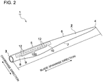
- FIG. 2 is a perspective view of a wind turbine blade to which a vortex generator according to an embodiment is to be applied.
- a wind turbine power generating apparatus 90 includes a rotor 93 including at least one (e.g. three) wind turbine blades 1 and a hub 94.
- the wind turbine blades 1 are mounted to the hub 94 in a radial fashion, the rotor 93 rotates in response to wind received by the wind turbine blades 1, and a generator (not depicted) coupled to the rotor 93 generates electric power.
- the rotor 93 is supported by a nacelle 95 disposed on an upper part of a tower 96.
- the tower 96 is disposed to stand upright on a base structure 97 (e.g. foundation structure or floating structure) disposed on water or on land.
- the wind turbine blade 1 includes a blade body 2.
- the blade body 2 includes a blade root 3 to be mounted to the hub 94 of the wind turbine power generating apparatus 90, a blade tip 4 positioned farthest from the hub 94, and an airfoil part 5 extending between the blade root 3 and the blade tip 4.
- the wind turbine blade 1 has a leading edge 6 and a trailing edge 7 from the blade root 3 to the blade tip 4. Further, an exterior shape of the blade body 2 of the wind turbine blade 1 is formed by a pressure surface 8 and a suction surface 9 disposed opposite to the pressure surface 8.
- blade spanwise direction refers to a direction connecting the blade root 3 and the blade tip 4
- blade chordwise direction refers to a direction along a line (chord) connecting the leading edge 6 and the trailing edge 7 of the blade body 2.
- the vortex generator 10 includes a plurality of main fins 12 mounted to the surface of the wind turbine blade 1 (specifically, blade body 2).
- the plurality of main fins 12 form a main fin row 100.
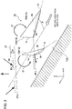
- FIG. 3 is a perspective view for describing a flow around a pair of adjacent main fins 12A, 12B according to an embodiment.
- FIG. 4 is a velocity distribution diagram showing a result of fluid analysis around a pair of adjacent main fins 12A, 12B according to an embodiment.
- FIG. 4 shows a velocity distribution 28 in a cross section at a position P 1 of trailing edges 14 of the main fins 12A, 12B, which is a cross section orthogonal to the in-flow direction of wind, and a velocity distribution 29 in a cross section at a position P 2 on a downstream side of the main fins 12A, 12B, which is also a cross section orthogonal to the in-flow direction of wind.
- regions with a higher fluid velocity are shown in darker shading
- regions with a lower fluid velocity are shown in lighter shading.
- the plurality of main fins 12 include at least one pair of fins 12A, 12B disposed adjacent to each other (see FIGs. 3 and 4 , for example).
- the pair of main fins 12 (12A, 12B) each has an airfoil shape.
- Each main fin 12 includes a leading edge 13 disposed on an upstream side with respect to the inflow direction of wind, a trailing edge 14 disposed on a downstream side with respect to the inflow direction of wind, a pressure surface 15 of the fin 12 facing toward upstream with respect to the inflow direction of wind, and a suction surface 16 of the fin 12 facing toward downstream with respect to the inflow direction of wind.
- the direction of a line connecting the leading edge 13 and the trailing edge 14 is the chordwise direction of the fin 12.
- in-flow direction of wind refers to a direction of a flow along a surface of the wind turbine blade 1 (see FIG. 2 ) at a mounting position of the vortex generator 10.
- a blade chordwise direction (see FIG. 2 ) of the wind turbine blade 1 at a mounting position of the vortex generator 10 may be used approximately.
- each of the main fins 12A, 12B may be disposed so that a gap between the pair of main fins 12A, 12B widens from upstream toward downstream with respect to the inflow direction of wind (i.e., from the side of the leading edge 6 toward the side of the trailing edge 7 of the wind turbine blade 1 (see FIG. 2 ) in a state of being mounted to the wind turbine blade 1).
- the main fin row 100 normally generates longitudinal vortices 21 on the side of the suction surfaces 16 of the main fins 12 (12A, 12B) with a lift L produced by the main fins 12.
- the longitudinal vortices 21, 22 promote momentum exchange between outside and inside of a boundary layer 31 at a downstream side of the main fins 12.
- the boundary layer 31 at a position farther from the main fins 12 is affected less by the main fins 12 and thus has a thickness D 1 which is relatively large.
- the vortices 21 generated by the main fins 12 (12A, 12B) promote momentum exchange in the height direction of the fins 12, and thus the boundary layer 32 has a thickness D 2 that is smaller than the thickness D 1 of the boundary layer 31. Accordingly, the main fin row 100 reduces the thickness of the boundary layer 31 on the surface of the wind turbine blade 1, and thereby trailing-edge separation on the wind turbine blade 1 is suppressed.
- longitudinal vortices 21 refer to vortices formed in the height direction of the fins 12.
- the main fin row 100 can achieve an effect to suppress trailing-edge separation of the wind turbine blade 1 as a whole, the present inventors conducted intensive researches and found that the main fin row 100 fails to achieve a sufficient effect to suppress separation locally at an end portion, and even worse, may promote separation at an end portion. This is due to longitudinal vortices 21 formed by the main fins 12A, 12B positioned on the end portion of the main fin row 100 having a component in a direction away from the surface of the wind turbine blade 1 between the main fins 12A, 12B, which promotes separation at the downstream side of the main fins 12.
- the vortex generator 10 further includes sub fins 120 (120A, 120B) for enhancing the effect to suppress separation at an end portion of the main fin row 100, as described below with reference to FIGs. 5A, 5B , 6A, and 6B .
- FIGs. 5A and 5B are diagrams showing a configuration example of a vortex generator 10A according to an embodiment.
- FIG. 5A is a planar view of the vortex generator 10
- FIG. 5B is a side view of the vortex generator 10A as seen from the upstream side with respect to the inflow direction of wind.
- FIGs. 6A and 6B are diagrams showing a configuration example of a vortex generator 10B according to an embodiment.
- FIG. 6A is a planar view of the vortex generator 10
- FIG. 6B is a side view of the vortex generator 10B as seen from the upstream side with respect to the inflow direction of wind.
- the sub fins 120 include at least one first sub fin 120A disposed on the surface of the wind turbine blade 1 along a first virtual line L ref1 extending from a first end portion 102 of the main fin row 100.
- the first end portion 102 is disposed on a side of the main fin row 100 that is closer to one of the blade tip 4 or the blade root 3 of the wind turbine blade 1.
- a single first sub fin 120A may be provided as shown in FIGs. 5A and 5B , or a plurality of first sub fins 120A may be provided as shown in FIGs. 6A and 6B .
- the at least one first sub fins 120A are disposed so that the first sub fin 200 which is disposed next to the first end portion 102 of the main fin row 100, of the first sub fins 120A, is at a distance d 1 from the main fin row 100.
- the distance d 1 between the main fin row 100 and the first sub fin 200 closest to the main fin row 100 satisfies an expression d 1 ⁇ d max , provided that d max is the maximum distance between a pair of adjacent main fins 12A, 12B in the main fin row 100.
- the sub fins 120 include at least one second sub fin 120B disposed on the surface of the wind turbine blade 1 along a second virtual line L ref2 extending from a second end portion 104 of the main fin row 100.
- the second end portion 104 is disposed on a side of the main fin row 100 that is closer to the other one of the blade tip 4 or the blade root 3 of the wind turbine blade 1.
- a single second sub fin 120B may be provided as shown in FIGs. 5A and 5B , or a plurality of second sub fins 120B may be provided as shown in FIGs. 6A and 6B .
- the at least one second sub fin 120B is disposed so that the second sub fin 300 which is disposed next to the second end portion 104 of the main fin row 100, of the second sub fins 120B, is at a distance d 2 from the main fin row 100.
- the distance d 2 between the main fin row 100 and the second sub fin 300 closest to the main fin row 100 satisfies an expression d 2 ⁇ d max , where d max is the maximum distance between a pair of adjacent main fins 12A, 12B in the main fin row 100.
- each sub fin 120 (120A, 120B) has a smaller fin chord length and a smaller fin height than each main fin 12 (12A, 12B). That is, provided that C main and H main are the fin chord length and the fin height of the main fin 12, respectively, the fin chord length C sub and the fin height H sub of each sub fin 120 satisfy relationships C sub ⁇ C main and H sub ⁇ H main .
- the plurality of first sub fins 120A are arranged next to the first end portion 102 of the main fin row 100 in such an order that the fin chord length and the fin height decrease with distance from the main fin row 100.
- three first sub fins 120A are disposed so as to satisfy C sub1 >C sub2 >C sub3 , and, H sub1 >H sub2 >H sub3 .
- the plurality of second sub fins 120B are arranged next to the second end portion 104 of the main fin row 100 in such an order that the fin chord length and the fin height of the second sub fins 120B decrease with distance from the main fin row 100 (C' sub1 >C' sub2 >C' sub3 , and, F' sub1 >H' sub2 >H' sub3 ).
- the sub fins 120A, 120B which are smaller than the main fins 12 are disposed adjacent to the main fin row 100 (d 1 ⁇ d max , d 2 ⁇ d max ), and thus it is possible to enhance the effect to suppress separation at an end portion of the fin row of the vortex generator 10A, 10B.
- the sub fins 120A, 120B provided, it is possible to cancel, at least partially, the effect to promote separation caused by the longitudinal vortices 21 formed in a direction away from the surface of the wind turbine blade 1 by some of the main fins 12 disposed on an end portion of the main fin row 100, as vortices 121 (see FIGs.
- the sub fins 120A, 120B themselves may form vortices in a direction away from the surface of the wind turbine blade 1, the fin chord lengths C sub , C' sub and the fin heights H sub , H' sub of the sub fins 120A, 120B are smaller than those of the main fins 12, and thus the influence of the vortices 121 formed by the sub fins 120A, 120B is smaller than that of the vortices 21 formed by the main fins 12.
- a plurality of vortex generators 10 may be disposed in the blade spanwise direction on the suction surface 9 of the blade body 2, for instance, linearly along the reference line L ref1 , (see FIGs. 2 and 7 ). In some embodiments, a plurality of vortex generators 10 may be disposed diagonally with respect to the blade spanwise direction, for instance, linearly along the reference line L ref2 (see FIG 7 ).
- a plurality of main fins 12a forms one or more main fin rows 100. In some embodiments, each of the fins 12 (12A, 12B) is disposed inclined to form a predetermined angle with an inflow direction of wind (see FIGs. 3 and 4 ).
- the vortex generator 10 includes a base plate (base plate) 11 to be fixed to a surface of the wind turbine blade 1 (more specifically, to a surface of the blade body 2) and at least one fin 12 disposed upright on the base plate 11.
- the base plate 11 may have a circular shape, an oval shape, or a polygonal shape such as a trapezoidal shape and a rectangular shape.
- each sub fin 120 may be disposed upright on the base plate 11A, as depicted in FIGs. 8 and 9 , for instance.
- the base plate 11A may have an oval shape or a quadrilateral shape such as a trapezoidal shape.
- the sub fins 12B can be mounted to the wind turbine blade 1 by simply mounting the base plate 11A to the wind turbine blade 1, and thus it is possible to improve the workability for mounting the plurality of sub fins 120 to the wind turbine blade 1.
- the sub fins 120 formed to decrease in size with distance from the main fin row 100 are formed integrally with the base plate 11, and thus it is possible to prevent the small fins 120 from being lost and to reduce the efforts for proper handling.
- one or more sub fins 120 and one or more main fins 12 may be disposed on the same base plate 11 (see FIG 10 , for instance). Accordingly, it is possible to further reduce the man hours for installing the vortex generator 10 on the wind turbine blade 1.
- the at least one sub fin 120 may be disposed on an end portion (first end portion) 102 of the main fin row 100 at the side closer to the blade tip 4 of the wind turbine blade 1 (see FIG. 2 ). Accordingly, it is possible to suppress the effect to promote separation with the sub fins 120 at the end portion of the fin row of the vortex generator 10, for a portion of the wind turbine blade 1 that has a great influence on the aerodynamic performance (a portion closer to the tip than the blade root portion (blade root 3)). Thus, it is possible to improve the aerodynamic performance of the wind turbine blade 1.
- one or more sub fins 120 (second sub fins) may be disposed on an end portion (second end portion) 104 of the main fin row 100 at the side closer to the blade root 3 of the wind turbine blade 1 (see FIG 2 ).
- the at least one sub fin 120A may be disposed so that the center of each sub fin 120A with respect to the fin chord length direction is on the extension line of the center of each of the plurality of main fins 12 with respect to the fin chord length direction. Accordingly, the aerodynamic effect achieved by the at least one sub fin 120 arranged on the extension line of the main fin row can be exerted efficiently on an end portion of the main fin row, and thus it is possible to improve the aerodynamic property of the wind turbine blade 1 efficiently.
- FIG. 12 is a flowchart of a method of installing a vortex generator 10 according to an embodiment.
- vortex generator 10 is mounted to the suction surface 9 of the wind turbine blade 1 (blade body 2) in an example described below, the vortex generator 10 can be mounted to the pressure surface 8 of the wind turbine blade 1 by a similar method.
- a method of installing a vortex generator 10 includes: a step (S1) of mounting a plurality of main fins 12 to a surface of the wind turbine blade 1, a step (S2) of mounting at least one sub fin 120 to the surface of the wind turbine blade 1, along a virtual line (the first virtual line) extending from an end portion (the first end portion) of the main fin row 100 at the side of the blade tip 4 or the blade root 3 of the wind turbine blade 1, the at least one first sub fin 120 having a fin chord length and a fin height which are smaller than those of each of the main fins 12; and a step (S3) of determining a mounting position of the sub fin 12b so as to satisfy an expression d ⁇ d max , provided that d is a distance between the main fin row 100 and the sub fin 120, disposed next to the first end portion of the main fin row 100, of the at least one sub fin 120, and d max is a maximum distance between an adjacent pair of the main fins 12
- a plurality of vortex generators 10 having main fins 12 are mounted to the surface of the wind turbine blade 1 (step S1).
- the mounting position of each vortex generator 10 may be determined on the basis of fluid-analysis results on the wind turbine blade 1.
- an ideal mounting position of each vortex generator 10 on the wind turbine blade 1 may be calculated from fluid analysis on the wind turbine blade 1, and the ideal mounting position may be determined as the position for actually mounting each vortex generator 10.
- ideal mounting positions of the plurality of vortex generators 10 shown in fluid-analysis results on the wind turbine blade 1 may be approximated by one or more lines, and the mounting positions of the plurality of vortex generators 10 may be determined on the line.
- the vortex generator 10 may be mounted to the surface (suction surface 9 in this case) of the wind turbine blade 1, so that a reference mark (not depicted) indicating orientation of the vortex generator 10 is disposed along the line L ref1 connecting reference points P 1 and P 2 .
- the vortex generator 10 may be mounted to the surface (suction surface 9 in this case) of the wind turbine blade 1, so that a reference mark indicating orientation of the vortex generator 10 is disposed along the line L ref2 connecting reference points P 2 and P 3 .
- the plurality of vortex generators 10 may be aligned linearly along the line L ref , and the mounting direction of each vortex generator 10 may be adjusted with reference to the line L ref , thereby mounting the plurality of vortex generators 10 to the wind turbine blade 1.
- the plurality of vortex generators 10 mounted to the wind turbine blade 1 with reference to the single line L ref it is possible to mount the vortex generator 10 to the wind turbine blade 1 efficiently.
- the vortex generators 10 are aligned linearly and mounted to the wind turbine blade 1, along each of the line L ref1 connecting the reference points P 1 and P 2 and the line L ref2 connecting the reference points P 2 and P 3 , on the surface of the wind turbine blade 1.
- the mounting position and the mounting angle of the vortex generator 10 on the wind turbine blade 1 are adjusted as described above, and then the vortex generator 10 is fixed to the wind turbine blade 1.
- the vortex generator 10 may be fixed to the wind turbine blade 1 with an adhesive agent or a double-sided adhesive tape.
- At least one sub fin 12b having a smaller fin chord length and a smaller fin height than each main fin 12 is mounted to the surface of the wind turbine blade 1, along a virtual line (the first virtual line or the second virtual line) extending from an end portion (the first end portion or the second end portion) of the main fin row on the side of the blade tip 4 or the blade root 3 of the wind turbine blade 1 (step S2).
- the mounting position of the sub fin 120 is determined so that the distance d between the main fin row 100 and the sub fin 120 next to the first end portion of the main fin row 100, of the at least one sub fin 120, satisfies an expression d ⁇ d max , provided that d max is the maximum distance between a pair of adjacent main fins 12A, 12B in the main fin row 100 (step S3).
- an expression of relative or absolute arrangement such as “in a direction”, “along a direction”, “parallel”, “orthogonal”, “centered”, “concentric” and “coaxial” shall not be construed as indicating only the arrangement in a strict literal sense, but also includes a state where the arrangement is relatively displaced by a tolerance, or by an angle or a distance whereby it is possible to achieve the same function.
- an expression of an equal state such as “same” “equal” and “uniform” shall not be construed as indicating only the state in which the feature is strictly equal, but also includes a state in which there is a tolerance or a difference that can still achieve the same function.
- an expression of a shape such as a rectangular shape or a cylindrical shape shall not be construed as only the geometrically strict shape, but also includes a shape with unevenness or chamfered corners within the range in which the same effect can be achieved.
Abstract
Description
- The present invention relates to a vortex generator, an installation method for the same, a wind turbine blade, and a wind turbine power generating apparatus.
- Approaches to improve aerodynamic performance of a wind turbine blade have been sought for some time to improve operation efficiency of a wind turbine. In one of the approaches, a vortex generator (VG) is disposed on a surface of a wind turbine blade to suppress separation of a flow along the surface of the wind turbine blade.
-
Patent Documents 1 to 10 disclose a vortex generator having a base plate to be mounted to a surface of a wind turbine blade, and a plurality of fins (VG fins) disposed upright on the base plate. -
- Patent Document 1:
EP2799710A - Patent Document 2:
US Patent Application Publication No. 2014/0140856 - Patent Document 3:
EP2548800A - Patent Document 4:
EP2799709A - Patent Document 5:
WO2007/140771A - Patent Document 6:
EP2031241A - Patent Document 7:
EP2484898A - Patent Document 8:
WO2015/030573A - Patent Document 9:
EP2597300A - Patent Document 10:
DE102013201871A - A typical vortex generator includes a fin row formed by a plurality of VG fins, as described in
Patent Documents 1 to 10. As a result of intensive researches by the present inventors, it was found that an effect to suppress separation cannot be sufficiently achieved at an end portion of a fin row of a vortex generator, and even worse, some VG fins disposed on an end portion of a fin row may form vortices in a direction away from the surface of the wind turbine blade, which may actually promote separation. - An object of at least some embodiments of the present invention is to provide a vortex generator, an installation method for the same, a wind turbine blade, and a wind turbine power generating apparatus, whereby it is possible to improve an effect to suppress separation, at an end portion of a fin row of a vortex generator.
- (1) A vortex generator for a wind turbine blade, according to at least one embodiment of the present invention, comprises: a plurality of main fins disposed on a surface of the wind turbine blade; and at least one first sub fin having a fin chord length and a fin height which are smaller than those of each of the main fins, the at least one first sub fin being disposed on the surface of the wind turbine blade along a first virtual line extending from a first end portion of a main fin row at a side of a blade tip or a blade root of the wind turbine blade. An expression d ≤ dmax is satisfied, provided that d is a distance between the main fin row and the first sub fin disposed next to the first end portion of the main fin row of the at least one first sub fin, and dmax is a maximum distance between an adjacent pair of the main fins in the main fin row.
At an end portion of a fin row of a vortex generator, it is difficult to achieve a sufficient effect to suppress separation, due to the influence of vortices generated by the fins in a direction away from the surface of the wind turbine blade.
In this regard, with the above configuration (1), the first sub fin being smaller than the main fins is disposed adjacent to the main fin row (d ≤ dmax), and thus it is possible to enhance the effect to suppress separation at the end portion of the fin row of the vortex generator. Specifically, with the first sub fin, it is possible to cancel, at least partially, the effect to promote separation caused by the vortices in a direction away from the surface of the wind turbine blade formed by some main fins disposed on an end portion of the main fin row, as vortices formed by the first sub fin attract a relatively-fast flow outside the boundary layer toward the surface of the wind turbine blade. Furthermore, while the first sub fin itself may form vortices in a direction away from the surface of the wind turbine blade, the fin chord length and the fin height of the first sub fin are smaller than those of the main fins, and thus the influence of the vortices formed by the first sub fins are smaller than that of the vortices formed by the main fins. Thus, with the above configuration (1), it is possible to enhance the effect to suppress separation at an end portion of the fin row as the vortex generator as a whole. - (2) In some embodiments, in the above configuration (1), a fin chord length direction of the first sub fin which is farthest from the main fin row, of the at least one first sub fin, is inclined from the first virtual line so as to extend away from the main fin row toward a leading edge of the wind turbine blade.
With the above configuration (2), among the first sub fins disposed on the first virtual line extending from the main fin row, the first sub fin farthest from the main fin row is disposed so as to be away from the main fin row toward the leading edge side. Specifically, the fins (first sub fins) disposed on an end potion of the row of the vortex generator including the main fins and the first sub fins is disposed away from the main fin row as the fins get closer to the leading edge. Accordingly, at the end portion of the vortex generator, it is possible to suppress separation by attracting a relatively-fast flow outside the boundary layer toward the blade surface with vertices formed by provision of the first sub fin. - (3) In some embodiments, in the above configuration (1) or (2), the at least one first sub fin includes a plurality of first sub fins having the fin chord length and the fin height which decrease with distance from the main fin row.
With the above configuration (3), a plurality of first sub fins are provided, and formed to have a fin chord length and a fin height which decrease gradually with distance from the main fin. In other words, the fins do not terminate suddenly at the end portion of the main fin row, but the aerodynamic effect of the fins decreases gradually, and thus it is possible to achieve the effect to suppress separation suitably at the end portion of the fin row as the vortex generator as a whole. - (4) In some embodiments, in any one of the above configurations (1) to (3), the vortex generator further comprises a first base plate fixed to the surface of the wind turbine blade. The at least one first sub fin includes a plurality of first sub fins disposed upright on the first base plate.
With the above configuration (4), the plurality of first sub fins are disposed upright on the first base plate, and thus the first sub fins can be mounted to the wind turbine blade by merely mounting the first base plate to the wind turbine blade. Thus, it is possible to improve the workability for mounting the plurality of first sub fins to the wind turbine blade. Further, the first sub fins formed to have a size that decreases with distance from the main fin row are formed integrally with the first base plate, and thus it is possible to prevent the small fins from being lost, and to reduce the efforts for proper handling. - (5) In some embodiments, in any one of the above configurations (1) to (4), the vortex generator further comprises a first base plate fixed to the surface of the wind turbine blade. At least one of the main fins which forms the first end portion of the main fin row and at least one of the first sub fin are disposed upright on the first base plate.
With the above configuration (5), at least one first sub fin and at least one main fin are disposed upright on the first base plate. Specifically, at least one first sub fin and at least one main fin are formed integrally via the first base plate, and thus it is possible to reduce the man hours for mounting the vortex generator to the wind turbine blade, and to simplify the mounting work. - (6) In some embodiments, in any one of the above configurations (1) to (5), the first end portion is an end portion, disposed at the side of the blade tip of the wind turbine blade, of the main fin row.
With the above configuration (6), from the principle described in the above (1), it is possible to suppress the effect to promote separation with the first sub fin at the end portion of the fin row of the vortex generator, for a portion of the wind turbine blade that has a great influence on the aerodynamic performance (a portion closer to the tip than the blade root portion). Thus, it is possible to improve the aerodynamic performance of the wind turbine blade. - (7) In some embodiments, in any one of the above configurations (1) to (6), the at least one first sub fin is disposed so that a center of each of the first sub fin with respect to a fin chord length direction is on a line connecting respective centers of the plurality of main fins in the fin chord length direction.
With the above configuration (7), the aerodynamic effect achieved by the at least one first sub fin arranged on the extension line of the main fin row can be exerted efficiently on the end portion of the main fin row, and thus it is possible to improve the aerodynamic property of the wind turbine blade efficiently. - (8) In some embodiments, in any one of the above configurations (1) to (7), S1/S2 is at least 0.8 and at most 1.2, provided that S1 is a distance between an adjacent pair of the main fins at a leading-edge side, and S2 is a distance between an adjacent pair of the main fins at a trailing-edge side.
With the above configuration (8), basic units of the main fins are disposed at a substantially constant distance without being too apart or too close, and thus it is possible to achieve the effect to suppress separation substantially uniformly over the entire installation range of the vortex generator. - (9) A wind turbine blade according to at least some embodiments of the present invention comprises: a blade body; and the vortex generator according to any one of
claims 1 to 8 mounted to a surface of the blade body.
With the above configuration (9), as described in the above (1), the first sub fin being smaller than the main fins is disposed adjacent to the main fin row, and thus it is possible to enhance the effect to suppress separation at the end portion of the fin row of the vortex generator. Thus, it is possible to provide a wind turbine blade with an improved aerodynamic performance. - (10) A wind turbine power generating apparatus according to at least some embodiments of the present invention comprises the wind turbine blade according to the above (9).
With the above configuration (10), the wind turbine blade having the configuration of the above (9) is provided, and thus it is possible to provide a wind turbine power generating apparatus with an improved aerodynamic performance. - (11) A method of installing a vortex generator on a wind turbine blade according to at least some embodiments of the present invention comprises: a step of mounting a plurality of main fins on a surface of the wind turbine blade; a step of mounting at least one first sub fin to the surface of the wind turbine blade, along a first virtual line extending from a first end portion of a main fin row at a side of a blade tip or a blade root of the wind turbine blade, the at least one first sub fin having a fin chord length and a fin height which are smaller than those of each of the main fins; and a step of determining a mounting position of the first sub fin so that d satisfies an expression d ≤ dmax, provided that d is a distance between the main fin row and the first sub fin disposed next to the first end portion of the main fin row of the at least one first sub fin, and dmax is a maximum distance between an adjacent pair of the main fins in the main fin row.
- According to the above method (11), as described in the above (1), the first sub fins which are smaller than the main fins are disposed adjacent to the main fin row, and thus it is possible to enhance the effect to suppress separation at an end portion of the fin row of the vortex generator.
- According to at least one embodiment of the present invention, it is possible to enhance the effect to suppress separation at an end portion of the fin row for the vortex generator.
-
-
FIG 1 is a schematic configuration diagram of a wind turbine power generating apparatus including a wind turbine blade to which a vortex generator according to an embodiment is to be applied. -
FIG. 2 is a perspective view of a wind turbine blade to which a vortex generator according to an embodiment is to be applied. -
FIG. 3 is a perspective view for describing a flow around a main fin row according to an embodiment. -
FIG. 4 is a velocity distribution diagram showing a result of fluid analysis around a main fin row according to an embodiment. -
FIG. 5A is a planar view of an end portion of a vortex generator according to an embodiment.FIG. 5B is a side view of an end portion of a vortex generator according to an embodiment. -
FIG. 6A is a planar view of an end portion of a vortex generator according to an embodiment.FIG. 6B is a side view of an end portion of a vortex generator according to an embodiment. -
FIG. 7 is a configuration diagram of a vortex generator according to an embodiment. -
FIG. 8 is a planar view of a sub fin provided for an end portion of a vortex generator according to an embodiment. -
FIG. 9 is a diagram of a sub fin provided for an end portion of a vortex generator according to an embodiment. -
FIG. 10 is a diagram of a sub fin provided for an end portion of a vortex generator according to an embodiment. -
FIG. 11 is a flowchart of a method of installing avortex generator 10 according to an embodiment. - Embodiments of the present invention will now be described in detail with reference to the accompanying drawings. It is intended, however, that unless particularly specified, dimensions, materials, shapes, relative positions and the like of components described in the embodiments shall be interpreted as illustrative only and not intended to limit the scope of the present invention.
- With reference to
FIGs. 1 and2 , a wind turbine blade will now be described, to which a vortex generator according to some embodiments is to be applied.FIG. 1 is a schematic configuration diagram of a wind turbine power generating apparatus including a wind turbine blade to which a vortex generator according to an embodiment is to be applied.FIG. 2 is a perspective view of a wind turbine blade to which a vortex generator according to an embodiment is to be applied. - As depicted in
FIG. 1 , a wind turbinepower generating apparatus 90 includes arotor 93 including at least one (e.g. three)wind turbine blades 1 and ahub 94. Thewind turbine blades 1 are mounted to thehub 94 in a radial fashion, therotor 93 rotates in response to wind received by thewind turbine blades 1, and a generator (not depicted) coupled to therotor 93 generates electric power. - In the embodiment depicted in
FIG. 1 , therotor 93 is supported by anacelle 95 disposed on an upper part of atower 96. Thetower 96 is disposed to stand upright on a base structure 97 (e.g. foundation structure or floating structure) disposed on water or on land. - As depicted in
FIG. 2 , thewind turbine blade 1 includes ablade body 2. - The
blade body 2 includes ablade root 3 to be mounted to thehub 94 of the wind turbinepower generating apparatus 90, ablade tip 4 positioned farthest from thehub 94, and anairfoil part 5 extending between theblade root 3 and theblade tip 4. Thewind turbine blade 1 has aleading edge 6 and a trailingedge 7 from theblade root 3 to theblade tip 4. Further, an exterior shape of theblade body 2 of thewind turbine blade 1 is formed by apressure surface 8 and asuction surface 9 disposed opposite to thepressure surface 8. - For the
wind turbine blade 1 depicted inFIG. 2 ,vortex generators 10 are mounted to thesuction surface 9 of theblade body 2. In the present specification, "blade spanwise direction" refers to a direction connecting theblade root 3 and theblade tip 4, and "blade chordwise direction" refers to a direction along a line (chord) connecting theleading edge 6 and the trailingedge 7 of theblade body 2. - In some embodiments, the
vortex generator 10 includes a plurality ofmain fins 12 mounted to the surface of the wind turbine blade 1 (specifically, blade body 2). The plurality ofmain fins 12 form amain fin row 100. - Next, with reference to
FIGs. 3 and4 , the specific configuration of the main fins 12 (12A, 12B) and the aerodynamic effect of themain fin row 100 will be described. -
FIG. 3 is a perspective view for describing a flow around a pair of adjacentmain fins FIG. 4 is a velocity distribution diagram showing a result of fluid analysis around a pair of adjacentmain fins -
FIG. 4 shows avelocity distribution 28 in a cross section at a position P1 of trailingedges 14 of themain fins velocity distribution 29 in a cross section at a position P2 on a downstream side of themain fins velocity distributions - In some embodiments, the plurality of
main fins 12 include at least one pair offins FIGs. 3 and4 , for example). In some embodiments, the pair of main fins 12 (12A, 12B) each has an airfoil shape. Eachmain fin 12 includes aleading edge 13 disposed on an upstream side with respect to the inflow direction of wind, a trailingedge 14 disposed on a downstream side with respect to the inflow direction of wind, apressure surface 15 of thefin 12 facing toward upstream with respect to the inflow direction of wind, and asuction surface 16 of thefin 12 facing toward downstream with respect to the inflow direction of wind. In thisfin 12, the direction of a line connecting the leadingedge 13 and the trailingedge 14 is the chordwise direction of thefin 12. - In the present specification, "in-flow direction of wind" refers to a direction of a flow along a surface of the wind turbine blade 1 (see
FIG. 2 ) at a mounting position of thevortex generator 10. As an "in-flow direction of wind", a blade chordwise direction (seeFIG. 2 ) of thewind turbine blade 1 at a mounting position of thevortex generator 10 may be used approximately. - In some embodiments, for instance, each of the
main fins main fins leading edge 6 toward the side of the trailingedge 7 of the wind turbine blade 1 (seeFIG. 2 ) in a state of being mounted to the wind turbine blade 1). - As depicted in
FIGs. 3 and4 , themain fin row 100 normally generateslongitudinal vortices 21 on the side of the suction surfaces 16 of the main fins 12 (12A, 12B) with a lift L produced by themain fins 12. Thelongitudinal vortices 21, 22 promote momentum exchange between outside and inside of aboundary layer 31 at a downstream side of themain fins 12. Specifically, theboundary layer 31 at a position farther from themain fins 12 is affected less by themain fins 12 and thus has a thickness D1 which is relatively large. In contrast, at a position closer to themain fins 12, thevortices 21 generated by the main fins 12 (12A, 12B) promote momentum exchange in the height direction of thefins 12, and thus theboundary layer 32 has a thickness D2 that is smaller than the thickness D1 of theboundary layer 31. Accordingly, themain fin row 100 reduces the thickness of theboundary layer 31 on the surface of thewind turbine blade 1, and thereby trailing-edge separation on thewind turbine blade 1 is suppressed. - It should be noted that the
longitudinal vortices 21 refer to vortices formed in the height direction of thefins 12. - Although the
main fin row 100 can achieve an effect to suppress trailing-edge separation of thewind turbine blade 1 as a whole, the present inventors conducted intensive researches and found that themain fin row 100 fails to achieve a sufficient effect to suppress separation locally at an end portion, and even worse, may promote separation at an end portion. This is due tolongitudinal vortices 21 formed by themain fins main fin row 100 having a component in a direction away from the surface of thewind turbine blade 1 between themain fins main fins 12. - In view of this, in some embodiments, the
vortex generator 10 further includes sub fins 120 (120A, 120B) for enhancing the effect to suppress separation at an end portion of themain fin row 100, as described below with reference toFIGs. 5A, 5B ,6A, and 6B . -
FIGs. 5A and 5B are diagrams showing a configuration example of avortex generator 10A according to an embodiment.FIG. 5A is a planar view of thevortex generator 10, andFIG. 5B is a side view of thevortex generator 10A as seen from the upstream side with respect to the inflow direction of wind. -
FIGs. 6A and 6B are diagrams showing a configuration example of avortex generator 10B according to an embodiment.FIG. 6A is a planar view of thevortex generator 10, andFIG. 6B is a side view of thevortex generator 10B as seen from the upstream side with respect to the inflow direction of wind. - In some embodiments, as depicted in
FIGs. 5A to 6B , the sub fins 120 include at least onefirst sub fin 120A disposed on the surface of thewind turbine blade 1 along a first virtual line Lref1 extending from afirst end portion 102 of themain fin row 100. Thefirst end portion 102 is disposed on a side of themain fin row 100 that is closer to one of theblade tip 4 or theblade root 3 of thewind turbine blade 1. A singlefirst sub fin 120A may be provided as shown inFIGs. 5A and 5B , or a plurality offirst sub fins 120A may be provided as shown inFIGs. 6A and 6B . - Further, the at least one
first sub fins 120A are disposed so that thefirst sub fin 200 which is disposed next to thefirst end portion 102 of themain fin row 100, of thefirst sub fins 120A, is at a distance d1 from themain fin row 100. The distance d1 between themain fin row 100 and thefirst sub fin 200 closest to themain fin row 100 satisfies an expression d1 ≤dmax, provided that dmax is the maximum distance between a pair of adjacentmain fins main fin row 100. - Further, as depicted in
FIGs. 5A to 6B , the sub fins 120 include at least onesecond sub fin 120B disposed on the surface of thewind turbine blade 1 along a second virtual line Lref2 extending from asecond end portion 104 of themain fin row 100. Thesecond end portion 104 is disposed on a side of themain fin row 100 that is closer to the other one of theblade tip 4 or theblade root 3 of thewind turbine blade 1. Similarly to thefirst sub fin 120A, a singlesecond sub fin 120B may be provided as shown inFIGs. 5A and 5B , or a plurality ofsecond sub fins 120B may be provided as shown inFIGs. 6A and 6B . - Further, the at least one
second sub fin 120B is disposed so that the second sub fin 300 which is disposed next to thesecond end portion 104 of themain fin row 100, of thesecond sub fins 120B, is at a distance d2 from themain fin row 100. The distance d2 between themain fin row 100 and the second sub fin 300 closest to themain fin row 100 satisfies an expression d2≤dmax, where dmax is the maximum distance between a pair of adjacentmain fins main fin row 100. - As depicted in
FIGs. 5 and6 , each sub fin 120 (120A, 120B) has a smaller fin chord length and a smaller fin height than each main fin 12 (12A, 12B). That is, provided that Cmain and Hmain are the fin chord length and the fin height of themain fin 12, respectively, the fin chord length Csub and the fin height Hsub of each sub fin 120 satisfy relationships Csub<Cmain and Hsub<Hmain. - In the embodiment depicted in
FIGs. 6A and 6B , the plurality offirst sub fins 120A are arranged next to thefirst end portion 102 of themain fin row 100 in such an order that the fin chord length and the fin height decrease with distance from themain fin row 100. Specifically, in an example depicted inFIGs. 6A and 6B , threefirst sub fins 120A are disposed so as to satisfy Csub1>Csub2>Csub3, and, Hsub1>Hsub2>Hsub3. - Similarly, the plurality of
second sub fins 120B are arranged next to thesecond end portion 104 of themain fin row 100 in such an order that the fin chord length and the fin height of thesecond sub fins 120B decrease with distance from the main fin row 100 (C'sub1>C'sub2>C'sub3, and, F'sub1>H'sub2>H'sub3). - In the
vortex generator sub fins main fins 12 are disposed adjacent to the main fin row 100 (d1≤dmax, d2≤dmax), and thus it is possible to enhance the effect to suppress separation at an end portion of the fin row of thevortex generator sub fins longitudinal vortices 21 formed in a direction away from the surface of thewind turbine blade 1 by some of themain fins 12 disposed on an end portion of themain fin row 100, as vortices 121 (seeFIGs. 5B and6B ) formed by thesub fins wind turbine blade 1. Furthermore, while thesub fins wind turbine blade 1, the fin chord lengths Csub, C'sub and the fin heights Hsub, H'sub of thesub fins main fins 12, and thus the influence of thevortices 121 formed by thesub fins vortices 21 formed by themain fins 12. Thus, it is possible to enhance the effect to suppress separation at an end portion of the fin row as thevortex generator - In some embodiments, a plurality of
vortex generators 10 may be disposed in the blade spanwise direction on thesuction surface 9 of theblade body 2, for instance, linearly along the reference line Lref1, (seeFIGs. 2 and7 ). In some embodiments, a plurality ofvortex generators 10 may be disposed diagonally with respect to the blade spanwise direction, for instance, linearly along the reference line Lref2 (seeFIG 7 ). A plurality of main fins 12a forms one or moremain fin rows 100. In some embodiments, each of the fins 12 (12A, 12B) is disposed inclined to form a predetermined angle with an inflow direction of wind (seeFIGs. 3 and4 ). - In some embodiments, the
vortex generator 10 may be disposed so that S1/S2 is at least 0.8 and at most 1.2 (S1/S2=0.8 to 1.2), provided that S1 is the distance between the maximum distance between adjacentmain fins leading edge 6 of thewind turbine blade 1, and S2 is the distance between the maximum distance between adjacentmain fins edge 7 of the wind turbine blade 1 (seeFIGs. 8 to 10 , for instance). Accordingly, basic units of themain fins vortex generator 10. - In some embodiments, the
vortex generator 10 includes a base plate (base plate) 11 to be fixed to a surface of the wind turbine blade 1 (more specifically, to a surface of the blade body 2) and at least onefin 12 disposed upright on thebase plate 11. In some embodiments, thebase plate 11 may have a circular shape, an oval shape, or a polygonal shape such as a trapezoidal shape and a rectangular shape. - In some embodiments, each sub fin 120 may be disposed upright on the
base plate 11A, as depicted inFIGs. 8 and 9 , for instance. Thebase plate 11A may have an oval shape or a quadrilateral shape such as a trapezoidal shape. Accordingly, thesub fins 12B can be mounted to thewind turbine blade 1 by simply mounting thebase plate 11A to thewind turbine blade 1, and thus it is possible to improve the workability for mounting the plurality of sub fins 120 to thewind turbine blade 1. Further, the sub fins 120 formed to decrease in size with distance from themain fin row 100 are formed integrally with thebase plate 11, and thus it is possible to prevent the small fins 120 from being lost and to reduce the efforts for proper handling. - In some embodiments, one or more sub fins 120 and one or more
main fins 12 may be disposed on the same base plate 11 (seeFIG 10 , for instance). Accordingly, it is possible to further reduce the man hours for installing thevortex generator 10 on thewind turbine blade 1. - In some embodiments, the at least one sub fin 120 may be disposed on an end portion (first end portion) 102 of the
main fin row 100 at the side closer to theblade tip 4 of the wind turbine blade 1 (seeFIG. 2 ). Accordingly, it is possible to suppress the effect to promote separation with the sub fins 120 at the end portion of the fin row of thevortex generator 10, for a portion of thewind turbine blade 1 that has a great influence on the aerodynamic performance (a portion closer to the tip than the blade root portion (blade root 3)). Thus, it is possible to improve the aerodynamic performance of thewind turbine blade 1. In some embodiments, one or more sub fins 120 (second sub fins) may be disposed on an end portion (second end portion) 104 of themain fin row 100 at the side closer to theblade root 3 of the wind turbine blade 1 (seeFIG 2 ). - In some embodiments, the at least one
sub fin 120A may be disposed so that the center of eachsub fin 120A with respect to the fin chord length direction is on the extension line of the center of each of the plurality ofmain fins 12 with respect to the fin chord length direction. Accordingly, the aerodynamic effect achieved by the at least one sub fin 120 arranged on the extension line of the main fin row can be exerted efficiently on an end portion of the main fin row, and thus it is possible to improve the aerodynamic property of thewind turbine blade 1 efficiently. - Next, a method of installing the
vortex generator 10 to thewind turbine blade 1 according to some embodiments will be described with reference toFIG. 11 . FIG. 12 is a flowchart of a method of installing avortex generator 10 according to an embodiment. - While the
vortex generator 10 is mounted to thesuction surface 9 of the wind turbine blade 1 (blade body 2) in an example described below, thevortex generator 10 can be mounted to thepressure surface 8 of thewind turbine blade 1 by a similar method. - As depicted in FIG. 12, a method of installing a
vortex generator 10 according to some embodiments includes: a step (S1) of mounting a plurality ofmain fins 12 to a surface of thewind turbine blade 1, a step (S2) of mounting at least one sub fin 120 to the surface of thewind turbine blade 1, along a virtual line (the first virtual line) extending from an end portion (the first end portion) of themain fin row 100 at the side of theblade tip 4 or theblade root 3 of thewind turbine blade 1, the at least one first sub fin 120 having a fin chord length and a fin height which are smaller than those of each of themain fins 12; and a step (S3) of determining a mounting position of thesub fin 12b so as to satisfy an expression d ≤ dmax, provided that d is a distance between themain fin row 100 and the sub fin 120, disposed next to the first end portion of themain fin row 100, of the at least one sub fin 120, and dmax is a maximum distance between an adjacent pair of themain fins - In the method of installing the
vortex generator 10 according to some embodiments, a plurality ofvortex generators 10 havingmain fins 12 are mounted to the surface of the wind turbine blade 1 (step S1). In an embodiment, the mounting position of eachvortex generator 10 may be determined on the basis of fluid-analysis results on thewind turbine blade 1. - In an embodiment, an ideal mounting position of each
vortex generator 10 on thewind turbine blade 1 may be calculated from fluid analysis on thewind turbine blade 1, and the ideal mounting position may be determined as the position for actually mounting eachvortex generator 10. - In an embodiment, ideal mounting positions of the plurality of
vortex generators 10 shown in fluid-analysis results on thewind turbine blade 1 may be approximated by one or more lines, and the mounting positions of the plurality ofvortex generators 10 may be determined on the line. In some embodiments, thevortex generator 10 may be mounted to the surface (suction surface 9 in this case) of thewind turbine blade 1, so that a reference mark (not depicted) indicating orientation of thevortex generator 10 is disposed along the line Lref1 connecting reference points P1 and P2. Further, in some embodiments, thevortex generator 10 may be mounted to the surface (suction surface 9 in this case) of thewind turbine blade 1, so that a reference mark indicating orientation of thevortex generator 10 is disposed along the line Lref2 connecting reference points P2 and P3. - Further, as depicted in
FIG. 7 , the plurality ofvortex generators 10 may be aligned linearly along the line Lref, and the mounting direction of eachvortex generator 10 may be adjusted with reference to the line Lref, thereby mounting the plurality ofvortex generators 10 to thewind turbine blade 1. As described above, with the plurality ofvortex generators 10 mounted to thewind turbine blade 1 with reference to the single line Lref, it is possible to mount thevortex generator 10 to thewind turbine blade 1 efficiently. - In the example depicted in
FIG 7 , thevortex generators 10 are aligned linearly and mounted to thewind turbine blade 1, along each of the line Lref1 connecting the reference points P1 and P2 and the line Lref2 connecting the reference points P2 and P3, on the surface of thewind turbine blade 1. - The mounting position and the mounting angle of the
vortex generator 10 on thewind turbine blade 1 are adjusted as described above, and then thevortex generator 10 is fixed to thewind turbine blade 1. At this time, thevortex generator 10 may be fixed to thewind turbine blade 1 with an adhesive agent or a double-sided adhesive tape. - Next, in some embodiments, at least one
sub fin 12b having a smaller fin chord length and a smaller fin height than eachmain fin 12 is mounted to the surface of thewind turbine blade 1, along a virtual line (the first virtual line or the second virtual line) extending from an end portion (the first end portion or the second end portion) of the main fin row on the side of theblade tip 4 or theblade root 3 of the wind turbine blade 1 (step S2). At this time, the mounting position of the sub fin 120 is determined so that the distance d between themain fin row 100 and the sub fin 120 next to the first end portion of themain fin row 100, of the at least one sub fin 120, satisfies an expression d ≤ dmax, provided that dmax is the maximum distance between a pair of adjacentmain fins - According to some embodiments described above, it is possible to enhance the effect to suppress separation at an end portion of the fin row for the
vortex generator 10. - Embodiments of the present invention were described in detail above, but the present invention is not limited thereto, and various amendments and modifications may be implemented.
- Further, in the present specification, an expression of relative or absolute arrangement such as "in a direction", "along a direction", "parallel", "orthogonal", "centered", "concentric" and "coaxial" shall not be construed as indicating only the arrangement in a strict literal sense, but also includes a state where the arrangement is relatively displaced by a tolerance, or by an angle or a distance whereby it is possible to achieve the same function.
- For instance, an expression of an equal state such as "same" "equal" and "uniform" shall not be construed as indicating only the state in which the feature is strictly equal, but also includes a state in which there is a tolerance or a difference that can still achieve the same function.
- Further, for instance, an expression of a shape such as a rectangular shape or a cylindrical shape shall not be construed as only the geometrically strict shape, but also includes a shape with unevenness or chamfered corners within the range in which the same effect can be achieved.
- On the other hand, an expression such as "comprise", "include", "have", "contain" and "constitute" are not intended to be exclusive of other components.
Claims (11)
- A vortex generator for a wind turbine blade, comprising:a plurality of main fins disposed on a surface of the wind turbine blade; andat least one first sub fin having a fin chord length and a fin height which are smaller than those of each of the main fins, the at least one first sub fin being disposed on the surface of the wind turbine blade along a first virtual line extending from a first end portion of a main fin row at a side of a blade tip or a blade root of the wind turbine blade,wherein d satisfies an expression d ≤ dmax, provided that d is a distance between the main fin row and the first sub fin disposed next to the first end portion of the main fin row of the at least one first sub fin, and dmax is a maximum distance between an adjacent pair of the main fins in the main fin row.
- The vortex generator for a wind turbine blade according to claim 1,
wherein a fin chord length direction of the first sub fin which is farthest from the main fin row of the at least one first sub fin is inclined from the first virtual line so as to extend away from the main fin row toward a leading edge of the wind turbine blade. - The vortex generator for a wind turbine blade according to claim 1 or 2,
wherein the at least one first sub fin includes a plurality of first sub fins having the fin chord length and the fin height which decrease with distance from the main fin row. - The vortex generator for a wind turbine blade according to any one of claims 1 to 3, further comprising a first base plate fixed to the surface of the wind turbine blade,
wherein the at least one first sub fin includes a plurality of first sub fins disposed upright on the first base plate. - The vortex generator for a wind turbine blade according to any one of claims 1 to 4, further comprising a first base plate fixed to the surface of the wind turbine blade,
wherein at least one of the main fins which forms the first end portion of the main fin row and at least one of the first sub fin are disposed upright on the first base plate. - The vortex generator for a wind turbine blade according to any one of claims 1 to 5,
wherein the first end portion is an end portion, disposed at the side of the blade tip of the wind turbine blade, of the main fin row. - The vortex generator for a wind turbine blade according to any one of claims 1 to 6,
wherein the at least one first sub fin is disposed so that a center of each of the first sub fin with respect to a fin chord length direction is on a line connecting respective centers of the plurality of main fins in the fin chord length direction. - The vortex generator for a wind turbine blade according to any one of claims 1 to 7,
wherein S1/S2 is at least 0.8 and at most 1.2, provided that S1 is a distance between an adjacent pair of the main fins at a leading-edge side, and S2 is a distance between an adjacent pair of the main fins at a trailing-edge side. - A wind turbine blade, comprising:a blade body elongated from a blade root portion toward a blade tip portion; andthe vortex generator for a wind turbine blade according to any one of claims 1 to 8.
- A wind turbine power generating apparatus, comprising:a wind turbine rotor including the wind turbine blade according to claim 9 and a hub to which the wind turbine blade is mounted;a main shaft connected to the wind turbine rotor so as to be integrally rotatable;a nacelle supporting the main shaft rotatably; anda tower supporting the nacelle revolvably.
- A method of installing a vortex generator on a wind turbine blade, the method comprising:a step of mounting a plurality of main fins on a surface of the wind turbine blade;a step of mounting at least one first sub fin to the surface of the wind turbine blade, along a first virtual line extending from a first end portion of a main fin row at a side of a blade tip or a blade root of the wind turbine blade, the at least one first sub fin having a fin chord length and a fin height which are smaller than those of each of the main fins; anda step of determining a mounting position of the first sub fin so that d satisfies an expression d ≤ dmax, provided that d is a distance between the main fin row and the first sub fin disposed next to the first end portion of the main fin row of the at least one first sub fin, and dmax is a maximum distance between an adjacent pair of the main fins in the main fin row.
Applications Claiming Priority (1)
| Application Number | Priority Date | Filing Date | Title |
|---|---|---|---|
| JP2017005068A JP6632553B2 (en) | 2017-01-16 | 2017-01-16 | Vortex generator and its installation method, windmill blade and wind power generator |
Publications (2)
| Publication Number | Publication Date |
|---|---|
| EP3348824A1 true EP3348824A1 (en) | 2018-07-18 |
| EP3348824B1 EP3348824B1 (en) | 2020-07-22 |
Family
ID=58873728
Family Applications (1)
| Application Number | Title | Priority Date | Filing Date |
|---|---|---|---|
| EP17173674.7A Active EP3348824B1 (en) | 2017-01-16 | 2017-05-31 | Vortex generator, installation method for the same, wind turbine blade, and wind turbine power generating apparatus |
Country Status (3)
| Country | Link |
|---|---|
| US (1) | US10982647B2 (en) |
| EP (1) | EP3348824B1 (en) |
| JP (1) | JP6632553B2 (en) |
Cited By (2)
| Publication number | Priority date | Publication date | Assignee | Title |
|---|---|---|---|---|
| WO2020016351A1 (en) * | 2018-07-18 | 2020-01-23 | Wobben Properties Gmbh | Rotor blade for a wind turbine and wind turbine |
| DE102022124161A1 (en) | 2022-09-21 | 2024-03-21 | Nordex Energy Se & Co. Kg | Vortex generator strip for attachment to a wind turbine rotor blade |
Families Citing this family (8)
| Publication number | Priority date | Publication date | Assignee | Title |
|---|---|---|---|---|
| PL3510274T3 (en) * | 2016-09-07 | 2021-10-25 | Lm Wind Power International Technology Ii Aps | Vaccuum-assisted mounting of vortex generator device on a wind turbine blade |
| EP3565967B1 (en) * | 2017-02-15 | 2021-03-17 | Siemens Gamesa Renewable Energy A/S | Building structure comprising a vortex generator to reduce induced vibrations |
| JP6783212B2 (en) | 2017-10-20 | 2020-11-11 | 三菱重工業株式会社 | How to position the vortex generator on the wind turbine wing, how to manufacture the wind turbine wing assembly and the wind turbine wing assembly |
| US10920742B2 (en) * | 2018-07-26 | 2021-02-16 | Institute of Nuclear Energy Research, Atomic Energy Council, Executive Yuan, R.O.C. | Noise-reduction device for wind turbine and the wind turbine applied thereof |
| DE102018121190A1 (en) * | 2018-08-30 | 2020-03-05 | Wobben Properties Gmbh | Rotor blade, wind turbine and method for optimizing a wind turbine |
| WO2021102171A1 (en) * | 2019-11-21 | 2021-05-27 | University Of Washington | Vortex control on engine nacelle strake and other vortex generators |
| EP4027006A1 (en) * | 2021-01-07 | 2022-07-13 | Nordex Energy SE & Co. KG | A wind turbine rotor blade with two rows of vortex generators |
| KR102596143B1 (en) * | 2021-12-03 | 2023-11-01 | 삼성중공업 주식회사 | A blade for wind power generator |
Citations (13)
| Publication number | Priority date | Publication date | Assignee | Title |
|---|---|---|---|---|
| WO2007140771A1 (en) | 2006-06-09 | 2007-12-13 | Vestas Wind Systems A/S | A wind turbine blade and a pitch controlled wind turbine |
| EP2031241A1 (en) | 2007-08-29 | 2009-03-04 | Lm Glasfiber A/S | Blade for a rotor of a wind turbine provided with barrier generating means |
| EP2484898A1 (en) | 2011-02-04 | 2012-08-08 | LM Wind Power A/S | Vortex generator device with tapered sections for a wind turbine |
| EP2548800A1 (en) | 2011-07-22 | 2013-01-23 | LM Wind Power A/S | Method for retrofitting vortex generators on a wind turbine blade |
| EP2597300A1 (en) | 2011-11-23 | 2013-05-29 | Siemens Aktiengesellschaft | A wind turbine blade |
| US20140140856A1 (en) | 2011-07-22 | 2014-05-22 | Lm Wp Patent Holding A/S | Wind turbine blade comprising vortex generators |
| DE102013201871A1 (en) | 2013-02-05 | 2014-08-21 | Senvion Se | Vortex generator for rotor blade of wind turbine for influencing air flow on surface of rotor blade, has base plate with upper side and wing with side surfaces, where wing is arranged transverse to base plate at upper side |
| EP2799710A1 (en) | 2013-05-03 | 2014-11-05 | General Electric Company | Rotor blade assembly having vortex generators for wind turbine |
| EP2799709A1 (en) | 2013-05-02 | 2014-11-05 | General Electric Company | Attachment system and method for wind turbine vortex generators |
| WO2015030573A1 (en) | 2013-09-02 | 2015-03-05 | Corten Holding Bv | Vortex generator for a wind turbine |
| EP2871358A1 (en) * | 2013-11-11 | 2015-05-13 | General Electric Company | A template for aligning surface features on a rotor blade |
| US20160177914A1 (en) * | 2014-12-22 | 2016-06-23 | Siemens Aktiengesellschaft | Rotor blade with vortex generators |
| US20160327021A1 (en) * | 2015-05-07 | 2016-11-10 | General Electric Company | Attachment method and system to install components, such as vortex generators, to a wind turbine blade |
Family Cites Families (11)
| Publication number | Priority date | Publication date | Assignee | Title |
|---|---|---|---|---|
| WO2009150729A1 (en) * | 2008-06-11 | 2009-12-17 | 三菱重工業株式会社 | Wind power generator |
| US8047801B2 (en) | 2010-06-23 | 2011-11-01 | General Electric Company | Wind turbine blades with aerodynamic vortex elements |
| EP2484895A1 (en) | 2011-02-04 | 2012-08-08 | LM Wind Power A/S | Vortex generator vane pair with trapezium-shaped base |
| ES2451568T3 (en) | 2011-02-04 | 2014-03-27 | Lm Wind Power A/S | Whirlwind generator for wind turbine with a base that has a recess for adhesive |
| ES2481794T3 (en) | 2011-02-04 | 2014-07-31 | Lm Wp Patent Holding A/S | Mounting of whirlwind generating devices on a wind turbine rotor blade by means of mounting plate |
| US9494132B2 (en) * | 2013-05-07 | 2016-11-15 | General Electric Company | Airflow modifying assembly for a rotor blade of a wind turbine |
| US20150010407A1 (en) | 2013-07-08 | 2015-01-08 | Alonso O. Zamora Rodriguez | Reduced noise vortex generator for wind turbine blade |
| JP6148312B2 (en) | 2015-11-12 | 2017-06-14 | 三菱重工業株式会社 | Vortex generator, wind turbine blade and wind power generator |
| JP6153989B2 (en) | 2015-11-13 | 2017-06-28 | 三菱重工業株式会社 | Vortex generator, wind turbine blade and wind power generator |
| JP6148364B1 (en) | 2016-02-26 | 2017-06-14 | 三菱重工業株式会社 | Wind turbine blade vortex generator, wind turbine blade, wind power generator, and vortex generator mounting method |
| JP6154037B1 (en) | 2016-02-26 | 2017-06-28 | 三菱重工業株式会社 | Vortex generator mounting method and template |
-
2017
- 2017-01-16 JP JP2017005068A patent/JP6632553B2/en active Active
- 2017-05-23 US US15/602,883 patent/US10982647B2/en active Active
- 2017-05-31 EP EP17173674.7A patent/EP3348824B1/en active Active
Patent Citations (13)
| Publication number | Priority date | Publication date | Assignee | Title |
|---|---|---|---|---|
| WO2007140771A1 (en) | 2006-06-09 | 2007-12-13 | Vestas Wind Systems A/S | A wind turbine blade and a pitch controlled wind turbine |
| EP2031241A1 (en) | 2007-08-29 | 2009-03-04 | Lm Glasfiber A/S | Blade for a rotor of a wind turbine provided with barrier generating means |
| EP2484898A1 (en) | 2011-02-04 | 2012-08-08 | LM Wind Power A/S | Vortex generator device with tapered sections for a wind turbine |
| EP2548800A1 (en) | 2011-07-22 | 2013-01-23 | LM Wind Power A/S | Method for retrofitting vortex generators on a wind turbine blade |
| US20140140856A1 (en) | 2011-07-22 | 2014-05-22 | Lm Wp Patent Holding A/S | Wind turbine blade comprising vortex generators |
| EP2597300A1 (en) | 2011-11-23 | 2013-05-29 | Siemens Aktiengesellschaft | A wind turbine blade |
| DE102013201871A1 (en) | 2013-02-05 | 2014-08-21 | Senvion Se | Vortex generator for rotor blade of wind turbine for influencing air flow on surface of rotor blade, has base plate with upper side and wing with side surfaces, where wing is arranged transverse to base plate at upper side |
| EP2799709A1 (en) | 2013-05-02 | 2014-11-05 | General Electric Company | Attachment system and method for wind turbine vortex generators |
| EP2799710A1 (en) | 2013-05-03 | 2014-11-05 | General Electric Company | Rotor blade assembly having vortex generators for wind turbine |
| WO2015030573A1 (en) | 2013-09-02 | 2015-03-05 | Corten Holding Bv | Vortex generator for a wind turbine |
| EP2871358A1 (en) * | 2013-11-11 | 2015-05-13 | General Electric Company | A template for aligning surface features on a rotor blade |
| US20160177914A1 (en) * | 2014-12-22 | 2016-06-23 | Siemens Aktiengesellschaft | Rotor blade with vortex generators |
| US20160327021A1 (en) * | 2015-05-07 | 2016-11-10 | General Electric Company | Attachment method and system to install components, such as vortex generators, to a wind turbine blade |
Cited By (3)
| Publication number | Priority date | Publication date | Assignee | Title |
|---|---|---|---|---|
| WO2020016351A1 (en) * | 2018-07-18 | 2020-01-23 | Wobben Properties Gmbh | Rotor blade for a wind turbine and wind turbine |
| US11644007B2 (en) | 2018-07-18 | 2023-05-09 | Wobben Properties Gmbh | Rotor blade for a wind turbine and wind turbine |
| DE102022124161A1 (en) | 2022-09-21 | 2024-03-21 | Nordex Energy Se & Co. Kg | Vortex generator strip for attachment to a wind turbine rotor blade |
Also Published As
| Publication number | Publication date |
|---|---|
| US20180202417A1 (en) | 2018-07-19 |
| JP2018115559A (en) | 2018-07-26 |
| JP6632553B2 (en) | 2020-01-22 |
| EP3348824B1 (en) | 2020-07-22 |
| US10982647B2 (en) | 2021-04-20 |
Similar Documents
| Publication | Publication Date | Title |
|---|---|---|
| US10982647B2 (en) | Vortex generator, installation method for the same, wind turbine blade, and wind turbine power generating apparatus | |
| US10458388B2 (en) | Wind turbine blade, wind turbine rotor, wind turbine power generating apparatus, and method of mounting vortex generator | |
| US11319923B2 (en) | Vortex generator for wind turbine blade, wind turbine blade, wind turbine power generating apparatus, and method of mounting vortex generator | |
| US7914259B2 (en) | Wind turbine blades with vortex generators | |
| US11149707B2 (en) | Wind turbine blade and method for determining arrangement of vortex generator on wind turbine blade | |
| US20160177914A1 (en) | Rotor blade with vortex generators | |
| US10443563B2 (en) | Vortex generator, wind turbine blade, and wind turbine power generating apparatus | |
| US10697427B2 (en) | Vortex generator and wind turbine blade assembly | |
| EP3431750B1 (en) | Method for determining arrangement position of vortex generator on wind turbine blade, method for producing wind turbine blade assembly, and wind turbine blade assembly | |
| EP3473850A1 (en) | Method for determining arrangement position of vortex generator on wind turbine blade, method for producing wind turbine blade assembly, and wind turbine blade assembly | |
| JP2019078191A5 (en) | ||
| US20150233344A1 (en) | Tip airfoil of wind turbine blade | |
| US20220186705A1 (en) | Wind turbine rotor blade configured for reduced trailing edge noise | |
| JP7469126B2 (en) | Wind turbine blade assembly and wind turbine | |
| US11525430B2 (en) | Wind turbine rotor blade with two rows of vortex generators | |
| EP3916217A1 (en) | Wind turbine blade and method of deciding arrangement of vortex generators for wind turbine blade | |
| US20150152837A1 (en) | Root airfoil of wind turbine blade |
Legal Events
| Date | Code | Title | Description |
|---|---|---|---|
| PUAI | Public reference made under article 153(3) epc to a published international application that has entered the european phase |
Free format text: ORIGINAL CODE: 0009012 |
|
| STAA | Information on the status of an ep patent application or granted ep patent |
Free format text: STATUS: REQUEST FOR EXAMINATION WAS MADE |
|
| STAA | Information on the status of an ep patent application or granted ep patent |
Free format text: STATUS: EXAMINATION IS IN PROGRESS |
|
| 17P | Request for examination filed |
Effective date: 20180529 |
|
| AK | Designated contracting states |
Kind code of ref document: A1 Designated state(s): AL AT BE BG CH CY CZ DE DK EE ES FI FR GB GR HR HU IE IS IT LI LT LU LV MC MK MT NL NO PL PT RO RS SE SI SK SM TR |
|
| AX | Request for extension of the european patent |
Extension state: BA ME |
|
| 17Q | First examination report despatched |
Effective date: 20180716 |
|
| GRAP | Despatch of communication of intention to grant a patent |
Free format text: ORIGINAL CODE: EPIDOSNIGR1 |
|
| STAA | Information on the status of an ep patent application or granted ep patent |
Free format text: STATUS: GRANT OF PATENT IS INTENDED |
|
| INTG | Intention to grant announced |
Effective date: 20190923 |
|
| GRAS | Grant fee paid |
Free format text: ORIGINAL CODE: EPIDOSNIGR3 |
|
| GRAJ | Information related to disapproval of communication of intention to grant by the applicant or resumption of examination proceedings by the epo deleted |
Free format text: ORIGINAL CODE: EPIDOSDIGR1 |
|
| GRAL | Information related to payment of fee for publishing/printing deleted |
Free format text: ORIGINAL CODE: EPIDOSDIGR3 |
|
| STAA | Information on the status of an ep patent application or granted ep patent |
Free format text: STATUS: EXAMINATION IS IN PROGRESS |
|
| GRAP | Despatch of communication of intention to grant a patent |
Free format text: ORIGINAL CODE: EPIDOSNIGR1 |
|
| STAA | Information on the status of an ep patent application or granted ep patent |
Free format text: STATUS: GRANT OF PATENT IS INTENDED |
|
| INTC | Intention to grant announced (deleted) | ||
| INTG | Intention to grant announced |
Effective date: 20200204 |
|
| GRAF | Information related to payment of grant fee modified |
Free format text: ORIGINAL CODE: EPIDOSCIGR3 |
|
| GRAA | (expected) grant |
Free format text: ORIGINAL CODE: 0009210 |
|
| STAA | Information on the status of an ep patent application or granted ep patent |
Free format text: STATUS: THE PATENT HAS BEEN GRANTED |
|
| AK | Designated contracting states |
Kind code of ref document: B1 Designated state(s): AL AT BE BG CH CY CZ DE DK EE ES FI FR GB GR HR HU IE IS IT LI LT LU LV MC MK MT NL NO PL PT RO RS SE SI SK SM TR |
|
| REG | Reference to a national code |
Ref country code: GB Ref legal event code: FG4D |
|
| REG | Reference to a national code |
Ref country code: CH Ref legal event code: EP |
|
| REG | Reference to a national code |
Ref country code: DE Ref legal event code: R096 Ref document number: 602017020055 Country of ref document: DE |
|
| REG | Reference to a national code |
Ref country code: AT Ref legal event code: REF Ref document number: 1293620 Country of ref document: AT Kind code of ref document: T Effective date: 20200815 |
|
| REG | Reference to a national code |
Ref country code: IE Ref legal event code: FG4D |
|
| REG | Reference to a national code |
Ref country code: LT Ref legal event code: MG4D |
|
| REG | Reference to a national code |
Ref country code: AT Ref legal event code: MK05 Ref document number: 1293620 Country of ref document: AT Kind code of ref document: T Effective date: 20200722 |
|
| PG25 | Lapsed in a contracting state [announced via postgrant information from national office to epo] |
Ref country code: PT Free format text: LAPSE BECAUSE OF FAILURE TO SUBMIT A TRANSLATION OF THE DESCRIPTION OR TO PAY THE FEE WITHIN THE PRESCRIBED TIME-LIMIT Effective date: 20201123 Ref country code: AT Free format text: LAPSE BECAUSE OF FAILURE TO SUBMIT A TRANSLATION OF THE DESCRIPTION OR TO PAY THE FEE WITHIN THE PRESCRIBED TIME-LIMIT Effective date: 20200722 Ref country code: BG Free format text: LAPSE BECAUSE OF FAILURE TO SUBMIT A TRANSLATION OF THE DESCRIPTION OR TO PAY THE FEE WITHIN THE PRESCRIBED TIME-LIMIT Effective date: 20201022 Ref country code: HR Free format text: LAPSE BECAUSE OF FAILURE TO SUBMIT A TRANSLATION OF THE DESCRIPTION OR TO PAY THE FEE WITHIN THE PRESCRIBED TIME-LIMIT Effective date: 20200722 Ref country code: GR Free format text: LAPSE BECAUSE OF FAILURE TO SUBMIT A TRANSLATION OF THE DESCRIPTION OR TO PAY THE FEE WITHIN THE PRESCRIBED TIME-LIMIT Effective date: 20201023 Ref country code: LT Free format text: LAPSE BECAUSE OF FAILURE TO SUBMIT A TRANSLATION OF THE DESCRIPTION OR TO PAY THE FEE WITHIN THE PRESCRIBED TIME-LIMIT Effective date: 20200722 Ref country code: NO Free format text: LAPSE BECAUSE OF FAILURE TO SUBMIT A TRANSLATION OF THE DESCRIPTION OR TO PAY THE FEE WITHIN THE PRESCRIBED TIME-LIMIT Effective date: 20201022 Ref country code: ES Free format text: LAPSE BECAUSE OF FAILURE TO SUBMIT A TRANSLATION OF THE DESCRIPTION OR TO PAY THE FEE WITHIN THE PRESCRIBED TIME-LIMIT Effective date: 20200722 Ref country code: FI Free format text: LAPSE BECAUSE OF FAILURE TO SUBMIT A TRANSLATION OF THE DESCRIPTION OR TO PAY THE FEE WITHIN THE PRESCRIBED TIME-LIMIT Effective date: 20200722 Ref country code: SE Free format text: LAPSE BECAUSE OF FAILURE TO SUBMIT A TRANSLATION OF THE DESCRIPTION OR TO PAY THE FEE WITHIN THE PRESCRIBED TIME-LIMIT Effective date: 20200722 |
|
| PG25 | Lapsed in a contracting state [announced via postgrant information from national office to epo] |
Ref country code: RS Free format text: LAPSE BECAUSE OF FAILURE TO SUBMIT A TRANSLATION OF THE DESCRIPTION OR TO PAY THE FEE WITHIN THE PRESCRIBED TIME-LIMIT Effective date: 20200722 Ref country code: LV Free format text: LAPSE BECAUSE OF FAILURE TO SUBMIT A TRANSLATION OF THE DESCRIPTION OR TO PAY THE FEE WITHIN THE PRESCRIBED TIME-LIMIT Effective date: 20200722 Ref country code: PL Free format text: LAPSE BECAUSE OF FAILURE TO SUBMIT A TRANSLATION OF THE DESCRIPTION OR TO PAY THE FEE WITHIN THE PRESCRIBED TIME-LIMIT Effective date: 20200722 Ref country code: IS Free format text: LAPSE BECAUSE OF FAILURE TO SUBMIT A TRANSLATION OF THE DESCRIPTION OR TO PAY THE FEE WITHIN THE PRESCRIBED TIME-LIMIT Effective date: 20201122 |
|
| PG25 | Lapsed in a contracting state [announced via postgrant information from national office to epo] |
Ref country code: NL Free format text: LAPSE BECAUSE OF FAILURE TO SUBMIT A TRANSLATION OF THE DESCRIPTION OR TO PAY THE FEE WITHIN THE PRESCRIBED TIME-LIMIT Effective date: 20200722 |
|
| REG | Reference to a national code |
Ref country code: DE Ref legal event code: R097 Ref document number: 602017020055 Country of ref document: DE |
|
| PG25 | Lapsed in a contracting state [announced via postgrant information from national office to epo] |
Ref country code: IT Free format text: LAPSE BECAUSE OF FAILURE TO SUBMIT A TRANSLATION OF THE DESCRIPTION OR TO PAY THE FEE WITHIN THE PRESCRIBED TIME-LIMIT Effective date: 20200722 Ref country code: EE Free format text: LAPSE BECAUSE OF FAILURE TO SUBMIT A TRANSLATION OF THE DESCRIPTION OR TO PAY THE FEE WITHIN THE PRESCRIBED TIME-LIMIT Effective date: 20200722 Ref country code: SM Free format text: LAPSE BECAUSE OF FAILURE TO SUBMIT A TRANSLATION OF THE DESCRIPTION OR TO PAY THE FEE WITHIN THE PRESCRIBED TIME-LIMIT Effective date: 20200722 Ref country code: RO Free format text: LAPSE BECAUSE OF FAILURE TO SUBMIT A TRANSLATION OF THE DESCRIPTION OR TO PAY THE FEE WITHIN THE PRESCRIBED TIME-LIMIT Effective date: 20200722 Ref country code: CZ Free format text: LAPSE BECAUSE OF FAILURE TO SUBMIT A TRANSLATION OF THE DESCRIPTION OR TO PAY THE FEE WITHIN THE PRESCRIBED TIME-LIMIT Effective date: 20200722 Ref country code: DK Free format text: LAPSE BECAUSE OF FAILURE TO SUBMIT A TRANSLATION OF THE DESCRIPTION OR TO PAY THE FEE WITHIN THE PRESCRIBED TIME-LIMIT Effective date: 20200722 |
|
| PLBE | No opposition filed within time limit |
Free format text: ORIGINAL CODE: 0009261 |
|
| STAA | Information on the status of an ep patent application or granted ep patent |
Free format text: STATUS: NO OPPOSITION FILED WITHIN TIME LIMIT |
|
| PG25 | Lapsed in a contracting state [announced via postgrant information from national office to epo] |
Ref country code: AL Free format text: LAPSE BECAUSE OF FAILURE TO SUBMIT A TRANSLATION OF THE DESCRIPTION OR TO PAY THE FEE WITHIN THE PRESCRIBED TIME-LIMIT Effective date: 20200722 |
|
| 26N | No opposition filed |
Effective date: 20210423 |
|
| PG25 | Lapsed in a contracting state [announced via postgrant information from national office to epo] |
Ref country code: SK Free format text: LAPSE BECAUSE OF FAILURE TO SUBMIT A TRANSLATION OF THE DESCRIPTION OR TO PAY THE FEE WITHIN THE PRESCRIBED TIME-LIMIT Effective date: 20200722 |
|
| PG25 | Lapsed in a contracting state [announced via postgrant information from national office to epo] |
Ref country code: SI Free format text: LAPSE BECAUSE OF FAILURE TO SUBMIT A TRANSLATION OF THE DESCRIPTION OR TO PAY THE FEE WITHIN THE PRESCRIBED TIME-LIMIT Effective date: 20200722 |
|
| REG | Reference to a national code |
Ref country code: NL Ref legal event code: MP Effective date: 20200722 |
|
| REG | Reference to a national code |
Ref country code: CH Ref legal event code: PL |
|
| PG25 | Lapsed in a contracting state [announced via postgrant information from national office to epo] |
Ref country code: CH Free format text: LAPSE BECAUSE OF NON-PAYMENT OF DUE FEES Effective date: 20210531 Ref country code: MC Free format text: LAPSE BECAUSE OF FAILURE TO SUBMIT A TRANSLATION OF THE DESCRIPTION OR TO PAY THE FEE WITHIN THE PRESCRIBED TIME-LIMIT Effective date: 20200722 Ref country code: LI Free format text: LAPSE BECAUSE OF NON-PAYMENT OF DUE FEES Effective date: 20210531 Ref country code: LU Free format text: LAPSE BECAUSE OF NON-PAYMENT OF DUE FEES Effective date: 20210531 |
|
| REG | Reference to a national code |
Ref country code: BE Ref legal event code: MM Effective date: 20210531 |
|
| PG25 | Lapsed in a contracting state [announced via postgrant information from national office to epo] |
Ref country code: IE Free format text: LAPSE BECAUSE OF NON-PAYMENT OF DUE FEES Effective date: 20210531 |
|
| PG25 | Lapsed in a contracting state [announced via postgrant information from national office to epo] |
Ref country code: BE Free format text: LAPSE BECAUSE OF NON-PAYMENT OF DUE FEES Effective date: 20210531 |
|
| PG25 | Lapsed in a contracting state [announced via postgrant information from national office to epo] |
Ref country code: CY Free format text: LAPSE BECAUSE OF FAILURE TO SUBMIT A TRANSLATION OF THE DESCRIPTION OR TO PAY THE FEE WITHIN THE PRESCRIBED TIME-LIMIT Effective date: 20200722 |
|
| PG25 | Lapsed in a contracting state [announced via postgrant information from national office to epo] |
Ref country code: HU Free format text: LAPSE BECAUSE OF FAILURE TO SUBMIT A TRANSLATION OF THE DESCRIPTION OR TO PAY THE FEE WITHIN THE PRESCRIBED TIME-LIMIT; INVALID AB INITIO Effective date: 20170531 |
|
| PGFP | Annual fee paid to national office [announced via postgrant information from national office to epo] |
Ref country code: FR Payment date: 20230411 Year of fee payment: 7 Ref country code: DE Payment date: 20230404 Year of fee payment: 7 |
|
| PGFP | Annual fee paid to national office [announced via postgrant information from national office to epo] |
Ref country code: GB Payment date: 20230406 Year of fee payment: 7 |