EP3348818A1 - Exhaust gas recirculation control method and exhaust gas recirculation control device - Google Patents
Exhaust gas recirculation control method and exhaust gas recirculation control device Download PDFInfo
- Publication number
- EP3348818A1 EP3348818A1 EP15903534.4A EP15903534A EP3348818A1 EP 3348818 A1 EP3348818 A1 EP 3348818A1 EP 15903534 A EP15903534 A EP 15903534A EP 3348818 A1 EP3348818 A1 EP 3348818A1
- Authority
- EP
- European Patent Office
- Prior art keywords
- exhaust gas
- gas recirculation
- valve
- opening
- differential pressure
- Prior art date
- Legal status (The legal status is an assumption and is not a legal conclusion. Google has not performed a legal analysis and makes no representation as to the accuracy of the status listed.)
- Granted
Links
- 238000000034 method Methods 0.000 title claims abstract description 17
- 230000008859 change Effects 0.000 claims abstract description 63
- 238000002485 combustion reaction Methods 0.000 claims abstract description 38
- 238000011144 upstream manufacturing Methods 0.000 claims abstract description 13
- 230000002159 abnormal effect Effects 0.000 claims abstract description 6
- 230000003134 recirculating effect Effects 0.000 claims abstract description 5
- 230000007246 mechanism Effects 0.000 claims description 10
- 230000007423 decrease Effects 0.000 description 12
- 230000000694 effects Effects 0.000 description 9
- 230000000052 comparative effect Effects 0.000 description 8
- 230000001052 transient effect Effects 0.000 description 6
- 239000003054 catalyst Substances 0.000 description 4
- 239000000446 fuel Substances 0.000 description 3
- 238000005086 pumping Methods 0.000 description 3
- 238000004364 calculation method Methods 0.000 description 2
- 230000006866 deterioration Effects 0.000 description 2
- 238000010586 diagram Methods 0.000 description 2
- 238000002347 injection Methods 0.000 description 2
- 239000007924 injection Substances 0.000 description 2
- 230000008569 process Effects 0.000 description 2
- 230000008033 biological extinction Effects 0.000 description 1
- 230000002542 deteriorative effect Effects 0.000 description 1
- 230000006872 improvement Effects 0.000 description 1
- 230000009467 reduction Effects 0.000 description 1
- 230000007704 transition Effects 0.000 description 1
Images


Classifications
-
- F—MECHANICAL ENGINEERING; LIGHTING; HEATING; WEAPONS; BLASTING
- F02—COMBUSTION ENGINES; HOT-GAS OR COMBUSTION-PRODUCT ENGINE PLANTS
- F02D—CONTROLLING COMBUSTION ENGINES
- F02D41/00—Electrical control of supply of combustible mixture or its constituents
- F02D41/0025—Controlling engines characterised by use of non-liquid fuels, pluralities of fuels, or non-fuel substances added to the combustible mixtures
- F02D41/0047—Controlling exhaust gas recirculation [EGR]
- F02D41/005—Controlling exhaust gas recirculation [EGR] according to engine operating conditions
- F02D41/0052—Feedback control of engine parameters, e.g. for control of air/fuel ratio or intake air amount
-
- F—MECHANICAL ENGINEERING; LIGHTING; HEATING; WEAPONS; BLASTING
- F02—COMBUSTION ENGINES; HOT-GAS OR COMBUSTION-PRODUCT ENGINE PLANTS
- F02D—CONTROLLING COMBUSTION ENGINES
- F02D21/00—Controlling engines characterised by their being supplied with non-airborne oxygen or other non-fuel gas
- F02D21/06—Controlling engines characterised by their being supplied with non-airborne oxygen or other non-fuel gas peculiar to engines having other non-fuel gas added to combustion air
- F02D21/08—Controlling engines characterised by their being supplied with non-airborne oxygen or other non-fuel gas peculiar to engines having other non-fuel gas added to combustion air the other gas being the exhaust gas of engine
-
- F—MECHANICAL ENGINEERING; LIGHTING; HEATING; WEAPONS; BLASTING
- F02—COMBUSTION ENGINES; HOT-GAS OR COMBUSTION-PRODUCT ENGINE PLANTS
- F02B—INTERNAL-COMBUSTION PISTON ENGINES; COMBUSTION ENGINES IN GENERAL
- F02B37/00—Engines characterised by provision of pumps driven at least for part of the time by exhaust
- F02B37/12—Control of the pumps
- F02B37/18—Control of the pumps by bypassing exhaust from the inlet to the outlet of turbine or to the atmosphere
-
- F—MECHANICAL ENGINEERING; LIGHTING; HEATING; WEAPONS; BLASTING
- F02—COMBUSTION ENGINES; HOT-GAS OR COMBUSTION-PRODUCT ENGINE PLANTS
- F02D—CONTROLLING COMBUSTION ENGINES
- F02D23/00—Controlling engines characterised by their being supercharged
-
- F—MECHANICAL ENGINEERING; LIGHTING; HEATING; WEAPONS; BLASTING
- F02—COMBUSTION ENGINES; HOT-GAS OR COMBUSTION-PRODUCT ENGINE PLANTS
- F02D—CONTROLLING COMBUSTION ENGINES
- F02D23/00—Controlling engines characterised by their being supercharged
- F02D23/02—Controlling engines characterised by their being supercharged the engines being of fuel-injection type
-
- F—MECHANICAL ENGINEERING; LIGHTING; HEATING; WEAPONS; BLASTING
- F02—COMBUSTION ENGINES; HOT-GAS OR COMBUSTION-PRODUCT ENGINE PLANTS
- F02D—CONTROLLING COMBUSTION ENGINES
- F02D41/00—Electrical control of supply of combustible mixture or its constituents
- F02D41/0002—Controlling intake air
- F02D41/0007—Controlling intake air for control of turbo-charged or super-charged engines
-
- F—MECHANICAL ENGINEERING; LIGHTING; HEATING; WEAPONS; BLASTING
- F02—COMBUSTION ENGINES; HOT-GAS OR COMBUSTION-PRODUCT ENGINE PLANTS
- F02D—CONTROLLING COMBUSTION ENGINES
- F02D41/00—Electrical control of supply of combustible mixture or its constituents
- F02D41/0025—Controlling engines characterised by use of non-liquid fuels, pluralities of fuels, or non-fuel substances added to the combustible mixtures
- F02D41/0047—Controlling exhaust gas recirculation [EGR]
- F02D41/0065—Specific aspects of external EGR control
- F02D41/0072—Estimating, calculating or determining the EGR rate, amount or flow
-
- F—MECHANICAL ENGINEERING; LIGHTING; HEATING; WEAPONS; BLASTING
- F02—COMBUSTION ENGINES; HOT-GAS OR COMBUSTION-PRODUCT ENGINE PLANTS
- F02D—CONTROLLING COMBUSTION ENGINES
- F02D41/00—Electrical control of supply of combustible mixture or its constituents
- F02D41/0025—Controlling engines characterised by use of non-liquid fuels, pluralities of fuels, or non-fuel substances added to the combustible mixtures
- F02D41/0047—Controlling exhaust gas recirculation [EGR]
- F02D41/0077—Control of the EGR valve or actuator, e.g. duty cycle, closed loop control of position
-
- F—MECHANICAL ENGINEERING; LIGHTING; HEATING; WEAPONS; BLASTING
- F02—COMBUSTION ENGINES; HOT-GAS OR COMBUSTION-PRODUCT ENGINE PLANTS
- F02D—CONTROLLING COMBUSTION ENGINES
- F02D41/00—Electrical control of supply of combustible mixture or its constituents
- F02D41/24—Electrical control of supply of combustible mixture or its constituents characterised by the use of digital means
- F02D41/2406—Electrical control of supply of combustible mixture or its constituents characterised by the use of digital means using essentially read only memories
- F02D41/2409—Addressing techniques specially adapted therefor
- F02D41/2422—Selective use of one or more tables
-
- F—MECHANICAL ENGINEERING; LIGHTING; HEATING; WEAPONS; BLASTING
- F02—COMBUSTION ENGINES; HOT-GAS OR COMBUSTION-PRODUCT ENGINE PLANTS
- F02M—SUPPLYING COMBUSTION ENGINES IN GENERAL WITH COMBUSTIBLE MIXTURES OR CONSTITUENTS THEREOF
- F02M26/00—Engine-pertinent apparatus for adding exhaust gases to combustion-air, main fuel or fuel-air mixture, e.g. by exhaust gas recirculation [EGR] systems
- F02M26/02—EGR systems specially adapted for supercharged engines
- F02M26/04—EGR systems specially adapted for supercharged engines with a single turbocharger
- F02M26/06—Low pressure loops, i.e. wherein recirculated exhaust gas is taken out from the exhaust downstream of the turbocharger turbine and reintroduced into the intake system upstream of the compressor
-
- F—MECHANICAL ENGINEERING; LIGHTING; HEATING; WEAPONS; BLASTING
- F02—COMBUSTION ENGINES; HOT-GAS OR COMBUSTION-PRODUCT ENGINE PLANTS
- F02M—SUPPLYING COMBUSTION ENGINES IN GENERAL WITH COMBUSTIBLE MIXTURES OR CONSTITUENTS THEREOF
- F02M26/00—Engine-pertinent apparatus for adding exhaust gases to combustion-air, main fuel or fuel-air mixture, e.g. by exhaust gas recirculation [EGR] systems
- F02M26/02—EGR systems specially adapted for supercharged engines
- F02M26/09—Constructional details, e.g. structural combinations of EGR systems and supercharger systems; Arrangement of the EGR and supercharger systems with respect to the engine
- F02M26/10—Constructional details, e.g. structural combinations of EGR systems and supercharger systems; Arrangement of the EGR and supercharger systems with respect to the engine having means to increase the pressure difference between the exhaust and intake system, e.g. venturis, variable geometry turbines, check valves using pressure pulsations or throttles in the air intake or exhaust system
-
- F—MECHANICAL ENGINEERING; LIGHTING; HEATING; WEAPONS; BLASTING
- F02—COMBUSTION ENGINES; HOT-GAS OR COMBUSTION-PRODUCT ENGINE PLANTS
- F02M—SUPPLYING COMBUSTION ENGINES IN GENERAL WITH COMBUSTIBLE MIXTURES OR CONSTITUENTS THEREOF
- F02M26/00—Engine-pertinent apparatus for adding exhaust gases to combustion-air, main fuel or fuel-air mixture, e.g. by exhaust gas recirculation [EGR] systems
- F02M26/52—Systems for actuating EGR valves
- F02M26/64—Systems for actuating EGR valves the EGR valve being operated together with an intake air throttle
-
- F—MECHANICAL ENGINEERING; LIGHTING; HEATING; WEAPONS; BLASTING
- F02—COMBUSTION ENGINES; HOT-GAS OR COMBUSTION-PRODUCT ENGINE PLANTS
- F02D—CONTROLLING COMBUSTION ENGINES
- F02D41/00—Electrical control of supply of combustible mixture or its constituents
- F02D41/0002—Controlling intake air
- F02D2041/0017—Controlling intake air by simultaneous control of throttle and exhaust gas recirculation
-
- F—MECHANICAL ENGINEERING; LIGHTING; HEATING; WEAPONS; BLASTING
- F02—COMBUSTION ENGINES; HOT-GAS OR COMBUSTION-PRODUCT ENGINE PLANTS
- F02D—CONTROLLING COMBUSTION ENGINES
- F02D41/00—Electrical control of supply of combustible mixture or its constituents
- F02D41/02—Circuit arrangements for generating control signals
- F02D41/14—Introducing closed-loop corrections
- F02D41/1401—Introducing closed-loop corrections characterised by the control or regulation method
- F02D2041/1413—Controller structures or design
- F02D2041/1418—Several control loops, either as alternatives or simultaneous
- F02D2041/1419—Several control loops, either as alternatives or simultaneous the control loops being cascaded, i.e. being placed in series or nested
-
- Y—GENERAL TAGGING OF NEW TECHNOLOGICAL DEVELOPMENTS; GENERAL TAGGING OF CROSS-SECTIONAL TECHNOLOGIES SPANNING OVER SEVERAL SECTIONS OF THE IPC; TECHNICAL SUBJECTS COVERED BY FORMER USPC CROSS-REFERENCE ART COLLECTIONS [XRACs] AND DIGESTS
- Y02—TECHNOLOGIES OR APPLICATIONS FOR MITIGATION OR ADAPTATION AGAINST CLIMATE CHANGE
- Y02T—CLIMATE CHANGE MITIGATION TECHNOLOGIES RELATED TO TRANSPORTATION
- Y02T10/00—Road transport of goods or passengers
- Y02T10/10—Internal combustion engine [ICE] based vehicles
- Y02T10/12—Improving ICE efficiencies
-
- Y—GENERAL TAGGING OF NEW TECHNOLOGICAL DEVELOPMENTS; GENERAL TAGGING OF CROSS-SECTIONAL TECHNOLOGIES SPANNING OVER SEVERAL SECTIONS OF THE IPC; TECHNICAL SUBJECTS COVERED BY FORMER USPC CROSS-REFERENCE ART COLLECTIONS [XRACs] AND DIGESTS
- Y02—TECHNOLOGIES OR APPLICATIONS FOR MITIGATION OR ADAPTATION AGAINST CLIMATE CHANGE
- Y02T—CLIMATE CHANGE MITIGATION TECHNOLOGIES RELATED TO TRANSPORTATION
- Y02T10/00—Road transport of goods or passengers
- Y02T10/10—Internal combustion engine [ICE] based vehicles
- Y02T10/40—Engine management systems
Definitions
- the present invention relates to exhaust gas recirculation control of an internal combustion engine that includes a turbo supercharger and an exhaust gas recirculation system.
- An exhaust gas recirculation (EGR: Exhaust Gas Recirculation) device which causes a part of exhaust gas to recirculate into an intake passage, in order to prevent knocking and to achieve effects such as improvement in fuel economy due to reduction in pumping loss.
- JP2012-7547A discloses a low-pressure loop EGR device as an EGR device applied to internal combustion engines with turbo superchargers, which device causes a part of exhaust gas (hereinafter, also referred to as EGR gas) to recirculate into the intake passage at a part upstream of a compressor of the turbo supercharger.
- This low-pressure loop EGR device includes a differential pressure generating valve for ensuring a differential pressure between the intake passage and an exhaust passage even in operating regions with low intake amounts. Furthermore, in the operating regions with low intake amounts, opening and closing of the EGR valve to adjust the amount of EGR gas is controlled in a state in which the differential pressure generating valve is controlled to a closing side. That is to say, the differential pressure is generated at the differential pressure generating valve, and the amount of EGR gas is adjusted by the EGR valve. Moreover, in the above document, an operated order of the differential pressure generating valve and the EGR valve are determined for the controlling, in a case in which the EGR ratio is to be changed equal to or more than a predetermined changing amount.
- ignition timing thereof When the EGR ratio changes, ignition timing thereof will also change in accordance with the EGR ratio.
- the ignition timing in this case is typically changed at a constant change rate, assuming that the EGR ratio will change from a current EGR ratio to a new target EGR ratio at a constant change rate.
- the differential pressure generating valve and the EGR valve are manipulated to open and close separately as in the above document, it is impossible to avoid a sudden change in the EGR ratio.
- the EGR valve is controlled in the closing direction after the differential pressure generating valve is fully opened. According to this, the EGR ratio drops sharply when the differential pressure generating valve is made fully open.
- the above document controls the EGR valve to an opening in accordance with a target EGR ratio upon controlling the differential pressure generating valve in the closing direction. According to this, the EGR ratio increases sharply when the differential pressure generating valve is controlled in the closing direction.
- the ignition timing In contrast to the ignition timing changing at a constant change rate as described above, when the EGR ratio changes sharply, the ignition timing would not be an appropriate timing for the actual EGR ratio, and may cause deterioration in combustion stability.
- an object of the present invention is to change the EGR ratio without causing any deterioration in the combustion stability.
- an exhaust gas recirculation control method of an internal combustion engine comprising: a turbo supercharger; an exhaust gas recirculation passage communicating an exhaust passage with an intake passage at a part upstream of a compressor of the turbo supercharger; an exhaust gas recirculating amount control valve disposed in the exhaust gas recirculation passage; a differential pressure generating valve disposed upstream of a merging portion of fresh air gas and exhaust gas in the intake passage; and a controller adapted to control an opening of the exhaust gas recirculation amount control valve and an opening of the differential pressure generating valve is provided.
- the controller cooperatively controls the opening of the exhaust gas recirculation amount control valve and the opening of the differential pressure generating valve to make an exhaust gas recirculation ratio change to a target exhaust gas recirculation ratio at a change rate that prevents abnormal combustion of the internal combustion engine.
- Fig. 1 is a schematic diagram of a system employing the present embodiment.
- An intake passage 2 of an internal combustion engine 1 disposes, in order from an upstream side of an intake flow, a differential pressure generating valve 12, a compressor 4A of a turbo supercharger 4, and a throttle valve 5 for adjusting an engine load.
- the differential pressure generating valve 12 and the throttle valve 5 are valves that open and close by an electric motor, and are controlled by a controller 100 later described.
- Fig. 1 shows butterfly valves as the differential pressure generating valve 12 and the throttle valve 5, however this may also be other types of valves.
- An exhaust passage 3 of the internal combustion engine 1 disposes, in order from an upstream side of an exhaust flow, a turbine 4B of the turbo supercharger 4, and an exhaust gas purifying catalyst 6.
- the exhaust gas purifying catalyst 6 is, for example, a three-way catalyst.
- the internal combustion engine 1 includes a bypass passage 7 that communicates a part of the exhaust passage 3 upstream of the turbine 4B with a part of the exhaust passage 3 downstream of the turbine 4B.
- the bypass passage 7 disposes a wastegate valve 8 that opens and closes the bypass passage 7.
- the wastegate valve 8 is a valve that opens and closes by an electric motor, and is controlled by the controller 100 later described. When the wastegate valve 8 opens, a part of exhaust gas flows by bypassing the turbine 4B. Therefore, by controlling the opening of the wastegate valve 8, boost pressure can be adjusted. Namely, in an operating region in which the throttle valve 5 cannot control the amount of the intake air due to the boost pressure exceeding air pressure, the engine load will be controlled by the wastegate valve 8.
- Fig. 1 shows a swing valve as the wastegate valve 8, however this may be other types of valves.
- the system includes an EGR device for recirculating a portion of the exhaust gas into the intake passage 2.
- EGR gas the exhaust gas to be recirculated
- the EGR device is configured including an EGR passage 9 that communicates the exhaust passage 3A at a part downstream of the exhaust gas purifying catalyst 6 with the intake passage 2 at a part upstream of the compressor 4A, an EGR valve 10 that opens and closes the EGR passage 9, and an EGR cooler 11 that cools the exhaust gas passing through the EGR passage 9.
- the EGR device is what is called a low-pressure loop EGR device.
- the EGR valve 10 is a valve that opens and closes by an electric motor, and is controlled by the controller 100 later described.
- Fig. 1 shows a case of a butterfly valve serving as the EGR valve 10, however this may be other types of valves.
- the EGR cooler 11 may be any of either an air-cooled or a liquid-cooled type.
- the internal combustion engine 1 includes a valve timing control mechanism 13 for changing a valve timing of the intake valve and the exhaust valve.
- a publicly known mechanism can be employed for the valve timing control mechanism 13; for example, a mechanism to change a rotational phase with respect to a crankshaft of an intake camshaft is used.
- the controller 100 sets items such as a fuel injection amount, a fuel injection timing, an ignition timing, and an EGR ratio, on the basis of detected values from crank angle sensors, accelerator position sensors, intake pressure sensors, air flow meters, and like components not illustrated. Furthermore, on the basis of these, the controller 100 controls the opening and closing of the differential pressure generating valve 12, the throttle valve 5, the EGR valve 10, and the wastegate valve 8, and controls the valve timing by driving the valve timing control mechanism 13.
- EGR control exhaust gas recirculation control
- Fig. 2 is an EGR map showing the operating regions and EGR ratios that perform the EGR control.
- the horizontal axis in Fig. 2 represents engine revolution speed, and the vertical axis represents engine load.
- the EGR ratio is a proportion of EGR gas to fresh air gas
- the EGR region in Fig. 2 is a region in which EGR control is performed.
- the EGR region is divided into three regions, E1, E2, and E3, in accordance with the EGR ratio.
- the EGR ratio is set higher as the revolution speed and load becomes lower. For example, region E1 is 10%, region E2 is 15%, and region E3 is 20%.
- Solid lines A1 to A3 of region E3 are even opening lines of the differential pressure generating valve 12.
- the opening of solid line A1 is defined as SA1
- the opening of solid line A2 is defined as SA2
- the opening of solid line A3 is defined SA3.
- the sizes of the openings are SA1>SA2>SA3.
- the differential pressure between the intake side and the exhaust side of the EGR valve 10 (hereinafter, also called fore-and-aft differential pressure) is smaller than a conventional EGR device that introduces the EGR gas into a negative pressure part downstream of the throttle valve 5 (high-pressure loop EGR device).
- the fore-and-aft differential pressure of the EGR valve 10 decreases.
- the differential pressure generating valve 12 largely in the closing direction as the air intake amount decreases, the pressure downstream of the differential pressure generating valve 12 is reduced to ensure the fore-and-aft differential pressure of the EGR valve 10.
- the solid line A3 matches with an even fresh air amount line of an upper limit of a fresh air amount that receives no effect even when the differential pressure generating valve 3 is controlled to the closing side.
- regions in which the intake air amount is small as like the low revolution speed low load region although no effect is given on the fresh air amount even when controlling the differential pressure generating valve 12 to the closing side, if the intake air amount increases, pumping loss occurs in the differential pressure generating valve 12 and the fresh air amount decreases.
- regions E2 and E1 where it exceeds the upper limit of the fresh air amount at which no effect is given by controlling the differential pressure generating valve 12 to the closing side, the differential pressure generating valve 12 is fully opened.
- the differential pressure generating valve 12 is controlled to the fully opened state. This is because the pressure of the exhaust passage increases, and the fore-and-apt differential pressure of the EGR valve 10 develops sufficiently even when the differential pressure generating valve 12 is fully open.
- the controller 100 reads in the engine revolution speed and the engine load as an engine operating state, and sets a target EGR ratio and a target opening of the differential pressure generating valve 12 by referring to the map of Fig. 2 .
- the controller 100 sets a target opening area of the EGR valve 10 on the basis of the target EGR ratio, and controls the opening to achieve that opening area.
- the engine revolution speed is calculated from a detected value of the crank angle sensor not illustrated.
- the engine load may be calculated from a detected value of the air flow meter not illustrated, or may be calculated from a detected value of the accelerator position sensor not illustrated.
- the EGR ratio is controlled by the opening of the EGR valve 10.
- the differential pressure generating valve 12 generates an environment in which the EGR ratio changes in accordance with the opening of the EGR valve 10, and does not directly control the EGR ratio.
- Fig. 3 is a view for describing a changing state of the EGR ratio in a case in which an operating point changes from on the solid line A1 of region E3 to region E2.
- the horizontal axis in Fig. 3 represents the opening area of the EGR valve (EGR/V) 10, and the vertical axis represents the EGR ratio.
- the broken lines in Fig. 3 each show the opening of the differential pressure generating valve (ADM/V) 12.
- Either history includes a portion in which the EGR ratio sharply decreases.
- the ignition timing in the transition of change is set as generally assuming a change at a constant change rate from point E3 to point E2 in Fig. 3 (history L1 in Fig. 3 ). Therefore, if a change occurs including a part in which the EGR ratio sharply changes as like in history L2 and history L3, the combustion stability may deteriorate. For example, in history L2, the EGR ratio sharply decreases more than that of history L1 when the differential pressure generating valve 12 is made fully open, and a situation occurs that the actual EGR ratio is lower than what the assumed EGR ratio is.
- the EGR ratio is changed as in history L1 by the following control.
- Fig. 4 is a flowchart showing an EGR control routine performed by the controller 100 when the target EGR ratio changes. This control routine is repetitively performed in short intervals of, for example, around 10 milliseconds.
- the present control routine cooperatively controls the differential pressure generating valve 12 and the EGR valve 10 so that the change history in the EGR ratio becomes the aforementioned L1.
- the following describes in line with the steps in the flowchart.
- step S100 the controller 100 sets the change history of the EGR ratio.
- a history is set without a part in which the EGR ratio sharply changes.
- step S110 the controller 100 sets the target opening of the differential pressure generating valve 12 (target ADM/V opening) by searching the map shown in Fig. 2 with the engine revolution speed and the engine load.
- This target ADM/V opening is a target opening at the operating point after movement.
- step S120 the controller 100 sets a target value of an opening change rate from the current ADM/V opening to the target ADM/V opening (ADM/V opening target change rate).
- the ADM/V opening target change rate may be set to any value.
- the differential pressure generating valve 12 will not be largely moved to the closing side to prevent occurrence of pumping loss, and thus a change rate that immediately achieves the target value may be set.
- step S130 the controller 100 starts operating the differential pressure generating valve 12 on the basis of the ADM/V opening target change rate.
- step S140 the controller 100 sets the opening area of the EGR valve 10.
- tables that set relationships of the EGR ratio with the opening area of the EGR valve 10 are created in advance for each opening of the differential pressure generating valve 12 and stored in the controller 100, and the opening of the EGR valve 10 is set by referring to the table at the EGR ratio determined from the EGR ratio history and the opening of the differential pressure generating valve 12. That is to say, in the present step, the opening area of the EGR valve 10 for making the EGR ratio in accordance with the EGR ratio history is set.
- step S150 the controller 100 sets the opening of the EGR valve 10 by searching the illustrated table with the opening area of the EGR valve 10 set in step S140.
- the table used here is one in which the relationship of the opening area of the EGR valve 10 with the opening of the EGR valve 10 is investigated and created in advance, and is stored in the controller 100.
- step S160 the controller 100 operates the EGR valve 10 on the basis of the opening of the EGR valve 10 set in step S150.
- Fig. 5 is a timing chart in a case in which the control routine of Fig. 4 is performed at a transient state in which the operating point moves from region E3 to region E2 as with Fig. 3 .
- the solid line in Fig. 5 shows a case in which the control routine is performed in the present embodiment.
- Fig. 5 shows a case in which the differential pressure generating valve 12 and the EGR valve 10 each independently start operation simultaneously, as a comparative example with the broken line.
- the EGR valve 10 actually starts operation after the differential pressure generating valve 12 starts operation, the time difference is only slight, and hence in Fig. 5 it is shown as simultaneously starting the operation.
- the controller 100 sets the ADM/V opening target change rate to one that makes the differential pressure generating valve 12 fully open step-wise at timing T1 (S120), and starts operating the differential pressure generating valve 12 (S130).
- the opening of the EGR valve 10 increases immediately after starting the operation of the EGR valve 10, and then gradually decreases towards B2 (S140-S160).
- the EGR gas is made difficult to be introduced due to the differential pressure generating valve 12 being fully opened, and thus when the EGR valve 10 is caused to operate towards B2 together with the start of operation, the EGR ratio decreases sharply as in the comparative example.
- the effect caused by the differential pressure generating valve 12 being made fully open is set off by increasing the opening of the EGR valve 10 immediately after starting the operation, and thus allows for changing the EGR ratio at the constant change rate.
- Fig. 6 is a timing chart in a case in which the control routine of Fig. 4 is performed at a transient state in which the operating point moves from region E2 to region E3, opposite to Fig. 5 .
- the solid line shows the case in which the present embodiment is performed, and the broken line shows the comparative example.
- the controller 100 sets the ADM/V opening target change rate that makes the differential pressure generating valve 12 become SA1 step-wise at timing T1 (S120), and starts operating the differential pressure generating valve 12 (S130).
- the opening of the EGR valve 10 decreases immediately after starting the operation of the EGR valve 10, and then gradually increases (S140-S160).
- the EGR gas is made easily introduced due to the opening of the differential pressure generating valve 12 becoming SA1, and thus when the EGR valve 10 is caused to operate towards B1 together with the start of operation, the EGR ratio increases sharply as in the comparative example.
- the effect caused by the opening of the differential pressure generating valve 12 becoming small is set off by reducing the opening of the EGR valve 10 immediately after starting the operation, and thus can allow for changing the EGR ratio at the constant change rate.
- the EGR ratio history in which the EGR ratio changes at the constant change rate is set, however it is not limited to this. As long as the change rate is of a range in which no abnormal combustion of the internal combustion engine 1 such as knocking or extinction occur, the change rate can be changed in the middle.
- the controller 100 cooperatively controls the opening of the EGR valve 10 (exhaust gas recirculation control valve) and the opening of the differential pressure generating valve 12, and causes the EGR ratio (exhaust gas recirculation ratio) to change to the target exhaust gas recirculation ratio at the change rate that prevents the abnormal combustion of the internal combustion engine 1. Accordingly, the sudden change in the EGR ratio can be prevented, and thus the EGR ratio can be changed without deteriorating the combustion stability.
- the controller 100 in the case of reducing the EGR ratio, the controller 100 starts to operate the differential pressure generating valve 12 in the opening direction in advance, and operates the EGR valve 10 in the closing direction in accordance with the opening of the differential pressure generating valve 12 in operation.
- the controller 100 starts to operate the differential pressure generating valve 12 in the closing direction in advance, and operates the EGR valve 10 in the opening direction in accordance with the opening of the differential pressure generating valve 12 in operation.
- the present embodiment is similar to First Embodiment in a point that at the transient state in which the EGR ratio changes, the sudden change in the EGR ratio is prevented by cooperatively controlling the differential pressure generating valve 12 and the EGR valve 10.
- the order that the differential pressure generating valve 12 and the EGR valve 10 are operated is different from First Embodiment. The following mainly explains the points different from First Embodiment.
- Fig. 7 is a flowchart showing the EGR control routine performed by the controller 100 of the present embodiment when the target EGR ratio changes. This control routine is repetitively performed in short intervals of, for example, around 10 milliseconds.
- step S200 the controller 100 sets the EGR ratio history. This step is the same as step S100 in Fig. 4 , and thus explanation thereof is omitted.
- step S210 the controller 100 sets the target opening of the EGR valve 10 (target EGR/V opening) by searching the map shown in Fig. 2 with the engine revolution speed and the engine load.
- This target EGR/V opening is a target opening at the operating point after movement.
- step S220 the controller 100 sets a target value of an opening change rate from the current EGR/V opening to the target EGR/V opening (EGR/V opening target change rate).
- the EGR/V opening target change rate may be set to any value.
- step S230 the controller 100 starts operating the EGR valve 10 on the basis of the EGR/V opening target change rate.
- step S240 the controller 100 sets the opening area of the differential pressure generating valve 12.
- tables that set a relationship of the EGR ratio with the opening area of the differential pressure generating valve 12 (ADM/V opening area) is created in advance for each opening of the EGR valve 10 and is stored in the controller 100, and the opening of the differential pressure generating valve 12 is set by referring to the table at the EGR ratio determined from the EGR ratio history and the opening of the EGR valve 10. That is to say, in the present step, the opening area of the differential pressure generating valve 12 for making the EGR ratio in accordance with the EGR ratio history is set.
- step 250 the controller 100 sets the opening of the differential pressure generating valve 12 by searching the illustrated table with the opening area of the differential pressure generating valve 12 set in step S240.
- the table used here is one in which the relationship of the opening area of the differential pressure generating valve 12 with the opening of the differential pressure generating valve 12 is investigated and created in advance, and is stored in the controller 100.
- step S260 the controller 100 operates the differential pressure generating valve 12 on the basis of the opening of the differential pressure generating valve 12 set in step S250.
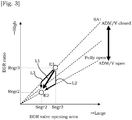
- Fig. 8 is a timing chart in a case in which the control routine of Fig. 7 is performed at the transient state in which the operating point moves from region E3 to region E2 as with Fig. 3 .
- the solid line in Fig. 8 shows the case in which the control routine is performed in the present embodiment.
- Fig. 8 shows the case in which the differential pressure generating valve 12 and the EGR valve 10 each independently start operation simultaneously, as the comparative example shown by the broken line.
- the differential pressure generating valve 12 actually starts operation after the EGR valve 10 starts operation, the time difference is only slight, and hence in Fig. 8 it is shown as simultaneously starting the operation.
- the controller 100 sets the EGR/V opening target change rate at which the opening of the EGR valve 10 decreases at a constant change rate (S220), and causes the EGR valve 10 to start operation (S230).
- the opening of the differential pressure generating valve 12 increases gradually from immediately after starting the operation of the differential pressure generating valve 12 (S240-S260). If the differential pressure generating valve 12 is made fully open step-wise together with the start of the operation, the EGR ratio decreases sharply as in the comparative example. In comparison, in the present embodiment, the opening of the differential pressure generating valve 12 is gradually increased, and thus can prevent the sudden change of the EGR ratio.
- Fig. 9 is a timing chart in a case in which the control routine of Fig. 7 is performed at the transient state in which the operating point moves from region E2 to region E3, opposite to Fig. 8 .
- the solid line shows the case in which the present embodiment is performed, and the broken line shows the comparative example.
- the controller 100 sets the EGR/V opening target change rate at which the opening of the EGR valve 10 increases at the constant change rate as shown (S220), and makes the EGR valve 10 start the operation (S230).
- the opening of the differential pressure generating valve 12 gradually decreases from immediately after starting the operation of the differential pressure generating valve 12 (S240-S260). If the differential pressure generating valve 12 is made to SA1 step-wise together with starting the operation, the EGR ratio increases sharply as in the comparative example. In comparison, in the present embodiment, the opening of the differential pressure generating valve 12 is reduced gradually, and thus the sudden change in the EGR ratio can be prevented.
- the controller 100 in the case of reducing the EGR ratio, the controller 100 starts to operate the EGR valve 10 in the closing direction in advance, and operates the differential pressure generating valve 12 in the opening direction in accordance with the opening of the EGR valve 10 in operation.
- the controller 100 starts to operate the EGR valve 10 in the opening direction in advance, and operates the differential pressure generating valve 12 in the closing direction in accordance with the opening of the EGR valve 10 in operation.
- the present embodiment is basically the same as First Embodiment, however a part of the EGR control routine differs. The following mainly describes the different points from First Embodiment.
- Fig. 10 is a flowchart showing the EGR control routine performed by the controller 100 of the present embodiment when the target EGR ratio changes. This control routine is repetitively performed in short intervals of, for example, around 10 milliseconds.
- Steps S300 to S330, S350 to S360 are the same as steps S100 to S130, S150 to S160 in Fig. 4 , and thus explanations thereof are omitted.
- step S340 the controller 100 calculates the opening area of the EGR valve 10 (EGR/V opening area) with Formula (1), and sets this.
- EGR / V opening area Basic EGR / V opening area ⁇ f ( ADM / V opening area )
- the basic EGR/V opening area of Formula (1) is an EGR/V opening area calculated from a relationship of the EGR/V opening area with the EGR ratio in a case of assuming the differential pressure generating valve 12 as any predetermined opening.
- the f (ADM/V opening area) in Formula (1) is a compensation item for compensating the basic EGR/V opening area in accordance with the opening of the differential pressure generating valve 12. Processes of the present steps are described with reference to Fig. 11 .
- Fig. 11 is a view for describing a state of the EGR ratio changing in the case in which the operating point changes from on the solid line A1 of region E3 to region E2, as with Fig. 3 .
- the EGR/V opening area in a case of assuming that the predetermined opening of the differential pressure generating valve 12 is fully opened is made to serve as the basic EGR/V opening area. That is to say, the relationship between the EGR/V opening area with the EGR ratio is the straight line A1 shown by the solid line in Fig. 11 , of when the differential pressure generating valve 12 is fully opened.
- the basic EGR/V opening area becomes Segr4'.
- the actual opening of the differential pressure generating valve 12 is SA4, and thus the relationship of the EGR ratio with the EGR/V opening area should become the solid line A2.
- the basic EGR/V opening area is compensated with the above-mentioned compensation item in accordance with the difference in inclination between the solid line A1 and the solid line A2, to obtain the EGR/V opening area Segr4.
- the predetermined opening of the differential pressure generating valve 12 at the time of setting the basic EGR/V opening area does not need to be fully opened.
- the present embodiment is basically the same as Second Embodiment, however a part of the EGR control routine differs. The following mainly describes the different points from Second Embodiment.
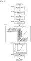
- Fig. 12 is a flowchart showing the EGR control routine performed by the controller 100 of the present embodiment when the target EGR ratio changes. This control routine is repetitively performed in short intervals of, for example, around 10 milliseconds.
- Steps S400 to S430, S450 to S460 are the same as steps S200 to S230, S250 to S260 in Fig. 7 , and thus explanations thereof are omitted.
- step S440 the controller 100 calculates the opening area of the differential pressure generating valve 12 (ADM/V opening area) with Formula (2), and sets this.
- ADM / V opening area Basic ADM / V opening area ⁇ f ( EGR / V opening area )
- the basic ADM/V opening area of Formula (2) is an ADM/V opening area calculated from a relationship of the ADM/V opening area with the EGR ratio in the case of assuming the EGR valve 10 as any predetermined opening.
- the f (EGR/V opening area) of Formula (2) is a compensation item for compensating the basic ADM/V opening area in accordance with the opening of the EGR valve 10. Processes of the present steps are described with reference to Fig. 13 .
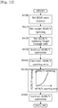
- Fig. 13 is a view for describing a state of the EGR ratio changing in the case in which the operating point changes from on the solid line A1 of region E3 to region E2, as with Fig. 3 .
- the ADM/V opening area in a case of assuming the predetermined opening of the EGR valve 10 as Segr 1 is made to serve as the basic EGR/V opening area. That is to say, the relationship of the ADM/V opening area with the EGR ratio is the straight line B1 shown by the solid line in Fig. 13 of when the opening of the EGR valve 10 is Segr1.
- the basic ADM/V opening area is Sadm4'.
- the actual opening of the EGR valve 10 is Segr4
- the relationship of the EGR ratio with the ADM/V opening area should become the solid line B2.
- the basic ADM/V opening area is compensated with the above-mentioned compensation item in accordance with the difference in inclination between the solid line B1 and the solid line B2, to obtain the ADM/V opening area Segr4.
- the predetermined opening of the EGR valve 10 at the time of setting the basic ADM/V opening area may be set as any value.
- the controller 100 has a configuration using the throttle valve 5 and the wastegate valve 8 to adjust the engine load, however it is not limited to this.
- the valve timing control mechanism 13 is of a configuration in which a valve lifted amount and the valve timing is variably controllable, the engine load can be adjusted with the valve timing control mechanism 13.
- the configuration capable of variably controlling the valve lifting amount and the valve timing is publicly known, and thus explanation thereof is omitted.
- the engine load is adjusted by the throttle valve 5, the wastegate valve 8 or the valve timing control mechanism 13, and thus the change in the opening of the differential pressure generating valve 12 and the EGR valve 10 will give no effect on the engine load. Therefore, accelerating performance will not decrease by performing the EGR control routine of the aforementioned embodiments.
Abstract
Description
- The present invention relates to exhaust gas recirculation control of an internal combustion engine that includes a turbo supercharger and an exhaust gas recirculation system.
- An exhaust gas recirculation (EGR: Exhaust Gas Recirculation) device is known, which causes a part of exhaust gas to recirculate into an intake passage, in order to prevent knocking and to achieve effects such as improvement in fuel economy due to reduction in pumping loss. Furthermore,
JP2012-7547A - This low-pressure loop EGR device includes a differential pressure generating valve for ensuring a differential pressure between the intake passage and an exhaust passage even in operating regions with low intake amounts. Furthermore, in the operating regions with low intake amounts, opening and closing of the EGR valve to adjust the amount of EGR gas is controlled in a state in which the differential pressure generating valve is controlled to a closing side. That is to say, the differential pressure is generated at the differential pressure generating valve, and the amount of EGR gas is adjusted by the EGR valve. Moreover, in the above document, an operated order of the differential pressure generating valve and the EGR valve are determined for the controlling, in a case in which the EGR ratio is to be changed equal to or more than a predetermined changing amount.
- When the EGR ratio changes, ignition timing thereof will also change in accordance with the EGR ratio. The ignition timing in this case is typically changed at a constant change rate, assuming that the EGR ratio will change from a current EGR ratio to a new target EGR ratio at a constant change rate.
- However, if the differential pressure generating valve and the EGR valve are manipulated to open and close separately as in the above document, it is impossible to avoid a sudden change in the EGR ratio. For example, when the EGR ratio is reduced, in the above-mentioned document, the EGR valve is controlled in the closing direction after the differential pressure generating valve is fully opened. According to this, the EGR ratio drops sharply when the differential pressure generating valve is made fully open. On the other hand, when the EGR ratio is increased, the above document controls the EGR valve to an opening in accordance with a target EGR ratio upon controlling the differential pressure generating valve in the closing direction. According to this, the EGR ratio increases sharply when the differential pressure generating valve is controlled in the closing direction.
- In contrast to the ignition timing changing at a constant change rate as described above, when the EGR ratio changes sharply, the ignition timing would not be an appropriate timing for the actual EGR ratio, and may cause deterioration in combustion stability.
- Accordingly, an object of the present invention is to change the EGR ratio without causing any deterioration in the combustion stability.
- According to one embodiment of this invention, an exhaust gas recirculation control method of an internal combustion engine, the internal combustion engine comprising: a turbo supercharger; an exhaust gas recirculation passage communicating an exhaust passage with an intake passage at a part upstream of a compressor of the turbo supercharger; an exhaust gas recirculating amount control valve disposed in the exhaust gas recirculation passage; a differential pressure generating valve disposed upstream of a merging portion of fresh air gas and exhaust gas in the intake passage; and a controller adapted to control an opening of the exhaust gas recirculation amount control valve and an opening of the differential pressure generating valve is provided. In the method, the controller cooperatively controls the opening of the exhaust gas recirculation amount control valve and the opening of the differential pressure generating valve to make an exhaust gas recirculation ratio change to a target exhaust gas recirculation ratio at a change rate that prevents abnormal combustion of the internal combustion engine.
-
- [
Fig. 1] Fig. 1 is a schematic diagram of an internal combustion engine system. - [
Fig. 2] Fig. 2 is an EGR map showing EGR ratios for each operating region. - [
Fig. 3] Fig. 3 is a view for describing a change history of the EGR ratio. - [
Fig. 4] Fig. 4 is a flowchart showing an EGR control routine of First Embodiment. - [
Fig. 5] Fig. 5 is a timing chart of a case in which the EGR ratio is reduced in First Embodiment. - [
Fig. 6] Fig. 6 is a timing chart of a case in which the EGR ratio is increased in First Embodiment. - [
Fig. 7] Fig. 7 is a flowchart showing the EGR control routine of Second Embodiment. - [
Fig. 8] Fig. 8 is a timing chart of a case in which the EGR ratio is reduced in Second Embodiment. - [
Fig. 9] Fig. 9 is a timing chart of a case in which the EGR ratio is increased in Second Embodiment. - [
Fig. 10] Fig. 10 is a flowchart showing the EGR control routine of Third Embodiment. - [
Fig. 11] Fig. 11 is a view for describing a calculation method of an opening area of an EGR valve in Third Embodiment. - [
Fig. 12] Fig. 12 is a flowchart showing the EGR control routine of Fourth Embodiment. - [
Fig. 13] Fig. 13 is a view for describing a calculation method of the opening area of a differential pressure generating valve in Fourth Embodiment. - The following describes embodiments of the present invention, with reference to the attached drawings.
-
Fig. 1 is a schematic diagram of a system employing the present embodiment. - An
intake passage 2 of aninternal combustion engine 1 disposes, in order from an upstream side of an intake flow, a differentialpressure generating valve 12, acompressor 4A of aturbo supercharger 4, and athrottle valve 5 for adjusting an engine load. The differentialpressure generating valve 12 and thethrottle valve 5 are valves that open and close by an electric motor, and are controlled by acontroller 100 later described.Fig. 1 shows butterfly valves as the differentialpressure generating valve 12 and thethrottle valve 5, however this may also be other types of valves. - An
exhaust passage 3 of theinternal combustion engine 1 disposes, in order from an upstream side of an exhaust flow, aturbine 4B of theturbo supercharger 4, and an exhaust gas purifying catalyst 6. The exhaust gas purifying catalyst 6 is, for example, a three-way catalyst. - The
internal combustion engine 1 includes abypass passage 7 that communicates a part of theexhaust passage 3 upstream of theturbine 4B with a part of theexhaust passage 3 downstream of theturbine 4B. Thebypass passage 7 disposes awastegate valve 8 that opens and closes thebypass passage 7. Thewastegate valve 8 is a valve that opens and closes by an electric motor, and is controlled by thecontroller 100 later described. When thewastegate valve 8 opens, a part of exhaust gas flows by bypassing theturbine 4B. Therefore, by controlling the opening of thewastegate valve 8, boost pressure can be adjusted. Namely, in an operating region in which thethrottle valve 5 cannot control the amount of the intake air due to the boost pressure exceeding air pressure, the engine load will be controlled by thewastegate valve 8. -
Fig. 1 shows a swing valve as thewastegate valve 8, however this may be other types of valves. - Moreover, the system includes an EGR device for recirculating a portion of the exhaust gas into the
intake passage 2. Hereinafter, the exhaust gas to be recirculated will be called EGR gas. - The EGR device is configured including an EGR
passage 9 that communicates theexhaust passage 3A at a part downstream of the exhaust gas purifying catalyst 6 with theintake passage 2 at a part upstream of thecompressor 4A, anEGR valve 10 that opens and closes theEGR passage 9, and anEGR cooler 11 that cools the exhaust gas passing through the EGRpassage 9. Namely, the EGR device is what is called a low-pressure loop EGR device. TheEGR valve 10 is a valve that opens and closes by an electric motor, and is controlled by thecontroller 100 later described.Fig. 1 shows a case of a butterfly valve serving as theEGR valve 10, however this may be other types of valves. The EGRcooler 11 may be any of either an air-cooled or a liquid-cooled type. - The
internal combustion engine 1 includes a valvetiming control mechanism 13 for changing a valve timing of the intake valve and the exhaust valve. A publicly known mechanism can be employed for the valvetiming control mechanism 13; for example, a mechanism to change a rotational phase with respect to a crankshaft of an intake camshaft is used. - The
controller 100 sets items such as a fuel injection amount, a fuel injection timing, an ignition timing, and an EGR ratio, on the basis of detected values from crank angle sensors, accelerator position sensors, intake pressure sensors, air flow meters, and like components not illustrated. Furthermore, on the basis of these, thecontroller 100 controls the opening and closing of the differentialpressure generating valve 12, thethrottle valve 5, theEGR valve 10, and thewastegate valve 8, and controls the valve timing by driving the valvetiming control mechanism 13. - Next describes the exhaust gas recirculation control (hereinafter, also called EGR control).
-
Fig. 2 is an EGR map showing the operating regions and EGR ratios that perform the EGR control. The horizontal axis inFig. 2 represents engine revolution speed, and the vertical axis represents engine load. The EGR ratio is a proportion of EGR gas to fresh air gas - The EGR region in
Fig. 2 is a region in which EGR control is performed. The EGR region is divided into three regions, E1, E2, and E3, in accordance with the EGR ratio. The EGR ratio is set higher as the revolution speed and load becomes lower. For example, region E1 is 10%, region E2 is 15%, and region E3 is 20%. - Solid lines A1 to A3 of region E3 are even opening lines of the differential
pressure generating valve 12. The opening of solid line A1 is defined as SA1, the opening of solid line A2 is defined as SA2, and the opening of solid line A3 is defined SA3. The sizes of the openings are SA1>SA2>SA3. In the low-pressure loop EGR device, parts of theintake passage 2 that are introduced with the EGR gas are mostly at air pressure; thus, the differential pressure between the intake side and the exhaust side of the EGR valve 10 (hereinafter, also called fore-and-aft differential pressure) is smaller than a conventional EGR device that introduces the EGR gas into a negative pressure part downstream of the throttle valve 5 (high-pressure loop EGR device). In particular, since the exhaust gas flow rate is low in the low revolution speed low load region and thus the pressure of the exhaust passage does not increase, the fore-and-aft differential pressure of theEGR valve 10 decreases. On this account, by controlling the differentialpressure generating valve 12 largely in the closing direction as the air intake amount decreases, the pressure downstream of the differentialpressure generating valve 12 is reduced to ensure the fore-and-aft differential pressure of theEGR valve 10. - The solid line A3 matches with an even fresh air amount line of an upper limit of a fresh air amount that receives no effect even when the differential
pressure generating valve 3 is controlled to the closing side. In regions in which the intake air amount is small as like the low revolution speed low load region, although no effect is given on the fresh air amount even when controlling the differentialpressure generating valve 12 to the closing side, if the intake air amount increases, pumping loss occurs in the differentialpressure generating valve 12 and the fresh air amount decreases. On this account, in regions E2 and E1 where it exceeds the upper limit of the fresh air amount at which no effect is given by controlling the differentialpressure generating valve 12 to the closing side, the differentialpressure generating valve 12 is fully opened. - In regions E1 and E2, the differential
pressure generating valve 12 is controlled to the fully opened state. This is because the pressure of the exhaust passage increases, and the fore-and-apt differential pressure of theEGR valve 10 develops sufficiently even when the differentialpressure generating valve 12 is fully open. - The
controller 100 reads in the engine revolution speed and the engine load as an engine operating state, and sets a target EGR ratio and a target opening of the differentialpressure generating valve 12 by referring to the map ofFig. 2 . Thecontroller 100 then sets a target opening area of theEGR valve 10 on the basis of the target EGR ratio, and controls the opening to achieve that opening area. The engine revolution speed is calculated from a detected value of the crank angle sensor not illustrated. The engine load may be calculated from a detected value of the air flow meter not illustrated, or may be calculated from a detected value of the accelerator position sensor not illustrated. - Excluding a transient state later described in which the EGR ratio changes, the EGR ratio is controlled by the opening of the
EGR valve 10. The differentialpressure generating valve 12 generates an environment in which the EGR ratio changes in accordance with the opening of theEGR valve 10, and does not directly control the EGR ratio. -
Fig. 3 is a view for describing a changing state of the EGR ratio in a case in which an operating point changes from on the solid line A1 of region E3 to region E2. The horizontal axis inFig. 3 represents the opening area of the EGR valve (EGR/V) 10, and the vertical axis represents the EGR ratio. Moreover, the broken lines inFig. 3 each show the opening of the differential pressure generating valve (ADM/V) 12. - When the operating point changes from region E3 to region E2, the EGR ratio changes from Regr3 to Regr2, the EGR/V opening area changes from Segr3 to Segr2, and the opening of the differential
pressure generating valve 12 changes from SA1 to fully opened. - At this time, by operating the
EGR valve 10 upon fully opening the differentialpressure generating valve 12, a change history in the EGR ratio becomes as shown as L2 inFig. 3 . On the other hand, by operating the differentialpressure generating valve 12 upon making the EGR/V opening area to Segr2, the change history in the EGR ratio becomes as shown as L3 inFig. 3 . - Either history includes a portion in which the EGR ratio sharply decreases. When the operating state changes the ignition timing will also change, however the ignition timing in the transition of change is set as generally assuming a change at a constant change rate from point E3 to point E2 in
Fig. 3 (history L1 inFig. 3 ). Therefore, if a change occurs including a part in which the EGR ratio sharply changes as like in history L2 and history L3, the combustion stability may deteriorate. For example, in history L2, the EGR ratio sharply decreases more than that of history L1 when the differentialpressure generating valve 12 is made fully open, and a situation occurs that the actual EGR ratio is lower than what the assumed EGR ratio is. In this situation, if ignited on the basis of history L1, namely at an ignition timing set on the presumption that more EGR gas is introduced, knocking may occur. Moreover, in history L3, a situation occurs that the EGR ratio is higher than history L1 until the differentialpressure generating valve 12 is fully opened. If ignited at the ignition timing set on the basis of history L1 in this situation, since more EGR gas is introduced than the assumed amount of EGR gas, the fire may extinct. - As described above, if the EGR ratio changes by history L2 and L3, the combustion stability may deteriorate. The same applies in a case in which the operating point changes from region E2 to region E3. Moreover, in a case of simultaneously starting operation of the differential
pressure generating valve 12 and theEGR valve 10 independently, a sudden change in EGR ratio will similarly occur. - Accordingly, in the present embodiment, the EGR ratio is changed as in history L1 by the following control.
-
Fig. 4 is a flowchart showing an EGR control routine performed by thecontroller 100 when the target EGR ratio changes. This control routine is repetitively performed in short intervals of, for example, around 10 milliseconds. - The present control routine cooperatively controls the differential
pressure generating valve 12 and theEGR valve 10 so that the change history in the EGR ratio becomes the aforementioned L1. The following describes in line with the steps in the flowchart. - In step S100, the
controller 100 sets the change history of the EGR ratio. Here, as in history L1 ofFig. 3 , a history is set without a part in which the EGR ratio sharply changes. - In step S110, the
controller 100 sets the target opening of the differential pressure generating valve 12 (target ADM/V opening) by searching the map shown inFig. 2 with the engine revolution speed and the engine load. This target ADM/V opening is a target opening at the operating point after movement. - In step S120, the
controller 100 sets a target value of an opening change rate from the current ADM/V opening to the target ADM/V opening (ADM/V opening target change rate). The ADM/V opening target change rate may be set to any value. The differentialpressure generating valve 12 will not be largely moved to the closing side to prevent occurrence of pumping loss, and thus a change rate that immediately achieves the target value may be set. - In step S130, the
controller 100 starts operating the differentialpressure generating valve 12 on the basis of the ADM/V opening target change rate. - In step S140, the
controller 100 sets the opening area of theEGR valve 10. Here, as shown, tables that set relationships of the EGR ratio with the opening area of theEGR valve 10 are created in advance for each opening of the differentialpressure generating valve 12 and stored in thecontroller 100, and the opening of theEGR valve 10 is set by referring to the table at the EGR ratio determined from the EGR ratio history and the opening of the differentialpressure generating valve 12. That is to say, in the present step, the opening area of theEGR valve 10 for making the EGR ratio in accordance with the EGR ratio history is set. - In step S150, the
controller 100 sets the opening of theEGR valve 10 by searching the illustrated table with the opening area of theEGR valve 10 set in step S140. The table used here is one in which the relationship of the opening area of theEGR valve 10 with the opening of theEGR valve 10 is investigated and created in advance, and is stored in thecontroller 100. - In step S160, the
controller 100 operates theEGR valve 10 on the basis of the opening of theEGR valve 10 set in step S150. -
Fig. 5 is a timing chart in a case in which the control routine ofFig. 4 is performed at a transient state in which the operating point moves from region E3 to region E2 as withFig. 3 . The solid line inFig. 5 shows a case in which the control routine is performed in the present embodiment. Moreover,Fig. 5 shows a case in which the differentialpressure generating valve 12 and theEGR valve 10 each independently start operation simultaneously, as a comparative example with the broken line. Although theEGR valve 10 actually starts operation after the differentialpressure generating valve 12 starts operation, the time difference is only slight, and hence inFig. 5 it is shown as simultaneously starting the operation. - When the operating point targeted in timing T1 is switched to region E2, the EGR ratio history that changes at a constant change rate is set as shown, and the target ADM/V opening is set to fully opened (S100, S110). In the present embodiment, the
controller 100 sets the ADM/V opening target change rate to one that makes the differentialpressure generating valve 12 fully open step-wise at timing T1 (S120), and starts operating the differential pressure generating valve 12 (S130). - The opening of the
EGR valve 10 increases immediately after starting the operation of theEGR valve 10, and then gradually decreases towards B2 (S140-S160). Immediately after starting the operation of theEGR valve 10, the EGR gas is made difficult to be introduced due to the differentialpressure generating valve 12 being fully opened, and thus when theEGR valve 10 is caused to operate towards B2 together with the start of operation, the EGR ratio decreases sharply as in the comparative example. In comparison, in the present embodiment, the effect caused by the differentialpressure generating valve 12 being made fully open is set off by increasing the opening of theEGR valve 10 immediately after starting the operation, and thus allows for changing the EGR ratio at the constant change rate. -
Fig. 6 is a timing chart in a case in which the control routine ofFig. 4 is performed at a transient state in which the operating point moves from region E2 to region E3, opposite toFig. 5 . As withFig. 5 , the solid line shows the case in which the present embodiment is performed, and the broken line shows the comparative example. - When the operating point targeted at timing T1 is switched to region E3, the EGR ratio history that changes at the constant change rate is set as shown, and the target ADM/V opening is set to SA1 (S100, S110). In the present embodiment, the
controller 100 sets the ADM/V opening target change rate that makes the differentialpressure generating valve 12 become SA1 step-wise at timing T1 (S120), and starts operating the differential pressure generating valve 12 (S130). - The opening of the
EGR valve 10 decreases immediately after starting the operation of theEGR valve 10, and then gradually increases (S140-S160). Immediately after starting the operation of theEGR valve 10, the EGR gas is made easily introduced due to the opening of the differentialpressure generating valve 12 becoming SA1, and thus when theEGR valve 10 is caused to operate towards B1 together with the start of operation, the EGR ratio increases sharply as in the comparative example. In comparison, in the present embodiment, the effect caused by the opening of the differentialpressure generating valve 12 becoming small is set off by reducing the opening of theEGR valve 10 immediately after starting the operation, and thus can allow for changing the EGR ratio at the constant change rate. - In the EGR control described above, the EGR ratio history in which the EGR ratio changes at the constant change rate is set, however it is not limited to this. As long as the change rate is of a range in which no abnormal combustion of the
internal combustion engine 1 such as knocking or extinction occur, the change rate can be changed in the middle. - As described above, in the present embodiment, the
controller 100 cooperatively controls the opening of the EGR valve 10 (exhaust gas recirculation control valve) and the opening of the differentialpressure generating valve 12, and causes the EGR ratio (exhaust gas recirculation ratio) to change to the target exhaust gas recirculation ratio at the change rate that prevents the abnormal combustion of theinternal combustion engine 1. Accordingly, the sudden change in the EGR ratio can be prevented, and thus the EGR ratio can be changed without deteriorating the combustion stability. - In the present embodiment, in the case of reducing the EGR ratio, the
controller 100 starts to operate the differentialpressure generating valve 12 in the opening direction in advance, and operates theEGR valve 10 in the closing direction in accordance with the opening of the differentialpressure generating valve 12 in operation. On the other hand, in the case of increasing the EGR ratio, thecontroller 100 starts to operate the differentialpressure generating valve 12 in the closing direction in advance, and operates theEGR valve 10 in the opening direction in accordance with the opening of the differentialpressure generating valve 12 in operation. As described above, by starting to operate the differentialpressure generating valve 12 in advance and performing cooperative control that makes theEGR valve 10 operate in accordance with the opening of the differentialpressure generating valve 12, it is possible prevent the sudden change in the EGR ratio. - The present embodiment is similar to First Embodiment in a point that at the transient state in which the EGR ratio changes, the sudden change in the EGR ratio is prevented by cooperatively controlling the differential
pressure generating valve 12 and theEGR valve 10. However, the order that the differentialpressure generating valve 12 and theEGR valve 10 are operated is different from First Embodiment. The following mainly explains the points different from First Embodiment. -
Fig. 7 is a flowchart showing the EGR control routine performed by thecontroller 100 of the present embodiment when the target EGR ratio changes. This control routine is repetitively performed in short intervals of, for example, around 10 milliseconds. - In step S200, the
controller 100 sets the EGR ratio history. This step is the same as step S100 inFig. 4 , and thus explanation thereof is omitted. - In step S210, the
controller 100 sets the target opening of the EGR valve 10 (target EGR/V opening) by searching the map shown inFig. 2 with the engine revolution speed and the engine load. This target EGR/V opening is a target opening at the operating point after movement. - In step S220, the
controller 100 sets a target value of an opening change rate from the current EGR/V opening to the target EGR/V opening (EGR/V opening target change rate). The EGR/V opening target change rate may be set to any value. - In step S230, the
controller 100 starts operating theEGR valve 10 on the basis of the EGR/V opening target change rate. - In step S240, the
controller 100 sets the opening area of the differentialpressure generating valve 12. Here, as shown, tables that set a relationship of the EGR ratio with the opening area of the differential pressure generating valve 12 (ADM/V opening area) is created in advance for each opening of theEGR valve 10 and is stored in thecontroller 100, and the opening of the differentialpressure generating valve 12 is set by referring to the table at the EGR ratio determined from the EGR ratio history and the opening of theEGR valve 10. That is to say, in the present step, the opening area of the differentialpressure generating valve 12 for making the EGR ratio in accordance with the EGR ratio history is set. - In
step 250, thecontroller 100 sets the opening of the differentialpressure generating valve 12 by searching the illustrated table with the opening area of the differentialpressure generating valve 12 set in step S240. The table used here is one in which the relationship of the opening area of the differentialpressure generating valve 12 with the opening of the differentialpressure generating valve 12 is investigated and created in advance, and is stored in thecontroller 100. - In step S260, the
controller 100 operates the differentialpressure generating valve 12 on the basis of the opening of the differentialpressure generating valve 12 set in step S250. -
Fig. 8 is a timing chart in a case in which the control routine ofFig. 7 is performed at the transient state in which the operating point moves from region E3 to region E2 as withFig. 3 . The solid line inFig. 8 shows the case in which the control routine is performed in the present embodiment. Moreover,Fig. 8 shows the case in which the differentialpressure generating valve 12 and theEGR valve 10 each independently start operation simultaneously, as the comparative example shown by the broken line. Although the differentialpressure generating valve 12 actually starts operation after theEGR valve 10 starts operation, the time difference is only slight, and hence inFig. 8 it is shown as simultaneously starting the operation. - When the operating point targeted at timing T1 is switched to region E2, the EGR ratio history that changes at the constant change rate is set as shown, and the target EGR/V opening is set to B1 (S200, S210). In the present embodiment, the
controller 100 sets the EGR/V opening target change rate at which the opening of theEGR valve 10 decreases at a constant change rate (S220), and causes theEGR valve 10 to start operation (S230). - The opening of the differential
pressure generating valve 12 increases gradually from immediately after starting the operation of the differential pressure generating valve 12 (S240-S260). If the differentialpressure generating valve 12 is made fully open step-wise together with the start of the operation, the EGR ratio decreases sharply as in the comparative example. In comparison, in the present embodiment, the opening of the differentialpressure generating valve 12 is gradually increased, and thus can prevent the sudden change of the EGR ratio. -
Fig. 9 is a timing chart in a case in which the control routine ofFig. 7 is performed at the transient state in which the operating point moves from region E2 to region E3, opposite toFig. 8 . As withFig. 8 , the solid line shows the case in which the present embodiment is performed, and the broken line shows the comparative example. - When the operating point targeted in timing T1 is switched to region E3, the EGR ratio history that changes at the constant change rate is set as shown, and the target EGR/V opening is set to B2 (S200, S210). In the present embodiment, the
controller 100 sets the EGR/V opening target change rate at which the opening of theEGR valve 10 increases at the constant change rate as shown (S220), and makes theEGR valve 10 start the operation (S230). - The opening of the differential
pressure generating valve 12 gradually decreases from immediately after starting the operation of the differential pressure generating valve 12 (S240-S260). If the differentialpressure generating valve 12 is made to SA1 step-wise together with starting the operation, the EGR ratio increases sharply as in the comparative example. In comparison, in the present embodiment, the opening of the differentialpressure generating valve 12 is reduced gradually, and thus the sudden change in the EGR ratio can be prevented. - As described above, in the present embodiment, in the case of reducing the EGR ratio, the
controller 100 starts to operate theEGR valve 10 in the closing direction in advance, and operates the differentialpressure generating valve 12 in the opening direction in accordance with the opening of theEGR valve 10 in operation. On the other hand, in the case of increasing the EGR ratio, thecontroller 100 starts to operate theEGR valve 10 in the opening direction in advance, and operates the differentialpressure generating valve 12 in the closing direction in accordance with the opening of theEGR valve 10 in operation. As described above, by starting to operate theEGR valve 10 in advance and performing cooperative control that makes the differentialpressure generating valve 12 operate in accordance with the opening of theEGR valve 10, it is possible prevent the sudden change in the EGR ratio. - The present embodiment is basically the same as First Embodiment, however a part of the EGR control routine differs. The following mainly describes the different points from First Embodiment.
-
Fig. 10 is a flowchart showing the EGR control routine performed by thecontroller 100 of the present embodiment when the target EGR ratio changes. This control routine is repetitively performed in short intervals of, for example, around 10 milliseconds. - Steps S300 to S330, S350 to S360 are the same as steps S100 to S130, S150 to S160 in
Fig. 4 , and thus explanations thereof are omitted. - In step S340, the
controller 100 calculates the opening area of the EGR valve 10 (EGR/V opening area) with Formula (1), and sets this.
- The basic EGR/V opening area of Formula (1) is an EGR/V opening area calculated from a relationship of the EGR/V opening area with the EGR ratio in a case of assuming the differential
pressure generating valve 12 as any predetermined opening. The f (ADM/V opening area) in Formula (1) is a compensation item for compensating the basic EGR/V opening area in accordance with the opening of the differentialpressure generating valve 12. Processes of the present steps are described with reference toFig. 11 . -
Fig. 11 is a view for describing a state of the EGR ratio changing in the case in which the operating point changes from on the solid line A1 of region E3 to region E2, as withFig. 3 . Here, the EGR/V opening area in a case of assuming that the predetermined opening of the differentialpressure generating valve 12 is fully opened is made to serve as the basic EGR/V opening area. That is to say, the relationship between the EGR/V opening area with the EGR ratio is the straight line A1 shown by the solid line inFig. 11 , of when the differentialpressure generating valve 12 is fully opened. - For example, when the EGR ratio calculated from the history L1 of the change in EGR ratio and the opening SA4 of the differential
pressure generating valve 12 is Regr4, the basic EGR/V opening area becomes Segr4'. At this time, the actual opening of the differentialpressure generating valve 12 is SA4, and thus the relationship of the EGR ratio with the EGR/V opening area should become the solid line A2. On this account, the basic EGR/V opening area is compensated with the above-mentioned compensation item in accordance with the difference in inclination between the solid line A1 and the solid line A2, to obtain the EGR/V opening area Segr4. - The predetermined opening of the differential
pressure generating valve 12 at the time of setting the basic EGR/V opening area does not need to be fully opened. - Even by calculating the EGR/V opening area as described above, the same effect is obtained as with First Embodiment.
- The present embodiment is basically the same as Second Embodiment, however a part of the EGR control routine differs. The following mainly describes the different points from Second Embodiment.
-
Fig. 12 is a flowchart showing the EGR control routine performed by thecontroller 100 of the present embodiment when the target EGR ratio changes. This control routine is repetitively performed in short intervals of, for example, around 10 milliseconds. - Steps S400 to S430, S450 to S460 are the same as steps S200 to S230, S250 to S260 in
Fig. 7 , and thus explanations thereof are omitted. - In step S440, the
controller 100 calculates the opening area of the differential pressure generating valve 12 (ADM/V opening area) with Formula (2), and sets this.
- The basic ADM/V opening area of Formula (2) is an ADM/V opening area calculated from a relationship of the ADM/V opening area with the EGR ratio in the case of assuming the
EGR valve 10 as any predetermined opening. The f (EGR/V opening area) of Formula (2) is a compensation item for compensating the basic ADM/V opening area in accordance with the opening of theEGR valve 10. Processes of the present steps are described with reference toFig. 13 . -
Fig. 13 is a view for describing a state of the EGR ratio changing in the case in which the operating point changes from on the solid line A1 of region E3 to region E2, as withFig. 3 . Here, the ADM/V opening area in a case of assuming the predetermined opening of theEGR valve 10 asSegr 1 is made to serve as the basic EGR/V opening area. That is to say, the relationship of the ADM/V opening area with the EGR ratio is the straight line B1 shown by the solid line inFig. 13 of when the opening of theEGR valve 10 is Segr1. - For example, when the EGR ratio calculated from the history L1 of the change in EGR ratio and the opening Segr4 of the
EGR valve 10 is Regr4, the basic ADM/V opening area is Sadm4'. At this time, the actual opening of theEGR valve 10 is Segr4, and thus the relationship of the EGR ratio with the ADM/V opening area should become the solid line B2. On this account, the basic ADM/V opening area is compensated with the above-mentioned compensation item in accordance with the difference in inclination between the solid line B1 and the solid line B2, to obtain the ADM/V opening area Segr4. The predetermined opening of theEGR valve 10 at the time of setting the basic ADM/V opening area may be set as any value. - Even by calculating the ADM/V opening area as described above, the same effect as with Second Embodiment is obtainable.
- In the above Embodiments, the
controller 100 has a configuration using thethrottle valve 5 and thewastegate valve 8 to adjust the engine load, however it is not limited to this. For example, as long as the valvetiming control mechanism 13 is of a configuration in which a valve lifted amount and the valve timing is variably controllable, the engine load can be adjusted with the valvetiming control mechanism 13. The configuration capable of variably controlling the valve lifting amount and the valve timing is publicly known, and thus explanation thereof is omitted. - The engine load is adjusted by the
throttle valve 5, thewastegate valve 8 or the valvetiming control mechanism 13, and thus the change in the opening of the differentialpressure generating valve 12 and theEGR valve 10 will give no effect on the engine load. Therefore, accelerating performance will not decrease by performing the EGR control routine of the aforementioned embodiments. - The embodiments of the present invention are described above, however the present embodiments merely show one portion of the applications of the present invention, and do not intend to limit the technical scope of the present invention to the specific configurations in the above embodiments.
Claims (10)
- An exhaust gas recirculation control method of an internal combustion engine, the internal combustion engine comprising:a turbo supercharger;an exhaust gas recirculation passage communicating an exhaust passage with an intake passage at a part upstream of a compressor of the turbo supercharger;an exhaust gas recirculating amount control valve disposed in the exhaust gas recirculation passage;a differential pressure generating valve disposed upstream of a merging portion of fresh air gas and exhaust gas in the intake passage; anda controller adapted to control an opening of the exhaust gas recirculation amount control valve and an opening of the differential pressure generating valve,wherein in the method,the controller cooperatively controls the opening of the exhaust gas recirculation amount control valve and the opening of the differential pressure generating valve to make an exhaust gas recirculation ratio change to a target exhaust gas recirculation ratio at a change rate that prevents abnormal combustion of the internal combustion engine.
- The exhaust gas recirculation control method according to claim 1, wherein
the controller, as the cooperative control,
starts operating one of the exhaust gas recirculation amount control valve or the differential pressure generating valve in advance on the basis of the target exhaust gas recirculation ratio; and
operates the other one of the exhaust gas recirculation amount control valve or the differential pressure generating valve in accordance with the opening of the one of the exhaust gas recirculation amount control valve or the differential pressure generating valve in operation. - The exhaust gas recirculation control method according to claim 2, wherein
in a case of reducing the exhaust gas recirculation ratio, the controller starts operating the differential pressure generating valve in an opening direction in advance; and
operates the exhaust gas recirculation amount control valve in a closing direction in accordance with the opening of the differential pressure generating valve in operation. - The exhaust gas recirculation control method according to claim 2, wherein
in a case of reducing the exhaust gas recirculation ratio, the controller
starts operating the exhaust gas recirculation amount control valve in a closing direction in advance; and
operates the differential pressure generating valve in an opening direction in accordance with the opening of the exhaust gas recirculation amount control valve in operation. - The exhaust gas recirculation control method according to claim 2, wherein
in a case of increasing the exhaust gas recirculation ratio, the controller
starts operating the differential pressure generating valve in a closing direction in advance; and
operates the exhaust gas recirculation amount control valve in an opening direction in accordance with the opening of the differential pressure generating valve in operation. - The exhaust gas recirculation control method according to claim 2, wherein
in a case of increasing the exhaust gas recirculation ratio, the controller
starts operating the exhaust gas recirculation amount control valve in an opening direction in advance; and
operates the differential pressure generating valve in a closing direction in accordance with the opening of the exhaust gas recirculation amount control valve in operation. - The exhaust gas recirculation control method according to any one of claims 1 to 6, wherein
the internal combustion engine comprises a throttle valve disposed downstream of the differential pressure generating valve in the intake passage, and
the controller adjusts a load on the internal combustion engine by controlling an opening of the throttle valve. - The exhaust gas recirculation control method according to claim 7, wherein
the internal combustion engine comprises a wastegate valve adapted to open and close a bypass passage that bypasses a turbine of the turbo supercharger, and
the controller adjusts the load on the internal combustion engine by controlling the wastegate valve. - The exhaust gas recirculation control method according to claim 7, wherein
the internal combustion engine comprises a valve timing control mechanism adapted to change a valve timing, and
the controller adjusts the load on the internal combustion engine by controlling the valve timing control mechanism. - An exhaust gas recirculation control device of an internal combustion engine, the internal combustion engine comprising:a turbo supercharger;an exhaust gas recirculation passage communicating an exhaust passage with an intake passage at a part upstream of a compressor of the turbo supercharger;an exhaust gas recirculating amount control valve disposed in the exhaust gas recirculation passage;a differential pressure generating valve disposed upstream of a merging portion of fresh air gas and exhaust gas in the intake passage; anda controller adapted to control an opening of the exhaust gas recirculation amount control valve and an opening of the differential pressure generating valve,wherein in the device,the controller cooperatively controls the opening of the exhaust gas recirculation amount control valve and the opening of the differential pressure generating valve to make an exhaust gas recirculation ratio change to a target exhaust gas recirculation ratio at a change rate that prevents abnormal combustion of the internal combustion engine.
Applications Claiming Priority (1)
| Application Number | Priority Date | Filing Date | Title |
|---|---|---|---|
| PCT/JP2015/075352 WO2017042868A1 (en) | 2015-09-07 | 2015-09-07 | Exhaust gas recirculation control method and exhaust gas recirculation control device |
Publications (3)
| Publication Number | Publication Date |
|---|---|
| EP3348818A1 true EP3348818A1 (en) | 2018-07-18 |
| EP3348818A4 EP3348818A4 (en) | 2018-09-12 |
| EP3348818B1 EP3348818B1 (en) | 2021-11-24 |
Family
ID=58239317
Family Applications (1)
| Application Number | Title | Priority Date | Filing Date |
|---|---|---|---|
| EP15903534.4A Active EP3348818B1 (en) | 2015-09-07 | 2015-09-07 | Exhaust gas recirculation control method and exhaust gas recirculation control device |
Country Status (11)
| Country | Link |
|---|---|
| US (1) | US10634075B2 (en) |
| EP (1) | EP3348818B1 (en) |
| JP (1) | JP6460247B2 (en) |
| KR (1) | KR101951613B1 (en) |
| CN (1) | CN108026846B (en) |
| BR (1) | BR112018004551B1 (en) |
| CA (1) | CA2997893C (en) |
| MX (1) | MX2018002814A (en) |
| MY (1) | MY192725A (en) |
| RU (1) | RU2684057C1 (en) |
| WO (1) | WO2017042868A1 (en) |
Cited By (2)
| Publication number | Priority date | Publication date | Assignee | Title |
|---|---|---|---|---|
| EP3351773A4 (en) * | 2015-09-18 | 2018-09-12 | Nissan Motor Co., Ltd. | Control device for internal combustion engine and control method for internal combustion engine |
| EP3351774A4 (en) * | 2015-09-18 | 2018-09-12 | Nissan Motor Co., Ltd. | Control device for internal combustion engine and control method for internal combustion engine |
Families Citing this family (7)
| Publication number | Priority date | Publication date | Assignee | Title |
|---|---|---|---|---|
| JP6691498B2 (en) * | 2017-03-17 | 2020-04-28 | 本田技研工業株式会社 | Control device for internal combustion engine |
| CN107084055B (en) * | 2017-03-30 | 2020-03-31 | 宁波吉利罗佑发动机零部件有限公司 | Throttle valve device for vehicle engine |
| CN111720204B (en) * | 2019-03-21 | 2021-08-17 | 上海汽车集团股份有限公司 | Engine control method and device |
| WO2021044178A1 (en) * | 2019-09-06 | 2021-03-11 | 日産自動車株式会社 | Egr control method and egr control apparatus |
| CN112901377B (en) * | 2021-02-10 | 2022-04-01 | 东风汽车集团股份有限公司 | Method for determining activation state of mixing valve of low-pressure EGR system |
| JP2023053473A (en) * | 2021-10-01 | 2023-04-13 | 株式会社Subaru | Intake/exhaust system |
| CN114962023B (en) * | 2022-06-29 | 2023-04-14 | 东风汽车集团股份有限公司 | EGR valve control method of low-pressure EGR system |
Family Cites Families (17)
| Publication number | Priority date | Publication date | Assignee | Title |
|---|---|---|---|---|
| JPH0388024A (en) | 1989-08-31 | 1991-04-12 | Koufu Nippon Denki Kk | Arithmetic unit for vector floating point |
| JP3888024B2 (en) | 2000-03-31 | 2007-02-28 | 三菱自動車工業株式会社 | Exhaust gas recirculation device |
| JP2010138734A (en) | 2008-12-10 | 2010-06-24 | Nissan Motor Co Ltd | Control device for internal combustion engine |
| CN101526042B (en) * | 2008-12-23 | 2011-07-06 | 天津大学 | Electronic control method of variable gas inlet and exhaust system of compression ignition engine |
| ITBO20090702A1 (en) | 2009-10-28 | 2011-04-28 | Magneti Marelli Spa | MIXER DEVICE FOR A LOW-PRESSURE ENGINE EGR SYSTEM WITH INTERNAL COMBUSTION |
| JP5472318B2 (en) * | 2009-12-08 | 2014-04-16 | トヨタ自動車株式会社 | Exhaust gas purification system for internal combustion engine |
| JP5506567B2 (en) * | 2010-06-25 | 2014-05-28 | ダイハツ工業株式会社 | Internal combustion engine |
| US9228538B2 (en) | 2011-05-19 | 2016-01-05 | Toyota Jidosha Kabushiki Kaisha | Internal combustion engine control apparatus |
| JP5854662B2 (en) * | 2011-06-28 | 2016-02-09 | 三菱重工業株式会社 | Control device and method for internal combustion engine |
| WO2013069427A1 (en) * | 2011-11-10 | 2013-05-16 | 本田技研工業株式会社 | Internal combustion engine intake control apparatus |
| US9587590B2 (en) | 2012-01-17 | 2017-03-07 | International Engine Intellectual Property Company, Llc. | Coordinating variable valve actuation and turbocharger operation in an internal combustion engine |
| JP5871654B2 (en) * | 2012-02-28 | 2016-03-01 | ダイハツ工業株式会社 | Control device |
| RU2599685C1 (en) * | 2013-02-01 | 2016-10-10 | Ниссан Мотор Ко., Лтд. | Exhaust gas recirculation control device and method of controlling exhaust gas recirculation for internal combustion engine |
| JP5716764B2 (en) | 2013-02-05 | 2015-05-13 | 株式会社デンソー | Engine control device |
| CN105102801A (en) | 2013-03-15 | 2015-11-25 | 博格华纳公司 | Low pressure exhaust gas recirculation module cross-reference to related applications |
| US9482189B2 (en) * | 2013-09-19 | 2016-11-01 | Ford Global Technologies, Llc | Methods and systems for an intake oxygen sensor |
| JP2015161174A (en) * | 2014-02-26 | 2015-09-07 | 愛三工業株式会社 | Supercharging device for engine |
-
2015
- 2015-09-07 MX MX2018002814A patent/MX2018002814A/en unknown
- 2015-09-07 BR BR112018004551-9A patent/BR112018004551B1/en active IP Right Grant
- 2015-09-07 JP JP2017538492A patent/JP6460247B2/en active Active
- 2015-09-07 MY MYPI2018700843A patent/MY192725A/en unknown
- 2015-09-07 EP EP15903534.4A patent/EP3348818B1/en active Active
- 2015-09-07 KR KR1020187006850A patent/KR101951613B1/en active IP Right Grant
- 2015-09-07 US US15/757,557 patent/US10634075B2/en active Active
- 2015-09-07 WO PCT/JP2015/075352 patent/WO2017042868A1/en active Application Filing
- 2015-09-07 CN CN201580082982.6A patent/CN108026846B/en active Active
- 2015-09-07 CA CA2997893A patent/CA2997893C/en active Active
- 2015-09-07 RU RU2018108191A patent/RU2684057C1/en active
Cited By (4)
| Publication number | Priority date | Publication date | Assignee | Title |
|---|---|---|---|---|
| EP3351773A4 (en) * | 2015-09-18 | 2018-09-12 | Nissan Motor Co., Ltd. | Control device for internal combustion engine and control method for internal combustion engine |
| EP3351774A4 (en) * | 2015-09-18 | 2018-09-12 | Nissan Motor Co., Ltd. | Control device for internal combustion engine and control method for internal combustion engine |
| US10450974B2 (en) | 2015-09-18 | 2019-10-22 | Nissan Motor Co., Ltd. | Control device for internal combustion engine and control method for internal combustion engine |
| US10495007B2 (en) | 2015-09-18 | 2019-12-03 | Nissan Motor Co., Ltd. | Control device for internal combustion engine and control method for internal combustion engine |
Also Published As
| Publication number | Publication date |
|---|---|
| MY192725A (en) | 2022-09-05 |
| CN108026846B (en) | 2021-03-23 |
| RU2684057C1 (en) | 2019-04-03 |
| WO2017042868A1 (en) | 2017-03-16 |
| CA2997893A1 (en) | 2017-03-16 |
| KR20180039143A (en) | 2018-04-17 |
| KR101951613B1 (en) | 2019-02-22 |
| EP3348818B1 (en) | 2021-11-24 |
| BR112018004551A2 (en) | 2018-10-09 |
| US10634075B2 (en) | 2020-04-28 |
| JPWO2017042868A1 (en) | 2018-07-19 |
| CN108026846A (en) | 2018-05-11 |
| US20180245528A1 (en) | 2018-08-30 |
| JP6460247B2 (en) | 2019-01-30 |
| CA2997893C (en) | 2022-08-30 |
| EP3348818A4 (en) | 2018-09-12 |
| MX2018002814A (en) | 2018-06-15 |
| BR112018004551B1 (en) | 2022-07-26 |
Similar Documents
| Publication | Publication Date | Title |
|---|---|---|
| CA2997893C (en) | Exhaust gas recirculation control method and exhaust gas recirculation control device | |
| EP1375876B1 (en) | Apparatus and method for controlling EGR in an engine | |
| JP4534514B2 (en) | Diesel engine control device | |
| EP2122150B1 (en) | Exhaust gas recirculation system for internal combustion engine and method for controlling the same | |
| JP4301295B2 (en) | EGR system for internal combustion engine | |
| JP3918402B2 (en) | Diesel engine control device | |
| JP4254606B2 (en) | Multistage turbocharging system for internal combustion engines | |
| EP2884078B1 (en) | Control device for diesel engine | |
| WO2012157108A1 (en) | Internal combustion engine control apparatus | |
| EP3511551B1 (en) | Control method and control device for internal combustion engine | |
| US10526987B2 (en) | Exhaust purification device of engine | |
| JP6141795B2 (en) | Internal combustion engine | |
| US20160319755A1 (en) | Control system of internal combustion engine | |
| JP7433328B2 (en) | EGR control method and EGR control device | |
| JP2005299570A (en) | Premixed combustion control system for compression ignition internal combustion engine | |
| JP3929712B2 (en) | EGR valve control method and apparatus | |
| US11680533B2 (en) | Method of estimating actual EGR ratio in EGR system and EGR system | |
| JP2018131961A (en) | Control device and control method | |
| JP5206514B2 (en) | Exhaust gas recirculation device for internal combustion engine | |
| JP4225221B2 (en) | Supercharging pressure control system for internal combustion engine | |
| EP3744962A1 (en) | Internal combustion engine control method and internal combustion engine control device | |
| JP2018135769A (en) | Internal combustion engine |
Legal Events
| Date | Code | Title | Description |
|---|---|---|---|
| STAA | Information on the status of an ep patent application or granted ep patent |
Free format text: STATUS: THE INTERNATIONAL PUBLICATION HAS BEEN MADE |
|
| PUAI | Public reference made under article 153(3) epc to a published international application that has entered the european phase |
Free format text: ORIGINAL CODE: 0009012 |
|
| STAA | Information on the status of an ep patent application or granted ep patent |
Free format text: STATUS: REQUEST FOR EXAMINATION WAS MADE |
|
| 17P | Request for examination filed |
Effective date: 20180312 |
|
| AK | Designated contracting states |
Kind code of ref document: A1 Designated state(s): AL AT BE BG CH CY CZ DE DK EE ES FI FR GB GR HR HU IE IS IT LI LT LU LV MC MK MT NL NO PL PT RO RS SE SI SK SM TR |
|
| AX | Request for extension of the european patent |
Extension state: BA ME |
|
| A4 | Supplementary search report drawn up and despatched |
Effective date: 20180816 |
|
| RIC1 | Information provided on ipc code assigned before grant |
Ipc: F02D 41/00 20060101ALI20180809BHEP Ipc: F02D 23/00 20060101AFI20180809BHEP Ipc: F02M 26/10 20160101ALI20180809BHEP Ipc: F02M 26/06 20160101ALI20180809BHEP Ipc: F02M 26/64 20160101ALI20180809BHEP Ipc: F02D 21/08 20060101ALI20180809BHEP |
|
| DAV | Request for validation of the european patent (deleted) | ||
| DAX | Request for extension of the european patent (deleted) | ||
| STAA | Information on the status of an ep patent application or granted ep patent |
Free format text: STATUS: EXAMINATION IS IN PROGRESS |
|
| 17Q | First examination report despatched |
Effective date: 20200218 |
|
| STAA | Information on the status of an ep patent application or granted ep patent |
Free format text: STATUS: EXAMINATION IS IN PROGRESS |
|
| RIC1 | Information provided on ipc code assigned before grant |
Ipc: F02D 23/02 20060101ALI20210623BHEP Ipc: F02B 37/18 20060101ALI20210623BHEP Ipc: F02D 41/24 20060101ALI20210623BHEP Ipc: F02M 26/64 20160101ALI20210623BHEP Ipc: F02M 26/10 20160101ALI20210623BHEP Ipc: F02M 26/06 20160101ALI20210623BHEP Ipc: F02D 41/00 20060101ALI20210623BHEP Ipc: F02D 21/08 20060101ALI20210623BHEP Ipc: F02D 23/00 20060101AFI20210623BHEP |
|
| GRAP | Despatch of communication of intention to grant a patent |
Free format text: ORIGINAL CODE: EPIDOSNIGR1 |
|
| STAA | Information on the status of an ep patent application or granted ep patent |
Free format text: STATUS: GRANT OF PATENT IS INTENDED |
|
| INTG | Intention to grant announced |
Effective date: 20210903 |
|
| GRAS | Grant fee paid |
Free format text: ORIGINAL CODE: EPIDOSNIGR3 |
|
| GRAA | (expected) grant |
Free format text: ORIGINAL CODE: 0009210 |
|
| STAA | Information on the status of an ep patent application or granted ep patent |
Free format text: STATUS: THE PATENT HAS BEEN GRANTED |
|
| AK | Designated contracting states |
Kind code of ref document: B1 Designated state(s): AL AT BE BG CH CY CZ DE DK EE ES FI FR GB GR HR HU IE IS IT LI LT LU LV MC MK MT NL NO PL PT RO RS SE SI SK SM TR |
|
| REG | Reference to a national code |
Ref country code: GB Ref legal event code: FG4D |
|
| REG | Reference to a national code |
Ref country code: AT Ref legal event code: REF Ref document number: 1450038 Country of ref document: AT Kind code of ref document: T Effective date: 20211215 |
|
| REG | Reference to a national code |
Ref country code: DE Ref legal event code: R096 Ref document number: 602015075324 Country of ref document: DE |
|
| REG | Reference to a national code |
Ref country code: IE Ref legal event code: FG4D |
|
| REG | Reference to a national code |
Ref country code: LT Ref legal event code: MG9D |
|
| REG | Reference to a national code |
Ref country code: NL Ref legal event code: MP Effective date: 20211124 |
|
| REG | Reference to a national code |
Ref country code: AT Ref legal event code: MK05 Ref document number: 1450038 Country of ref document: AT Kind code of ref document: T Effective date: 20211124 |
|
| PG25 | Lapsed in a contracting state [announced via postgrant information from national office to epo] |
Ref country code: RS Free format text: LAPSE BECAUSE OF FAILURE TO SUBMIT A TRANSLATION OF THE DESCRIPTION OR TO PAY THE FEE WITHIN THE PRESCRIBED TIME-LIMIT Effective date: 20211124 Ref country code: LT Free format text: LAPSE BECAUSE OF FAILURE TO SUBMIT A TRANSLATION OF THE DESCRIPTION OR TO PAY THE FEE WITHIN THE PRESCRIBED TIME-LIMIT Effective date: 20211124 Ref country code: FI Free format text: LAPSE BECAUSE OF FAILURE TO SUBMIT A TRANSLATION OF THE DESCRIPTION OR TO PAY THE FEE WITHIN THE PRESCRIBED TIME-LIMIT Effective date: 20211124 Ref country code: BG Free format text: LAPSE BECAUSE OF FAILURE TO SUBMIT A TRANSLATION OF THE DESCRIPTION OR TO PAY THE FEE WITHIN THE PRESCRIBED TIME-LIMIT Effective date: 20220224 Ref country code: AT Free format text: LAPSE BECAUSE OF FAILURE TO SUBMIT A TRANSLATION OF THE DESCRIPTION OR TO PAY THE FEE WITHIN THE PRESCRIBED TIME-LIMIT Effective date: 20211124 |
|
| PG25 | Lapsed in a contracting state [announced via postgrant information from national office to epo] |
Ref country code: IS Free format text: LAPSE BECAUSE OF FAILURE TO SUBMIT A TRANSLATION OF THE DESCRIPTION OR TO PAY THE FEE WITHIN THE PRESCRIBED TIME-LIMIT Effective date: 20220324 Ref country code: SE Free format text: LAPSE BECAUSE OF FAILURE TO SUBMIT A TRANSLATION OF THE DESCRIPTION OR TO PAY THE FEE WITHIN THE PRESCRIBED TIME-LIMIT Effective date: 20211124 Ref country code: PT Free format text: LAPSE BECAUSE OF FAILURE TO SUBMIT A TRANSLATION OF THE DESCRIPTION OR TO PAY THE FEE WITHIN THE PRESCRIBED TIME-LIMIT Effective date: 20220324 Ref country code: PL Free format text: LAPSE BECAUSE OF FAILURE TO SUBMIT A TRANSLATION OF THE DESCRIPTION OR TO PAY THE FEE WITHIN THE PRESCRIBED TIME-LIMIT Effective date: 20211124 Ref country code: NO Free format text: LAPSE BECAUSE OF FAILURE TO SUBMIT A TRANSLATION OF THE DESCRIPTION OR TO PAY THE FEE WITHIN THE PRESCRIBED TIME-LIMIT Effective date: 20220224 Ref country code: NL Free format text: LAPSE BECAUSE OF FAILURE TO SUBMIT A TRANSLATION OF THE DESCRIPTION OR TO PAY THE FEE WITHIN THE PRESCRIBED TIME-LIMIT Effective date: 20211124 Ref country code: LV Free format text: LAPSE BECAUSE OF FAILURE TO SUBMIT A TRANSLATION OF THE DESCRIPTION OR TO PAY THE FEE WITHIN THE PRESCRIBED TIME-LIMIT Effective date: 20211124 Ref country code: HR Free format text: LAPSE BECAUSE OF FAILURE TO SUBMIT A TRANSLATION OF THE DESCRIPTION OR TO PAY THE FEE WITHIN THE PRESCRIBED TIME-LIMIT Effective date: 20211124 Ref country code: GR Free format text: LAPSE BECAUSE OF FAILURE TO SUBMIT A TRANSLATION OF THE DESCRIPTION OR TO PAY THE FEE WITHIN THE PRESCRIBED TIME-LIMIT Effective date: 20220225 Ref country code: ES Free format text: LAPSE BECAUSE OF FAILURE TO SUBMIT A TRANSLATION OF THE DESCRIPTION OR TO PAY THE FEE WITHIN THE PRESCRIBED TIME-LIMIT Effective date: 20211124 |
|
| PG25 | Lapsed in a contracting state [announced via postgrant information from national office to epo] |
Ref country code: SM Free format text: LAPSE BECAUSE OF FAILURE TO SUBMIT A TRANSLATION OF THE DESCRIPTION OR TO PAY THE FEE WITHIN THE PRESCRIBED TIME-LIMIT Effective date: 20211124 Ref country code: SK Free format text: LAPSE BECAUSE OF FAILURE TO SUBMIT A TRANSLATION OF THE DESCRIPTION OR TO PAY THE FEE WITHIN THE PRESCRIBED TIME-LIMIT Effective date: 20211124 Ref country code: RO Free format text: LAPSE BECAUSE OF FAILURE TO SUBMIT A TRANSLATION OF THE DESCRIPTION OR TO PAY THE FEE WITHIN THE PRESCRIBED TIME-LIMIT Effective date: 20211124 Ref country code: EE Free format text: LAPSE BECAUSE OF FAILURE TO SUBMIT A TRANSLATION OF THE DESCRIPTION OR TO PAY THE FEE WITHIN THE PRESCRIBED TIME-LIMIT Effective date: 20211124 Ref country code: DK Free format text: LAPSE BECAUSE OF FAILURE TO SUBMIT A TRANSLATION OF THE DESCRIPTION OR TO PAY THE FEE WITHIN THE PRESCRIBED TIME-LIMIT Effective date: 20211124 Ref country code: CZ Free format text: LAPSE BECAUSE OF FAILURE TO SUBMIT A TRANSLATION OF THE DESCRIPTION OR TO PAY THE FEE WITHIN THE PRESCRIBED TIME-LIMIT Effective date: 20211124 |
|
| REG | Reference to a national code |
Ref country code: DE Ref legal event code: R097 Ref document number: 602015075324 Country of ref document: DE |
|
| PLBE | No opposition filed within time limit |
Free format text: ORIGINAL CODE: 0009261 |
|
| STAA | Information on the status of an ep patent application or granted ep patent |
Free format text: STATUS: NO OPPOSITION FILED WITHIN TIME LIMIT |
|
| PG25 | Lapsed in a contracting state [announced via postgrant information from national office to epo] |
Ref country code: AL Free format text: LAPSE BECAUSE OF FAILURE TO SUBMIT A TRANSLATION OF THE DESCRIPTION OR TO PAY THE FEE WITHIN THE PRESCRIBED TIME-LIMIT Effective date: 20211124 |
|
| PGFP | Annual fee paid to national office [announced via postgrant information from national office to epo] |
Ref country code: GB Payment date: 20220714 Year of fee payment: 8 Ref country code: DE Payment date: 20220609 Year of fee payment: 8 |
|
| 26N | No opposition filed |
Effective date: 20220825 |
|
| PG25 | Lapsed in a contracting state [announced via postgrant information from national office to epo] |
Ref country code: SI Free format text: LAPSE BECAUSE OF FAILURE TO SUBMIT A TRANSLATION OF THE DESCRIPTION OR TO PAY THE FEE WITHIN THE PRESCRIBED TIME-LIMIT Effective date: 20211124 |
|
| PGFP | Annual fee paid to national office [announced via postgrant information from national office to epo] |
Ref country code: FR Payment date: 20220709 Year of fee payment: 8 |
|
| PG25 | Lapsed in a contracting state [announced via postgrant information from national office to epo] |
Ref country code: MC Free format text: LAPSE BECAUSE OF FAILURE TO SUBMIT A TRANSLATION OF THE DESCRIPTION OR TO PAY THE FEE WITHIN THE PRESCRIBED TIME-LIMIT Effective date: 20211124 |
|
| REG | Reference to a national code |
Ref country code: CH Ref legal event code: PL |
|
| REG | Reference to a national code |
Ref country code: BE Ref legal event code: MM Effective date: 20220930 |
|
| PG25 | Lapsed in a contracting state [announced via postgrant information from national office to epo] |
Ref country code: IT Free format text: LAPSE BECAUSE OF FAILURE TO SUBMIT A TRANSLATION OF THE DESCRIPTION OR TO PAY THE FEE WITHIN THE PRESCRIBED TIME-LIMIT Effective date: 20211124 |
|
| PG25 | Lapsed in a contracting state [announced via postgrant information from national office to epo] |
Ref country code: LU Free format text: LAPSE BECAUSE OF NON-PAYMENT OF DUE FEES Effective date: 20220907 |
|
| PG25 | Lapsed in a contracting state [announced via postgrant information from national office to epo] |
Ref country code: LI Free format text: LAPSE BECAUSE OF NON-PAYMENT OF DUE FEES Effective date: 20220930 Ref country code: IE Free format text: LAPSE BECAUSE OF NON-PAYMENT OF DUE FEES Effective date: 20220907 Ref country code: CH Free format text: LAPSE BECAUSE OF NON-PAYMENT OF DUE FEES Effective date: 20220930 |
|
| PG25 | Lapsed in a contracting state [announced via postgrant information from national office to epo] |
Ref country code: BE Free format text: LAPSE BECAUSE OF NON-PAYMENT OF DUE FEES Effective date: 20220930 |
|
| PG25 | Lapsed in a contracting state [announced via postgrant information from national office to epo] |
Ref country code: HU Free format text: LAPSE BECAUSE OF FAILURE TO SUBMIT A TRANSLATION OF THE DESCRIPTION OR TO PAY THE FEE WITHIN THE PRESCRIBED TIME-LIMIT; INVALID AB INITIO Effective date: 20150907 |
|
| PG25 | Lapsed in a contracting state [announced via postgrant information from national office to epo] |
Ref country code: CY Free format text: LAPSE BECAUSE OF FAILURE TO SUBMIT A TRANSLATION OF THE DESCRIPTION OR TO PAY THE FEE WITHIN THE PRESCRIBED TIME-LIMIT Effective date: 20211124 |