EP3348813A1 - Internal fuel manifolds and method of manufacturing - Google Patents
Internal fuel manifolds and method of manufacturing Download PDFInfo
- Publication number
- EP3348813A1 EP3348813A1 EP18151930.7A EP18151930A EP3348813A1 EP 3348813 A1 EP3348813 A1 EP 3348813A1 EP 18151930 A EP18151930 A EP 18151930A EP 3348813 A1 EP3348813 A1 EP 3348813A1
- Authority
- EP
- European Patent Office
- Prior art keywords
- manifold
- wall
- annular passage
- manifold body
- annular
- Prior art date
- Legal status (The legal status is an assumption and is not a legal conclusion. Google has not performed a legal analysis and makes no representation as to the accuracy of the status listed.)
- Granted
Links
Images


Classifications
-
- F—MECHANICAL ENGINEERING; LIGHTING; HEATING; WEAPONS; BLASTING
- F02—COMBUSTION ENGINES; HOT-GAS OR COMBUSTION-PRODUCT ENGINE PLANTS
- F02C—GAS-TURBINE PLANTS; AIR INTAKES FOR JET-PROPULSION PLANTS; CONTROLLING FUEL SUPPLY IN AIR-BREATHING JET-PROPULSION PLANTS
- F02C7/00—Features, components parts, details or accessories, not provided for in, or of interest apart form groups F02C1/00 - F02C6/00; Air intakes for jet-propulsion plants
- F02C7/22—Fuel supply systems
- F02C7/222—Fuel flow conduits, e.g. manifolds
-
- F—MECHANICAL ENGINEERING; LIGHTING; HEATING; WEAPONS; BLASTING
- F02—COMBUSTION ENGINES; HOT-GAS OR COMBUSTION-PRODUCT ENGINE PLANTS
- F02C—GAS-TURBINE PLANTS; AIR INTAKES FOR JET-PROPULSION PLANTS; CONTROLLING FUEL SUPPLY IN AIR-BREATHING JET-PROPULSION PLANTS
- F02C7/00—Features, components parts, details or accessories, not provided for in, or of interest apart form groups F02C1/00 - F02C6/00; Air intakes for jet-propulsion plants
- F02C7/26—Starting; Ignition
- F02C7/264—Ignition
-
- F—MECHANICAL ENGINEERING; LIGHTING; HEATING; WEAPONS; BLASTING
- F05—INDEXING SCHEMES RELATING TO ENGINES OR PUMPS IN VARIOUS SUBCLASSES OF CLASSES F01-F04
- F05D—INDEXING SCHEME FOR ASPECTS RELATING TO NON-POSITIVE-DISPLACEMENT MACHINES OR ENGINES, GAS-TURBINES OR JET-PROPULSION PLANTS
- F05D2220/00—Application
- F05D2220/30—Application in turbines
- F05D2220/32—Application in turbines in gas turbines
-
- F—MECHANICAL ENGINEERING; LIGHTING; HEATING; WEAPONS; BLASTING
- F05—INDEXING SCHEMES RELATING TO ENGINES OR PUMPS IN VARIOUS SUBCLASSES OF CLASSES F01-F04
- F05D—INDEXING SCHEME FOR ASPECTS RELATING TO NON-POSITIVE-DISPLACEMENT MACHINES OR ENGINES, GAS-TURBINES OR JET-PROPULSION PLANTS
- F05D2230/00—Manufacture
- F05D2230/30—Manufacture with deposition of material
-
- F—MECHANICAL ENGINEERING; LIGHTING; HEATING; WEAPONS; BLASTING
- F05—INDEXING SCHEMES RELATING TO ENGINES OR PUMPS IN VARIOUS SUBCLASSES OF CLASSES F01-F04
- F05D—INDEXING SCHEME FOR ASPECTS RELATING TO NON-POSITIVE-DISPLACEMENT MACHINES OR ENGINES, GAS-TURBINES OR JET-PROPULSION PLANTS
- F05D2240/00—Components
- F05D2240/35—Combustors or associated equipment
Definitions
- the present disclosure relates to fluid manifolds, and more particularly to manifolds such as used in gas turbine engines.
- Fuel manifolds can route multiple different types of fuel to suitable injectors within the gas turbine engine.
- Traditional fuel manifolds are relatively complicated and bulky, especially when multiple fuels must be routed to the engine while remaining in fluid isolation from one another en route.
- the complicated nature of fuel manifolds is compounded if it is desired to utilize staged fuel injection, e.g., for improved turn down ratios.
- a fluid manifold including a manifold body having a first annular passage defined between a first wall of the manifold body and a second wall of the manifold body, wherein the second wall is radially inward from the first wall.
- a second annular passage is nested radially inward of the firsts annular passage, wherein the second annular passage is defined between the second wall of the manifold body and a third wall of the manifold body radially inward from the second wall of the manifold body.
- a third annular passage can be nested radially inward of the second annular passage.
- the third annular passage is defined between the third wall of the manifold body and a fourth wall of the manifold body radially inward from the third wall of the manifold body.
- At least one additional annular passage can be included, wherein a first one of the at least one additional annular passage is nested radially within the third annular passage and is defined between the third wall of the manifold body and a fourth wall of the manifold body radially inward from the third wall of the manifold body.
- Any additional ones of the at least one additional annular passage can each be nested successively within a respective annular passage and are respectively defined between two respective walls of the manifold body.
- Each of the first annular passage and the second annular passage can be defined between a respective pair of trumpet-shaped walls.
- Each of the first annular passage and the second annular passage can include a plurality of distinct outlet passages branching off therefrom.
- the outlet passages can be in fluid communication with a radially outward facing surface of the fluid manifold. It is also contemplated that the outlet passages can be in fluid communication with an axially facing surface of the fluid manifold.
- Each of the outlet passages can extend in a radial direction from a respective annular chamber.
- Each of the outlet passages can meet the respective annular chamber at a rounded corner.
- Each of the first annular passage and the second annular passage can include a respective inlet feed passage that feeds into a respective annular passage tangentially to induce spin on fluids flowing therethrough.
- the inlet feed passages can be in fluid communication with an axial facing surface of the fluid manifold.
- the manifold body can define a central passage therethrough configured to receive an ignitor.
- the manifold body including the first wall, second wall, and third wall, can be a single monolithic object.
- a system includes a combustor case defining a manifold receptacle bore therethrough.
- a manifold including a manifold body can be seated in the manifold receptacle to plug seal pressure within the combustor case.
- the manifold body can include annular passages as described above.
- An injector can be included having first and second fuel circuits each in fluid communication with the first and second annular passages, respectively.
- the manifold can include two additional annular passages in addition to the first annular passage and the second annular passage, wherein each of the two additional annular passages is in fluid communication with a respective fuel circuit in the injector for dual fuel, dual stage fuel injection.
- An ignitor can be seated in a central passage of the manifold body for ignition of fuel issued from the injector.
- a method of making a fluid manifold includes forming a manifold body with multiple, radially nested annular passages therein, wherein each adjacent pair or the radially nested annular passages are separated by a respective wall of the manifold body.
- Forming the manifold body can include forming the manifold body including at least one wall separating radially nested passages using additive manufacturing.
- Fig. 1 a partial view of an exemplary embodiment of a manifold in accordance with the disclosure is shown in Fig. 1 and is designated generally by reference character 100.
- Other embodiments of manifolds in accordance with the disclosure, or aspects thereof, are provided in Figs. 2-11 , as will be described.
- the systems and methods described herein can be used to distribute and/or stage multiple fluids including liquids and gases, such as in dual stage, dual fuel injection for gas turbine engines.
- Fluid manifold 100 includes a manifold body 102 having a first annular passage 104 defined between a first wall 106 of the manifold body 102 and a second wall 108 of the manifold body 102, wherein the second wall 108 is radially inward from the first wall 106.
- a second annular passage 110 is nested radially inward of the firsts annular passage 104, wherein the second annular passage 110 is defined between the second wall 108 of the manifold body 102 and a third wall 112 of the manifold body 102 radially inward from the second wall 108 of the manifold body 102.
- a third annular passage 114 is nested radially inward of the second annular passage 110.
- the third annular passage 114 is defined between the third wall 112 of the manifold body 102 and a fourth wall 116 of the manifold body 102 radially inward from the third wall 112 of the manifold body 102.
- a fourth annular passage 118 is nested radially within the third annular passage 114 and is defined between the fourth wall 116 of the manifold body 102 and a fifth wall 120 of the manifold body 102 radially inward from the fourth wall 116 of the manifold body 102.
- the manifold body 102 including the walls 106,108, 112, 116, and 120 can be a single monolithic object, e.g., formed by additive manufacturing techniques.
- Each of the walls 106,108, 112, 116, and 120 is generally trumpet-shaped, e.g. extending axially then turning radially outward.
- Each of the first, second, third, and fourth annular passages 104, 110, 114, and 118 includes a respective plurality of distinct outlet passages 122, 124, 126, and 128 branching off from a respective annular chamber thereof 130.
- Each of the outlet passages 122, 124, 126, and 128 extends in a radial direction away from its respective annular chamber 130.
- Each of the outlet passages 122, 124, 126, and 128 meets its respective annular chamber 130 at rounded corners 132, as shown in Figs.
- Each annular passages 104, 110, 114, and 118 includes a respective inlet feed passage 134, 136, 138, and 140, shown in Figs. 6 and 7 , that feeds from a respective inlet 142, 144, 146, and 148 (shown in Figs. 1 and 2 ) into a respective annular chamber 130 tangentially to induce spin on fluids flowing therethrough.
- annular passage 104 is shown with the other annular passages removed for sake of clarity in explaining the inlet feed and circulation of fluids, however, those skilled in the art will readily appreciate that the other three annular passages have similar inlet feeds and circulation.
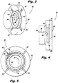
- Inlet feed passage 134 feeds into annular passage 104 tangentially, e.g., through a tangential turn section 150, shown in Figs. 3 and 4 , to induce a flow in annular passage 104 that circulated in the direction identified in Figs. 3 and 5 by the large circular arrows.
- This circulating flow generates centrifugal pressures for driving flow out of annular passage 104 through outlet passages 122.
- annular passages 104, 110, 114, and 118 are shown and described as each having four respective outlets, those skilled in the art will readily appreciate that any suitable number of outlets can be used, and that the number of outlets from one annular passage to the other need not be equal per se.
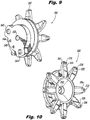
- FIG. 9-11 another embodiment of a manifold 200 is shown in which he manifold body 202 defines a central passage 252, shown in Figs. 9 and 10 therethrough configured to receive an ignitor 254 as shown in Fig. 11 .
- Manifold body 202 is similar to manifold body 102 described above, including having four inlets 242, 244, 246, and 248 (shown in Fig. 9 ) with outlet passages 222, 224, 226, and 228 (shown in Fig. 10 ), respectively, but with reduced material around the outlet passages, and where the outlet passages 222, 224, 226, and 228 turn to exit flow axially rather than radially outward.
- outlet passages in manifold 100 are fluid communication with a radially outward facing surface of the manifold 100 as shown in Fig. 1
- the outlet passages of manifold 200 are in fluid communication with an axially facing surface of the manifold 200 as shown in Fig. 10
- the inlet feed passages are in fluid communication with an axial facing surface of the fluid manifold.
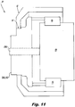
- a system 10 includes a combustor case 12 defining a manifold receptacle bore 14 therethrough.
- a manifold 200 is seated in the manifold receptacle 14 to plug seal pressure within the combustor case 12.
- the outlet passages 222, 224, 226, and 228 of manifold 200 (shown in Fig. 10 ) are connected in fluid communication with respective fluid circuits of an injector 16, shown schematically as an annular ring in Fig. 11 .
- an injector 16 shown schematically as an annular ring in Fig. 11 .
- two annular passages are configured for gaseous fuel
- two annular passages are configured for liquid fuel (e.g.
- manifold 200 and injector 16 can provide dual fuel, staged fuel injection for combustor 18.
- An ignitor 254 can be seated in central passage 252 of the manifold body 202 for ignition of fuel issued from the injector 16. If provided, the ignitor 254 should seal against the manifold 200 to prevent air from escaping the chamber. It should pass through the wall of the combustor at the tip of the ignitor 254 should be located within the combustion zone or right on the edge of the combustion zone.
- manifolds as described herein can be retrofitted into existing gas turbine engines.
- manifolds as disclosed herein can be used in any suitable application where it is desired to maintain separate fluid circuits in a manifold, such as in food or chemical processing or the like.
- a method of making a fluid manifold includes forming a manifold body, e.g., manifold body 102 or 202, with multiple, radially nested annular passages therein, e.g., annular passages 104, 110, 114, and 118, wherein each adjacent pair or the radially nested annular passages are separated by a respective wall, e.g., walls 108, 112, 116, of the manifold body.
- Forming the manifold body can include forming the manifold body including at least one wall separating radially nested passages using additive manufacturing.
- Manifolds as described herein can benefit from unitary structure, as a single body with the capability to have multiple integral manifolds therein.
- Each manifold passage can be able to divide fluid evenly among multiple individual circuits, e.g., for fuel injection.
- Manifolds as described herein can operate better at lower flow rates or power levels than traditional manifold arrangements.
- Manifolds as described herein can minimize manifold size for efficient packaging or advantageous envelope for multiple fluid circuits.
- Manifolds as described herein can fit within envelopes designed for traditional manifold arrangements, e.g., without taking up room outside a combustor case.
Landscapes
- Engineering & Computer Science (AREA)
- Chemical & Material Sciences (AREA)
- Combustion & Propulsion (AREA)
- Mechanical Engineering (AREA)
- General Engineering & Computer Science (AREA)
Abstract
Description
- The present disclosure relates to fluid manifolds, and more particularly to manifolds such as used in gas turbine engines.
- In gas turbine engines, such as industrial gas turbine engines used for power production, there is often a need to utilize more than one type of fuel. Fuel manifolds can route multiple different types of fuel to suitable injectors within the gas turbine engine. Traditional fuel manifolds are relatively complicated and bulky, especially when multiple fuels must be routed to the engine while remaining in fluid isolation from one another en route. The complicated nature of fuel manifolds is compounded if it is desired to utilize staged fuel injection, e.g., for improved turn down ratios.
- The conventional techniques have been considered satisfactory for their intended purpose. However, there is an ever present need for improved fluid manifolds. This disclosure provides a solution for this problem.
- A fluid manifold including a manifold body having a first annular passage defined between a first wall of the manifold body and a second wall of the manifold body, wherein the second wall is radially inward from the first wall. A second annular passage is nested radially inward of the firsts annular passage, wherein the second annular passage is defined between the second wall of the manifold body and a third wall of the manifold body radially inward from the second wall of the manifold body.
- A third annular passage can be nested radially inward of the second annular passage. The third annular passage is defined between the third wall of the manifold body and a fourth wall of the manifold body radially inward from the third wall of the manifold body. At least one additional annular passage can be included, wherein a first one of the at least one additional annular passage is nested radially within the third annular passage and is defined between the third wall of the manifold body and a fourth wall of the manifold body radially inward from the third wall of the manifold body. Any additional ones of the at least one additional annular passage can each be nested successively within a respective annular passage and are respectively defined between two respective walls of the manifold body.
Each of the first annular passage and the second annular passage can be defined between a respective pair of trumpet-shaped walls. Each of the first annular passage and the second annular passage can include a plurality of distinct outlet passages branching off therefrom. The outlet passages can be in fluid communication with a radially outward facing surface of the fluid manifold. It is also contemplated that the outlet passages can be in fluid communication with an axially facing surface of the fluid manifold. Each of the outlet passages can extend in a radial direction from a respective annular chamber. Each of the outlet passages can meet the respective annular chamber at a rounded corner. Each of the first annular passage and the second annular passage can include a respective inlet feed passage that feeds into a respective annular passage tangentially to induce spin on fluids flowing therethrough. The inlet feed passages can be in fluid communication with an axial facing surface of the fluid manifold. The manifold body can define a central passage therethrough configured to receive an ignitor. The manifold body including the first wall, second wall, and third wall, can be a single monolithic object. - A system includes a combustor case defining a manifold receptacle bore therethrough. A manifold including a manifold body can be seated in the manifold receptacle to plug seal pressure within the combustor case. The manifold body can include annular passages as described above. An injector can be included having first and second fuel circuits each in fluid communication with the first and second annular passages, respectively.
- The manifold can include two additional annular passages in addition to the first annular passage and the second annular passage, wherein each of the two additional annular passages is in fluid communication with a respective fuel circuit in the injector for dual fuel, dual stage fuel injection. An ignitor can be seated in a central passage of the manifold body for ignition of fuel issued from the injector.
- A method of making a fluid manifold includes forming a manifold body with multiple, radially nested annular passages therein, wherein each adjacent pair or the radially nested annular passages are separated by a respective wall of the manifold body. Forming the manifold body can include forming the manifold body including at least one wall separating radially nested passages using additive manufacturing.
- These and other features of the systems and methods of the subject disclosure will become more readily apparent to those skilled in the art from the following detailed description of the preferred embodiments taken in conjunction with the drawings.
- So that those skilled in the art to which the subject disclosure appertains will readily understand how to make and use the devices and methods of the subject disclosure without undue experimentation, preferred embodiments thereof will be described in detail herein below with reference to certain figures, wherein:
-
Fig. 1 is a perspective view of an exemplary embodiment of a manifold constructed in accordance with the present disclosure, showing the inlets and outlets for four internal annular passages; -
Fig. 2 is a cross-sectional perspective view of the manifold ofFig. 1 , showing the four internal annular passages; -
Figs. 3-5 are perspective, side elevation, and end elevation views of the manifold ofFig. 1 , schematically showing one of the annular fuel passages as a sold body for sake of clarity; -
Figs. 6-8 are inlet end perspective, side elevation, and outlet end perspective views of the manifold ofFig. 1 , showing all four annular fuel passages as solid bodies for sake of clarity; -
Fig. 9 is an inlet end perspective view of another exemplary embodiment of a manifold constructed in accordance with the present disclosure, showing the inlets; -
Fig. 10 is an outlet end perspective view of the manifold ofFig. 9 , showing the outlets; and -
Fig. 11 is a schematic cross-sectional side elevation view of the manifold ofFig. 9 , showing manifold connected in a system for distributing fuel to a fuel injector within a combustor case. - Reference will now be made to the drawings wherein like reference numerals identify similar structural features or aspects of the subject disclosure. For purposes of explanation and illustration, and not limitation, a partial view of an exemplary embodiment of a manifold in accordance with the disclosure is shown in
Fig. 1 and is designated generally byreference character 100. Other embodiments of manifolds in accordance with the disclosure, or aspects thereof, are provided inFigs. 2-11 , as will be described. The systems and methods described herein can be used to distribute and/or stage multiple fluids including liquids and gases, such as in dual stage, dual fuel injection for gas turbine engines. -
Fluid manifold 100 includes amanifold body 102 having a firstannular passage 104 defined between afirst wall 106 of themanifold body 102 and asecond wall 108 of themanifold body 102, wherein thesecond wall 108 is radially inward from thefirst wall 106. A secondannular passage 110 is nested radially inward of the firstsannular passage 104, wherein the secondannular passage 110 is defined between thesecond wall 108 of themanifold body 102 and athird wall 112 of themanifold body 102 radially inward from thesecond wall 108 of themanifold body 102. A thirdannular passage 114 is nested radially inward of the secondannular passage 110. The thirdannular passage 114 is defined between thethird wall 112 of themanifold body 102 and afourth wall 116 of themanifold body 102 radially inward from thethird wall 112 of themanifold body 102. A fourthannular passage 118 is nested radially within the thirdannular passage 114 and is defined between thefourth wall 116 of themanifold body 102 and afifth wall 120 of themanifold body 102 radially inward from thefourth wall 116 of themanifold body 102. Themanifold body 102 including the walls 106,108, 112, 116, and 120 can be a single monolithic object, e.g., formed by additive manufacturing techniques. While shown and described in exemplary embodiments with four annular passages, those skilled in the art having the benefit of this disclosure will readily appreciate that manifolds having any suitable number of nested annular passages greater than, equal to, or less than four can be made without departing from the scope of this disclosure. - Each of the walls 106,108, 112, 116, and 120 is generally trumpet-shaped, e.g. extending axially then turning radially outward. Each of the first, second, third, and fourth
annular passages distinct outlet passages outlet passages annular chamber 130. Each of theoutlet passages annular chamber 130 atrounded corners 132, as shown inFigs. 5 ,6, and 8 , for flow efficiency for fluids rounding the corner to flow outpassages annular passages inlet feed passage Figs. 6 and 7 , that feeds from arespective inlet Figs. 1 and 2 ) into a respectiveannular chamber 130 tangentially to induce spin on fluids flowing therethrough. - With reference now to
Figs. 3-4 , the firstannular passage 104 is shown with the other annular passages removed for sake of clarity in explaining the inlet feed and circulation of fluids, however, those skilled in the art will readily appreciate that the other three annular passages have similar inlet feeds and circulation.Inlet feed passage 134 feeds intoannular passage 104 tangentially, e.g., through atangential turn section 150, shown inFigs. 3 and 4 , to induce a flow inannular passage 104 that circulated in the direction identified inFigs. 3 and 5 by the large circular arrows. This circulating flow generates centrifugal pressures for driving flow out ofannular passage 104 throughoutlet passages 122. As shown inFig. 5 by the three small arrows proximate one of theoutlet passages 122, as the circulating flow approaches anoutlet passage 122, part of the flow branches into theoutlet passage 122, and part of the flow continues to circulate aroundannular passage 104 towards the next outlet passage. This flow pattern helps ensure all four of theoutlet passages 122 receive an even amount of flow, even in situations where gravity, for example, would tend to favor flow through some passages over others, e.g. gravity in some situations would increase flow in downward facing outlet passages. While all of theannular passages - Referring now to
Figs. 9-11 , another embodiment of a manifold 200 is shown in which hemanifold body 202 defines acentral passage 252, shown inFigs. 9 and 10 therethrough configured to receive anignitor 254 as shown inFig. 11 .Manifold body 202 is similar tomanifold body 102 described above, including having fourinlets Fig. 9 ) withoutlet passages Fig. 10 ), respectively, but with reduced material around the outlet passages, and where theoutlet passages manifold 100 are fluid communication with a radially outward facing surface of the manifold 100 as shown inFig. 1 , the outlet passages ofmanifold 200 are in fluid communication with an axially facing surface of the manifold 200 as shown inFig. 10 . In both manifold 100 andmanifold 200, the inlet feed passages are in fluid communication with an axial facing surface of the fluid manifold. - With reference now to
Fig. 11 , a system 10 includes acombustor case 12 defining a manifold receptacle bore 14 therethrough. A manifold 200 is seated in themanifold receptacle 14 to plug seal pressure within thecombustor case 12. Theoutlet passages Fig. 10 ) are connected in fluid communication with respective fluid circuits of aninjector 16, shown schematically as an annular ring inFig. 11 . For example, if two annular passages are configured for gaseous fuel, and if two annular passages are configured for liquid fuel (e.g. with generally smaller cross-sectional flow areas than in annular liquid passages), thenmanifold 200 andinjector 16 can provide dual fuel, staged fuel injection forcombustor 18. Those skilled in the art having the benefit of this disclosure will readily appreciate how to configure the annular passages for other single or multiple fluid, multiple-staged or single-staged configurations without departing from the scope of this disclosure. Anignitor 254 can be seated incentral passage 252 of themanifold body 202 for ignition of fuel issued from theinjector 16. If provided, theignitor 254 should seal against the manifold 200 to prevent air from escaping the chamber. It should pass through the wall of the combustor at the tip of theignitor 254 should be located within the combustion zone or right on the edge of the combustion zone. - It is contemplated that manifolds as described herein can be retrofitted into existing gas turbine engines. Moreover, while shown and described herein in the exemplary context of fuel manifolds, those skilled in the art will readily appreciate that manifolds as disclosed herein can be used in any suitable application where it is desired to maintain separate fluid circuits in a manifold, such as in food or chemical processing or the like.
- A method of making a fluid manifold, e.g.,
manifolds manifold body annular passages walls - Systems and methods as described herein allow for receiving fluids from multiple sources, and for delivering to multiple outlets for each source. It is contemplated that manifolds as described herein can benefit from unitary structure, as a single body with the capability to have multiple integral manifolds therein. Each manifold passage can be able to divide fluid evenly among multiple individual circuits, e.g., for fuel injection. Manifolds as described herein can operate better at lower flow rates or power levels than traditional manifold arrangements. Manifolds as described herein can minimize manifold size for efficient packaging or advantageous envelope for multiple fluid circuits. Manifolds as described herein can fit within envelopes designed for traditional manifold arrangements, e.g., without taking up room outside a combustor case.
- The methods and systems of the present disclosure, as described above and shown in the drawings, provide for manifolds with superior properties including compact form factor. While the apparatus and methods of the subject disclosure have been shown and described with reference to preferred embodiments, those skilled in the art will readily appreciate that changes and/or modifications may be made thereto without departing from the scope of the subject disclosure.
Claims (15)
- A fluid manifold comprising:a manifold body including a first annular passage defined between a first wall of the manifold body and a second wall of the manifold body; anda second annular passage, wherein the second annular passage is defined between the second wall of the manifold body and a third wall of the manifold body.
- The fluid manifold as recited in claim 1, further comprising a third annular passage nested radially inward of the second annular passage, wherein the third annular passage is defined between the third wall of the manifold body and a fourth wall of the manifold body radially inward from the third wall of the manifold body.
- The fluid manifold as recited in claim 2, further comprising at least one additional annular passage, wherein a first one of the at least one additional annular passage is nested radially within the third annular passage and is defined between the third wall of the manifold body and a fourth wall of the manifold body radially inward from the third wall of the manifold body, and wherein any additional ones of the at least one additional annular passage are each nested successively within a respective annular passage and are respectively defined between two respective walls of the manifold body.
- The fluid manifold as recited in claim 1, 2 or 3 wherein each of the first annular passage and the second annular passage is defined between a respective pair of trumpet-shaped walls.
- The fluid manifold as recited in any preceding claim, wherein each of the first annular passage and the second annular passage includes a plurality of distinct outlet passages branching off therefrom.
- The fluid manifold as recited in claim 5, wherein the outlet passages are in fluid communication with a radially outward facing surface of the fluid manifold, or
wherein the outlet passages are in fluid communication with an axially facing surface of the fluid manifold. - The fluid manifold as recited in claim 5 or 6, wherein each of the outlet passages extends in a radial direction from a respective annular chamber.
- The fluid manifold as recited in claim 7, wherein each of the outlet passages meets the respective annular chamber at a rounded corner.
- The fluid manifold as recited in any preceding claim, wherein each of the first annular passage and the second annular passage includes a respective inlet feed passage that feeds into a respective annular passage tangentially to induce spin on fluids flowing therethrough.
- The fluid manifold as recited in claim 9, wherein the inlet feed passages are in fluid communication with an axial facing surface of the fluid manifold.
- The fluid manifold as recited in any preceding claim, wherein the manifold body defines a central passage therethrough configured to receive an ignitor.
- The fluid manifold as recited in any preceding claim, wherein the manifold body including the first wall, second wall, and third wall, is a single monolithic object.
- A system comprising:a combustor case defining a manifold receptacle bore therethrough;a manifold including a manifold body seated in the manifold receptacle to plug seal pressure within the combustor case, wherein the manifold body including a first annular passage defined between a first wall of the manifold body and a second wall of the manifold body, wherein the second wall is radially inward from the first wall, and a second annular passage nested radially inward of the firsts annular passage, wherein the second annular passage is defined between the second wall of the manifold body and a third wall of the manifold body radially inward from the second wall of the manifold body; andan injector including first and second fuel circuits each in fluid communication with the first and second annular passages, respectively.
- The system as recited in claim 13, wherein the manifold includes two additional annular passages in addition to the first annular passage and the second annular passage, and wherein each of the two additional annular passages is in fluid communication with a respective fuel circuit in the injector for dual fuel, dual stage fuel injection, and/or
optionally, further comprising an ignitor seated in a central passage of the manifold body for ignition of fuel issued from the injector. - A method of making a fluid manifold comprising:forming a manifold body with multiple, radially nested annular passages therein, wherein each adjacent pair or the radially nested annular passages is separated by a respective wall of the manifold body,wherein, optionally, forming the manifold body includes forming the manifold body including at least one wall separating radially nested passages using additive manufacturing.
Applications Claiming Priority (1)
| Application Number | Priority Date | Filing Date | Title |
|---|---|---|---|
| US15/407,972 US10774748B2 (en) | 2017-01-17 | 2017-01-17 | Internal fuel manifolds |
Publications (2)
| Publication Number | Publication Date |
|---|---|
| EP3348813A1 true EP3348813A1 (en) | 2018-07-18 |
| EP3348813B1 EP3348813B1 (en) | 2021-10-20 |
Family
ID=61002860
Family Applications (1)
| Application Number | Title | Priority Date | Filing Date |
|---|---|---|---|
| EP18151930.7A Active EP3348813B1 (en) | 2017-01-17 | 2018-01-16 | Internal fuel manifolds and method of manufacturing |
Country Status (2)
| Country | Link |
|---|---|
| US (1) | US10774748B2 (en) |
| EP (1) | EP3348813B1 (en) |
Cited By (1)
| Publication number | Priority date | Publication date | Assignee | Title |
|---|---|---|---|---|
| EP3460217A1 (en) * | 2017-09-25 | 2019-03-27 | Delavan, Inc. | Multiple circuit manifolds |
Citations (4)
| Publication number | Priority date | Publication date | Assignee | Title |
|---|---|---|---|---|
| US4854127A (en) * | 1988-01-14 | 1989-08-08 | General Electric Company | Bimodal swirler injector for a gas turbine combustor |
| WO2010024989A2 (en) * | 2008-08-28 | 2010-03-04 | Woodward Governor Company | Multi passage fuel manifold and methods of construction |
| EP2629016A2 (en) * | 2012-02-16 | 2013-08-21 | Delavan Inc. | Variable angle multi-point injection |
| WO2016028974A1 (en) * | 2014-08-21 | 2016-02-25 | Williams International Co., L.L.C. | Valvular-conduit manifold |
Family Cites Families (4)
| Publication number | Priority date | Publication date | Assignee | Title |
|---|---|---|---|---|
| US5361586A (en) * | 1993-04-15 | 1994-11-08 | Westinghouse Electric Corporation | Gas turbine ultra low NOx combustor |
| US6289676B1 (en) * | 1998-06-26 | 2001-09-18 | Pratt & Whitney Canada Corp. | Simplex and duplex injector having primary and secondary annular lud channels and primary and secondary lud nozzles |
| EP2107310A1 (en) * | 2008-04-01 | 2009-10-07 | Siemens Aktiengesellschaft | Burner |
| US20090255256A1 (en) * | 2008-04-11 | 2009-10-15 | General Electric Company | Method of manufacturing combustor components |
-
2017
- 2017-01-17 US US15/407,972 patent/US10774748B2/en active Active
-
2018
- 2018-01-16 EP EP18151930.7A patent/EP3348813B1/en active Active
Patent Citations (4)
| Publication number | Priority date | Publication date | Assignee | Title |
|---|---|---|---|---|
| US4854127A (en) * | 1988-01-14 | 1989-08-08 | General Electric Company | Bimodal swirler injector for a gas turbine combustor |
| WO2010024989A2 (en) * | 2008-08-28 | 2010-03-04 | Woodward Governor Company | Multi passage fuel manifold and methods of construction |
| EP2629016A2 (en) * | 2012-02-16 | 2013-08-21 | Delavan Inc. | Variable angle multi-point injection |
| WO2016028974A1 (en) * | 2014-08-21 | 2016-02-25 | Williams International Co., L.L.C. | Valvular-conduit manifold |
Cited By (2)
| Publication number | Priority date | Publication date | Assignee | Title |
|---|---|---|---|---|
| EP3460217A1 (en) * | 2017-09-25 | 2019-03-27 | Delavan, Inc. | Multiple circuit manifolds |
| US10570826B2 (en) | 2017-09-25 | 2020-02-25 | Delavan Inc. | Fuel manifold with nested annular passages and radially extending channels |
Also Published As
| Publication number | Publication date |
|---|---|
| US20180202364A1 (en) | 2018-07-19 |
| US10774748B2 (en) | 2020-09-15 |
| EP3348813B1 (en) | 2021-10-20 |
Similar Documents
| Publication | Publication Date | Title |
|---|---|---|
| US20220333777A1 (en) | Fuel injection for integral combustor and turbine vane | |
| US10364751B2 (en) | Fuel staging | |
| US10344981B2 (en) | Staged dual fuel radial nozzle with radial liquid fuel distributor | |
| EP3336434B1 (en) | Dual fuel radial flow nozzle for a gas turbine | |
| EP3156732A1 (en) | Airblast injectors | |
| US10041741B2 (en) | Heat exchanger for gas turbine engines | |
| CN106795816B (en) | Dual fuel-fuel injector | |
| RU2011134663A (en) | TURBOCHARGE COMBUSTION CHAMBER WALL WITH SINGLE RING ROW ROW OF OPENINGS FOR INPUT OF PRIMARY AND MIXING AIR | |
| EP3336432B1 (en) | Staged radial air swirler with radial liquid fuel distributor | |
| US20250277458A1 (en) | Static de-aerator and lubricant system | |
| EP3348813B1 (en) | Internal fuel manifolds and method of manufacturing | |
| CA2580594C (en) | Fuel manifold with reduced losses | |
| EP3182014A1 (en) | Injector fittings | |
| US20210207539A1 (en) | Internal manifold for multipoint injection | |
| US10240793B2 (en) | Single-fitting, dual-circuit fuel nozzle | |
| US9410416B2 (en) | Subsea flow splitting arrangement | |
| US10570826B2 (en) | Fuel manifold with nested annular passages and radially extending channels | |
| CN222256551U (en) | Distributor assembly and burner | |
| CN205825022U (en) | Neat gas burner | |
| US11686216B2 (en) | Turbomachine output bearing support | |
| KR102547191B1 (en) | An oil separator including multi storage tanks which are overlapped | |
| WO2016001301A1 (en) | Fuel distribution device, gas turbine engine and mounting method | |
| US11892166B2 (en) | Fuel injector with a purge circuit for an aircraft turbine engine | |
| US10557630B1 (en) | Stackable air swirlers | |
| CN117646894A (en) | Base assembly and burner |
Legal Events
| Date | Code | Title | Description |
|---|---|---|---|
| PUAI | Public reference made under article 153(3) epc to a published international application that has entered the european phase |
Free format text: ORIGINAL CODE: 0009012 |
|
| STAA | Information on the status of an ep patent application or granted ep patent |
Free format text: STATUS: THE APPLICATION HAS BEEN PUBLISHED |
|
| AK | Designated contracting states |
Kind code of ref document: A1 Designated state(s): AL AT BE BG CH CY CZ DE DK EE ES FI FR GB GR HR HU IE IS IT LI LT LU LV MC MK MT NL NO PL PT RO RS SE SI SK SM TR |
|
| AX | Request for extension of the european patent |
Extension state: BA ME |
|
| STAA | Information on the status of an ep patent application or granted ep patent |
Free format text: STATUS: REQUEST FOR EXAMINATION WAS MADE |
|
| 17P | Request for examination filed |
Effective date: 20190117 |
|
| RBV | Designated contracting states (corrected) |
Designated state(s): AL AT BE BG CH CY CZ DE DK EE ES FI FR GB GR HR HU IE IS IT LI LT LU LV MC MK MT NL NO PL PT RO RS SE SI SK SM TR |
|
| GRAP | Despatch of communication of intention to grant a patent |
Free format text: ORIGINAL CODE: EPIDOSNIGR1 |
|
| STAA | Information on the status of an ep patent application or granted ep patent |
Free format text: STATUS: GRANT OF PATENT IS INTENDED |
|
| INTG | Intention to grant announced |
Effective date: 20210430 |
|
| GRAS | Grant fee paid |
Free format text: ORIGINAL CODE: EPIDOSNIGR3 |
|
| GRAA | (expected) grant |
Free format text: ORIGINAL CODE: 0009210 |
|
| STAA | Information on the status of an ep patent application or granted ep patent |
Free format text: STATUS: THE PATENT HAS BEEN GRANTED |
|
| AK | Designated contracting states |
Kind code of ref document: B1 Designated state(s): AL AT BE BG CH CY CZ DE DK EE ES FI FR GB GR HR HU IE IS IT LI LT LU LV MC MK MT NL NO PL PT RO RS SE SI SK SM TR |
|
| REG | Reference to a national code |
Ref country code: GB Ref legal event code: FG4D |
|
| REG | Reference to a national code |
Ref country code: CH Ref legal event code: EP |
|
| REG | Reference to a national code |
Ref country code: DE Ref legal event code: R096 Ref document number: 602018025172 Country of ref document: DE |
|
| REG | Reference to a national code |
Ref country code: IE Ref legal event code: FG4D |
|
| REG | Reference to a national code |
Ref country code: AT Ref legal event code: REF Ref document number: 1440136 Country of ref document: AT Kind code of ref document: T Effective date: 20211115 |
|
| REG | Reference to a national code |
Ref country code: LT Ref legal event code: MG9D |
|
| REG | Reference to a national code |
Ref country code: NL Ref legal event code: MP Effective date: 20211020 |
|
| REG | Reference to a national code |
Ref country code: AT Ref legal event code: MK05 Ref document number: 1440136 Country of ref document: AT Kind code of ref document: T Effective date: 20211020 |
|
| PG25 | Lapsed in a contracting state [announced via postgrant information from national office to epo] |
Ref country code: RS Free format text: LAPSE BECAUSE OF FAILURE TO SUBMIT A TRANSLATION OF THE DESCRIPTION OR TO PAY THE FEE WITHIN THE PRESCRIBED TIME-LIMIT Effective date: 20211020 Ref country code: LT Free format text: LAPSE BECAUSE OF FAILURE TO SUBMIT A TRANSLATION OF THE DESCRIPTION OR TO PAY THE FEE WITHIN THE PRESCRIBED TIME-LIMIT Effective date: 20211020 Ref country code: FI Free format text: LAPSE BECAUSE OF FAILURE TO SUBMIT A TRANSLATION OF THE DESCRIPTION OR TO PAY THE FEE WITHIN THE PRESCRIBED TIME-LIMIT Effective date: 20211020 Ref country code: BG Free format text: LAPSE BECAUSE OF FAILURE TO SUBMIT A TRANSLATION OF THE DESCRIPTION OR TO PAY THE FEE WITHIN THE PRESCRIBED TIME-LIMIT Effective date: 20220120 Ref country code: AT Free format text: LAPSE BECAUSE OF FAILURE TO SUBMIT A TRANSLATION OF THE DESCRIPTION OR TO PAY THE FEE WITHIN THE PRESCRIBED TIME-LIMIT Effective date: 20211020 |
|
| RAP4 | Party data changed (patent owner data changed or rights of a patent transferred) |
Owner name: COLLINS ENGINE NOZZLES, INC. |
|
| PG25 | Lapsed in a contracting state [announced via postgrant information from national office to epo] |
Ref country code: IS Free format text: LAPSE BECAUSE OF FAILURE TO SUBMIT A TRANSLATION OF THE DESCRIPTION OR TO PAY THE FEE WITHIN THE PRESCRIBED TIME-LIMIT Effective date: 20220220 Ref country code: SE Free format text: LAPSE BECAUSE OF FAILURE TO SUBMIT A TRANSLATION OF THE DESCRIPTION OR TO PAY THE FEE WITHIN THE PRESCRIBED TIME-LIMIT Effective date: 20211020 Ref country code: PT Free format text: LAPSE BECAUSE OF FAILURE TO SUBMIT A TRANSLATION OF THE DESCRIPTION OR TO PAY THE FEE WITHIN THE PRESCRIBED TIME-LIMIT Effective date: 20220221 Ref country code: PL Free format text: LAPSE BECAUSE OF FAILURE TO SUBMIT A TRANSLATION OF THE DESCRIPTION OR TO PAY THE FEE WITHIN THE PRESCRIBED TIME-LIMIT Effective date: 20211020 Ref country code: NO Free format text: LAPSE BECAUSE OF FAILURE TO SUBMIT A TRANSLATION OF THE DESCRIPTION OR TO PAY THE FEE WITHIN THE PRESCRIBED TIME-LIMIT Effective date: 20220120 Ref country code: NL Free format text: LAPSE BECAUSE OF FAILURE TO SUBMIT A TRANSLATION OF THE DESCRIPTION OR TO PAY THE FEE WITHIN THE PRESCRIBED TIME-LIMIT Effective date: 20211020 Ref country code: LV Free format text: LAPSE BECAUSE OF FAILURE TO SUBMIT A TRANSLATION OF THE DESCRIPTION OR TO PAY THE FEE WITHIN THE PRESCRIBED TIME-LIMIT Effective date: 20211020 Ref country code: HR Free format text: LAPSE BECAUSE OF FAILURE TO SUBMIT A TRANSLATION OF THE DESCRIPTION OR TO PAY THE FEE WITHIN THE PRESCRIBED TIME-LIMIT Effective date: 20211020 Ref country code: GR Free format text: LAPSE BECAUSE OF FAILURE TO SUBMIT A TRANSLATION OF THE DESCRIPTION OR TO PAY THE FEE WITHIN THE PRESCRIBED TIME-LIMIT Effective date: 20220121 Ref country code: ES Free format text: LAPSE BECAUSE OF FAILURE TO SUBMIT A TRANSLATION OF THE DESCRIPTION OR TO PAY THE FEE WITHIN THE PRESCRIBED TIME-LIMIT Effective date: 20211020 |
|
| REG | Reference to a national code |
Ref country code: DE Ref legal event code: R097 Ref document number: 602018025172 Country of ref document: DE |
|
| PG25 | Lapsed in a contracting state [announced via postgrant information from national office to epo] |
Ref country code: SM Free format text: LAPSE BECAUSE OF FAILURE TO SUBMIT A TRANSLATION OF THE DESCRIPTION OR TO PAY THE FEE WITHIN THE PRESCRIBED TIME-LIMIT Effective date: 20211020 Ref country code: SK Free format text: LAPSE BECAUSE OF FAILURE TO SUBMIT A TRANSLATION OF THE DESCRIPTION OR TO PAY THE FEE WITHIN THE PRESCRIBED TIME-LIMIT Effective date: 20211020 Ref country code: RO Free format text: LAPSE BECAUSE OF FAILURE TO SUBMIT A TRANSLATION OF THE DESCRIPTION OR TO PAY THE FEE WITHIN THE PRESCRIBED TIME-LIMIT Effective date: 20211020 Ref country code: EE Free format text: LAPSE BECAUSE OF FAILURE TO SUBMIT A TRANSLATION OF THE DESCRIPTION OR TO PAY THE FEE WITHIN THE PRESCRIBED TIME-LIMIT Effective date: 20211020 Ref country code: DK Free format text: LAPSE BECAUSE OF FAILURE TO SUBMIT A TRANSLATION OF THE DESCRIPTION OR TO PAY THE FEE WITHIN THE PRESCRIBED TIME-LIMIT Effective date: 20211020 Ref country code: CZ Free format text: LAPSE BECAUSE OF FAILURE TO SUBMIT A TRANSLATION OF THE DESCRIPTION OR TO PAY THE FEE WITHIN THE PRESCRIBED TIME-LIMIT Effective date: 20211020 |
|
| PLBE | No opposition filed within time limit |
Free format text: ORIGINAL CODE: 0009261 |
|
| STAA | Information on the status of an ep patent application or granted ep patent |
Free format text: STATUS: NO OPPOSITION FILED WITHIN TIME LIMIT |
|
| PG25 | Lapsed in a contracting state [announced via postgrant information from national office to epo] |
Ref country code: MC Free format text: LAPSE BECAUSE OF FAILURE TO SUBMIT A TRANSLATION OF THE DESCRIPTION OR TO PAY THE FEE WITHIN THE PRESCRIBED TIME-LIMIT Effective date: 20211020 |
|
| REG | Reference to a national code |
Ref country code: CH Ref legal event code: PL |
|
| 26N | No opposition filed |
Effective date: 20220721 |
|
| REG | Reference to a national code |
Ref country code: BE Ref legal event code: MM Effective date: 20220131 |
|
| PG25 | Lapsed in a contracting state [announced via postgrant information from national office to epo] |
Ref country code: LU Free format text: LAPSE BECAUSE OF NON-PAYMENT OF DUE FEES Effective date: 20220116 Ref country code: AL Free format text: LAPSE BECAUSE OF FAILURE TO SUBMIT A TRANSLATION OF THE DESCRIPTION OR TO PAY THE FEE WITHIN THE PRESCRIBED TIME-LIMIT Effective date: 20211020 |
|
| PG25 | Lapsed in a contracting state [announced via postgrant information from national office to epo] |
Ref country code: SI Free format text: LAPSE BECAUSE OF FAILURE TO SUBMIT A TRANSLATION OF THE DESCRIPTION OR TO PAY THE FEE WITHIN THE PRESCRIBED TIME-LIMIT Effective date: 20211020 Ref country code: BE Free format text: LAPSE BECAUSE OF NON-PAYMENT OF DUE FEES Effective date: 20220131 |
|
| PG25 | Lapsed in a contracting state [announced via postgrant information from national office to epo] |
Ref country code: LI Free format text: LAPSE BECAUSE OF NON-PAYMENT OF DUE FEES Effective date: 20220131 Ref country code: CH Free format text: LAPSE BECAUSE OF NON-PAYMENT OF DUE FEES Effective date: 20220131 |
|
| PG25 | Lapsed in a contracting state [announced via postgrant information from national office to epo] |
Ref country code: IE Free format text: LAPSE BECAUSE OF NON-PAYMENT OF DUE FEES Effective date: 20220116 |
|
| PG25 | Lapsed in a contracting state [announced via postgrant information from national office to epo] |
Ref country code: IT Free format text: LAPSE BECAUSE OF FAILURE TO SUBMIT A TRANSLATION OF THE DESCRIPTION OR TO PAY THE FEE WITHIN THE PRESCRIBED TIME-LIMIT Effective date: 20211020 |
|
| P01 | Opt-out of the competence of the unified patent court (upc) registered |
Effective date: 20230530 |
|
| PG25 | Lapsed in a contracting state [announced via postgrant information from national office to epo] |
Ref country code: HU Free format text: LAPSE BECAUSE OF FAILURE TO SUBMIT A TRANSLATION OF THE DESCRIPTION OR TO PAY THE FEE WITHIN THE PRESCRIBED TIME-LIMIT; INVALID AB INITIO Effective date: 20180116 |
|
| PG25 | Lapsed in a contracting state [announced via postgrant information from national office to epo] |
Ref country code: MK Free format text: LAPSE BECAUSE OF FAILURE TO SUBMIT A TRANSLATION OF THE DESCRIPTION OR TO PAY THE FEE WITHIN THE PRESCRIBED TIME-LIMIT Effective date: 20211020 Ref country code: CY Free format text: LAPSE BECAUSE OF FAILURE TO SUBMIT A TRANSLATION OF THE DESCRIPTION OR TO PAY THE FEE WITHIN THE PRESCRIBED TIME-LIMIT Effective date: 20211020 |
|
| PG25 | Lapsed in a contracting state [announced via postgrant information from national office to epo] |
Ref country code: TR Free format text: LAPSE BECAUSE OF FAILURE TO SUBMIT A TRANSLATION OF THE DESCRIPTION OR TO PAY THE FEE WITHIN THE PRESCRIBED TIME-LIMIT Effective date: 20211020 |
|
| PG25 | Lapsed in a contracting state [announced via postgrant information from national office to epo] |
Ref country code: MT Free format text: LAPSE BECAUSE OF FAILURE TO SUBMIT A TRANSLATION OF THE DESCRIPTION OR TO PAY THE FEE WITHIN THE PRESCRIBED TIME-LIMIT Effective date: 20211020 |
|
| PGFP | Annual fee paid to national office [announced via postgrant information from national office to epo] |
Ref country code: GB Payment date: 20251220 Year of fee payment: 9 |
|
| PGFP | Annual fee paid to national office [announced via postgrant information from national office to epo] |
Ref country code: FR Payment date: 20251217 Year of fee payment: 9 |
|
| PGFP | Annual fee paid to national office [announced via postgrant information from national office to epo] |
Ref country code: DE Payment date: 20251217 Year of fee payment: 9 |