EP3348811B1 - Turbineneinlauf und verfahren zur verminderung eines ungleichförmigen eingangsluftstroms zu einer turbomaschine - Google Patents
Turbineneinlauf und verfahren zur verminderung eines ungleichförmigen eingangsluftstroms zu einer turbomaschine Download PDFInfo
- Publication number
- EP3348811B1 EP3348811B1 EP17199340.5A EP17199340A EP3348811B1 EP 3348811 B1 EP3348811 B1 EP 3348811B1 EP 17199340 A EP17199340 A EP 17199340A EP 3348811 B1 EP3348811 B1 EP 3348811B1
- Authority
- EP
- European Patent Office
- Prior art keywords
- vanes
- airflow
- correction
- air flow
- inlet
- Prior art date
- Legal status (The legal status is an assumption and is not a legal conclusion. Google has not performed a legal analysis and makes no representation as to the accuracy of the status listed.)
- Active
Links
Images


Classifications
-
- F—MECHANICAL ENGINEERING; LIGHTING; HEATING; WEAPONS; BLASTING
- F02—COMBUSTION ENGINES; HOT-GAS OR COMBUSTION-PRODUCT ENGINE PLANTS
- F02C—GAS-TURBINE PLANTS; AIR INTAKES FOR JET-PROPULSION PLANTS; CONTROLLING FUEL SUPPLY IN AIR-BREATHING JET-PROPULSION PLANTS
- F02C7/00—Features, components parts, details or accessories, not provided for in, or of interest apart form groups F02C1/00 - F02C6/00; Air intakes for jet-propulsion plants
- F02C7/04—Air intakes for gas-turbine plants or jet-propulsion plants
- F02C7/057—Control or regulation
-
- F—MECHANICAL ENGINEERING; LIGHTING; HEATING; WEAPONS; BLASTING
- F02—COMBUSTION ENGINES; HOT-GAS OR COMBUSTION-PRODUCT ENGINE PLANTS
- F02C—GAS-TURBINE PLANTS; AIR INTAKES FOR JET-PROPULSION PLANTS; CONTROLLING FUEL SUPPLY IN AIR-BREATHING JET-PROPULSION PLANTS
- F02C7/00—Features, components parts, details or accessories, not provided for in, or of interest apart form groups F02C1/00 - F02C6/00; Air intakes for jet-propulsion plants
- F02C7/04—Air intakes for gas-turbine plants or jet-propulsion plants
- F02C7/042—Air intakes for gas-turbine plants or jet-propulsion plants having variable geometry
-
- F—MECHANICAL ENGINEERING; LIGHTING; HEATING; WEAPONS; BLASTING
- F02—COMBUSTION ENGINES; HOT-GAS OR COMBUSTION-PRODUCT ENGINE PLANTS
- F02C—GAS-TURBINE PLANTS; AIR INTAKES FOR JET-PROPULSION PLANTS; CONTROLLING FUEL SUPPLY IN AIR-BREATHING JET-PROPULSION PLANTS
- F02C7/00—Features, components parts, details or accessories, not provided for in, or of interest apart form groups F02C1/00 - F02C6/00; Air intakes for jet-propulsion plants
- F02C7/04—Air intakes for gas-turbine plants or jet-propulsion plants
- F02C7/05—Air intakes for gas-turbine plants or jet-propulsion plants having provisions for obviating the penetration of damaging objects or particles
- F02C7/055—Air intakes for gas-turbine plants or jet-propulsion plants having provisions for obviating the penetration of damaging objects or particles with intake grids, screens or guards
-
- F—MECHANICAL ENGINEERING; LIGHTING; HEATING; WEAPONS; BLASTING
- F02—COMBUSTION ENGINES; HOT-GAS OR COMBUSTION-PRODUCT ENGINE PLANTS
- F02K—JET-PROPULSION PLANTS
- F02K3/00—Plants including a gas turbine driving a compressor or a ducted fan
-
- F—MECHANICAL ENGINEERING; LIGHTING; HEATING; WEAPONS; BLASTING
- F02—COMBUSTION ENGINES; HOT-GAS OR COMBUSTION-PRODUCT ENGINE PLANTS
- F02C—GAS-TURBINE PLANTS; AIR INTAKES FOR JET-PROPULSION PLANTS; CONTROLLING FUEL SUPPLY IN AIR-BREATHING JET-PROPULSION PLANTS
- F02C7/00—Features, components parts, details or accessories, not provided for in, or of interest apart form groups F02C1/00 - F02C6/00; Air intakes for jet-propulsion plants
- F02C7/04—Air intakes for gas-turbine plants or jet-propulsion plants
-
- F—MECHANICAL ENGINEERING; LIGHTING; HEATING; WEAPONS; BLASTING
- F05—INDEXING SCHEMES RELATING TO ENGINES OR PUMPS IN VARIOUS SUBCLASSES OF CLASSES F01-F04
- F05D—INDEXING SCHEME FOR ASPECTS RELATING TO NON-POSITIVE-DISPLACEMENT MACHINES OR ENGINES, GAS-TURBINES OR JET-PROPULSION PLANTS
- F05D2300/00—Materials; Properties thereof
- F05D2300/50—Intrinsic material properties or characteristics
- F05D2300/505—Shape memory behaviour
-
- Y—GENERAL TAGGING OF NEW TECHNOLOGICAL DEVELOPMENTS; GENERAL TAGGING OF CROSS-SECTIONAL TECHNOLOGIES SPANNING OVER SEVERAL SECTIONS OF THE IPC; TECHNICAL SUBJECTS COVERED BY FORMER USPC CROSS-REFERENCE ART COLLECTIONS [XRACs] AND DIGESTS
- Y02—TECHNOLOGIES OR APPLICATIONS FOR MITIGATION OR ADAPTATION AGAINST CLIMATE CHANGE
- Y02T—CLIMATE CHANGE MITIGATION TECHNOLOGIES RELATED TO TRANSPORTATION
- Y02T50/00—Aeronautics or air transport
- Y02T50/60—Efficient propulsion technologies, e.g. for aircraft
Definitions
- the disclosed subject matter relates generally to turbomachines, and more specifically to an airflow control device for reducing airflow distortions at the inlet of a turbomachine.
- Turbomachines convert chemical energy into rotational energy that can be used in a wide range of applications.
- a gas turbine is one of many different types of turbomachines.
- a gas turbine comprises a rotatable shaft and a plurality of blades. In some applications at least some of the plurality of blades may comprise a fan.
- Some examples of types of gas turbines include turbofan, turbojet, turboshaft and turboprop engines.
- Other types of turbomachines include, inter alia, water turbines, steam turbines and wind turbines.
- turbomachines are used to provide propulsion to some aircraft.
- a typical turbine engine comprises an inlet, a compressor (which may include a high and low pressure compressor), a combustor, a turbine (which may comprise a high-pressure turbine and a low-pressure turbine), and an outlet.
- Airflow distortions - which lead to the creation of non-uniformity of airflow - may be caused by, for example, the air passing through an inlet duct prior to entering the inlet of the turbomachine, movement of the turbomachine relative to a column of air, the presence of objects such as, e.g., a runway near to an airframe carrying the turbomachine, the airframe itself, an engine casing or housing, or a combination of these items.
- Non-uniform airflow may lack uniformity in the radial, circumferential, axial, or any combination of these directional pressure and velocity fields in the turbomachine. In turn, the non-uniform pressure and velocity fields may reduce the efficiency of the turbomachine.
- the flow conditions encountered by a blade would not change with engine operation, along the circumference through which the blade travels, or both.
- designers, knowing that these conditions will change will design a blade for a range of flow conditions under which the turbomachine must operate.
- the particular flow conditions encountered by the blade at one location may differ from the flow conditions at another location located along the circumference through which the blade travels. Both of these conditions may vary from the ideal conditions for which the blade was optimally designed. Flow distortions are typically detrimental to turbomachine performance and are thus advantageously avoided.
- United States patent application US 2016/069275 A1 describes a turbomachine comprising a plurality of variable pitch radial stator vanes with means for individually regulating the pitch of the variable-pitch radial vanes if heterogeneity of the air flow in the secondary duct is detected.
- United States patent application US 2009/297334 A1 describes an inlet guide vane assembly that includes an active control feedback system and a plurality of inlet guide vanes.
- the inlet guide vanes are variable between a plurality of positions.
- Each of the plurality of inlet guide vanes is positioned in response to an output of the activate control feedback system.
- European patent application EP 3205833 A1 describes a gas turbine engine having instrumented airflow path components and a method of determining and adjusting a distortion condition by controlling one or more sectors of variable guide vanes.
- United States patent application US 2016/102611 A1 describes an environmental defense shield including symmetric airfoil-shaped vanes contributing to and positioned around a plenum space and positioned in front of a turbine engine.
- the environmental defense shield serves to protect the engine from debris while also smoothing airflow into the engine.
- the disclosure provides a method of adaptively removing airflow distortions in a turbine engine, and a turbine inlet duct, as set out in the appended claims.
- the disclosed subject matter provides a method of adaptively removing airflow distortions in a turbine engine having an air inlet duct prior to the compressor stage, the distortions being caused at least in part by the interaction of air flow with the air inlet duct, the method comprising the steps of: determining the distortion in the airflow; positioning a plurality of correction vanes based at least upon the determined distortion; wherein each of the plurality of correction vanes is oriented to a respective angle of incidence when at a temperature approximately equal the respective local temperature; and exposing the airflow to the plurality of correction vanes.
- a method of adaptively removing the distortions prior to the compressor stage comprising the steps of: determining the distortion in the airflow; positioning a plurality of correction vanes based at least upon the determined distortion; and exposing the airflow to the plurality of correction vanes.
- the turbine engine may have an air inlet duct prior to the compressor stage. Airflow distortions are caused at least in part by the interaction of the air flow with the air inlet duct.
- the steps of the method may comprise determining the distortion in the airflow, positioning a plurality of correction vanes based at least upon the determined distortion, and exposing the airflow to the plurality of correction vanes.
- the plurality of correction vanes may be provided of shape memory materials.
- the step of positioning the plurality of correction vanes may comprise applying an electrical current to at least one respective correction vane of the plurality of correction vanes. The application of electrical current transitions the respective correction vane from a first state to a second state.
- the step of positioning the plurality of correction vanes may comprises heating the vanes by aerothermal heating.
- the step of determining the distortion may comprise predetermining the distortion as a function of Mach number.
- the step of determining the distortion may comprise associating a plurality of local temperatures as a function of Mach number.
- the step of determining the distortion may comprise determining a desired angle of incidence for each of the plurality of correction vanes.
- the step of determining the distortion may comprise sensing the airflow characteristics in the air inlet duct.
- the step of determining the distortion may comprise determining current operational parameters.
- the operational parameters may be selected from the group consisting of angle of attack, turning, climb, roll, yaw, pitch, thrust, altitude, attitude and velocity, or they may be selected from the group consisting of takeoff, landing, cruise, loiter, supersonic flight, and subsonic flight.
- the positioning may be performed in real time.
- the plurality of vanes may be positioned at two longitudinal displaced stations within the air inlet duct.
- the disclosed subject matter provides a turbine inlet duct comprising: an air passage defined by the inlet duct, the air passage having a center path defining the airflow through the inlet duct, wherein the center path comprises at least one curve; and a conditioning grid with a plurality of vanes located within the passage, the plurality of vanes comprising a plurality shape memory blades, wherein the at least one curve is positioned up stream of the conditioning grid, and wherein each of the plurality of vanes are configured to alter the air flow downstream of the at least one curve.
- the inlet duct may comprise an air passage and a conditioning grid.
- the air passage may be defined by the inlet duct of the turbine and may have a center path defining the airflow through the inlet duct.
- the center path comprises at least one curve.
- the conditioning grid may have a plurality of vanes located with the passage.
- the at least one curve is positioned upstream of the conditioning grid.
- Each of the plurality of vanes are configured to alter the air flow downstream of the at least one curve.
- Each of the plurality of vanes may be oriented to a respective desired angle of incidence in a first state and oriented to a respective second desired angle of incidence in a second state.
- the application of an electrical current to a respective one of the plurality of vanes may transition the respective one of the plurality of correction vanes from a first state to a second state.
- the plurality of vanes in the correction grid may form a shape selected from the group consisting of a rectangular grid, concentric circles, spokes, or combinations thereof.
- an inlet conditioner system comprising: a serpentine inlet defining an air passage; an adaptable conditioning grid located within the air passage and operable upon an airflow within the air passage; a sensor suite located within the serpentine inlet configured to sense a characteristic of the airflow within the serpentine inlet; a control system operably connected to the sensor suite and the adaptable conditioning grid, said control system adapted to configure the adaptable conditioning grid based on the sensed characteristic.
- the inlet conditioner system may comprise a serpentine inlet defining an air passage, an adaptable conditioning grid, a sensor suite and a control system.
- the adaptable conditioning grid may be located with the air passage and may be operable upon an airflow within the air passage.
- the sensor suite may be located within the serpentine inlet and may be configured to sense a characteristic of the airflow within the serpentine inlet.
- the sensor suite may comprise a plurality of sensors located upstream of the adaptable conditioning grid and a second plurality of sensors located downstream of the adaptable conditioning grid.
- the control system may be operably connected to the sensor suite and the adaptable conditioning grid and may be adapted to configure the adaptable conditioning grid based on the sensed characteristic.
- a turbomachine is understood to reference any machine using a turbine including gas turbine engines, wind turbines, steam turbines, water turbines, and the like.
- a turbomachine comprises at least a rotatable shaft and a plurality of blades.
- the disclosed subject matter is directed to a control device for controlling the airflow at the inlet of a turbomachine, such as, e.g., a compressor of a turbine engine, and other applications in a turbomachine which are susceptible to detrimental flow distortions.
- a turbomachine such as, e.g., a compressor of a turbine engine
- the disclosed subject matter may control the mixing of one or more internal airflows (e.g., the fan bypass flow and engine core flow), or control an airflow before or after it is divided (e.g., the diving of the fan air flow into a bypass flow and core flow), as a well as airflow(s) exiting or mixing at the exit to the turbomachinery.
- the disclosed subject matter may be applicable to correcting any airflow within a turbomachine.
- Various components of a turbine engine - such as the vanes and blades of a compressor - are designed based on anticipated velocity vectors and airflow pressures that may encompass a range of values.
- a rotating blade of a fan or compressor is designed based on a particular set of inlet air velocity vectors and pressures; the compressor and turbine blades and other components of a turbomachine are designed to function with the resultant internal airflows which occur over the range of the design inlet air velocity vectors and pressures.
- FIG. 1A is a schematic diagram of a turbine engine 100 encountering a uniformly distributed inlet airflow 101.
- Engine 100 comprises an inlet fan 102, compressor 104, combustor 106, turbine 108, and nozzle 110 disposed about a common axis of rotation A. These components are disposed within an engine casing 112. Some portion of the volume inside the casing 112 may be a bypass flow path 114 which allows some portion of the air passing through the inlet fan 102 to bypass the compressor 104, combustor 106, turbine 108, and nozzle 110.
- a nose cone 116 is coupled to the engine 100 axially forward of the inlet fan 102.
- the uniformly distributed air flow 101 of Figure 1A represents the ideal case for a turbine engine 100.
- the air flow 101 enters the turbine engine 100 at inlet fan 102 having a uniform air speed and direction.
- direction of air flow entering the engine 100 be circumferentially uniform about and along the axis of rotation A and/or normal to a plane P defined by the inlet fan 102 wherein plane P is normal to the axis of rotation A.
- Figure 1B presents a schematic diagram of an angled uniformly distributed air flow 118 entering turbine engine 100.
- An angled air distribution has an air direction which is non parallel to an axis of rotation A of the turbine engine 100 and/or normal to a plane P defined by the inlet fan 102 which is normal to the axis of rotation A.
- An angled uniform airflow 118 may be created, for example, in aviation applications where there is relative movement between the turbine engine 100 and the atmosphere.
- Figure 2 presents a schematic diagram of a non-uniformly distributed air flow 201.
- a non-uniform air flow 201 may comprise a plurality of air velocity vectors and pressures (not shown. A few of the plurality of air flow vectors are illustrated in Figure 2 .
- a turbine engine 100 may be disposed downstream of an inlet duct 202, which is coupled to casing 112.
- Inlet duct 202 is configured to direct air flow to the inlet fan 102 or compressor 104 of the turbine engine 100. Interaction of the air flow with the inlet duct 202 may result in the development of a non-uniform air flow distribution 201 in which the direction and/or magnitude of the velocity vectors are not uniform..
- a non-uniform air flow may also be created by the interaction of the airframe or turbine engine casing or housing (particularly the inlet) and the atmosphere (or other fluid), movement of a machine to which the engine is attached, such as, e.g., an airframe, hull, or chassis, relative to the atmosphere, or a combination of these factors.
- FIG. 3 is a schematic axial view of the air flow vectors 302 in a portion of inlet duct 202. It should be noted, although not represented in Fig. 3 , the flow vectors 302 typically have an axial velocity component. As shown in Figure 3 , complex air flow patterns can develop as air flow interacts with ducting and/or objects in the flow path such as struts. These air flow patterns may include a pair of counter-rotational swirl zones 304 as shown. During aircraft maneuvers, when air enters the duct 202 at vectors oblique to the turbine these air flow patterns may be further complicated. The development of any air flow pattern outside of predicable and uniformly distributed air flow can degrade engine performance.
- the non-uniform airflow may result in distortions that are not symmetrical. While the distortions in Figure 3 show some symmetry about a line half way between the furthest left and furthest right portions of the inlet duct 202, such a symmetry may not always occur with every possible distortion of the airflow. Further complicating engine design, the distortions shown in FIG. 3 can change during operation of the engine.
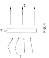
- Figure 4 is a schematic diagram showing the correction of a non-uniformly-distributed air flow 401 by an air flow controller 402. Air flow 401 incident upon the controller 402 at an angle passes through the controller 402 and exits as uniformly-distributed air flow 404.
- FIG. 5 is a perspective view of a controller 402 in accordance with some embodiments of the disclosed subject matter.
- controller 402 comprises a plurality of vanes 502 extending across a frame 504 which is configured to be mounted axially forward of the compressor or other turbomachinery in the turbine engine 100.
- the frame 504 may comprise a ring with a plurality of holes or other features for mounting the vanes 502 to the frame 504, a support beam 506 extending across the ring, and a plurality of vanes 502 arranged to exhaust a uniformly distributed air flow.
- the controller 402 comprises a central aperture (not shown) configured to accommodate a nose cone 116 or a turbine shaft.
- the vanes 502 of the controller 402 are formed from a shape-memory material.
- wires or other conductive members are embedded in one or more of the vanes 502 and coupled to a control system.
- Application of electrical current to the wires or other conductive members controls the temperature of the vanes 502.
- the temperature causes changes to the shape of the shape-memory material.
- the control system may generally determine some aspect of the shape of vanes 502.
- Air flow distortion patterns at the engine inlet and other locations can be modeled or experimentally derived for a wide range of operating conditions (i.e. altitude, velocity, maneuvering and rates of maneuvering, etc.) for specific engine and airframe (or other vehicle) designs.
- the control system can adjust the shape of vanes 502 to improve air flow distribution based on the operating conditions of the aircraft. Although truly uniform air flow distribution may not be possible to achieve across all operating conditions, any improvement in the uniformity of air flow distribution improves the engine efficiency, margins to stall or surge or both.
- FIG. 6 is a schematic diagram of an airflow control device 402 coupled to a turbine engine 100, the airflow control device 402 receiving an non-uniform airflow 601 and exhausting a uniform airflow 602 in accordance with some embodiments of the disclosed subject matter.
- the uniform airflow 602 may be entirely uniform or simply more uniform in its distribution and set of velocity vectors than non-uniform airflow 601.
- vanes 502 (not shown) of the controller 402 are aligned to re-direct the non-uniform airflow 601 in various directions to achieve a more uniform circumferential flow.
- uniform airflow 602 enters the compressor 104 having a more desirable distribution and set of velocity vectors.
- FIG. 7 is a schematic diagram of an airflow control device 402 disposed in the inlet ducting 202 of a turbine engine 100, the airflow control device 402 receiving a non-uniform airflow 701 and exhausting a uniform airflow 702 in accordance with some embodiments of the disclosed subject matter.
- vanes 502 of the controller 402 are aligned to re-direct non-uniform airflow 701 to a direction which is parallel the axis of rotation A.
- air 702 exiting the controller 402 is uniformly distributed as it enters the compressor 104 and bypass flow path 114.
- air flow controller 402 may not be capable of achieving a truly uniform air flow distribution. Instead, air flow controllers 402 of the disclosed subject matter seek to improve upon the non-uniform air flow distributions in order to provide a more uniformly distributed air flow at the inlet of a turbine engine or other turbomachinery. In doing so, air flow controllers 402 improve engine efficiency and increase margin to stall or surge.
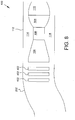
- FIG 8 is a schematic diagram of a plurality of airflow control devices 402 disposed in the inlet ducting 202 of a turbine engine 100 in accordance with some embodiments of the disclosed subject matter.
- air flow controllers 402 may be "stacked" by providing more than one controller 402 in a duct 202. As a result, air flow may be sequentially treated by each of the controllers 402.
- a first controller 402 is configured to reduce air flow distortions of a first type
- a second controller 402 is configured to reduce air flow distortions of a second type.
- multiple controllers 402 may be utilized to correct more dramatic distortions, or provide more efficient or effective corrections to air flow distortions.
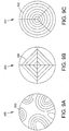
- Figure 9A is an axial profile view of an airflow control device 402 in accordance with some embodiments of the disclosed subject matter.
- Figure 9B is an axial profile view of an airflow control device 402 in accordance with some embodiments of the disclosed subject matter.
- Figure 9C is an axial profile view of an airflow control device 402 in accordance with some embodiments of the disclosed subject matter.
- the vanes 502 of the controllers 402 are configured to address a specific type of air flow distortion.
- the vanes 502 depicted in Figure 9A may be configured to improve, prevent, or correct distortions from air flow swirl patterns that develop in an inlet duct 202.
- vanes 502 of Figure 9B and 9C may not be disruptive to any specific air flow distortion, but are rather configured to improve uniformity of distribution.
- the embodiment of Figure 9B may allow for selective positioning of vanes 502 by sector of the controller 402 and/or by individual vane 502.
- the disclosed subject matter additionally provides methods of controlling or correcting detrimental air flow distortions at the inlet of a turbine engine.
- distortions in the inlet air flow are first determined. These distortions may be determined using direct measurement, for example using one or more sensors in the inlet duct to measure non-uniformity of the inlet air flow distribution. In some embodiments, these inlet air flow distortions are determined by calculations, using as their input various indirectly measured engine performance parameters. In some embodiments, modeling may predict an air flow condition within an inlet duct or elsewhere in or at the inlet of the engine based on the vehicle parameters such as, e.g., altitude, proximity to other objects, yaw, roll, or climb rate.
- one or more corrective vanes of a controller, or conditioner may be added to the air flow path, such that the flow of air over the one or more vanes conditions the air flow to improve uniformity of distribution.
- the one or more vanes may be adjusted or repositioned based on the originally determined distortion or an updated distortion. Such adjustments may be made to the vanes where the vanes are formed from a shape memory material with an embedded conductive member. By applying electrical current to the conductive member, the vanes may be heated and therefore deformed and assume an altered positioning.
- an air flow controller is adapted to be coupled axially forward of a high Mach capable engine which operates over a wide range of inlet flow temperatures due to aerothermal heating.
- the aerothermal heating at high Mach numbers can provide inlet air temperatures in excess of 1,000 degrees, thus generating far different flow fields than when the engine is operated at subsonic conditions.
- an air flow controller may be provided of shape memory material that self-adjusts based on the inlet temperatures caused by aerothermal heating, with no control system input or electrical heating required.
- Fig. 10 illustrates a method 1000 for adaptively removing the distortions prior to the compressor stage.
- a distortion of the airflow within the inlet is determined in Block 1010. This determination may be predetermined as a function of Mach number as shown in Block 1012. In predetermining the distortion, empirical simulations or experimental information may advantageously be used.
- the distortion may also be determined by sensing the airflow characteristics historically or in real time as shown in Block 1014. It is also envisioned that the distortion may be determined as a function of operational parameter of the engine and/or the aircraft as shown in Block 1016.
- the operational parameters of the engine may include throttle, thrust, rpms, temperatures, and pressures etc.
- the operation parameters of the aircraft may include angle of attack, turning, climb, roll, yaw, pitch, thrust, altitude, attitude and velocity.
- the plurality of correction vanes are positioned to mitigate the determined distortion in the airflow.
- the correction vanes are adjusted by applying electrical current through vanes constructed with shape memory material as shown in Block 1022.
- the positioning is predetermined based on an expected distortion that has also be predetermined, as shown in Block 1024.
- the positioning may be accomplished by rotation and/or axial separation of the plurality of conditioning grids relative to one another as shown in Block 1026.
- the distorted flow is then exposed to the correction vanes as shown in Block 1030.
- the determination, positioning and exposing steps may be iterative in nature.
- direct sensors located downstream of the conditioning grid, or performance parameters of the turbine may be used as feedback in assessing the efficacy of the conditioning and determining subsequent repositioning of the vanes and/or grid.
- the feedback information may be advantageously collected in a database to further refine the positioning of the vanes and assist in development in historical data for use in subsequent designs.
- the systems and methods of conditioning inlet air flow disclosed herein provide several advantages over the prior art. Most significantly, the disclosed air flow controller improves the uniformity of air flow at the inlet of a turbine engine, thus improving engine efficiency and margin to stall or surge conditions. The disclosed systems and methods carry a relatively low weight penalty, while providing greatly improved engine performance. Some of the improved engine performance gains may occur at off-design conditions, design conditions, or both.
Landscapes
- Engineering & Computer Science (AREA)
- Chemical & Material Sciences (AREA)
- Combustion & Propulsion (AREA)
- Mechanical Engineering (AREA)
- General Engineering & Computer Science (AREA)
- Physics & Mathematics (AREA)
- Geometry (AREA)
- Structures Of Non-Positive Displacement Pumps (AREA)
Claims (11)
- Verfahren zum adaptiven Beseitigen von Luftstromstörungen in einem Turbinentriebwerk, das einen Lufteinlasskanal vor der Kompressorstufe aufweist, wobei die Störungen zumindest teilweise durch die Wechselwirkung des Luftstroms mit dem Lufteinlasskanal verursacht werden, wobei das Verfahren die Schritte umfasst:Bestimmen der Störung in dem Luftstrom;Positionieren von mehreren Korrekturschaufeln basierend auf mindestens der bestimmten Störung, wobei jede der mehreren Korrekturschaufeln auf einen jeweiligen Einfallswinkel ausgerichtet ist, wenn sie eine Temperatur etwa gleich einer jeweiligen lokalen Temperatur hat; undAussetzen des Luftstroms den mehreren Korrekturschaufeln.
- Verfahren nach Anspruch 1, wobei die mehreren Korrekturschaufeln aus Formgedächtnismaterialien bereitgestellt sind.
- Verfahren nach Anspruch 1 oder 2, wobei der Schritt des Positionierens der mehreren Korrekturschaufeln das Anlegen eines elektrischen Stroms an mindestens eine jeweilige Korrekturschaufel der mehreren Korrekturschaufeln umfasst, wobei das Anlegen eines elektrischen Stroms die jeweilige Korrekturschaufel der mehreren Korrekturschaufeln von einem ersten Zustand in einen zweiten Zustand überführt.
- Verfahren nach einem der vorhergehenden Ansprüche, wobei der Schritt des Bestimmens der Störung das Vorbestimmen der Störung als Funktion der Machzahl umfasst.
- Verfahren nach einem der vorhergehenden Ansprüche, ferner umfassend das Verknüpfen einer Vielzahl lokaler Temperaturen als Funktion der Machzahl.
- Verfahren nach einem der vorhergehenden Ansprüche, ferner umfassend das Bestimmen des gewünschten Einfallswinkels für jede der mehreren Korrekturschaufeln.
- Verfahren nach einem der vorhergehenden Ansprüche, wobei der Schritt des Bestimmens der Störung das Erfassen der Luftstromeigenschaften in dem Lufteinlasskanal umfasst.
- Verfahren nach einem der vorhergehenden Ansprüche, wobei der Schritt des Bestimmens der Störung das Bestimmen aktueller Betriebsparameter umfasst.
- Verfahren nach Anspruch 8, wobei die Betriebsparameter aus der Gruppe ausgewählt sind, die aus Anstellwinkel, Drehen, Steigen, Rollen, Gieren, Neigen, Schub, Höhe, Fluglage und Geschwindigkeit besteht.
- Verfahren nach Anspruch 8, wobei die Betriebsparameter aus der Gruppe ausgewählt sind, die aus Start, Landung, Fliegen mit Reisegeschwindigkeit, Warteflug, Überschallflug und Unterschallflug besteht.
- Turbineneinlasskanal, umfassend:einen Luftdurchgang, der durch den Einlasskanal definiert ist, wobei der Luftdurchgang einen Mittelweg aufweist, der den Luftstrom durch den Einlasskanal definiert, wobei der Mittelweg mindestens eine Krümmung umfasst; undein Konditionierungsgitter mit mehreren Schaufeln, die sich innerhalb des Durchgangs befinden, wobei die mehreren Schaufeln mehrere Formgedächtnisschaufeln umfassen, wobei die mindestens eine Krümmung stromaufwärts des Konditionierungsgitters positioniert ist und wobei jede der mehreren Schaufeln konfiguriert ist, um den Luftstrom stromabwärts der mindestens einen Krümmung zu verändern.
Applications Claiming Priority (1)
| Application Number | Priority Date | Filing Date | Title |
|---|---|---|---|
| US15/363,654 US11149639B2 (en) | 2016-11-29 | 2016-11-29 | Systems and methods of reducing distortions of the inlet airflow to a turbomachine |
Publications (2)
| Publication Number | Publication Date |
|---|---|
| EP3348811A1 EP3348811A1 (de) | 2018-07-18 |
| EP3348811B1 true EP3348811B1 (de) | 2020-08-05 |
Family
ID=60201872
Family Applications (1)
| Application Number | Title | Priority Date | Filing Date |
|---|---|---|---|
| EP17199340.5A Active EP3348811B1 (de) | 2016-11-29 | 2017-10-31 | Turbineneinlauf und verfahren zur verminderung eines ungleichförmigen eingangsluftstroms zu einer turbomaschine |
Country Status (3)
| Country | Link |
|---|---|
| US (1) | US11149639B2 (de) |
| EP (1) | EP3348811B1 (de) |
| CA (1) | CA2978292A1 (de) |
Families Citing this family (17)
| Publication number | Priority date | Publication date | Assignee | Title |
|---|---|---|---|---|
| US10704418B2 (en) | 2016-08-11 | 2020-07-07 | General Electric Company | Inlet assembly for an aircraft aft fan |
| US20200080477A1 (en) * | 2018-09-07 | 2020-03-12 | United Technologies Corporation | Prediction of inlet distortion of boundary layer ingesting propulsion system |
| CN110795869B (zh) * | 2020-01-06 | 2020-04-07 | 中国人民解放军国防科技大学 | 流场数据的数值计算方法和装置 |
| CN111896263B (zh) * | 2020-08-07 | 2022-05-31 | 中国航空工业集团公司沈阳空气动力研究所 | 一种栅指式畸变发生器 |
| US11814154B2 (en) * | 2020-08-31 | 2023-11-14 | General Electric Company | Pitch angles of an aircraft engine rotor assembly |
| US12479587B2 (en) | 2020-12-21 | 2025-11-25 | General Electric Company Polska Sp. Z O.O. | Skeleton screen for an air intake portion of a machine |
| CN113217471B (zh) * | 2021-06-21 | 2022-10-28 | 中国航发沈阳发动机研究所 | 一种温度畸变条件下发动机稳定裕度保持方法 |
| CN113987812A (zh) * | 2021-10-29 | 2022-01-28 | 中国航发沈阳发动机研究所 | 一种航空发动机进口动态畸变流场旋涡尺度量化方法 |
| CN114542295A (zh) * | 2021-12-29 | 2022-05-27 | 中国航空工业集团公司沈阳飞机设计研究所 | 一种提高飞机推进系统稳定性的方法及装置 |
| US12025059B1 (en) | 2022-12-27 | 2024-07-02 | Rolls-Royce North American Technologies Inc. | Distributed electric tip fans for distortion tolerance of turbofan engines |
| US12065979B2 (en) | 2022-12-27 | 2024-08-20 | Rolls-Royce North American Technologies Inc. | Distributed electric and hybrid fans for distortion tolerance of turbofan engines |
| US11835064B1 (en) | 2022-12-27 | 2023-12-05 | Rolls-Royce North American Technologies Inc. | Electric fan array for distortion tolerance of turbofan engines |
| US12065258B2 (en) | 2023-01-25 | 2024-08-20 | Rolls-Royce North American Technologies Inc. | Multiple intake distortion adaptive fan for gas turbine engine |
| US12276227B1 (en) | 2023-10-23 | 2025-04-15 | General Electric Company | Turbine engine screen |
| CN117436210B (zh) * | 2023-12-18 | 2024-03-19 | 潍柴动力股份有限公司 | 一种拓宽流量槽与叶轮的联合设计方法及装置 |
| CN117906963B (zh) * | 2024-03-05 | 2025-11-07 | 中国航发湖南动力机械研究所 | 喷射式温度畸变发生器 |
| US12503978B1 (en) | 2024-06-21 | 2025-12-23 | Rolls-Royce North American Technologies Inc. | Inlets for gas turbine engine fans with distortion tolerance |
Family Cites Families (24)
| Publication number | Priority date | Publication date | Assignee | Title |
|---|---|---|---|---|
| US2735612A (en) * | 1956-02-21 | hausmann | ||
| GB1543584A (en) | 1976-10-20 | 1979-04-04 | Secr Defence | De-icing of the air intakes of gas turbine engines |
| US5448881A (en) * | 1993-06-09 | 1995-09-12 | United Technologies Corporation | Gas turbine engine control based on inlet pressure distortion |
| US6089505A (en) | 1997-07-22 | 2000-07-18 | Mcdonnell Douglas Corporation | Mission adaptive inlet |
| US6371414B1 (en) * | 1999-07-16 | 2002-04-16 | Lockheed Martin Corporation | System and method for manipulating and controlling fluid flow over a surface |
| US6715983B2 (en) | 2001-09-27 | 2004-04-06 | General Electric Company | Method and apparatus for reducing distortion losses induced to gas turbine engine airflow |
| US6959552B2 (en) | 2004-03-18 | 2005-11-01 | Pratt & Whitney Canada Corp. | Gas turbine inlet flow straightener |
| SE527828C2 (sv) * | 2004-11-05 | 2006-06-13 | Volvo Aero Corp | Framdrivningssystem för en farkost |
| GB0519502D0 (en) * | 2005-09-24 | 2005-11-02 | Rolls Royce Plc | Vane assembly |
| US7637455B2 (en) * | 2006-04-12 | 2009-12-29 | The Boeing Company | Inlet distortion and recovery control system |
| US7784732B2 (en) * | 2007-01-04 | 2010-08-31 | The United States Of America As Represented By The Administrator Of The National Aeronautics And Space Administration | Boundary-layer-ingesting inlet flow control system |
| US8348600B2 (en) | 2008-05-27 | 2013-01-08 | United Technologies Corporation | Gas turbine engine having controllable inlet guide vanes |
| US8240616B2 (en) * | 2009-04-22 | 2012-08-14 | Miller Daniel N | Method and system for global flow field management using distributed, surface-embedded, nano-scale boundary layer actuation |
| US20110011055A1 (en) * | 2009-07-17 | 2011-01-20 | Thomas Jay Troy | Jet engine air intake guard |
| US20130074512A1 (en) * | 2011-09-23 | 2013-03-28 | Steven William Tillery | Inlet fluid flow and impingement angle control |
| US9194301B2 (en) * | 2012-06-04 | 2015-11-24 | United Technologies Corporation | Protecting the operating margin of a gas turbine engine having variable vanes from aerodynamic distortion |
| US9932121B2 (en) * | 2012-06-22 | 2018-04-03 | United Technologies Corporation | Turbomachine flow stability enhancement device control |
| US9885291B2 (en) | 2012-08-09 | 2018-02-06 | Snecma | Turbomachine comprising a plurality of fixed radial blades mounted upstream of the fan |
| CA2925038C (en) | 2012-09-27 | 2020-08-25 | Shield Aerodynamics Llc | Environmental defense shield |
| US9145198B1 (en) | 2013-01-04 | 2015-09-29 | The Boeing Company | Variable camber airfoil system |
| US9334807B2 (en) * | 2014-05-13 | 2016-05-10 | The Boeing Company | Methods and apparatus to determine airflow conditions at an inlet of an engine |
| US20160012159A1 (en) * | 2014-07-10 | 2016-01-14 | Anthony M. Ferrar | Design And Manufacture Of Generalized Flow Profile-Producing Devices |
| US10794281B2 (en) | 2016-02-02 | 2020-10-06 | General Electric Company | Gas turbine engine having instrumented airflow path components |
| US10006833B1 (en) * | 2016-08-24 | 2018-06-26 | Northrop Grumman Systems Corporation | Method for vortex generator array sizing and placement within offset diffusers |
-
2016
- 2016-11-29 US US15/363,654 patent/US11149639B2/en active Active
-
2017
- 2017-09-05 CA CA2978292A patent/CA2978292A1/en active Pending
- 2017-10-31 EP EP17199340.5A patent/EP3348811B1/de active Active
Non-Patent Citations (1)
| Title |
|---|
| None * |
Also Published As
| Publication number | Publication date |
|---|---|
| EP3348811A1 (de) | 2018-07-18 |
| CA2978292A1 (en) | 2018-05-29 |
| US20180149084A1 (en) | 2018-05-31 |
| US11149639B2 (en) | 2021-10-19 |
Similar Documents
| Publication | Publication Date | Title |
|---|---|---|
| EP3348811B1 (de) | Turbineneinlauf und verfahren zur verminderung eines ungleichförmigen eingangsluftstroms zu einer turbomaschine | |
| US11879343B2 (en) | Systems for controlling variable outlet guide vanes | |
| JP6431946B2 (ja) | ガスタービンエンジンの気流歪曲を調整する可動導入口 | |
| US11073090B2 (en) | Valved airflow passage assembly for adjusting airflow distortion in gas turbine engine | |
| EP2952710B1 (de) | Modellbasierte, optimale steuerung des strömungsabrissbereichs in einem flugzeugtriebwerk | |
| US20090297334A1 (en) | Gas turbine engine having controllable inlet guide vanes | |
| US7444802B2 (en) | Gas turbine engine including stator vanes having variable camber and stagger configurations at different circumferential positions | |
| EP3335136B1 (de) | Verfahren zur vorhersage von pumpen in einem gasverdichter | |
| US20230358169A1 (en) | Active compressor stall recovery | |
| CN107023405A (zh) | 用于可变桨距风扇发动机和涡轮轴、涡轮螺旋桨发动机的推力调度方法 | |
| CN112302987B (zh) | 应对温度畸变的航空发动机压缩部件可调导叶调节方法 | |
| Hasegawa et al. | Development of highly loaded fan with tandem cascade | |
| US12320260B2 (en) | Segmented variable fan outlet guide vane with cam assembly and unique actuation mechanisms | |
| US10822991B2 (en) | Method and apparatus for active clearance control on gas turbine engines | |
| US12398648B2 (en) | Segmented variable fan outlet guide vane with cam assembly and pass through actuation mechanisms | |
| GB2458903A (en) | A method for determining total pressure distribution across a fan entry plane | |
| EP3034815B1 (de) | Kerntriebwerkgehäuseheizung für gasturbinenmotoren | |
| EP3712737B1 (de) | Signalantwortüberwachung für turbinenmotoren | |
| US11105269B2 (en) | Method of control of three spool gas turbine engine | |
| EP4119775A1 (de) | Aktives spielsteuersystem und verfahren für einen flugzeugmotor | |
| EP4450792B1 (de) | Variable leitschaufelanordnung und steuerungssystem dafür | |
| US12546231B2 (en) | High-pressure rotor control system | |
| US20240159185A1 (en) | Systems and methods for controlling strut positions for an aircraft propulsion system strut assembly | |
| US20250075627A1 (en) | Systems and methods of active clearance control in a gas turbine engine | |
| CN120520692A (zh) | 低桨距保护控制系统 |
Legal Events
| Date | Code | Title | Description |
|---|---|---|---|
| PUAI | Public reference made under article 153(3) epc to a published international application that has entered the european phase |
Free format text: ORIGINAL CODE: 0009012 |
|
| STAA | Information on the status of an ep patent application or granted ep patent |
Free format text: STATUS: THE APPLICATION HAS BEEN PUBLISHED |
|
| AK | Designated contracting states |
Kind code of ref document: A1 Designated state(s): AL AT BE BG CH CY CZ DE DK EE ES FI FR GB GR HR HU IE IS IT LI LT LU LV MC MK MT NL NO PL PT RO RS SE SI SK SM TR |
|
| AX | Request for extension of the european patent |
Extension state: BA ME |
|
| STAA | Information on the status of an ep patent application or granted ep patent |
Free format text: STATUS: REQUEST FOR EXAMINATION WAS MADE |
|
| 17P | Request for examination filed |
Effective date: 20190118 |
|
| RBV | Designated contracting states (corrected) |
Designated state(s): AL AT BE BG CH CY CZ DE DK EE ES FI FR GB GR HR HU IE IS IT LI LT LU LV MC MK MT NL NO PL PT RO RS SE SI SK SM TR |
|
| GRAP | Despatch of communication of intention to grant a patent |
Free format text: ORIGINAL CODE: EPIDOSNIGR1 |
|
| STAA | Information on the status of an ep patent application or granted ep patent |
Free format text: STATUS: GRANT OF PATENT IS INTENDED |
|
| INTG | Intention to grant announced |
Effective date: 20200518 |
|
| GRAS | Grant fee paid |
Free format text: ORIGINAL CODE: EPIDOSNIGR3 |
|
| GRAA | (expected) grant |
Free format text: ORIGINAL CODE: 0009210 |
|
| STAA | Information on the status of an ep patent application or granted ep patent |
Free format text: STATUS: THE PATENT HAS BEEN GRANTED |
|
| AK | Designated contracting states |
Kind code of ref document: B1 Designated state(s): AL AT BE BG CH CY CZ DE DK EE ES FI FR GB GR HR HU IE IS IT LI LT LU LV MC MK MT NL NO PL PT RO RS SE SI SK SM TR |
|
| REG | Reference to a national code |
Ref country code: GB Ref legal event code: FG4D |
|
| REG | Reference to a national code |
Ref country code: CH Ref legal event code: EP |
|
| REG | Reference to a national code |
Ref country code: AT Ref legal event code: REF Ref document number: 1299013 Country of ref document: AT Kind code of ref document: T Effective date: 20200815 |
|
| REG | Reference to a national code |
Ref country code: DE Ref legal event code: R096 Ref document number: 602017020942 Country of ref document: DE |
|
| REG | Reference to a national code |
Ref country code: IE Ref legal event code: FG4D |
|
| REG | Reference to a national code |
Ref country code: LT Ref legal event code: MG4D |
|
| REG | Reference to a national code |
Ref country code: NL Ref legal event code: MP Effective date: 20200805 |
|
| REG | Reference to a national code |
Ref country code: AT Ref legal event code: MK05 Ref document number: 1299013 Country of ref document: AT Kind code of ref document: T Effective date: 20200805 |
|
| PG25 | Lapsed in a contracting state [announced via postgrant information from national office to epo] |
Ref country code: ES Free format text: LAPSE BECAUSE OF FAILURE TO SUBMIT A TRANSLATION OF THE DESCRIPTION OR TO PAY THE FEE WITHIN THE PRESCRIBED TIME-LIMIT Effective date: 20200805 Ref country code: PT Free format text: LAPSE BECAUSE OF FAILURE TO SUBMIT A TRANSLATION OF THE DESCRIPTION OR TO PAY THE FEE WITHIN THE PRESCRIBED TIME-LIMIT Effective date: 20201207 Ref country code: HR Free format text: LAPSE BECAUSE OF FAILURE TO SUBMIT A TRANSLATION OF THE DESCRIPTION OR TO PAY THE FEE WITHIN THE PRESCRIBED TIME-LIMIT Effective date: 20200805 Ref country code: LT Free format text: LAPSE BECAUSE OF FAILURE TO SUBMIT A TRANSLATION OF THE DESCRIPTION OR TO PAY THE FEE WITHIN THE PRESCRIBED TIME-LIMIT Effective date: 20200805 Ref country code: AT Free format text: LAPSE BECAUSE OF FAILURE TO SUBMIT A TRANSLATION OF THE DESCRIPTION OR TO PAY THE FEE WITHIN THE PRESCRIBED TIME-LIMIT Effective date: 20200805 Ref country code: BG Free format text: LAPSE BECAUSE OF FAILURE TO SUBMIT A TRANSLATION OF THE DESCRIPTION OR TO PAY THE FEE WITHIN THE PRESCRIBED TIME-LIMIT Effective date: 20201105 Ref country code: SE Free format text: LAPSE BECAUSE OF FAILURE TO SUBMIT A TRANSLATION OF THE DESCRIPTION OR TO PAY THE FEE WITHIN THE PRESCRIBED TIME-LIMIT Effective date: 20200805 Ref country code: GR Free format text: LAPSE BECAUSE OF FAILURE TO SUBMIT A TRANSLATION OF THE DESCRIPTION OR TO PAY THE FEE WITHIN THE PRESCRIBED TIME-LIMIT Effective date: 20201106 Ref country code: FI Free format text: LAPSE BECAUSE OF FAILURE TO SUBMIT A TRANSLATION OF THE DESCRIPTION OR TO PAY THE FEE WITHIN THE PRESCRIBED TIME-LIMIT Effective date: 20200805 Ref country code: NO Free format text: LAPSE BECAUSE OF FAILURE TO SUBMIT A TRANSLATION OF THE DESCRIPTION OR TO PAY THE FEE WITHIN THE PRESCRIBED TIME-LIMIT Effective date: 20201105 |
|
| PG25 | Lapsed in a contracting state [announced via postgrant information from national office to epo] |
Ref country code: NL Free format text: LAPSE BECAUSE OF FAILURE TO SUBMIT A TRANSLATION OF THE DESCRIPTION OR TO PAY THE FEE WITHIN THE PRESCRIBED TIME-LIMIT Effective date: 20200805 Ref country code: LV Free format text: LAPSE BECAUSE OF FAILURE TO SUBMIT A TRANSLATION OF THE DESCRIPTION OR TO PAY THE FEE WITHIN THE PRESCRIBED TIME-LIMIT Effective date: 20200805 Ref country code: RS Free format text: LAPSE BECAUSE OF FAILURE TO SUBMIT A TRANSLATION OF THE DESCRIPTION OR TO PAY THE FEE WITHIN THE PRESCRIBED TIME-LIMIT Effective date: 20200805 Ref country code: PL Free format text: LAPSE BECAUSE OF FAILURE TO SUBMIT A TRANSLATION OF THE DESCRIPTION OR TO PAY THE FEE WITHIN THE PRESCRIBED TIME-LIMIT Effective date: 20200805 Ref country code: IS Free format text: LAPSE BECAUSE OF FAILURE TO SUBMIT A TRANSLATION OF THE DESCRIPTION OR TO PAY THE FEE WITHIN THE PRESCRIBED TIME-LIMIT Effective date: 20201205 |
|
| PG25 | Lapsed in a contracting state [announced via postgrant information from national office to epo] |
Ref country code: CZ Free format text: LAPSE BECAUSE OF FAILURE TO SUBMIT A TRANSLATION OF THE DESCRIPTION OR TO PAY THE FEE WITHIN THE PRESCRIBED TIME-LIMIT Effective date: 20200805 Ref country code: DK Free format text: LAPSE BECAUSE OF FAILURE TO SUBMIT A TRANSLATION OF THE DESCRIPTION OR TO PAY THE FEE WITHIN THE PRESCRIBED TIME-LIMIT Effective date: 20200805 Ref country code: RO Free format text: LAPSE BECAUSE OF FAILURE TO SUBMIT A TRANSLATION OF THE DESCRIPTION OR TO PAY THE FEE WITHIN THE PRESCRIBED TIME-LIMIT Effective date: 20200805 Ref country code: SM Free format text: LAPSE BECAUSE OF FAILURE TO SUBMIT A TRANSLATION OF THE DESCRIPTION OR TO PAY THE FEE WITHIN THE PRESCRIBED TIME-LIMIT Effective date: 20200805 Ref country code: EE Free format text: LAPSE BECAUSE OF FAILURE TO SUBMIT A TRANSLATION OF THE DESCRIPTION OR TO PAY THE FEE WITHIN THE PRESCRIBED TIME-LIMIT Effective date: 20200805 |
|
| REG | Reference to a national code |
Ref country code: DE Ref legal event code: R119 Ref document number: 602017020942 Country of ref document: DE |
|
| PG25 | Lapsed in a contracting state [announced via postgrant information from national office to epo] |
Ref country code: AL Free format text: LAPSE BECAUSE OF FAILURE TO SUBMIT A TRANSLATION OF THE DESCRIPTION OR TO PAY THE FEE WITHIN THE PRESCRIBED TIME-LIMIT Effective date: 20200805 |
|
| REG | Reference to a national code |
Ref country code: CH Ref legal event code: PL |
|
| PLBE | No opposition filed within time limit |
Free format text: ORIGINAL CODE: 0009261 |
|
| STAA | Information on the status of an ep patent application or granted ep patent |
Free format text: STATUS: NO OPPOSITION FILED WITHIN TIME LIMIT |
|
| PG25 | Lapsed in a contracting state [announced via postgrant information from national office to epo] |
Ref country code: SK Free format text: LAPSE BECAUSE OF FAILURE TO SUBMIT A TRANSLATION OF THE DESCRIPTION OR TO PAY THE FEE WITHIN THE PRESCRIBED TIME-LIMIT Effective date: 20200805 Ref country code: LU Free format text: LAPSE BECAUSE OF NON-PAYMENT OF DUE FEES Effective date: 20201031 Ref country code: MC Free format text: LAPSE BECAUSE OF FAILURE TO SUBMIT A TRANSLATION OF THE DESCRIPTION OR TO PAY THE FEE WITHIN THE PRESCRIBED TIME-LIMIT Effective date: 20200805 |
|
| 26N | No opposition filed |
Effective date: 20210507 |
|
| REG | Reference to a national code |
Ref country code: BE Ref legal event code: MM Effective date: 20201031 |
|
| PG25 | Lapsed in a contracting state [announced via postgrant information from national office to epo] |
Ref country code: IT Free format text: LAPSE BECAUSE OF FAILURE TO SUBMIT A TRANSLATION OF THE DESCRIPTION OR TO PAY THE FEE WITHIN THE PRESCRIBED TIME-LIMIT Effective date: 20200805 Ref country code: DE Free format text: LAPSE BECAUSE OF NON-PAYMENT OF DUE FEES Effective date: 20210501 |
|
| PG25 | Lapsed in a contracting state [announced via postgrant information from national office to epo] |
Ref country code: BE Free format text: LAPSE BECAUSE OF NON-PAYMENT OF DUE FEES Effective date: 20201031 Ref country code: CH Free format text: LAPSE BECAUSE OF NON-PAYMENT OF DUE FEES Effective date: 20201031 Ref country code: SI Free format text: LAPSE BECAUSE OF FAILURE TO SUBMIT A TRANSLATION OF THE DESCRIPTION OR TO PAY THE FEE WITHIN THE PRESCRIBED TIME-LIMIT Effective date: 20200805 Ref country code: LI Free format text: LAPSE BECAUSE OF NON-PAYMENT OF DUE FEES Effective date: 20201031 |
|
| PG25 | Lapsed in a contracting state [announced via postgrant information from national office to epo] |
Ref country code: IE Free format text: LAPSE BECAUSE OF NON-PAYMENT OF DUE FEES Effective date: 20201031 |
|
| PG25 | Lapsed in a contracting state [announced via postgrant information from national office to epo] |
Ref country code: TR Free format text: LAPSE BECAUSE OF FAILURE TO SUBMIT A TRANSLATION OF THE DESCRIPTION OR TO PAY THE FEE WITHIN THE PRESCRIBED TIME-LIMIT Effective date: 20200805 Ref country code: MT Free format text: LAPSE BECAUSE OF FAILURE TO SUBMIT A TRANSLATION OF THE DESCRIPTION OR TO PAY THE FEE WITHIN THE PRESCRIBED TIME-LIMIT Effective date: 20200805 Ref country code: CY Free format text: LAPSE BECAUSE OF FAILURE TO SUBMIT A TRANSLATION OF THE DESCRIPTION OR TO PAY THE FEE WITHIN THE PRESCRIBED TIME-LIMIT Effective date: 20200805 |
|
| GBPC | Gb: european patent ceased through non-payment of renewal fee |
Effective date: 20211031 |
|
| PG25 | Lapsed in a contracting state [announced via postgrant information from national office to epo] |
Ref country code: MK Free format text: LAPSE BECAUSE OF FAILURE TO SUBMIT A TRANSLATION OF THE DESCRIPTION OR TO PAY THE FEE WITHIN THE PRESCRIBED TIME-LIMIT Effective date: 20200805 |
|
| PG25 | Lapsed in a contracting state [announced via postgrant information from national office to epo] |
Ref country code: GB Free format text: LAPSE BECAUSE OF NON-PAYMENT OF DUE FEES Effective date: 20211031 |
|
| P01 | Opt-out of the competence of the unified patent court (upc) registered |
Effective date: 20230528 |
|
| PGFP | Annual fee paid to national office [announced via postgrant information from national office to epo] |
Ref country code: FR Payment date: 20251027 Year of fee payment: 9 |