EP3348671B1 - Space craft having a fuel production apparatus - Google Patents
Space craft having a fuel production apparatus Download PDFInfo
- Publication number
- EP3348671B1 EP3348671B1 EP17151463.1A EP17151463A EP3348671B1 EP 3348671 B1 EP3348671 B1 EP 3348671B1 EP 17151463 A EP17151463 A EP 17151463A EP 3348671 B1 EP3348671 B1 EP 3348671B1
- Authority
- EP
- European Patent Office
- Prior art keywords
- water
- hydrogen
- electrolysis process
- pressure
- oxygen
- Prior art date
- Legal status (The legal status is an assumption and is not a legal conclusion. Google has not performed a legal analysis and makes no representation as to the accuracy of the status listed.)
- Active
Links
- 238000004519 manufacturing process Methods 0.000 title claims 2
- 239000000446 fuel Substances 0.000 title description 26
- 238000005868 electrolysis reaction Methods 0.000 claims description 87
- 238000000034 method Methods 0.000 claims description 87
- XLYOFNOQVPJJNP-UHFFFAOYSA-N water Substances O XLYOFNOQVPJJNP-UHFFFAOYSA-N 0.000 claims description 78
- UFHFLCQGNIYNRP-UHFFFAOYSA-N Hydrogen Chemical compound [H][H] UFHFLCQGNIYNRP-UHFFFAOYSA-N 0.000 claims description 57
- 239000001257 hydrogen Substances 0.000 claims description 55
- 229910052739 hydrogen Inorganic materials 0.000 claims description 55
- QVGXLLKOCUKJST-UHFFFAOYSA-N atomic oxygen Chemical compound [O] QVGXLLKOCUKJST-UHFFFAOYSA-N 0.000 claims description 41
- 239000001301 oxygen Substances 0.000 claims description 41
- 229910052760 oxygen Inorganic materials 0.000 claims description 41
- 238000003860 storage Methods 0.000 claims description 38
- 239000007789 gas Substances 0.000 claims description 27
- 239000003792 electrolyte Substances 0.000 claims description 11
- 230000005484 gravity Effects 0.000 claims description 10
- 239000011159 matrix material Substances 0.000 claims description 8
- 239000012530 fluid Substances 0.000 description 23
- 239000003380 propellant Substances 0.000 description 10
- 238000010586 diagram Methods 0.000 description 7
- 230000001133 acceleration Effects 0.000 description 4
- 230000000694 effects Effects 0.000 description 4
- 238000012432 intermediate storage Methods 0.000 description 4
- MYMOFIZGZYHOMD-UHFFFAOYSA-N Dioxygen Chemical compound O=O MYMOFIZGZYHOMD-UHFFFAOYSA-N 0.000 description 3
- 230000008878 coupling Effects 0.000 description 3
- 238000010168 coupling process Methods 0.000 description 3
- 238000005859 coupling reaction Methods 0.000 description 3
- 229910001882 dioxygen Inorganic materials 0.000 description 3
- 239000012528 membrane Substances 0.000 description 3
- OAKJQQAXSVQMHS-UHFFFAOYSA-N Hydrazine Chemical compound NN OAKJQQAXSVQMHS-UHFFFAOYSA-N 0.000 description 2
- 239000002775 capsule Substances 0.000 description 2
- 238000013461 design Methods 0.000 description 2
- 230000001788 irregular Effects 0.000 description 2
- 230000007774 longterm Effects 0.000 description 2
- 238000005259 measurement Methods 0.000 description 2
- 239000000523 sample Substances 0.000 description 2
- 238000007789 sealing Methods 0.000 description 2
- 239000000243 solution Substances 0.000 description 2
- 238000013022 venting Methods 0.000 description 2
- PEDCQBHIVMGVHV-UHFFFAOYSA-N Glycerine Chemical compound OCC(O)CO PEDCQBHIVMGVHV-UHFFFAOYSA-N 0.000 description 1
- 235000015842 Hesperis Nutrition 0.000 description 1
- 235000012633 Iberis amara Nutrition 0.000 description 1
- KWYUFKZDYYNOTN-UHFFFAOYSA-M Potassium hydroxide Chemical compound [OH-].[K+] KWYUFKZDYYNOTN-UHFFFAOYSA-M 0.000 description 1
- 239000012670 alkaline solution Substances 0.000 description 1
- 238000001816 cooling Methods 0.000 description 1
- 238000011161 development Methods 0.000 description 1
- 230000018109 developmental process Effects 0.000 description 1
- 239000012777 electrically insulating material Substances 0.000 description 1
- 238000005516 engineering process Methods 0.000 description 1
- 150000002431 hydrogen Chemical class 0.000 description 1
- 239000000463 material Substances 0.000 description 1
- 230000000737 periodic effect Effects 0.000 description 1
- 238000006479 redox reaction Methods 0.000 description 1
- 239000000126 substance Substances 0.000 description 1
- 238000009423 ventilation Methods 0.000 description 1
Images


Classifications
-
- B—PERFORMING OPERATIONS; TRANSPORTING
- B64—AIRCRAFT; AVIATION; COSMONAUTICS
- B64G—COSMONAUTICS; VEHICLES OR EQUIPMENT THEREFOR
- B64G1/00—Cosmonautic vehicles
- B64G1/22—Parts of, or equipment specially adapted for fitting in or to, cosmonautic vehicles
- B64G1/40—Arrangements or adaptations of propulsion systems
- B64G1/402—Propellant tanks; Feeding propellants
-
- B—PERFORMING OPERATIONS; TRANSPORTING
- B64—AIRCRAFT; AVIATION; COSMONAUTICS
- B64G—COSMONAUTICS; VEHICLES OR EQUIPMENT THEREFOR
- B64G1/00—Cosmonautic vehicles
- B64G1/22—Parts of, or equipment specially adapted for fitting in or to, cosmonautic vehicles
- B64G1/66—Arrangements or adaptations of apparatus or instruments, not otherwise provided for
-
- C—CHEMISTRY; METALLURGY
- C25—ELECTROLYTIC OR ELECTROPHORETIC PROCESSES; APPARATUS THEREFOR
- C25B—ELECTROLYTIC OR ELECTROPHORETIC PROCESSES FOR THE PRODUCTION OF COMPOUNDS OR NON-METALS; APPARATUS THEREFOR
- C25B1/00—Electrolytic production of inorganic compounds or non-metals
- C25B1/01—Products
- C25B1/02—Hydrogen or oxygen
- C25B1/04—Hydrogen or oxygen by electrolysis of water
-
- C—CHEMISTRY; METALLURGY
- C25—ELECTROLYTIC OR ELECTROPHORETIC PROCESSES; APPARATUS THEREFOR
- C25B—ELECTROLYTIC OR ELECTROPHORETIC PROCESSES FOR THE PRODUCTION OF COMPOUNDS OR NON-METALS; APPARATUS THEREFOR
- C25B15/00—Operating or servicing cells
- C25B15/08—Supplying or removing reactants or electrolytes; Regeneration of electrolytes
-
- C—CHEMISTRY; METALLURGY
- C25—ELECTROLYTIC OR ELECTROPHORETIC PROCESSES; APPARATUS THEREFOR
- C25B—ELECTROLYTIC OR ELECTROPHORETIC PROCESSES FOR THE PRODUCTION OF COMPOUNDS OR NON-METALS; APPARATUS THEREFOR
- C25B9/00—Cells or assemblies of cells; Constructional parts of cells; Assemblies of constructional parts, e.g. electrode-diaphragm assemblies; Process-related cell features
- C25B9/17—Cells comprising dimensionally-stable non-movable electrodes; Assemblies of constructional parts thereof
- C25B9/19—Cells comprising dimensionally-stable non-movable electrodes; Assemblies of constructional parts thereof with diaphragms
-
- C—CHEMISTRY; METALLURGY
- C25—ELECTROLYTIC OR ELECTROPHORETIC PROCESSES; APPARATUS THEREFOR
- C25B—ELECTROLYTIC OR ELECTROPHORETIC PROCESSES FOR THE PRODUCTION OF COMPOUNDS OR NON-METALS; APPARATUS THEREFOR
- C25B9/00—Cells or assemblies of cells; Constructional parts of cells; Assemblies of constructional parts, e.g. electrode-diaphragm assemblies; Process-related cell features
- C25B9/70—Assemblies comprising two or more cells
- C25B9/73—Assemblies comprising two or more cells of the filter-press type
-
- F—MECHANICAL ENGINEERING; LIGHTING; HEATING; WEAPONS; BLASTING
- F02—COMBUSTION ENGINES; HOT-GAS OR COMBUSTION-PRODUCT ENGINE PLANTS
- F02K—JET-PROPULSION PLANTS
- F02K9/00—Rocket-engine plants, i.e. plants carrying both fuel and oxidant therefor; Control thereof
- F02K9/42—Rocket-engine plants, i.e. plants carrying both fuel and oxidant therefor; Control thereof using liquid or gaseous propellants
- F02K9/425—Propellants
-
- F—MECHANICAL ENGINEERING; LIGHTING; HEATING; WEAPONS; BLASTING
- F02—COMBUSTION ENGINES; HOT-GAS OR COMBUSTION-PRODUCT ENGINE PLANTS
- F02K—JET-PROPULSION PLANTS
- F02K9/00—Rocket-engine plants, i.e. plants carrying both fuel and oxidant therefor; Control thereof
- F02K9/42—Rocket-engine plants, i.e. plants carrying both fuel and oxidant therefor; Control thereof using liquid or gaseous propellants
- F02K9/44—Feeding propellants
- F02K9/50—Feeding propellants using pressurised fluid to pressurise the propellants
-
- B—PERFORMING OPERATIONS; TRANSPORTING
- B64—AIRCRAFT; AVIATION; COSMONAUTICS
- B64G—COSMONAUTICS; VEHICLES OR EQUIPMENT THEREFOR
- B64G1/00—Cosmonautic vehicles
- B64G1/10—Artificial satellites; Systems of such satellites; Interplanetary vehicles
-
- Y—GENERAL TAGGING OF NEW TECHNOLOGICAL DEVELOPMENTS; GENERAL TAGGING OF CROSS-SECTIONAL TECHNOLOGIES SPANNING OVER SEVERAL SECTIONS OF THE IPC; TECHNICAL SUBJECTS COVERED BY FORMER USPC CROSS-REFERENCE ART COLLECTIONS [XRACs] AND DIGESTS
- Y02—TECHNOLOGIES OR APPLICATIONS FOR MITIGATION OR ADAPTATION AGAINST CLIMATE CHANGE
- Y02E—REDUCTION OF GREENHOUSE GAS [GHG] EMISSIONS, RELATED TO ENERGY GENERATION, TRANSMISSION OR DISTRIBUTION
- Y02E60/00—Enabling technologies; Technologies with a potential or indirect contribution to GHG emissions mitigation
- Y02E60/30—Hydrogen technology
- Y02E60/36—Hydrogen production from non-carbon containing sources, e.g. by water electrolysis
Definitions
- the invention relates to a spacecraft with a propellant generating device.
- a propellant generating device for a spacecraft has been proposed. From the U.S. 3,905,884 a propulsion generating device for a spacecraft with an electrolyzer, which is provided for generating hydrogen and oxygen, is already known. Furthermore, from the US 2014/363757 A1 as well as from the US 2014/224668 A1 in each case devices with an electrolyser, which is provided for generating hydrogen, are known. XP 055556467 also discloses a propellant generating device for a spacecraft with an electrolyzer for generating hydrogen and oxygen in connection with the use of thrusters for maneuvering the spacecraft.
- the object of the invention is in particular to provide a generic device with improved properties with regard to a simple and rapid on-site generation of propellant for a spacecraft.
- the object is achieved according to the invention by the features of claim 1, while advantageous configurations and developments of the invention can be found in the subclaims.
- the invention proposes a spacecraft, in particular a satellite, with a propellant generating device, with at least one electrolyzer, which is provided for the recurring generation of hydrogen and oxygen and has at least one electrolytic cell, which comprises at least one alkaline electrolyte.
- electrolyser energy is absorbed by a Electric current split water into molecular oxygen and molecular hydrogen.
- a “spacecraft” is to be understood as meaning, in particular, a human-made missile for space.
- spacecraft that appear sensible to a person skilled in the art are conceivable, such as rockets, space probes, space shuttles, spaceships, space capsules, space stations and / or particularly preferably satellites.
- electrolysis cell is to be understood in this context in particular as a unit with at least two electrodes, one of which is preferably designed as a hydrogen electrode and one as an oxygen electrode, with a circuit connecting the two electrodes, with at least one arranged at least between the two electrodes Electrolyte and / or with an electrolyte-filled or ion-conducting membrane arranged at least between the two electrodes.
- the unit is intended to carry out a redox reaction in which, using energy in the form of electrical power, water is split to generate a first gas, namely molecular hydrogen, and a second gas, namely molecular oxygen.
- a first gas namely molecular hydrogen
- a second gas namely molecular oxygen.
- An "electrolyte” is to be understood in particular as an ion-conducting substance, preferably in the form of a solution, for example an alkaline solution.
- alkaline electrolytes that appear sensible to a person skilled in the art are conceivable, such as, for example, a potassium hydroxide solution and / or a hydrazine solution.
- “Provided” is to be understood as specifically programmed, designed and / or equipped. The fact that an object is provided for a specific function should be understood to mean that the object fulfills and / or executes this specific function in at least one application and / or operating state.
- the design of the fuel generation device according to the invention makes it possible in particular to provide a device which is advantageously simple periodically hydrogen and oxygen, in particular under pressure, can be made available for propulsion systems, in particular for a spacecraft. It is particularly advantageous if little active components are required. In this way, advantageously, in particular, advantageously simple and rapid on-site generation of a propellant for a spacecraft can be achieved. In this way, in particular, an environmentally friendly propulsion system for spacecraft, as "green systems" based on water, can be provided. For this purpose, the water is especially electrolyzed and the components hydrogen and oxygen are made available to the drive system, especially at increased pressure. These systems should be small, light, and reliable.
- the at least one electrolysis cell is formed by a matrix cell.
- a “matrix cell” is to be understood in particular as an electrolysis cell in which the electrolytes are fixed in a matrix, preferably in a porous, fine-pored matrix.
- the matrix with the electrolytes is preferably arranged, in particular, on at least one of the electrodes of the electrolytic cell.
- a particularly advantageous electrolysis cell can be provided.
- an advantageously passive electrolysis cell with few active components can be provided.
- the at least one electrolyser has at least one water reservoir which is provided for the intermediate storage of water for an electrolysis process cycle.
- the electrolysis cell preferably has the at least one water reservoir.
- the at least one water reservoir is provided for intermediate storage of precisely the amount of water that is required for an electrolysis process cycle.
- the water reservoir preferably holds less than 50 g, preferably less than 30 g and particularly preferably less than 10 g of water.
- a “water reservoir” is to be understood as meaning, in particular, a unit for supplying, in particular for temporarily storing, water.
- Various reservoirs that appear useful to a person skilled in the art are conceivable, such as, for example, containers, Tanks and / or storage. In this way, in particular, a direct provision of water for the electrolysis can be achieved. In particular, a defined amount of water can be provided for the electrolysis.
- the fuel generating device has at least one first pressure equalization valve which is connected to the water reservoir and to a hydrogen line via a line and is provided for pressure equalization between water and hydrogen.
- the pressure equalization valve is preferably provided to equalize a pressure between the water reservoir and the hydrogen line.
- a pressure of the water in the water reservoir and / or of the hydrogen in the hydrogen line can be set in a particularly reliable manner.
- a pressure of the water in the water reservoir and / or of the hydrogen in the hydrogen line can advantageously be set passively. Reliable adjustment of a pressure can be achieved.
- the fuel generation device has at least one first storage tank for storing a generated hydrogen and at least one second storage tank for storing a generated oxygen.
- the gases produced can preferably be taken from the storage tanks for thrusters of the spacecraft if required. This enables advantageous storage of the gases to be achieved. In particular, a long-term supply of the gases can be achieved.
- the invention is also based on a method for operating the fuel generating device. It is preferably proposed that, at the beginning of an electrolysis process cycle, a defined amount of water is introduced into a water reservoir of an electrolyzer of the fuel generation device.
- an “electrolysis process cycle” is to be understood in particular as a defined process cycle of the electrolyzer in which the electrolyzer generates hydrogen and oxygen. Preferably, this should be understood to mean, in particular, a defined, periodically performed operating cycle.
- the electrolysis process cycle particularly preferably lasts for a defined time.
- a defined amount of hydrogen and oxygen, in particular under pressure can be made available periodically, particularly advantageously in a defined manner, for drives, in particular for the spacecraft.
- the water from the water reservoir of the electrolyser be fed to the electrolysis cell at low pressure.
- low pressure is to be understood as meaning, in particular, a pressure which at least approximately corresponds to an ambient pressure.
- a deviation of the pressure from the ambient pressure is preferably a maximum of 2 bar, preferably a maximum of 1.5 bar and particularly preferably a maximum of 1 bar.
- this should be understood to mean, in particular, a pressure with an absolute pressure of a maximum of 2 bar, preferably a maximum of 1.5 bar and particularly preferably a maximum of 1 bar.
- the water can advantageously be supplied in a simple manner with a low energy requirement. If the pressure in the electrolytic cell is low, that is to say close to ambient pressure, the water can in particular only be fed to the electrolytic cell with a slight excess pressure.
- an electrolysis process of the electrolysis process cycle is ended automatically when the water is applied to the water reservoir of the electrolyzer.
- a defined amount of hydrogen and oxygen can be made available periodically, particularly advantageously in a defined manner, in particular under pressure for propulsion systems, in particular for the spacecraft.
- a defined electrolysis process cycle can advantageously be provided in a simple manner.
- An automatic termination of the electrolysis process cycle can preferably be achieved in a particularly advantageous manner.
- hydrogen and oxygen be generated at a pressure of at least 30 bar during the electrolysis process cycle.
- hydrogen and oxygen are generated at a pressure of at least 50 bar during the electrolysis process cycle.
- hydrogen and oxygen are generated at a pressure of a maximum of 100 bar during the electrolysis process cycle.
- the hydrogen and the oxygen are preferably transferred to the storage tanks from a defined pressure in the electrolysis cell. In this way, hydrogen and oxygen in particular can be provided at an advantageously high pressure.
- the gases can preferably be stored in particular without an additional, active pressure increase. In particular, a number of active components can be kept low.
- the gases generated during an electrolysis process cycle are conducted into storage tanks.
- the gases generated during the electrolysis process cycle are preferably fed into storage tanks above a defined pressure.
- the gases are preferably fed into the storage tanks without an additional, active pressure increase. This enables advantageous storage of the gases to be achieved. In particular, a long-term supply of the gases can be achieved.
- a hydrogen line of the electrolyzer is connected to an oxygen line of the electrolyzer, and the residual gases are discharged into an environment.
- the hydrogen line of the electrolyzer is preferably coupled to the oxygen line of the electrolyzer.
- a coupling takes place in particular for a pressure equalization between the hydrogen line and the oxygen line in order to let off the gases without creating a differential pressure.
- the electrolysis cell is preferably vented to a maximum of ambient pressure via the hydrogen line and the oxygen line. Ventilation preferably takes place via a valve.
- a pressure in the electrolysis cell can be reduced reliably for the next electrolysis process cycle. If the pressure in the electrolytic cell is low, that is to say close to ambient pressure, the water can in particular only be fed to the electrolytic cell with a slight excess pressure. In this way, an energy requirement of the electrolyzer can preferably be kept low.
- an electrolysis process cycle is started when there is enough energy for an electrolysis process cycle and there is sufficient space in the storage tanks of the fuel generation device.
- An electrolysis process cycle is preferably started when an energy threshold value is exceeded in an energy store of the propulsion material generation device and the pressure falls below a threshold value in the storage tank.
- the electrolysis process cycle is preferably started automatically. This can in particular ensure that there is always sufficient gas in the storage tanks. In this way, it can preferably also be achieved that the gases do not have to be produced directly when fuel is required. It In particular, an advantageously autonomous fuel generation device can be provided.
- This method should preferably be used in space, such as for ⁇ g in a spacecraft such as a spaceship or satellite, a process in a spacecraft at accelerations of 10 -6 xg to 10 xg, on a planet such as Mars, and / or on a satellite like the moon.
- the g-values are to be understood in particular on a planet and / or an asteroid or in a flying spacecraft.
- a g-value can be increased drastically in the process, for example to 100 xg.
- a plant and / or a reactor can be exposed to an artificial process acceleration which deviates from the specified g-values.
- Conditions of reduced gravity are to be understood as meaning, in particular, conditions in which a gravity effect of a maximum of 0.9 xg, advantageously from a minimum to 1 * 10 -3 xg, preferably from a minimum to 1 * 10 -6 xg and particularly preferably from a minimum to 1 * 10 -8 xg, is effective.
- “conditions of increased gravity” are to be understood as meaning in particular conditions in which a gravity effect of at least 1.1 xg, preferably up to a maximum of 10 xg, is effective.
- the effect of gravity can be generated by gravity and / or artificially by acceleration. In principle, the g-values can be increased drastically in terms of process technology.
- the value of the gravitational acceleration on earth of 9.81 m / s 2 is designated with "g".
- the fuel generating device according to the invention, the spacecraft and the method are not intended to be restricted to the application and embodiment described above.
- the fuel generating device according to the invention, the spacecraft and the method for fulfilling a mode of operation described herein can have a number of individual elements, components and units that differs from a number mentioned herein.
- Figure 1 shows a spacecraft 12.
- the spacecraft 12 is formed by a satellite. In principle, however, another configuration of the spacecraft 12 that appears sensible to a person skilled in the art would also be conceivable, for example as a rocket, space probe, space shuttle, spaceship, space capsule and / or space station.
- the spacecraft 12 is intended for use in space, under reduced or increased gravity conditions.
- the spacecraft 12 has a propellant generating device 10.
- the spacecraft 12 also has a drive unit 34.
- the drive unit 34 is used to maneuver the spacecraft 12 in space.
- the drive unit 34 comprises at least one thrust nozzle which is not further visible.
- the drive unit 34 is operated with hydrogen and oxygen.
- the propellant generating device 10 is provided for the spacecraft 12.
- the fuel generation device 10 has an electrolyzer 14.
- the electrolyzer 14 is provided for the periodic generation of hydrogen and oxygen.
- the electrolyzer 14 is provided for a recurring generation of hydrogen and oxygen.
- the electrolyzer 14 is provided to split water into molecular oxygen and molecular hydrogen while absorbing energy by means of an electric current.
- the electrolyser 14 has an electrolysis cell 16 ( Figure 2 ).
- the electrolysis cell 16 is formed by a matrix cell.
- the electrolytic cell 16 forms two fluid spaces 36, 38.
- the electrolysis cell 16 forms a fluid space 36 for the hydrogen and a fluid space 38 for the oxygen.
- the two fluid spaces 36, 38 are partially separated from one another.
- the electrolysis cell 16 has two wall elements 40, 42 which each delimit one of the fluid spaces 36, 38 towards the outside.
- the wall elements 40, 42 are provided to close off the fluid spaces 36, 38 against gas exchange with respect to the surroundings.
- the wall elements 40, 42 are each designed in the shape of a disk.
- the wall elements 40, 42 are each formed by a flange.
- the wall elements 40, 42 consist of an electrically insulating material.
- the electrolysis cell 16 also has a frame 44.
- the frame 44 is arranged between the two fluid spaces 36, 38.
- the frame 44 has an integrated, not further visible diaphragm.
- the diaphragm forms a membrane which is arranged in the axial direction between a first fluid space 36 and a second fluid space 38.
- the membrane serves to hold electrolytes 18.
- the electrolytic cell 16 comprises alkaline electrolytes 18.
- the frame 44 has integrated seals 45.
- the seals 45 are each formed by a raised sealing contour which is provided to provide a sealing effect.
- the seals 45 are each provided to contact an opposing wall element 40, 42 in order to seal the fluid spaces 36, 38.
- the seals 45 are each provided to be pressed against the wall elements 40, 42.
- the seals 45 are integrally connected to a remainder of the frame 44.
- the electrolysis cell 16 has two electrodes 46, 48 which form a cathode and an anode.
- the electrodes 46, 48 are each arranged in one of the fluid spaces 36, 38.
- the electrodes 46, 48 adjoin the frame 44 on opposite sides ( Figure 3 ).
- the two fluid spaces 36, 38 can be connected via a hydrogen line 30 and an oxygen line 32.
- the electrolyzer 14 has a water reservoir 20 which is provided for the intermediate storage of water for an electrolysis process cycle 22.
- the water reservoir 20 is provided for intermediate storage of precisely the amount of water that is required for an electrolysis process cycle 22.
- the water reservoir 20 holds less than 50 g, preferably less than 30 g and particularly preferably less than 10 g of water.
- the water reservoir 20 holds, for example, 5 g of water.
- the water reservoir 20 is integrated into the frame 44 of the electrolytic cell 16.
- the water reservoir 20 is connected to the diaphragm, which is not further visible, of the frame 44 ( Figure 3 ).
- the water reservoir 20 is filled from a water reservoir 80.
- the fuel generation device 10 has a first storage tank 24 for storing a generated hydrogen and a second storage tank 26 for storing a generated oxygen.
- the first storage tank 24 is connected to the first fluid space 36 of the electrolysis cell 16 via a second hydrogen line 64 of the electrolyzer 14.
- a pressure relief valve 50 is arranged in the second hydrogen line 64 between the first fluid space 36 and the first storage tank 24.
- the second storage tank 26 is connected to the second fluid space 38 of the electrolysis cell 16 via a second oxygen line 66 of the electrolyzer 14.
- a pressure relief valve 52 is arranged in the second oxygen line 66 between the second fluid space 38 and the second storage tank 26 ( Figure 2 ). In principle, a configuration is also possible in which no storage tanks are used and the gases generated are used directly.
- FIG. 3 shows a schematic flow diagram of a method for operating the fuel generation device 10.
- electrolysis process cycles 22 are carried out at irregular intervals.
- the process is carried out under conditions of reduced or increased gravity.
- the procedure is carried out in space.
- the procedure is carried out in space directly in the spacecraft 12.
- a defined amount of water is introduced into the water reservoir 20 of the electrolyzer 14 of the propellant generating device 10. For example, 5 g of water are added per cycle.
- a voltage can be applied to the electrodes 46, 48 in a further method step 56 and the actual electrolysis process 28 begins.
- hydrogen and oxygen are produced.
- the water from the water reservoir 20 of the electrolyzer 14 is fed to the electrolytic cell 16 at low pressure.
- a first pressure equalization valve 60 is also opened so that a pressure equalization between water and hydrogen can take place.
- the fuel generation device 10 has the first pressure equalizing valve 60.
- the first pressure compensation valve 60 is connected to the water reservoir 20 and to the hydrogen line 30 via a line.
- the first pressure equalization valve 60 is provided for pressure equalization between water and hydrogen.
- the hydrogen line 30 is also connected to the first fluid space 36.
- the electrolyzer 14 has the first pressure compensation valve 60.
- hydrogen and oxygen are generated at a pressure of at least 30 bar.
- hydrogen and oxygen are generated at a pressure of 50 bar.
- the pressure in the electrolysis cell 16 increases until the pressure relief valves 50, 52 open in a further method step 58 at a defined pressure.
- the pressure relief valves 50, 52 open at 50 bar, for example.
- the gases produced are fed into the storage tanks 24, 26 provided.
- the gases generated during the electrolysis process cycle 22 are therefore fed into the storage tanks 24, 26.
- the drive unit 34 takes gas for the thrust nozzle via a further line if required.
- the electrolysis process 28 ends automatically in a further method step 62 when the water in the water reservoir 20 is used up.
- the electrolysis process 28 of the electrolysis process cycle 22 is automatically ended when the water has been applied to the water reservoir 20 of the electrolyzer 14.
- the electrolysis cell 16 is still under pressure. Therefore, in a further method step 68, the hydrogen line 30 is connected to the oxygen line 32 and then the gases are released into an environment. After the electrolysis process 28, the hydrogen line 30 of the Electrolyzer 14 is connected to oxygen line 32 of electrolyzer 14 and the residual gases are discharged into an environment. The coupling of the hydrogen line 30 and the oxygen line 32 takes place for pressure equalization between the lines in order to let off the gases without creating a differential pressure. The coupling takes place by opening two connecting valves 70, 72 which connect the hydrogen line 30 and the oxygen line 32. The residual gases can be discharged together in one environment via a further valve 74. The electrolysis cell 16 is vented to a maximum of ambient pressure.
- the electrolysis process cycle 22 is complete.
- the water reservoir 20 can then be refilled with water.
- the pressure in the fluid spaces 36, 38 of the electrolytic cell 16 is low in this state, that is to say close to ambient pressure, so that the water can be conveyed into the water reservoir 20 with a slight excess pressure.
- a new electrolysis process cycle 22 can therefore be started.
- a new electrolysis process cycle (22) is started when there is sufficient energy for an electrolysis process cycle 22 and there is sufficient space in the storage tanks 24, 26 of the fuel generation device 10.
- a further method step 76 the state of charge of an energy store, not shown in any more detail, of the fuel generating device 10 is monitored. Furthermore, a pressure in the storage tanks 24, 26 of the fuel generation device 10 is monitored. In a branch 78 it is then checked whether a threshold value for the state of charge of the energy store of the fuel generation device 10 has been exceeded and whether the pressure falls below a threshold value for the storage tanks 24, 26 of the fuel generation device 10. If the threshold value of the state of charge of the energy store of the fuel generation device 10 is not exceeded or the pressure of the storage tanks 24, 26 of the fuel generation device 10 is not below the threshold value, method step 76 is repeated. If the threshold value of the state of charge of the energy store of the fuel generation device 10 is not exceeded or the pressure of the storage tanks 24, 26 of the fuel generation device 10 is not below the threshold value, a new electrolysis process cycle 22 is started and method step 54 is repeated.
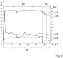
- Fig. 5 shows an exemplary diagram of a measurement protocol of a hydrogen pressure 82 in the first fluid space 36, an oxygen pressure 84 in the second fluid space 38, a flowing current 86 of the electrolysis cell 16 and an applied voltage 88 of the electrolysis cell 16 over time during an electrolysis process cycle 22.
- the diagram shows the hydrogen pressure 82 in the first fluid space 36 and the oxygen pressure 84 in the second fluid space 38 in bar over the time t.
- the diagram shows the current 86 of the electrolytic cell 16 in amperes A over time t.
- the diagram shows the voltage 88 of the electrolysis cell 16 in volts V over the time t.
- the time span shown represents an electrolysis process cycle 22 with an electrolysis process 28 and a subsequent venting of method step 68.
- the time t is listed in minutes.
Description
Die Erfindung betrifft einen Raumflugkörper mit einer Antriebsstofferzeugungsvorrichtung. Es ist bereits eine Antriebsstofferzeugungsvorrichtung für einen Raumflugkörper vorgeschlagen worden. Aus der
Die Aufgabe der Erfindung besteht insbesondere darin, eine gattungsgemäße Vorrichtung mit verbesserten Eigenschaften hinsichtlich einer einfachen und schnellen Vor-Ort-Erzeugung von Antriebsstoff für einen Raumflugkörper bereitzustellen. Die Aufgabe wird erfindungsgemäß durch die Merkmale des Patentanspruchs 1 gelöst, während vorteilhafte Ausgestaltungen und Weiterbildungen der Erfindung den Unteransprüchen entnommen werden können.The object of the invention is in particular to provide a generic device with improved properties with regard to a simple and rapid on-site generation of propellant for a spacecraft. The object is achieved according to the invention by the features of claim 1, while advantageous configurations and developments of the invention can be found in the subclaims.
Die Erfindung schlägt einen Raumflugkörper, insbesondere einen Satelliten, mit einer Antriebsstofferzeugungsvorrichtung vor, mit zumindest einem Elektrolyseur, welcher zu einer wiederkehrenden Erzeugung von Wasserstoff und Sauerstoff vorgesehen ist und zumindest eine Elektrolysezelle aufweist, die zumindest einen alkalischen Elektrolyten umfasst. Bei dem Elektrolyseur wird unter Energieaufnahme durch einen elektrischen Strom Wasser in molekularen Sauerstoff und molekularen Wasserstoff gespalten. Unter einem "Raumflugkörper" soll in diesem Zusammenhang insbesondere ein von Menschenhand geschaffener Flugkörper für den Weltraum verstanden werden. Es sind verschiedene, einem Fachmann als sinnvoll erscheinende Raumflugkörper denkbar, wie beispielsweise Raketen, Raumsonden, Raumfähren, Raumschiffe, Raumkapseln, Raumstationen und/oder besonders bevorzugt Satelliten. Unter "periodisch" soll in diesem Zusammenhang wiederkehrend verstanden werden. Vorzugsweise kann darunter sowohl zyklisch, als auch besonders bevorzugt azyklisch wiederkehrend verstanden werden. Besonders bevorzugt soll darunter insbesondere von Zeit zu Zeit, phasenhaft wiederkehrend verstanden werden. Unter einer "Elektrolysezelle" soll in diesem Zusammenhang insbesondere eine Einheit mit zumindest zwei Elektroden verstanden werden, wovon vorzugsweise eine als eine Wasserstoffelektrode und eine als eine Sauerstoffelektrode ausgebildet ist, mit einem die zwei Elektroden verbindenden Stromkreis, mit zumindest einem zumindest zwischen den zwei Elektroden angeordneten Elektrolyt und/oder mit einer zumindest zwischen den zwei Elektroden angeordneten elektrolytgefüllten oder ionenleitenden Membran verstanden werden. Die Einheit ist zu einer Durchführung einer Redox-Reaktion vorgesehen, bei der unter Aufwendung von Energie in Form von elektrischer Leistung Wasser zu einer Erzeugung von einem erste Gas, nämlich molekularem Wasserstoff, und einem zweiten Gas, nämlich molekularem Sauerstoff gespalten wird. Unter einem "Elektrolyten" soll insbesondere ein ionenleitender Stoff, vorzugsweise in Form einer Lösung, beispielsweise einer alkalischen Lösung, verstanden werden. Ferner sind verschiedene, einem Fachmann als sinnvoll erscheinende alkalische Elektrolyten denkbar, wie beispielsweise eine Kaliumhydroxid-Lösung und/oder eine Hydrazin-Lösung. Unter "vorgesehen" soll speziell programmiert, ausgelegt und/oder ausgestattet verstanden werden. Darunter, dass ein Objekt zu einer bestimmten Funktion vorgesehen ist, soll verstanden werden, dass das Objekt diese bestimmte Funktion in zumindest einem Anwendungs- und/oder Betriebszustand erfüllt und/oder ausführt.The invention proposes a spacecraft, in particular a satellite, with a propellant generating device, with at least one electrolyzer, which is provided for the recurring generation of hydrogen and oxygen and has at least one electrolytic cell, which comprises at least one alkaline electrolyte. In the case of the electrolyser, energy is absorbed by a Electric current split water into molecular oxygen and molecular hydrogen. In this context, a “spacecraft” is to be understood as meaning, in particular, a human-made missile for space. Various spacecraft that appear sensible to a person skilled in the art are conceivable, such as rockets, space probes, space shuttles, spaceships, space capsules, space stations and / or particularly preferably satellites. In this context, “periodically” should be understood to mean recurring. It can preferably be understood to mean both cyclically and, particularly preferably, acyclically recurring. Particularly preferably, this is to be understood to mean, in particular, from time to time, recurring in phases. An "electrolysis cell" is to be understood in this context in particular as a unit with at least two electrodes, one of which is preferably designed as a hydrogen electrode and one as an oxygen electrode, with a circuit connecting the two electrodes, with at least one arranged at least between the two electrodes Electrolyte and / or with an electrolyte-filled or ion-conducting membrane arranged at least between the two electrodes. The unit is intended to carry out a redox reaction in which, using energy in the form of electrical power, water is split to generate a first gas, namely molecular hydrogen, and a second gas, namely molecular oxygen. An "electrolyte" is to be understood in particular as an ion-conducting substance, preferably in the form of a solution, for example an alkaline solution. Furthermore, various alkaline electrolytes that appear sensible to a person skilled in the art are conceivable, such as, for example, a potassium hydroxide solution and / or a hydrazine solution. “Provided” is to be understood as specifically programmed, designed and / or equipped. The fact that an object is provided for a specific function should be understood to mean that the object fulfills and / or executes this specific function in at least one application and / or operating state.
Durch die erfindungsgemäße Ausgestaltung der Antriebsstofferzeugungsvorrichtung kann insbesondere eine Vorrichtung bereitgestellt werden, mit welcher vorteilhaft einfach periodisch Wasserstoff und Sauerstoff, insbesondere unter Druck, für Antriebe, insbesondere für einen Raumflugkörper, zur Verfügung gestellt werden kann. Es werden insbesondere vorteilhaft wenig aktive Komponenten benötigt. Vorzugsweise kann dadurch insbesondere eine vorteilhaft einfache und schnelle Vor-Ort-Erzeugung von einem Antriebsstoff für einen Raumflugkörper erreicht werden. Dadurch kann insbesondere ein umweltfreundliches Antriebssystem für Raumflugkörper, als "grüne Systeme" auf Basis von Wasser bereitgestellt werden. Hierzu wird das Wasser insbesondere elektrolysiert und die Bestandteile Wasserstoff und Sauerstoff insbesondere bei erhöhtem Druck dem Antriebssystem zur Verfügung gestellt. Diese Systeme sollten klein, leicht und zuverlässig sein. Das bedeutet den Einsatz möglichst einfacher, passiver Komponenten und den Verzicht auf Sensoren, Regelkomponenten, Pumpen zu Kühlung, Kompressoren und Wasserpumpen. In der Regel wird ein solches Antriebssystem nicht häufig gebraucht, d.h. es wird über die Jahre lediglich mehrere hundert- bis mehrere tausendmal unregelmäßig wiederholt betrieben.The design of the fuel generation device according to the invention makes it possible in particular to provide a device which is advantageously simple periodically hydrogen and oxygen, in particular under pressure, can be made available for propulsion systems, in particular for a spacecraft. It is particularly advantageous if little active components are required. In this way, advantageously, in particular, advantageously simple and rapid on-site generation of a propellant for a spacecraft can be achieved. In this way, in particular, an environmentally friendly propulsion system for spacecraft, as "green systems" based on water, can be provided. For this purpose, the water is especially electrolyzed and the components hydrogen and oxygen are made available to the drive system, especially at increased pressure. These systems should be small, light, and reliable. This means using the simplest possible, passive components and doing without sensors, control components, pumps for cooling, compressors and water pumps. As a rule, such a drive system is not used very often, ie it is only operated several hundred to several thousand times at irregular intervals over the years.
Ferner wird vorgeschlagen, dass die zumindest eine Elektrolysezelle von einer Matrixzelle gebildet ist. Unter einer "Matrixzelle" soll in diesem Zusammenhang insbesondere eine Elektrolysezelle verstanden werden, bei welcher die Elektrolyten in einer Matrix, vorzugsweise in einer porösen, feinporigen Matrix, fixiert sind. Vorzugsweise ist die Matrix mit den Elektrolyten insbesondere an zumindest einer der Elektroden der Elektrolysezelle angeordnet. Dadurch kann insbesondere eine besonders vorteilhafte Elektrolysezelle bereitgestellt werden. Es kann insbesondere eine vorteilhaft passive Elektrolysezelle mit wenig aktiven Komponenten bereitgestellt werden.It is also proposed that the at least one electrolysis cell is formed by a matrix cell. In this context, a “matrix cell” is to be understood in particular as an electrolysis cell in which the electrolytes are fixed in a matrix, preferably in a porous, fine-pored matrix. The matrix with the electrolytes is preferably arranged, in particular, on at least one of the electrodes of the electrolytic cell. In this way, in particular, a particularly advantageous electrolysis cell can be provided. In particular, an advantageously passive electrolysis cell with few active components can be provided.
Der zumindest eine Elektrolyseur weist zumindest ein Wasserreservoir auf, welcher zu einer Zwischenspeicherung von Wasser für einen Elektrolyseprozesszyklus vorgesehen ist. Vorzugsweise weist die Elektrolysezelle das zumindest eine Wasserreservoir auf. Das zumindest eine Wasserreservoir ist zu einer Zwischenspeicherung genau der Menge an Wasser vorgesehen, wie sie für einen Elektrolyseprozesszyklus benötigt wird. Vorzugsweise fasst das Wasserreservoir weniger als 50 g, vorzugsweise weniger als 30 g und besonders bevorzugt weniger als 10 g Wasser. Unter einem "Wasserreservoir" soll in diesem Zusammenhang insbesondere eine Einheit zur Bevorratung, insbesondere zur Zwischenspeicherung, von Wasser verstanden werden. Es sind verschiedene, einem Fachmann als sinnvoll erscheinende Reservoirs denkbar, wie beispielsweise Behälter, Tanks und/oder Speicher. Dadurch kann insbesondere eine direkte Bereitstellung von Wasser für die Elektrolyse erreicht werden. Es kann insbesondere eine definierte Menge an Wasser für die Elektrolyse bereitgestellt werden.The at least one electrolyser has at least one water reservoir which is provided for the intermediate storage of water for an electrolysis process cycle. The electrolysis cell preferably has the at least one water reservoir. The at least one water reservoir is provided for intermediate storage of precisely the amount of water that is required for an electrolysis process cycle. The water reservoir preferably holds less than 50 g, preferably less than 30 g and particularly preferably less than 10 g of water. In this context, a “water reservoir” is to be understood as meaning, in particular, a unit for supplying, in particular for temporarily storing, water. Various reservoirs that appear useful to a person skilled in the art are conceivable, such as, for example, containers, Tanks and / or storage. In this way, in particular, a direct provision of water for the electrolysis can be achieved. In particular, a defined amount of water can be provided for the electrolysis.
Die Antriebstofferzeugungsvorrichtung weist zumindest ein erstes Druckausgleichsventil auf, welches über eine Leitung mit dem Wasserreservoir und mit einer Wasserstoffleitung verbunden ist und zu einem Druckausgleich zwischen Wasser und Wasserstoff vorgesehen ist. Vorzugsweise ist das Druckausgleichsventil dazu vorgesehen, einen Druck zwischen dem Wasserreservoir und der Wasserstoffleitung auszugleichen. Dadurch kann insbesondere zuverlässig ein Druck des Wassers in dem Wasserreservoir und/oder des Wasserstoffs in der Wasserstoffleitung eingestellt werden. Vorzugsweise kann ein Druck des Wassers in dem Wasserreservoir und/oder des Wasserstoffs in der Wasserstoffleitung vorteilhaft passiv eingestellt werden. Es kann eine zuverlässige Einstellung eines Drucks erreicht werden.The fuel generating device has at least one first pressure equalization valve which is connected to the water reservoir and to a hydrogen line via a line and is provided for pressure equalization between water and hydrogen. The pressure equalization valve is preferably provided to equalize a pressure between the water reservoir and the hydrogen line. As a result, a pressure of the water in the water reservoir and / or of the hydrogen in the hydrogen line can be set in a particularly reliable manner. Preferably, a pressure of the water in the water reservoir and / or of the hydrogen in the hydrogen line can advantageously be set passively. Reliable adjustment of a pressure can be achieved.
Die Antriebsstofferzeugungsvorrichtung weist zumindest einen ersten Speichertanks zu einer Speicherung eines erzeugten Wasserstoffs und zumindest eines zweiten Speichertanks zu einer Speicherung eines erzeugten Sauerstoffs auf. Vorzugsweise können die produzierten Gase bei Bedarf für Schubdüsen des Raumflugkörpers aus den Speichertanks entnommen werden. Dadurch kann eine vorteilhafte Aufbewahrung der Gase erreicht werden. Es kann insbesondere eine langfristige Bereitstellung der Gase erreicht werden.The fuel generation device has at least one first storage tank for storing a generated hydrogen and at least one second storage tank for storing a generated oxygen. The gases produced can preferably be taken from the storage tanks for thrusters of the spacecraft if required. This enables advantageous storage of the gases to be achieved. In particular, a long-term supply of the gases can be achieved.
Ferner geht die Erfindung aus von einem Verfahren zu einem Betrieb der Antriebsstofferzeugungsvorrichtung. Vorzugsweise wird vorgeschlagen, dass zu Beginn eines Elektrolyseprozesszyklus eine definierte Menge an Wasser in ein Wasserreservoir eines Elektrolyseurs der Antriebsstofferzeugungsvorrichtung eingebracht wird. Unter einem "Elektrolyseprozesszyklus" soll in diesem Zusammenhang insbesondere ein definierter Prozesszyklus des Elektrolyseurs verstanden werden, in welchem der Elektrolyseur Wasserstoff und Sauerstoff erzeugt. Vorzugsweise soll darunter insbesondere ein definierter, periodisch durchgeführter Betriebszyklus verstanden werden. Besonders bevorzugt dauert der Elektrolyseprozesszyklus eine definierte Zeit an. Dadurch kann insbesondere vorteilhaft definiert, periodisch eine definierte Menge Wasserstoff und Sauerstoff, insbesondere unter Druck, für Antriebe, insbesondere für den Raumflugkörper, zur Verfügung gestellt werden.The invention is also based on a method for operating the fuel generating device. It is preferably proposed that, at the beginning of an electrolysis process cycle, a defined amount of water is introduced into a water reservoir of an electrolyzer of the fuel generation device. In this context, an “electrolysis process cycle” is to be understood in particular as a defined process cycle of the electrolyzer in which the electrolyzer generates hydrogen and oxygen. Preferably, this should be understood to mean, in particular, a defined, periodically performed operating cycle. The electrolysis process cycle particularly preferably lasts for a defined time. As a result, a defined amount of hydrogen and oxygen, in particular under pressure, can be made available periodically, particularly advantageously in a defined manner, for drives, in particular for the spacecraft.
Des Weiteren wird vorgeschlagen, dass das Wasser aus dem Wasserreservoir des Elektrolyseurs bei niedrigem Druck der Elektrolysezelle zugeführt wird. Unter "niedrigem Druck" soll in diesem Zusammenhang insbesondere ein Druck verstanden werden, welcher zumindest annähernd einem Umgebungsdruck entspricht. Bevorzugt beträgt eine Abweichung des Drucks von dem Umgebungsdruck maximal 2 bar, vorzugsweise maximal 1,5 bar und besonders bevorzugt maximal 1 bar. Vorzugsweise soll darunter insbesondere ein Druck mit einem absoluten Druck von maximal 2 bar, vorzugsweise maximal 1,5 bar und besonders bevorzugt maximal 1 bar verstanden werden. Hierdurch kann vorteilhaft einfach mit einem geringen Energiebedarf ein Zuführen des Wassers erreicht werden. Ist der Druck in der Elektrolysezelle gering, also nahe einem Umgebungsdruck, kann das Wasser insbesondere lediglich mit einem geringen Überdruck der Elektrolysezelle zugeführt werden.It is also proposed that the water from the water reservoir of the electrolyser be fed to the electrolysis cell at low pressure. In this context, “low pressure” is to be understood as meaning, in particular, a pressure which at least approximately corresponds to an ambient pressure. A deviation of the pressure from the ambient pressure is preferably a maximum of 2 bar, preferably a maximum of 1.5 bar and particularly preferably a maximum of 1 bar. Preferably, this should be understood to mean, in particular, a pressure with an absolute pressure of a maximum of 2 bar, preferably a maximum of 1.5 bar and particularly preferably a maximum of 1 bar. In this way, the water can advantageously be supplied in a simple manner with a low energy requirement. If the pressure in the electrolytic cell is low, that is to say close to ambient pressure, the water can in particular only be fed to the electrolytic cell with a slight excess pressure.
Es wird ferner vorgeschlagen, dass ein Elektrolyseprozess des Elektrolyseprozesszyklus selbsttätig beendet wird, wenn das Wasser in das Wasserreservoir des Elektrolyseurs aufgebracht ist. Dadurch kann insbesondere vorteilhaft definiert, periodisch eine definierte Menge Wasserstoff und Sauerstoff, insbesondere unter Druck für Antriebe, insbesondere für den Raumflugkörper, zur Verfügung gestellt werden. Dadurch kann vorteilhaft einfach ein definierter Elektrolyseprozesszyklus bereitgestellt werden. Vorzugsweise kann insbesondere vorteilhaft sicher eine selbsttätige Beendigung des Elektrolyseprozesszyklus erreicht werden.It is also proposed that an electrolysis process of the electrolysis process cycle is ended automatically when the water is applied to the water reservoir of the electrolyzer. As a result, a defined amount of hydrogen and oxygen can be made available periodically, particularly advantageously in a defined manner, in particular under pressure for propulsion systems, in particular for the spacecraft. As a result, a defined electrolysis process cycle can advantageously be provided in a simple manner. An automatic termination of the electrolysis process cycle can preferably be achieved in a particularly advantageous manner.
Es wird weiter vorgeschlagen, dass während des Elektrolyseprozesszyklus Wasserstoff und Sauerstoff mit einem Druck von zumindest 30 bar erzeugt werden. Vorzugsweise wird während des Elektrolyseprozesszyklus Wasserstoff und Sauerstoff mit einem Druck von zumindest 50 bar erzeugt. Besonders bevorzugt wird während des Elektrolyseprozesszyklus Wasserstoff und Sauerstoff mit einem Druck von maximal 100 bar erzeugt. Vorzugsweise wird der Wasserstoff und der Sauerstoff ab einem definierten Druck in der Elektrolysezelle in die Speichertanks überführt. Dadurch kann insbesondere Wasserstoff und Sauerstoff mit einem vorteilhaft hohen Druck bereitgestellt werden. Vorzugsweise können die Gase insbesondere ohne eine zusätzliche, aktive Druckerhöhung gespeichert werden. Es kann insbesondere eine Anzahl aktiver Komponenten gering gehalten werden.It is further proposed that hydrogen and oxygen be generated at a pressure of at least 30 bar during the electrolysis process cycle. Preferably, hydrogen and oxygen are generated at a pressure of at least 50 bar during the electrolysis process cycle. Particularly preferably, hydrogen and oxygen are generated at a pressure of a maximum of 100 bar during the electrolysis process cycle. The hydrogen and the oxygen are preferably transferred to the storage tanks from a defined pressure in the electrolysis cell. In this way, hydrogen and oxygen in particular can be provided at an advantageously high pressure. The gases can preferably be stored in particular without an additional, active pressure increase. In particular, a number of active components can be kept low.
Ferner wird vorgeschlagen, dass die während eines Elektrolyseprozesszyklus erzeugten Gase in Speichertanks geführt werden. Vorzugsweise werden die während des Elektrolyseprozesszyklus erzeugten Gase ab einem definierten Druck in Speichertanks geführt. Bevorzugt werden die Gase insbesondere ohne eine zusätzliche, aktive Druckerhöhung in die Speichertanks geführt. Dadurch kann eine vorteilhafte Aufbewahrung der Gase erreicht werden. Es kann insbesondere eine langfristige Bereitstellung der Gase erreicht werden.It is also proposed that the gases generated during an electrolysis process cycle are conducted into storage tanks. The gases generated during the electrolysis process cycle are preferably fed into storage tanks above a defined pressure. In particular, the gases are preferably fed into the storage tanks without an additional, active pressure increase. This enables advantageous storage of the gases to be achieved. In particular, a long-term supply of the gases can be achieved.
Des Weiteren wird vorgeschlagen, dass nach einem Elektrolyseprozess eine Wasserstoffleitung des Elektrolyseurs mit einer Sauerstoffleitung des Elektrolyseurs verbunden wird, und die Restgase in eine Umgebung abgelassen werden. Vorzugsweise wird nach einem Elektrolyseprozess die Wasserstoffleitung des Elektrolyseurs mit der Sauerstoffleitung des Elektrolyseurs gekoppelt. Eine Kopplung erfolgt insbesondere zu einem Druckausgleich zwischen der Wasserstoffleitung und der Sauerstoffleitung, um die Gase, ohne dass ein Differenzdruck entsteht, abzulassen. Vorzugsweise wird die Elektrolysezelle über die Wasserstoffleitung und die Sauerstoffleitung bis maximal Umgebungsdruck entlüftet. Bevorzugt erfolgt eine Entlüftung über ein Ventil. Dadurch kann zuverlässig ein Druck in der Elektrolysezelle für einen nächsten Elektrolyseprozesszyklus abgesenkt werden. Ist der Druck in der Elektrolysezelle gering, also nahe einem Umgebungsdruck, kann das Wasser insbesondere lediglich mit einem geringen Überdruck der Elektrolysezelle zugeführt werden. Vorzugsweise kann dadurch ein Energiebedarf des Elektrolyseurs gering gehalten werden.It is also proposed that, after an electrolysis process, a hydrogen line of the electrolyzer is connected to an oxygen line of the electrolyzer, and the residual gases are discharged into an environment. After an electrolysis process, the hydrogen line of the electrolyzer is preferably coupled to the oxygen line of the electrolyzer. A coupling takes place in particular for a pressure equalization between the hydrogen line and the oxygen line in order to let off the gases without creating a differential pressure. The electrolysis cell is preferably vented to a maximum of ambient pressure via the hydrogen line and the oxygen line. Ventilation preferably takes place via a valve. As a result, a pressure in the electrolysis cell can be reduced reliably for the next electrolysis process cycle. If the pressure in the electrolytic cell is low, that is to say close to ambient pressure, the water can in particular only be fed to the electrolytic cell with a slight excess pressure. In this way, an energy requirement of the electrolyzer can preferably be kept low.
Es wird ferner vorgeschlagen, dass ein Elektrolyseprozesszyklus gestartet wird, wenn genügend Energie für einen Elektrolyseprozesszyklus vorhanden ist und ausreichend Platz in den Speichertanks der Antriebsstofferzeugungsvorrichtung vorhanden ist. Vorzugsweise wird ein Elektrolyseprozesszyklus gestartet, wenn in einem Energiespeicher der Antriebsstofferzeugungsvorrichtung ein Energieschwellwert überschritten wird und ein Schwellwert eines Drucks in den Speichertanks unterschritten wird. Vorzugsweise wird der Elektrolyseprozesszyklus dabei selbsttätig gestartet. Hierdurch kann insbesondere gewährleistet werden, dass ständig ausreichend Gas in den Speichertanks vorhanden ist. Vorzugsweise kann dadurch ferner erreicht werden, dass die Gase nicht direkt produziert werden müssen, wenn Antriebsstoff benötigt wird. Es kann insbesondere eine vorteilhaft autonome Antriebsstofferzeugungsvorrichtung bereitgestellt werden.It is further proposed that an electrolysis process cycle is started when there is enough energy for an electrolysis process cycle and there is sufficient space in the storage tanks of the fuel generation device. An electrolysis process cycle is preferably started when an energy threshold value is exceeded in an energy store of the propulsion material generation device and the pressure falls below a threshold value in the storage tank. The electrolysis process cycle is preferably started automatically. This can in particular ensure that there is always sufficient gas in the storage tanks. In this way, it can preferably also be achieved that the gases do not have to be produced directly when fuel is required. It In particular, an advantageously autonomous fuel generation device can be provided.
Zudem wird vorgeschlagen, dass die Durchführung unter Bedingungen reduzierter oder erhöhter Schwerkraft erfolgt. Vorzugsweise soll dieses Verfahren im Weltraum angewandt werden, wie beispielsweise bei µg in einem Raumflugkörper, wie beispielsweise einem Raumschiff oder Satelliten, einem Prozess in einem Raumflugkörper bei Beschleunigungen von 10-6 xg bis 10 xg, auf einem Planeten, wie dem Mars, und/oder auf einem Trabanten, wie dem Mond. Die g-Werte sind dabei insbesondere auf einem Planeten und/oder einem Asteroiden oder in einem fliegenden Raumflugkörper zu verstehen. Grundsätzlich kann jedoch ein g-Wert verfahrenstechnisch drastisch erhöht werden, wie beispielsweise auf 100 xg. Beispielsweise können eine Anlage und/oder ein Reaktor einer künstlichen Prozessbeschleunigung ausgesetzt sein, welche von den angegebenen g-Werten abweicht. Unter "Bedingungen reduzierter Schwerkraft" sollen insbesondere Bedingungen verstanden werden, bei denen eine Schwerewirkung von maximal 0,9 xg, vorteilhaft von minimal bis 1 *10-3 xg, vorzugsweise von minimal bis 1*10-6 xg und besonders bevorzugt von minimal bis 1*10-8 xg, wirksam ist. Ferner sollen unter "Bedingungen erhöhter Schwerkraft" insbesondere Bedingungen verstanden werden, bei denen eine Schwerewirkung von zumindest 1,1 xg, vorzugsweise bis maximal 10 xg, wirksam ist. Die Schwerewirkung kann durch Gravitation und/oder künstlich durch eine Beschleunigung erzeugt sein. Die g-Werte können grundsätzlich verfahrenstechnisch drastisch erhöht werden. Mit "g" ist der Wert der Fallbeschleunigung auf der Erde von 9,81 m/s2 bezeichnet.It is also proposed that the implementation take place under conditions of reduced or increased gravity. This method should preferably be used in space, such as for µg in a spacecraft such as a spaceship or satellite, a process in a spacecraft at accelerations of 10 -6 xg to 10 xg, on a planet such as Mars, and / or on a satellite like the moon. The g-values are to be understood in particular on a planet and / or an asteroid or in a flying spacecraft. In principle, however, a g-value can be increased drastically in the process, for example to 100 xg. For example, a plant and / or a reactor can be exposed to an artificial process acceleration which deviates from the specified g-values. "Conditions of reduced gravity" are to be understood as meaning, in particular, conditions in which a gravity effect of a maximum of 0.9 xg, advantageously from a minimum to 1 * 10 -3 xg, preferably from a minimum to 1 * 10 -6 xg and particularly preferably from a minimum to 1 * 10 -8 xg, is effective. Furthermore, “conditions of increased gravity” are to be understood as meaning in particular conditions in which a gravity effect of at least 1.1 xg, preferably up to a maximum of 10 xg, is effective. The effect of gravity can be generated by gravity and / or artificially by acceleration. In principle, the g-values can be increased drastically in terms of process technology. The value of the gravitational acceleration on earth of 9.81 m / s 2 is designated with "g".
Die erfindungsgemäße Antriebsstofferzeugungsvorrichtung, der Raumflugkörper sowie das Verfahren sollen hierbei nicht auf die oben beschriebene Anwendung und Ausführungsform beschränkt sein. Insbesondere können die erfindungsgemäße Antriebsstofferzeugungsvorrichtung, der Raumflugkörper sowie das Verfahren zu einer Erfüllung einer hierin beschriebenen Funktionsweise eine von einer hierin genannten Anzahl von einzelnen Elementen, Bauteilen und Einheiten abweichende Anzahl aufweisen.The fuel generating device according to the invention, the spacecraft and the method are not intended to be restricted to the application and embodiment described above. In particular, the fuel generating device according to the invention, the spacecraft and the method for fulfilling a mode of operation described herein can have a number of individual elements, components and units that differs from a number mentioned herein.
Weitere Vorteile ergeben sich aus der folgenden Zeichnungsbeschreibung. In den Zeichnungen ist ein Ausführungsbeispiel der Erfindung dargestellt. Die Zeichnungen, die Beschreibung und die Ansprüche enthalten zahlreiche Merkmale in Kombination. Der Fachmann wird die Merkmale zweckmäßigerweise auch einzeln betrachten und zu sinnvollen weiteren Kombinationen zusammenfassen.Further advantages emerge from the following description of the drawings. In the drawings, an embodiment of the invention is shown. The drawings, the description and the claims contain numerous features in combination. The person skilled in the art will expediently also consider the features individually and combine them into useful further combinations.
Es zeigen:
- Fig. 1
- einen Raumflugkörper mit einer erfindungsgemäßen Antriebsstofferzeugungsvorrichtung und mit einer Antriebseinheit in einer schematischen Darstellung,
- Fig. 2
- die erfindungsgemäße Antriebsstofferzeugungsvorrichtung mit einem Elektrolyseur, welcher eine Elektrolysezelle aufweist, und mit zwei Speichertanks in einer schematischen Darstellung,
- Fig. 3
- die Elektrolysezelle des Elektrolyseurs mit einem integrierten Wasserreservoir in einer schematischen Explosionsschnittdarstellung,
- Fig. 4
- ein schematisches Ablaufdiagramm eines Verfahrens zu einem Betrieb der erfindungsgemäßen Antriebsstofferzeugungsvorrichtung und
- Fig. 5
- ein Diagramm eines Messprotokolls der Drücke, des fließenden Stroms und der anliegenden Spannung der Elektrolysezelle über die Zeit während eines Elektrolyseprozesszyklus.
- Fig. 1
- a spacecraft with a propellant generating device according to the invention and with a propulsion unit in a schematic representation,
- Fig. 2
- the fuel generating device according to the invention with an electrolyser, which has an electrolysis cell, and with two storage tanks in a schematic representation,
- Fig. 3
- the electrolysis cell of the electrolyser with an integrated water reservoir in a schematic exploded view,
- Fig. 4
- a schematic flow diagram of a method for operating the fuel generating device according to the invention and
- Fig. 5
- a diagram of a measurement protocol of the pressures, the flowing current and the applied voltage of the electrolysis cell over time during an electrolysis process cycle.
Die Antriebsstofferzeugungsvorrichtung 10 ist für den Raumflugkörper 12 vorgesehen. Die Antriebsstofferzeugungsvorrichtung 10 weist einen Elektrolyseur 14 auf. Der Elektrolyseur 14 ist zu einer periodischen Erzeugung von Wasserstoff und Sauerstoff vorgesehen. Der Elektrolyseur 14 ist zu einer wiederkehrenden Erzeugung von Wasserstoff und Sauerstoff vorgesehen. Der Elektrolyseur 14 ist dazu vorgesehen, unter Energieaufnahme durch einen elektrischen Strom Wasser in molekularen Sauerstoff und molekularen Wasserstoff zu spalten. Der Elektrolyseur 14 weist eine Elektrolysezelle 16 auf (
Die Elektrolysezelle 16 ist von einer Matrixzelle gebildet. Die Elektrolysezelle 16 bildet zwei Fluidräume 36, 38 aus. Die Elektrolysezelle 16 bildet einen Fluidraum 36 für den Wasserstoff und einen Fluidraum 38 für den Sauerstoff aus. Die zwei Fluidräume 36, 38 sind teilweise voneinander getrennt. Ferner weist die Elektrolysezelle 16 zwei Wandelemente 40, 42 auf, welche jeweils einen der Fluidräume 36, 38 nach außen hin begrenzen. Die Wandelemente 40, 42 sind dazu vorgesehen, die Fluidräume 36, 38 gegen einen Gasaustausch gegenüber einer Umgebung abzuschließen. Die Wandelemente 40, 42 sind jeweils scheibenförmig ausgebildet. Die Wandelemente 40, 42 sind jeweils von einem Flansch gebildet. Die Wandelemente 40, 42 bestehen aus einem elektrisch isolierenden Material. Grundsätzlich wäre jedoch auch eine andere, einem Fachmann als sinnvoll erscheinende Ausgestaltung der Wandelemente 40, 42 denkbar. Des Weiteren weist die Elektrolysezelle 16 einen Rahmen 44 auf. Der Rahmen 44 ist zwischen den beiden Fluidräumen 36, 38 angeordnet. Der Rahmen 44 weist ein integriertes, nicht weiter sichtbares Diaphragma aus. Das Diaphragma bildet eine Membran aus, die in axialer Richtung zwischen einem ersten Fluidraum 36 und einem zweiten Fluidraum 38 angeordnet ist. Die Membran dient zu einer Aufnahme von Elektrolyten 18. Die Elektrolysezelle 16 umfasst alkalische Elektrolyten 18. Ferner weist der Rahmen 44 integrierte Dichtungen 45 auf. Die Dichtungen 45 sind jeweils von einer erhabenen Dichtkontur gebildet, die dazu vorgesehen ist, eine Dichtwirkung bereitzustellen. Die Dichtungen 45 sind jeweils dazu vorgesehen, ein gegenüberliegendes Wandelement 40, 42 zu kontaktieren, um die Fluidräume 36, 38 abzudichten. Die Dichtungen 45 sind jeweils dazu vorgesehen, gegen die Wandelemente 40, 42 verpresst zu werden. Die Dichtungen 45 sind einstückig mit einem Rest des Rahmens 44 verbunden. Des Weiteren weist die Elektrolysezelle 16 zwei Elektroden 46, 48 auf, welche eine Kathode und eine Anode ausbilden. Die Elektroden 46, 48 sind jeweils in einem der Fluidräume 36, 38 angeordnet. Die Elektroden 46, 48 grenzen auf gegenüberliegenden Seiten an den Rahmen 44 an (
Des Weiteren sind die beiden Fluidräume 36, 38 über eine Wasserstoffleitung 30 und eine Sauerstoffleitung 32 verbindbar.Furthermore, the two
Ferner weist der Elektrolyseur 14 ein Wasserreservoir 20 auf, welches zu einer Zwischenspeicherung von Wasser für einen Elektrolyseprozesszyklus 22 vorgesehen ist. Das Wasserreservoir 20 ist zu einer Zwischenspeicherung genau der Menge an Wasser vorgesehen, wie sie für einen Elektrolyseprozesszyklus 22 benötigt wird. Das Wasserreservoir 20 fasst weniger als 50 g, vorzugsweise weniger als 30 g und besonders bevorzugt weniger als 10 g Wasser. Das Wasserreservoir 20 fasst beispielhaft 5 g Wasser. Das Wasserreservoir 20 ist in den Rahmen 44 der Elektrolysezelle 16 integriert. Das Wasserreservoir 20 ist mit dem nicht weiter sichtbaren Diaphragma des Rahmens 44 verbunden (
Des Weiteren weist die Antriebsstofferzeugungsvorrichtung 10 einen ersten Speichertank 24 zu einer Speicherung eines erzeugten Wasserstoffs und einen zweiten Speichertank 26 zu einer Speicherung eines erzeugten Sauerstoffs auf. Der erste Speichertank 24 ist über eine zweite Wasserstoffleitung 64 des Elektrolyseurs 14 mit dem ersten Fluidraum 36 der Elektrolysezelle 16 verbunden. Zwischen dem ersten Fluidraum 36 und dem ersten Speichertank 24 ist ein Überdruckventil 50 in der zweiten Wasserstoffleitung 64 angeordnet. Ferner ist der zweite Speichertank 26 über eine zweite Sauerstoffleitung 66 des Elektrolyseurs 14 mit dem zweiten Fluidraum 38 der Elektrolysezelle 16 verbunden. Zwischen dem zweiten Fluidraum 38 und dem zweiten Speichertank 26 ist ein Überdruckventil 52 in der zweiten Sauerstoffleitung 66 angeordnet (
Claims (9)
- Space flight body (12), in particular a satellite, with a drive unit (34) which is operated with hydrogen and oxygen and serves for a manoeuvring of the space flight body (12), and
with a propellant-generating device (10), with at least one electrolyser (14) which is configured for an iterative production of hydrogen and oxygen and comprises at least one electrolysis cell (16) having at least one alkaline electrolyte (18), wherein the propellant-generating device (10) comprises at least one first storage tank (24) for a storage of the produced hydrogen and at least one second storage tank (26) for a storage of the produced oxygen,
wherein if required the drive unit (34) retrieves gas for at least one jet nozzle from the two storage tanks (24, 26) via a duct,
characterised in that the at least one electrolyser (14) comprises at least one water reservoir (20), which is configured for an interim storage of water for an electrolysis process cycle (22), the water reservoir (20) being configured for an interim storage of precisely the quantity of water which is required for an electrolysis process cycle (22),
wherein the propellant-generating device (10) comprises at least one first pressure compensation valve (60) which is connected to the water reservoir (20) and to a hydrogen conduit (30) via a duct and which is configured for a pressure compensation between water and hydrogen. - Space flight body (12) according to claim 1,
characterised in that the at least one electrolysis cell (16) is realized by a matrix cell in which the electrolytes are fixated in a matrix. - Space flight body (12) according to claim 1 or 2,
characterised in that the water reservoir holds less than 30 g, in particular less than 10 g, of water. - Method for an operation of a space flight body (12) with a drive unit (34) and a propellant-generating device (10) according to one of the preceding claims, wherein in at least one method step, in particular in a method step of a periodical operation cycle, hydrogen and oxygen are produced,
characterised in that the gases produced during an electrolysis process cycle (22) are conveyed into the storage tanks (24, 26),
wherein at the start of an electrolysis process cycle (22) a defined quantity of water is introduced into a water reservoir (20) of an electrolyser (14) of the propellant-generating device (10). - Method according to claim 4,
characterised in that the water from the water reservoir (20) of the electrolyser (14) is fed to the electrolysis cell (16) under low pressure, the low pressure having an absolute pressure of maximally 2 bar. - Method according to one of claims 4 to 5,
characterised in that during the electrolysis process cycle (22) hydrogen and oxygen are produced with a pressure of at least 30 bar. - Method according to one of claims 4 to 6,
characterised in that the electrolysis process cycle (22) is started if there is a sufficient amount of energy for an electrolysis process cycle (22) and sufficient room in the storage tanks (24, 26) of the propellant-generating device (10). - Method according to one of claims 4 to 7,
characterised in that the implementation is effected under conditions of reduced or increased gravity. - Method according to one of claims 4 to 8,
characterised in that in a further method step (62) an electrolysis process (28) ends automatically when the water in the water reservoir (20) has been used up.
Priority Applications (4)
| Application Number | Priority Date | Filing Date | Title |
|---|---|---|---|
| EP17151463.1A EP3348671B1 (en) | 2017-01-13 | 2017-01-13 | Space craft having a fuel production apparatus |
| US15/869,330 US20180201394A1 (en) | 2017-01-13 | 2018-01-12 | Space flight body with a drive unit and with a fuel material generating device for a space flight body |
| JP2018003529A JP2018111493A (en) | 2017-01-13 | 2018-01-12 | Space flight body with drive unit and fuel material generating device for space flight body |
| CA2991873A CA2991873A1 (en) | 2017-01-13 | 2018-01-12 | Space flight body with a drive unit and with a fuel material generating device for a space flight body |
Applications Claiming Priority (1)
| Application Number | Priority Date | Filing Date | Title |
|---|---|---|---|
| EP17151463.1A EP3348671B1 (en) | 2017-01-13 | 2017-01-13 | Space craft having a fuel production apparatus |
Publications (2)
| Publication Number | Publication Date |
|---|---|
| EP3348671A1 EP3348671A1 (en) | 2018-07-18 |
| EP3348671B1 true EP3348671B1 (en) | 2021-04-21 |
Family
ID=57796264
Family Applications (1)
| Application Number | Title | Priority Date | Filing Date |
|---|---|---|---|
| EP17151463.1A Active EP3348671B1 (en) | 2017-01-13 | 2017-01-13 | Space craft having a fuel production apparatus |
Country Status (4)
| Country | Link |
|---|---|
| US (1) | US20180201394A1 (en) |
| EP (1) | EP3348671B1 (en) |
| JP (1) | JP2018111493A (en) |
| CA (1) | CA2991873A1 (en) |
Families Citing this family (2)
| Publication number | Priority date | Publication date | Assignee | Title |
|---|---|---|---|---|
| IT202000030011A1 (en) * | 2020-12-04 | 2022-06-04 | Miprons Srl | LOW AND HIGH THRUSH SPACE PROPULSION SYSTEM |
| EP4206076A1 (en) | 2021-12-30 | 2023-07-05 | Airbus Defence and Space Limited | A propulsion system |
Family Cites Families (9)
| Publication number | Priority date | Publication date | Assignee | Title |
|---|---|---|---|---|
| US3379634A (en) * | 1965-05-24 | 1968-04-23 | Air Force Usa | Zero gravity electrolysis apparatus |
| US3905884A (en) * | 1974-11-20 | 1975-09-16 | United Technologies Corp | Electrolysis cell system including recirculating product gas stream for cooling the cell |
| US4087976A (en) * | 1976-08-13 | 1978-05-09 | Massachusetts Institute Of Technology | Electric power plant using electrolytic cell-fuel cell combination |
| US4839247A (en) * | 1987-11-13 | 1989-06-13 | International Fuel Cells Corporation | Static regenerative fuel cell system for use in space |
| US5277994A (en) * | 1992-07-15 | 1994-01-11 | Rockwell International Corporation | Variable pressure passive regenerative fuel cell system |
| US8215342B2 (en) * | 2005-09-30 | 2012-07-10 | Societé BIC | Hydrogen supplies and related methods |
| EP2765224B1 (en) * | 2013-02-12 | 2018-04-11 | Airbus Defence and Space GmbH | Method for operating an electrolysis cell |
| EP2813600B1 (en) * | 2013-06-11 | 2018-11-28 | Airbus Defence and Space GmbH | Redox device with a pressure adapting unit |
| EP3311442A1 (en) * | 2015-06-18 | 2018-04-25 | Board of Regents, The University of Texas System | Water solvated glass/amorphous solid ionic conductors |
-
2017
- 2017-01-13 EP EP17151463.1A patent/EP3348671B1/en active Active
-
2018
- 2018-01-12 CA CA2991873A patent/CA2991873A1/en active Pending
- 2018-01-12 JP JP2018003529A patent/JP2018111493A/en active Pending
- 2018-01-12 US US15/869,330 patent/US20180201394A1/en not_active Abandoned
Non-Patent Citations (1)
| Title |
|---|
| WIM DE GROOT ET AL: "Electrolysis propulsion for spacecraft applications", 33RD JOINT PROPULSION CONFERENCE AND EXHIBIT, 6 July 1997 (1997-07-06), Reston, Virigina, XP055556467, DOI: 10.2514/6.1997-2948 * |
Also Published As
| Publication number | Publication date |
|---|---|
| CA2991873A1 (en) | 2018-07-13 |
| JP2018111493A (en) | 2018-07-19 |
| US20180201394A1 (en) | 2018-07-19 |
| EP3348671A1 (en) | 2018-07-18 |
Similar Documents
| Publication | Publication Date | Title |
|---|---|---|
| DE1248374C2 (en) | Propulsion device with a jet engine | |
| DE69803958T3 (en) | Electrostatic drive, spacecraft and method of propulsion | |
| EP3348671B1 (en) | Space craft having a fuel production apparatus | |
| EP3321501B1 (en) | System for energy storage and recovery | |
| DE102010053371B4 (en) | Electric energy supply device supplied with radiant energy and method for operating such a power supply device | |
| DE102012001384A1 (en) | Control valve for pressurized hydrogen refueling | |
| EP0718904A1 (en) | Fuel cell system | |
| WO2021164984A1 (en) | Air displacer, traction battery, production method and motor vehicle | |
| EP2056388A1 (en) | Method for avoiding gaseous contamination inclusions in at least one gas compartment of a fuel cell during standby and fuel cell with means to carry out the method | |
| DE4337581A1 (en) | System for supplying engines to a spacecraft with liquid fuel | |
| EP3549875B1 (en) | Regenerative air renewal system for a manned spacecraft | |
| EP2813600B1 (en) | Redox device with a pressure adapting unit | |
| DE102020002414A1 (en) | Electrified aircraft | |
| EP3988455B1 (en) | Rocket engine, method and spacecraft | |
| DE102014016491A1 (en) | Energy storage and recovery system | |
| EP3105368B1 (en) | Uninterruptible power supply for an electrolysis system | |
| DE3539167A1 (en) | Device for automatically filling the cells of electric batteries with water | |
| DE1175303B (en) | Alkaline accumulator in which the development of hydrogen is prevented when oxygen is consumed | |
| EP0155994B1 (en) | Gas-generating installation, especially for orbital stations and satellites | |
| DE102018133198A1 (en) | Energy system and method for pressure adjustment in an energy system | |
| DE10220850A1 (en) | Control device for an alkaline pressure electrolyzer | |
| DE102007051230B4 (en) | electrolyzer | |
| WO2019166298A1 (en) | Energy supply system for an underwater vehicle, method for operating an energy supply system, and underwater vehicle comprising such an energy supply system | |
| EP4032135B1 (en) | Hybrid cavern storage | |
| WO2020169376A1 (en) | Buoyancy modification module for a modular underwater vehicle |
Legal Events
| Date | Code | Title | Description |
|---|---|---|---|
| PUAI | Public reference made under article 153(3) epc to a published international application that has entered the european phase |
Free format text: ORIGINAL CODE: 0009012 |
|
| STAA | Information on the status of an ep patent application or granted ep patent |
Free format text: STATUS: THE APPLICATION HAS BEEN PUBLISHED |
|
| AK | Designated contracting states |
Kind code of ref document: A1 Designated state(s): AL AT BE BG CH CY CZ DE DK EE ES FI FR GB GR HR HU IE IS IT LI LT LU LV MC MK MT NL NO PL PT RO RS SE SI SK SM TR |
|
| AX | Request for extension of the european patent |
Extension state: BA ME |
|
| STAA | Information on the status of an ep patent application or granted ep patent |
Free format text: STATUS: REQUEST FOR EXAMINATION WAS MADE |
|
| STAA | Information on the status of an ep patent application or granted ep patent |
Free format text: STATUS: EXAMINATION IS IN PROGRESS |
|
| 17P | Request for examination filed |
Effective date: 20190118 |
|
| RBV | Designated contracting states (corrected) |
Designated state(s): AL AT BE BG CH CY CZ DE DK EE ES FI FR GB GR HR HU IE IS IT LI LT LU LV MC MK MT NL NO PL PT RO RS SE SI SK SM TR |
|
| 17Q | First examination report despatched |
Effective date: 20190220 |
|
| GRAP | Despatch of communication of intention to grant a patent |
Free format text: ORIGINAL CODE: EPIDOSNIGR1 |
|
| STAA | Information on the status of an ep patent application or granted ep patent |
Free format text: STATUS: GRANT OF PATENT IS INTENDED |
|
| INTG | Intention to grant announced |
Effective date: 20201110 |
|
| GRAS | Grant fee paid |
Free format text: ORIGINAL CODE: EPIDOSNIGR3 |
|
| GRAA | (expected) grant |
Free format text: ORIGINAL CODE: 0009210 |
|
| STAA | Information on the status of an ep patent application or granted ep patent |
Free format text: STATUS: THE PATENT HAS BEEN GRANTED |
|
| AK | Designated contracting states |
Kind code of ref document: B1 Designated state(s): AL AT BE BG CH CY CZ DE DK EE ES FI FR GB GR HR HU IE IS IT LI LT LU LV MC MK MT NL NO PL PT RO RS SE SI SK SM TR |
|
| REG | Reference to a national code |
Ref country code: GB Ref legal event code: FG4D Free format text: NOT ENGLISH |
|
| REG | Reference to a national code |
Ref country code: CH Ref legal event code: EP |
|
| REG | Reference to a national code |
Ref country code: DE Ref legal event code: R096 Ref document number: 502017010114 Country of ref document: DE Ref country code: IE Ref legal event code: FG4D Free format text: LANGUAGE OF EP DOCUMENT: GERMAN |
|
| REG | Reference to a national code |
Ref country code: AT Ref legal event code: REF Ref document number: 1384734 Country of ref document: AT Kind code of ref document: T Effective date: 20210515 |
|
| REG | Reference to a national code |
Ref country code: LT Ref legal event code: MG9D |
|
| REG | Reference to a national code |
Ref country code: NL Ref legal event code: MP Effective date: 20210421 |
|
| PG25 | Lapsed in a contracting state [announced via postgrant information from national office to epo] |
Ref country code: FI Free format text: LAPSE BECAUSE OF FAILURE TO SUBMIT A TRANSLATION OF THE DESCRIPTION OR TO PAY THE FEE WITHIN THE PRESCRIBED TIME-LIMIT Effective date: 20210421 Ref country code: LT Free format text: LAPSE BECAUSE OF FAILURE TO SUBMIT A TRANSLATION OF THE DESCRIPTION OR TO PAY THE FEE WITHIN THE PRESCRIBED TIME-LIMIT Effective date: 20210421 Ref country code: NL Free format text: LAPSE BECAUSE OF FAILURE TO SUBMIT A TRANSLATION OF THE DESCRIPTION OR TO PAY THE FEE WITHIN THE PRESCRIBED TIME-LIMIT Effective date: 20210421 Ref country code: HR Free format text: LAPSE BECAUSE OF FAILURE TO SUBMIT A TRANSLATION OF THE DESCRIPTION OR TO PAY THE FEE WITHIN THE PRESCRIBED TIME-LIMIT Effective date: 20210421 Ref country code: BG Free format text: LAPSE BECAUSE OF FAILURE TO SUBMIT A TRANSLATION OF THE DESCRIPTION OR TO PAY THE FEE WITHIN THE PRESCRIBED TIME-LIMIT Effective date: 20210721 |
|
| PG25 | Lapsed in a contracting state [announced via postgrant information from national office to epo] |
Ref country code: GR Free format text: LAPSE BECAUSE OF FAILURE TO SUBMIT A TRANSLATION OF THE DESCRIPTION OR TO PAY THE FEE WITHIN THE PRESCRIBED TIME-LIMIT Effective date: 20210722 Ref country code: LV Free format text: LAPSE BECAUSE OF FAILURE TO SUBMIT A TRANSLATION OF THE DESCRIPTION OR TO PAY THE FEE WITHIN THE PRESCRIBED TIME-LIMIT Effective date: 20210421 Ref country code: IS Free format text: LAPSE BECAUSE OF FAILURE TO SUBMIT A TRANSLATION OF THE DESCRIPTION OR TO PAY THE FEE WITHIN THE PRESCRIBED TIME-LIMIT Effective date: 20210821 Ref country code: RS Free format text: LAPSE BECAUSE OF FAILURE TO SUBMIT A TRANSLATION OF THE DESCRIPTION OR TO PAY THE FEE WITHIN THE PRESCRIBED TIME-LIMIT Effective date: 20210421 Ref country code: SE Free format text: LAPSE BECAUSE OF FAILURE TO SUBMIT A TRANSLATION OF THE DESCRIPTION OR TO PAY THE FEE WITHIN THE PRESCRIBED TIME-LIMIT Effective date: 20210421 Ref country code: PL Free format text: LAPSE BECAUSE OF FAILURE TO SUBMIT A TRANSLATION OF THE DESCRIPTION OR TO PAY THE FEE WITHIN THE PRESCRIBED TIME-LIMIT Effective date: 20210421 Ref country code: PT Free format text: LAPSE BECAUSE OF FAILURE TO SUBMIT A TRANSLATION OF THE DESCRIPTION OR TO PAY THE FEE WITHIN THE PRESCRIBED TIME-LIMIT Effective date: 20210823 Ref country code: NO Free format text: LAPSE BECAUSE OF FAILURE TO SUBMIT A TRANSLATION OF THE DESCRIPTION OR TO PAY THE FEE WITHIN THE PRESCRIBED TIME-LIMIT Effective date: 20210721 |
|
| REG | Reference to a national code |
Ref country code: DE Ref legal event code: R097 Ref document number: 502017010114 Country of ref document: DE |
|
| PG25 | Lapsed in a contracting state [announced via postgrant information from national office to epo] |
Ref country code: SM Free format text: LAPSE BECAUSE OF FAILURE TO SUBMIT A TRANSLATION OF THE DESCRIPTION OR TO PAY THE FEE WITHIN THE PRESCRIBED TIME-LIMIT Effective date: 20210421 Ref country code: SK Free format text: LAPSE BECAUSE OF FAILURE TO SUBMIT A TRANSLATION OF THE DESCRIPTION OR TO PAY THE FEE WITHIN THE PRESCRIBED TIME-LIMIT Effective date: 20210421 Ref country code: ES Free format text: LAPSE BECAUSE OF FAILURE TO SUBMIT A TRANSLATION OF THE DESCRIPTION OR TO PAY THE FEE WITHIN THE PRESCRIBED TIME-LIMIT Effective date: 20210420 Ref country code: RO Free format text: LAPSE BECAUSE OF FAILURE TO SUBMIT A TRANSLATION OF THE DESCRIPTION OR TO PAY THE FEE WITHIN THE PRESCRIBED TIME-LIMIT Effective date: 20210421 Ref country code: CZ Free format text: LAPSE BECAUSE OF FAILURE TO SUBMIT A TRANSLATION OF THE DESCRIPTION OR TO PAY THE FEE WITHIN THE PRESCRIBED TIME-LIMIT Effective date: 20210421 Ref country code: DK Free format text: LAPSE BECAUSE OF FAILURE TO SUBMIT A TRANSLATION OF THE DESCRIPTION OR TO PAY THE FEE WITHIN THE PRESCRIBED TIME-LIMIT Effective date: 20210421 Ref country code: EE Free format text: LAPSE BECAUSE OF FAILURE TO SUBMIT A TRANSLATION OF THE DESCRIPTION OR TO PAY THE FEE WITHIN THE PRESCRIBED TIME-LIMIT Effective date: 20210421 |
|
| PLBE | No opposition filed within time limit |
Free format text: ORIGINAL CODE: 0009261 |
|
| STAA | Information on the status of an ep patent application or granted ep patent |
Free format text: STATUS: NO OPPOSITION FILED WITHIN TIME LIMIT |
|
| 26N | No opposition filed |
Effective date: 20220124 |
|
| PG25 | Lapsed in a contracting state [announced via postgrant information from national office to epo] |
Ref country code: IS Free format text: LAPSE BECAUSE OF FAILURE TO SUBMIT A TRANSLATION OF THE DESCRIPTION OR TO PAY THE FEE WITHIN THE PRESCRIBED TIME-LIMIT Effective date: 20210821 Ref country code: AL Free format text: LAPSE BECAUSE OF FAILURE TO SUBMIT A TRANSLATION OF THE DESCRIPTION OR TO PAY THE FEE WITHIN THE PRESCRIBED TIME-LIMIT Effective date: 20210421 |
|
| PG25 | Lapsed in a contracting state [announced via postgrant information from national office to epo] |
Ref country code: IT Free format text: LAPSE BECAUSE OF FAILURE TO SUBMIT A TRANSLATION OF THE DESCRIPTION OR TO PAY THE FEE WITHIN THE PRESCRIBED TIME-LIMIT Effective date: 20210421 |
|
| PG25 | Lapsed in a contracting state [announced via postgrant information from national office to epo] |
Ref country code: MC Free format text: LAPSE BECAUSE OF FAILURE TO SUBMIT A TRANSLATION OF THE DESCRIPTION OR TO PAY THE FEE WITHIN THE PRESCRIBED TIME-LIMIT Effective date: 20210421 |
|
| REG | Reference to a national code |
Ref country code: CH Ref legal event code: PL |
|
| GBPC | Gb: european patent ceased through non-payment of renewal fee |
Effective date: 20220113 |
|
| REG | Reference to a national code |
Ref country code: BE Ref legal event code: MM Effective date: 20220131 |
|
| PG25 | Lapsed in a contracting state [announced via postgrant information from national office to epo] |
Ref country code: LU Free format text: LAPSE BECAUSE OF NON-PAYMENT OF DUE FEES Effective date: 20220113 Ref country code: GB Free format text: LAPSE BECAUSE OF NON-PAYMENT OF DUE FEES Effective date: 20220113 |
|
| PG25 | Lapsed in a contracting state [announced via postgrant information from national office to epo] |
Ref country code: BE Free format text: LAPSE BECAUSE OF NON-PAYMENT OF DUE FEES Effective date: 20220131 |
|
| PG25 | Lapsed in a contracting state [announced via postgrant information from national office to epo] |
Ref country code: LI Free format text: LAPSE BECAUSE OF NON-PAYMENT OF DUE FEES Effective date: 20220131 Ref country code: CH Free format text: LAPSE BECAUSE OF NON-PAYMENT OF DUE FEES Effective date: 20220131 |
|
| PG25 | Lapsed in a contracting state [announced via postgrant information from national office to epo] |
Ref country code: IE Free format text: LAPSE BECAUSE OF NON-PAYMENT OF DUE FEES Effective date: 20220113 |
|
| REG | Reference to a national code |
Ref country code: AT Ref legal event code: MM01 Ref document number: 1384734 Country of ref document: AT Kind code of ref document: T Effective date: 20220113 |
|
| PG25 | Lapsed in a contracting state [announced via postgrant information from national office to epo] |
Ref country code: AT Free format text: LAPSE BECAUSE OF NON-PAYMENT OF DUE FEES Effective date: 20220113 |
|
| PGFP | Annual fee paid to national office [announced via postgrant information from national office to epo] |
Ref country code: FR Payment date: 20230124 Year of fee payment: 7 |
|
| PG25 | Lapsed in a contracting state [announced via postgrant information from national office to epo] |
Ref country code: HU Free format text: LAPSE BECAUSE OF FAILURE TO SUBMIT A TRANSLATION OF THE DESCRIPTION OR TO PAY THE FEE WITHIN THE PRESCRIBED TIME-LIMIT; INVALID AB INITIO Effective date: 20170113 |
|
| PG25 | Lapsed in a contracting state [announced via postgrant information from national office to epo] |
Ref country code: MK Free format text: LAPSE BECAUSE OF FAILURE TO SUBMIT A TRANSLATION OF THE DESCRIPTION OR TO PAY THE FEE WITHIN THE PRESCRIBED TIME-LIMIT Effective date: 20210421 Ref country code: CY Free format text: LAPSE BECAUSE OF FAILURE TO SUBMIT A TRANSLATION OF THE DESCRIPTION OR TO PAY THE FEE WITHIN THE PRESCRIBED TIME-LIMIT Effective date: 20210421 |
|
| PGFP | Annual fee paid to national office [announced via postgrant information from national office to epo] |
Ref country code: DE Payment date: 20240119 Year of fee payment: 8 |