EP3348512A1 - Passenger conveyor system and starting/stopping control method thereof - Google Patents
Passenger conveyor system and starting/stopping control method thereof Download PDFInfo
- Publication number
- EP3348512A1 EP3348512A1 EP18151299.7A EP18151299A EP3348512A1 EP 3348512 A1 EP3348512 A1 EP 3348512A1 EP 18151299 A EP18151299 A EP 18151299A EP 3348512 A1 EP3348512 A1 EP 3348512A1
- Authority
- EP
- European Patent Office
- Prior art keywords
- passenger transportation
- transportation device
- startup
- shutdown
- low
- Prior art date
- Legal status (The legal status is an assumption and is not a legal conclusion. Google has not performed a legal analysis and makes no representation as to the accuracy of the status listed.)
- Granted
Links
Images



Classifications
-
- B—PERFORMING OPERATIONS; TRANSPORTING
- B66—HOISTING; LIFTING; HAULING
- B66B—ELEVATORS; ESCALATORS OR MOVING WALKWAYS
- B66B25/00—Control of escalators or moving walkways
- B66B25/003—Methods or algorithms therefor
-
- B—PERFORMING OPERATIONS; TRANSPORTING
- B66—HOISTING; LIFTING; HAULING
- B66B—ELEVATORS; ESCALATORS OR MOVING WALKWAYS
- B66B21/00—Kinds or types of escalators or moving walkways
- B66B21/02—Escalators
-
- B—PERFORMING OPERATIONS; TRANSPORTING
- B66—HOISTING; LIFTING; HAULING
- B66B—ELEVATORS; ESCALATORS OR MOVING WALKWAYS
- B66B21/00—Kinds or types of escalators or moving walkways
- B66B21/10—Moving walkways
-
- B—PERFORMING OPERATIONS; TRANSPORTING
- B66—HOISTING; LIFTING; HAULING
- B66B—ELEVATORS; ESCALATORS OR MOVING WALKWAYS
- B66B25/00—Control of escalators or moving walkways
-
- B—PERFORMING OPERATIONS; TRANSPORTING
- B66—HOISTING; LIFTING; HAULING
- B66B—ELEVATORS; ESCALATORS OR MOVING WALKWAYS
- B66B29/00—Safety devices of escalators or moving walkways
Definitions
- the present invention relates to the field of passenger transportation devices, in particular to a passenger transportation system and a startup and shutdown control method thereof.
- passenger transportation devices are very common in daily life.
- escalators usually used between floors of commercial buildings and moving walks usually used in large airports are especially common.
- a passenger transportation system having a plurality of passenger transportation devices used in series may be set up as well.
- the present invention aims at providing a passenger transportation system with high reliability.
- the present invention further aims at providing a startup and shutdown control method for the passenger transportation system with high reliability.
- a passenger transportation system comprises: a plurality of series-connected passenger transportation devices; an electrical control system comprising a plurality of startup and shutdown circuits which are respectively used for controlling startup and shutdown of each of the passenger transportation devices; and an electrical interlocking assembly coupled between each of the startup and shutdown circuits, wherein the electrical interlocking assembly controls a startup and shutdown sequence of a low-position passenger transportation device and a high-position passenger transportation device by controlling closing and opening of each of the startup and shutdown circuits.
- a startup and shutdown control method for the passenger transportation system comprises: a start step S100, in which a downstream passenger transportation device is firstly started and then an upstream passenger transportation device is started; and a stop step S200, in which the upstream passenger transportation device is firstly stopped and then the downstream passenger transportation device is stopped.
- the passenger transportation devices comprise Escalators and Moving Walks.
- a monitoring system and a monitoring method of the passenger transportation device provided by the embodiment of the present invention is described below in detail by taking an escalator as an example.
- the monitoring system and the monitoring method with respect to the escalator in the following embodiments may also be analogically applied to moving walks, and for example, adaptive improvements which are possibly required can be known by one skilled in the art under the teaching of the embodiments of the present invention.
- a passenger transportation system in one embodiment of the present invention comprises: a plurality of series-connected passenger transportation devices; an electrical control system comprising a plurality of startup and shutdown circuits which are respectively used for controlling startup and shutdown of each of the passenger transportation devices; and an electrical interlocking assembly coupled between each of the startup and shutdown circuits, wherein the electrical interlocking assembly controls a startup and shutdown sequence of a low-position passenger transportation device and a high-position passenger transportation device by controlling closing and opening of each of the startup and shutdown circuits.
- the passenger transportation system by realizing startup and shutdown correlation between the startup and shutdown circuits of each of the passenger transportation devices by using the electrical interlocking assembly, and thereby realizing the control of the startup and shutdown sequence of the low-position passenger transportation device and the high-position passenger transportation device, safety incidents caused by an accidental situation such as other passenger transportation devices operate normally while a certain passenger transportation is stopped suddenly or an upstream passenger transportation device operates normally while a downstream passenger transportation device is stopped suddenly are avoided, and the startup and shutdown reliability of the passenger transportation systems is greatly improved.
- each of the startup and shutdown circuits 110, 210 respectively comprises a power supply branch 111, 211 with a main contactor K1.1, K2.2, an upward movement branch 112, 212, a downward movement branch 113, 213 and a changeover switch 114, 214.
- the changeover switch 114 optionally connects the power supply branch 111 with the upward movement branch 112, or connects the power supply branch 111 with the downward movement branch 113; and in regard to the high-position passenger transportation device 200, the changeover switch 214 optionally connects the power supply branch 211 with the upward movement branch 212, or connects the power supply branch 211 with the downward movement branch 213.
- each startup and shutdown circuit 110, 210 will be selected in one of upward movement and downward movement states.
- turned-on and turned-off states of the main contactors K1.1, K2.2 arranged on the power supply branches 111, 211 may also control the turning on and turning off of corresponding power supply branches 111, 211.
- the main contactor K2.2 of the high-position passenger transportation device 200 turns on the power supply branch 211 of the high-position passenger transportation device 200, and at this moment an upward movement action of the high-position passenger transportation device 200 can be directly realized.
- the main contactor K1.1 of the low-position passenger transportation device 100 turns on the power supply branch 111 of the low-position passenger transportation device 100, and at this moment a downward movement action of the low-position passenger transportation device 100 can be directly realized.
- the electrical interlocking assembly comprises a plurality of auxiliary contactors K1.2, K2.1 corresponding to the plurality of series-connected passenger transportation devices, and each auxiliary contactor K1.2, K2.1 comprises a plurality of contacts in the same turned-on or turned-off state.
- a first contact of the auxiliary contactor K2.1 of the low-position passenger transportation device 100 is connected into the downward movement branch 213 of the high-position passenger transportation device 200.
- the auxiliary contactor K2.1 of the low-position passenger transportation device 100 is controlled to open the downward movement branch 213 of the high-position passenger transportation device 200.
- the high-position passenger transportation device 200 cannot execute the downward movement action ahead of the low-position passenger transportation device 100, avoiding the situation that the low-position passenger transportation device 100 is still stopped while the high-position passenger transportation device 200 has already moved downwards, which, otherwise, would cause passengers to gather between two passenger transportation devices such that crowding or stampede happens.
- a first contact of the auxiliary contactor K1.2 of the high-position passenger transportation device 200 is connected into the upward movement branch 112 of the low-position passenger transportation device 100.
- the auxiliary contactor K1.2 of the high-position passenger transportation device 200 turns off the upward movement branch 112 of the low-position passenger transportation device 100.
- the low-position passenger transportation device 100 cannot execute the upward movement action ahead of the high-position passenger transportation device 200, avoiding the situation that the high-position passenger transportation device 200 is still stopped while the low-position passenger transportation device 100 has already moved upwards, which otherwise, would also possibly cause passengers to gather between two passenger transportation devices such that crowding or stampede happens.
- a second contact of the auxiliary contactor K1.2 of the high-position passenger transportation device 200 is connected into the power supply branch 111 of the low-position passenger transportation device 100.
- the auxiliary contactor K1.2 of the high-position passenger transportation device 200 turns off the power supply branch 111 of the low-position passenger transportation device 100, avoiding the situation that the low-position passenger transportation device 100 still moves upwards while the high-position passenger transportation device 200, which, otherwise, would possibly cause passengers to gather between two passenger transportation devices such that crowding or stampede happens.
- auxiliary contactor K2.1 of the low-position passenger transportation device 100 is connected into the power supply branch 211 of the high-position passenger transportation device 200.
- the auxiliary contactor K2.1 of the low-position passenger transportation device 100 turns off the power supply branch 211 of the high-position passenger transportation device 200, avoiding the situation that the high-position passenger transportation device 200 still moves downwards while the low-position passenger transportation device 100 is stopped, which, otherwise, would possibly cause passengers to gather between two passenger transportation devices such that crowding or stampede happens.
- the second contacts of the auxiliary contactors K1.2, K2.1 are respectively arranged in parallel with the main contactors K1.1, K2.2.
- the main contactors K1.1, K2.2 and the auxiliary contactors K1.2, K2.1 are in opposite turned-on and turned-off states.
- the main contactors K1.1, K2.2 may be a normally closed contactor and the auxiliary contactors K1.2, K2.1 may be a normally open contactor.
- the electrical control system further comprises inspection circuits 120, 220 respectively connected in parallel with the startup and shutdown circuits 110, 210, and an inspection switch is provided on the inspection circuits 120, 220.
- the inspection circuits 120, 220 are capable of directly bypassing the startup and shutdown circuits 110, 210 to realize independent control of upward movement, downward movement or stop of any one of the passenger transportation devices.
- an electrical control box 300 for accommodating the electrical control system is arranged in a joint area between the two passenger transportation devices, thereby a minimum modification to the original circuits and original arrangement can be realized and the cost can be greatly reduced.
- the startup and shutdown circuits 110, 210 in this concept may be supplied with power from the existing circuit of the passenger transportation device.
- the startup and shutdown circuits 110, 210 are supplied with power through safety chain circuits 130, 230 of the corresponding passenger transportation device.
- the electrical control system further comprises self-locking branches 115, 215 which are directly connected into the upward movement circuit and the downward movement circuit from the power supply branches 111, 211.
- the passenger transportation devices comprise escalators and/or moving walks, or other transportation tools which play the similar role of transporting passengers.
- the normally closed main contactor K2.2 corresponding to the high-position passenger transportation device 200 is in a closed state, consequently the entire startup and shutdown circuit 210 of the high-position passenger transportation device 200 is turned on and thus the upward movement executed by the high-position passenger transportation device 200 succeeds.
- the normally closed main contactor K1.1 corresponding to the low-position passenger transportation device 100 is in a closed state, consequently the entire startup and shutdown circuit 110 of the low-position passenger transportation device 100 is turned on and thus the low-position passenger transportation device 200 keeps on moving downwards.
- the present invention is described above by taking the passenger transportation system comprising two passenger transportation devices as an example, one skilled in the art should understand that the concept of the present invention is also applicable to a passenger transportation system comprising more than two passenger transportation devices.
- the low-position passenger transportation device and the high-position passenger transportation device mentioned in the foresaid embodiments are presented as relative concepts.
- the middle passenger transportation device and the lowest passenger transportation device relatively form a first pair of low-position passenger transportation device and high-position passenger transportation device; the middle passenger transportation device and the highest passenger transportation device relatively form a second pair of low-position passenger transportation device and high-position passenger transportation device; and the lowest passenger transportation device and the highest passenger transportation device relatively form a third pair of low-position passenger transportation device and high-position passenger transportation device.
- the electrical systems and hardware facilities of the three pairs of low-position passenger transportation devices and high-position passenger transportation devices respectively satisfy the limitations described in the foresaid embodiments, they are also applicable to the concept of the present invention, can bring the same or similar technical effects and have high startup and shutdown control reliability.
- one embodiment of a startup and shutdown control method is further provided herein.
- the startup and shutdown control method comprises: a start step S100, in which a downstream passenger transportation device is firstly started and then an upstream passenger transportation device is started; and a stop step S200, in which the upstream passenger transportation device is firstly stopped and then the downstream passenger transportation device is stopped. Therefore, the control of the startup and shutdown sequence of the downstream passenger transportation device and the upstream passenger transportation device is realized, avoiding dangerous situations such as starting of the upstream passenger transportation device ahead of the downstream passenger transportation device or stopping of the downstream passenger transportation device ahead of the upstream passenger transportation device, thus avoiding the situation of people crowding or stampede, which greatly improves the startup and shutdown reliability and safety of the passenger transportation system.
- step S100 further comprises: a start protection step S110, in which when the downstream passenger transportation device is stopped, the upstream passenger transportation device cannot be started.
- This safety auxiliary measure can further avoid the situation of people crowding or stampede.
- the startup and shutdown control method further comprises an inspection step S300, in which the plurality of series-connected passenger transportation devices can be started and/or stopped in any sequence.
- the plurality of passenger transportation devices can realize free control and operations without being restricted by mutual startup and shutdown states, which are more beneficial to the inspection and maintenance of the problem of each passenger transportation device, improving the inspection efficiency and reliability.
- the startup and shutdown control method further comprises: a power-on step S400, in which power is supplied to the plurality of series-connected passenger transportation devices.
- the upstream passenger transportation device and the downstream passenger transportation device mentioned in the above-mentioned control method do not specifically refer to certain passenger transportation devices, but refer to one kind of passenger transportation devices with a common relative position property.
- the upstream passenger transportation device when the passenger transportation system moves upwards, the upstream passenger transportation device is the low-position passenger transportation device 100 and the downstream passenger transportation device is the high-position passenger transportation device 200.
- the upstream passenger transportation device when the passenger transportation device moves downwards, the upstream passenger transportation device is the high-position passenger transportation device 200 and the downstream passenger transportation device is the low-position passenger transportation device 100.
Landscapes
- Escalators And Moving Walkways (AREA)
- Elevator Control (AREA)
Abstract
Description
- The present invention relates to the field of passenger transportation devices, in particular to a passenger transportation system and a startup and shutdown control method thereof.
- At present, as one type of tools for improving walking of passengers between floors or for shortening a walking distance of passengers, passenger transportation devices are very common in daily life. As one example, escalators usually used between floors of commercial buildings and moving walks usually used in large airports are especially common. Furthermore, in consideration of device arrangement space, walking distance and the like, a passenger transportation system having a plurality of passenger transportation devices used in series may be set up as well.
- In regard to such system, since the application scope and use population thereof are very wide, various problems of potential safety hazards may inevitably and easily happen during use. As one situation, when a certain passenger transportation device in this passenger transportation system is stopped suddenly due to a fault, since an upstream passenger transportation device thereof is still in a control logic of normal operation, it is very possible to cause situations such as passengers on the upstream passenger transportation device and passengers stagnated on the faulted passenger transportation device are gathered, which probably causes safety incidents such as stampede or collision, and mass casualty incidents are even possibly caused under more serious situations. How to improve the safety startup and shutdown control of the plurality of passenger transportation devices in such passenger transportation system becomes a technical problem which needs to be urgently solved in this field.
- The present invention aims at providing a passenger transportation system with high reliability.
- The present invention further aims at providing a startup and shutdown control method for the passenger transportation system with high reliability.
- In order to realize the purpose of the present invention, according to one aspect of the present invention, a passenger transportation system is provided. The passenger transportation system comprises: a plurality of series-connected passenger transportation devices; an electrical control system comprising a plurality of startup and shutdown circuits which are respectively used for controlling startup and shutdown of each of the passenger transportation devices; and an electrical interlocking assembly coupled between each of the startup and shutdown circuits, wherein the electrical interlocking assembly controls a startup and shutdown sequence of a low-position passenger transportation device and a high-position passenger transportation device by controlling closing and opening of each of the startup and shutdown circuits.
- According to another aspect of the present invention, a startup and shutdown control method for the passenger transportation system is provided. The method comprises: a start step S100, in which a downstream passenger transportation device is firstly started and then an upstream passenger transportation device is started; and a stop step S200, in which the upstream passenger transportation device is firstly stopped and then the downstream passenger transportation device is stopped.
-
-
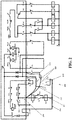
FIG. 1 is a schematic diagram of partial circuits of an electrical control system of a low-position passenger transportation device according to one embodiment of the present invention. -
FIG. 2 is a schematic diagram of partial circuits of an electrical control system of a high-position passenger transportation device according to one embodiment of the present invention. -
FIG. 3 is a schematic table of control actions and control results of each of contactors in a startup and shutdown circuit when a passenger transportation system is started according to one embodiment of the present invention. -
FIG. 4 is a schematic table of control actions and control results of each of contactors in a startup and shutdown circuit when a passenger transportation system is stopped according to one embodiment of the present invention. -
FIG. 5 is a schematic view of upward movement of a passenger transportation system according to one embodiment of the present invention. -
FIG. 6 is a schematic view of downward movement of a passenger transportation system according to one embodiment of the present invention. -
FIG. 7 is a schematic view of an arrangement position of an electrical control box according to one embodiment of the present invention. - The present invention will be more completely described with reference to the accompanying drawings, which illustrate exemplary embodiments of the present invention. However, the present invention can be implemented according to many different modes and shall be not understood as limited to the embodiments described herein. Contrarily, these embodiments are provided so that the present disclosure is thorough and complete, and to completely convey the concept of the present invention to one skilled in the art. In the drawings, the same reference signs represent the same components or parts, and thus the description thereof is omitted. Besides, some circuit diagrams illustrated in the drawings are not complete circuit diagrams for establishing the entire electrical control system of a passenger transportation device but are just illustrated parts closely related to the concept.
- In the present invention, the passenger transportation devices comprise Escalators and Moving Walks. In the embodiments illustrated below, a monitoring system and a monitoring method of the passenger transportation device provided by the embodiment of the present invention is described below in detail by taking an escalator as an example. However, it should be understood that the monitoring system and the monitoring method with respect to the escalator in the following embodiments may also be analogically applied to moving walks, and for example, adaptive improvements which are possibly required can be known by one skilled in the art under the teaching of the embodiments of the present invention.
- A passenger transportation system in one embodiment of the present invention comprises: a plurality of series-connected passenger transportation devices; an electrical control system comprising a plurality of startup and shutdown circuits which are respectively used for controlling startup and shutdown of each of the passenger transportation devices; and an electrical interlocking assembly coupled between each of the startup and shutdown circuits, wherein the electrical interlocking assembly controls a startup and shutdown sequence of a low-position passenger transportation device and a high-position passenger transportation device by controlling closing and opening of each of the startup and shutdown circuits. In the passenger transportation system according to this embodiment, by realizing startup and shutdown correlation between the startup and shutdown circuits of each of the passenger transportation devices by using the electrical interlocking assembly, and thereby realizing the control of the startup and shutdown sequence of the low-position passenger transportation device and the high-position passenger transportation device, safety incidents caused by an accidental situation such as other passenger transportation devices operate normally while a certain passenger transportation is stopped suddenly or an upstream passenger transportation device operates normally while a downstream passenger transportation device is stopped suddenly are avoided, and the startup and shutdown reliability of the passenger transportation systems is greatly improved.
- Several specific implementation modes will be listed below to specifically describe an arrangement and roles of electrical components in the startup and shutdown circuits.
- Referring to
FIG. 1 andFIG. 2 , which respectively illustrate partial startup andshutdown circuits shutdown circuits power supply branch upward movement branch downward movement branch changeover switch passenger transportation device 100, thechangeover switch 114 optionally connects thepower supply branch 111 with theupward movement branch 112, or connects thepower supply branch 111 with thedownward movement branch 113; and in regard to the high-positionpassenger transportation device 200, thechangeover switch 214 optionally connects thepower supply branch 211 with theupward movement branch 212, or connects thepower supply branch 211 with thedownward movement branch 213. In other words, when the system is automatically controlled or manually controlled by external personnel, each startup andshutdown circuit power supply branches power supply branches - Specifically, as one example of control of the main contactor, when the high-position
passenger transportation device 200 enables theupward movement branch 212, the main contactor K2.2 of the high-positionpassenger transportation device 200 turns on thepower supply branch 211 of the high-positionpassenger transportation device 200, and at this moment an upward movement action of the high-positionpassenger transportation device 200 can be directly realized. Besides, as another example of control of the main contactor, when the low-positionpassenger transportation device 100 enables thedownward movement branch 113, the main contactor K1.1 of the low-positionpassenger transportation device 100 turns on thepower supply branch 111 of the low-positionpassenger transportation device 100, and at this moment a downward movement action of the low-positionpassenger transportation device 100 can be directly realized. - Alternatively, the electrical interlocking assembly comprises a plurality of auxiliary contactors K1.2, K2.1 corresponding to the plurality of series-connected passenger transportation devices, and each auxiliary contactor K1.2, K2.1 comprises a plurality of contacts in the same turned-on or turned-off state. Herein, referring to a right side of the startup and
shutdown circuits FIG. 1 andFIG. 2 , a first contact of the auxiliary contactor K2.1 of the low-positionpassenger transportation device 100 is connected into thedownward movement branch 213 of the high-positionpassenger transportation device 200. At this moment, before the low-positionpassenger transportation device 100 enables thedownward movement branch 113, the auxiliary contactor K2.1 of the low-positionpassenger transportation device 100 is controlled to open thedownward movement branch 213 of the high-positionpassenger transportation device 200. As a result of the control, the high-positionpassenger transportation device 200 cannot execute the downward movement action ahead of the low-positionpassenger transportation device 100, avoiding the situation that the low-positionpassenger transportation device 100 is still stopped while the high-positionpassenger transportation device 200 has already moved downwards, which, otherwise, would cause passengers to gather between two passenger transportation devices such that crowding or stampede happens. - Similarly, a first contact of the auxiliary contactor K1.2 of the high-position
passenger transportation device 200 is connected into theupward movement branch 112 of the low-positionpassenger transportation device 100. At this moment, before the high-positionpassenger transportation device 200 enables theupward movement branch 212, the auxiliary contactor K1.2 of the high-positionpassenger transportation device 200 turns off theupward movement branch 112 of the low-positionpassenger transportation device 100. As a result of the control, the low-positionpassenger transportation device 100 cannot execute the upward movement action ahead of the high-positionpassenger transportation device 200, avoiding the situation that the high-positionpassenger transportation device 200 is still stopped while the low-positionpassenger transportation device 100 has already moved upwards, which otherwise, would also possibly cause passengers to gather between two passenger transportation devices such that crowding or stampede happens. - As one further improvement, referring to a left side of the startup and
shutdown circuits FIG. 1 andFIG. 2 , a second contact of the auxiliary contactor K1.2 of the high-positionpassenger transportation device 200 is connected into thepower supply branch 111 of the low-positionpassenger transportation device 100. At this moment, after the high-positionpassenger transportation device 200 disables theupward movement branch 212 due to a fault or under control, the auxiliary contactor K1.2 of the high-positionpassenger transportation device 200 turns off thepower supply branch 111 of the low-positionpassenger transportation device 100, avoiding the situation that the low-positionpassenger transportation device 100 still moves upwards while the high-positionpassenger transportation device 200, which, otherwise, would possibly cause passengers to gather between two passenger transportation devices such that crowding or stampede happens. - Similarly, a second contact of the auxiliary contactor K2.1 of the low-position
passenger transportation device 100 is connected into thepower supply branch 211 of the high-positionpassenger transportation device 200. At this moment, after the low-positionpassenger transportation device 100 disables thedownward movement branch 113 due to a fault or under control, the auxiliary contactor K2.1 of the low-positionpassenger transportation device 100 turns off thepower supply branch 211 of the high-positionpassenger transportation device 200, avoiding the situation that the high-positionpassenger transportation device 200 still moves downwards while the low-positionpassenger transportation device 100 is stopped, which, otherwise, would possibly cause passengers to gather between two passenger transportation devices such that crowding or stampede happens. - As one more specific improvement, the second contacts of the auxiliary contactors K1.2, K2.1 are respectively arranged in parallel with the main contactors K1.1, K2.2. In addition, when no power is supplied, the main contactors K1.1, K2.2 and the auxiliary contactors K1.2, K2.1 are in opposite turned-on and turned-off states. By adopting such arrangement, it guarantees that the low-position
passenger transportation device 100 can be directly started during downward movement, and whether the low-positionpassenger transportation device 100 can be started during upward movement depends on the action of the high-positionpassenger transportation device 200. Similarly, by adopting such arrangement, it also guarantees that the high-positionpassenger transportation device 200 can be directly started during upward movement, and whether the high-positionpassenger transportation device 200 can be started during downward movement depends on the action of the low-positionpassenger transportation device 100. - Alternatively, there are various implementation modes for the opposite turned-on and turned-off states of the main contactors K1.1, K2.2 and the auxiliary contactors K1.2, K2.1. As one reference implementation mode, the main contactors K1.1, K2.2 may be a normally closed contactor and the auxiliary contactors K1.2, K2.1 may be a normally open contactor.
- Besides, it should be understood that, although the description is made above by taking the contactor as an example of the electrical interlocking assembly, in fact, in order to realize an electrical interlocking function, usually an electrical component (such as a contactor), a mechanical component (such as a link rod) or a combination thereof may be adopted. Therefore, under the inspiration of the concept of the present invention, one skilled in the art may also adopt other electrical components, and make some conventional schematic modifications to the above-mentioned embodiments to realize the function of the present invention, which, however, are also included in the protective scope of the present invention.
- Alternatively, as one auxiliary improvement, the electrical control system further comprises
inspection circuits shutdown circuits inspection circuits inspection circuits shutdown circuits - Alternatively, referring to
FIG. 7 , as one reference example, when the number of the series-connected passenger transportation devices is two, anelectrical control box 300 for accommodating the electrical control system is arranged in a joint area between the two passenger transportation devices, thereby a minimum modification to the original circuits and original arrangement can be realized and the cost can be greatly reduced. - Alternatively, the startup and
shutdown circuits shutdown circuits safety chain circuits - Alternatively, as one auxiliary improvement, the electrical control system further comprises self-locking
branches power supply branches - Alternatively, the passenger transportation devices comprise escalators and/or moving walks, or other transportation tools which play the similar role of transporting passengers.
- A controlled action of each contactor in the electrical control system and a control result caused thereby will be described below in combination with the above-mentioned embodiments and
FIG. 1 to FIG. 6 . - Referring to
FIG. 1 to FIG. 3 andFIG. 5 to FIG. 6 , in a process of starting the passenger transportation system, if there is a need to realize the control of the upward movement of an escalator, at this moment, when the low-positionpassenger transportation device 100 is directly started to move upwards, since no current is supplied to the circuit of the high-positionpassenger transportation device 200, the normally open auxiliary contactor K1.2 corresponding to the high-positionpassenger transportation device 200 is in an open state at this moment, consequently theupward movement branch 112 of the startup andshutdown circuit 110 of the low-positionpassenger transportation device 100 is opened and thus the upward movement executed by the low-positionpassenger transportation device 100 fails. As another example, also in order to realize the control of upward movement of the escalator, at this moment, when the high-positionpassenger transportation device 200 is directly started to move upwards, the normally closed main contactor K2.2 corresponding to the high-positionpassenger transportation device 200 is in a closed state, consequently the entire startup andshutdown circuit 210 of the high-positionpassenger transportation device 200 is turned on and thus the upward movement executed by the high-positionpassenger transportation device 200 succeeds. - Similarly, in a process of starting the passenger transportation system, if there is a need to realize the control of the downward movement of an escalator, at this moment, when the low-position
passenger transportation device 100 is directly started to move downwards, the normally closed main contactor K1.1 corresponding to the low-positionpassenger transportation device 100 is in a closed state, consequently the entire startup andshutdown circuit 110 of the low-positionpassenger transportation device 100 is turned on and thus the downward movement executed by the low-positionpassenger transportation device 100 succeeds. As another example, also in order to realize the control of the downward movement of the escalator, at this moment, when the high-positionpassenger transportation device 200 is directly started to move downwards, since no current is supplied to the circuit of the low-positionpassenger transportation device 100, the normally open auxiliary contactor K2.1 corresponding to the low-positionpassenger transportation device 100 is in an open state, consequently thedownward movement branch 213 of the startup andshutdown circuit 210 of the high-positionpassenger transportation device 200 is opened and thus the downward movement executed by the high-positionpassenger transportation device 200 fails. - Referring to
FIG. 1 to FIG. 2 andFIG. 4 to FIG. 6 , in a process of stopping the passenger transportation system, if there is a need to realize the control of the stop of the upward movement of an escalator, at this moment, when the low-positionpassenger transportation device 100 is directly stopped from moving upwards, the normally closed main contactor K2.2 corresponding to the high-positionpassenger transportation device 200 is in a closed state, consequently the entire startup andshutdown circuit 210 of the high-positionpassenger transportation device 200 is turned on and thus the high-positionpassenger transportation device 200 keeps on moving upwards. As another example, also in order to realize the control of the stop of the upward movement of the escalator, at this moment, when the high-positionpassenger transportation device 200 is directly stopped from moving upwards, since no current is supplied to the circuit of the high-positionpassenger transportation device 200, the normally open auxiliary contactor K1.2 corresponding to the high-positionpassenger transportation device 200 is in an open state, consequently theupward movement branch 112 of the startup andshutdown circuit 110 of the low-positionpassenger transportation device 100 is opened and thus the low-positionpassenger transportation device 100 is stopped from moving upwards at the same time. - Similarly, in a process of starting the passenger transportation system, if there is a need to realize the control of the stop of the downward movement of an escalator, at this moment, when the low-position
passenger transportation device 100 is directly stopped from moving downwards, since the current supply to the circuit of the low-positionpassenger transportation device 100 is cut off, the normally open auxiliary contactor K2.1 corresponding to the low-positionpassenger transportation device 100 is in an open state, consequently thedownward movement branch 213 of the startup andshutdown circuit 210 of the high-positionpassenger transportation device 200 is opened and thus the high-positionpassenger transportation device 200 is stopped from moving downwards at the same time. As another example, also in order to realize the control of the stop of the downward movement of the escalator, at this moment, when the high-positionpassenger transportation device 200 is directly stopped from moving downwards, the normally closed main contactor K1.1 corresponding to the low-positionpassenger transportation device 100 is in a closed state, consequently the entire startup andshutdown circuit 110 of the low-positionpassenger transportation device 100 is turned on and thus the low-positionpassenger transportation device 200 keeps on moving downwards. - It should be mentioned that, although the present invention is described above by taking the passenger transportation system comprising two passenger transportation devices as an example, one skilled in the art should understand that the concept of the present invention is also applicable to a passenger transportation system comprising more than two passenger transportation devices. In regard to such system, the low-position passenger transportation device and the high-position passenger transportation device mentioned in the foresaid embodiments are presented as relative concepts. For example, in an example of a passenger transportation system comprising three series-connected passenger transportation devices, the middle passenger transportation device and the lowest passenger transportation device relatively form a first pair of low-position passenger transportation device and high-position passenger transportation device; the middle passenger transportation device and the highest passenger transportation device relatively form a second pair of low-position passenger transportation device and high-position passenger transportation device; and the lowest passenger transportation device and the highest passenger transportation device relatively form a third pair of low-position passenger transportation device and high-position passenger transportation device. At this moment, when the electrical systems and hardware facilities of the three pairs of low-position passenger transportation devices and high-position passenger transportation devices respectively satisfy the limitations described in the foresaid embodiments, they are also applicable to the concept of the present invention, can bring the same or similar technical effects and have high startup and shutdown control reliability.
- According to one aspect of the concept, in combination with the passenger transportation system described above, one embodiment of a startup and shutdown control method is further provided herein.
- The startup and shutdown control method comprises: a start step S100, in which a downstream passenger transportation device is firstly started and then an upstream passenger transportation device is started; and a stop step S200, in which the upstream passenger transportation device is firstly stopped and then the downstream passenger transportation device is stopped. Therefore, the control of the startup and shutdown sequence of the downstream passenger transportation device and the upstream passenger transportation device is realized, avoiding dangerous situations such as starting of the upstream passenger transportation device ahead of the downstream passenger transportation device or stopping of the downstream passenger transportation device ahead of the upstream passenger transportation device, thus avoiding the situation of people crowding or stampede, which greatly improves the startup and shutdown reliability and safety of the passenger transportation system.
- Alternatively, as one safety measure, step S100 further comprises: a start protection step S110, in which when the downstream passenger transportation device is stopped, the upstream passenger transportation device cannot be started. This safety auxiliary measure can further avoid the situation of people crowding or stampede.
- Alternatively, as one auxiliary measure, the startup and shutdown control method further comprises an inspection step S300, in which the plurality of series-connected passenger transportation devices can be started and/or stopped in any sequence. In this mode, the plurality of passenger transportation devices can realize free control and operations without being restricted by mutual startup and shutdown states, which are more beneficial to the inspection and maintenance of the problem of each passenger transportation device, improving the inspection efficiency and reliability.
- Alternatively, in consideration of completeness of the control method, before the system operates formally, the startup and shutdown control method further comprises: a power-on step S400, in which power is supplied to the plurality of series-connected passenger transportation devices.
- Herein, the upstream passenger transportation device and the downstream passenger transportation device mentioned in the above-mentioned control method do not specifically refer to certain passenger transportation devices, but refer to one kind of passenger transportation devices with a common relative position property. For example, as one example, when the passenger transportation system moves upwards, the upstream passenger transportation device is the low-position
passenger transportation device 100 and the downstream passenger transportation device is the high-positionpassenger transportation device 200. As another example, when the passenger transportation device moves downwards, the upstream passenger transportation device is the high-positionpassenger transportation device 200 and the downstream passenger transportation device is the low-positionpassenger transportation device 100. - The above-mentioned examples mainly describe the passenger transportation system and the startup and shutdown control method thereof provided by the present invention. Although only some implementation modes of the present invention are described, one skilled in the art should understand that the present invention may be implemented according to many other modes without departing from the essence and scope thereof. Therefore, the presented examples and implementation modes are viewed as exemplary instead of restrictive. The present invention possibly covers various modifications and replacements without departing from the spirit and scope of the present invention defined by the claims.
Claims (18)
further optionally wherein the main contactor is a normally closed contactor, and the auxiliary contactor is a normally open contactor.
Applications Claiming Priority (1)
| Application Number | Priority Date | Filing Date | Title |
|---|---|---|---|
| CN201710017522.6A CN108298417B (en) | 2017-01-11 | 2017-01-11 | Passenger transportation system and start-stop control method thereof |
Publications (2)
| Publication Number | Publication Date |
|---|---|
| EP3348512A1 true EP3348512A1 (en) | 2018-07-18 |
| EP3348512B1 EP3348512B1 (en) | 2022-04-27 |
Family
ID=60954980
Family Applications (1)
| Application Number | Title | Priority Date | Filing Date |
|---|---|---|---|
| EP18151299.7A Active EP3348512B1 (en) | 2017-01-11 | 2018-01-11 | Passenger conveyor system and starting/stopping control method thereof |
Country Status (3)
| Country | Link |
|---|---|
| US (1) | US10399824B2 (en) |
| EP (1) | EP3348512B1 (en) |
| CN (1) | CN108298417B (en) |
Families Citing this family (1)
| Publication number | Priority date | Publication date | Assignee | Title |
|---|---|---|---|---|
| JP7118261B2 (en) * | 2019-05-17 | 2022-08-15 | 三菱電機株式会社 | PASSENGER CONVEYOR BRAKE STATIC TORQUE MEASURING DEVICE AND PASSENGER CONVEYOR BRAKE STATIC TORQUE METHOD |
Citations (3)
| Publication number | Priority date | Publication date | Assignee | Title |
|---|---|---|---|---|
| JPH03288790A (en) * | 1990-04-03 | 1991-12-18 | Toshiba Corp | Controller for movable footpath |
| JP2007008657A (en) * | 2005-06-30 | 2007-01-18 | Mitsubishi Electric Corp | Escalator device |
| JP2014152036A (en) * | 2013-02-13 | 2014-08-25 | Hitachi Ltd | Conveyor device for passenger |
Family Cites Families (21)
| Publication number | Priority date | Publication date | Assignee | Title |
|---|---|---|---|---|
| DE2356497A1 (en) | 1973-11-13 | 1975-05-15 | Pohlig Heckel Bleichert | Personnel conveyor or escalator - has continuous driving chain for entire length with flights alternating with stationary platforms |
| JPH03138293A (en) | 1989-03-30 | 1991-06-12 | Mitsubishi Electric Corp | Circulating round escalator |
| JPH0331192A (en) | 1989-06-28 | 1991-02-08 | Hitachi Ltd | Evacuation structure for passenger conveyor |
| JPH0818780B2 (en) | 1989-08-25 | 1996-02-28 | 株式会社日立製作所 | Passenger conveyor |
| JPH05338977A (en) | 1992-05-14 | 1993-12-21 | Otis Elevator Co | Plural interlocked escalators |
| JPH0859162A (en) | 1994-08-24 | 1996-03-05 | Toshiba Corp | Control device for escalator with steps for wheelchair |
| JPH0873164A (en) | 1994-09-01 | 1996-03-19 | Toshiba Corp | Control device for escalator with steps for wheelchair |
| US5601178A (en) * | 1995-03-16 | 1997-02-11 | Zaharia; Vlad | Detection of escalator safety circuit component operability |
| CN1061994C (en) | 1995-07-14 | 2001-02-14 | 中国石油化工总公司 | Syndiotactic selective compound metallocene catalyst |
| JP2000109282A (en) | 1998-10-01 | 2000-04-18 | Mitsubishi Electric Building Techno Service Co Ltd | Safety device for passenger conveying device |
| JP3603690B2 (en) | 1999-09-13 | 2004-12-22 | 株式会社日立製作所 | Passenger conveyor |
| JP3612468B2 (en) | 2000-03-02 | 2005-01-19 | 株式会社日立製作所 | Stairway facility with intermediate landing |
| DE10048458B4 (en) * | 2000-09-29 | 2004-11-11 | Siemens Ag | Feeding device for conveyor belts loaded with placement elements |
| US7407048B2 (en) * | 2006-08-21 | 2008-08-05 | Kone Corporation | Safety switch and method of checked redundancy |
| CN101314450A (en) | 2007-05-29 | 2008-12-03 | 张国成 | Two-layer and more than two-layer handrail elevator |
| JP4712078B2 (en) * | 2008-08-26 | 2011-06-29 | 株式会社日立ビルシステム | Passenger conveyor |
| CN201415909Y (en) | 2009-05-04 | 2010-03-03 | 哈尔滨理工大学 | Tandem Escalator |
| US20140069771A1 (en) | 2012-09-11 | 2014-03-13 | John Richard Strieter | Duo spiral escalator with direct return |
| TWI622548B (en) * | 2012-12-13 | 2018-05-01 | 伊文修股份有限公司 | Monitoring device for a transport installation for persons, trasnport installation for persons, and method of monitoring a transport installation for persons |
| CN203064983U (en) * | 2013-02-22 | 2013-07-17 | 管小峰 | Combined escalator |
| CN204474112U (en) | 2015-02-12 | 2015-07-15 | 申龙电梯股份有限公司 | A linkage control system for multiple escalators |
-
2017
- 2017-01-11 CN CN201710017522.6A patent/CN108298417B/en active Active
-
2018
- 2018-01-10 US US15/867,349 patent/US10399824B2/en active Active
- 2018-01-11 EP EP18151299.7A patent/EP3348512B1/en active Active
Patent Citations (3)
| Publication number | Priority date | Publication date | Assignee | Title |
|---|---|---|---|---|
| JPH03288790A (en) * | 1990-04-03 | 1991-12-18 | Toshiba Corp | Controller for movable footpath |
| JP2007008657A (en) * | 2005-06-30 | 2007-01-18 | Mitsubishi Electric Corp | Escalator device |
| JP2014152036A (en) * | 2013-02-13 | 2014-08-25 | Hitachi Ltd | Conveyor device for passenger |
Also Published As
| Publication number | Publication date |
|---|---|
| US10399824B2 (en) | 2019-09-03 |
| EP3348512B1 (en) | 2022-04-27 |
| CN108298417B (en) | 2020-09-25 |
| US20180194597A1 (en) | 2018-07-12 |
| CN108298417A (en) | 2018-07-20 |
Similar Documents
| Publication | Publication Date | Title |
|---|---|---|
| EP3396811A1 (en) | Motor train unit auxiliary power supply apparatus | |
| CN104411614B (en) | Theft-resistant link chain circuit | |
| EP3348512B1 (en) | Passenger conveyor system and starting/stopping control method thereof | |
| US10035660B2 (en) | Conveyor facility having a safety function | |
| CN112456267B (en) | Electrical safety detection control circuit for elevator maintenance operation | |
| CN206126533U (en) | Maintenance loop device of elevator | |
| CN102868296A (en) | Step-down circuit for combination type direct-current power supply system | |
| KR20010043925A (en) | Device for safely disconnecting an electrical load with especially high inductivity from an electrical dc-voltage supply | |
| US6597154B2 (en) | Electrical energy distribution system and contactor for such a system | |
| US5549179A (en) | Cost effective control of the main switches of an elevator drive motor | |
| US6937450B1 (en) | Grounded isolation system | |
| CN102385335B (en) | Scraper loader early warning centralized controller | |
| US20150311830A1 (en) | Control Circuit and Electrical Device | |
| CN201797302U (en) | Protective device for lifting of heavy crown block | |
| CN105800412B (en) | A kind of elevator faults recognition control circuit and its method of work | |
| CN106159917B (en) | Power distribution network indulges the relay protection system of sequence accelerated motion | |
| CN113401169A (en) | Control method, device and system based on signal lamp control circuit | |
| CN204720972U (en) | A kind of protective device of 10kV breaker closing coil | |
| US8803369B1 (en) | Automatic isolation switch for power transfer with emergency isolation control | |
| CN208394580U (en) | A kind of carriage limiting device | |
| EP3435502B1 (en) | Electronic ciruit comprising a switching means | |
| US20180090986A1 (en) | Load management and switching devices and methods | |
| KR101669602B1 (en) | Self Test Pull Cord Switch | |
| CN206004299U (en) | The relay protection system of sequence accelerated motion indulged by power distribution network | |
| JP2000244373A (en) | Repeater and network using the same |
Legal Events
| Date | Code | Title | Description |
|---|---|---|---|
| PUAI | Public reference made under article 153(3) epc to a published international application that has entered the european phase |
Free format text: ORIGINAL CODE: 0009012 |
|
| STAA | Information on the status of an ep patent application or granted ep patent |
Free format text: STATUS: THE APPLICATION HAS BEEN PUBLISHED |
|
| AK | Designated contracting states |
Kind code of ref document: A1 Designated state(s): AL AT BE BG CH CY CZ DE DK EE ES FI FR GB GR HR HU IE IS IT LI LT LU LV MC MK MT NL NO PL PT RO RS SE SI SK SM TR |
|
| AX | Request for extension of the european patent |
Extension state: BA ME |
|
| STAA | Information on the status of an ep patent application or granted ep patent |
Free format text: STATUS: REQUEST FOR EXAMINATION WAS MADE |
|
| 17P | Request for examination filed |
Effective date: 20190118 |
|
| RBV | Designated contracting states (corrected) |
Designated state(s): AL AT BE BG CH CY CZ DE DK EE ES FI FR GB GR HR HU IE IS IT LI LT LU LV MC MK MT NL NO PL PT RO RS SE SI SK SM TR |
|
| STAA | Information on the status of an ep patent application or granted ep patent |
Free format text: STATUS: EXAMINATION IS IN PROGRESS |
|
| 17Q | First examination report despatched |
Effective date: 20200512 |
|
| GRAP | Despatch of communication of intention to grant a patent |
Free format text: ORIGINAL CODE: EPIDOSNIGR1 |
|
| STAA | Information on the status of an ep patent application or granted ep patent |
Free format text: STATUS: GRANT OF PATENT IS INTENDED |
|
| INTG | Intention to grant announced |
Effective date: 20211208 |
|
| GRAS | Grant fee paid |
Free format text: ORIGINAL CODE: EPIDOSNIGR3 |
|
| GRAA | (expected) grant |
Free format text: ORIGINAL CODE: 0009210 |
|
| STAA | Information on the status of an ep patent application or granted ep patent |
Free format text: STATUS: THE PATENT HAS BEEN GRANTED |
|
| AK | Designated contracting states |
Kind code of ref document: B1 Designated state(s): AL AT BE BG CH CY CZ DE DK EE ES FI FR GB GR HR HU IE IS IT LI LT LU LV MC MK MT NL NO PL PT RO RS SE SI SK SM TR |
|
| REG | Reference to a national code |
Ref country code: GB Ref legal event code: FG4D |
|
| REG | Reference to a national code |
Ref country code: CH Ref legal event code: EP |
|
| REG | Reference to a national code |
Ref country code: AT Ref legal event code: REF Ref document number: 1486821 Country of ref document: AT Kind code of ref document: T Effective date: 20220515 |
|
| REG | Reference to a national code |
Ref country code: DE Ref legal event code: R096 Ref document number: 602018034373 Country of ref document: DE |
|
| REG | Reference to a national code |
Ref country code: IE Ref legal event code: FG4D |
|
| REG | Reference to a national code |
Ref country code: LT Ref legal event code: MG9D |
|
| REG | Reference to a national code |
Ref country code: NL Ref legal event code: MP Effective date: 20220427 |
|
| REG | Reference to a national code |
Ref country code: AT Ref legal event code: MK05 Ref document number: 1486821 Country of ref document: AT Kind code of ref document: T Effective date: 20220427 |
|
| PG25 | Lapsed in a contracting state [announced via postgrant information from national office to epo] |
Ref country code: NL Free format text: LAPSE BECAUSE OF FAILURE TO SUBMIT A TRANSLATION OF THE DESCRIPTION OR TO PAY THE FEE WITHIN THE PRESCRIBED TIME-LIMIT Effective date: 20220427 |
|
| PG25 | Lapsed in a contracting state [announced via postgrant information from national office to epo] |
Ref country code: SE Free format text: LAPSE BECAUSE OF FAILURE TO SUBMIT A TRANSLATION OF THE DESCRIPTION OR TO PAY THE FEE WITHIN THE PRESCRIBED TIME-LIMIT Effective date: 20220427 Ref country code: PT Free format text: LAPSE BECAUSE OF FAILURE TO SUBMIT A TRANSLATION OF THE DESCRIPTION OR TO PAY THE FEE WITHIN THE PRESCRIBED TIME-LIMIT Effective date: 20220829 Ref country code: NO Free format text: LAPSE BECAUSE OF FAILURE TO SUBMIT A TRANSLATION OF THE DESCRIPTION OR TO PAY THE FEE WITHIN THE PRESCRIBED TIME-LIMIT Effective date: 20220727 Ref country code: LT Free format text: LAPSE BECAUSE OF FAILURE TO SUBMIT A TRANSLATION OF THE DESCRIPTION OR TO PAY THE FEE WITHIN THE PRESCRIBED TIME-LIMIT Effective date: 20220427 Ref country code: HR Free format text: LAPSE BECAUSE OF FAILURE TO SUBMIT A TRANSLATION OF THE DESCRIPTION OR TO PAY THE FEE WITHIN THE PRESCRIBED TIME-LIMIT Effective date: 20220427 Ref country code: GR Free format text: LAPSE BECAUSE OF FAILURE TO SUBMIT A TRANSLATION OF THE DESCRIPTION OR TO PAY THE FEE WITHIN THE PRESCRIBED TIME-LIMIT Effective date: 20220728 Ref country code: FI Free format text: LAPSE BECAUSE OF FAILURE TO SUBMIT A TRANSLATION OF THE DESCRIPTION OR TO PAY THE FEE WITHIN THE PRESCRIBED TIME-LIMIT Effective date: 20220427 Ref country code: BG Free format text: LAPSE BECAUSE OF FAILURE TO SUBMIT A TRANSLATION OF THE DESCRIPTION OR TO PAY THE FEE WITHIN THE PRESCRIBED TIME-LIMIT Effective date: 20220727 Ref country code: AT Free format text: LAPSE BECAUSE OF FAILURE TO SUBMIT A TRANSLATION OF THE DESCRIPTION OR TO PAY THE FEE WITHIN THE PRESCRIBED TIME-LIMIT Effective date: 20220427 |
|
| PG25 | Lapsed in a contracting state [announced via postgrant information from national office to epo] |
Ref country code: RS Free format text: LAPSE BECAUSE OF FAILURE TO SUBMIT A TRANSLATION OF THE DESCRIPTION OR TO PAY THE FEE WITHIN THE PRESCRIBED TIME-LIMIT Effective date: 20220427 Ref country code: PL Free format text: LAPSE BECAUSE OF FAILURE TO SUBMIT A TRANSLATION OF THE DESCRIPTION OR TO PAY THE FEE WITHIN THE PRESCRIBED TIME-LIMIT Effective date: 20220427 Ref country code: LV Free format text: LAPSE BECAUSE OF FAILURE TO SUBMIT A TRANSLATION OF THE DESCRIPTION OR TO PAY THE FEE WITHIN THE PRESCRIBED TIME-LIMIT Effective date: 20220427 Ref country code: IS Free format text: LAPSE BECAUSE OF FAILURE TO SUBMIT A TRANSLATION OF THE DESCRIPTION OR TO PAY THE FEE WITHIN THE PRESCRIBED TIME-LIMIT Effective date: 20220827 |
|
| REG | Reference to a national code |
Ref country code: DE Ref legal event code: R097 Ref document number: 602018034373 Country of ref document: DE |
|
| PG25 | Lapsed in a contracting state [announced via postgrant information from national office to epo] |
Ref country code: SM Free format text: LAPSE BECAUSE OF FAILURE TO SUBMIT A TRANSLATION OF THE DESCRIPTION OR TO PAY THE FEE WITHIN THE PRESCRIBED TIME-LIMIT Effective date: 20220427 Ref country code: SK Free format text: LAPSE BECAUSE OF FAILURE TO SUBMIT A TRANSLATION OF THE DESCRIPTION OR TO PAY THE FEE WITHIN THE PRESCRIBED TIME-LIMIT Effective date: 20220427 Ref country code: RO Free format text: LAPSE BECAUSE OF FAILURE TO SUBMIT A TRANSLATION OF THE DESCRIPTION OR TO PAY THE FEE WITHIN THE PRESCRIBED TIME-LIMIT Effective date: 20220427 Ref country code: ES Free format text: LAPSE BECAUSE OF FAILURE TO SUBMIT A TRANSLATION OF THE DESCRIPTION OR TO PAY THE FEE WITHIN THE PRESCRIBED TIME-LIMIT Effective date: 20220427 Ref country code: EE Free format text: LAPSE BECAUSE OF FAILURE TO SUBMIT A TRANSLATION OF THE DESCRIPTION OR TO PAY THE FEE WITHIN THE PRESCRIBED TIME-LIMIT Effective date: 20220427 Ref country code: DK Free format text: LAPSE BECAUSE OF FAILURE TO SUBMIT A TRANSLATION OF THE DESCRIPTION OR TO PAY THE FEE WITHIN THE PRESCRIBED TIME-LIMIT Effective date: 20220427 Ref country code: CZ Free format text: LAPSE BECAUSE OF FAILURE TO SUBMIT A TRANSLATION OF THE DESCRIPTION OR TO PAY THE FEE WITHIN THE PRESCRIBED TIME-LIMIT Effective date: 20220427 |
|
| PLBE | No opposition filed within time limit |
Free format text: ORIGINAL CODE: 0009261 |
|
| STAA | Information on the status of an ep patent application or granted ep patent |
Free format text: STATUS: NO OPPOSITION FILED WITHIN TIME LIMIT |
|
| PG25 | Lapsed in a contracting state [announced via postgrant information from national office to epo] |
Ref country code: AL Free format text: LAPSE BECAUSE OF FAILURE TO SUBMIT A TRANSLATION OF THE DESCRIPTION OR TO PAY THE FEE WITHIN THE PRESCRIBED TIME-LIMIT Effective date: 20220427 |
|
| 26N | No opposition filed |
Effective date: 20230130 |
|
| PG25 | Lapsed in a contracting state [announced via postgrant information from national office to epo] |
Ref country code: SI Free format text: LAPSE BECAUSE OF FAILURE TO SUBMIT A TRANSLATION OF THE DESCRIPTION OR TO PAY THE FEE WITHIN THE PRESCRIBED TIME-LIMIT Effective date: 20220427 |
|
| REG | Reference to a national code |
Ref country code: DE Ref legal event code: R119 Ref document number: 602018034373 Country of ref document: DE |
|
| REG | Reference to a national code |
Ref country code: CH Ref legal event code: PL |
|
| PG25 | Lapsed in a contracting state [announced via postgrant information from national office to epo] |
Ref country code: LU Free format text: LAPSE BECAUSE OF NON-PAYMENT OF DUE FEES Effective date: 20230111 |
|
| REG | Reference to a national code |
Ref country code: BE Ref legal event code: MM Effective date: 20230131 |
|
| PG25 | Lapsed in a contracting state [announced via postgrant information from national office to epo] |
Ref country code: LI Free format text: LAPSE BECAUSE OF NON-PAYMENT OF DUE FEES Effective date: 20230131 Ref country code: DE Free format text: LAPSE BECAUSE OF NON-PAYMENT OF DUE FEES Effective date: 20230801 Ref country code: CH Free format text: LAPSE BECAUSE OF NON-PAYMENT OF DUE FEES Effective date: 20230131 |
|
| PG25 | Lapsed in a contracting state [announced via postgrant information from national office to epo] |
Ref country code: BE Free format text: LAPSE BECAUSE OF NON-PAYMENT OF DUE FEES Effective date: 20230131 |
|
| PG25 | Lapsed in a contracting state [announced via postgrant information from national office to epo] |
Ref country code: IT Free format text: LAPSE BECAUSE OF FAILURE TO SUBMIT A TRANSLATION OF THE DESCRIPTION OR TO PAY THE FEE WITHIN THE PRESCRIBED TIME-LIMIT Effective date: 20220427 Ref country code: IE Free format text: LAPSE BECAUSE OF NON-PAYMENT OF DUE FEES Effective date: 20230111 |
|
| PG25 | Lapsed in a contracting state [announced via postgrant information from national office to epo] |
Ref country code: MC Free format text: LAPSE BECAUSE OF FAILURE TO SUBMIT A TRANSLATION OF THE DESCRIPTION OR TO PAY THE FEE WITHIN THE PRESCRIBED TIME-LIMIT Effective date: 20220427 |
|
| PG25 | Lapsed in a contracting state [announced via postgrant information from national office to epo] |
Ref country code: MC Free format text: LAPSE BECAUSE OF FAILURE TO SUBMIT A TRANSLATION OF THE DESCRIPTION OR TO PAY THE FEE WITHIN THE PRESCRIBED TIME-LIMIT Effective date: 20220427 |
|
| PG25 | Lapsed in a contracting state [announced via postgrant information from national office to epo] |
Ref country code: BG Free format text: LAPSE BECAUSE OF FAILURE TO SUBMIT A TRANSLATION OF THE DESCRIPTION OR TO PAY THE FEE WITHIN THE PRESCRIBED TIME-LIMIT Effective date: 20220427 |
|
| PG25 | Lapsed in a contracting state [announced via postgrant information from national office to epo] |
Ref country code: BG Free format text: LAPSE BECAUSE OF FAILURE TO SUBMIT A TRANSLATION OF THE DESCRIPTION OR TO PAY THE FEE WITHIN THE PRESCRIBED TIME-LIMIT Effective date: 20220427 |
|
| PG25 | Lapsed in a contracting state [announced via postgrant information from national office to epo] |
Ref country code: CY Free format text: LAPSE BECAUSE OF FAILURE TO SUBMIT A TRANSLATION OF THE DESCRIPTION OR TO PAY THE FEE WITHIN THE PRESCRIBED TIME-LIMIT; INVALID AB INITIO Effective date: 20180111 |
|
| PG25 | Lapsed in a contracting state [announced via postgrant information from national office to epo] |
Ref country code: HU Free format text: LAPSE BECAUSE OF FAILURE TO SUBMIT A TRANSLATION OF THE DESCRIPTION OR TO PAY THE FEE WITHIN THE PRESCRIBED TIME-LIMIT; INVALID AB INITIO Effective date: 20180111 |
|
| PG25 | Lapsed in a contracting state [announced via postgrant information from national office to epo] |
Ref country code: TR Free format text: LAPSE BECAUSE OF FAILURE TO SUBMIT A TRANSLATION OF THE DESCRIPTION OR TO PAY THE FEE WITHIN THE PRESCRIBED TIME-LIMIT Effective date: 20220427 |
|
| PGFP | Annual fee paid to national office [announced via postgrant information from national office to epo] |
Ref country code: GB Payment date: 20251217 Year of fee payment: 9 |
|
| PGFP | Annual fee paid to national office [announced via postgrant information from national office to epo] |
Ref country code: FR Payment date: 20251217 Year of fee payment: 9 |