EP3348508A1 - An arrangement and method for detecting at least one operational parameter of an automatic door - Google Patents
An arrangement and method for detecting at least one operational parameter of an automatic door Download PDFInfo
- Publication number
- EP3348508A1 EP3348508A1 EP17151782.4A EP17151782A EP3348508A1 EP 3348508 A1 EP3348508 A1 EP 3348508A1 EP 17151782 A EP17151782 A EP 17151782A EP 3348508 A1 EP3348508 A1 EP 3348508A1
- Authority
- EP
- European Patent Office
- Prior art keywords
- door
- magnetometer
- arrangement
- detected data
- magnetic field
- Prior art date
- Legal status (The legal status is an assumption and is not a legal conclusion. Google has not performed a legal analysis and makes no representation as to the accuracy of the status listed.)
- Granted
Links
- 238000000034 method Methods 0.000 title claims abstract description 25
- 238000001514 detection method Methods 0.000 claims description 10
- 230000004907 flux Effects 0.000 claims description 6
- 230000004044 response Effects 0.000 claims description 6
- 238000004891 communication Methods 0.000 description 13
- 230000015654 memory Effects 0.000 description 9
- 239000002184 metal Substances 0.000 description 6
- 238000004590 computer program Methods 0.000 description 3
- 238000005516 engineering process Methods 0.000 description 3
- 238000009434 installation Methods 0.000 description 3
- 230000008859 change Effects 0.000 description 2
- 230000003068 static effect Effects 0.000 description 2
- 230000009471 action Effects 0.000 description 1
- 230000015572 biosynthetic process Effects 0.000 description 1
- 238000010276 construction Methods 0.000 description 1
- 230000006870 function Effects 0.000 description 1
Images


Classifications
-
- B—PERFORMING OPERATIONS; TRANSPORTING
- B66—HOISTING; LIFTING; HAULING
- B66B—ELEVATORS; ESCALATORS OR MOVING WALKWAYS
- B66B5/00—Applications of checking, fault-correcting, or safety devices in elevators
- B66B5/0006—Monitoring devices or performance analysers
- B66B5/0018—Devices monitoring the operating condition of the elevator system
- B66B5/0025—Devices monitoring the operating condition of the elevator system for maintenance or repair
-
- B—PERFORMING OPERATIONS; TRANSPORTING
- B66—HOISTING; LIFTING; HAULING
- B66B—ELEVATORS; ESCALATORS OR MOVING WALKWAYS
- B66B13/00—Doors, gates, or other apparatus controlling access to, or exit from, cages or lift well landings
- B66B13/02—Door or gate operation
- B66B13/14—Control systems or devices
- B66B13/143—Control systems or devices electrical
- B66B13/146—Control systems or devices electrical method or algorithm for controlling doors
-
- B—PERFORMING OPERATIONS; TRANSPORTING
- B66—HOISTING; LIFTING; HAULING
- B66B—ELEVATORS; ESCALATORS OR MOVING WALKWAYS
- B66B13/00—Doors, gates, or other apparatus controlling access to, or exit from, cages or lift well landings
- B66B13/22—Operation of door or gate contacts
-
- B—PERFORMING OPERATIONS; TRANSPORTING
- B66—HOISTING; LIFTING; HAULING
- B66B—ELEVATORS; ESCALATORS OR MOVING WALKWAYS
- B66B5/00—Applications of checking, fault-correcting, or safety devices in elevators
- B66B5/0006—Monitoring devices or performance analysers
- B66B5/0018—Devices monitoring the operating condition of the elevator system
-
- E—FIXED CONSTRUCTIONS
- E05—LOCKS; KEYS; WINDOW OR DOOR FITTINGS; SAFES
- E05F—DEVICES FOR MOVING WINGS INTO OPEN OR CLOSED POSITION; CHECKS FOR WINGS; WING FITTINGS NOT OTHERWISE PROVIDED FOR, CONCERNED WITH THE FUNCTIONING OF THE WING
- E05F15/00—Power-operated mechanisms for wings
- E05F15/40—Safety devices, e.g. detection of obstructions or end positions
-
- G—PHYSICS
- G01—MEASURING; TESTING
- G01R—MEASURING ELECTRIC VARIABLES; MEASURING MAGNETIC VARIABLES
- G01R33/00—Arrangements or instruments for measuring magnetic variables
- G01R33/02—Measuring direction or magnitude of magnetic fields or magnetic flux
-
- B—PERFORMING OPERATIONS; TRANSPORTING
- B66—HOISTING; LIFTING; HAULING
- B66B—ELEVATORS; ESCALATORS OR MOVING WALKWAYS
- B66B5/00—Applications of checking, fault-correcting, or safety devices in elevators
- B66B5/0043—Devices enhancing safety during maintenance
- B66B5/005—Safety of maintenance personnel
-
- E—FIXED CONSTRUCTIONS
- E05—LOCKS; KEYS; WINDOW OR DOOR FITTINGS; SAFES
- E05F—DEVICES FOR MOVING WINGS INTO OPEN OR CLOSED POSITION; CHECKS FOR WINGS; WING FITTINGS NOT OTHERWISE PROVIDED FOR, CONCERNED WITH THE FUNCTIONING OF THE WING
- E05F15/00—Power-operated mechanisms for wings
- E05F15/60—Power-operated mechanisms for wings using electrical actuators
- E05F15/603—Power-operated mechanisms for wings using electrical actuators using rotary electromotors
- E05F15/632—Power-operated mechanisms for wings using electrical actuators using rotary electromotors for horizontally-sliding wings
- E05F15/643—Power-operated mechanisms for wings using electrical actuators using rotary electromotors for horizontally-sliding wings operated by flexible elongated pulling elements, e.g. belts, chains or cables
- E05F15/646—Power-operated mechanisms for wings using electrical actuators using rotary electromotors for horizontally-sliding wings operated by flexible elongated pulling elements, e.g. belts, chains or cables allowing or involving a secondary movement of the wing, e.g. rotational or transversal
Definitions
- the invention concerns in general the technical field of an automatic door technology. Especially the invention concerns observation of an operation of the automatic door.
- Automatic doors are used in a variety of environments, such as in elevators and in buildings.
- the automatic doors refer to door solutions in which the door is configured to be operated without specific action by a user of a door.
- Information about the at least one operational parameter of an automatic door is important for many reasons, for example for safety reasons.
- the at least one operational parameter of the automatic door may be at least state information or position information.
- the state information of the door gives advantageous information about the operation of the door. Different door states may be open, closed, or moving. For example, if the door is detected to perform multiple subsequent closing-opening cycles, it may indicate some failure in the operation of the door. Thus, it may be useful to observe the at least one operational information of the door.
- the at least one operational parameter of the door may be obtained substantially accurately from the control system of the door.
- at least one operational parameter of the door may be obtained from the elevator control system.
- the access to the control system of the door is blocked or some other way unreachable for example due to unknown interface or protocol, the at least one operational parameter of the door cannot be obtained from the control system of the door. In that case other solutions for obtaining the at least one operational parameter of the door need to be found.
- the operational parameter of the door such as state or position, in the elevator environment may be obtained by means of a camera, such as a still camera or a video camera. Furthermore, the operational parameter of the door may be ascertained by means of a magnetometer attached to the elevator car.
- the magnetometer configured to measure the magnetic field around the measuring location is primarily intended to be used for determining the location and/or the speed of the elevator car travelling in an elevator shaft, but it may also be used to ascertain the state or position of the door of the elevator car, for example whether the elevator door is open or closed.
- An objective of the invention is to present an arrangement and a method for detecting at least one operational parameter of the door of an automatic door. Another objective of the invention is that the arrangement and method for detecting at least one operational parameter of the door of the automatic door enable obtaining the at least one operational parameter of the door, when the access to a door control unit is not available.
- an arrangement for detecting at least one operational parameter of the door of an automatic door comprising: a magnetometer arranged to at least one of the following: moving part of the door, structure that is separate from the moving part of the door, and at least one permanent magnet arranged to the other one of the following: moving part of the door, structure that is separate from the moving part of the door, so that the at least one permanent magnet is in an operational vicinity of the magnetometer at least at one point of a motion path of the door, wherein the magnetometer is configured to detect data representing the magnetic field generated by the at least one permanent magnet during a predefined time, and wherein the arrangement further comprising a control unit configured to receive and store the detected data from the magnetometer, and in response to receiving the detected data the control unit is configured to define the at least one operational parameter of the door of the door from the received data.
- the at least one operational parameter of the automatic door may be at least one of the following: state information, position information.
- the state information of the door may be defined by comparing the detected data to an idle noise of the magnetometer.
- state information of the door may be defined to be: moving, if the variance of the detected data is defined to be higher than the idle noise of the magnetometer, open, if the variance of the detected data is defined to correspond to the idle noise of the magnetometer and if the average of the detected data is defined to differ from a door environment specific reference value more than a predefined limit, or closed, if the variance of the detected data is defined to correspond to the idle noise of the magnetometer and if the average of the detected data is defined to differ from the door environment specific reference value less than the predefined limit.
- the door environment specific reference value may be an average value of previously detected and stored data representing the magnetic field created by the permanent magnet at the said door environment, when the door is defined to be in closed state.
- the position information of the automatic door may be defined by comparing the detected data to a previously generated and stored magnetic map of the motion path of the door, wherein the magnetic map of the motion path of the door represents the magnetic field at each point of the motion path of the door.
- the position of the door at the time of detection may be defined to be the point of the motion path of the door having magnetic field data corresponding to the detected data.
- the data representing the magnetic field may be magnetic flux density, wherein the magnetic flux density is a vector quantity having strength, i.e. magnitude, and direction.
- the magnetometer and the control unit may be implemented as one combined unit.
- the moving part of the door may be one of the following: hanger plate, panel.
- the arrangement may be implemented in an elevator environment in order to detect state information of a door of an elevator car.
- the arrangement may be implemented in a building environment in order to detect state information of a door of a building.
- a method for detecting at least one operational parameter of an automatic door comprising: obtaining from a magnetometer data representing the magnetic field generated by at least one permanent magnet during a predefined time, wherein the magnetometer is arranged to at least one of the following: moving part of the door, structure that is separate from the moving part of the door, and the at least one permanent magnet is arranged to the other one of the following: moving part of the door, structure that is separate from the moving part of the door, so that the at least one permanent magnet is in an operational vicinity of the magnetometer at least at one point of a motion path of the door, storing the detected data from the magnetometer, and defining in response to receiving the detected data the at least one operational parameter of the door from the received data.
- the at least one operational parameter of the automatic door may be at least one of the following: state information, position information.
- the state information of the door may be defined by comparing the detected data to an idle noise of the magnetometer.
- the state information of the door may be defined to be: moving, if the variance of the detected data is defined to be higher than the idle noise of the magnetometer, open, if the variance of the detected data is defined to correspond to the idle noise of the magnetometer and if the average of the detected data is defined to differ from a door environment specific reference value more than a predefined limit, or closed, if the variance of the detected data is defined to correspond to the idle noise of the magnetometer and if the average of the detected data is defined to differ from the door environment specific reference value less than the predefined limit.
- the position information of the automatic door may be defined by comparing the detected data to a previously generated and stored magnetic map of the motion path of the door, wherein the magnetic map of the motion path of the door represents the magnetic field at each point of the motion path of the door.
- the position of the door at the time of detection may be defined to be the point of the motion path of the door having magnetic field data corresponding to the detected data.
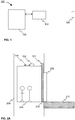
- Figure 1 illustrates one simplified example of the arrangement 100 for detecting at least one operational parameter of an automatic door according to the invention.
- the at least one operational parameter of the automatic door may be at least one of the following: state information, position information.
- the arrangement 100 comprises a magnetometer 102, at least one permanent magnet 104, and a control unit 106.
- the strength, i.e. the pull strength of the at least one magnet 104 may be for example between 1 to 5 kg. This, however, is a non-limiting example and even weaker or stronger magnets may also be used. The stronger the magnet is the better signal to noise ratio the magnet provides.
- the door environment comprises metal structures or objects, such as electric cabling, it is preferable to use relatively strong magnet.
- the pull strength may be defined as a force required for prizing a magnet away from a flat surface when the magnet and metal have full and direct surface-to-surface contact.
- the magnetometer 102 may be any sensor capable for detecting magnetic field.
- the magnetometer 102 may be at least one of the following: a vector magnetometer, 3D magnetometer.
- the magnetometer 102 is preferably configured to detect the magnetic field in vector format, i.e. the strength, i.e. magnitude, and the direction of the magnetic field.
- the magnetometer 102 may be arranged to at least one of the following: moving part of the door 202, 302, structure that is separate from the moving part of the door 202, 302.
- the at least one permanent magnet 104 may be arranged to the other one of the following: moving part of the door 202, 302, structure that is separate from the moving part of the door 202, 302, so that the at least one permanent magnet 104 is in an operational vicinity of the magnetometer 102 at least at one point of a motion path of the door 202, 302.
- the motion path of the door 202, 302 is the trajectory along which the door 202, 302 is configured to travel.
- the moving part of the door 202, 302 may be for example at least one of the following: hanger plate, panel. Alternatively or in addition, the moving part of the door may be any part of the door that is configured to move together with the door.
- the structure that is separate from the moving part of the door 202, 302 may be any structure arranged to the environment of the door 202, 302, for example door frame, wall, ceiling, rail along which the door is configured to move, or any fixed structure that may be arranged around the door 202, 302.
- the at least one permanent magnet 104 may be arranged to the moving part of the door 202, 302 or to the structure that is separate from the moving part of the door 202, 302 by means of the magnetic attraction of the at least one permanent magnet 104.
- the installation of the at least one permanent magnet 104 is quick and easy.
- the installation location of the at least one permanent magnet 104 does not need to be exact, which also enables quick and easy installation.
- the arrangement 100 according to the invention may be implemented at least in the following environments: an elevator environment, building environment.
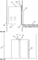
- Figures 2A and 2B illustrate some examples of the arrangement 100 according to the invention implemented in the elevator environment, wherein the arrangement 100 is configured to detect at least one operational parameter of an elevator door 202.
- the elevator comprises an elevator car 204 and a hoisting machine configured to drive the elevator car 204 in an elevator shaft 208 between the floors 210.
- An elevator control system may be configured to control the operation of the elevator.
- the elevator at a location of one floor is illustrated in Figures 2A and 2B .
- the hoisting machine and the elevator control system are not shown in Figures 2A and 2B .
- Figure 2A is illustrated an example of the invention implemented in the elevator environment, wherein the magnetometer 102 and the control unit 106 communicatively coupled to the magnetometer 102 are arranged to the roof of the elevator car 204 and the at least one permanent magnet 104 is arranged to a moving part of the elevator door 202, wherein the moving part may be a hanger plate of the door 202, for example.
- Figure 2B is illustrated another example of the invention implemented in the elevator environment, wherein the magnetometer 102 and the control unit 106 communicatively coupled to the magnetometer 102 are arranged to a moving part of the elevator door 202, such as to a hanger plate of the door 202, and the at least one permanent magnet 104 is arranged to the roof of the elevator car 204.
- the moving part of the door 202 may be also a landing door 206 in addition to the above discussed examples of the moving part of the door.
- the structure that is separate from the moving part of the door 202, 302 may be also at least one of the following: elevator car 204, elevator car frame, or any other part moving along the elevator car 204 in addition to the above discussed structures that are separate from the moving part of the door.
- Figures 3A and 3B illustrate some examples of the arrangement 100 according to the invention implemented in the building environment, wherein the arrangement 100 is configured to detect at least one operational parameter of an automatic door 302 of a building.
- Figure 3A is illustrated an example of the invention implemented in the building environment, wherein the magnetometer 102 and the control unit 106 communicatively coupled to the magnetometer 102 are arranged on a wall 304 of the building and the at least one permanent magnet is arranged to a moving part of the automatic door 302, wherein the moving part may be a hanger plate of the door 302, for example.
- the structure that is separate from the moving part of the door to which the magnetometer 102 is arranged may be other than the wall as described above.
- Figure 3B illustrated another embodiment of the invention implemented in the building environment, wherein the magnetometer 102 and the control unit 106 communicatively coupled to the magnetometer 102 are arranged to a moving part of the automatic door 302, such as to a hanger plate of the door 302, and the at least one permanent magnet 104 is arranged on the wall 304 of the building.
- the structure that is separate from the moving part of the door to which the at least one permanent magnet 104 is arranged may be other than the wall 304 as described above.
- the magnetic field generated by the at least one permanent magnet 104 changes the magnetic field at the site of the magnetometer 102 depending on the position of the door 202, 302.
- the magnetometer 102 is configured to detect data representing the magnetic field generated by the at least one permanent magnet 104 during a predefined time.
- the data representing the magnetic field may be for example magnetic flux density, wherein the magnetic flux density is a vector quantity having strength, i.e. magnitude, and direction.
- the predefined time may be a short time, such as 100 - 750 milliseconds, so that the at least one operational parameter of the door 202, 302 is not changed during the detection.
- the predefined time may be preferably 500 milliseconds, for example.
- the magnetometer 102 is configured to transmit the detected data to the control unit 106.
- the control unit 106 is configured to receive and store the detected data from the magnetometer 102.
- the data received by the control unit 106 from the magnetometer 102 may be the raw data detected by the magnetometer 102 or it may be data processed by the magnetometer 102 before transmitting the data to the control unit 106.
- the control unit 106 is further configured to define the at least one operational parameter of the automatic door 202, 302 from the received data.
- the control unit 106 may define the state information of the door 202, 302 by comparing the detected data to an idle noise of the magnetometer 102.
- the idle noise of the magnetometer 102 may be a predefined magnetometer specific value representing the noise that is present when no signal is applied to the magnetometer 102.
- the state information of the door 202, 302 may be at least one of the following: moving, open, closed.
- the control unit 106 may define the state information to be moving, if the variance of the detected data is defined to be higher than the idle noise of the magnetometer 102. Alternatively, if the variance of the detected data is defined to correspond to the idle noise of the magnetometer 102, the state information may be defined to be open or closed.
- the control unit 106 is further configured to compare the detected data to a door environment specific reference value. If the average of the detected data is defined to differ from the door environment specific reference value more than a predefined limit, the state information of the door 202, 302 may be defined to be open. Alternatively, if the average of the detected data is defined to differ from the door environment specific reference value less than the predefined limit, the state information of the door 202, 302 may be defined to be closed.
- the door environment specific reference value is an average value of previously detected and stored data representing the magnetic field created by the at least one permanent magnet at said door environment, when the door 202, 302 is defined to be in the closed state.
- one or more test runs are carried out in the operation environment of the arrangement in order to generate initial value for each door environment specific reference values.
- the one or more test runs may be carried out at each floor in order to generate initial values for the door environment specific reference values at each floor.
- Each door 202, 302 has its own door environment that has an influence on the magnetic field around the door 202, 302.
- Each metal structures or objects around the door 202, 302 change the magnetic field around the door 202, 302.
- each door may be recognized by means of the characteristic magnetic field of the door environment of said door, if the characteristic magnetic field of each door environment is known.
- the characteristic magnetic field of each door environment For example in the elevator environment there are several structures or objects that have an influence on the magnetic field of each door environment. For example elevator shaft 208, counterweight, hoisting ropes, and floor levels 210 cause different magnetic field for each door environment at different floors.
- the predefined limit of the door environment specific reference value may depend on the number of permanent magnets 104, distance between the magnetometer 102 and the at least one magnet 104, and the level of the idle noise of the magnetometer 102, for example.
- the predefined limit may be for example between 2.5 - 10 ⁇ T.
- the predefined limit may be 5 ⁇ T in order to reliably define the difference between open and closed states. This, however, is a non-limiting example.
- the state information of the automatic door may be defined from the detected data.
- the position information of the door at the time of the detection may be defined from the detected data.
- the magnetometer is configured to detect the magnetic field as a vector format
- the arrangement described above may also be implemented to define position information of the automatic door at the motion path of the door from the detected magnetic field.
- the control unit 106 may be configured to define the position information of the automatic door 202, 302 by comparing the detected data to a previously generated and stored magnetic map of the motion path of the door 202, 302.
- the magnetic map of the motion path of the door 202, 302 represents the magnetic field at each point of the motion path of the door 202, 302.
- the arrangement 100 may be taken into actual operation one or more test runs are carried out in the operation environment of the arrangement 100 in order to generate initial value for each door environment specific reference values.
- the magnetic map of the motion path of the door may be detected and stored during the one or more test runs.
- each door 202, 302 has its own door environment that has an influence on the magnetic field around the door 202, 302. Furthermore, also each point of the motion path of each door has its own characteristic magnetic field, which may be considered to be substantially static in relation to time. Thus, if the magnetic field at each point of the motion path of the door is known, i.e. previously defined, the position information of the door may be defined by comparing the detected data to the magnetic map of the motion path of the door. The position of the door at the time of detection may be defined to be the point of the motion path of the door having magnetic field data corresponding to the detected data representing the magnetic field.
- the above described detection may be started when the elevator car 204 is defined to arrive to at least one door zone of the elevator shaft 208.
- the door zone may be defined as a zone extending from a lower limit below floor level to an upper limit above the floor level in which the landing door 206 and the elevator car door 202 are in mesh and operable.
- the door zone may be determined to be from -400mm to +400mm for example.
- the door zone may be from -150 mm to +150mm.
- the at least one permanent magnet 104 is arranged in the operational vicinity of the magnetometer 102 at least at one point of a motion path of the door 202, 302.
- the magnetometer 102 may be arranged in such a way that the distance from the magnetometer 102 to the at least one permanent magnet 104 is at its minimum, when the door 202, 302 is in the open state.
- the magnetometer 102 may be arranged at a distance from the at least one permanent magnet 104, wherein the distance is defined to be at its minimum, when the door 202, 302 is in an open state.
- the arrangement 100 according to the invention is operable by using one permanent magnet 104.
- the magnetic field generated by the at least one permanent magnet 104 may be strengthen in comparison to using one permanent magnet 104.
- the detected data representing the magnetic field generated by the at least one permanent magnet 104 may be amplified.
- the signal to noise ratio may be increased in comparison to using one permanent magnet 104.
- the permanent magnets 104 may be arranged to the moving part of the door 202, 302 or to the structure that is separate from the moving part of the door 202, 302 in several ways. For example the multiple permanent magnets 104 may be stacked on top of each other.
- the multiple permanent magnets 104 may be arranged to the moving part of the door 202, 302 or to structure that is separate from the moving part of the door 202, 302 so that the multiple permanents magnets 104 are arranged a distance from each other in any kind of formation.
- the multiple permanent magnets 104 may be arranged to the landing door 206 in different ways at each floor in order to increase the difference between the characteristic magnetic fields of each floor. In this way the door environment reference value of each floor may be individualized even more. This enables that each floor may be recognized by means of the door environment reference value.
- the multiple magnets 104 may be arranged differently at each floor so that each floor has different amount of permanent magnets 104, the location of the multiple permanent magnets 104 is different at each floor, the orientation of the multiple permanent magnets 104 is different at each floor, and/or the strength of the multiple permanent magnets 104 is different at each floor, for example.
- FIG. 4 illustrates schematically an example of the control unit 106 according to the invention.
- the control unit 106 may comprise at least one processor 402, at least one memory 404, and a communication interface 406.
- the control unit 106 may further comprise at least one user interface 408.
- the at least one memory 404 may be volatile or non-volatile.
- the at least one memory 404 is configured to store portions of computer program code 405a-405n and any data values or parameters.
- the at least one memory 404 is not limited to a certain type of memory only, but any memory type suitable for storing the described pieces of information may be applied in the context of the invention.
- the at least one processor 402 herein refers to any unit suitable for processing information and control the operation of the control unit 106, among other tasks.
- the operations may also be implemented with a microcontroller solution with embedded software.
- the above mentioned elements may be communicatively coupled to each other with e.g. an internal bus.
- the communication interface 406 provides an interface for communication with any external unit, such as magnetometer 102, database and/or external systems.
- the communication interface 406 may be based on one or more known wired or wireless communication technologies, in order to exchange pieces of information as described earlier.
- the at least one processor 402 of the control unit 106 is at least configured to implement at least some of the above described operations of the control unit 106 and the method step described later for detecting at least one operational parameter of an automatic door 202, 302.
- the implementation of the operations and/method steps may be achieved by arranging the at least one processor 402 to execute at least some portion of computer program code 405a-405n stored in the at least one memory 404 causing the at least one processor 402, and thus the control unit 106, to implement one or more operations as described above.
- the at least one processor 106 is thus arranged to access the at least one memory 404 and retrieve and store any information therefrom and thereto.
- the communication interface 406 of the control unit 106 may be also used for providing power to the control unit 106.
- the control unit 106 may be powered via the communication interface 406 by mains or any external device, for example.
- the control unit 106 may comprise a battery in order to provide power to the control unit 106.
- FIG. 5 illustrates a schematic example of a magnetometer according to the invention.
- the magnetometer 102 may comprise one or more processors 502, one or more memories 504 being volatile or non-volatile for storing portions of computer program code 505a-505n and any data values or parameters, a communication interface 506, and detecting related devices 508 for detecting the magnetic field.
- the mentioned elements may be communicatively coupled to each other with e.g. an internal bus.
- the communication interface 506 provides interface for communication with any external unit, such as with control unit 106.
- the communication interface may be based on one or more known communication technologies, either wired or wireless, in order to exchange pieces of information as described earlier.
- the communication interface 506 of the magnetometer 102 may also be used for providing power to the magnetometer 102 from mains of any external unit, such as the control unit 106.
- the magnetometer 102 may comprise a battery in order to provide power to the magnetometer 102.
- arrangement 100 by the magnetometer 102 and the control unit 106 are implemented as separate units that are communicatively coupled to each other.
- the magnetometer 102 and the control unit 106 may be implemented as one combined unit comprising the magnetometer 102 and the control unit 106.
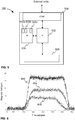
- Figure 6 illustrates some example results obtained with an example arrangement according to the invention for detecting at least one operational parameter of an automatic door.
- the arrangement is implemented in elevator environment and the operational parameter is the state information.
- One permanent magnet having pull strength of 2.4 kg is attached to a hanger plate of the automatic door and the magnetometer is arranged on the roof of the elevator car close to the center line of the door opening.
- the example results are achieved by arranging the magnetometer at three different distances from the door. The three distances used in the example are 0, 30, and 60 centimeters.
- the control unit is communicatively coupled to the magnetometer and arranged also on the roof of the elevator car.
- the detected magnetic field is presented as a function of time, i.e. on the x-axis is presented time samples and on the y-axis is presented the detected magnetic field density.
- the line 602 represents the detected magnetic field, when the distance between the magnetometer and the door is 0 centimeters.
- the line 604 represents the detected magnetic field, when the distance between the magnetometer and the door is 30 centimeters.
- the line 606 represents the detected magnetic field, when the distance between the magnetometer and the door is 60 centimeters.
- the example results illustrated in Figure 6 clearly presents that the detected magnetic field is higher when the magnetometer is closer to the door and thus also closer to the magnet.
- the automatic door starts to open around time sample 200 (depending on the distance between the magnetometer and the door), wherein the detected magnetic field is more than the predefined limit, which is in this example 5 ⁇ T.
- the door Before that the door may be defined to be closed, because the detected magnetic field is less than the predefined limit, i.e. 5 ⁇ T.
- the door may be defined to be fully open around time sample 300, where the detected magnetic field settles to a steady level.
- time samples 500-600 dependinging again on the distance between the magnetometer and the door
- the door starts to close and is detected to be fully closed around the samples 650 (depending again on the distance between the magnetometer and the door).
- the above example shows that the state of the automatic door may be defined with the arrangement according to the invention.
- FIG. 7 illustrates another example results with the same example arrangement as described above, wherein the detection of automatic door reopenings is illustrated.
- the line 702 represents the detected magnetic field, when the distance between the magnetometer and the door is 30 centimeters.
- the line 704 represents the detected magnetic field, when the distance between the magnetometer and the door is 60 centimeters.
- the automatic door is arranged to open and close six times so that the door is not fully closed every time, but in some cases the door is arranged to close only a little and to reopen before the door is fully closed. From the lines 702 and 704 illustrating the detected magnetic field from distances of 30 and 60 centimeters, respectively, can be easily deduced all the openings and closings of the automatic door.
- the door is not fully closed at least around time samples 200, 300, and 350.
- the above example shows that the number of reopenings of the automatic door may be deducted with the arrangement according to the invention. Furthermore, from the detected magnetic field data the time spent in the opening state may be deducted.
- the invention relates to a method for detecting at least one operational parameter of an automatic door by using the above presented arrangement 100.
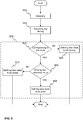
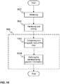
- Figure 8 schematically illustrates the method according to the invention as a flow chart.
- the magnetometer detects 802 data representing the magnetic field generated by at least one permanent magnet during a predefined time.
- the control unit receives and stores 804 the detected data from the magnetometer.
- the control unit defines 806 the at least one operational parameter of the door from the received data.
- Figure 9 schematically illustrates the flow chart of Figure 8 in more detailed manner, wherein the at least one operational parameter is the state information of the automatic door 202, 302.
- the state information of the door may be defined by comparing the detected data to the idle noise of the magnetometer as described.
- the idle noise of the magnetometer may be a predefined magnetometer specific value representing the noise that is present when no signal is applied to the magnetometer.
- the control unit defines 806 the state information of the door by comparing 902 the detected data to the idle noise of the magnetometer.
- the control unit may define the state information of the door to be moving 904 if the variance of the detected data is defined to be higher than the idle noise of the magnetometer.
- the control unit compares 906 the detected data to a door environment specific reference value as described in order to define whether the state information of the door is open or closed. If the average of the detected data is defined to differ from the door environment specific reference value more than a predefined limit, the control unit defines 908 that the state information of the door may be open. Alternatively, if the average of the detected data is defined to differ from the door environment specific reference value less than the predefined limit, the control unit defines 910 that the state information of the door may be closed.
- the door environment specific reference value may be an average value of previously detected and stored data representing the magnetic field created by the at least one permanent magnet at said door environment, when the door 202, 302 is defined to be in the closed state as described earlier.
- Figure 10 schematically illustrates the flow chart of Figure 8 in more detailed manner, wherein the at least one operational parameter of the automatic door is position information of the automatic door 202, 302. Especially the step 806 becomes clear from Figure 10 .
- the control unit defines 806 the position information of the door by comparing 1002 the detected data to a previously generated and stored magnetic map of the motion path of the door wherein the magnetic map of the motion path of the door represents the magnetic field at each point of the motion path of the door as described above.
- the magnetic map of the motion path of the door may be detected and stored during the one or more test runs as also described earlier.
- the control unit defines 1004 the position of the door at the time of detection to be the point of the motion path of the door having magnetic field data corresponding to the detected data representing the magnetic field.
- the moving parts of the door 202, 302 or the structure that is separate from the moving part of the door 202, 302 are typically made of metal, which naturally generates also at least a small magnetic field, which the at least one permanent magnet 104 is configured to amplify when attached to it.
- the magnetometer 102 is configured to detect the magnetic field generated by the at least one permanent magnet 104 together with the magnetic field generated by the moving parts of the door 202, 302 or the structure that is separate from the moving part of the door 202, 302.
- the arrangement 100 and the method described above may be used to accurately provide the at least one operational parameter of the automatic door.
- the at least one permanent magnet is required to generate a magnetic field having a magnitude that may be distinguished from the magnetic noise around the door environment, i.e. the at least one magnet is required to be relatively strong, for example even more than 5 kg.
- the magnetic noise around the door environment may be caused for example by cablings, motor or other structures or objects comprising metal.
- the state information of the automatic door in turn, may be defined accurately even with at least one permanent magnet generating only a weak magnetic field, for example with a permanent magnet having strength even less than 1 kg.
- the time spent in the open state and the number of reopenings which are two most important characteristics of door operation, may be deduced. More over the arrangement described above enables an arrangement for detecting the at least one operational parameter of an automatic door, wherein the arrangement does not require anything to be connected with a wire to the moving parts of the automatic door, because no wires are needed between the magnetometer and the at least one permanent magnet. Furthermore, the arrangement presented above does not require a battery powered devices to be installed to the door panel because of using permanent magnets.
- the above described arrangement 100 and method according to the invention may be used especially, when the access to a door control system is not available, for example due to unknown interface or protocol in order to obtain accurately the state information of an automatic door.
- the above described arrangement 100 may be implemented as a retrofitted arrangement in an already existing automatic door system regardless of the producer of the automatic door system, wherein the automatic door system may comprise at least the automatic door and the door control system.
- the arrangement according to invention may be arranged to any automatic door.
- the arrangement according to the invention may be used to obtain additional state information of an automatic door in addition to the information obtained by means of the door control system.
Landscapes
- Physics & Mathematics (AREA)
- Condensed Matter Physics & Semiconductors (AREA)
- General Physics & Mathematics (AREA)
- Engineering & Computer Science (AREA)
- Automation & Control Theory (AREA)
- Elevator Door Apparatuses (AREA)
- Power-Operated Mechanisms For Wings (AREA)
Abstract
Description
- The invention concerns in general the technical field of an automatic door technology. Especially the invention concerns observation of an operation of the automatic door.
- Automatic doors are used in a variety of environments, such as in elevators and in buildings. The automatic doors refer to door solutions in which the door is configured to be operated without specific action by a user of a door. Information about the at least one operational parameter of an automatic door is important for many reasons, for example for safety reasons. The at least one operational parameter of the automatic door may be at least state information or position information. For example the state information of the door gives advantageous information about the operation of the door. Different door states may be open, closed, or moving. For example, if the door is detected to perform multiple subsequent closing-opening cycles, it may indicate some failure in the operation of the door. Thus, it may be useful to observe the at least one operational information of the door.
- According to one known solution the at least one operational parameter of the door may be obtained substantially accurately from the control system of the door. For example in elevator environment, at least one operational parameter of the door may be obtained from the elevator control system. However, if the access to the control system of the door is blocked or some other way unreachable for example due to unknown interface or protocol, the at least one operational parameter of the door cannot be obtained from the control system of the door. In that case other solutions for obtaining the at least one operational parameter of the door need to be found.
- According to one prior art solution the operational parameter of the door, such as state or position, in the elevator environment may be obtained by means of a camera, such as a still camera or a video camera. Furthermore, the operational parameter of the door may be ascertained by means of a magnetometer attached to the elevator car. The magnetometer configured to measure the magnetic field around the measuring location is primarily intended to be used for determining the location and/or the speed of the elevator car travelling in an elevator shaft, but it may also be used to ascertain the state or position of the door of the elevator car, for example whether the elevator door is open or closed.
- Hence, there is need to develop further solutions to detect at least one operational parameter of the door, when the access to the door control unit is unavailable.
- An objective of the invention is to present an arrangement and a method for detecting at least one operational parameter of the door of an automatic door. Another objective of the invention is that the arrangement and method for detecting at least one operational parameter of the door of the automatic door enable obtaining the at least one operational parameter of the door, when the access to a door control unit is not available.
- The objectives of the invention are reached by an arrangement and a method as defined by the respective independent claims.
- According to a first aspect, an arrangement for detecting at least one operational parameter of the door of an automatic door is provided, the arrangement comprising: a magnetometer arranged to at least one of the following: moving part of the door, structure that is separate from the moving part of the door, and at least one permanent magnet arranged to the other one of the following: moving part of the door, structure that is separate from the moving part of the door, so that the at least one permanent magnet is in an operational vicinity of the magnetometer at least at one point of a motion path of the door, wherein the magnetometer is configured to detect data representing the magnetic field generated by the at least one permanent magnet during a predefined time, and wherein the arrangement further comprising a control unit configured to receive and store the detected data from the magnetometer, and in response to receiving the detected data the control unit is configured to define the at least one operational parameter of the door of the door from the received data.
- Moreover, the at least one operational parameter of the automatic door may be at least one of the following: state information, position information.
- Furthermore, the state information of the door may be defined by comparing the detected data to an idle noise of the magnetometer.
- Moreover, state information of the door may be defined to be: moving, if the variance of the detected data is defined to be higher than the idle noise of the magnetometer, open, if the variance of the detected data is defined to correspond to the idle noise of the magnetometer and if the average of the detected data is defined to differ from a door environment specific reference value more than a predefined limit, or closed, if the variance of the detected data is defined to correspond to the idle noise of the magnetometer and if the average of the detected data is defined to differ from the door environment specific reference value less than the predefined limit.
- The door environment specific reference value may be an average value of previously detected and stored data representing the magnetic field created by the permanent magnet at the said door environment, when the door is defined to be in closed state.
- Alternatively or in addition, the position information of the automatic door may be defined by comparing the detected data to a previously generated and stored magnetic map of the motion path of the door, wherein the magnetic map of the motion path of the door represents the magnetic field at each point of the motion path of the door.
- Furthermore, the position of the door at the time of detection may be defined to be the point of the motion path of the door having magnetic field data corresponding to the detected data.
- Furthermore, the data representing the magnetic field may be magnetic flux density, wherein the magnetic flux density is a vector quantity having strength, i.e. magnitude, and direction.
- Alternatively or in addition, the magnetometer and the control unit may be implemented as one combined unit.
- Furthermore, the moving part of the door may be one of the following: hanger plate, panel.
- The arrangement may be implemented in an elevator environment in order to detect state information of a door of an elevator car. Alternatively or in addition, the arrangement may be implemented in a building environment in order to detect state information of a door of a building.
- According to a second aspect, a method for detecting at least one operational parameter of an automatic door is provided, the method comprising: obtaining from a magnetometer data representing the magnetic field generated by at least one permanent magnet during a predefined time, wherein the magnetometer is arranged to at least one of the following: moving part of the door, structure that is separate from the moving part of the door, and the at least one permanent magnet is arranged to the other one of the following: moving part of the door, structure that is separate from the moving part of the door, so that the at least one permanent magnet is in an operational vicinity of the magnetometer at least at one point of a motion path of the door, storing the detected data from the magnetometer, and defining in response to receiving the detected data the at least one operational parameter of the door from the received data.
- Moreover, the at least one operational parameter of the automatic door may be at least one of the following: state information, position information.
- Furthermore, the state information of the door may be defined by comparing the detected data to an idle noise of the magnetometer.
- Moreover, the state information of the door may be defined to be: moving, if the variance of the detected data is defined to be higher than the idle noise of the magnetometer, open, if the variance of the detected data is defined to correspond to the idle noise of the magnetometer and if the average of the detected data is defined to differ from a door environment specific reference value more than a predefined limit, or closed, if the variance of the detected data is defined to correspond to the idle noise of the magnetometer and if the average of the detected data is defined to differ from the door environment specific reference value less than the predefined limit.
- Alternatively or in addition, the position information of the automatic door may be defined by comparing the detected data to a previously generated and stored magnetic map of the motion path of the door, wherein the magnetic map of the motion path of the door represents the magnetic field at each point of the motion path of the door.
- Furthermore, the position of the door at the time of detection may be defined to be the point of the motion path of the door having magnetic field data corresponding to the detected data.
- The exemplary embodiments of the invention presented in this patent application are not to be interpreted to pose limitations to the applicability of the appended claims. The verb "to comprise" is used in this patent application as an open limitation that does not exclude the existence of also un-recited features. The features recited in depending claims are mutually freely combinable unless otherwise explicitly stated.
- The novel features which are considered as characteristic of the invention are set forth in particular in the appended claims. The invention itself, however, both as to its construction and its method of operation, together with additional objectives and advantages thereof, will be best understood from the following description of specific embodiments when read in connection with the accompanying drawings.
- The embodiments of the invention are illustrated by way of example, and not by way of limitation, in the figures of the accompanying drawings.
-
Figure 1 illustrates schematically one example of the arrangement according to the invention. -
Figure 2A illustrates schematically one example of the arrangement according to the invention implemented in an elevator environment. -
Figure 2B illustrates schematically another example of the arrangement according to the invention implemented in an elevator environment. -
Figure 3A illustrates schematically one example of the arrangement according to the invention implemented in a building environment. -
Figure 3B illustrates schematically another example of the arrangement according to the invention implemented in a building environment. -
Figure 4 illustrates schematically one example of a control unit according the invention. -
Figure 5 illustrates schematically an example of a magnetometer according the invention. -
Figure 6 illustrates schematically one example of results obtained with the arrangement according to the invention. -
Figure 7 illustrates schematically another example of results obtained with the arrangement according to the invention. -
Figure 8 illustrates schematically an example of the method according to the invention. -
Figure 9 illustrates schematically a more detailed example of the method according to the invention. -
Figure 10 illustrates schematically another more detailed example of the method according to the invention. -
Figure 1 illustrates one simplified example of thearrangement 100 for detecting at least one operational parameter of an automatic door according to the invention. The at least one operational parameter of the automatic door may be at least one of the following: state information, position information. Thearrangement 100 comprises amagnetometer 102, at least onepermanent magnet 104, and acontrol unit 106. The strength, i.e. the pull strength of the at least onemagnet 104 may be for example between 1 to 5 kg. This, however, is a non-limiting example and even weaker or stronger magnets may also be used. The stronger the magnet is the better signal to noise ratio the magnet provides. Especially, when the door environment comprises metal structures or objects, such as electric cabling, it is preferable to use relatively strong magnet. The pull strength may be defined as a force required for prizing a magnet away from a flat surface when the magnet and metal have full and direct surface-to-surface contact. Themagnetometer 102 may be any sensor capable for detecting magnetic field. Themagnetometer 102 may be at least one of the following: a vector magnetometer, 3D magnetometer. Themagnetometer 102 is preferably configured to detect the magnetic field in vector format, i.e. the strength, i.e. magnitude, and the direction of the magnetic field. - The
magnetometer 102 may be arranged to at least one of the following: moving part of thedoor door permanent magnet 104 may be arranged to the other one of the following: moving part of thedoor door permanent magnet 104 is in an operational vicinity of themagnetometer 102 at least at one point of a motion path of thedoor door door magnetometer 102 is meant in the context of this application the distance from the magnetometer that is within the operating range of the magnetometer, i.e. the space around the magnetometer within the magnetometer may detect the magnetic field around it. The moving part of thedoor door door door permanent magnet 104 may be arranged to the moving part of thedoor door permanent magnet 104. Thus, the installation of the at least onepermanent magnet 104 is quick and easy. Furthermore, the installation location of the at least onepermanent magnet 104 does not need to be exact, which also enables quick and easy installation. - The
arrangement 100 according to the invention may be implemented at least in the following environments: an elevator environment, building environment.Figures 2A and2B illustrate some examples of thearrangement 100 according to the invention implemented in the elevator environment, wherein thearrangement 100 is configured to detect at least one operational parameter of anelevator door 202. The elevator comprises anelevator car 204 and a hoisting machine configured to drive theelevator car 204 in anelevator shaft 208 between thefloors 210. An elevator control system may be configured to control the operation of the elevator. For sake of clarity the elevator at a location of one floor is illustrated inFigures 2A and2B . Furthermore, for sake of clarity the hoisting machine and the elevator control system are not shown inFigures 2A and2B . - In
Figure 2A is illustrated an example of the invention implemented in the elevator environment, wherein themagnetometer 102 and thecontrol unit 106 communicatively coupled to themagnetometer 102 are arranged to the roof of theelevator car 204 and the at least onepermanent magnet 104 is arranged to a moving part of theelevator door 202, wherein the moving part may be a hanger plate of thedoor 202, for example. InFigure 2B is illustrated another example of the invention implemented in the elevator environment, wherein themagnetometer 102 and thecontrol unit 106 communicatively coupled to themagnetometer 102 are arranged to a moving part of theelevator door 202, such as to a hanger plate of thedoor 202, and the at least onepermanent magnet 104 is arranged to the roof of theelevator car 204. For sake of clarity inFigure 2B only one unit arranged to the moving part of thedoor 202 is shown, however the unit comprises both themagnetometer 102 and thecontrol unit 106 as the reference numbers inFigure 2B indicate. In the elevator environment the moving part of thedoor 202 may be also alanding door 206 in addition to the above discussed examples of the moving part of the door. Alternatively or in addition, in the elevator environment the structure that is separate from the moving part of thedoor elevator car 204, elevator car frame, or any other part moving along theelevator car 204 in addition to the above discussed structures that are separate from the moving part of the door. -
Figures 3A and3B illustrate some examples of thearrangement 100 according to the invention implemented in the building environment, wherein thearrangement 100 is configured to detect at least one operational parameter of anautomatic door 302 of a building. InFigure 3A is illustrated an example of the invention implemented in the building environment, wherein themagnetometer 102 and thecontrol unit 106 communicatively coupled to themagnetometer 102 are arranged on awall 304 of the building and the at least one permanent magnet is arranged to a moving part of theautomatic door 302, wherein the moving part may be a hanger plate of thedoor 302, for example. Alternatively or in addition, the structure that is separate from the moving part of the door to which themagnetometer 102 is arranged may be other than the wall as described above. InFigure 3B illustrated another embodiment of the invention implemented in the building environment, wherein themagnetometer 102 and thecontrol unit 106 communicatively coupled to themagnetometer 102 are arranged to a moving part of theautomatic door 302, such as to a hanger plate of thedoor 302, and the at least onepermanent magnet 104 is arranged on thewall 304 of the building. Alternatively or in addition, the structure that is separate from the moving part of the door to which the at least onepermanent magnet 104 is arranged may be other than thewall 304 as described above. - When the
door door permanent magnet 104 changes the magnetic field at the site of themagnetometer 102 depending on the position of thedoor magnetometer 102 is configured to detect data representing the magnetic field generated by the at least onepermanent magnet 104 during a predefined time. The data representing the magnetic field may be for example magnetic flux density, wherein the magnetic flux density is a vector quantity having strength, i.e. magnitude, and direction. The predefined time may be a short time, such as 100 - 750 milliseconds, so that the at least one operational parameter of thedoor magnetometer 102 is configured to transmit the detected data to thecontrol unit 106. Thecontrol unit 106 is configured to receive and store the detected data from themagnetometer 102. The data received by thecontrol unit 106 from themagnetometer 102 may be the raw data detected by themagnetometer 102 or it may be data processed by themagnetometer 102 before transmitting the data to thecontrol unit 106. In response to receiving the detected data thecontrol unit 106 is further configured to define the at least one operational parameter of theautomatic door - Next it is described how the state information of the
automatic door 202, 303 is defined from the received data. Alternatively or in addition, the position information of theautomatic door 202, 203 may be defined from the received data as will be described later in this application. Thecontrol unit 106 may define the state information of thedoor magnetometer 102. The idle noise of themagnetometer 102 may be a predefined magnetometer specific value representing the noise that is present when no signal is applied to themagnetometer 102. - The state information of the
door control unit 106 may define the state information to be moving, if the variance of the detected data is defined to be higher than the idle noise of themagnetometer 102. Alternatively, if the variance of the detected data is defined to correspond to the idle noise of themagnetometer 102, the state information may be defined to be open or closed. In order to define whether the state information of thedoor control unit 106 is further configured to compare the detected data to a door environment specific reference value. If the average of the detected data is defined to differ from the door environment specific reference value more than a predefined limit, the state information of thedoor door - The door environment specific reference value is an average value of previously detected and stored data representing the magnetic field created by the at least one permanent magnet at said door environment, when the
door door door door door example elevator shaft 208, counterweight, hoisting ropes, andfloor levels 210 cause different magnetic field for each door environment at different floors. - The predefined limit of the door environment specific reference value may depend on the number of
permanent magnets 104, distance between themagnetometer 102 and the at least onemagnet 104, and the level of the idle noise of themagnetometer 102, for example. The predefined limit may be for example between 2.5 - 10 µT. Preferably, the predefined limit may be 5 µT in order to reliably define the difference between open and closed states. This, however, is a non-limiting example. - Above it is described how the state information of the automatic door may be defined from the detected data. Next it is described how the position information of the door at the time of the detection may be defined from the detected data. Because the magnetometer is configured to detect the magnetic field as a vector format, the arrangement described above may also be implemented to define position information of the automatic door at the motion path of the door from the detected magnetic field.
- The
control unit 106 may be configured to define the position information of theautomatic door door door door arrangement 100 may be taken into actual operation one or more test runs are carried out in the operation environment of thearrangement 100 in order to generate initial value for each door environment specific reference values. Alternatively or in addition, the magnetic map of the motion path of the door may be detected and stored during the one or more test runs. - As also described above each
door door - In the elevator environment the above described detection may be started when the
elevator car 204 is defined to arrive to at least one door zone of theelevator shaft 208. The door zone may be defined as a zone extending from a lower limit below floor level to an upper limit above the floor level in which thelanding door 206 and theelevator car door 202 are in mesh and operable. The door zone may be determined to be from -400mm to +400mm for example. Preferably, the door zone may be from -150 mm to +150mm. When arriving to the door zone theelevator car 204 is allowed to begin to open the doors even before theelevator car 204 is stopped. - Above it is defined that the at least one
permanent magnet 104 is arranged in the operational vicinity of themagnetometer 102 at least at one point of a motion path of thedoor door magnetometer 102 may be arranged in such a way that the distance from themagnetometer 102 to the at least onepermanent magnet 104 is at its minimum, when thedoor magnetometer 102 may be arranged at a distance from the at least onepermanent magnet 104, wherein the distance is defined to be at its minimum, when thedoor - As described above the
arrangement 100 according to the invention is operable by using onepermanent magnet 104. However, by using multiplepermanent magnets 104 the magnetic field generated by the at least onepermanent magnet 104 may be strengthen in comparison to using onepermanent magnet 104. Thus, also the detected data representing the magnetic field generated by the at least onepermanent magnet 104 may be amplified. Furthermore, by using multiplepermanent magnets 104 the signal to noise ratio may be increased in comparison to using onepermanent magnet 104. When multiplepermanent magnets 104 are used thepermanent magnets 104 may be arranged to the moving part of thedoor door permanent magnets 104 may be stacked on top of each other. Alternatively or in addition, the multiplepermanent magnets 104 may be arranged to the moving part of thedoor door multiple permanents magnets 104 are arranged a distance from each other in any kind of formation. - According to one embodiment of the invention implemented in the elevator environment the multiple
permanent magnets 104 may be arranged to thelanding door 206 in different ways at each floor in order to increase the difference between the characteristic magnetic fields of each floor. In this way the door environment reference value of each floor may be individualized even more. This enables that each floor may be recognized by means of the door environment reference value. Themultiple magnets 104 may be arranged differently at each floor so that each floor has different amount ofpermanent magnets 104, the location of the multiplepermanent magnets 104 is different at each floor, the orientation of the multiplepermanent magnets 104 is different at each floor, and/or the strength of the multiplepermanent magnets 104 is different at each floor, for example. -
Figure 4 illustrates schematically an example of thecontrol unit 106 according to the invention. Thecontrol unit 106 may comprise at least oneprocessor 402, at least onememory 404, and acommunication interface 406. Thecontrol unit 106 may further comprise at least oneuser interface 408. The at least onememory 404 may be volatile or non-volatile. Furthermore, the at least onememory 404 is configured to store portions ofcomputer program code 405a-405n and any data values or parameters. The at least onememory 404 is not limited to a certain type of memory only, but any memory type suitable for storing the described pieces of information may be applied in the context of the invention. Similarly, the at least oneprocessor 402 herein refers to any unit suitable for processing information and control the operation of thecontrol unit 106, among other tasks. The operations may also be implemented with a microcontroller solution with embedded software. The above mentioned elements may be communicatively coupled to each other with e.g. an internal bus. Thecommunication interface 406 provides an interface for communication with any external unit, such asmagnetometer 102, database and/or external systems. Thecommunication interface 406 may be based on one or more known wired or wireless communication technologies, in order to exchange pieces of information as described earlier. - The at least one
processor 402 of thecontrol unit 106 is at least configured to implement at least some of the above described operations of thecontrol unit 106 and the method step described later for detecting at least one operational parameter of anautomatic door processor 402 to execute at least some portion ofcomputer program code 405a-405n stored in the at least onememory 404 causing the at least oneprocessor 402, and thus thecontrol unit 106, to implement one or more operations as described above. The at least oneprocessor 106 is thus arranged to access the at least onememory 404 and retrieve and store any information therefrom and thereto. - Alternatively or in addition to the above described, the
communication interface 406 of thecontrol unit 106 may be also used for providing power to thecontrol unit 106. Moreover, thecontrol unit 106 may be powered via thecommunication interface 406 by mains or any external device, for example. Alternatively or in addition, thecontrol unit 106 may comprise a battery in order to provide power to thecontrol unit 106. -
Figure 5 illustrates a schematic example of a magnetometer according to the invention. Themagnetometer 102 may comprise one ormore processors 502, one ormore memories 504 being volatile or non-volatile for storing portions ofcomputer program code 505a-505n and any data values or parameters, acommunication interface 506, and detectingrelated devices 508 for detecting the magnetic field. The mentioned elements may be communicatively coupled to each other with e.g. an internal bus. Thecommunication interface 506 provides interface for communication with any external unit, such as withcontrol unit 106. The communication interface may be based on one or more known communication technologies, either wired or wireless, in order to exchange pieces of information as described earlier. - Alternatively or in addition to the above described, the
communication interface 506 of themagnetometer 102 may also be used for providing power to themagnetometer 102 from mains of any external unit, such as thecontrol unit 106. Alternatively or in addition, themagnetometer 102 may comprise a battery in order to provide power to themagnetometer 102. - Above it is described so that
arrangement 100 by themagnetometer 102 and thecontrol unit 106 are implemented as separate units that are communicatively coupled to each other. Alternatively, themagnetometer 102 and thecontrol unit 106 may be implemented as one combined unit comprising themagnetometer 102 and thecontrol unit 106. -
Figure 6 illustrates some example results obtained with an example arrangement according to the invention for detecting at least one operational parameter of an automatic door. In this example the arrangement is implemented in elevator environment and the operational parameter is the state information. One permanent magnet having pull strength of 2.4 kg is attached to a hanger plate of the automatic door and the magnetometer is arranged on the roof of the elevator car close to the center line of the door opening. The example results are achieved by arranging the magnetometer at three different distances from the door. The three distances used in the example are 0, 30, and 60 centimeters. The control unit is communicatively coupled to the magnetometer and arranged also on the roof of the elevator car. - In
Figure 6 the detected magnetic field is presented as a function of time, i.e. on the x-axis is presented time samples and on the y-axis is presented the detected magnetic field density. Theline 602 represents the detected magnetic field, when the distance between the magnetometer and the door is 0 centimeters. Theline 604 represents the detected magnetic field, when the distance between the magnetometer and the door is 30 centimeters. Theline 606 represents the detected magnetic field, when the distance between the magnetometer and the door is 60 centimeters. The example results illustrated inFigure 6 clearly presents that the detected magnetic field is higher when the magnetometer is closer to the door and thus also closer to the magnet. Furthermore, it can be seen fromFigure 6 that the automatic door starts to open around time sample 200 (depending on the distance between the magnetometer and the door), wherein the detected magnetic field is more than the predefined limit, which is in this example 5 µT. Before that the door may be defined to be closed, because the detected magnetic field is less than the predefined limit, i.e. 5µT. Furthermore, the door may be defined to be fully open aroundtime sample 300, where the detected magnetic field settles to a steady level. Around time samples 500-600 (depending again on the distance between the magnetometer and the door) the door starts to close and is detected to be fully closed around the samples 650 (depending again on the distance between the magnetometer and the door). The above example shows that the state of the automatic door may be defined with the arrangement according to the invention. -
Figure 7 , in turn, illustrates another example results with the same example arrangement as described above, wherein the detection of automatic door reopenings is illustrated. Theline 702 represents the detected magnetic field, when the distance between the magnetometer and the door is 30 centimeters. Theline 704 represents the detected magnetic field, when the distance between the magnetometer and the door is 60 centimeters. In this example the automatic door is arranged to open and close six times so that the door is not fully closed every time, but in some cases the door is arranged to close only a little and to reopen before the door is fully closed. From thelines time samples - The above presented examples relating to
Figures 6 and7 do not limit the invention anyhow and the inventive idea is directly applicable in any other implementation according to the invention. - In addition to the
arrangement 100 presented above the invention relates to a method for detecting at least one operational parameter of an automatic door by using the above presentedarrangement 100. Next an example of the method according to the invention is described by referring toFigure 8. Figure 8 schematically illustrates the method according to the invention as a flow chart. As already described the magnetometer detects 802 data representing the magnetic field generated by at least one permanent magnet during a predefined time. Next the control unit receives andstores 804 the detected data from the magnetometer. In response to receiving the detected data the control unit defines 806 the at least one operational parameter of the door from the received data. -
Figure 9 schematically illustrates the flow chart ofFigure 8 in more detailed manner, wherein the at least one operational parameter is the state information of theautomatic door step 806 becomes clear fromFigure 9 . The state information of the door may be defined by comparing the detected data to the idle noise of the magnetometer as described. The idle noise of the magnetometer may be a predefined magnetometer specific value representing the noise that is present when no signal is applied to the magnetometer. The control unit defines 806 the state information of the door by comparing 902 the detected data to the idle noise of the magnetometer. The control unit may define the state information of the door to be moving 904 if the variance of the detected data is defined to be higher than the idle noise of the magnetometer. Alternatively, if the variance of the detected data is defined to correspond to the idle noise of the magnetometer, the control unit compares 906 the detected data to a door environment specific reference value as described in order to define whether the state information of the door is open or closed. If the average of the detected data is defined to differ from the door environment specific reference value more than a predefined limit, the control unit defines 908 that the state information of the door may be open. Alternatively, if the average of the detected data is defined to differ from the door environment specific reference value less than the predefined limit, the control unit defines 910 that the state information of the door may be closed. The door environment specific reference value may be an average value of previously detected and stored data representing the magnetic field created by the at least one permanent magnet at said door environment, when thedoor -
Figure 10 schematically illustrates the flow chart ofFigure 8 in more detailed manner, wherein the at least one operational parameter of the automatic door is position information of theautomatic door step 806 becomes clear fromFigure 10 . The control unit defines 806 the position information of the door by comparing 1002 the detected data to a previously generated and stored magnetic map of the motion path of the door wherein the magnetic map of the motion path of the door represents the magnetic field at each point of the motion path of the door as described above. The magnetic map of the motion path of the door may be detected and stored during the one or more test runs as also described earlier. The control unit defines 1004 the position of the door at the time of detection to be the point of the motion path of the door having magnetic field data corresponding to the detected data representing the magnetic field. - It is worthwhile to mention here that also the moving parts of the
door door permanent magnet 104 is configured to amplify when attached to it. Thus, throughout this application themagnetometer 102 is configured to detect the magnetic field generated by the at least onepermanent magnet 104 together with the magnetic field generated by the moving parts of thedoor door - The
arrangement 100 and the method described above may be used to accurately provide the at least one operational parameter of the automatic door. In order to accurately define the position information of the automatic door, the at least one permanent magnet is required to generate a magnetic field having a magnitude that may be distinguished from the magnetic noise around the door environment, i.e. the at least one magnet is required to be relatively strong, for example even more than 5 kg. The magnetic noise around the door environment may be caused for example by cablings, motor or other structures or objects comprising metal. The state information of the automatic door, in turn, may be defined accurately even with at least one permanent magnet generating only a weak magnetic field, for example with a permanent magnet having strength even less than 1 kg. - Furthermore, from the detected data representing the state information of the automatic door the time spent in the open state and the number of reopenings, which are two most important characteristics of door operation, may be deduced. More over the arrangement described above enables an arrangement for detecting the at least one operational parameter of an automatic door, wherein the arrangement does not require anything to be connected with a wire to the moving parts of the automatic door, because no wires are needed between the magnetometer and the at least one permanent magnet. Furthermore, the arrangement presented above does not require a battery powered devices to be installed to the door panel because of using permanent magnets.
- The above described
arrangement 100 and method according to the invention may be used especially, when the access to a door control system is not available, for example due to unknown interface or protocol in order to obtain accurately the state information of an automatic door. Thus, the above describedarrangement 100 may be implemented as a retrofitted arrangement in an already existing automatic door system regardless of the producer of the automatic door system, wherein the automatic door system may comprise at least the automatic door and the door control system. This means that the arrangement according to invention may be arranged to any automatic door. Alternatively, the arrangement according to the invention may be used to obtain additional state information of an automatic door in addition to the information obtained by means of the door control system. - The specific examples provided in the description given above should not be construed as limiting the applicability and/or the interpretation of the appended claims. Lists and groups of examples provided in the description given above are not exhaustive unless otherwise explicitly stated.
Claims (18)
- An arrangement (100) for detecting at least one operational parameter of an automatic door (202, 302), the arrangement (100) comprising:- a magnetometer (102) arranged to at least one of the following: moving part of the door (202, 302), structure that is separate from the moving part of the door (202, 302), and- at least one permanent magnet (104) arranged to the other one of the following: moving part of the door (202, 302), structure that is separate from the moving part of the door (202, 302), so that the at least one permanent magnet (104) is in an operational vicinity of the magnetometer (102) at least at one point of a motion path of the door (202, 302),wherein the magnetometer (102) is configured to detect data representing the magnetic field generated by the at least one permanent magnet (104) during a predefined time, and
wherein the arrangement (100) further comprising:- a control unit (106) configured to receive and store the detected data from the magnetometer (102), and in response to receiving the detected data the control unit (106) is configured to define the at least one operational parameter of the door (202, 302) from the received data. - The arrangement (100) according to claim 1, wherein the at least one operational parameter of the automatic door (202, 302) is at least one of the following: state information, position information.
- The arrangement (100) according to claim 2, wherein the state information of the door (202, 302) is defined by comparing the detected data to an idle noise of the magnetometer (102).
- The arrangement (100) according to claim 3, wherein the state information of the door (202, 302) is defined to be:- moving, if the variance of the detected data is defined to be higher than the idle noise of the magnetometer,- open, if the variance of the detected data is defined to correspond to the idle noise of the magnetometer and if the average of the detected data is defined to differ from a door environment specific reference value more than a predefined limit, or- closed, if the variance of the detected data is defined to correspond to the idle noise of the magnetometer and if the average of the detected data is defined to differ from the door environment specific reference value less than the predefined limit.
- The arrangement (100) according to claim 4, wherein the door environment specific reference value is an average value of previously detected and stored data representing the magnetic field created by the permanent magnet (104) at the said door environment, when the door (202, 302) is defined to be in closed state.
- The arrangement (100) according to claim 2, wherein the position information of the automatic door (202, 302) is defined by comparing the detected data to a previously generated and stored magnetic map of the motion path of the door (202, 302), wherein the magnetic map of the motion path of the door (202, 302) represents the magnetic field at each point of the motion path of the door (202, 302).
- The arrangement (100) according to claim 6, wherein the position of the door (202, 302) at the time of detection is defined to be the point of the motion path of the door (202, 302) having magnetic field data corresponding to the detected data.
- The arrangement (100) according to any of the preceding claims, wherein the data representing the magnetic field is magnetic flux density, wherein the magnetic flux density is a vector quantity having strength and direction.
- The arrangement (100) according to any of the preceding claims, wherein the magnetometer (102) and the control unit (106) are implemented as one combined unit.
- The arrangement (100) according to any of the preceding claims, wherein the moving part of the door (202, 302) is one of the following: hanger plate, panel.
- The arrangement (100) according to any of the preceding claims, wherein the arrangement (100) is implemented in an elevator environment in order to detect at least one operational parameter of a door (202) of an elevator car (204).
- The arrangement (100) according to any of claims 1-10, wherein the arrangement (100) is implemented in a building environment in order to detect at least one operational parameter of a door (302) of a building.
- A method for detecting at least one operational parameter of an automatic door, the method comprising:- obtaining (804) from a magnetometer data representing the magnetic field generated by at least one permanent magnet during a predefined time, wherein the magnetometer is arranged to at least one of the following: moving part of the door, structure that is separate from the moving part of the door, and the at least one permanent magnet is arranged to the other one of the following: moving part of the door, structure that is separate from the moving part of the door, so that the at least one permanent magnet is in an operational vicinity of the magnetometer at least at one point of a motion path of the door,- storing (804) the detected data from the magnetometer, and- defining (806) in response to receiving the detected data the at least one operational parameter of the door from the received data.
- The method according to claim 13, wherein the at least one operational parameter of the automatic door (202, 302) is at least one of the following: state information, position information.
- The method according to claim 14, wherein the state information of the door is defined (806) by comparing (902) the detected data to an idle noise of the magnetometer.
- The method according to claim 15, wherein the state information of the door is defined to be:- moving (904), if the variance of the detected data is defined to be higher than the idle noise of the magnetometer,- open (908), if the variance of the detected data is defined to correspond to the idle noise of the magnetometer and if the average of the detected data is defined to differ from a door environment specific reference value more than a predefined limit, or- closed (910), if the variance of the detected data is defined to correspond to the idle noise of the magnetometer and if the average of the detected data is defined to differ from the door environment specific reference value less than the predefined limit.
- The method according to claim 14, wherein the position information of the automatic door is defined by comparing (1002) the detected data to a previously generated and stored magnetic map of the motion path of the door, wherein the magnetic map of the motion path of the door represents the magnetic field at each point of the motion path of the door.
- The method according to claim 17, wherein the position of the door at the time of detection is defined (1004) to be the point of the motion path of the door having magnetic field data corresponding to the detected data.
Priority Applications (4)
| Application Number | Priority Date | Filing Date | Title |
|---|---|---|---|
| ES17151782T ES2738424T3 (en) | 2017-01-17 | 2017-01-17 | Arrangement and procedure to detect at least one operating parameter of an automatic door |
| EP17151782.4A EP3348508B1 (en) | 2017-01-17 | 2017-01-17 | An arrangement and method for detecting at least one operational parameter of an automatic door |
| US15/860,929 US10899578B2 (en) | 2017-01-17 | 2018-01-03 | Arrangement and method for detecting at least one operational parameter of an automatic door |
| CN201810040547.2A CN108483199A (en) | 2017-01-17 | 2018-01-16 | Device and method at least one operating parameter for detecting automatically-controlled door |
Applications Claiming Priority (1)
| Application Number | Priority Date | Filing Date | Title |
|---|---|---|---|
| EP17151782.4A EP3348508B1 (en) | 2017-01-17 | 2017-01-17 | An arrangement and method for detecting at least one operational parameter of an automatic door |
Publications (2)
| Publication Number | Publication Date |
|---|---|
| EP3348508A1 true EP3348508A1 (en) | 2018-07-18 |
| EP3348508B1 EP3348508B1 (en) | 2019-05-15 |
Family
ID=57868044
Family Applications (1)
| Application Number | Title | Priority Date | Filing Date |
|---|---|---|---|
| EP17151782.4A Active EP3348508B1 (en) | 2017-01-17 | 2017-01-17 | An arrangement and method for detecting at least one operational parameter of an automatic door |
Country Status (4)
| Country | Link |
|---|---|
| US (1) | US10899578B2 (en) |
| EP (1) | EP3348508B1 (en) |
| CN (1) | CN108483199A (en) |
| ES (1) | ES2738424T3 (en) |
Cited By (3)
| Publication number | Priority date | Publication date | Assignee | Title |
|---|---|---|---|---|
| EP3960675A1 (en) * | 2020-08-24 | 2022-03-02 | KONE Corporation | Monitoring of a door of an elevator with a pressure sensor |
| WO2023223073A1 (en) * | 2022-05-16 | 2023-11-23 | Wittur Holding Gmbh | System and method for detecting the position of a car door of an elevator |
| EP4324780A1 (en) * | 2022-08-15 | 2024-02-21 | Otis Elevator Company | Elevator safety devices |
Families Citing this family (6)
| Publication number | Priority date | Publication date | Assignee | Title |
|---|---|---|---|---|
| ES2738424T3 (en) * | 2017-01-17 | 2020-01-22 | Kone Corp | Arrangement and procedure to detect at least one operating parameter of an automatic door |
| US11479442B2 (en) * | 2018-04-26 | 2022-10-25 | Inventio Ag | Method for monitoring characteristics of a door motion procedure of an elevator door using a smart mobile device |
| WO2020020589A1 (en) * | 2018-07-26 | 2020-01-30 | Inventio Ag | Elevator control cabinet with a voice communication apparatus and method to monitoring a cabinet door |
| CN110231796A (en) * | 2019-04-08 | 2019-09-13 | 苏州个纳科技有限公司 | A kind of vector automatic door control system |
| JP7657755B2 (en) * | 2022-03-28 | 2025-04-07 | 株式会社日立ビルシステム | Elevator door opening/closing detection system |
| CN115043291A (en) * | 2022-07-20 | 2022-09-13 | 成都鹏业软件股份有限公司 | Method and device for detecting abnormality of elevator door |
Citations (2)
| Publication number | Priority date | Publication date | Assignee | Title |
|---|---|---|---|---|
| US20130081906A1 (en) * | 2011-09-29 | 2013-04-04 | Inventio Ag | Monitoring shaft doors |
| US20160185569A1 (en) * | 2013-08-13 | 2016-06-30 | Invention Ag | Monitoring system of an elevator installation |
Family Cites Families (10)
| Publication number | Priority date | Publication date | Assignee | Title |
|---|---|---|---|---|
| US6116381A (en) * | 1999-03-23 | 2000-09-12 | Otis Elevator Company | Passive hall fixtures mounted in elevator doors |
| CN2470327Y (en) * | 2001-02-14 | 2002-01-09 | 陈金林 | Detection device for anormal opening of elevator door |
| FI117283B (en) * | 2005-02-04 | 2006-08-31 | Kone Corp | Elevator system |
| FI20116342L (en) * | 2011-12-30 | 2013-07-01 | Rdnet Oy | Method and arrangement for determining the position and/or speed of an object adapted to move and use of the arrangement |
| CN104379480B (en) * | 2012-06-27 | 2017-03-22 | 通力股份公司 | Position and load measurement systems for elevators |
| GB2526071B (en) * | 2014-05-02 | 2018-05-23 | Ensota Ltd | A method of operating an automatic door installation |
| US10112801B2 (en) * | 2014-08-05 | 2018-10-30 | Richard Laszlo Madarasz | Elevator inspection apparatus with separate computing device and sensors |
| ES2661670T3 (en) * | 2015-04-16 | 2018-04-03 | Kone Corporation | Method for detecting the position of an elevator car |
| ES2738424T3 (en) * | 2017-01-17 | 2020-01-22 | Kone Corp | Arrangement and procedure to detect at least one operating parameter of an automatic door |
| US20200109030A1 (en) * | 2017-06-27 | 2020-04-09 | Inventio Ag | Elevator being monitored with passenger smart mobile device |
-
2017
- 2017-01-17 ES ES17151782T patent/ES2738424T3/en active Active
- 2017-01-17 EP EP17151782.4A patent/EP3348508B1/en active Active
-
2018
- 2018-01-03 US US15/860,929 patent/US10899578B2/en active Active
- 2018-01-16 CN CN201810040547.2A patent/CN108483199A/en active Pending
Patent Citations (2)
| Publication number | Priority date | Publication date | Assignee | Title |
|---|---|---|---|---|
| US20130081906A1 (en) * | 2011-09-29 | 2013-04-04 | Inventio Ag | Monitoring shaft doors |
| US20160185569A1 (en) * | 2013-08-13 | 2016-06-30 | Invention Ag | Monitoring system of an elevator installation |
Cited By (3)
| Publication number | Priority date | Publication date | Assignee | Title |
|---|---|---|---|---|
| EP3960675A1 (en) * | 2020-08-24 | 2022-03-02 | KONE Corporation | Monitoring of a door of an elevator with a pressure sensor |
| WO2023223073A1 (en) * | 2022-05-16 | 2023-11-23 | Wittur Holding Gmbh | System and method for detecting the position of a car door of an elevator |
| EP4324780A1 (en) * | 2022-08-15 | 2024-02-21 | Otis Elevator Company | Elevator safety devices |
Also Published As
| Publication number | Publication date |
|---|---|
| CN108483199A (en) | 2018-09-04 |
| US20180201476A1 (en) | 2018-07-19 |
| US10899578B2 (en) | 2021-01-26 |
| EP3348508B1 (en) | 2019-05-15 |
| ES2738424T3 (en) | 2020-01-22 |
Similar Documents
| Publication | Publication Date | Title |
|---|---|---|
| US10899578B2 (en) | Arrangement and method for detecting at least one operational parameter of an automatic door | |
| AU2017327417B2 (en) | Method for monitoring an elevator system | |
| US12304775B2 (en) | Method and an elevator system for performing a synchronization run of an elevator car | |
| US10676316B2 (en) | Method, elevator control unit, and elevator system for dynamically adjusting a levelling speed limit of an elevator car | |
| EP3640178B1 (en) | Determining elevator car location using vibrations | |
| CN110921449B (en) | Sensor-based shutdown detection for elevator systems | |
| EP3604192A1 (en) | Elevator door control for deboarding passengers in multidoor elevators | |
| US11511969B2 (en) | Method, an elevator safety control unit, and an elevator system for defining a condition of an elevator car suspension means | |
| JP4867813B2 (en) | Elevator seismic control operation system | |
| US20220297976A1 (en) | Method and device for determining multiple absolute car positions of an elevator car within a shaft of an elevator arrangement | |
| HK1260450A1 (en) | An arrangement and method for detecting at least one operational parameter of an automatic door | |
| JP6801719B2 (en) | Autonomous mobile | |
| CN114715747A (en) | Door sensor unit and method for determining the type of a door | |
| JP4992387B2 (en) | Seismic control system for elevators | |
| CN114026038B (en) | Learning device and elevator device | |
| EP4515346A1 (en) | Transport of package from buildings provided with elevators | |
| US20200055691A1 (en) | Last-minute hall call request to a departing cab using gesture | |
| HK40076928A (en) | A door sensor unit and a method for determining a type of a door | |
| JP6648864B1 (en) | Elevator equipment | |
| CN118159483A (en) | Method for determining elevator type, elevator monitoring system and elevator | |
| WO2025125214A1 (en) | A method for teaching elevator car landing positions to an elevator control system and an elevator control system | |
| CN116940514A (en) | Solution for detecting maintenance mode operation of elevator system | |
| HK40012502A (en) | A method and an elevator system for performing a synchronization run of an elevator car | |
| HK40012502B (en) | A method and an elevator system for performing a synchronization run of an elevator car | |
| KR20130008394A (en) | Apparatus and method for controlling elevator operation |
Legal Events
| Date | Code | Title | Description |
|---|---|---|---|
| PUAI | Public reference made under article 153(3) epc to a published international application that has entered the european phase |
Free format text: ORIGINAL CODE: 0009012 |
|
| STAA | Information on the status of an ep patent application or granted ep patent |
Free format text: STATUS: REQUEST FOR EXAMINATION WAS MADE |
|
| 17P | Request for examination filed |
Effective date: 20171026 |
|
| AK | Designated contracting states |
Kind code of ref document: A1 Designated state(s): AL AT BE BG CH CY CZ DE DK EE ES FI FR GB GR HR HU IE IS IT LI LT LU LV MC MK MT NL NO PL PT RO RS SE SI SK SM TR |
|
| AX | Request for extension of the european patent |
Extension state: BA ME |
|
| GRAP | Despatch of communication of intention to grant a patent |
Free format text: ORIGINAL CODE: EPIDOSNIGR1 |
|
| STAA | Information on the status of an ep patent application or granted ep patent |
Free format text: STATUS: GRANT OF PATENT IS INTENDED |
|
| INTG | Intention to grant announced |
Effective date: 20181029 |
|
| GRAS | Grant fee paid |
Free format text: ORIGINAL CODE: EPIDOSNIGR3 |
|
| GRAA | (expected) grant |
Free format text: ORIGINAL CODE: 0009210 |
|
| STAA | Information on the status of an ep patent application or granted ep patent |
Free format text: STATUS: THE PATENT HAS BEEN GRANTED |
|
| AK | Designated contracting states |
Kind code of ref document: B1 Designated state(s): AL AT BE BG CH CY CZ DE DK EE ES FI FR GB GR HR HU IE IS IT LI LT LU LV MC MK MT NL NO PL PT RO RS SE SI SK SM TR |
|
| REG | Reference to a national code |
Ref country code: CH Ref legal event code: EP |
|
| REG | Reference to a national code |
Ref country code: DE Ref legal event code: R096 Ref document number: 602017003801 Country of ref document: DE |
|
| REG | Reference to a national code |
Ref country code: IE Ref legal event code: FG4D |
|
| REG | Reference to a national code |
Ref country code: NL Ref legal event code: MP Effective date: 20190515 |
|
| REG | Reference to a national code |
Ref country code: LT Ref legal event code: MG4D |
|
| PG25 | Lapsed in a contracting state [announced via postgrant information from national office to epo] |
Ref country code: NO Free format text: LAPSE BECAUSE OF FAILURE TO SUBMIT A TRANSLATION OF THE DESCRIPTION OR TO PAY THE FEE WITHIN THE PRESCRIBED TIME-LIMIT Effective date: 20190815 Ref country code: PT Free format text: LAPSE BECAUSE OF FAILURE TO SUBMIT A TRANSLATION OF THE DESCRIPTION OR TO PAY THE FEE WITHIN THE PRESCRIBED TIME-LIMIT Effective date: 20190915 Ref country code: HR Free format text: LAPSE BECAUSE OF FAILURE TO SUBMIT A TRANSLATION OF THE DESCRIPTION OR TO PAY THE FEE WITHIN THE PRESCRIBED TIME-LIMIT Effective date: 20190515 Ref country code: AL Free format text: LAPSE BECAUSE OF FAILURE TO SUBMIT A TRANSLATION OF THE DESCRIPTION OR TO PAY THE FEE WITHIN THE PRESCRIBED TIME-LIMIT Effective date: 20190515 Ref country code: LT Free format text: LAPSE BECAUSE OF FAILURE TO SUBMIT A TRANSLATION OF THE DESCRIPTION OR TO PAY THE FEE WITHIN THE PRESCRIBED TIME-LIMIT Effective date: 20190515 Ref country code: NL Free format text: LAPSE BECAUSE OF FAILURE TO SUBMIT A TRANSLATION OF THE DESCRIPTION OR TO PAY THE FEE WITHIN THE PRESCRIBED TIME-LIMIT Effective date: 20190515 Ref country code: SE Free format text: LAPSE BECAUSE OF FAILURE TO SUBMIT A TRANSLATION OF THE DESCRIPTION OR TO PAY THE FEE WITHIN THE PRESCRIBED TIME-LIMIT Effective date: 20190515 Ref country code: FI Free format text: LAPSE BECAUSE OF FAILURE TO SUBMIT A TRANSLATION OF THE DESCRIPTION OR TO PAY THE FEE WITHIN THE PRESCRIBED TIME-LIMIT Effective date: 20190515 |
|
| PG25 | Lapsed in a contracting state [announced via postgrant information from national office to epo] |
Ref country code: RS Free format text: LAPSE BECAUSE OF FAILURE TO SUBMIT A TRANSLATION OF THE DESCRIPTION OR TO PAY THE FEE WITHIN THE PRESCRIBED TIME-LIMIT Effective date: 20190515 Ref country code: BG Free format text: LAPSE BECAUSE OF FAILURE TO SUBMIT A TRANSLATION OF THE DESCRIPTION OR TO PAY THE FEE WITHIN THE PRESCRIBED TIME-LIMIT Effective date: 20190815 Ref country code: GR Free format text: LAPSE BECAUSE OF FAILURE TO SUBMIT A TRANSLATION OF THE DESCRIPTION OR TO PAY THE FEE WITHIN THE PRESCRIBED TIME-LIMIT Effective date: 20190816 Ref country code: LV Free format text: LAPSE BECAUSE OF FAILURE TO SUBMIT A TRANSLATION OF THE DESCRIPTION OR TO PAY THE FEE WITHIN THE PRESCRIBED TIME-LIMIT Effective date: 20190515 |
|
| REG | Reference to a national code |
Ref country code: AT Ref legal event code: MK05 Ref document number: 1133193 Country of ref document: AT Kind code of ref document: T Effective date: 20190515 |
|
| REG | Reference to a national code |
Ref country code: ES Ref legal event code: FG2A Ref document number: 2738424 Country of ref document: ES Kind code of ref document: T3 Effective date: 20200122 |
|
| PG25 | Lapsed in a contracting state [announced via postgrant information from national office to epo] |
Ref country code: AT Free format text: LAPSE BECAUSE OF FAILURE TO SUBMIT A TRANSLATION OF THE DESCRIPTION OR TO PAY THE FEE WITHIN THE PRESCRIBED TIME-LIMIT Effective date: 20190515 Ref country code: EE Free format text: LAPSE BECAUSE OF FAILURE TO SUBMIT A TRANSLATION OF THE DESCRIPTION OR TO PAY THE FEE WITHIN THE PRESCRIBED TIME-LIMIT Effective date: 20190515 Ref country code: DK Free format text: LAPSE BECAUSE OF FAILURE TO SUBMIT A TRANSLATION OF THE DESCRIPTION OR TO PAY THE FEE WITHIN THE PRESCRIBED TIME-LIMIT Effective date: 20190515 Ref country code: SK Free format text: LAPSE BECAUSE OF FAILURE TO SUBMIT A TRANSLATION OF THE DESCRIPTION OR TO PAY THE FEE WITHIN THE PRESCRIBED TIME-LIMIT Effective date: 20190515 Ref country code: CZ Free format text: LAPSE BECAUSE OF FAILURE TO SUBMIT A TRANSLATION OF THE DESCRIPTION OR TO PAY THE FEE WITHIN THE PRESCRIBED TIME-LIMIT Effective date: 20190515 |
|
| REG | Reference to a national code |
Ref country code: DE Ref legal event code: R097 Ref document number: 602017003801 Country of ref document: DE |
|
| PG25 | Lapsed in a contracting state [announced via postgrant information from national office to epo] |
Ref country code: SM Free format text: LAPSE BECAUSE OF FAILURE TO SUBMIT A TRANSLATION OF THE DESCRIPTION OR TO PAY THE FEE WITHIN THE PRESCRIBED TIME-LIMIT Effective date: 20190515 Ref country code: IT Free format text: LAPSE BECAUSE OF FAILURE TO SUBMIT A TRANSLATION OF THE DESCRIPTION OR TO PAY THE FEE WITHIN THE PRESCRIBED TIME-LIMIT Effective date: 20190515 |
|
| PLBE | No opposition filed within time limit |
Free format text: ORIGINAL CODE: 0009261 |
|
| STAA | Information on the status of an ep patent application or granted ep patent |
Free format text: STATUS: NO OPPOSITION FILED WITHIN TIME LIMIT |
|
| PG25 | Lapsed in a contracting state [announced via postgrant information from national office to epo] |
Ref country code: TR Free format text: LAPSE BECAUSE OF FAILURE TO SUBMIT A TRANSLATION OF THE DESCRIPTION OR TO PAY THE FEE WITHIN THE PRESCRIBED TIME-LIMIT Effective date: 20190515 |
|
| 26N | No opposition filed |
Effective date: 20200218 |
|
| PG25 | Lapsed in a contracting state [announced via postgrant information from national office to epo] |
Ref country code: PL Free format text: LAPSE BECAUSE OF FAILURE TO SUBMIT A TRANSLATION OF THE DESCRIPTION OR TO PAY THE FEE WITHIN THE PRESCRIBED TIME-LIMIT Effective date: 20190515 |
|
| PG25 | Lapsed in a contracting state [announced via postgrant information from national office to epo] |
Ref country code: MC Free format text: LAPSE BECAUSE OF FAILURE TO SUBMIT A TRANSLATION OF THE DESCRIPTION OR TO PAY THE FEE WITHIN THE PRESCRIBED TIME-LIMIT Effective date: 20190515 |
|
| REG | Reference to a national code |
Ref country code: CH Ref legal event code: PL |
|
| REG | Reference to a national code |
Ref country code: BE Ref legal event code: MM Effective date: 20200131 |
|
| PG25 | Lapsed in a contracting state [announced via postgrant information from national office to epo] |
Ref country code: FR Free format text: LAPSE BECAUSE OF NON-PAYMENT OF DUE FEES Effective date: 20200131 Ref country code: LU Free format text: LAPSE BECAUSE OF NON-PAYMENT OF DUE FEES Effective date: 20200117 |
|
| PG25 | Lapsed in a contracting state [announced via postgrant information from national office to epo] |
Ref country code: CH Free format text: LAPSE BECAUSE OF NON-PAYMENT OF DUE FEES Effective date: 20200131 Ref country code: LI Free format text: LAPSE BECAUSE OF NON-PAYMENT OF DUE FEES Effective date: 20200131 Ref country code: BE Free format text: LAPSE BECAUSE OF NON-PAYMENT OF DUE FEES Effective date: 20200131 |
|
| PG25 | Lapsed in a contracting state [announced via postgrant information from national office to epo] |
Ref country code: IE Free format text: LAPSE BECAUSE OF NON-PAYMENT OF DUE FEES Effective date: 20200117 |
|
| GBPC | Gb: european patent ceased through non-payment of renewal fee |
Effective date: 20210117 |
|
| PG25 | Lapsed in a contracting state [announced via postgrant information from national office to epo] |
Ref country code: GB Free format text: LAPSE BECAUSE OF NON-PAYMENT OF DUE FEES Effective date: 20210117 |
|
| PG25 | Lapsed in a contracting state [announced via postgrant information from national office to epo] |
Ref country code: MT Free format text: LAPSE BECAUSE OF FAILURE TO SUBMIT A TRANSLATION OF THE DESCRIPTION OR TO PAY THE FEE WITHIN THE PRESCRIBED TIME-LIMIT Effective date: 20190515 Ref country code: CY Free format text: LAPSE BECAUSE OF FAILURE TO SUBMIT A TRANSLATION OF THE DESCRIPTION OR TO PAY THE FEE WITHIN THE PRESCRIBED TIME-LIMIT Effective date: 20190515 |
|
| PG25 | Lapsed in a contracting state [announced via postgrant information from national office to epo] |
Ref country code: RO Free format text: LAPSE BECAUSE OF FAILURE TO SUBMIT A TRANSLATION OF THE DESCRIPTION OR TO PAY THE FEE WITHIN THE PRESCRIBED TIME-LIMIT Effective date: 20190515 Ref country code: MK Free format text: LAPSE BECAUSE OF FAILURE TO SUBMIT A TRANSLATION OF THE DESCRIPTION OR TO PAY THE FEE WITHIN THE PRESCRIBED TIME-LIMIT Effective date: 20190515 Ref country code: IS Free format text: LAPSE BECAUSE OF FAILURE TO SUBMIT A TRANSLATION OF THE DESCRIPTION OR TO PAY THE FEE WITHIN THE PRESCRIBED TIME-LIMIT Effective date: 20190915 |
|
| P01 | Opt-out of the competence of the unified patent court (upc) registered |
Effective date: 20230525 |
|
| PG25 | Lapsed in a contracting state [announced via postgrant information from national office to epo] |
Ref country code: SI Free format text: LAPSE BECAUSE OF FAILURE TO SUBMIT A TRANSLATION OF THE DESCRIPTION OR TO PAY THE FEE WITHIN THE PRESCRIBED TIME-LIMIT Effective date: 20190515 |
|
| PGFP | Annual fee paid to national office [announced via postgrant information from national office to epo] |
Ref country code: DE Payment date: 20250121 Year of fee payment: 9 |
|
| PGFP | Annual fee paid to national office [announced via postgrant information from national office to epo] |
Ref country code: ES Payment date: 20250226 Year of fee payment: 9 |