EP3348448A1 - Methof for manufacturing leafspring with electrodes for railcar truck - Google Patents
Methof for manufacturing leafspring with electrodes for railcar truck Download PDFInfo
- Publication number
- EP3348448A1 EP3348448A1 EP16843946.1A EP16843946A EP3348448A1 EP 3348448 A1 EP3348448 A1 EP 3348448A1 EP 16843946 A EP16843946 A EP 16843946A EP 3348448 A1 EP3348448 A1 EP 3348448A1
- Authority
- EP
- European Patent Office
- Prior art keywords
- fiber
- electrode
- plate spring
- electrically conductive
- reinforced resin
- Prior art date
- Legal status (The legal status is an assumption and is not a legal conclusion. Google has not performed a legal analysis and makes no representation as to the accuracy of the status listed.)
- Granted
Links
Images



Classifications
-
- B—PERFORMING OPERATIONS; TRANSPORTING
- B61—RAILWAYS
- B61F—RAIL VEHICLE SUSPENSIONS, e.g. UNDERFRAMES, BOGIES OR ARRANGEMENTS OF WHEEL AXLES; RAIL VEHICLES FOR USE ON TRACKS OF DIFFERENT WIDTH; PREVENTING DERAILING OF RAIL VEHICLES; WHEEL GUARDS, OBSTRUCTION REMOVERS OR THE LIKE FOR RAIL VEHICLES
- B61F5/00—Constructional details of bogies; Connections between bogies and vehicle underframes; Arrangements or devices for adjusting or allowing self-adjustment of wheel axles or bogies when rounding curves
- B61F5/26—Mounting or securing axle-boxes in vehicle or bogie underframes
- B61F5/30—Axle-boxes mounted for movement under spring control in vehicle or bogie underframes
-
- B—PERFORMING OPERATIONS; TRANSPORTING
- B23—MACHINE TOOLS; METAL-WORKING NOT OTHERWISE PROVIDED FOR
- B23K—SOLDERING OR UNSOLDERING; WELDING; CLADDING OR PLATING BY SOLDERING OR WELDING; CUTTING BY APPLYING HEAT LOCALLY, e.g. FLAME CUTTING; WORKING BY LASER BEAM
- B23K26/00—Working by laser beam, e.g. welding, cutting or boring
- B23K26/08—Devices involving relative movement between laser beam and workpiece
- B23K26/082—Scanning systems, i.e. devices involving movement of the laser beam relative to the laser head
-
- B—PERFORMING OPERATIONS; TRANSPORTING
- B23—MACHINE TOOLS; METAL-WORKING NOT OTHERWISE PROVIDED FOR
- B23K—SOLDERING OR UNSOLDERING; WELDING; CLADDING OR PLATING BY SOLDERING OR WELDING; CUTTING BY APPLYING HEAT LOCALLY, e.g. FLAME CUTTING; WORKING BY LASER BEAM
- B23K26/00—Working by laser beam, e.g. welding, cutting or boring
- B23K26/36—Removing material
- B23K26/40—Removing material taking account of the properties of the material involved
- B23K26/402—Removing material taking account of the properties of the material involved involving non-metallic material, e.g. isolators
-
- B—PERFORMING OPERATIONS; TRANSPORTING
- B61—RAILWAYS
- B61F—RAIL VEHICLE SUSPENSIONS, e.g. UNDERFRAMES, BOGIES OR ARRANGEMENTS OF WHEEL AXLES; RAIL VEHICLES FOR USE ON TRACKS OF DIFFERENT WIDTH; PREVENTING DERAILING OF RAIL VEHICLES; WHEEL GUARDS, OBSTRUCTION REMOVERS OR THE LIKE FOR RAIL VEHICLES
- B61F5/00—Constructional details of bogies; Connections between bogies and vehicle underframes; Arrangements or devices for adjusting or allowing self-adjustment of wheel axles or bogies when rounding curves
- B61F5/26—Mounting or securing axle-boxes in vehicle or bogie underframes
- B61F5/30—Axle-boxes mounted for movement under spring control in vehicle or bogie underframes
- B61F5/301—Axle-boxes mounted for movement under spring control in vehicle or bogie underframes incorporating metal springs
- B61F5/302—Leaf springs
-
- B—PERFORMING OPERATIONS; TRANSPORTING
- B61—RAILWAYS
- B61F—RAIL VEHICLE SUSPENSIONS, e.g. UNDERFRAMES, BOGIES OR ARRANGEMENTS OF WHEEL AXLES; RAIL VEHICLES FOR USE ON TRACKS OF DIFFERENT WIDTH; PREVENTING DERAILING OF RAIL VEHICLES; WHEEL GUARDS, OBSTRUCTION REMOVERS OR THE LIKE FOR RAIL VEHICLES
- B61F5/00—Constructional details of bogies; Connections between bogies and vehicle underframes; Arrangements or devices for adjusting or allowing self-adjustment of wheel axles or bogies when rounding curves
- B61F5/26—Mounting or securing axle-boxes in vehicle or bogie underframes
- B61F5/30—Axle-boxes mounted for movement under spring control in vehicle or bogie underframes
- B61F5/32—Guides, e.g. plates, for axle-boxes
-
- B—PERFORMING OPERATIONS; TRANSPORTING
- B61—RAILWAYS
- B61F—RAIL VEHICLE SUSPENSIONS, e.g. UNDERFRAMES, BOGIES OR ARRANGEMENTS OF WHEEL AXLES; RAIL VEHICLES FOR USE ON TRACKS OF DIFFERENT WIDTH; PREVENTING DERAILING OF RAIL VEHICLES; WHEEL GUARDS, OBSTRUCTION REMOVERS OR THE LIKE FOR RAIL VEHICLES
- B61F5/00—Constructional details of bogies; Connections between bogies and vehicle underframes; Arrangements or devices for adjusting or allowing self-adjustment of wheel axles or bogies when rounding curves
- B61F5/50—Other details
- B61F5/52—Bogie frames
- B61F5/523—Bogie frames comprising parts made from fibre-reinforced matrix material
-
- F—MECHANICAL ENGINEERING; LIGHTING; HEATING; WEAPONS; BLASTING
- F16—ENGINEERING ELEMENTS AND UNITS; GENERAL MEASURES FOR PRODUCING AND MAINTAINING EFFECTIVE FUNCTIONING OF MACHINES OR INSTALLATIONS; THERMAL INSULATION IN GENERAL
- F16F—SPRINGS; SHOCK-ABSORBERS; MEANS FOR DAMPING VIBRATION
- F16F1/00—Springs
- F16F1/02—Springs made of steel or other material having low internal friction; Wound, torsion, leaf, cup, ring or the like springs, the material of the spring not being relevant
- F16F1/18—Leaf springs
-
- F—MECHANICAL ENGINEERING; LIGHTING; HEATING; WEAPONS; BLASTING
- F16—ENGINEERING ELEMENTS AND UNITS; GENERAL MEASURES FOR PRODUCING AND MAINTAINING EFFECTIVE FUNCTIONING OF MACHINES OR INSTALLATIONS; THERMAL INSULATION IN GENERAL
- F16F—SPRINGS; SHOCK-ABSORBERS; MEANS FOR DAMPING VIBRATION
- F16F1/00—Springs
- F16F1/36—Springs made of rubber or other material having high internal friction, e.g. thermoplastic elastomers
- F16F1/366—Springs made of rubber or other material having high internal friction, e.g. thermoplastic elastomers made of fibre-reinforced plastics, i.e. characterised by their special construction from such materials
- F16F1/368—Leaf springs
-
- G—PHYSICS
- G01—MEASURING; TESTING
- G01N—INVESTIGATING OR ANALYSING MATERIALS BY DETERMINING THEIR CHEMICAL OR PHYSICAL PROPERTIES
- G01N27/00—Investigating or analysing materials by the use of electric, electrochemical, or magnetic means
- G01N27/02—Investigating or analysing materials by the use of electric, electrochemical, or magnetic means by investigating impedance
- G01N27/04—Investigating or analysing materials by the use of electric, electrochemical, or magnetic means by investigating impedance by investigating resistance
- G01N27/20—Investigating the presence of flaws
-
- B—PERFORMING OPERATIONS; TRANSPORTING
- B23—MACHINE TOOLS; METAL-WORKING NOT OTHERWISE PROVIDED FOR
- B23K—SOLDERING OR UNSOLDERING; WELDING; CLADDING OR PLATING BY SOLDERING OR WELDING; CUTTING BY APPLYING HEAT LOCALLY, e.g. FLAME CUTTING; WORKING BY LASER BEAM
- B23K2103/00—Materials to be soldered, welded or cut
- B23K2103/16—Composite materials
- B23K2103/166—Multilayered materials
- B23K2103/172—Multilayered materials wherein at least one of the layers is non-metallic
-
- F—MECHANICAL ENGINEERING; LIGHTING; HEATING; WEAPONS; BLASTING
- F16—ENGINEERING ELEMENTS AND UNITS; GENERAL MEASURES FOR PRODUCING AND MAINTAINING EFFECTIVE FUNCTIONING OF MACHINES OR INSTALLATIONS; THERMAL INSULATION IN GENERAL
- F16F—SPRINGS; SHOCK-ABSORBERS; MEANS FOR DAMPING VIBRATION
- F16F2226/00—Manufacturing; Treatments
- F16F2226/02—Surface treatments
- F16F2226/023—Surface treatments by laser or similar treatment by rays
-
- F—MECHANICAL ENGINEERING; LIGHTING; HEATING; WEAPONS; BLASTING
- F16—ENGINEERING ELEMENTS AND UNITS; GENERAL MEASURES FOR PRODUCING AND MAINTAINING EFFECTIVE FUNCTIONING OF MACHINES OR INSTALLATIONS; THERMAL INSULATION IN GENERAL
- F16F—SPRINGS; SHOCK-ABSORBERS; MEANS FOR DAMPING VIBRATION
- F16F2230/00—Purpose; Design features
- F16F2230/24—Detecting or preventing malfunction, e.g. fail safe
-
- Y—GENERAL TAGGING OF NEW TECHNOLOGICAL DEVELOPMENTS; GENERAL TAGGING OF CROSS-SECTIONAL TECHNOLOGIES SPANNING OVER SEVERAL SECTIONS OF THE IPC; TECHNICAL SUBJECTS COVERED BY FORMER USPC CROSS-REFERENCE ART COLLECTIONS [XRACs] AND DIGESTS
- Y02—TECHNOLOGIES OR APPLICATIONS FOR MITIGATION OR ADAPTATION AGAINST CLIMATE CHANGE
- Y02T—CLIMATE CHANGE MITIGATION TECHNOLOGIES RELATED TO TRANSPORTATION
- Y02T30/00—Transportation of goods or passengers via railways, e.g. energy recovery or reducing air resistance
Definitions
- the present invention relates to a method of producing an electrode-equipped plate spring of a railcar bogie, and particularly to a method of producing a plate spring to which an electrode for realizing monitoring of a state of the plate spring is attached.
- Proposed is a railcar bogie from which side sills are omitted in such a manner that: each of plate springs extends between front and rear axle boxes; and longitudinal direction middle portions of the plate springs support a cross beam (see PTL 1).
- the plate spring achieves the function of a suspension and the function of a conventional side sill.
- the plate springs are formed by using fiber-reinforced resin.
- PTL 2 discloses a technique in which: a plurality of electrodes are arranged at predetermined intervals on one of surfaces of a composite material made of CFRP; and abnormality of the composite material is detected from a change in electrical resistance measured based on current flowing between the electrodes.
- An object of the present invention is to maintain stable quality of a fiber-reinforced resin plate spring for use in a railcar bogie by, when attaching an electrode to the plate spring, stably bringing the electrode into electrically conductive contact with electrically conductive fibers.
- a method of producing an electrode-equipped plate spring of a railcar bogie includes: a resin removing step of partially irradiating a surface of fiber-reinforced resin, prepared by including electrically conductive fibers in resin, of a plate spring with a laser beam to partially remove the resin and partially expose the electrically conductive fibers; and an electrode forming step of attaching an electrode to an exposed region formed by partially exposing the electrically conductive fibers of the fiber-reinforced resin.
- the electrically conductive fibers are partially exposed by partially removing the resin using the laser beam. Therefore, by managing the output of the laser beam and the like, the exposed region of the fiber-reinforced resin can be stably and accurately formed, and individual variations can be reduced. Then, by attaching the electrode to the exposed region of the fiber-reinforced resin, the electrode can be stably brought into electrically conductive contact with the electrically conductive fibers, and variations in measured values can be reduced. Therefore, the quality of the electrode-equipped plate spring made of the fiber-reinforced resin can be stabilized.
- stable quality of a fiber-reinforced resin plate spring for use in a railcar bogie can be maintained by, when attaching an electrode to the plate spring, stably bringing the electrode into electrically conductive contact with electrically conductive fibers.
- a direction in which a railcar travels and in which a carbody extends is defined as a car longitudinal direction, and a crosswise direction perpendicular to the car longitudinal direction is defined as a car width direction.
- the car longitudinal direction is also referred to as a forward/rearward direction
- the car width direction is also referred to as a leftward/rightward direction.
- the railcar can travel in both directions along the car longitudinal direction, but if the railcar travels in one direction, this traveling direction may be referred to as a forward direction, and a direction opposite to the traveling direction may be referred to as a rearward direction.
- Fig. 1 is a side view of a railcar bogie 1 including an electrode-equipped plate spring 10 according to the embodiment.
- the bogie 1 includes a bogie frame 3 supporting a carbody 20 through air springs 2 that are secondary suspensions.
- the bogie frame 3 includes a cross beam 3a extending in the car width direction but does not include side sills extending from both respective car width direction end portions of the cross beam 3a in the car longitudinal direction.
- the air springs 2 are provided on an upper surface of the cross beam 3a.
- Axles 4 and 5 extending in the car width direction are arranged at both respective car longitudinal direction sides of the cross beam 3a.
- Wheels 6 are fixed to both respective car width direction sides of the axle 4, and wheels 7 are fixed to both respective car width direction sides of the axle 5.
- Bearings 8 rotatably supporting the axle 4 are provided at both respective car width direction end portions of the axle 4 so as to be located outside the respective wheels 6 in the car width direction, and the bearings 8 are accommodated in respective axle boxes 11.
- bearings 9 rotatably supporting the axle 5 are provided at both respective car width direction end portions of the axle 5 so as to be located outside the respective wheels 7 in the car width direction, and the bearings 9 are accommodated in respective axle boxes 12.
- Each of the car width direction end portions of the cross beam 3a is coupled to the axle box 11 by an axle beam type coupling mechanism 13 and also coupled to the axle box 12 by an axle beam type coupling mechanism 14.
- Each of the electrode-equipped plate springs 10 extending in the car longitudinal direction is provided between the cross beam 3a and the axle box 11 and between the cross beam 3a and the axle box 12.
- Longitudinal direction middle portions 10a of the plate springs 10 elastically support the respective car width direction end portions of the cross beam 3a from below.
- a longitudinal direction end portion 10b of the plate spring 10 is supported by the axle box 11, and a longitudinal direction end portion 10c of the plate spring 10 is supported by the axle box 12.
- the plate spring 10 achieves the function of a primary suspension and the function of a conventional side sill.
- Pressing members 17 each having a circular-arc lower surface 17a are provided at respective lower portions of the car width direction end portions of the cross beam 3a.
- Each of the pressing members 17 is placed on the middle portion 10a of the plate spring 10 from above and contacts the middle portion 10a so as to be separable from the middle portion 10a.
- the pressing member 17 contacts an upper surface of the plate spring 10 and presses the upper surface from above by a downward load, applied from the cross beam 3a by gravity, so as not to fix the plate spring 10 in an upward/downward direction relative to the pressing member 17.
- supporting members 15 and 16 are attached to upper end portions of the axle boxes 11 and 12, respectively.
- the end portion 10b of the plate spring 10 is supported by the axle box 11 from below through the supporting member 15, and the end portion 10c of the plate spring 10 is supported by the axle box 12 from below through the supporting member 16.
- Upper surfaces of the supporting members 15 and 16 are inclined toward a middle side in the car longitudinal direction.
- the end portion 10b of the plate spring 10 is placed on the supporting member 15 from above, and the end portion 10c of the plate spring 10 is placed on the supporting member 16 from above.
- the load from the carbody 20 is transmitted to the middle portions of the plate springs 10 through the pressing members 17 provided at the respective lower portions of the car width direction end portions of the cross beam 3a. Further, when a height difference between the front and rear wheels 6 and 7 is generated by, for example, irregularities of a railway track, the plate spring 10 rotates relative to the pressing member 17 like a seesaw to prevent a decrease of a wheel load. As above, while the bogie is traveling, loads are repeatedly applied to the plate springs 10.
- An intermediate portion 10d that is an intermediate region between the middle portion 10a and the end portion 10b in the plate spring 10 and an intermediate portion 10e that is an intermediate region between the middle portion 10a and the end portion 10c in the plate spring 10 are separated from other members and arranged in a free state in the air.
- deformation and displacement of the intermediate portions 10d are 10e are not restricted. Therefore, according to the plate spring 10, the intermediate portions 10d and 10e elastically deform using the middle portion 10a and the end portions 10b and 10c as fulcrums.
- the intermediate portions 10d and 10e of the plate spring 10 are inclined downward toward the middle portion 10a, and the middle portion 10a of the plate spring 10 is located lower than the end portions 10b and 10c of the plate spring 10.
- the plate spring 10 is formed in a bow shape that is convex downward as a whole.
- the plate spring 10 has such a shape that the thickness thereof gradually decreases from the middle portion 10a toward each of the end portions 10b and 10c.
- a leftward direction in Fig. 1 is defined as a traveling direction.
- the wheel 6 is referred to as a front wheel
- the wheel 7 is referred to as a rear wheel.
- Each of electrode pairs E 0 , E 1F , E 2F , E 1R , and E 2R is provided on both width direction side end surfaces 10f of the plate spring 10, a width direction being perpendicular to the longitudinal direction and thickness direction of the plate spring 10.
- Each of the electrode pairs E 0 , E 1F , E 2F , E 1R , and E 2R sandwiches the plate spring 10 in the width direction.
- the electrode pairs E 0 , E 1F , and E 2F are arranged close to the front wheel 6, and the electrode pairs E 1R and E 2R are arranged close to the rear wheel 7.
- a set of the electrode pairs E 1F and E 2F and a set of the electrode pairs E 1R and E 2R are arranged symmetrically with respect to a longitudinal direction center of the plate spring 10.
- a monitoring control unit 19 electrically connected to the electrode pairs E 0 , E 1F , E 2F , E 1R , and E 2R through electric wires is mounted on the bogie frame 3.
- a state monitoring device 30 includes the plate springs 10, the electrode pairs E 0 , E 1F , E 2F , E 1R , and E 2R , and the monitoring control unit 19.
- the configurations of the electrode pairs E 0 , E 1F , E 2F , E 1R , and E 2R themselves are the same as one another, and methods of forming the electrode pairs E 0 , E 1F , E 2F , E 1R , and E 2R themselves are the same as one another. Therefore, the following will mainly explain the electrode pair E 1F .
- Fig. 2 is a sectional view when viewed from the longitudinal direction of the plate spring 10 shown in Fig. 1 .
- Fig. 3 is a conceptual diagram for explaining a principle of monitoring a state of the plate spring 10 shown in Fig. 1 .
- the plate spring 10 is formed by laminating a plurality of fiber-reinforced resin layers and is molded by using a typical composite material molding technique, such as autoclave molding.
- the plate spring 10 includes a first fiber-reinforced resin layer 31, a second fiber-reinforced resin layer 32, a third fiber-reinforced resin layer 33, and a fourth fiber-reinforced resin layer 34.
- the first fiber-reinforced resin layer 31, the second fiber-reinforced resin layer 32, the third fiber-reinforced resin layer 33, and the fourth fiber-reinforced resin layer 34 are provided in this order from an upper side to a lower side.
- the third fiber-reinforced resin layer 33 is formed such that the thickness thereof gradually decreases from a longitudinal direction middle portion thereof to each of end portions thereof.
- the thickness of the first fiber-reinforced resin layer 31, the thickness of the second fiber-reinforced resin layer 32, and the thickness of the fourth fiber-reinforced resin layer 34 are constant.
- the first fiber-reinforced resin layer 31, the second fiber-reinforced resin layer 32, and the fourth fiber-reinforced resin layer 34 contain fibers having electrical conductivity.
- fiber-reinforced resin of the first fiber-reinforced resin layer 31, the second fiber-reinforced resin layer 32, and the fourth fiber-reinforced resin layer 34 includes resin having a light transmission property and electrically conductive fibers having a light absorption property.
- a thermal decomposition temperature of the resin is lower than a thermal decomposition temperature of the electrically conductive fibers.
- the electrically conductive fibers of the fiber-reinforced resin of the fiber-reinforced resin layers 31, 32, and 34 are nontransparent and have a non-reflective property.
- the electrically conductive fibers are black carbon fibers, and the resin is epoxy resin that transmits light.
- the first fiber-reinforced resin layer 31, the second fiber-reinforced resin layer 32, and the fourth fiber-reinforced resin layer 34 are formed by CFRP containing continuous carbon fibers.
- the first fiber-reinforced resin layer 31 and the fourth fiber-reinforced resin layer 34 contain carbon fibers continuously extending from one longitudinal direction end of the plate spring 10 to the other longitudinal direction end of the plate spring 10 when viewed from a normal direction of a main surface (an upper surface or a lower surface) of the plate spring 10.
- each of the first fiber-reinforced resin layer 31 and the fourth fiber-reinforced resin layer 34 mainly includes a unidirectional material as a laminate component, the unidirectional material being a material in which carbon fibers are oriented in one direction along the longitudinal direction of the plate spring 10.
- the second fiber-reinforced resin layer 32 includes a material containing carbon fibers that are continuous from one width direction end of the plate spring 10 to the other width direction end of the plate spring 10 when viewed from the normal direction of the main surface (the upper surface or the lower surface) of the plate spring 10.
- the second fiber-reinforced resin layer 32 mainly includes, for example, a unidirectional material or a textile material as a laminate component, the unidirectional material being a material in which carbon fibers are oriented in one direction along the width direction of the plate spring 10, the textile material being a material in which carbon fibers are oriented in lengthwise and crosswise directions.
- the third fiber-reinforced resin layer 33 is formed by FRP containing electrically nonconductive reinforced fibers.
- the third fiber-reinforced resin layer 33 is formed by GFRP containing glass fibers.
- the first fiber-reinforced resin layer 31, the second fiber-reinforced resin layer 32, and the fourth fiber-reinforced resin layer 34 contain the electrically conductive fibers
- the third fiber-reinforced resin layer 33 does not contain the electrically conductive fibers but contains the electrically nonconductive fibers.
- a boundary between layers containing electrically conductive fibers is a boundary between the first fiber-reinforced resin layer 31 and the second fiber-reinforced resin layer 32.
- the electrode pair E 1F is directly attached to both width direction side end surfaces of the first fiber-reinforced resin layer 31.
- the electrode pair E 1F is attached to these portions.
- the electrode pair E 1F is located away from the second fiber-reinforced resin layer 32.
- first electrically conductive path P1 As electrically conductive paths of current flowing through the electrode pair E 1F , there are a first electrically conductive path P1 and a second electrically conductive path P2 as schematically shown by thick arrows in Fig. 2 .
- the first electrically conductive path P1 is formed only by the carbon fibers of the first fiber-reinforced resin layer 31, and the second electrically conductive path P2 is formed so as to extend through both the carbon fibers of the first fiber-reinforced resin layer 31 and the carbon fibers of the second fiber-reinforced resin layer 32.
- the first fiber-reinforced resin layer 31 is the unidirectional material and hardly contains continuous fibers continuously extending from one width direction end to the other width direction end.
- the first electrically conductive path P1 is formed in such a manner that a large number of carbon fibers of the first fiber-reinforced resin layer 31 are provided adjacent to one another and contact one another.
- the first electrically conductive path P1 has an irregular route extending in the longitudinal direction and width direction of the plate spring 10.
- the second electrically conductive path P2 is formed by the carbon fibers of one width direction end portion of the first fiber-reinforced resin layer 31, the carbon fibers of the second fiber-reinforced resin layer 32, and the carbon fibers of the other width direction end portion of the first fiber-reinforced resin layer 31.
- the second electrically conductive path P2 extends through the boundary between the first fiber-reinforced resin layer 31 and the second fiber-reinforced resin layer 32 by the contact between the carbon fibers of the first fiber-reinforced resin layer 31 and the carbon fibers of the second fiber-reinforced resin layer 32.
- the carbon fibers of the second fiber-reinforced resin layer 32 contains continuous fibers continuously extending from one width direction end of the plate spring 10 to the other width direction end of the plate spring 10. Therefore, the current can flow in the width direction of the plate spring 10 through the electrically conductive path of the second fiber-reinforced resin layer 32 which path is shorter in distance than the electrically conductive path of the first fiber-reinforced resin layer 31.
- electrical resistance of the second fiber-reinforced resin layer 32 to the current flowing in the width direction is smaller than electrical resistance of the first fiber-reinforced resin layer 31 to the current flowing in the width direction.
- the current flowing through the second electrically conductive path P2 is larger than the current flowing through the first electrically conductive path P1.
- the second electrically conductive path P2 through which a large amount of current flows extends through the boundary between the first fiber-reinforced resin layer 31 and the second fiber-reinforced resin layer 32. Therefore, if the delamination occurs between the first fiber-reinforced resin layer 31 and the second fiber-reinforced resin layer 32, a sectional area of the second electrically conductive path P2 decreases, so that the electrical resistance of the second electrically conductive path P2 significantly changes. On this account, when a resistance value of the plate spring 10 which value is obtained by supplying the current to the electrode pair E 1F significantly increases, it can be determined that the delamination has occurred.
- the first electrically conductive path PI if the delamination occurs in the first fiber-reinforced resin layer 31, that is, the adjacent fibers contacting each other in the first fiber-reinforced resin layer 31 are separated from each other, a sectional area of the first electrically conductive path P1 decreases, so that the electrical resistance of the first electrically conductive path P1 changes. On this account, this delamination can also be detected by monitoring the increase in the resistance value of the plate spring 10, the resistance value being obtained by supplying the current to the electrode pair E 1F .
- the electrode pair E 1F is constituted by: a middle electrode element pair 41 for voltage measurement; and side electrode element pairs 42 and 43 for power supply, the pairs 42 and 43 being arranged at both respective sides of the middle electrode element pair 41 in the longitudinal direction of the plate spring 10 so as to be spaced apart from the middle electrode element pair 41.
- Each of the electrode element pairs 41 to 43 is formed in such a shape as to extend in a thickness direction of the first fiber-reinforced resin layer 31.
- the side electrode element pairs 42 and 43 are short-circuited to each other and connected to a circuit including a power supply 45 and a current sensor 46.
- the power supply 45 supplies constant current I to the side electrode element pairs 42 and 43.
- the middle electrode element pair 41 is connected to a circuit including a voltage sensor 47.
- the voltage sensor 47 detects a voltage of the middle electrode element pair 41.
- the state monitoring device 30 includes: the power supply 45 configured to supply the constant current to the side electrode element pairs 42 and 43; and the voltage sensor 47 configured to detect the voltage of the middle electrode element pair 41. Distribution (shown by broken lines in Fig. 3 ) of the current supplied to each of the side electrode element pairs 42 and 43 spreads to some extent in the longitudinal direction of the plate spring 10. Therefore, the current concentrates on a portion of the plate spring 10, the portion being sandwiched by the middle electrode element pair 41. Therefore, a change in the voltage of the middle electrode element pair 41 is stably detected by the voltage sensor 47.
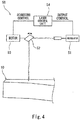
- Fig. 4 is a block diagram of a laser device 50 configured to irradiate the plate spring 10 with a laser beam.
- the laser device 50 includes a laser oscillator 51, a mirror 52, a motor 53, and a laser control unit 54 and irradiates the plate spring 10 with the laser beam.
- the laser oscillator 51 generates and outputs the laser beam.
- the mirror 52 (galvanometer mirror, for example) reflects the laser beam, output from the laser oscillator 51, toward a target position of the plate spring 10.
- the motor 53 drives the mirror 52 to adjust an angle of the mirror 52 and thereby adjust a reflection direction of the laser beam.
- the laser control unit 54 controls the laser oscillator 51 to control intensity of the laser beam (output control).
- the laser control unit 54 controls the motor 53 to control a scanning direction and scanning speed of the laser beam (scanning control).
- Figs. 5A to 5C are diagrams for explaining a procedure of providing the electrode pair E 1F at the plate spring 10.
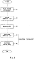
- Fig. 6 is a flow chart for explaining the procedure of providing the electrode pair E 1F at the plate spring 10.
- the plate spring 10 is fixed to a jig (not shown), and the plate spring 10 is positioned relative to the laser device 50 (Step S1: plate spring fixing step).
- Step S1 plate spring fixing step.
- Step S2 resin removing step
- the exposed region X is formed only on the side end surface of the first fiber-reinforced resin layer 31.
- the exposed region X is formed in a rectangular shape in a side view of the plate spring 10.
- the resin has the light transmission property
- the carbon fibers have the light absorption property. Therefore, in the resin removing step, the carbon fibers absorb the laser beam L1, having passed through the resin, to generate heat, so that the resin around the heat-generating carbon fibers can be removed by the heat. On this account, the irradiation of the laser beam L1 does not have to avoid the carbon fibers. Thus, the irradiation of the laser beam L1 can be simplified, and the producibility improves.
- the laser beam L1 scans in an extending direction of the carbon fibers (i.e., in the longitudinal direction of the plate spring 10).
- the resin can be removed by quickly increasing the temperatures of the individual carbon fibers, and heat load can be prevented from being repeatedly applied to the individual carbon fibers and thereby the carbon fibers can be prevented from deteriorating (for example, from being cut).
- Step S3 washing step
- thermosetting electrically conductive inks 141, 142, and 143 are applied to the washed exposed region X by screen printing (Step S4: electrode applying step).
- Step S4 electrode applying step
- an electrode forming step includes the electrode applying step and the electrode curing step. Since the laser beam L2 of the laser device 50 is used also in the electrode curing step, it is unnecessary to use a thermostatic tank or the like, and therefore, equipment can be simplified. Further, since the common laser device 50 is used in both the resin removing step and the electrode curing step, the work efficiency improves, and the cost can be reduced.
- the laser control unit 54 controls the laser oscillator 51 and the motor 53 such that energy per unit area of the laser beam L2 with which the electrically conductive inks 141, 142, and 143 are irradiated in the electrode curing step is smaller than energy per unit area of the laser beam L1 with which the side end surface of the first fiber-reinforced resin layer 31 is irradiated in the resin removing step.
- the laser control unit 54 controls the laser oscillator 51 such that a laser output in the electrode curing step is lower than a laser output in the resin removing step.
- the laser control unit 54 controls the motor 53 such that a laser scanning speed in the electrode curing step is higher than a laser scanning speed in the resin removing step.
- the energy per unit area of the laser beam L2 used in the electrode curing step is set to such energy that even when the laser beam L2 contacts the carbon fiber, and the carbon fiber increases in temperature, the temperature of the carbon fiber does not reach the thermal decomposition temperature of the carbon fiber. Therefore, in the electrode curing step, the laser beam L2 may contact the resin outside the electrically conductive inks 141, 142, and 143. Thus, the work in the electrode curing step can be simplified.
- the electrode pairs E 0 , E 1F , E 2F , E 1R , and E 2R which do not vary can be easily formed and can be stably brought into electrically conductive contact with the carbon fibers. Therefore, the electrode-equipped plate spring 10 mounted on the railcar bogie and made of the fiber-reinforced resin can be produced with stable quality.
- the electrode forming step includes the electrode applying step and the electrode curing step.
- the electrode may be formed at the plate spring by plating.
- resin having the light absorption property may be used as the resin of the fiber-reinforced resin to which the electrode is attached.
- the carbon fibers may be exposed by removing the light-absorbing resin by the thermal decomposition caused by the laser beam.
- a coloring agent for example, epoxy resin
- the resin is made nontransparent and colored
- the resin absorbs the laser beam to be thermally decomposed.
Landscapes
- Engineering & Computer Science (AREA)
- Mechanical Engineering (AREA)
- Physics & Mathematics (AREA)
- Chemical & Material Sciences (AREA)
- General Engineering & Computer Science (AREA)
- Optics & Photonics (AREA)
- Life Sciences & Earth Sciences (AREA)
- Health & Medical Sciences (AREA)
- Electrochemistry (AREA)
- Analytical Chemistry (AREA)
- Biochemistry (AREA)
- General Health & Medical Sciences (AREA)
- General Physics & Mathematics (AREA)
- Immunology (AREA)
- Pathology (AREA)
- Chemical Kinetics & Catalysis (AREA)
- Plasma & Fusion (AREA)
- Springs (AREA)
- Investigating Or Analyzing Materials By The Use Of Electric Means (AREA)
Abstract
Description
- The present invention relates to a method of producing an electrode-equipped plate spring of a railcar bogie, and particularly to a method of producing a plate spring to which an electrode for realizing monitoring of a state of the plate spring is attached.
- Proposed is a railcar bogie from which side sills are omitted in such a manner that: each of plate springs extends between front and rear axle boxes; and longitudinal direction middle portions of the plate springs support a cross beam (see PTL 1). To be specific, in this bogie, the plate spring achieves the function of a suspension and the function of a conventional side sill. To reduce the weight of the bogie, the plate springs are formed by using fiber-reinforced resin.
- While the bogie is traveling, loads are repeatedly applied to the plate springs. Therefore, regarding the plate springs that have been used for a long period of time, attention to strength deterioration by fatigue is necessary. Here, realizing simple monitoring of the state of the plate spring itself is useful for an improvement of maintenance efficiency of the bogie. For example,
PTL 2 discloses a technique in which: a plurality of electrodes are arranged at predetermined intervals on one of surfaces of a composite material made of CFRP; and abnormality of the composite material is detected from a change in electrical resistance measured based on current flowing between the electrodes. -
- PTL 1: Japanese Patent No.
5438796 - PTL 2: Japanese Laid-Open Patent Application Publication No.
2001-318070 - When providing the electrode on the surface of the CFRP, carbon fibers having electrical conductivity are exposed by removing resin of the surface of the CFRP, and the electrode is then attached. In this case, if work of scraping the resin by polishing is inadequate, unnecessary resin remains, and electrical conduction between the electrode and the carbon fibers becomes incomplete. In contrast, if the resin is scraped too much, the carbon fibers are cut, and a contact state between the electrode and the carbon fibers easily changes. Thus, measured values vary.
- An object of the present invention is to maintain stable quality of a fiber-reinforced resin plate spring for use in a railcar bogie by, when attaching an electrode to the plate spring, stably bringing the electrode into electrically conductive contact with electrically conductive fibers.
- A method of producing an electrode-equipped plate spring of a railcar bogie according to one aspect of the present invention includes: a resin removing step of partially irradiating a surface of fiber-reinforced resin, prepared by including electrically conductive fibers in resin, of a plate spring with a laser beam to partially remove the resin and partially expose the electrically conductive fibers; and an electrode forming step of attaching an electrode to an exposed region formed by partially exposing the electrically conductive fibers of the fiber-reinforced resin.
- According to the above method, the electrically conductive fibers are partially exposed by partially removing the resin using the laser beam. Therefore, by managing the output of the laser beam and the like, the exposed region of the fiber-reinforced resin can be stably and accurately formed, and individual variations can be reduced. Then, by attaching the electrode to the exposed region of the fiber-reinforced resin, the electrode can be stably brought into electrically conductive contact with the electrically conductive fibers, and variations in measured values can be reduced. Therefore, the quality of the electrode-equipped plate spring made of the fiber-reinforced resin can be stabilized.
- According to the present invention, stable quality of a fiber-reinforced resin plate spring for use in a railcar bogie can be maintained by, when attaching an electrode to the plate spring, stably bringing the electrode into electrically conductive contact with electrically conductive fibers.
-
-
Fig. 1 is a side view of a railcar bogie including an electrode-equipped plate spring according to an embodiment. -
Fig. 2 is a sectional view when viewed from a longitudinal direction of the plate spring shown inFig. 1 . -
Fig. 3 is a conceptual diagram for explaining a principle of monitoring a state of the plate spring shown inFig. 1 . -
Fig. 4 is a block diagram of a laser device configured to irradiate the plate spring with a laser beam. -
Figs. 5A to 5C are diagrams for explaining a procedure of providing an electrode at the plate spring. -
Fig. 6 is a flow chart for explaining the procedure of providing the electrode at the plate spring. - Hereinafter, an embodiment will be explained in reference to the drawings. In the following explanations, a direction in which a railcar travels and in which a carbody extends is defined as a car longitudinal direction, and a crosswise direction perpendicular to the car longitudinal direction is defined as a car width direction. The car longitudinal direction is also referred to as a forward/rearward direction, and the car width direction is also referred to as a leftward/rightward direction. To be specific, the railcar can travel in both directions along the car longitudinal direction, but if the railcar travels in one direction, this traveling direction may be referred to as a forward direction, and a direction opposite to the traveling direction may be referred to as a rearward direction.
-
Fig. 1 is a side view of arailcar bogie 1 including an electrode-equippedplate spring 10 according to the embodiment. As shown inFig. 1 , thebogie 1 includes abogie frame 3 supporting acarbody 20 throughair springs 2 that are secondary suspensions. Thebogie frame 3 includes across beam 3a extending in the car width direction but does not include side sills extending from both respective car width direction end portions of thecross beam 3a in the car longitudinal direction. Theair springs 2 are provided on an upper surface of thecross beam 3a.Axles cross beam 3a.Wheels 6 are fixed to both respective car width direction sides of theaxle 4, andwheels 7 are fixed to both respective car width direction sides of theaxle 5. -
Bearings 8 rotatably supporting theaxle 4 are provided at both respective car width direction end portions of theaxle 4 so as to be located outside therespective wheels 6 in the car width direction, and thebearings 8 are accommodated inrespective axle boxes 11. Similarly,bearings 9 rotatably supporting theaxle 5 are provided at both respective car width direction end portions of theaxle 5 so as to be located outside therespective wheels 7 in the car width direction, and thebearings 9 are accommodated inrespective axle boxes 12. Each of the car width direction end portions of thecross beam 3a is coupled to theaxle box 11 by an axle beamtype coupling mechanism 13 and also coupled to theaxle box 12 by an axle beamtype coupling mechanism 14. Each of the electrode-equippedplate springs 10 extending in the car longitudinal direction is provided between thecross beam 3a and theaxle box 11 and between thecross beam 3a and theaxle box 12. Longitudinaldirection middle portions 10a of theplate springs 10 elastically support the respective car width direction end portions of thecross beam 3a from below. A longitudinaldirection end portion 10b of theplate spring 10 is supported by theaxle box 11, and a longitudinaldirection end portion 10c of theplate spring 10 is supported by theaxle box 12. To be specific, theplate spring 10 achieves the function of a primary suspension and the function of a conventional side sill. - Pressing
members 17 each having a circular-arclower surface 17a are provided at respective lower portions of the car width direction end portions of thecross beam 3a. Each of thepressing members 17 is placed on themiddle portion 10a of theplate spring 10 from above and contacts themiddle portion 10a so as to be separable from themiddle portion 10a. To be specific, the pressingmember 17 contacts an upper surface of theplate spring 10 and presses the upper surface from above by a downward load, applied from thecross beam 3a by gravity, so as not to fix theplate spring 10 in an upward/downward direction relative to the pressingmember 17. Further, supportingmembers axle boxes end portion 10b of theplate spring 10 is supported by theaxle box 11 from below through the supportingmember 15, and theend portion 10c of theplate spring 10 is supported by theaxle box 12 from below through the supportingmember 16. Upper surfaces of the supportingmembers end portion 10b of theplate spring 10 is placed on the supportingmember 15 from above, and theend portion 10c of theplate spring 10 is placed on the supportingmember 16 from above. - By this configuration, the load from the
carbody 20 is transmitted to the middle portions of theplate springs 10 through the pressingmembers 17 provided at the respective lower portions of the car width direction end portions of thecross beam 3a. Further, when a height difference between the front andrear wheels plate spring 10 rotates relative to the pressingmember 17 like a seesaw to prevent a decrease of a wheel load. As above, while the bogie is traveling, loads are repeatedly applied to theplate springs 10. - An
intermediate portion 10d that is an intermediate region between themiddle portion 10a and theend portion 10b in theplate spring 10 and anintermediate portion 10e that is an intermediate region between themiddle portion 10a and theend portion 10c in theplate spring 10 are separated from other members and arranged in a free state in the air. To be specific, deformation and displacement of theintermediate portions 10d are 10e are not restricted. Therefore, according to theplate spring 10, theintermediate portions middle portion 10a and theend portions intermediate portions plate spring 10 are inclined downward toward themiddle portion 10a, and themiddle portion 10a of theplate spring 10 is located lower than theend portions plate spring 10. To be specific, in a side view, theplate spring 10 is formed in a bow shape that is convex downward as a whole. Theplate spring 10 has such a shape that the thickness thereof gradually decreases from themiddle portion 10a toward each of theend portions Fig. 1 is defined as a traveling direction. Thewheel 6 is referred to as a front wheel, and thewheel 7 is referred to as a rear wheel. - Each of electrode pairs E0, E1F, E2F, E1R, and E2R is provided on both width direction side end surfaces 10f of the
plate spring 10, a width direction being perpendicular to the longitudinal direction and thickness direction of theplate spring 10. Each of the electrode pairs E0, E1F, E2F, E1R, and E2R sandwiches theplate spring 10 in the width direction. When viewed from themiddle portion 10a of theplate spring 10, the electrode pairs E0, E1F, and E2F are arranged close to thefront wheel 6, and the electrode pairs E1R and E2R are arranged close to therear wheel 7. A set of the electrode pairs E1F and E2F and a set of the electrode pairs E1R and E2R are arranged symmetrically with respect to a longitudinal direction center of theplate spring 10. Amonitoring control unit 19 electrically connected to the electrode pairs E0, E1F, E2F, E1R, and E2R through electric wires is mounted on thebogie frame 3. Astate monitoring device 30 includes the plate springs 10, the electrode pairs E0, E1F, E2F, E1R, and E2R, and themonitoring control unit 19. It should be noted that the configurations of the electrode pairs E0, E1F, E2F, E1R, and E2R themselves are the same as one another, and methods of forming the electrode pairs E0, E1F, E2F, E1R, and E2R themselves are the same as one another. Therefore, the following will mainly explain the electrode pair E1F. -
Fig. 2 is a sectional view when viewed from the longitudinal direction of theplate spring 10 shown inFig. 1 .Fig. 3 is a conceptual diagram for explaining a principle of monitoring a state of theplate spring 10 shown inFig. 1 . As shown inFigs. 2 and 3 , theplate spring 10 is formed by laminating a plurality of fiber-reinforced resin layers and is molded by using a typical composite material molding technique, such as autoclave molding. In the present embodiment, theplate spring 10 includes a first fiber-reinforcedresin layer 31, a second fiber-reinforcedresin layer 32, a third fiber-reinforced resin layer 33, and a fourth fiber-reinforcedresin layer 34. The first fiber-reinforcedresin layer 31, the second fiber-reinforcedresin layer 32, the third fiber-reinforced resin layer 33, and the fourth fiber-reinforcedresin layer 34 are provided in this order from an upper side to a lower side. The third fiber-reinforced resin layer 33 is formed such that the thickness thereof gradually decreases from a longitudinal direction middle portion thereof to each of end portions thereof. The thickness of the first fiber-reinforcedresin layer 31, the thickness of the second fiber-reinforcedresin layer 32, and the thickness of the fourth fiber-reinforcedresin layer 34 are constant. - The first fiber-reinforced
resin layer 31, the second fiber-reinforcedresin layer 32, and the fourth fiber-reinforcedresin layer 34 contain fibers having electrical conductivity. In the present embodiment, fiber-reinforced resin of the first fiber-reinforcedresin layer 31, the second fiber-reinforcedresin layer 32, and the fourth fiber-reinforcedresin layer 34 includes resin having a light transmission property and electrically conductive fibers having a light absorption property. In the fiber-reinforced resin of the fiber-reinforced resin layers 31, 32, and 34, a thermal decomposition temperature of the resin is lower than a thermal decomposition temperature of the electrically conductive fibers. The electrically conductive fibers of the fiber-reinforced resin of the fiber-reinforced resin layers 31, 32, and 34 are nontransparent and have a non-reflective property. As one example, in the fiber-reinforced resin of the fiber-reinforced resin layers 31, 32, and 34, the electrically conductive fibers are black carbon fibers, and the resin is epoxy resin that transmits light. To be specific, the first fiber-reinforcedresin layer 31, the second fiber-reinforcedresin layer 32, and the fourth fiber-reinforcedresin layer 34 are formed by CFRP containing continuous carbon fibers. - The first fiber-reinforced
resin layer 31 and the fourth fiber-reinforcedresin layer 34 contain carbon fibers continuously extending from one longitudinal direction end of theplate spring 10 to the other longitudinal direction end of theplate spring 10 when viewed from a normal direction of a main surface (an upper surface or a lower surface) of theplate spring 10. To be specific, each of the first fiber-reinforcedresin layer 31 and the fourth fiber-reinforcedresin layer 34 mainly includes a unidirectional material as a laminate component, the unidirectional material being a material in which carbon fibers are oriented in one direction along the longitudinal direction of theplate spring 10. The second fiber-reinforcedresin layer 32 includes a material containing carbon fibers that are continuous from one width direction end of theplate spring 10 to the other width direction end of theplate spring 10 when viewed from the normal direction of the main surface (the upper surface or the lower surface) of theplate spring 10. To be specific, the second fiber-reinforcedresin layer 32 mainly includes, for example, a unidirectional material or a textile material as a laminate component, the unidirectional material being a material in which carbon fibers are oriented in one direction along the width direction of theplate spring 10, the textile material being a material in which carbon fibers are oriented in lengthwise and crosswise directions. The third fiber-reinforced resin layer 33 is formed by FRP containing electrically nonconductive reinforced fibers. As one example, the third fiber-reinforced resin layer 33 is formed by GFRP containing glass fibers. - As described above, the first fiber-reinforced
resin layer 31, the second fiber-reinforcedresin layer 32, and the fourth fiber-reinforcedresin layer 34 contain the electrically conductive fibers, and the third fiber-reinforced resin layer 33 does not contain the electrically conductive fibers but contains the electrically nonconductive fibers. To be specific, a boundary between layers containing electrically conductive fibers is a boundary between the first fiber-reinforcedresin layer 31 and the second fiber-reinforcedresin layer 32. The electrode pair E1F is directly attached to both width direction side end surfaces of the first fiber-reinforcedresin layer 31. Specifically, after the carbon fibers are partially exposed by removing the resin at predetermined portions on both width direction side end surfaces of the first fiber-reinforcedresin layer 31, the electrode pair E1F is attached to these portions. In the present embodiment, the electrode pair E1F is located away from the second fiber-reinforcedresin layer 32. - As electrically conductive paths of current flowing through the electrode pair E1F, there are a first electrically conductive path P1 and a second electrically conductive path P2 as schematically shown by thick arrows in
Fig. 2 . The first electrically conductive path P1 is formed only by the carbon fibers of the first fiber-reinforcedresin layer 31, and the second electrically conductive path P2 is formed so as to extend through both the carbon fibers of the first fiber-reinforcedresin layer 31 and the carbon fibers of the second fiber-reinforcedresin layer 32. The first fiber-reinforcedresin layer 31 is the unidirectional material and hardly contains continuous fibers continuously extending from one width direction end to the other width direction end. Therefore, the first electrically conductive path P1 is formed in such a manner that a large number of carbon fibers of the first fiber-reinforcedresin layer 31 are provided adjacent to one another and contact one another. On this account, the first electrically conductive path P1 has an irregular route extending in the longitudinal direction and width direction of theplate spring 10. - The second electrically conductive path P2 is formed by the carbon fibers of one width direction end portion of the first fiber-reinforced
resin layer 31, the carbon fibers of the second fiber-reinforcedresin layer 32, and the carbon fibers of the other width direction end portion of the first fiber-reinforcedresin layer 31. To be specific, the second electrically conductive path P2 extends through the boundary between the first fiber-reinforcedresin layer 31 and the second fiber-reinforcedresin layer 32 by the contact between the carbon fibers of the first fiber-reinforcedresin layer 31 and the carbon fibers of the second fiber-reinforcedresin layer 32. The carbon fibers of the second fiber-reinforcedresin layer 32 contains continuous fibers continuously extending from one width direction end of theplate spring 10 to the other width direction end of theplate spring 10. Therefore, the current can flow in the width direction of theplate spring 10 through the electrically conductive path of the second fiber-reinforcedresin layer 32 which path is shorter in distance than the electrically conductive path of the first fiber-reinforcedresin layer 31. On this account, electrical resistance of the second fiber-reinforcedresin layer 32 to the current flowing in the width direction is smaller than electrical resistance of the first fiber-reinforcedresin layer 31 to the current flowing in the width direction. Thus, when the current flows through the electrode pair E1F, the current flowing through the second electrically conductive path P2 is larger than the current flowing through the first electrically conductive path P1. - As above, the second electrically conductive path P2 through which a large amount of current flows extends through the boundary between the first fiber-reinforced
resin layer 31 and the second fiber-reinforcedresin layer 32. Therefore, if the delamination occurs between the first fiber-reinforcedresin layer 31 and the second fiber-reinforcedresin layer 32, a sectional area of the second electrically conductive path P2 decreases, so that the electrical resistance of the second electrically conductive path P2 significantly changes. On this account, when a resistance value of theplate spring 10 which value is obtained by supplying the current to the electrode pair E1F significantly increases, it can be determined that the delamination has occurred. Further, regarding the first electrically conductive path PI, if the delamination occurs in the first fiber-reinforcedresin layer 31, that is, the adjacent fibers contacting each other in the first fiber-reinforcedresin layer 31 are separated from each other, a sectional area of the first electrically conductive path P1 decreases, so that the electrical resistance of the first electrically conductive path P1 changes. On this account, this delamination can also be detected by monitoring the increase in the resistance value of theplate spring 10, the resistance value being obtained by supplying the current to the electrode pair E1F. - The electrode pair E1F is constituted by: a middle
electrode element pair 41 for voltage measurement; and side electrode element pairs 42 and 43 for power supply, thepairs electrode element pair 41 in the longitudinal direction of theplate spring 10 so as to be spaced apart from the middleelectrode element pair 41. Each of the electrode element pairs 41 to 43 is formed in such a shape as to extend in a thickness direction of the first fiber-reinforcedresin layer 31. The side electrode element pairs 42 and 43 are short-circuited to each other and connected to a circuit including apower supply 45 and acurrent sensor 46. Thepower supply 45 supplies constant current I to the side electrode element pairs 42 and 43. The middleelectrode element pair 41 is connected to a circuit including avoltage sensor 47. To be specific, thevoltage sensor 47 detects a voltage of the middleelectrode element pair 41. Thestate monitoring device 30 includes: thepower supply 45 configured to supply the constant current to the side electrode element pairs 42 and 43; and thevoltage sensor 47 configured to detect the voltage of the middleelectrode element pair 41. Distribution (shown by broken lines inFig. 3 ) of the current supplied to each of the side electrode element pairs 42 and 43 spreads to some extent in the longitudinal direction of theplate spring 10. Therefore, the current concentrates on a portion of theplate spring 10, the portion being sandwiched by the middleelectrode element pair 41. Therefore, a change in the voltage of the middleelectrode element pair 41 is stably detected by thevoltage sensor 47. -
Fig. 4 is a block diagram of alaser device 50 configured to irradiate theplate spring 10 with a laser beam. As shown inFig. 4 , thelaser device 50 includes alaser oscillator 51, amirror 52, amotor 53, and alaser control unit 54 and irradiates theplate spring 10 with the laser beam. Thelaser oscillator 51 generates and outputs the laser beam. The mirror 52 (galvanometer mirror, for example) reflects the laser beam, output from thelaser oscillator 51, toward a target position of theplate spring 10. Themotor 53 drives themirror 52 to adjust an angle of themirror 52 and thereby adjust a reflection direction of the laser beam. Thelaser control unit 54 controls thelaser oscillator 51 to control intensity of the laser beam (output control). Thelaser control unit 54 controls themotor 53 to control a scanning direction and scanning speed of the laser beam (scanning control). -
Figs. 5A to 5C are diagrams for explaining a procedure of providing the electrode pair E1F at theplate spring 10.Fig. 6 is a flow chart for explaining the procedure of providing the electrode pair E1F at theplate spring 10. As shown inFig. 6 , first, theplate spring 10 is fixed to a jig (not shown), and theplate spring 10 is positioned relative to the laser device 50 (Step S1: plate spring fixing step). Next, as shown inFigs. 5A and6 , by irradiating a target portion of the side end surface of the first fiber-reinforcedresin layer 31 of theplate spring 10 with a laser beam L1, the resin on the surface of the target portion is removed, and thus, an exposed region X formed by partially exposing the carbon fibers is formed (Step S2: resin removing step). In the present embodiment, the exposed region X is formed only on the side end surface of the first fiber-reinforcedresin layer 31. As one example, the exposed region X is formed in a rectangular shape in a side view of theplate spring 10. When forming the exposed region X using the laser beam L1, the output and scanning speed of the laser beam L1 of thelaser device 50 are managed by thelaser control unit 54. With this, the exposed region X of the fiber-reinforced resin can be stably and accurately formed, and individual variations are reduced. - In the first fiber-reinforced
resin layer 31 of theplate spring 10, the resin has the light transmission property, and the carbon fibers have the light absorption property. Therefore, in the resin removing step, the carbon fibers absorb the laser beam L1, having passed through the resin, to generate heat, so that the resin around the heat-generating carbon fibers can be removed by the heat. On this account, the irradiation of the laser beam L1 does not have to avoid the carbon fibers. Thus, the irradiation of the laser beam L1 can be simplified, and the producibility improves. - In the resin removing step, when viewed from an irradiation direction of the laser beam L1 (i.e., in a side view of the plate spring 10), the laser beam L1 scans in an extending direction of the carbon fibers (i.e., in the longitudinal direction of the plate spring 10). With this, as compared to a case where the laser beam scans in a direction perpendicular to the extending direction of the carbon fiber (i.e., in the thickness direction of the plate spring 10) when viewed from the irradiation direction of the laser beam L1, the resin can be removed by quickly increasing the temperatures of the individual carbon fibers, and heat load can be prevented from being repeatedly applied to the individual carbon fibers and thereby the carbon fibers can be prevented from deteriorating (for example, from being cut).
- Next, the exposed region X of the side end surface of the first fiber-reinforced
resin layer 31 of theplate spring 10 is washed using a cleaning liquid (for example, acetone) for subsequent steps (Step S3: washing step). Next, as shown inFigs. 5B and6 , thermosetting electricallyconductive inks Figs. 5C and6 , thelaser device 50 irradiates the applied electricallyconductive inks conductive inks laser device 50 is used also in the electrode curing step, it is unnecessary to use a thermostatic tank or the like, and therefore, equipment can be simplified. Further, since thecommon laser device 50 is used in both the resin removing step and the electrode curing step, the work efficiency improves, and the cost can be reduced. - Further, in this case, the
laser control unit 54 controls thelaser oscillator 51 and themotor 53 such that energy per unit area of the laser beam L2 with which the electricallyconductive inks resin layer 31 is irradiated in the resin removing step. Specifically, thelaser control unit 54 controls thelaser oscillator 51 such that a laser output in the electrode curing step is lower than a laser output in the resin removing step. Further, according to need, thelaser control unit 54 controls themotor 53 such that a laser scanning speed in the electrode curing step is higher than a laser scanning speed in the resin removing step. For example, the energy per unit area of the laser beam L2 used in the electrode curing step is set to such energy that even when the laser beam L2 contacts the carbon fiber, and the carbon fiber increases in temperature, the temperature of the carbon fiber does not reach the thermal decomposition temperature of the carbon fiber. Therefore, in the electrode curing step, the laser beam L2 may contact the resin outside the electricallyconductive inks - According to the producing method explained above, without deteriorating the fiber-reinforced resin of the
plate spring 10, the electrode pairs E0, E1F, E2F, E1R, and E2R which do not vary can be easily formed and can be stably brought into electrically conductive contact with the carbon fibers. Therefore, the electrode-equippedplate spring 10 mounted on the railcar bogie and made of the fiber-reinforced resin can be produced with stable quality. - The present invention is not limited to the above-described embodiment, and modifications, additions, and eliminations may be made with respect to the configuration of the present invention. In the present embodiment, the electrode forming step includes the electrode applying step and the electrode curing step. However, for example, in the electrode forming step, the electrode may be formed at the plate spring by plating. Further, resin having the light absorption property may be used as the resin of the fiber-reinforced resin to which the electrode is attached. To be specific, the carbon fibers may be exposed by removing the light-absorbing resin by the thermal decomposition caused by the laser beam. One example is that: by adding a coloring agent to transparent resin (for example, epoxy resin), the resin is made nontransparent and colored; and the resin absorbs the laser beam to be thermally decomposed.
-
- 1 bogie
- 10 plate spring
- 50 laser device
- 141 to 143 electrically conductive ink (electrically conductive material)
- E0, E1F, E2F, E1R, E2R electrode pair
- X exposed region
Claims (8)
- A method of producing an electrode-equipped plate spring of a railcar bogie,
the method comprising:a resin removing step of partially irradiating a surface of fiber-reinforced resin, prepared by including electrically conductive fibers in resin, of a plate spring with a laser beam to partially remove the resin and partially expose the electrically conductive fibers; andan electrode forming step of attaching an electrode to an exposed region formed by partially exposing the electrically conductive fibers of the fiber-reinforced resin. - The method according to claim 1, wherein the resin has a light transmission property, and the electrically conductive fibers have a light absorption property.
- The method according to claim 1, wherein the resin has a light absorption property.
- The method according to claim 2 or 3, wherein in the resin removing step, the laser beam scans in an extending direction of the electrically conductive fibers when viewed from an irradiation direction of the laser beam.
- The method according to any one of claims 1 to 4, wherein in the electrode forming step, the electrode is formed in such a manner that: a thermosetting electrically conductive material is applied to the exposed region; and the electrically conductive material is irradiated with the laser beam to be cured.
- The method according to claim 5, wherein the common laser device for irradiation of the laser beam is used in the resin removing step and the electrode forming step.
- The method according to claim 5 or 6, wherein energy per unit area of the laser beam with which the electrically conductive material is irradiated in the electrode forming step is smaller than energy per unit area of the laser beam with which the fiber-reinforced resin is irradiated in the resin removing step.
- The method according to any one of claims 1 to 7, wherein in the electrode forming step, one middle electrode pair and two side electrode element pairs are formed at one of longitudinal direction sides of the plate spring and at the exposed region formed on both side surfaces of the plate spring, the two side electrode element pairs being arranged at both respective sides of the middle electrode pair in a longitudinal direction of the plate spring so as to be spaced apart from the middle electrode pair.
Applications Claiming Priority (2)
| Application Number | Priority Date | Filing Date | Title |
|---|---|---|---|
| JP2015178072A JP6510938B2 (en) | 2015-09-10 | 2015-09-10 | Method of manufacturing an electroded plate spring of a bogie for a railway vehicle |
| PCT/JP2016/004078 WO2017043079A1 (en) | 2015-09-10 | 2016-09-07 | Methof for manufacturing leafspring with electrodes for railcar truck |
Publications (3)
| Publication Number | Publication Date |
|---|---|
| EP3348448A1 true EP3348448A1 (en) | 2018-07-18 |
| EP3348448A4 EP3348448A4 (en) | 2019-05-08 |
| EP3348448B1 EP3348448B1 (en) | 2021-04-14 |
Family
ID=58239396
Family Applications (1)
| Application Number | Title | Priority Date | Filing Date |
|---|---|---|---|
| EP16843946.1A Active EP3348448B1 (en) | 2015-09-10 | 2016-09-07 | Method for manufacturing leafspring with electrodes for railcar truck |
Country Status (8)
| Country | Link |
|---|---|
| US (1) | US10703394B2 (en) |
| EP (1) | EP3348448B1 (en) |
| JP (1) | JP6510938B2 (en) |
| KR (1) | KR102023683B1 (en) |
| CN (1) | CN107921974B (en) |
| SG (1) | SG11201801868YA (en) |
| TW (1) | TWI603876B (en) |
| WO (1) | WO2017043079A1 (en) |
Families Citing this family (4)
| Publication number | Priority date | Publication date | Assignee | Title |
|---|---|---|---|---|
| JP6510938B2 (en) * | 2015-09-10 | 2019-05-08 | 川崎重工業株式会社 | Method of manufacturing an electroded plate spring of a bogie for a railway vehicle |
| CN111468828B (en) * | 2020-04-10 | 2022-08-30 | Oppo(重庆)智能科技有限公司 | Welding equipment and welding detection method |
| US20230127791A1 (en) * | 2021-10-22 | 2023-04-27 | Embry-Riddle Aeronautical University, Inc. | Laser machining and related control for additive manufacturing |
| JP7728022B2 (en) * | 2023-05-19 | 2025-08-22 | Todo Meta Composites合同会社 | Short fiber multiphase reinforced thermoplastic resin structure with different fiber content, bonded body thereof, and manufacturing method |
Family Cites Families (37)
| Publication number | Priority date | Publication date | Assignee | Title |
|---|---|---|---|---|
| JPS5438796A (en) | 1977-09-01 | 1979-03-23 | Seiko Epson Corp | Liquid crystal display device |
| JP3141125B2 (en) * | 1992-08-26 | 2001-03-05 | 日立マクセル株式会社 | Tape cartridge |
| JPH0647745U (en) * | 1992-12-02 | 1994-06-28 | 日野自動車工業株式会社 | Damage detection device for leaf spring made of fiber reinforced resin |
| FR2780016B1 (en) | 1998-06-18 | 2000-08-04 | Alsthom Gec | RAIL VEHICLE BOGIE AND METHOD FOR MANUFACTURING A SIDING OF SUCH BOGIE |
| US6660114B2 (en) * | 2000-01-24 | 2003-12-09 | Pacific Coast Composites | Method for producing a hybrid leaf spring |
| US6461455B1 (en) * | 2000-01-24 | 2002-10-08 | Pacific Coast Composites | Method of producing a hybrid leaf spring |
| JP2001318070A (en) | 2000-05-02 | 2001-11-16 | Rikogaku Shinkokai | Composite material peeling detection apparatus and peeling detection method |
| JP4583576B2 (en) * | 2000-10-19 | 2010-11-17 | 富士重工業株式会社 | Damage position detection device for fiber reinforced resin composite and method for manufacturing damage detection sensor |
| CN1187761C (en) * | 2003-08-22 | 2005-02-02 | 武汉理工大学 | Self diagnostic intellgient structure of fiber reinforced resin base composite material and method for self diagnosis |
| US7291271B2 (en) * | 2003-12-09 | 2007-11-06 | Separation Design Group, Llc | Meso-frequency traveling wave electro-kinetic continuous adsorption system |
| US8116341B2 (en) | 2007-05-31 | 2012-02-14 | Electro Scientific Industries, Inc. | Multiple laser wavelength and pulse width process drilling |
| JP4946659B2 (en) * | 2007-06-26 | 2012-06-06 | 横浜ゴム株式会社 | Abnormality detection method for fiber reinforced plastic panel and fiber reinforced base material used in this abnormality detection method |
| CN101803008B (en) | 2007-09-07 | 2012-11-28 | 株式会社半导体能源研究所 | Semiconductor device and method for manufacturing the same |
| KR101469406B1 (en) * | 2011-07-14 | 2014-12-04 | 카와사키 주코교 카부시키 카이샤 | Railway vehicle truck |
| JP5947590B2 (en) * | 2011-07-14 | 2016-07-06 | 川崎重工業株式会社 | Railcar bogie |
| CN103796899B (en) * | 2011-09-15 | 2016-05-18 | 株式会社Gh工艺 | Leaf springs for railway vehicle bogies |
| JP5878791B2 (en) * | 2012-02-29 | 2016-03-08 | 川崎重工業株式会社 | Leaf spring unit and bogie for railway vehicles using the same |
| US9868179B2 (en) | 2012-03-09 | 2018-01-16 | TOYOKOH, Co., Ltd. | Laser irradiation device, laser irradiation system, and method for removing coating or adhering matter |
| US9352757B2 (en) * | 2012-04-06 | 2016-05-31 | Kawasaki Jukogyo Kabushiki Kaisha | Railcar bogie |
| JP5438796B2 (en) * | 2012-04-06 | 2014-03-12 | 川崎重工業株式会社 | Railway vehicle carriage and railway vehicle equipped with the same |
| CN103839321B (en) * | 2012-11-23 | 2018-05-15 | 北京嘉岳同乐极电子有限公司 | A kind of long size detection Magnetic Sensor and preparation method thereof |
| JP5878992B2 (en) * | 2013-01-10 | 2016-03-08 | 川崎重工業株式会社 | Railcar bogie |
| JP6110669B2 (en) * | 2013-01-10 | 2017-04-05 | 川崎重工業株式会社 | Railway vehicle carriage and railway vehicle equipped with the same |
| JP6068984B2 (en) * | 2013-01-10 | 2017-01-25 | 川崎重工業株式会社 | Railcar bogie |
| JP6190148B2 (en) * | 2013-04-24 | 2017-08-30 | 川崎重工業株式会社 | Railcar bogie |
| JP6273096B2 (en) * | 2013-04-24 | 2018-01-31 | 川崎重工業株式会社 | Railcar bogie |
| JP2015000434A (en) | 2013-06-13 | 2015-01-05 | 株式会社最新レーザ技術研究センター | Laser processing method using beam branching synthesis optical system |
| JP6088366B2 (en) * | 2013-06-19 | 2017-03-01 | 川崎重工業株式会社 | Leaf spring cover and railcar bogie equipped with the same |
| JP6247494B2 (en) * | 2013-10-09 | 2017-12-13 | 川崎重工業株式会社 | Method for manufacturing leaf spring for railway vehicle bogie |
| JP6506564B2 (en) * | 2015-02-04 | 2019-04-24 | 川崎重工業株式会社 | Condition monitoring device of leaf spring of bogie for railway vehicle |
| JP6506630B2 (en) * | 2015-06-03 | 2019-04-24 | 川崎重工業株式会社 | Leaf spring unit and truck for railway vehicle |
| JP6510938B2 (en) * | 2015-09-10 | 2019-05-08 | 川崎重工業株式会社 | Method of manufacturing an electroded plate spring of a bogie for a railway vehicle |
| JP6944765B2 (en) * | 2016-05-16 | 2021-10-06 | 川崎重工業株式会社 | Assembling method of railroad car bogie, measuring jig and railroad car bogie |
| JP6761331B2 (en) * | 2016-12-07 | 2020-09-23 | 川崎重工業株式会社 | Ultrasonic flaw detectors and methods for composite materials |
| JP6726612B2 (en) * | 2016-12-16 | 2020-07-22 | 川崎重工業株式会社 | Railcar bogie |
| CN110198880A (en) * | 2017-01-30 | 2019-09-03 | 川崎重工业株式会社 | bogie for railway vehicle |
| JP6751361B2 (en) * | 2017-01-30 | 2020-09-02 | 川崎重工業株式会社 | Railcar bogie |
-
2015
- 2015-09-10 JP JP2015178072A patent/JP6510938B2/en not_active Expired - Fee Related
-
2016
- 2016-09-07 WO PCT/JP2016/004078 patent/WO2017043079A1/en not_active Ceased
- 2016-09-07 KR KR1020187009814A patent/KR102023683B1/en not_active Expired - Fee Related
- 2016-09-07 US US15/759,428 patent/US10703394B2/en not_active Expired - Fee Related
- 2016-09-07 SG SG11201801868YA patent/SG11201801868YA/en unknown
- 2016-09-07 CN CN201680051693.4A patent/CN107921974B/en not_active Expired - Fee Related
- 2016-09-07 EP EP16843946.1A patent/EP3348448B1/en active Active
- 2016-09-10 TW TW105129472A patent/TWI603876B/en not_active IP Right Cessation
Also Published As
| Publication number | Publication date |
|---|---|
| KR102023683B1 (en) | 2019-09-23 |
| KR20180050722A (en) | 2018-05-15 |
| US20180257680A1 (en) | 2018-09-13 |
| CN107921974B (en) | 2019-07-09 |
| EP3348448B1 (en) | 2021-04-14 |
| TW201716279A (en) | 2017-05-16 |
| WO2017043079A1 (en) | 2017-03-16 |
| CN107921974A (en) | 2018-04-17 |
| TWI603876B (en) | 2017-11-01 |
| JP6510938B2 (en) | 2019-05-08 |
| SG11201801868YA (en) | 2018-04-27 |
| US10703394B2 (en) | 2020-07-07 |
| EP3348448A4 (en) | 2019-05-08 |
| JP2017052415A (en) | 2017-03-16 |
Similar Documents
| Publication | Publication Date | Title |
|---|---|---|
| US10703394B2 (en) | Method of producing electrode-equipped plate spring of railcar bogie | |
| EP3254925B1 (en) | Device for monitoring state of plate spring in railroad vehicular carriage | |
| CN105209313B (en) | Leaf spring lid and possesses the railcar bogie of the leaf spring lid | |
| JP6482759B2 (en) | Metal matrix composites used as heating elements | |
| US10427696B2 (en) | Method of producing plate spring for railcar bogie | |
| EP3355660B1 (en) | Carbon allotrope heaters with multiple interdigitated electrodes | |
| EP2578651A2 (en) | Method for connecting fiber-reinforced intermediate products and structural component with fiber-reinforced intermediate products, as well as method and device for producing an adhesive layer | |
| JP6190148B2 (en) | Railcar bogie | |
| WO2017131764A1 (en) | Additive manufacturing with irradiation filter | |
| RU197009U1 (en) | Axle box trolley biaxial freight car | |
| KR102291751B1 (en) | MONITORING METHOD and APPARATUS FOR 3D PRINTING | |
| MX2014007959A (en) | Wiper blade adapter unit. | |
| JP7293290B2 (en) | Fusion device and fusion method | |
| JP6812729B2 (en) | Snow accretion prevention device for railway vehicles and snow accretion prevention method | |
| CN116868455A (en) | Bus bars for printing structural battery modules | |
| US20190299539A1 (en) | Thermo-fusion additive fabrication method, production method for thermo-fusion additive fabrication object, and structure partially including thermo-fusion additive fabrication object | |
| JP2017111937A (en) | Heating electrode device, electrically heated glass, and vehicle | |
| JP2019025944A (en) | Leaf spring, method of manufacturing the same, and railcar carriage | |
| Post | Laser's Future Will Be Smart: 12 laser experts working in research and industry reveal their views on the future of laser technology: artificial intelligence will clearly have a significant role to play | |
| EP3733378A1 (en) | Three-dimensional object producing apparatus and three- dimensional object producing method | |
| US2208424A (en) | Railway truck | |
| JP2023157640A (en) | Composite fusion method | |
| WO2022054120A1 (en) | Fusing device and fusing method | |
| KR20250100029A (en) | Apparatus of manufacturing a lightweight package tray module for electric vehicles using lightweight multi-layer clad material | |
| PL188982B1 (en) | Braked railway car bogie |
Legal Events
| Date | Code | Title | Description |
|---|---|---|---|
| STAA | Information on the status of an ep patent application or granted ep patent |
Free format text: STATUS: THE INTERNATIONAL PUBLICATION HAS BEEN MADE |
|
| PUAI | Public reference made under article 153(3) epc to a published international application that has entered the european phase |
Free format text: ORIGINAL CODE: 0009012 |
|
| STAA | Information on the status of an ep patent application or granted ep patent |
Free format text: STATUS: REQUEST FOR EXAMINATION WAS MADE |
|
| 17P | Request for examination filed |
Effective date: 20180410 |
|
| AK | Designated contracting states |
Kind code of ref document: A1 Designated state(s): AL AT BE BG CH CY CZ DE DK EE ES FI FR GB GR HR HU IE IS IT LI LT LU LV MC MK MT NL NO PL PT RO RS SE SI SK SM TR |
|
| AX | Request for extension of the european patent |
Extension state: BA ME |
|
| DAV | Request for validation of the european patent (deleted) | ||
| DAX | Request for extension of the european patent (deleted) | ||
| A4 | Supplementary search report drawn up and despatched |
Effective date: 20190404 |
|
| RIC1 | Information provided on ipc code assigned before grant |
Ipc: B61F 5/52 20060101ALI20190329BHEP Ipc: F16F 1/368 20060101ALI20190329BHEP Ipc: B23K 103/16 20060101ALI20190329BHEP Ipc: B61F 5/30 20060101AFI20190329BHEP Ipc: F16F 1/18 20060101ALI20190329BHEP Ipc: B23K 26/402 20140101ALI20190329BHEP Ipc: G01N 27/20 20060101ALI20190329BHEP Ipc: B23K 26/082 20140101ALI20190329BHEP Ipc: B61F 5/32 20060101ALI20190329BHEP Ipc: F16F 1/366 20060101ALI20190329BHEP |
|
| GRAP | Despatch of communication of intention to grant a patent |
Free format text: ORIGINAL CODE: EPIDOSNIGR1 |
|
| STAA | Information on the status of an ep patent application or granted ep patent |
Free format text: STATUS: GRANT OF PATENT IS INTENDED |
|
| INTG | Intention to grant announced |
Effective date: 20201030 |
|
| GRAS | Grant fee paid |
Free format text: ORIGINAL CODE: EPIDOSNIGR3 |
|
| GRAA | (expected) grant |
Free format text: ORIGINAL CODE: 0009210 |
|
| STAA | Information on the status of an ep patent application or granted ep patent |
Free format text: STATUS: THE PATENT HAS BEEN GRANTED |
|
| AK | Designated contracting states |
Kind code of ref document: B1 Designated state(s): AL AT BE BG CH CY CZ DE DK EE ES FI FR GB GR HR HU IE IS IT LI LT LU LV MC MK MT NL NO PL PT RO RS SE SI SK SM TR |
|
| REG | Reference to a national code |
Ref country code: GB Ref legal event code: FG4D |
|
| REG | Reference to a national code |
Ref country code: CH Ref legal event code: EP |
|
| REG | Reference to a national code |
Ref country code: DE Ref legal event code: R096 Ref document number: 602016056227 Country of ref document: DE |
|
| REG | Reference to a national code |
Ref country code: IE Ref legal event code: FG4D |
|
| REG | Reference to a national code |
Ref country code: AT Ref legal event code: REF Ref document number: 1382115 Country of ref document: AT Kind code of ref document: T Effective date: 20210515 |
|
| REG | Reference to a national code |
Ref country code: LT Ref legal event code: MG9D |
|
| REG | Reference to a national code |
Ref country code: AT Ref legal event code: MK05 Ref document number: 1382115 Country of ref document: AT Kind code of ref document: T Effective date: 20210414 |
|
| REG | Reference to a national code |
Ref country code: NL Ref legal event code: MP Effective date: 20210414 |
|
| PG25 | Lapsed in a contracting state [announced via postgrant information from national office to epo] |
Ref country code: NL Free format text: LAPSE BECAUSE OF FAILURE TO SUBMIT A TRANSLATION OF THE DESCRIPTION OR TO PAY THE FEE WITHIN THE PRESCRIBED TIME-LIMIT Effective date: 20210414 Ref country code: HR Free format text: LAPSE BECAUSE OF FAILURE TO SUBMIT A TRANSLATION OF THE DESCRIPTION OR TO PAY THE FEE WITHIN THE PRESCRIBED TIME-LIMIT Effective date: 20210414 Ref country code: BG Free format text: LAPSE BECAUSE OF FAILURE TO SUBMIT A TRANSLATION OF THE DESCRIPTION OR TO PAY THE FEE WITHIN THE PRESCRIBED TIME-LIMIT Effective date: 20210714 Ref country code: AT Free format text: LAPSE BECAUSE OF FAILURE TO SUBMIT A TRANSLATION OF THE DESCRIPTION OR TO PAY THE FEE WITHIN THE PRESCRIBED TIME-LIMIT Effective date: 20210414 Ref country code: FI Free format text: LAPSE BECAUSE OF FAILURE TO SUBMIT A TRANSLATION OF THE DESCRIPTION OR TO PAY THE FEE WITHIN THE PRESCRIBED TIME-LIMIT Effective date: 20210414 Ref country code: LT Free format text: LAPSE BECAUSE OF FAILURE TO SUBMIT A TRANSLATION OF THE DESCRIPTION OR TO PAY THE FEE WITHIN THE PRESCRIBED TIME-LIMIT Effective date: 20210414 |
|
| PG25 | Lapsed in a contracting state [announced via postgrant information from national office to epo] |
Ref country code: RS Free format text: LAPSE BECAUSE OF FAILURE TO SUBMIT A TRANSLATION OF THE DESCRIPTION OR TO PAY THE FEE WITHIN THE PRESCRIBED TIME-LIMIT Effective date: 20210414 Ref country code: SE Free format text: LAPSE BECAUSE OF FAILURE TO SUBMIT A TRANSLATION OF THE DESCRIPTION OR TO PAY THE FEE WITHIN THE PRESCRIBED TIME-LIMIT Effective date: 20210414 Ref country code: PT Free format text: LAPSE BECAUSE OF FAILURE TO SUBMIT A TRANSLATION OF THE DESCRIPTION OR TO PAY THE FEE WITHIN THE PRESCRIBED TIME-LIMIT Effective date: 20210816 Ref country code: NO Free format text: LAPSE BECAUSE OF FAILURE TO SUBMIT A TRANSLATION OF THE DESCRIPTION OR TO PAY THE FEE WITHIN THE PRESCRIBED TIME-LIMIT Effective date: 20210714 Ref country code: PL Free format text: LAPSE BECAUSE OF FAILURE TO SUBMIT A TRANSLATION OF THE DESCRIPTION OR TO PAY THE FEE WITHIN THE PRESCRIBED TIME-LIMIT Effective date: 20210414 Ref country code: LV Free format text: LAPSE BECAUSE OF FAILURE TO SUBMIT A TRANSLATION OF THE DESCRIPTION OR TO PAY THE FEE WITHIN THE PRESCRIBED TIME-LIMIT Effective date: 20210414 Ref country code: IS Free format text: LAPSE BECAUSE OF FAILURE TO SUBMIT A TRANSLATION OF THE DESCRIPTION OR TO PAY THE FEE WITHIN THE PRESCRIBED TIME-LIMIT Effective date: 20210814 Ref country code: GR Free format text: LAPSE BECAUSE OF FAILURE TO SUBMIT A TRANSLATION OF THE DESCRIPTION OR TO PAY THE FEE WITHIN THE PRESCRIBED TIME-LIMIT Effective date: 20210715 |
|
| REG | Reference to a national code |
Ref country code: DE Ref legal event code: R097 Ref document number: 602016056227 Country of ref document: DE |
|
| PG25 | Lapsed in a contracting state [announced via postgrant information from national office to epo] |
Ref country code: SM Free format text: LAPSE BECAUSE OF FAILURE TO SUBMIT A TRANSLATION OF THE DESCRIPTION OR TO PAY THE FEE WITHIN THE PRESCRIBED TIME-LIMIT Effective date: 20210414 Ref country code: SK Free format text: LAPSE BECAUSE OF FAILURE TO SUBMIT A TRANSLATION OF THE DESCRIPTION OR TO PAY THE FEE WITHIN THE PRESCRIBED TIME-LIMIT Effective date: 20210414 Ref country code: ES Free format text: LAPSE BECAUSE OF FAILURE TO SUBMIT A TRANSLATION OF THE DESCRIPTION OR TO PAY THE FEE WITHIN THE PRESCRIBED TIME-LIMIT Effective date: 20210414 Ref country code: RO Free format text: LAPSE BECAUSE OF FAILURE TO SUBMIT A TRANSLATION OF THE DESCRIPTION OR TO PAY THE FEE WITHIN THE PRESCRIBED TIME-LIMIT Effective date: 20210414 Ref country code: EE Free format text: LAPSE BECAUSE OF FAILURE TO SUBMIT A TRANSLATION OF THE DESCRIPTION OR TO PAY THE FEE WITHIN THE PRESCRIBED TIME-LIMIT Effective date: 20210414 Ref country code: DK Free format text: LAPSE BECAUSE OF FAILURE TO SUBMIT A TRANSLATION OF THE DESCRIPTION OR TO PAY THE FEE WITHIN THE PRESCRIBED TIME-LIMIT Effective date: 20210414 Ref country code: CZ Free format text: LAPSE BECAUSE OF FAILURE TO SUBMIT A TRANSLATION OF THE DESCRIPTION OR TO PAY THE FEE WITHIN THE PRESCRIBED TIME-LIMIT Effective date: 20210414 |
|
| PLBE | No opposition filed within time limit |
Free format text: ORIGINAL CODE: 0009261 |
|
| STAA | Information on the status of an ep patent application or granted ep patent |
Free format text: STATUS: NO OPPOSITION FILED WITHIN TIME LIMIT |
|
| 26N | No opposition filed |
Effective date: 20220117 |
|
| REG | Reference to a national code |
Ref country code: DE Ref legal event code: R119 Ref document number: 602016056227 Country of ref document: DE |
|
| REG | Reference to a national code |
Ref country code: CH Ref legal event code: PL |
|
| REG | Reference to a national code |
Ref country code: BE Ref legal event code: MM Effective date: 20210930 |
|
| GBPC | Gb: european patent ceased through non-payment of renewal fee |
Effective date: 20210907 |
|
| PG25 | Lapsed in a contracting state [announced via postgrant information from national office to epo] |
Ref country code: IS Free format text: LAPSE BECAUSE OF FAILURE TO SUBMIT A TRANSLATION OF THE DESCRIPTION OR TO PAY THE FEE WITHIN THE PRESCRIBED TIME-LIMIT Effective date: 20210814 Ref country code: MC Free format text: LAPSE BECAUSE OF FAILURE TO SUBMIT A TRANSLATION OF THE DESCRIPTION OR TO PAY THE FEE WITHIN THE PRESCRIBED TIME-LIMIT Effective date: 20210414 Ref country code: AL Free format text: LAPSE BECAUSE OF FAILURE TO SUBMIT A TRANSLATION OF THE DESCRIPTION OR TO PAY THE FEE WITHIN THE PRESCRIBED TIME-LIMIT Effective date: 20210414 |
|
| PG25 | Lapsed in a contracting state [announced via postgrant information from national office to epo] |
Ref country code: LU Free format text: LAPSE BECAUSE OF NON-PAYMENT OF DUE FEES Effective date: 20210907 Ref country code: IT Free format text: LAPSE BECAUSE OF FAILURE TO SUBMIT A TRANSLATION OF THE DESCRIPTION OR TO PAY THE FEE WITHIN THE PRESCRIBED TIME-LIMIT Effective date: 20210414 Ref country code: IE Free format text: LAPSE BECAUSE OF NON-PAYMENT OF DUE FEES Effective date: 20210907 Ref country code: GB Free format text: LAPSE BECAUSE OF NON-PAYMENT OF DUE FEES Effective date: 20210907 Ref country code: FR Free format text: LAPSE BECAUSE OF NON-PAYMENT OF DUE FEES Effective date: 20210930 Ref country code: DE Free format text: LAPSE BECAUSE OF NON-PAYMENT OF DUE FEES Effective date: 20220401 Ref country code: BE Free format text: LAPSE BECAUSE OF NON-PAYMENT OF DUE FEES Effective date: 20210930 |
|
| PG25 | Lapsed in a contracting state [announced via postgrant information from national office to epo] |
Ref country code: LI Free format text: LAPSE BECAUSE OF NON-PAYMENT OF DUE FEES Effective date: 20210930 Ref country code: CH Free format text: LAPSE BECAUSE OF NON-PAYMENT OF DUE FEES Effective date: 20210930 |
|
| PG25 | Lapsed in a contracting state [announced via postgrant information from national office to epo] |
Ref country code: HU Free format text: LAPSE BECAUSE OF FAILURE TO SUBMIT A TRANSLATION OF THE DESCRIPTION OR TO PAY THE FEE WITHIN THE PRESCRIBED TIME-LIMIT; INVALID AB INITIO Effective date: 20160907 |
|
| PG25 | Lapsed in a contracting state [announced via postgrant information from national office to epo] |
Ref country code: CY Free format text: LAPSE BECAUSE OF FAILURE TO SUBMIT A TRANSLATION OF THE DESCRIPTION OR TO PAY THE FEE WITHIN THE PRESCRIBED TIME-LIMIT Effective date: 20210414 |
|
| PG25 | Lapsed in a contracting state [announced via postgrant information from national office to epo] |
Ref country code: MK Free format text: LAPSE BECAUSE OF FAILURE TO SUBMIT A TRANSLATION OF THE DESCRIPTION OR TO PAY THE FEE WITHIN THE PRESCRIBED TIME-LIMIT Effective date: 20210414 |
|
| PG25 | Lapsed in a contracting state [announced via postgrant information from national office to epo] |
Ref country code: MT Free format text: LAPSE BECAUSE OF FAILURE TO SUBMIT A TRANSLATION OF THE DESCRIPTION OR TO PAY THE FEE WITHIN THE PRESCRIBED TIME-LIMIT Effective date: 20210414 |
|
| PG25 | Lapsed in a contracting state [announced via postgrant information from national office to epo] |
Ref country code: TR Free format text: LAPSE BECAUSE OF FAILURE TO SUBMIT A TRANSLATION OF THE DESCRIPTION OR TO PAY THE FEE WITHIN THE PRESCRIBED TIME-LIMIT Effective date: 20210414 |