EP3348442A1 - A turning device for horizontal rotation of a vehicle - Google Patents
A turning device for horizontal rotation of a vehicle Download PDFInfo
- Publication number
- EP3348442A1 EP3348442A1 EP18151435.7A EP18151435A EP3348442A1 EP 3348442 A1 EP3348442 A1 EP 3348442A1 EP 18151435 A EP18151435 A EP 18151435A EP 3348442 A1 EP3348442 A1 EP 3348442A1
- Authority
- EP
- European Patent Office
- Prior art keywords
- platform
- turning device
- turning
- platforms
- side platform
- Prior art date
- Legal status (The legal status is an assumption and is not a legal conclusion. Google has not performed a legal analysis and makes no representation as to the accuracy of the status listed.)
- Withdrawn
Links
Images








Classifications
-
- B—PERFORMING OPERATIONS; TRANSPORTING
- B60—VEHICLES IN GENERAL
- B60S—SERVICING, CLEANING, REPAIRING, SUPPORTING, LIFTING, OR MANOEUVRING OF VEHICLES, NOT OTHERWISE PROVIDED FOR
- B60S13/00—Vehicle-manoeuvring devices separate from the vehicle
- B60S13/02—Turntables; Traversers
-
- B—PERFORMING OPERATIONS; TRANSPORTING
- B66—HOISTING; LIFTING; HAULING
- B66F—HOISTING, LIFTING, HAULING OR PUSHING, NOT OTHERWISE PROVIDED FOR, e.g. DEVICES WHICH APPLY A LIFTING OR PUSHING FORCE DIRECTLY TO THE SURFACE OF A LOAD
- B66F7/00—Lifting frames, e.g. for lifting vehicles; Platform lifts
- B66F7/24—Lifting frames, e.g. for lifting vehicles; Platform lifts for raising or lowering vehicles by their own power
- B66F7/243—Ramps
-
- F—MECHANICAL ENGINEERING; LIGHTING; HEATING; WEAPONS; BLASTING
- F16—ENGINEERING ELEMENTS AND UNITS; GENERAL MEASURES FOR PRODUCING AND MAINTAINING EFFECTIVE FUNCTIONING OF MACHINES OR INSTALLATIONS; THERMAL INSULATION IN GENERAL
- F16M—FRAMES, CASINGS OR BEDS OF ENGINES, MACHINES OR APPARATUS, NOT SPECIFIC TO ENGINES, MACHINES OR APPARATUS PROVIDED FOR ELSEWHERE; STANDS; SUPPORTS
- F16M11/00—Stands or trestles as supports for apparatus or articles placed thereon ; Stands for scientific apparatus such as gravitational force meters
- F16M11/20—Undercarriages with or without wheels
-
- G—PHYSICS
- G01—MEASURING; TESTING
- G01B—MEASURING LENGTH, THICKNESS OR SIMILAR LINEAR DIMENSIONS; MEASURING ANGLES; MEASURING AREAS; MEASURING IRREGULARITIES OF SURFACES OR CONTOURS
- G01B21/00—Measuring arrangements or details thereof, where the measuring technique is not covered by the other groups of this subclass, unspecified or not relevant
- G01B21/22—Measuring arrangements or details thereof, where the measuring technique is not covered by the other groups of this subclass, unspecified or not relevant for measuring angles or tapers; for testing the alignment of axes
-
- G—PHYSICS
- G03—PHOTOGRAPHY; CINEMATOGRAPHY; ANALOGOUS TECHNIQUES USING WAVES OTHER THAN OPTICAL WAVES; ELECTROGRAPHY; HOLOGRAPHY
- G03B—APPARATUS OR ARRANGEMENTS FOR TAKING PHOTOGRAPHS OR FOR PROJECTING OR VIEWING THEM; APPARATUS OR ARRANGEMENTS EMPLOYING ANALOGOUS TECHNIQUES USING WAVES OTHER THAN OPTICAL WAVES; ACCESSORIES THEREFOR
- G03B15/00—Special procedures for taking photographs; Apparatus therefor
Definitions
- the invention relates to a turning device for horizontal rotation of vehicles and trailers.
- the invention thus relates to a turning device as specified in the preamble of claim 1.
- 360-degree turning devices of this kind are known for use in degree-separated photography of vehicles/trailers. These known devices are generally relatively large and heavy stationary installations, which for most car and trailer dealers would be a very expensive solution, and for some even a financially impossible solution. At the same time, the known solutions are extremely time-consuming to assemble and disassemble again.
- FR 2,699,876 A1 which relates to a turning device for horizontal rotation of vehicles, wherein the turning device comprises two parallel platforms onto which a vehicle can be driven.
- the two platforms are adjustable in length and are connected to each other at each end via cross members, which are also adjustable, so that the track width of the platforms can be adapted.
- the cross members are connected longitudinally, also adjustably, via a rod part. Said rod part has at its centre a bearing, which cooperates with a pin fixed in the floor.
- the turning device has four wheels mounted at each corner of the turning device and radially outside the support surfaces of the platforms, whereby the turning device can be turned around the fixed pin.
- Platforms, cross members and the rod part are bolted to each other, so that length and width adjustments require disassembly and subsequent reassembly of said bolt joints. Handling of the separated individual components is further made difficult because the wheels are placed laterally in relation to the platforms, so that a platform with wheels, once disconnected, will only be supported by the wheels on one side of the platform.
- the invention relates, as set forth in claim 1, to a turning device for horizontal 360-degree rotation of vehicles and trailers, wherein the turning device comprises
- the advantages are achieved that the turning device is easy to assemble and/or disassemble, so that a single person can do this alone. It is easily adjustable in relation to wheel base and track width, and furthermore, it is mobile and can thus easily be packed away so that it does not take up unnecessary space, as opposed to the known stationary versions.
- These photos are subsequently used in a photo editing programme, which is able to create a 360° digital display for potential customers, who thus have the opportunity of turning and zooming in and out themselves on the vehicle/trailer, thereby achieving a more LIVE display.
- the turning device and/or use according to the invention will thus also be referred to as 'EasyCarDisplay' .
- this invention can be easily set to degrees, so that the user can easily set the turning device to turn exactly the desired number of degrees (as opposed to other devices where degree settings only exist on stationary power-driven platforms), and that it can be set easily and without the use of tools and measuring equipment, so that it can be used for vehicles and trailers up to e.g. 5 tonnes of empty weight with different wheel bases and track widths (as opposed to other devices which can only be adjusted on either wheel base or track width).
- the term 'platform' in relation to the invention is generally understood as driving elements for vehicles, such as ramps, platforms etc., designed as normally elongate elements, onto which a vehicle can drive or be placed, such platforms being arranged in pairs, parallel to each other, corresponding to the vehicle track width. It should also be understood that such platforms can be placed horizontally or sloping, in the latter case e.g. when they are used as drive ramps. In the following, the designation platform will be used in the above-mentioned sense.
- said supporting element for the right-side platform, the left-side platform, the right-side extension platform and the left-side extension platform may comprise units selected from the group comprising:
- the centre device for attachment to a floor may comprise a flange with ball bearing, wherein the centre axle on the connecting device can be placed in the ball bearing.
- the centre device may instead be constituted by a pin or the like attached to the floor.
- another type of bearing than a ball bearing may be used.
- said supporting element for the right-side platform, the left-side platform, the right-side extension platform and the left-side extension platform may comprise a number of units disposed under the respective platforms, distributed along the longitudinal and width direction of the respective platforms.
- said supporting element for each platform may comprise a plurality of units, e.g. 10 or more wheels, castor wheels or similar wheels. This ensures that the individual platforms are supported over a larger surface, and, when they are not assembled, can be moved across the floor as independent units. Furthermore, an advantageous distribution of the weight of a vehicle is achieved when the platforms are assembled and a vehicle is driven onto and placed on the turning device.
- the number of castor wheels per platform may be e.g. 10-30, 10-20 or even more.
- the device for indicating the turning position of the turning device may comprise a degree marking device in the form of a fixedly mounted indicator or arrow on the right-side platform and/or the left-side platform, whereby the turning position can be read, e.g. via degree markings on a floor.
- the device for indicating the turning position of the turning device may comprise laser light pointing downwards on degree markings on a floor.
- the device for indicating the turning position of the turning device may comprise a distance and/or degree measuring device located on the turning device to provide a measure of distance and/or angle rotation during rotation of the turning device. This may e.g. be utilised for a more or less automated use, so that the turning device automatically stops when it has turned to a set angle.
- the turning device may be embodied using aluminium for the design of platforms, drive ramps, the connecting device and/or other elements, which makes the turning device and its sub-elements light and easy to handle.
- the turning device may be adapted for machine operation and handling, driven by an electric motor, e.g. by means of a remote control and/or a pedal function, and wherein said electric motor is in communication with a turning wheel, e.g. via a connection with gears, drive belt or drive shaft for turning the turning device.
- an electric motor e.g. by means of a remote control and/or a pedal function
- said electric motor is in communication with a turning wheel, e.g. via a connection with gears, drive belt or drive shaft for turning the turning device.
- the turning device in addition to being manually operated, may be arranged to be driven by an electric motor.
- Said electric motor may be linked directly to a turning wheel that drives the turning device around, or the electric motor may be connected via gears, drive belt or drive shaft as force-transmitting element(s) to e.g. a wheel that may drive the turning device round.
- this may be a drive unit which includes the electric motor, and which may be mounted on one of the platforms. Since such mechanical operation according to the embodiment may take place via remote control, i.e. comprising a control of the electric motor, there is a possibility of a greater or lesser degree of automation of the use of the turning device.
- the right-side extension platform and the left-side extension platform may each have a locking device, such as a snap locking device, for locking to the right-side platform and the left-side platform, respectively.
- a locking device such as a snap locking device
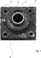
- Fig. 1 shows an example of a flange 10 with a ball bearing 12, wherein the flange 10 consists of a square iron fitting which contains a centred ball bearing 12 with a centre hole 14.
- the flange 10 must be bolted into the floor and for this purpose is provided with mounting holes 16.
- the flange 10 may optionally be countersunk in the floor.
- Fig. 2 shows an example of a right-side platform 20 and a corresponding left-side platform 30 shown at an angle from above and from one end.
- the right-side platform 20 is provided with degree marking device 24 (not shown in Fig. 2 ) and holes 21, 22 for longitudinal and width adjustment of the turning device.
- the right-side platform 20 further has a supporting element 28 (not shown in Fig. 2 ), and in the example shown, the right-side platform 20 further consists of an aluminium platform with a length of 3 metres and a width of 30 cm.
- Fig. 2 shows an example of a left-side platform 30, which is also provided with a degree marking device 34 (not shown in Fig. 2 ) and holes 31, 32 for longitudinal and width adjustment of the turning device.
- the left-side platform 30 also has a supporting element 28 (not shown in Fig. 2 ), and in the example shown, the left-side platform 30 further consists of an aluminium platform with a length of 3 metres and a width of 30 cm. Both platforms 20, 30 can, as shown in Fig. 2 , have an end part 26 on the platforms.
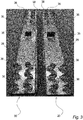
- Fig. 3 shows the undersides of the right-side and the left-side platforms 20, 30, wherein the two platforms are placed side by side with the outer sides facing each other.
- a shielding 38 is mounted, which covers the supporting element 28.
- the supporting element 28 comprises 14 castor wheels 36, which are configured to be turnable and thus movable in any direction. These wheels may e.g. each carry 500 kg. These wheels are riveted to the underside of the platform in this example and disposed in a distributed manner, such as shown in Fig. 3 , along the width and length of the platform, whereby the platform is supported by the wheels evenly distributed along the longitudinal and width directions.
- a rubber block 35 is also mounted on the underside around the middle to stabilise the platform during driving over it. Furthermore, as also explained in connection with Fig. 2 , e.g. eight holes 21, 22 have been drilled in the platform, so that the connecting device 40 (not shown in Fig. 3 ) can easily be placed with its attached guide pins 41, as will be explained later.
- Fig. 3 shows that on the outer side of the left-side platform 30, a shielding 38 is mounted, which covers the supporting element 28.
- the supporting element 28 consists for instance also here of 14 castor wheels 36, configured to be turnable and thus movable in any direction. These wheels may e.g. each carry 500 kg. These wheels are, as mentioned in connection with this example, riveted to the underside of the platform and disposed in a distributed manner, such as shown in Fig. 3 , whereby the platform is supported by the wheels evenly distributed along the longitudinal and width directions.
- a rubber block 35 is also mounted on the underside around the middle to stabilise the platform during driving over it.
- the left-side platform e.g. eight holes have been drilled in the platform, so that the connecting device 40 (not shown in Fig. 3 ) can easily be placed with its attached guide pins 41.
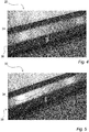
- Fig. 4 shows an example of a degree marking device 24 on a right-side platform 20
- Fig. 5 shows an example of a degree marking device 34 on a left-side platform 30, wherein the degree marking device 24, respectively 34, may be a permanently mounted indicator or arrow.
- Fig. 6 shows a connecting device 40 according to an embodiment of the invention, the underside here being shown viewed at an angle from above.
- the connecting device 40 is designed with a centre axle 42 and guide pins 41.
- the connecting device 40 is designed with two cross members 46 connected to two end plates 44 as shown, and wherein a centre part 48 is disposed between the two cross members 46, which may e.g. be X-shaped as shown, and which carries the centre axle 42.
- the two end plates 44 in this example are each provided with two guide pins 41, one in each corner, as shown.
- Figs. 7 and 8 show detail parts of Fig. 6, Fig. 7 showing the centre axle 42 mounted on the centre part 48, and Fig. 8 showing that a guide pin 41 is mounted at a corner of an end plate 44.
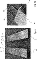
- Fig. 9 shows a right-side extension platform 50 and a left-side extension platform 60, viewed at an angle from above and from one end. Both of these extension platforms are provided with extension guide pins 52 and a snap locking device 54 as well as supporting element 28 (not shown in Fig. 9 ). Each of these extension platforms 50 and 60 may consist of an aluminium ramp/platform with e.g. a length of 1.7 metres and a width of 30 cm. On the outer side of each of these extension platforms, a shielding 38 is mounted (not shown in Fig. 9 ), and also on the right-side platform 20 and the left-side platform 39, which shielding covers the supporting element 28.
- Fig. 10 shows a detail part of Fig. 9 , wherein is shown the end of the left-side extension platform 60, on which is mounted two extension guide pins 52, each of e.g. 20 cm, used for coupling to the left-side platform 30.
- the same will apply to the right-side extension platform 50, which, via corresponding extension guide pins 52, can be coupled to the right-side platform 20.
- a locking arrangement is mounted on the left-side extension platform 60, e.g. in the form of a snap locking device 54, which is used for locking to the left-side platform 30.
- the same will apply to the right-side extension platform 50, which, via a corresponding locking arrangement in the form of e.g. a snap locking device 54, can be locked to the right-side platform 20.
- Fig. 11 shows the undersides of the right-side extension platform 50 and the left-side extension platform 60, where it is also shown that each of these is provided on the outer side with a shielding 38, which covers the supporting element 28.
- the supporting element 28 may e.g. consist of ten castor wheels 36, configured to be turnable and thus movable in any direction. These wheels may e.g. each carry 500 kg. These wheels are riveted to the underside of the respective extension platforms 50, 60 and are disposed in a distributed manner, such as shown in Fig. 11 , along the width and length of the platform, whereby the two extension platforms are supported by the wheels evenly distributed along the longitudinal and width directions.
- Fig. 12 shows an example of a right-side drive ramp 70 and a left-side drive ramp 80, viewed partially from the side and at an angle from above. Both of these are designed as drive ramps with a rest support device 72 at one end, e.g. a carrier element as shown, which on the one hand raises one end of the drive ramp, but which also has an edge that is pushed under the platform, whether it is an ordinary platform 20 or 30 or an extension platform 50 or 60, so that it will be stable when driving a vehicle up the ramp and further along the platform(s).
- a rest support device 72 at one end, e.g. a carrier element as shown, which on the one hand raises one end of the drive ramp, but which also has an edge that is pushed under the platform, whether it is an ordinary platform 20 or 30 or an extension platform 50 or 60, so that it will be stable when driving a vehicle up the ramp and further along the platform(s).
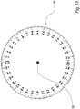
- Fig. 13 shows an example of a protractor 90 for use in setting/display of degree interval on the floor.
- This protractor 90 may e.g. be a paper template, for instance in A1 size, which is placed on the floor under the flange 10 during fixing thereof.
- a string may then e.g. be drawn from the centre of the ball bearing 12 (centre 92 of the protractor 90) through the desired degrees where photos are to be taken, and a marking can be set on the floor.
- The(se) marking(s) set on the floor can subsequently be used, e.g. with the degree marking devices 24 or 34 on the right-side platform 20, respectively the left-side platform 30, to rotate the turning device to the desired position(s) where photos are to be taken.
- 12 markings can be set at 30° intervals, corresponding to 12 photos, 24 markings at 15° intervals, corresponding to 24 photos, 36 markings at 10° intervals, corresponding to 36 photos, or 48 markings at 7.5° intervals, corresponding to 48 photos.
- Figs. 14-22 illustrate the assembly and use of an exemplary turning device according to an embodiment of the invention, as will be described in the following.
- Fig. 14 shows a right-side platform 20 placed on the floor at an appropriate distance to the flange 10 with the ball bearing, which is fixed in or to the floor.
- Fig. 15 illustrates that a connecting device 40 is located so that its centre axle (42; Figs. 6 and 7 ) is placed in the flange 10 with the ball bearing and so that its guide pins (41; Figs. 6 and 8 ) on one end plate 44 are introduced into appropriate holes of the holes 21, 22 in the right-side platform 20.
- Fig. 2 there may be e.g. two rows of holes along the platform along its length, and as shown in Fig.
- holes may be chosen so that the connecting device 40 is located around the middle and at a distance between platform and flange 10 corresponding to a relatively small track width of a vehicle or trailer.
- sub-elements with supporting element 28 may be immediately movable on the floor, due e.g. to the castor wheel design that can be moved in any direction, and due to the fact that the right-side 20 and the left-side platform 30 as well as the respective extension platforms 50, 60 are supported on the floor via the respective supporting elements and constitute independent units that can easily be handled in connection with assembly and disassembly.
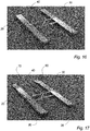
- Fig. 16 shows that a left-side platform 30 is located at the other end of the connecting device 40, and the left-side platform 30 is, in the same way as the right-side platform 20, coupled to the connecting device 40.
- a right-side 70 and a left-side drive ramp 80 can then be placed at the respective ends of the right-side platform 20 and the left-side platform 30, i.e. the ends opposite the end parts 26.
- a vehicle or a trailer (not shown) can then be driven up on the turning device, and the two drive ramps can be removed.
- the turning device with the coupled parts as well as vehicle or trailer can now be rotated around the flange 10, manually or driven by machine/electrically.
- the length of the right-side platform 20 and the left-side platform 30 may be 3 metres (and the width 30 cm), and the connecting device 40 can be sized so that the width of the turning device is 1.80 metres, so that the turning device is appropriate for ordinary vehicles and trailers.
- the turning device can be reset for large vehicles and/or trailers, such as shown in Figs. 18-22 (or can be assembled from the start for this purpose).
- the connection point between the connecting device 40 and the right-side platform 20 is moved by e.g. one end of the connecting device 40 being lifted up, the right-side platform 20 being moved forward and the guide pins of the connection point being inserted into other appropriate holes 21, 22 on the right-side platform 20.
- corresponding action may be taken in relation to the left-side platform 30. Then, as shown in Figs.
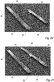
- a right-side extension platform 50 and a left-side extension platform 60 can be connected, which in both cases takes place by introducing the extension guide pins 52 on the extension platforms into the respective 'main platforms' 20 and 30, after which the parts are locked together with e.g. the snap locking devices 54.
- the handling of the extension platforms 50 and 60 is simple, since they are both 'run' to the ends of the respective 'main platforms' 20 and 30, the supporting elements 28, e.g. comprising castor wheels 36, ensuring easy handling, and since extension platforms and 'main platforms' are further located at the same height, making them easy to couple together.
- a right-side 70 and a left-side drive ramp 80 may then be placed at the respective ends of the right-side extension platform 50 and the left-side extension platform 60, opposite the end parts 26.
- a vehicle or a trailer (not shown) can then be driven up on the turning device, and the two drive ramps can be removed.
- the turning device with the coupled parts as well as vehicle or trailer can now be rotated around the flange 10, manually or driven by machine/electrically.
- the length of the right-side platform 20 and the left-side platform 30 may be 3 metres (and the width 30 cm), and the length of the extension platforms may be 1.70 metres (also with the width 30 cm) so that an overall platform length of 4.70 metres is achieved.
- the connecting device 40 may be sized so that the width of the turning device can be up to 2.00 metres, so that in total, the turning device in this configuration is appropriate for large vehicles and trailers.
- the operation can be manual, i.e. the turning device is turned manually and stopped at the desired degree markings, the degree marking device 24 or 34 in the form of indicator, arrow, laser light or the like being aligned with respective markings on the floor.
- the operation may also be by machine and more or less automated, as the turning device may be turned or driven by an electric motor, e.g. by means of a remote control and/or a pedal function.
- Said electric motor may be linked directly to a turning wheel that drives the turning device round, or the electric motor may be connected via gears, drive belt or drive shaft as force-transmitting element(s) to e.g. a wheel that may drive the turning device round.
- this may be a drive unit which includes the electric motor and which can be placed/mounted on one of the platforms. Since such machine operation may take place e.g. through remote control, there is also a possibility of a greater or lesser degree of automation, as the electric motor may e.g. be controlled in such a way that it turns the turning device by a certain angle, after which it stops at a photo position, following which another angular interval is turned, etc.
- the electric motor may e.g. be controlled in such a way that it turns the turning device by a certain angle, after which it stops at a photo position, following which another angular interval is turned, etc.
- Other designs of the drive system, its operation and control are possible.
- a right-side platform 20 a left-side platform 30, a right-side extension platform 50 and a left-side extension platform 60 are used, wherein the two sides of the turning device are connected by a connecting device 40.
- the platforms are generally designed as aluminium platforms, just as the connecting device 40 may be designed in aluminium.
- the platforms 20, 30, 50 and 60 are each embodied with a supporting element 28 on their underside (not shown in Fig. 23 ), e.g. comprising a number of castor wheels configured to be turnable and thus moveable in any direction.
- These wheels may e.g. each carry 500 kg.
- the wheels are e.g. riveted to the underside of the respective platforms and are disposed in a distributed manner (e.g. as shown in the previous figures) along the width and length of the platforms, whereby the platforms are supported by the wheels evenly distributed along the longitudinal and width directions.
- the weight of a vehicle will thus also be evenly distributed on the platforms.
- the respective platforms 20, 30, 50 and 60 can thus also be moved individually when they are not coupled together, which facilitates handling.
- platforms 20, 30, 50 and 60 may be designed with end parts, shielding on one side etc., and otherwise as described above.
- the right-side platform 20, the left-side platform 30, the right-side extension platform 50 and the left-side extension platform 60 in this design are also provided with holes 23, 33 in the longitudinal direction, wherein these holes 23, 33 are designed as horizontal holes, e.g. as shown in that guide bushings 82 are provided along the sides of the respective platforms.
- Said guide bushings 82 which may be tubular elements, e.g. round shape or square, may optionally extend over a substantial part of the width of each platform and under the same. As shown, a piece may protrude toward the middle of the turning device, which may facilitate assembly etc., since a locking grip 84 may be provided at this point, as illustrated.
- These locking grips 84 which may be screw grips and are manually operated, are used to retain e.g. the connecting device 40, so that, after adjustment, a desired width of the turning device is achieved.
- a separate cross member 49 may be placed, which is led through two of the guide bushings and retained by the locking grips 84, so that the turning device achieves greater rigidity and stability.
- separate cross members 49 may be mounted also to the other guide bushings 82 to connect the left and right sides of the platforms 20, 30 and the extension platforms 50, 60.
- the turning device may be provided with a drive unit 100, which may be mounted on the left platform 30 (as shown) or on the right platform 20, preferably in the area between the two platforms.
- a drive unit with which the turning device can be rotated in one or both directions around the flange 10, will be mentioned later.
- the drive unit 100 may, as outlined, be designed with one or more guide bushings 82 horizontally oriented, so that the drive unit may be coupled to e.g. the left-side platform 30 using a separate cross member which is led to one of the guide bushings 82 of the platform.
- a separate cross member 49 for retaining the drive unit 100 may extend from one platform to the other, such as shown at the top of Fig. 23 .
- the separate cross member 49 may extend under the platforms 20 and 30 through a substantial part of their width.
- the separate cross member 49 may also extend on the other side of the platforms, which may also be the case with other locations of a separate cross member 49.
- the connecting device 40 is located centrally for the turning device and in such a way that it is coupled to the guide bushings 82 on all four platforms 20, 30, 50 and 60.
- the connecting device 40 thus serves not only to maintain a distance between the right and left side, but also to attach the right-side platform 20 to the right-side extension platform 50, as well as to attach the left-side platform 30 to the left-side extension platform 60.
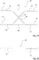
- Fig. 24 shows, viewed from above, an embodiment of the connecting device 40 for use at the turning device as shown in Fig. 23 .
- This connecting device 40 is substantially designed as described in connection with Fig. 6 , i.e. with a centre part 48, e.g. X-shaped, which carries in the middle the indicated centre axle 42, and which connects the two cross members 46.
- a guide pin 41 is disposed, which as described is designed to be introduced into a horizontal hole 23, 33 on the guide bushing 82 of a platform.
- the guide pins 41 may be locked in the guide bushings by means of the locking grips 84, which may be designed as screw clamps or the like.
- the guide pins 41 may be designed with recesses, through-bores or the like, constituting locking holes 47. These may, as illustrated in Fig. 24 be placed with predetermined intervals, at predetermined positions or the like, so that the width of the turning device can be adjusted in appropriate steps. It should be understood, however, that a stepless adjustment may also be used, e.g. if the locking grips 84 can squeeze against the guide pins 41.
- Fig. 25 shows a separate cross member 49 such as used at the turning device shown in Fig. 23 .
- this separate cross member 49 corresponds to the cross member 46 of the connecting device with extensions in the form of guide pins, and locking holes 47 are thus also provided on the separate cross member 49, located at predetermined intervals, at predetermined positions or the like, so that the separate cross member can be coupled and locked to the respective guide bushings 82 in steps (or possibly steplessly), corresponding to the set width.
- the separate cross members 49 and the guide pins 41 are designed so that they correspond in form to the holes 23, 33 in the guide bushings 82, e.g. square or circular in cross-section.
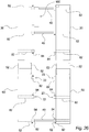
- Fig. 26 shows a turning device substantially similar to that shown in Fig. 23 , but wherein it is shown that the right-side extension platform 50 and the left-side extension platform 60 are separated from the two platforms 20 and 30, and wherein, for the sake of clarity, the connecting device 40 as well as one of the cross members 49 are removed (which takes place by pushing the two sides of the platforms from each other after all the locking grips 84 have been loosened).
- the extension platforms 50 and 60 are provided with extension guide pins 52 (as also described in connection with Figs. 9 and 10 ) to establish connection with the respective 'main platforms' 20 and 30.
- a lock may thus also be designed which keeps extension platform and 'main platform' together, e.g. using the guide bushings 82 with locking grip 84, which at each end of each platform 20, 30 may grip onto the extension guide pins 52, or a snap locking device 54 may be used (see Fig. 10 ).
- Fig. 26 further shows that the guide bushings 82, which may be designed from square tubes, round tubes or the like, may be placed under the respective platforms and in such a way that they are extended under the platforms substantially along the width of the platforms. It should be noted that e.g. separate cross members 49, optionally in shorter form, may be mounted in the guide bushings 82 and protrude on the outer side of the platforms, e.g. in support of additional elements, cover plates and the like. It is furthermore shown that, for the same purpose at the ends of the platforms (as shown at the bottom of Fig. 26 ), guide bushings 82 may run in the longitudinal direction.
- drive ramps 70 and 80 may be used, as explained in connection with Figs. 12 , 17 and 22 , and the turning device may be used in substantially the same manner.
- the platforms used may be designed in different appropriate sizes, but as an example it may be mentioned that 'main' platforms as well as extension platforms may have a length of 2-3 m each, e.g. 2.35 m, and that the widths may be in the range of 0.3 m to 0.8 m, 0.5 m to 0.8 m or in the range of 0.6 m to 0.7 m. It is clear that other dimensions are possible.
- Fig. 27 outlines an embodiment of a drive unit 100, wherein the actual unit has a guide bushing 82 at each end, with which the unit, via two separate cross members 49 or in a different manner, may be mounted on the side of a platform.
- the drive unit 10 has a drive wheel, drive roller or the like 102, which can move the end of the turning device in one or both directions, so that the turning device is turned around the fixed centre of rotation on the floor. This movement may take place using an electric motor 104, which is supplied with energy from a voltage supply 106, e.g. a battery, via a control unit 108, which e.g. controls the direction of turning, travel or angular turning of the turning device etc., as will be well known to a person skilled in the art.
- a voltage supply 106 e.g. a battery
- control unit 108 which e.g. controls the direction of turning, travel or angular turning of the turning device etc.
- the drive unit 100 may be provided with a distance and/or degree measuring device 114, which, e.g. by measuring revolutions on the electric motor, may calculate distance and/or angular turning of the turning device.
- the unit may further comprise a receiver/transmitter 112, so that the drive unit 100 may be controlled using a remote control 110.
- the drive unit may thus be configured, when activated via the remote control, to turn a set angle, after which it stops on it own etc. Other ways of automating the operation may be exercised.
- this invention can easily be set in degrees so that the user can easily set the device to turn exactly the desired number of degrees (as opposed to other devices where degree settings exist only on stationary power-driven platforms) - that it can easily and without the use of tools and measuring equipment be set so that it can be used for vehicles and trailers of up to 5 tonnes of empty weight with different wheel bases and track widths (as opposed to other devices which can only be either adjusted on wheel base or track width).
- the castor wheels used make it possible to adjust the wheel base and track width smoothly (as opposed to devices with attached rollers and fixed wheels).
- the advantages of this invention is that it is easy to assemble/disassemble so that a single person can do this alone. It is easily adjustable relative to wheel base and track width, it is mobile and may thus easily be packed away so that it does not take up unnecessary space (as opposed to the known stationary versions). It is made of aluminium, which makes it light and easily manageable.
Landscapes
- Engineering & Computer Science (AREA)
- Mechanical Engineering (AREA)
- Physics & Mathematics (AREA)
- General Physics & Mathematics (AREA)
- General Engineering & Computer Science (AREA)
- Life Sciences & Earth Sciences (AREA)
- Geology (AREA)
- Structural Engineering (AREA)
- Handcart (AREA)
- A Measuring Device Byusing Mechanical Method (AREA)
- Automatic Assembly (AREA)
Abstract
Description
- The invention relates to a turning device for horizontal rotation of vehicles and trailers. The invention thus relates to a turning device as specified in the preamble of claim 1.
- 360-degree turning devices of this kind are known for use in degree-separated photography of vehicles/trailers. These known devices are generally relatively large and heavy stationary installations, which for most car and trailer dealers would be a very expensive solution, and for some even a financially impossible solution. At the same time, the known solutions are extremely time-consuming to assemble and disassemble again.
- An example of prior art is indicated in
FR 2,699,876 A1 - It is an object of the invention to provide a turning device which is easy to assemble and/or disassemble, so that a single person can do this alone. Furthermore, it is an object to provide such a turning device which is easily adjustable in relation to wheel base and track width, which is mobile and can thus easily be packed away so that it does not take up unnecessary space (as opposed to the known stationary versions).
- This and other objects are achieved by the invention, as will be explained in further detail in the following.
- The invention relates, as set forth in claim 1, to a turning device for horizontal 360-degree rotation of vehicles and trailers, wherein the turning device comprises
- a right-side platform and a left-side platform, each with a supporting element,
- a connecting device,
- a centre device for attachment to a floor, and
- a right-side drive ramp and a left-side drive ramp,
- The invention is characterised in that
- the connecting device has a centre axle that can be placed in said centre device, that
- the connecting device has guide pins for establishing connection to the right-side platform and the left-side platform via respective holes of said plurality of holes, that
- the turning device comprises a device for indicating the turning position of the turning device, that
- the turning device comprises a right-side extension platform and a left-side extension platform, designed to extend the right-side platform and the left-side platform, respectively, wherein each of the right-side extension platform and the left-side extension platform has extension guide pins at an end for cooperation with the right-side platform and the left-side platform, respectively, and that
- each of the right-side extension platform and the left-side extension platform has a supporting element.
- By the invention the advantages are achieved that the turning device is easy to assemble and/or disassemble, so that a single person can do this alone. It is easily adjustable in relation to wheel base and track width, and furthermore, it is mobile and can thus easily be packed away so that it does not take up unnecessary space, as opposed to the known stationary versions.
- By the invention it is achieved that a vehicle or trailer can be photographed while it rotates on the turning device according to the invention and in a self-determined degree interval (e.g. 15 degrees = 24 photos). These photos are subsequently used in a photo editing programme, which is able to create a 360° digital display for potential customers, who thus have the opportunity of turning and zooming in and out themselves on the vehicle/trailer, thereby achieving a more LIVE display. The turning device and/or use according to the invention will thus also be referred to as 'EasyCarDisplay' .
- Further it is achieved by this invention that it can be easily set to degrees, so that the user can easily set the turning device to turn exactly the desired number of degrees (as opposed to other devices where degree settings only exist on stationary power-driven platforms), and that it can be set easily and without the use of tools and measuring equipment, so that it can be used for vehicles and trailers up to e.g. 5 tonnes of empty weight with different wheel bases and track widths (as opposed to other devices which can only be adjusted on either wheel base or track width).
- It should be noted that the term 'platform' in relation to the invention is generally understood as driving elements for vehicles, such as ramps, platforms etc., designed as normally elongate elements, onto which a vehicle can drive or be placed, such platforms being arranged in pairs, parallel to each other, corresponding to the vehicle track width. It should also be understood that such platforms can be placed horizontally or sloping, in the latter case e.g. when they are used as drive ramps. In the following, the designation platform will be used in the above-mentioned sense.
- According to an expedient embodiment, such as set forth in claim 2, said supporting element for the right-side platform, the left-side platform, the right-side extension platform and the left-side extension platform may comprise units selected from the group comprising:
- castor wheels,
- steel rollers,
- ball bearings,
- roller bearings, and
- swivel wheels with motor.
- Hereby, it is achieved, e.g. by using castor wheels that can be moved in any direction, that it becomes possible to adjust the wheel base and track width smoothly (as opposed to devices with attached rollers and fixed wheels), the respective platforms being easily movably on the floor in any direction during the adjustment.
- According to an expedient embodiment, such as set forth in
claim 3, the centre device for attachment to a floor may comprise a flange with ball bearing, wherein the centre axle on the connecting device can be placed in the ball bearing. Hereby, it is achieved that the turning device can be easily placed and assembled around the centre device, and that the centre device, when the turning device is removed, will not be in the way of any other exploitation of the floor. However, it is clear that the centre device may instead be constituted by a pin or the like attached to the floor. Likewise, another type of bearing than a ball bearing may be used. - According to another expedient embodiment, such as set forth in claim 4, said supporting element for the right-side platform, the left-side platform, the right-side extension platform and the left-side extension platform may comprise a number of units disposed under the respective platforms, distributed along the longitudinal and width direction of the respective platforms.
- According to a further expedient embodiment, such as set forth in
claim 5, said supporting element for each platform may comprise a plurality of units, e.g. 10 or more wheels, castor wheels or similar wheels. This ensures that the individual platforms are supported over a larger surface, and, when they are not assembled, can be moved across the floor as independent units. Furthermore, an advantageous distribution of the weight of a vehicle is achieved when the platforms are assembled and a vehicle is driven onto and placed on the turning device. The number of castor wheels per platform may be e.g. 10-30, 10-20 or even more. - According to yet another expedient embodiment, such as set forth in claim 6, the device for indicating the turning position of the turning device may comprise a degree marking device in the form of a fixedly mounted indicator or arrow on the right-side platform and/or the left-side platform, whereby the turning position can be read, e.g. via degree markings on a floor.
- According to a further expedient embodiment, such as set forth in claim 7, the device for indicating the turning position of the turning device may comprise laser light pointing downwards on degree markings on a floor.
- According to yet another expedient embodiment, such as set forth in claim 8, the device for indicating the turning position of the turning device may comprise a distance and/or degree measuring device located on the turning device to provide a measure of distance and/or angle rotation during rotation of the turning device. This may e.g. be utilised for a more or less automated use, so that the turning device automatically stops when it has turned to a set angle.
- According to a further expedient embodiment, such as set forth in
claim 9, the turning device may be embodied using aluminium for the design of platforms, drive ramps, the connecting device and/or other elements, which makes the turning device and its sub-elements light and easy to handle. - According to yet another expedient embodiment, such as set forth in
claim 10, the turning device may be adapted for machine operation and handling, driven by an electric motor, e.g. by means of a remote control and/or a pedal function, and wherein said electric motor is in communication with a turning wheel, e.g. via a connection with gears, drive belt or drive shaft for turning the turning device. - Thereby, the turning device, in addition to being manually operated, may be arranged to be driven by an electric motor. Said electric motor may be linked directly to a turning wheel that drives the turning device around, or the electric motor may be connected via gears, drive belt or drive shaft as force-transmitting element(s) to e.g. a wheel that may drive the turning device round. For example, this may be a drive unit which includes the electric motor, and which may be mounted on one of the platforms. Since such mechanical operation according to the embodiment may take place via remote control, i.e. comprising a control of the electric motor, there is a possibility of a greater or lesser degree of automation of the use of the turning device.
- According to yet another expedient embodiment, such as set forth in claim 11, the right-side extension platform and the left-side extension platform may each have a locking device, such as a snap locking device, for locking to the right-side platform and the left-side platform, respectively.
- The invention will be explained in more detail in the following with reference to the drawings, where
- Fig. 1
- shows a flange with ball bearing for bolting to the floor,
- Fig. 2
- shows a right-side and a left-side platform, viewed at an angle from above,
- Fig. 3
- shows the corresponding undersides of the right-side and the left-side platforms,
- Fig. 4
- shows an example of a degree marking device on a right-side platform,
- Fig. 5
- shows, corresponding to
Fig. 4 , an example of a degree marking device on a left-side platform, - Fig. 6
- shows a connecting device according to an embodiment of the invention,
- Fig. 7
- is a detail part of
Fig. 6 , in which the centre axle is shown, - Fig. 8
- is a detail part of
Fig. 6 in which a guide pin is shown, - Fig. 9
- shows a right-side and a left-side extension platform, viewed at an angle from above,
- Fig. 10
- is a detail part of
Fig. 9 , in which guide pins and locking arrangement are shown, - Fig. 11
- shows, corresponding to
Fig. 9 , the undersides of the right-side and the left-side extension platforms, - Fig. 12
- shows an example of a right-side and left-side drive ramp, viewed partially from the side and at an angle from above,
- Fig. 13
- shows an example of a protractor for use when setting and/or displaying a degree interval on a floor,
- Figs. 14-22
- illustrate the assembly of an exemplary turning device according to an embodiment of the invention,
- Fig. 23
- illustrates a turning device according to a further embodiment of the invention, viewed from above,
- Fig. 24
- shows, viewed from above, an embodiment of the connecting device for use at the turning device,
- Fig. 25
- shows a separate cross member for use in connection with the embodiment shown in
Fig. 23 , - Fig. 26
- shows a turning device substantially corresponding to the embodiment shown in
Fig. 23 , and - Fig. 27
- shows an embodiment of a drive unit.
- Various embodiments of a turning device according to the invention as well as various embodiments of sub-elements thereof will be described in the following with reference to
Figs. 1-13 and with reference toFigs. 23-27 . -
Fig. 1 shows an example of aflange 10 with aball bearing 12, wherein theflange 10 consists of a square iron fitting which contains acentred ball bearing 12 with acentre hole 14. Theflange 10 must be bolted into the floor and for this purpose is provided with mountingholes 16. Theflange 10 may optionally be countersunk in the floor. -
Fig. 2 shows an example of a right-side platform 20 and a corresponding left-side platform 30 shown at an angle from above and from one end. The right-side platform 20 is provided with degree marking device 24 (not shown inFig. 2 ) and holes 21, 22 for longitudinal and width adjustment of the turning device. The right-side platform 20 further has a supporting element 28 (not shown inFig. 2 ), and in the example shown, the right-side platform 20 further consists of an aluminium platform with a length of 3 metres and a width of 30 cm. Similarly,Fig. 2 shows an example of a left-side platform 30, which is also provided with a degree marking device 34 (not shown inFig. 2 ) and holes 31, 32 for longitudinal and width adjustment of the turning device. The left-side platform 30 also has a supporting element 28 (not shown inFig. 2 ), and in the example shown, the left-side platform 30 further consists of an aluminium platform with a length of 3 metres and a width of 30 cm. Bothplatforms Fig. 2 , have anend part 26 on the platforms. -
Fig. 3 shows the undersides of the right-side and the left-side platforms side platform 20, a shielding 38 is mounted, which covers the supportingelement 28. As shown in this example, the supportingelement 28 comprises 14castor wheels 36, which are configured to be turnable and thus movable in any direction. These wheels may e.g. each carry 500 kg. These wheels are riveted to the underside of the platform in this example and disposed in a distributed manner, such as shown inFig. 3 , along the width and length of the platform, whereby the platform is supported by the wheels evenly distributed along the longitudinal and width directions. Arubber block 35 is also mounted on the underside around the middle to stabilise the platform during driving over it. Furthermore, as also explained in connection withFig. 2 , e.g. eightholes Fig. 3 ) can easily be placed with its attached guide pins 41, as will be explained later. - Similarly,
Fig. 3 shows that on the outer side of the left-side platform 30, a shielding 38 is mounted, which covers the supportingelement 28. The supportingelement 28 consists for instance also here of 14castor wheels 36, configured to be turnable and thus movable in any direction. These wheels may e.g. each carry 500 kg. These wheels are, as mentioned in connection with this example, riveted to the underside of the platform and disposed in a distributed manner, such as shown inFig. 3 , whereby the platform is supported by the wheels evenly distributed along the longitudinal and width directions. Arubber block 35 is also mounted on the underside around the middle to stabilise the platform during driving over it. Furthermore, also by the left-side platform, e.g. eight holes have been drilled in the platform, so that the connecting device 40 (not shown inFig. 3 ) can easily be placed with its attached guide pins 41. -
Fig. 4 shows an example of adegree marking device 24 on a right-side platform 20, and similarly,Fig. 5 shows an example of adegree marking device 34 on a left-side platform 30, wherein thedegree marking device 24, respectively 34, may be a permanently mounted indicator or arrow. -
Fig. 6 shows a connectingdevice 40 according to an embodiment of the invention, the underside here being shown viewed at an angle from above. The connectingdevice 40 is designed with acentre axle 42 and guide pins 41. In the example shown, the connectingdevice 40 is designed with twocross members 46 connected to twoend plates 44 as shown, and wherein acentre part 48 is disposed between the twocross members 46, which may e.g. be X-shaped as shown, and which carries thecentre axle 42. The twoend plates 44 in this example are each provided with two guide pins 41, one in each corner, as shown. It should be understood that thecentre axle 42 and the guide pins 41, when the connectingdevice 40 is used, will protrude downwards, and that thecentre axle 42 will be insertable into thecentre hole 14 in theflange 10, and that the guide pins 41 will match to be insertable into selected holes of theholes Figs. 7 and 8 show detail parts ofFig. 6, Fig. 7 showing thecentre axle 42 mounted on thecentre part 48, andFig. 8 showing that aguide pin 41 is mounted at a corner of anend plate 44. -
Fig. 9 shows a right-side extension platform 50 and a left-side extension platform 60, viewed at an angle from above and from one end. Both of these extension platforms are provided with extension guide pins 52 and asnap locking device 54 as well as supporting element 28 (not shown inFig. 9 ). Each of theseextension platforms Fig. 9 ), and also on the right-side platform 20 and the left-side platform 39, which shielding covers the supportingelement 28. -
Fig. 10 shows a detail part ofFig. 9 , wherein is shown the end of the left-side extension platform 60, on which is mounted two extension guide pins 52, each of e.g. 20 cm, used for coupling to the left-side platform 30. The same will apply to the right-side extension platform 50, which, via corresponding extension guide pins 52, can be coupled to the right-side platform 20. Further, a locking arrangement is mounted on the left-side extension platform 60, e.g. in the form of asnap locking device 54, which is used for locking to the left-side platform 30. The same will apply to the right-side extension platform 50, which, via a corresponding locking arrangement in the form of e.g. asnap locking device 54, can be locked to the right-side platform 20. -
Fig. 11 shows the undersides of the right-side extension platform 50 and the left-side extension platform 60, where it is also shown that each of these is provided on the outer side with a shielding 38, which covers the supportingelement 28. As shown, the supportingelement 28 may e.g. consist of tencastor wheels 36, configured to be turnable and thus movable in any direction. These wheels may e.g. each carry 500 kg. These wheels are riveted to the underside of therespective extension platforms Fig. 11 , along the width and length of the platform, whereby the two extension platforms are supported by the wheels evenly distributed along the longitudinal and width directions. -
Fig. 12 shows an example of a right-side drive ramp 70 and a left-side drive ramp 80, viewed partially from the side and at an angle from above. Both of these are designed as drive ramps with arest support device 72 at one end, e.g. a carrier element as shown, which on the one hand raises one end of the drive ramp, but which also has an edge that is pushed under the platform, whether it is anordinary platform extension platform -
Fig. 13 shows an example of aprotractor 90 for use in setting/display of degree interval on the floor. Thisprotractor 90 may e.g. be a paper template, for instance in A1 size, which is placed on the floor under theflange 10 during fixing thereof. A string may then e.g. be drawn from the centre of the ball bearing 12 (centre 92 of the protractor 90) through the desired degrees where photos are to be taken, and a marking can be set on the floor. The(se) marking(s) set on the floor can subsequently be used, e.g. with thedegree marking devices side platform 20, respectively the left-side platform 30, to rotate the turning device to the desired position(s) where photos are to be taken. For example, 12 markings can be set at 30° intervals, corresponding to 12 photos, 24 markings at 15° intervals, corresponding to 24 photos, 36 markings at 10° intervals, corresponding to 36 photos, or 48 markings at 7.5° intervals, corresponding to 48 photos. -
Figs. 14-22 illustrate the assembly and use of an exemplary turning device according to an embodiment of the invention, as will be described in the following. -
Fig. 14 shows a right-side platform 20 placed on the floor at an appropriate distance to theflange 10 with the ball bearing, which is fixed in or to the floor.Fig. 15 illustrates that a connectingdevice 40 is located so that its centre axle (42;Figs. 6 and 7 ) is placed in theflange 10 with the ball bearing and so that its guide pins (41;Figs. 6 and 8 ) on oneend plate 44 are introduced into appropriate holes of theholes side platform 20. As illustrated inFig. 2 , there may be e.g. two rows of holes along the platform along its length, and as shown inFig. 15 , holes may be chosen so that the connectingdevice 40 is located around the middle and at a distance between platform andflange 10 corresponding to a relatively small track width of a vehicle or trailer. It should be noted that during work on the sub-elements of the turning device, sub-elements with supportingelement 28 may be immediately movable on the floor, due e.g. to the castor wheel design that can be moved in any direction, and due to the fact that the right-side 20 and the left-side platform 30 as well as therespective extension platforms -
Fig. 16 shows that a left-side platform 30 is located at the other end of the connectingdevice 40, and the left-side platform 30 is, in the same way as the right-side platform 20, coupled to the connectingdevice 40. As shown inFig. 17 , a right-side 70 and a left-side drive ramp 80 can then be placed at the respective ends of the right-side platform 20 and the left-side platform 30, i.e. the ends opposite theend parts 26. A vehicle or a trailer (not shown) can then be driven up on the turning device, and the two drive ramps can be removed. The turning device with the coupled parts as well as vehicle or trailer can now be rotated around theflange 10, manually or driven by machine/electrically. As previously mentioned, the length of the right-side platform 20 and the left-side platform 30 may be 3 metres (and thewidth 30 cm), and the connectingdevice 40 can be sized so that the width of the turning device is 1.80 metres, so that the turning device is appropriate for ordinary vehicles and trailers. - The turning device can be reset for large vehicles and/or trailers, such as shown in
Figs. 18-22 (or can be assembled from the start for this purpose). As shown inFig. 18 , the connection point between the connectingdevice 40 and the right-side platform 20 is moved by e.g. one end of the connectingdevice 40 being lifted up, the right-side platform 20 being moved forward and the guide pins of the connection point being inserted into otherappropriate holes side platform 20. As shown inFig. 19 , corresponding action may be taken in relation to the left-side platform 30. Then, as shown inFigs. 20 and 21 , a right-side extension platform 50 and a left-side extension platform 60 can be connected, which in both cases takes place by introducing the extension guide pins 52 on the extension platforms into the respective 'main platforms' 20 and 30, after which the parts are locked together with e.g. thesnap locking devices 54. It should be noted that the handling of theextension platforms elements 28, e.g. comprisingcastor wheels 36, ensuring easy handling, and since extension platforms and 'main platforms' are further located at the same height, making them easy to couple together. - As shown in
Fig. 22 , a right-side 70 and a left-side drive ramp 80 may then be placed at the respective ends of the right-side extension platform 50 and the left-side extension platform 60, opposite theend parts 26. A vehicle or a trailer (not shown) can then be driven up on the turning device, and the two drive ramps can be removed. The turning device with the coupled parts as well as vehicle or trailer can now be rotated around theflange 10, manually or driven by machine/electrically. As previously mentioned, the length of the right-side platform 20 and the left-side platform 30 may be 3 metres (and thewidth 30 cm), and the length of the extension platforms may be 1.70 metres (also with thewidth 30 cm) so that an overall platform length of 4.70 metres is achieved. The connectingdevice 40 may be sized so that the width of the turning device can be up to 2.00 metres, so that in total, the turning device in this configuration is appropriate for large vehicles and trailers. - In connection with the use of the turning device as explained above, the operation can be manual, i.e. the turning device is turned manually and stopped at the desired degree markings, the
degree marking device - With reference to
Figs. 23-27 , further embodiments of the invention will be described, wherein generally the same elements as previously described will be referred to using the same reference numerals. - As shown in
Fig. 23 , which illustrates a turning device according to an embodiment of the invention, viewed from above, as previously mentioned, a right-side platform 20, a left-side platform 30, a right-side extension platform 50 and a left-side extension platform 60 are used, wherein the two sides of the turning device are connected by a connectingdevice 40. The platforms are generally designed as aluminium platforms, just as the connectingdevice 40 may be designed in aluminium. As with the respective platforms described above and shown inFigs. 1-22 , theplatforms element 28 on their underside (not shown inFig. 23 ), e.g. comprising a number of castor wheels configured to be turnable and thus moveable in any direction. These wheels may e.g. each carry 500 kg. The wheels are e.g. riveted to the underside of the respective platforms and are disposed in a distributed manner (e.g. as shown in the previous figures) along the width and length of the platforms, whereby the platforms are supported by the wheels evenly distributed along the longitudinal and width directions. The weight of a vehicle will thus also be evenly distributed on the platforms. Therespective platforms - Furthermore, the
platforms - For use in coupling with the connecting
device 40, the right-side platform 20, the left-side platform 30, the right-side extension platform 50 and the left-side extension platform 60 in this design are also provided withholes holes guide bushings 82 are provided along the sides of the respective platforms. - Said
guide bushings 82, which may be tubular elements, e.g. round shape or square, may optionally extend over a substantial part of the width of each platform and under the same. As shown, a piece may protrude toward the middle of the turning device, which may facilitate assembly etc., since a lockinggrip 84 may be provided at this point, as illustrated. These locking grips 84, which may be screw grips and are manually operated, are used to retain e.g. the connectingdevice 40, so that, after adjustment, a desired width of the turning device is achieved. - As further shown in
Fig. 23 , e.g. at the end of the twoextension platforms separate cross member 49 may be placed, which is led through two of the guide bushings and retained by the locking grips 84, so that the turning device achieves greater rigidity and stability. Likewise, as shown,separate cross members 49 may be mounted also to theother guide bushings 82 to connect the left and right sides of theplatforms extension platforms - It is further shown that the turning device may be provided with a
drive unit 100, which may be mounted on the left platform 30 (as shown) or on theright platform 20, preferably in the area between the two platforms. An example of such a drive unit with which the turning device can be rotated in one or both directions around theflange 10, will be mentioned later. Thedrive unit 100 may, as outlined, be designed with one ormore guide bushings 82 horizontally oriented, so that the drive unit may be coupled to e.g. the left-side platform 30 using a separate cross member which is led to one of theguide bushings 82 of the platform. Optionally, such aseparate cross member 49 for retaining thedrive unit 100 may extend from one platform to the other, such as shown at the top ofFig. 23 . It is also indicated by broken lines here that theseparate cross member 49 may extend under theplatforms separate cross member 49 may also extend on the other side of the platforms, which may also be the case with other locations of aseparate cross member 49. - As is also shown in
Fig. 23 , the connectingdevice 40 is located centrally for the turning device and in such a way that it is coupled to theguide bushings 82 on all fourplatforms device 40 thus serves not only to maintain a distance between the right and left side, but also to attach the right-side platform 20 to the right-side extension platform 50, as well as to attach the left-side platform 30 to the left-side extension platform 60. However, it should be understood that there may be additional locking means to hold the extension platforms onto the 'main' platforms. -
Fig. 24 shows, viewed from above, an embodiment of the connectingdevice 40 for use at the turning device as shown inFig. 23 . This connectingdevice 40 is substantially designed as described in connection withFig. 6 , i.e. with acentre part 48, e.g. X-shaped, which carries in the middle theindicated centre axle 42, and which connects the twocross members 46. In this embodiment, in continuation of each cross member 46 aguide pin 41 is disposed, which as described is designed to be introduced into ahorizontal hole guide bushing 82 of a platform. As mentioned, the distance between the platforms may thus be adjusted, and as mentioned, the guide pins 41 may be locked in the guide bushings by means of the locking grips 84, which may be designed as screw clamps or the like. For the purposes of this locking, the guide pins 41 may be designed with recesses, through-bores or the like, constituting locking holes 47. These may, as illustrated inFig. 24 be placed with predetermined intervals, at predetermined positions or the like, so that the width of the turning device can be adjusted in appropriate steps. It should be understood, however, that a stepless adjustment may also be used, e.g. if the locking grips 84 can squeeze against the guide pins 41. -
Fig. 25 shows aseparate cross member 49 such as used at the turning device shown inFig. 23 . As can be seen, thisseparate cross member 49 corresponds to thecross member 46 of the connecting device with extensions in the form of guide pins, and lockingholes 47 are thus also provided on theseparate cross member 49, located at predetermined intervals, at predetermined positions or the like, so that the separate cross member can be coupled and locked to therespective guide bushings 82 in steps (or possibly steplessly), corresponding to the set width. - The
separate cross members 49 and the guide pins 41 are designed so that they correspond in form to theholes guide bushings 82, e.g. square or circular in cross-section. -
Fig. 26 shows a turning device substantially similar to that shown inFig. 23 , but wherein it is shown that the right-side extension platform 50 and the left-side extension platform 60 are separated from the twoplatforms device 40 as well as one of thecross members 49 are removed (which takes place by pushing the two sides of the platforms from each other after all the locking grips 84 have been loosened). As can be seen, theextension platforms Figs. 9 and 10 ) to establish connection with the respective 'main platforms' 20 and 30. A lock may thus also be designed which keeps extension platform and 'main platform' together, e.g. using theguide bushings 82 with lockinggrip 84, which at each end of eachplatform snap locking device 54 may be used (seeFig. 10 ). -
Fig. 26 further shows that theguide bushings 82, which may be designed from square tubes, round tubes or the like, may be placed under the respective platforms and in such a way that they are extended under the platforms substantially along the width of the platforms. It should be noted that e.g.separate cross members 49, optionally in shorter form, may be mounted in theguide bushings 82 and protrude on the outer side of the platforms, e.g. in support of additional elements, cover plates and the like. It is furthermore shown that, for the same purpose at the ends of the platforms (as shown at the bottom ofFig. 26 ),guide bushings 82 may run in the longitudinal direction. - It should be noted that, also in connection with the turning device as shown in
Figs. 23 and26 , drive ramps 70 and 80 may be used, as explained in connection withFigs. 12 ,17 and22 , and the turning device may be used in substantially the same manner. - The platforms used may be designed in different appropriate sizes, but as an example it may be mentioned that 'main' platforms as well as extension platforms may have a length of 2-3 m each, e.g. 2.35 m, and that the widths may be in the range of 0.3 m to 0.8 m, 0.5 m to 0.8 m or in the range of 0.6 m to 0.7 m. It is clear that other dimensions are possible.
-
Fig. 27 outlines an embodiment of adrive unit 100, wherein the actual unit has aguide bushing 82 at each end, with which the unit, via twoseparate cross members 49 or in a different manner, may be mounted on the side of a platform. Thedrive unit 10 has a drive wheel, drive roller or the like 102, which can move the end of the turning device in one or both directions, so that the turning device is turned around the fixed centre of rotation on the floor. This movement may take place using anelectric motor 104, which is supplied with energy from avoltage supply 106, e.g. a battery, via acontrol unit 108, which e.g. controls the direction of turning, travel or angular turning of the turning device etc., as will be well known to a person skilled in the art. In this connection, thedrive unit 100 may be provided with a distance and/ordegree measuring device 114, which, e.g. by measuring revolutions on the electric motor, may calculate distance and/or angular turning of the turning device. The unit may further comprise a receiver/transmitter 112, so that thedrive unit 100 may be controlled using aremote control 110. The drive unit may thus be configured, when activated via the remote control, to turn a set angle, after which it stops on it own etc. Other ways of automating the operation may be exercised. - Known 360-degree turning devices of this kind, for use in degree-separated photography of vehicles/trailers, are larger and considerably heavier stationary installations, which for most vehicle and trailer dealers is a very expensive solution, for some even an economically impossible solution. At the same time, the known solutions are extremely time-consuming to assemble and disassemble again.
- What is particular about this invention is that it can easily be set in degrees so that the user can easily set the device to turn exactly the desired number of degrees (as opposed to other devices where degree settings exist only on stationary power-driven platforms) - that it can easily and without the use of tools and measuring equipment be set so that it can be used for vehicles and trailers of up to 5 tonnes of empty weight with different wheel bases and track widths (as opposed to other devices which can only be either adjusted on wheel base or track width). The castor wheels used make it possible to adjust the wheel base and track width smoothly (as opposed to devices with attached rollers and fixed wheels).
- The advantages of this invention is that it is easy to assemble/disassemble so that a single person can do this alone. It is easily adjustable relative to wheel base and track width, it is mobile and may thus easily be packed away so that it does not take up unnecessary space (as opposed to the known stationary versions). It is made of aluminium, which makes it light and easily manageable.
- The purpose of this invention is to be able to photograph a vehicle or trailer while it rotates on the turning device, in a self-determined degree interval (e.g. 15 degrees = 24 photos). These photos are subsequently used in a photo editing programme, which is able to create a 360° digital display to potential customers, who thus have the opportunity of turning and zooming in and out themselves on the vehicle/trailer and thereby achieving a more LIVE display.
- Described above are various specific embodiments with reference to the drawings, but it must be clear that these embodiments as well as the various elements described can be combined in countless ways within the scope of the claims.
-
- 10
- Flange with ball bearing
- 12
- Ball bearing
- 14
- Centre hole
- 16
- Mounting hole in flange
- 20
- Right-side platform
- 21, 22
- Holes in right-side platform for connecting device
- 23
- Horizontal holes in right-side platform for connecting device
- 24
- Degree marking device on right-side platform
- 26
- End part on platform
- 28
- Supporting element
- 30
- Left-side platform
- 31, 32
- Holes in left-side platform for connecting device
- 33
- Horizontal holes in left-side platform for connecting device
- 34
- Degree marking device on left-side platform
- 35
- Rubber block
- 36
- Castor wheel
- 38
- Shielding
- 40
- Connecting device
- 41
- Guide pin
- 42
- Centre axle
- 44
- End plate
- 46
- Cross member
- 47
- Locking hole in cross member/guide pin
- 48
- Centre part
- 49
- Separate cross member
- 50
- Right-side extension platform
- 52
- Extension guide pin on extension platform
- 54
- Snap locking device
- 60
- Left-side extension platform
- 70
- Right-side drive ramp
- 72
- Rest support device
- 80
- Left-side drive ramp
- 82
- Guide bushing
- 84
- Locking grip
- 90
- Protractor
- 92
- Centre of protractor
- 100
- Drive unit
- 102
- Drive wheel, drive roller or the like
- 104
- Electric motor
- 106
- Voltage supply, e.g. a battery
- 108
- Control unit
- 110
- Remote control
- 112
- Receiver/transmitter
- 114
- Distance and/or degree measuring device
Claims (11)
- A turning device for horizontal 360-degree rotation of vehicles and trailers, the turning device comprising- a right-side platform (20) and a left-side platform (30), each with a supporting element (28),- a connecting device (40),- a centre device for attachment to a floor, and- a right-side drive ramp (70) and a left-side drive ramp (80),wherein the connecting device (40) is arranged to connect the right-side platform (20) and the left-side platform (30), wherein the right-side platform (20) and the left-side platform (30) each has a plurality of holes (21, 22;31, 21; 23, 33) for adjusting the turning device, and wherein the connecting device (40) is rotatable around said centre device,
the turning device being characterised in that- the connecting device (40) has a centre axle (42) that can be placed in said centre device, that- the connecting device (40) has guide pins (41) for establishing connection to the right-side platform (20) and the left-side platform (30) via respective holes of said plurality of holes (21, 22; 31, 32; 23, 33), that- the turning device comprises a device for indicating the turning position of the turning device, that- the turning device (40) comprises a right-side extension platform (50) and a left-side extension platform (60), designed to extend the right-side platform (20) and the left-side platform (30), respectively, wherein each of the right-side extension platform (50) and the left-side extension platform (60) has extension guide pins (52) at an end for cooperation with the right-side platform (20) and the left-side platform (30), respectively, and that- each of the right-side extension platform (50) and the left-side extension platform (60) has a supporting element. - The turning device according to claim 1, wherein said supporting element (28) for the right-side platform (20), the left-side platform (30), the right-side extension platform (50) and the left-side extension platform (60) comprises units selected from the group comprising:castor wheels (36),steel rollers,ball bearings,roller bearings, andswivel wheels with motor.
- The turning device according to claim 1 or 2, wherein the centre device for attachment to a floor comprises a flange (10) with ball bearing (12), and wherein the centre axle (42) of the connecting device (40) can be placed in the ball bearing (12).
- The turning device according to claim 1, 2 or 3, wherein said supporting element (28) for the right-side platform (20), the left-side platform (30), the right-side extension platform (50) and the left-side extension platform (60) comprises a number of units disposed under the respective platforms, distributed along the longitudinal and width direction of the respective platforms.
- The turning device according to claim 4, wherein said supporting element (28) for each platform comprises a plurality of units, e.g. 10 or more wheels, castor wheels (36) or similar wheels.
- The turning device according to any of claims 1-5, wherein the device for indicating the turning position of the turning device comprises a degree marking device (24, 34) in the form of a fixedly mounted indicator or arrow on the right-side platform (20) and/or the left-side platform (30).
- The turning device according to any of claims 1-6, wherein the device for indicating the turning position of the turning device comprises laser light pointing downwards on degree markings on a floor.
- The turning device according to any of claims 1-7, wherein the device for indicating the turning position of the turning device comprises a distance and/or degree measuring device (114) located on the turning device to provide a measure of distance and/or angle rotation during rotation of the turning device.
- The turning device according to any of claims 1-8, wherein the turning device is embodied using aluminium for the design of platforms (20, 30, 50, 60), drive ramps (70, 80), connecting device (40) and/or other elements.
- The turning device according to any of claims 1-9, wherein the turning device is adapted for machine operation and handling, driven by an electric motor (104), e.g. by means of a remote control (110) and/or a pedal function, and wherein said electric motor (104) is in communication with a drive wheel (102), e.g. via gears, a drive belt or a drive shaft for turning the turning device.
- The turning device according to any of claims 1-10, wherein the right-side extension platform (50) and the left-side extension platform (60) each have a locking device, such as a snap locking device (54), for locking to the right-side platform (20) and the left-side platform (30), respectively.
Applications Claiming Priority (1)
| Application Number | Priority Date | Filing Date | Title |
|---|---|---|---|
| DKPA201700030A DK179397B9 (en) | 2017-01-12 | 2017-01-12 | EasyCardisplay |
Publications (1)
| Publication Number | Publication Date |
|---|---|
| EP3348442A1 true EP3348442A1 (en) | 2018-07-18 |
Family
ID=62189443
Family Applications (1)
| Application Number | Title | Priority Date | Filing Date |
|---|---|---|---|
| EP18151435.7A Withdrawn EP3348442A1 (en) | 2017-01-12 | 2018-01-12 | A turning device for horizontal rotation of a vehicle |
Country Status (2)
| Country | Link |
|---|---|
| EP (1) | EP3348442A1 (en) |
| DK (1) | DK179397B9 (en) |
Citations (3)
| Publication number | Priority date | Publication date | Assignee | Title |
|---|---|---|---|---|
| GB1408575A (en) * | 1972-02-19 | 1975-10-01 | Coleman T | Turn-around device for motor vehicles |
| FR2699876A1 (en) * | 1992-12-28 | 1994-07-01 | Carre Francois | Turntable for motor vehicle garage |
| US20070012215A1 (en) * | 2004-09-22 | 2007-01-18 | Dave Miner | Automobile turntable |
Family Cites Families (3)
| Publication number | Priority date | Publication date | Assignee | Title |
|---|---|---|---|---|
| GB1434336A (en) * | 1974-04-26 | 1976-05-05 | British Turntable Co Ltd | Turntables |
| AU4434679A (en) * | 1978-02-21 | 1979-08-30 | Albert Edwin Orange | Vehicle turntable |
| GB2346126B (en) * | 1999-01-28 | 2002-10-16 | Graham Karl William Bavington | Vehicle turntables |
-
2017
- 2017-01-12 DK DKPA201700030A patent/DK179397B9/en not_active IP Right Cessation
-
2018
- 2018-01-12 EP EP18151435.7A patent/EP3348442A1/en not_active Withdrawn
Patent Citations (3)
| Publication number | Priority date | Publication date | Assignee | Title |
|---|---|---|---|---|
| GB1408575A (en) * | 1972-02-19 | 1975-10-01 | Coleman T | Turn-around device for motor vehicles |
| FR2699876A1 (en) * | 1992-12-28 | 1994-07-01 | Carre Francois | Turntable for motor vehicle garage |
| US20070012215A1 (en) * | 2004-09-22 | 2007-01-18 | Dave Miner | Automobile turntable |
Also Published As
| Publication number | Publication date |
|---|---|
| DK201700030A1 (en) | 2018-05-28 |
| DK179397B9 (en) | 2018-09-06 |
| DK179397B1 (en) | 2018-05-28 |
Similar Documents
| Publication | Publication Date | Title |
|---|---|---|
| FI125939B (en) | Method and apparatus for transporting tools to a workplace along an elongated piece and use of the apparatus | |
| US20020134970A1 (en) | Portable and demountable lifting device | |
| US11639286B2 (en) | Scissor lift cart and variable pitch carrying system | |
| US20040214515A1 (en) | Vehicle mounted game hoist and skinner | |
| DE102018130050A1 (en) | DRIVE DEVICE FOR A ROLLING STATION FOR ELECTRICALLY DRIVEN DRIVING | |
| EP3377274A1 (en) | Coupling device and coupling method | |
| EP3103712B1 (en) | Foldable scooter | |
| JPH08504387A (en) | Transportation systems for vehicles and vehicle parts | |
| WO2004098978A3 (en) | Cart mover | |
| AU723493B2 (en) | Transport cradle for a skid-supported helicopter | |
| US5056981A (en) | Dolly for ground transport of a helicopter | |
| DE102019212232B4 (en) | Transport device for a parking system for positioning a motor vehicle and method for operating a parking system | |
| EP3348442A1 (en) | A turning device for horizontal rotation of a vehicle | |
| EP1979216B1 (en) | Transporting and lifting apparatus for gas cylinders | |
| EP0040387A2 (en) | Crane | |
| DE4332675A1 (en) | Apparatus for handling plate-shaped objects such as gravestones or the like | |
| EP2896516A1 (en) | Device for transport of container treatment devices | |
| KR101173748B1 (en) | Remote control towing device | |
| DE102012201641A1 (en) | Conveying device e.g. trolley for transporting sheet or plate-like goods such as corrugated board, has drive motor that is arranged in support frames and is connected with conveying elements supported in support construction | |
| DE102020214742A1 (en) | SENSOR CALIBRATION DEVICE WITH CONFIGURABLE ELEMENTS | |
| EP4438547B1 (en) | Mobile lifting work platform | |
| WO2018100077A1 (en) | Transport device and transport method for workpiece carriers | |
| DE29500135U1 (en) | Gantry crane | |
| DE102024113472A1 (en) | Self-propelled load handling and transport device | |
| DE102015002169A1 (en) | Transport unit with electric drive |
Legal Events
| Date | Code | Title | Description |
|---|---|---|---|
| PUAI | Public reference made under article 153(3) epc to a published international application that has entered the european phase |
Free format text: ORIGINAL CODE: 0009012 |
|
| STAA | Information on the status of an ep patent application or granted ep patent |
Free format text: STATUS: THE APPLICATION HAS BEEN PUBLISHED |
|
| AK | Designated contracting states |
Kind code of ref document: A1 Designated state(s): AL AT BE BG CH CY CZ DE DK EE ES FI FR GB GR HR HU IE IS IT LI LT LU LV MC MK MT NL NO PL PT RO RS SE SI SK SM TR |
|
| AX | Request for extension of the european patent |
Extension state: BA ME |
|
| STAA | Information on the status of an ep patent application or granted ep patent |
Free format text: STATUS: REQUEST FOR EXAMINATION WAS MADE |
|
| 17P | Request for examination filed |
Effective date: 20190107 |
|
| RBV | Designated contracting states (corrected) |
Designated state(s): AL AT BE BG CH CY CZ DE DK EE ES FI FR GB GR HR HU IE IS IT LI LT LU LV MC MK MT NL NO PL PT RO RS SE SI SK SM TR |
|
| RIN1 | Information on inventor provided before grant (corrected) |
Inventor name: JENSEN, THOMAS KJAERGAARD |
|
| GRAP | Despatch of communication of intention to grant a patent |
Free format text: ORIGINAL CODE: EPIDOSNIGR1 |
|
| STAA | Information on the status of an ep patent application or granted ep patent |
Free format text: STATUS: GRANT OF PATENT IS INTENDED |
|
| INTG | Intention to grant announced |
Effective date: 20190603 |
|
| STAA | Information on the status of an ep patent application or granted ep patent |
Free format text: STATUS: THE APPLICATION IS DEEMED TO BE WITHDRAWN |
|
| 18D | Application deemed to be withdrawn |
Effective date: 20191015 |